366 IEEE TRANSACTIONS ON CIRCUITS AND SYSTEMS—I: REGULAR PAPERS, VOL. 52, NO. 2, FEBRUARY 2005 Feedback Control of Limit Cycles: A Switching Control Strategy Based on Nonsmooth Bifurcation Theory Fabiola Angulo, Mario di Bernardo, Member, IEEE, Enric Fossas, and Gerard Olivar, Member, IEEE Abstract—In this paper, we present a method to control limit cycles in smooth planar systems making use of the theory of nonsmooth bifurcations. By designing an appropriate switching controller, the occurrence of a corner-collision bifurcation is induced on the system and the amplitude and stability properties of the target limit cycle are controlled. The technique is illustrated through a representative example. Index Terms—Bifurcations, control, limit cycles, piecewise- smooth dynamical systems. I. INTRODUCTION O NE OF THE most common sources of instability in ap- plications is the onset of unwanted oscillatory behavior. For instance, recent progress in nonlinear dynamics has shown that so-called Hopf bifurcations can lead to the onset of such oscillatory motion in a variety of different systems. Undesirable stable oscillatory motion has been observed in aircraft systems [1], mechanical devices, control systems and electrical circuits [2], [3]. It has been shown that limit cycles associated to these oscillations are usually locally stable and can, at times, coexist with the desired steady-state behavior. Classical control techniques can be used to suppress these un- wanted oscillations by means of feedback control actions aimed at changing the system dynamics over the entire region of in- terest [4]. Thus, in the case where two or more different attrac- tors exist, the controller objective is that of eliminating them, taming the system dynamics onto a desired stable equilibrium point. Many authors (see, for example, [5], [6] and the refer- ences therein) have studied the problem of controlling bifurca- tions within a smooth feedback framework. Examples include the method based on manifold reduction presented in [6] and the use of smooth nonlinear control laws discussed in [7] to tame a limit cycle occurring in a flutter problem. Manuscript received February 2, 2004; revised May 7, 2004 and September 27, 2004. This work was supported by the European Union under FP5 EU Project SICONOS IST-2001-37 172. This paper was recommended by Asso- ciate Editor C.-T. Lin. F. Angulo is with Universidad Nacional de Colombia, Manizales, Colombia (e-mail: [email protected]). M. di Bernardo is with the Department of Systems and Computer Science, University of Naples “Federico II,” Naples 80133, Italy, also with the Depart- ment of Engineering Mathematics, University of Bristol, Bristol BS8 1TR, U.K. (e-mail: [email protected]). E. Fossas is with the Institute of Industrial and Control Engineering, Universitat Politécnica de Catalunya (UPC), Barcelona 08028, Spain (e-mail: [email protected]). G. Olivar is with Universitat Politécnica de Catalunya (UPC), EPSEVG and FME, E-08800, Vilanova i la Geltru, Spain (e-mail: [email protected]). Digital Object Identifier 10.1109/TCSI.2004.841595 Recently, it has been proposed that results from bifurcation theory can be used to synthesize ad hoc control strategies for nonlinear systems [8]–[10]. The main aim of this paper is to present a novel approach to control limit cycles in planar dy- namical systems. Namely, an appropriate switching controller is synthesised by using results from the theory of bifurcation in nonsmooth system. Rather than aiming at changing the entire dynamics of the system of interest, we shall seek to design a con- troller acting in a local neighborhood of the target limit cycle. (For a review of the theory of nonsmooth bifurcations in dynam- ical systems we refer the reader to [11], [12]). The analysis is based on the study of the Poincaré map associated to the limit cycle and relies on the theory of corner-collision bifurcations re- cently presented in [13]. Namely we will show that it is possible to control the amplitude of an oscillatory motion, or even sup- press it (if unwanted) by means of a switching controller acting in a relatively small neighborhood of the limit cycle. By appro- priately selecting the switching manifolds and the control ac- tion, it is possible to move the fixed point corresponding to the target limit cycle on the Poincaré map and hence control the cycle itself. In so doing, the control effort is low as control is only activated in a small neighborhood of the cycle. To synthe- size the controller, we will proceed in two separate stages. A control law, based on cancellation, is used as a first step toward the synthesis of a controller which instead will not rely on can- cellation. To select the features of the limit cycles in a controlled way, we will use the strategy to classify so-called border colli- sions (or C-bifurcations) of fixed points of nonsmooth maps re- cently presented in [14]. Note that we are not designing a controller to change the bi- furcation properties of the system, but rather choosing a local control strategy to place the system close to a known bifurcation phenomenon. We will then use our analytical understanding of such phenomenon to achieve the control goal, i.e., suppress or modify the limit cycle of interest. Namely, the controller applied to the system flow will be based on a switching action which is designed by taking into account a nearby nonsmooth bifurca- tion of the cycle under control and then influence the properties of the associated Poincaré map in order to change its proper- ties according to the classification strategy presented in [14]. In so doing, we will do explicit use of the technique to derive the approximate Poincaré map of the system analytically during the control design stage. It is worth to note that although the method also works to even suppress the limit cycle and obtain an equi- librium point (nonlocal action) our analytical understanding of the bifurcation phenomenon can only explain local changes (the cycle amplitude variation, for example). 1057-7122/$20.00 © 2005 IEEE Authorized licensed use limited to: IEEE Xplore Customer. Downloaded on December 18, 2008 at 06:04 from IEEE Xplore. Restrictions apply.

Welcome message from author
This document is posted to help you gain knowledge. Please leave a comment to let me know what you think about it! Share it to your friends and learn new things together.
Transcript

366 IEEE TRANSACTIONS ON CIRCUITS AND SYSTEMS—I: REGULAR PAPERS, VOL. 52, NO. 2, FEBRUARY 2005
Feedback Control of Limit Cycles: A SwitchingControl Strategy Based on Nonsmooth
Bifurcation TheoryFabiola Angulo, Mario di Bernardo, Member, IEEE, Enric Fossas, and Gerard Olivar, Member, IEEE
Abstract—In this paper, we present a method to control limitcycles in smooth planar systems making use of the theory ofnonsmooth bifurcations. By designing an appropriate switchingcontroller, the occurrence of a corner-collision bifurcation isinduced on the system and the amplitude and stability propertiesof the target limit cycle are controlled. The technique is illustratedthrough a representative example.
Index Terms—Bifurcations, control, limit cycles, piecewise-smooth dynamical systems.
I. INTRODUCTION
ONE OF THE most common sources of instability in ap-plications is the onset of unwanted oscillatory behavior.
For instance, recent progress in nonlinear dynamics has shownthat so-called Hopf bifurcations can lead to the onset of suchoscillatory motion in a variety of different systems. Undesirablestable oscillatory motion has been observed in aircraft systems[1], mechanical devices, control systems and electrical circuits[2], [3]. It has been shown that limit cycles associated to theseoscillations are usually locally stable and can, at times, coexistwith the desired steady-state behavior.
Classical control techniques can be used to suppress these un-wanted oscillations by means of feedback control actions aimedat changing the system dynamics over the entire region of in-terest [4]. Thus, in the case where two or more different attrac-tors exist, the controller objective is that of eliminating them,taming the system dynamics onto a desired stable equilibriumpoint. Many authors (see, for example, [5], [6] and the refer-ences therein) have studied the problem of controlling bifurca-tions within a smooth feedback framework. Examples includethe method based on manifold reduction presented in [6] and theuse of smooth nonlinear control laws discussed in [7] to tame alimit cycle occurring in a flutter problem.
Manuscript received February 2, 2004; revised May 7, 2004 and September27, 2004. This work was supported by the European Union under FP5 EUProject SICONOS IST-2001-37 172. This paper was recommended by Asso-ciate Editor C.-T. Lin.
F. Angulo is with Universidad Nacional de Colombia, Manizales, Colombia(e-mail: [email protected]).
M. di Bernardo is with the Department of Systems and Computer Science,University of Naples “Federico II,” Naples 80133, Italy, also with the Depart-ment of Engineering Mathematics, University of Bristol, Bristol BS8 1TR, U.K.(e-mail: [email protected]).
E. Fossas is with the Institute of Industrial and Control Engineering,Universitat Politécnica de Catalunya (UPC), Barcelona 08028, Spain (e-mail:[email protected]).
G. Olivar is with Universitat Politécnica de Catalunya (UPC), EPSEVG andFME, E-08800, Vilanova i la Geltru, Spain (e-mail: [email protected]).
Digital Object Identifier 10.1109/TCSI.2004.841595
Recently, it has been proposed that results from bifurcationtheory can be used to synthesize ad hoc control strategies fornonlinear systems [8]–[10]. The main aim of this paper is topresent a novel approach to control limit cycles in planar dy-namical systems. Namely, an appropriate switching controlleris synthesised by using results from the theory of bifurcationin nonsmooth system. Rather than aiming at changing the entiredynamics of the system of interest, we shall seek to design a con-troller acting in a local neighborhood of the target limit cycle.(For a review of the theory of nonsmooth bifurcations in dynam-ical systems we refer the reader to [11], [12]). The analysis isbased on the study of the Poincaré map associated to the limitcycle and relies on the theory of corner-collision bifurcations re-cently presented in [13]. Namely we will show that it is possibleto control the amplitude of an oscillatory motion, or even sup-press it (if unwanted) by means of a switching controller actingin a relatively small neighborhood of the limit cycle. By appro-priately selecting the switching manifolds and the control ac-tion, it is possible to move the fixed point corresponding to thetarget limit cycle on the Poincaré map and hence control thecycle itself. In so doing, the control effort is low as control isonly activated in a small neighborhood of the cycle. To synthe-size the controller, we will proceed in two separate stages. Acontrol law, based on cancellation, is used as a first step towardthe synthesis of a controller which instead will not rely on can-cellation. To select the features of the limit cycles in a controlledway, we will use the strategy to classify so-called border colli-sions (or C-bifurcations) of fixed points of nonsmooth maps re-cently presented in [14].
Note that we are not designing a controller to change the bi-furcation properties of the system, but rather choosing a localcontrol strategy to place the system close to a known bifurcationphenomenon. We will then use our analytical understanding ofsuch phenomenon to achieve the control goal, i.e., suppress ormodify the limit cycle of interest. Namely, the controller appliedto the system flow will be based on a switching action which isdesigned by taking into account a nearby nonsmooth bifurca-tion of the cycle under control and then influence the propertiesof the associated Poincaré map in order to change its proper-ties according to the classification strategy presented in [14]. Inso doing, we will do explicit use of the technique to derive theapproximate Poincaré map of the system analytically during thecontrol design stage. It is worth to note that although the methodalso works to even suppress the limit cycle and obtain an equi-librium point (nonlocal action) our analytical understanding ofthe bifurcation phenomenon can only explain local changes (thecycle amplitude variation, for example).
1057-7122/$20.00 © 2005 IEEE
Authorized licensed use limited to: IEEE Xplore Customer. Downloaded on December 18, 2008 at 06:04 from IEEE Xplore. Restrictions apply.

ANGULO et al.: FEEDBACK CONTROL OF LIMIT CYCLES 367
The rest of the paper is outlined as follows. In Section II,the proposed method to control limit cycles is presented. InSection III, a brief description of corner collision is made. InSection IV controller synthesis is explained. In Section V, anexample of application is shown. In the example the systempresents a limit cycle and the technique was successful. Finally,the conclusions are presented in Section VI.
II. CONTROLLING LIMIT CYCLES THROUGH
CORNER COLLISION
Let us consider a general system of the form
(1)
where is a sufficientlysmooth and differentiable vector field over the region of interest,say . For the sake of clarity, we assume that isthe identity (note that this assumption is not necessary for thestrategy presented here to be valid). Also, we suppose that, atsome parameter value, the system exhibits a stable limit cycleof period , i.e., . We want to design a feed-back controller to suppress such periodic oscillations or, alter-natively, to select its characteristics (periodicity, amplitude etc.).Note that while the control action will be applied on the con-tinuous-time system, the aim is to change the properties of itsPoincaré map.
For this purpose our aim is to synthesise a controller based onthe theory of nonsmooth bifurcations. Namely, we will select aswitching feedback controller in order to vary the main fea-tures of the local Poincaré map associated to the limit cycle ofinterest. This in turn will allow the variation of the properties ofsuch local map and hence the local control of the cycle.
As it will be seen in Section III, locally to a corner collisionbifurcation point the Poincaré map can be estimated analyti-cally as a piecewise-linear one. Thus, the main idea is for thecontroller to put the system close to a corner collision bifurca-tion event of the cycle of interest with an appropriately definedswitching strategy in state-space. In so doing, the controllerwill switch from one configuration to the other whenever thesystem trajectories cross the boundaries defining a corner-likeswitching manifold in phase space. By varying the functionalform of the control signal, we will change the properties of thelocal map and hence the main features of the fixed point corre-sponding to the cycle of interest.
In so doing we need to:
1) choose an appropriate Poincaré section and define thePoincaré map for the system under investigation;
2) synthesize a feedback controller to change the propertiesof this map, i.e., choose (i) the corner region in phasespace and (ii) the controller functional form;
3) validate the effectiveness of the controller through numer-ical simulations
First, we give a brief overview of the theory of corner-colli-sion bifurcations.
Fig. 1. Scheme of a border-collision bifurcation which destroys a limitcycle. (a) Original limit cycle. (b) Border-collision bifurcation. (c) Limit cycledestroyed.
III. CORNER-COLLISION: A BRIEF DESCRIPTION
In many control systems and electronic switching devices,switching conditions may be governed by several overlappinginequalities. A generic feature of such examples is that the dis-continuity boundary has a corner-type singularity formed by theintersection between smooth codimension one surfaces
and ata nonzero angle.
The locus of corners will in general be a -dimen-sional subset of the phase space . The passage of a trajectorythrough a point in is a nonsmooth bifurcation event be-cause, in a neighborhood of the corner, there are distinct trajec-tories that do not behave similarly with respect to regions and
on either side of (the border of regions and ), whichis a subset of . If such a corner-colliding trajectory ispart of an isolated periodic orbit , we shall refer to this asa corner-collision grazing bifurcation, or ‘corner collision’ forshort (this is the case, for example, of dc/dc buck converters [2]).Fig. 1 illustrates the geometry that we are considering.
Here, there are two different regions, namely and . Ineach zone the system presents a different dynamical behavior
Authorized licensed use limited to: IEEE Xplore Customer. Downloaded on December 18, 2008 at 06:04 from IEEE Xplore. Restrictions apply.

368 IEEE TRANSACTIONS ON CIRCUITS AND SYSTEMS—I: REGULAR PAPERS, VOL. 52, NO. 2, FEBRUARY 2005
described by different vector fields. Whenever the boundary be-tween the two regions is crossed (i.e., whenever the trajectorycrosses the corner), the system vector field looses continuity.
We assume that the system of interest is planar and can bedescribed as
ifif
(2)
As some parameter is varied, a corner collision can occurwhere a limit cycle hits the tip of the corner region. Furtherparameter variations can lead to several different scenarios. Toclassify the possible scenarios following a corner collision thekey issue is to be able to construct the Poincaré normal form mapof the cycle undergoing the bifurcation. Recently, it was shownthat a local map describing the dynamics of the system close toa corner-collision point can be derived by using the concept ofdiscontinuity map [13].
Namely, suppose we want to construct a Poincaré map forthe cycle of interest. Then, in the absence of the corner, the mapwould be defined by considering the system flow from somesuitable Poincaré section back to itself. The discontinuity mapis a local map that describes the correction that needs to be madeto trajectories that pass through region close to the corner inorder to solve the global Poincaré map. It was shown that suchmap is locally piecewise linear so that a corner-collision bifur-cation of the flow implies a border collision of the associatedfixed point of the map [15].
Next, we calculate the Poincaré section and the discontinuitymap.
A. Poincaré Map
As our analysis is concerned with a planar dynamical system,the Poincaré map is one-dimensional. In the following, we willdetermine the behavior of the fixed point associated to a limitcycle undergoing a corner-collision event. Initially, we calcu-late the Poincaré map, assuming that the evolution of the wholesystem in state space is through the flow associated to thevector field . The point at which corner collision occurs willbe identified as and corresponds to the intersection of and
. Without loss of generality, we assume that
(3)
(4)
and that the flow is transversal to . A convenient subsetis therefore chosen as a suitable Poincaré section for
the flow. We consider also. Clearly, the tip of the corner is located at the point
.Say a fixed point of the map defined on associated
to a limit cycle of the whole flow in . To construct the mapfrom back to itself, we consider a perturbation of such point
for a small . Note that if the limitcycle evolves entirely in region while, if , thenthe cycle penetrates the corner for some time.
Let us first consider the case where the limit cycle lies entirelyto the left of the corner (i.e., assume to be such that
Fig. 2. Scheme of the discontinuity map.
). Let be the minimum time for which the systemevolves from until it hits again. Then
is fulfilled. To leading order, we can then write that the Poincarémap can be written as
(5)
where
(6)
Now we construct the Poincaré map when the cycle interactswith the corner, i.e., . We follow the same pro-cedure first discussed in [13]. As it is schematically shown inFig. 2, to obtain the Poincaré map in this case, we need to com-pose as derived above with the so-called discontinuity map(i.e., a map that makes the appropriate corrections to in orderto take into account the fact that the system trajectory is nowcrossing into region ).
To obtain such correction, from initial conditions onwe first solve the equations given by until isreached, at a point . This map from to will be
. Then, from we solve the equations for the reverseflow until we hit again . In this case the map from
to will be denoted by . The correction that needsto be made to , i.e., the discontinuity mapping, is then givenby .
Finally, to obtain the Poincaré map from back to itself, inthis case, we compose the three maps, i.e.,
Concretely, let and be the minimum timesverifying
and
Authorized licensed use limited to: IEEE Xplore Customer. Downloaded on December 18, 2008 at 06:04 from IEEE Xplore. Restrictions apply.

ANGULO et al.: FEEDBACK CONTROL OF LIMIT CYCLES 369
Hence, we have
(7)
and
(8)
As shown in [13] and discussed below, it is possible to obtainan analytical estimate of the discontinuity mapping by consid-ering a set of appropriate approximations.
B. Discontinuity Map
Equipped with the definition of the map given above, wecan now compute the discontinuity map analytically in orderto obtain the analytical expression of the global Poincaré map.Following the methodology presented in [13], when the trajec-tory in collides with the corner zone we solve the equationsthrough a first order approximation of the flow. Hence, if and
are the components of the vector field in region we have
with , and is evaluated at thecorner point. The intersection of the flow with yields
(9)
This implies that
(10)
With this time, the intersection point is
(11)
Now we proceed to find the time that has to be spent for theoriginal system in reverse time starting at the pointuntil the surface is crossed. Doing an expansion to first orderof the original flow, being and the components of thevector field at the corner point, we have
Considering the second component only, we have
then, taking into account that
the reverse time can be found as
(12)
Hence, the discontinuity map is given by
or equivalently as
(13)
Note that the condition is always fulfilled with an ap-propriate choice of the Poincaré section .
The discontinuity map can be written in a compact form as
ifif (14)
where
(15)
and
Hence, the Poincaré map is given by
ifif (16)
where is defined as in (6).The derivation for the case of -dimensional nonsmooth sys-
tems undergoing corner collisions can be found in [13].
IV. CONTROL SYNTHESIS
According to the theory of corner collisions, as confirmed bythe derivations reported above, the Poincaré map of a limit cycleundergoing such a bifurcation is piecewise-linear and dependenton the vector fields inside and outside the corner. The corner isalso supposed such that sliding on its boundaries is not possible.As before, we label the region inside the corner while theregion outside of it.
Without loss of generality, we select as the switching con-troller defined by
ifif
(17)
with being the region (corner) limited by the manifoldsdefined by and as depicted in Fig. 1.
With this choice of , the controlled system becomes
ifotherwise.
(18)
The control effort can be calculated in analytical form. Sincethe rms value for a periodic signal is given by the -norm
Authorized licensed use limited to: IEEE Xplore Customer. Downloaded on December 18, 2008 at 06:04 from IEEE Xplore. Restrictions apply.

370 IEEE TRANSACTIONS ON CIRCUITS AND SYSTEMS—I: REGULAR PAPERS, VOL. 52, NO. 2, FEBRUARY 2005
we can evaluate the rms value for the control signal in stationarystate once the amplitude of the limit cycle has been changed andthe system has stabilized. Taking into account that the signalcontrol acts during a time given by (10), then the rms value is
(19)
where is calculated from (10). Since is independent of, the expression can be simplified to
(20)
A. Step 1: Choosing the Switching Strategy
In order for the control to be effective we need to select theboundaries of regions and , i.e., define the corner in phasespace. According to the theory of corner collision, the cornermust be such that: 1) sliding or Filippov solutions are not pos-sible on its boundaries; 2) it penetrates the cycle to be con-trolled as one of its defining parameters is changed so that atsome critical parameter value the target limit cycle undergoes acorner-collision bifurcation.
In order to avoid sliding mode [13] we choose andso that
(21)
For simplicity, we suppose counterclockwise direction of thevector field in neighborhood of corner collision point. We select
and as in Section II, with and being real constants.It is easy to see that it is possible to rescale the system coordi-nates so that a corner collision occurs when at the point(0, 0). Therefore, varying , we can move the tip of the cornerand hence yield a corner-collision bifurcation. Without loss ofgenerality, we assume therefore that the corner collision bifur-cation occurs at the point (0, 0).
From (14), we then have that the local interaction of the cyclewith the corner can be described by using the local mappinggiven by
if
if (22)
where and are the components of the vector field evaluatedat the corner collision point (0, 0). Note that in order for themapping to be well defined we must have
(23)
(24)
Also, in order for the control to have an influence on the mapproperties we must have
(25)
These conditions represent an important set of constraints onthe control design. The quantities above can be computed ana-
lytically by means of any algebraic manipulation software (seeSection V for a representative example of such computation).The next step is to choose the control signal .
B. Choosing
1) Perfect Knowledge of : In the most general case, afirst choice for in (18) can be expressed as
(26)
where is a generic control function to be appropriatelychosen. This means that the control signal contains two actions:the first compensates the nonlinear dynamic terms acting on thesystem; the second, instead, allow us to select the desired dy-namics within the corner.
The main disadvantage of this controller is that it relies onperfect knowledge of the system vector field . This is arather strong assumption that can hardly be satisfied in realisticapplications. Thus, in Section IV-B2), we will show that controlcan also be achieved successfully by removing the need for aperfect cancellation of the nonlinear dynamics.
In what follows, to illustrate the main idea, we detail thederivation of the controller, starting with the assumption thatcancellation of nonlinear dynamic is possible. With this choiceof the controller, the closed-loop system is given by
ifotherwise
(27)
where must be chosen so that (23)–(25) are satisfied. No-tice that this excludes the case where is chosen as a purelyproportional action. In fact, in this case, and, there-fore, the control would not affect the map to leading order butintroduces higher order effects which are beyond the scope ofthis paper and will be discussed elsewhere.
In general, from the theory of corner collision and the expres-sion of the local map (13), we see that must be chosen sothat if we want the control to cause first order vari-ations of the map. Thus, we choose
(28)
where is an appropriately selected constant vector. Accordingto (17), the controller is then defined as
ifif
(29)
In this case
(30)
Then, with fixed and , the amplitude of the limit cycle de-pends on the corner penetration and the point which cor-responds to the first coordinate of the limit cycle in stationarystate, when it enters .
Notice that the control strategy given by (29) is indeed a feed-back control strategy. Namely, even if the control action is de-termined by the addition of two state-independent constants
Authorized licensed use limited to: IEEE Xplore Customer. Downloaded on December 18, 2008 at 06:04 from IEEE Xplore. Restrictions apply.

ANGULO et al.: FEEDBACK CONTROL OF LIMIT CYCLES 371
and , its switching is determined by state-dependent boundaryconditions. As we will show in Section V, this results in a se-quence of short carefully selected additions of constant pertur-bations of the vector field which steer the trajectory toward thedesired goal.
In this case, each component of is such that in the regionthe system evolves according to the following:
(31)
where and are two suitably chosen constants. With thischoice of the vector field, the system inside the corner willfollow the trajectory given by
(32)
It is necessary to take into account that sliding needs to beavoided. According to conditions (21), we must then have:
1) , and ; or2) .If we construct the map for this planar system, using (16), we
have
if noncrossingif crossing
(33)
where .Here, we observe the explicit dependence on and of the
Poincaré map, confirming that by varying the control constantswe can effectively change the properties of the map and hencethose of the fixed point associated to the limit cycle of interest.Namely, the fixed point of the map is
and so the amplitude of the limit cycle can be changed. An ex-ample will be discussed in Section V.
Now, let us assume that we have no a priori knowledge of thesystem vector field for feedback.
2) Unknown: We now remove the assumption that thevector field system is perfectly known. In this case, thecontrol signal in a simplified form becomes
ifif
(34)
where is defined as above; and the closed-loop system takesthe form
ifotherwise.
(35)
In this case, the rms value of control effort can be calculatedas
(36)
Now, it is possible to consider points near the origin and toproceed to analyze the vector field with the aim of guaranteeinga change in this field, according with the objectives. We con-sider the Poincaré map in the corner collision zone. In this case,according to (16), we have
if noncrossingif crossing
(37)
where
Hence, the main features of the Poincaré map are again ex-plicitly dependent on and and, therefore, it is possible tochange the behavior of the fixed point associated to the limitcycle by appropriately selecting the control action. With the pre-vious value for , the fixed point of the map is
and so the amplitude of the limit cycle can also be changedin this case. The effectiveness of the control action presentedabove will be discussed using a representative example in whatfollows.
C. Changing the Properties of the Local Map:Feigin’s Strategy
The next step is now to choose the control constants andin order to vary the properties of the local map associated to thecorner collision of the cycle and hence change its features. Themain idea is to use the fact that the corner collision of the cycleimplies a border collision of the corresponding fixed point ofthe local map [15]. Thus, controlling the cycle can be achievedby changing the properties of the map in order to control thescenario following a border collision.
To this aim, we use the strategy for the classification ofborder collisions presented in [13]. Namely, according to sucha strategy, different scenarios are possible at a border collisionwhich can be classified using the slopes of the map on bothsides of its discontinuity boundaries. In particular, if we saythe slope of the map when noncrossing and its slope whencrossing, according to Feigin’s strategy we have the followingthree possible simplest scenarios (for a list of all possiblescenarios we refer to [13]).
• Persistence: the bifurcating fixed point (limit cycle)crosses the boundary, changing continuously into a fixedpoint (limit cycle) lying on the other side of the boundarywhich may or may not have the same stability propertiesif and , or otherwise and .
• Nonsmooth Saddle Node: a stable fixed point (limitcycle) collides with an unstable point (cycle), on theboundary and they both disappear if and do not fulfillany of the conditions above.
• Nonsmooth Period Doubling: a two-periodic point ofthe map characterized by having one iteration on
Authorized licensed use limited to: IEEE Xplore Customer. Downloaded on December 18, 2008 at 06:04 from IEEE Xplore. Restrictions apply.

372 IEEE TRANSACTIONS ON CIRCUITS AND SYSTEMS—I: REGULAR PAPERS, VOL. 52, NO. 2, FEBRUARY 2005
each side of the boundary is involved in the bifurcationscenario. Note that according to a given set of conditionsthis might either result into a period-two orbit arising fromthe bifurcation point or being annihilated through it. (Thiscase is obviously impossible in planar cases as flip bifur-cations of cycles are not possible in .)
Thus, by carefully choosing and in the controller equa-tion, we can change the slope of the map when crossing and inturns select the scenario following the border collision. For ex-ample, selecting a value for such that a nonsmooth saddle nodeoccurs at the corner collision, corresponds to selecting a con-troller that suppress locally the oscillatory motion in the system.On the other hand, selecting so that persistence is observedcorrespond to changing the amplitude of the cycle etc.
We will now better illustrate the strategy by means of a rep-resentative example. In what follows we will indicate by thefixed point associated to the original limit cycle we want to con-trol and by the cycle of the controlled system. We will useand to indicate unstable cycles and to indicate the occur-rence of a corner collision.
V. 2-D REPRESENTATIVE EXAMPLE
Next, we show a simple example to illustrate the stages of thecontrol design presented above. We choose the planar normalform of a Hopf bifurcation, described by
(38)
This system exhibits a limit cycle, which is a perfect circleof radius centered in . The system flowmoves in an anticlockwise direction as time increases and hencecrosses the line upwards.
We choose the region as the phase space set (corner)bounded by and
, which satisfies the relations involving in (21). Notethat when and a corner collision occurs, as thelimit cycle of radius 1 hits the tip of the corner defined aboveat the point (0, 0). Varying the control parameter will causethe corner to penetrate the limit cycle and hence change itsproperties.
In what follows, we suppose without loss of generality, that, and .
A. Perfectly Known,
In this case, according to the development made inSection IV.B.1, and in order to fully satisfy (21) we needto choose and such that:
1) , and ;2) and .Taking into account that in the case under investigation
, and , the equation describing thelocal piecewise-linear map, in a Poincaré section, is
if noncrossing
if crossing (39)
with , which is computed with (6) and small.As discussed above, the fixed point of this map associated
to the limit cycle undergoing a corner collision as is varied,undergoes a border-collision bifurcation. Hence, we shall seekto control the cycle by varying and in order to change theproperties of the map and hence affect the nature of the bordercollision of its fixed point.
Taking into account the slope of the map at the fixed point,and Feigin conditions [14], we can deduce some interesting re-sults regarding the control design of the system.
The slope of the map at the fixed point (39) is given byon one side and
on the other.Thus, using Feigin’s conditions we can distinguish two cases
as follows.
1) .2) .1) Case I: : According to Feigin conditions,
in this case we have persistence of the fixed point and henceof the cycle. As discussed above, to avoid sliding on the cornerboundaries, we must choose either:
1) , and ; or2) .
Note that for both cases, . Thus, to have persistence, wewant , i.e.,
As is certainly positive, whatever the choice of and ,we want to have
(40)
Thus, the limit cycle will persist with a different amplitudeif and are chosen so that (40) is satisfied. For example, if
and , and thus , these conditionsare fulfilled, and the possibilities according to [14] (with Feiginnotation) are
Stable fixed point to unstable fixed point
Unstable fixed point to unstable fixed point
Stable fixed point to stable fixed point
Unstable fixed point to stable fixed point (41)
Since before the bifurcation, we have a stable fixed point inthe Poincaré map (corresponding to the stable limit cycle in thesystem), and after the bifurcation, the slope in this case is suchthat (which corresponds to a stable fixed point), wecan deduce that the bifurcation scenario is
Fig. 3 shows the analytical piecewise linear map [only isnumerically computed through (6)], the numerically computedPoincaré map, and the line forand , and for and . It can be observed
Authorized licensed use limited to: IEEE Xplore Customer. Downloaded on December 18, 2008 at 06:04 from IEEE Xplore. Restrictions apply.
ANGULO et al.: FEEDBACK CONTROL OF LIMIT CYCLES 373
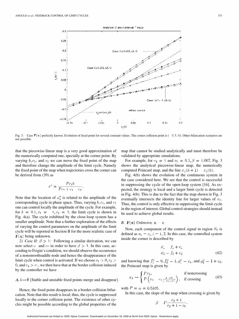
Fig. 3. Case F(x) perfectly known. Evolution of fixed point for several constant values. The corner collision point is (�0:1; 0). Other bifurcation scenarios arenot possible.
that the piecewise-linear map is a very good approximation ofthe numerically computed one, specially at the corner point. Byvarying , and we can move the fixed point of the mapand therefore change the amplitude of the limit cycle. Namelythe fixed point of the map when trajectories cross the corner canbe derived from (39) as
Note that the location of is related to the amplitude of thecorresponding cycle in phase space. Thus, varying , andone can control locally the amplitude of the cycle. For example,for , the limit cycle is shown inFig. 4(a). The cycle exhibited by the close-loop system has asmaller amplitude. Note that a further exploration of the effectsof varying the control parameters on the amplitude of the limitcycle will be reported in Section B for the more realistic case of
being unknown.2) Case II: : Following a similar derivation, we can
now select and in order to have . In this case, ac-cording to Feigin’s condition, we should observe the occurrenceof a nonsmoothsaddle node and hence the disappearance of thelimit cycle when control is activated. If we choose
, and , we then have that at the border collision inducedby the controller we have
Stable and unstable fixed points merge and disappear
Hence, the fixed point disappears in a border-collision bifur-cation. Note that this result is local; thus, the cycle is suppressedlocally to the corner collision point. The existence of other cy-cles might be possible according to the global properties of the
map that cannot be studied analytically and must therefore bevalidated by appropriate simulations.
For example, for and , Fig. 3shows the analytical piecewise-linear map, the numericallycomputed Poincaré map, and the line .
Fig. 4(b) shows the evolution of the continuous system inthe case considered here. We see that the control is successfulin suppressing the cycle of the open-loop system [16]. As ex-pected, the strategy is local and a larger limit cycle is detectedin Fig. 4(b). This is due to the fact that the map shown in Fig. 3eventually intersects the identity line for larger values of .Thus, the control is only effective in suppressing the limit cyclein the region of interest. Global control strategies should insteadbe used to achieve global results.
B. Unknown,
Now, each component of the control signal in region isdefined as . In this case, the controlled systeminside the corner is described by
(42)
and knowing that , and ,the Poincaré map is given by
if noncrossing
if crossing (43)
with .In this case, the slope of the map when crossing is given by
Authorized licensed use limited to: IEEE Xplore Customer. Downloaded on December 18, 2008 at 06:04 from IEEE Xplore. Restrictions apply.

374 IEEE TRANSACTIONS ON CIRCUITS AND SYSTEMS—I: REGULAR PAPERS, VOL. 52, NO. 2, FEBRUARY 2005
Fig. 4. Evolution of the system controlled withu = �F(x)+cwith differentcontrol parameters. Subfigures (a) and (b) are in the same scale. Subfigure (c)shows the behavior of the maximum effort control in case (b). (a) c = �1 andc = 1. (b) c = 0:5 and c = 1. (c) Control signal.
Fig. 5. Evolution of the system controlled with u = c Subfigures (a) and(b) are in the same scale. Subfigure (c) shows the behavior of the maximumeffort control in case (b). (a) c = �2 and c = 1, (b) c = 2 and c = 3,(c) Control signal.
Authorized licensed use limited to: IEEE Xplore Customer. Downloaded on December 18, 2008 at 06:04 from IEEE Xplore. Restrictions apply.
ANGULO et al.: FEEDBACK CONTROL OF LIMIT CYCLES 375
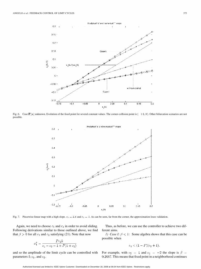
Fig. 6. Case F(x) unknown. Evolution of the fixed point for several constant values. The corner-collision point is (�0:1; 0). Other bifurcation scenarios are notpossible.
Fig. 7. Piecewise-linear map with a high slope. c = 2:8 and c = 3. As can be seen, far from the corner, the approximation loses validation.
Again, we need to choose and in order to avoid sliding.Following derivations similar to those outlined above, we findthat for all and satisfying (21). Note that now
and so the amplitude of the limit cycle can be controlled withparameters , and .
Thus, as before, we can use the controller to achieve two dif-ferent aims.
1) Case I: : Some algebra shows that this case can bepossible when
For example, with and the slope is. This means that fixed point in a neighborhood continues
Authorized licensed use limited to: IEEE Xplore Customer. Downloaded on December 18, 2008 at 06:04 from IEEE Xplore. Restrictions apply.

376 IEEE TRANSACTIONS ON CIRCUITS AND SYSTEMS—I: REGULAR PAPERS, VOL. 52, NO. 2, FEBRUARY 2005
Fig. 8. Relation between amplitude of the limit cycle and rms value when the desired oscillation has an amplitude lower than the original. The solid line correspondsto numerically computed values, while the points are computed with the analytical formula deduced in Section IV.
existing after the bifurcation. Fig. 5(a) shows the behavior of thecontinuous-time system with and without control. We see thatthe limit cycle persists as expected with a minor change of itsamplitude. This can be emphasised by selecting different valuesof and and hence moving further the fixed point of the map.
2) Case II: : Now we have
and the limit cycle disappears locally in a border collision bi-furcation. This case is possible too. It can be easily checked thatthe conditions on and are given by
For example, with and the slope is .Fig. 5(b) shows the behavior of the continuous-time system.We observe that the target cycle has disappeared locally aftera border collision bifurcation; the evolution of the map movingtoward another fixed point outside the range where the local de-scription is valid. Such a fixed point corresponds to the large-amplitude limit cycle depicted in the figure. Fig. 6 shows the an-alytical and numerical maps for Cases I and II confirming the ex-cellent agreement between the analysis and the numerics. (Notethat, for the sake of brevity, to obtain an analytical approxima-tion of the Poincaré map, we have truncated the discontinuitymap to its linear terms.).
It is worth to note that in all the cases, if the slope of thepiecewise-linear map is very high, the map based on the linearapproximation becomes representative of the system behaviorin a relatively small neighborhood of the bifurcation point (seeFig. 7).
3) Control Effort: In this subsection, the analytical formulasderived to estimate the control effort, when is unknown,are compared with the numerical values obtained. Constantsand are varied to obtain different lower or bigger amplitude
TABLE IAMPLITUDES OF LIMIT CYCLES AND RMS VALUES
limit cycles. Once the constants have been fixed, the corner pen-etration is varied to obtain different amplitudes. There is no uni-fied measure of an amplitude of a limit cycle. The original limitcycle is a circle and a natural measure can be its radius. Since theobtained limit cycles (after the control is applied) are approxi-mately circles also, which are centered at point , we take
(being the first coordinate when the limit cycle enters) as a measure of the amplitude. We have also computed an-
other measure of the amplitude, given by
with equivalent results.Table I shows the numerically computed rms value for cycles
with amplitudes bigger than the amplitude of the original limitcycle (in this case and ). Also, Fig. 8 shows therelation between amplitude of the limit cycle and the numerical(solid line) and analytical (dots) rms value when the desiredoscillation has an amplitude lower than the original (in this case
and ).As can be seen from Fig. 8, the limit cycle can disappear (the
amplitude is decreased to zero). Thus, the method can also con-trol the appearance and disappearance of limit cycles, thoughthis fact is nonlocal and cannot be explained by the theory in
Authorized licensed use limited to: IEEE Xplore Customer. Downloaded on December 18, 2008 at 06:04 from IEEE Xplore. Restrictions apply.

ANGULO et al.: FEEDBACK CONTROL OF LIMIT CYCLES 377
Fig. 9. Different values for the corner penetration give different meaningfulamplitude reductions, even suppressing the limit cycle. (a) Corner penetrationis set to�0:6. A small reduction in the amplitude of the limit cycle is obtained.(b) Corner penetration is set to �0:99. A considerable reduction of theamplitude is observed. (c) Corner penetration is set to �1, and the limit cycleturns into an equilibrium point. Also, the control effort is reduced to zero at thestationary point.
this paper. Fig. 9 shows different limit cycles when the cornerpenetration is varied far from the nonsmooth bifurcation.
VI. CONCLUSION
In this paper, we have shown that it is possible to synthesizea switching control law to suppress or change the main featuresof a target limit cycle in planar smooth dynamical system. Otherauthors [5], [6] have studied the bifurcation control problemfrom a smooth feedback framework. Our approach is differentsince switching (and thus nonsmooth) control laws are pro-posed. In so doing, the theory of nonsmooth bifurcations wasexplicitly used in the design process. Namely, by appropriatelyselecting the control constants and the switching manifolds,it is possible, to change the properties of the Poincaré mapassociated to the cycle of interest. The resulting control actionis acting on the system in a relatively small neighborhood of thecorner-collision point and hence guarantees the achievement ofthe control goal with a minimal control expenditure. We wishto emphasize that rather than being a technique for the controlof bifurcations in nonlinear systems, the strategy presentedhere aims at exploiting the theory of nonsmooth bifurcationsfor control system design.
Ongoing research is aimed at further exploring the ideas pre-sented in this paper and establish formal links between the con-troller gains and the properties of -limit set of the closed-loopsystem. Also, the extra degrees of freedom corresponding to thecontrol law parameters and (chosen here by using the addi-tional constraint of avoiding sliding) can be further exploited toobtain, for example, a given slope of the map when crossing,or to have solutions satisfying certain performance criteria. Fu-ture work will investigate this further and will also be concernedwith the experimental validation of this control strategy.
ACKNOWLEDGMENT
The authors acknowledge the comments of the referees toimprove the quality of the paper.
REFERENCES
[1] P. Davison, M. Lowenberg, and M. di Bernardo, “Experimental mod-eling and analysis of limit cycles in a dynamics wind tunnel rig,” J. Air-craft, pp. 776–785, 2003.
[2] G. Verghese and S. Banerjee, Eds., Nonlinear Phenomena in PowerElectronics. New York: IEEE Press, 2001.
[3] G. Chen, D. J. Hill, and X. Yu, Eds., Bifurcation Control: Theory andApplications. New York: Springer-Verlag, 2003.
[4] E. Sontag, Mathematical Control Theory. New York: Springer-Verlag,1998.
[5] E. H. Abed and J.-H. Fu, “Local feedback stabilization and bifurcationcontrol, I. Hopf bifurcation,” Syst. Contr. Lett., vol. 7, pp. 11–17, 1986.
[6] D. Aeyels, “Stabilization of a class of nonlinear systems by a smoothfeedback control,” Syst. Contr. Lett., vol. 5, pp. 289–294, 1985.
[7] F. Mastroddi and L. Morino, “Limit-cycle taming by nonlinear controlwith applications to flutter,” Aero. J. Roy. Aero. Soc., pp. 389–396, Nov.1996.
[8] G. Chen and X. Yu, Bifurcation Control. New York: Springer-Verlag,2003.
[9] F. Angulo, M. di Bernardo, E. Fossas, and G. Olivar, “Controllinglimit cycles in planar dynamical systems: A nonsmooth bifurcationapproach,” in Proc. IEEE Symp. Circuits and Systems, Vancouver, BC,Canada, May 2004.
Authorized licensed use limited to: IEEE Xplore Customer. Downloaded on December 18, 2008 at 06:04 from IEEE Xplore. Restrictions apply.

378 IEEE TRANSACTIONS ON CIRCUITS AND SYSTEMS—I: REGULAR PAPERS, VOL. 52, NO. 2, FEBRUARY 2005
[10] M. A. Hassouneh and E. H. Abed, “Control of Border collision bifur-cations,” in New Trends in Nonlinear Dynamics and Control and TheirApplications. New York: Springer-Verlag, 2004, vol. 295.
[11] M. di Bernardo, F. Garofalo, L. Iannelli, and F. Vasca, “Bifurcations inpiecewise smooth feedback systems,” Int. J. Contr., vol. 75, no. 16/17,pp. 1243–1259, 2002.
[12] Z. T. Zhusubaliyev and E. Mosekilde, Bifurcations and Chaos inPiecewise-Smooth Dynamical Systems. Singapore: World Scientific,2003.
[13] M. di Bernardo, C. J. Budd, and A. R. Champneys, “Corner collisionimplies border-collision bifurcation,” Phys. D., vol. 154, pp. 171–194,2001.
[14] M. di Bernardo, M. I. Feigin, S. J. Hogan, and M. E. Homer, “Localanalysis of c-bifurcations in n-dimensional piecewise-smooth dynam-ical systems,” Chaos, Solitons, Fractals, vol. 10, no. 11, pp. 1881–1908,1999.
[15] M. di Bernardo, C. J. Budd, and A. R. Champneys, “Corner collision im-plies border collision,” Phys. Rev. Lett., vol. 86, no. 12, pp. 2554–2556,2001.
[16] F. Angulo, M. di Bernardo, and G. Olivar, “Limit cycle control via non-smooth bifurcations,” in Proc. IEEE Conf. Decision Control, Atlantis,Bahamas, Dec. 2004.
Fabiola Angulo received the B.S. degree in elec-trical engineering with honors, the M.S. degree inautomatics, and the Ph.D. degree in automatics androbotics from Universidad Nacional de Colombia,Manizales, Colombia, Universidad Nacional deColombia, Bogota, Colombia, and UniversitatPolitécnica de Catalunya (UPC), Barcelona, Spain,in 1989, 2000, and 2004, respectively.
She is currently an Associate Professor in theDepartment of Electrical Engineering, Electronics,and Computer Science, Universidad Nacional de
Colombia, sede de Manizales. Her research interests include nonlinear con-trol, nonlinear dynamics of nonsmooth systems, and applications to dc–dcconverters. She is a member of the research group Perception and IntelligentControl (PCI), and head of many applied research projects.
Mario di Bernardo (S’95–M’01) was born inNaples, Italy, on May 11, 1970. He received thelaurea (M.Sc.) degree in control engineering and thePh.D. degree in applied mathematics and controlfrom the University of Naples “Federico II,” Naples,Italy, and the University of Bristol, Bristol, U.K., in1994 and 1998, respectively.
From 1997 to 2001, he was a Lecturer in NonlinearSystems in the Department of Engineering Mathe-matics, University of Bristol, where he is now a Vis-iting Professor. Since 2001, he was an Assistant Pro-
fessor in the Department of Engineering, University of Sannio, Benevento, Italy.Since January 2003, he is also an Associate Professor of Automatic Control atthe University of Naples “Federico II.” He is also a Visiting Professor at theUniversity of Bristol. Together with Bernard Brogliato (INRIA, France) he iscoordinating the EU Project SICONOS on the simulation and control of non-smooth dynamical systems. His research interests are within the broad area ofnonlinear systems, both dynamics and control. He is a regular columnist for UKNonlinear News and the newsletter of the IEEE Circuits and Systems Society.He is a reviewer for several international scientific journals.
Dr. di Bernardo served as an Associate Editor for the IEEE TRANSACTIONS ON
CIRCUITS AND SYSTEMS—I: FUNDAMENTAL THEORY AND APPLICATIONS from1999 to 2001, and is currently an Associate Editor of IEEE TRANSACTIONS ON
CIRCUITS AND SYSTEMS—II: EXPRESS BRIEFS. He was a member of the orga-nizing committees of the IEEE Symposia on Circuits and Systems 2000, 2001,and 2002 and was also involved with the organization of the successful ColstonSymposium on Nonlinear Dynamics, held in Bristol in June 2001. He is an as-sociate member of the International Centre for Chaos Control and Synchroniza-tion at the City University of Hong Kong and the Bristol Centre for AppliedNonlinear Mathematics and an active member of the Society for Industrial andApplied Mathematics.
Enric Fossas received the M.S. and Ph.D. degrees inmathematics from Barcelona University, Barcelona,Spain, in 1981 and 1986, respectively.
Since 1981, he has taught mathematics atBarcelona University and mathematics and au-tomatic control at the Universitat Politécnica deCatalunya, Barcelona, Spain, where he is currentlyan Assistant Professor in the Department of Au-tomatic Control and Computer Engineering andis also with the Institute of Industrial and ControlEngineering. His research interests include nonlinear
control (theory and applications), particularly variable structure systems, withapplications to switching converters.
Dr. Fossas is a member of the Society for Industrial and Applied Mathematics.
Gerard Olivar (M’99) received the M.S. degreein mathematics and the Ph.D. degree in mathe-matics from Barcelona University, Barcelona, Spainand Universitat Politécnica de Catalunya (UPC),Barcelona, Spain, in 1987 and 1997, respectively.
Since 1987, he is an Associate Professor inApplied Mathematics in the Technical Universityof Catalonia. He is a member of the research groupACES (Advanced Control of Energy Systems) andSARTI (Remote Acquisition and Data ProcessingSystems). He is author/co-author of more than 50
papers in international journals and conferences. He is a reviewer for several in-ternational scientific journals and head of several research projects. His researchinterests include nonlinear dynamics and bifurcations of piecewise-linear andpiecewise-smooth systems, with applications to dc–dc converters. He is amember of SEMA, and SCM Societies.
Authorized licensed use limited to: IEEE Xplore Customer. Downloaded on December 18, 2008 at 06:04 from IEEE Xplore. Restrictions apply.
Related Documents