ISO 9001:2008 CERTIFIED FEATURING: • Flow, Needle & Check Valves in Brass, Steel & Stainless • Flow, Needle & Check Valves in Brass, Aluminum, Steel & Stainless • BSP and SAE port threads available on selected valves • Pressure Compensated Flow Controls • Quick Exhaust Valves

Welcome message from author
This document is posted to help you gain knowledge. Please leave a comment to let me know what you think about it! Share it to your friends and learn new things together.
Transcript
ISO 9001:2008CERTIFIED
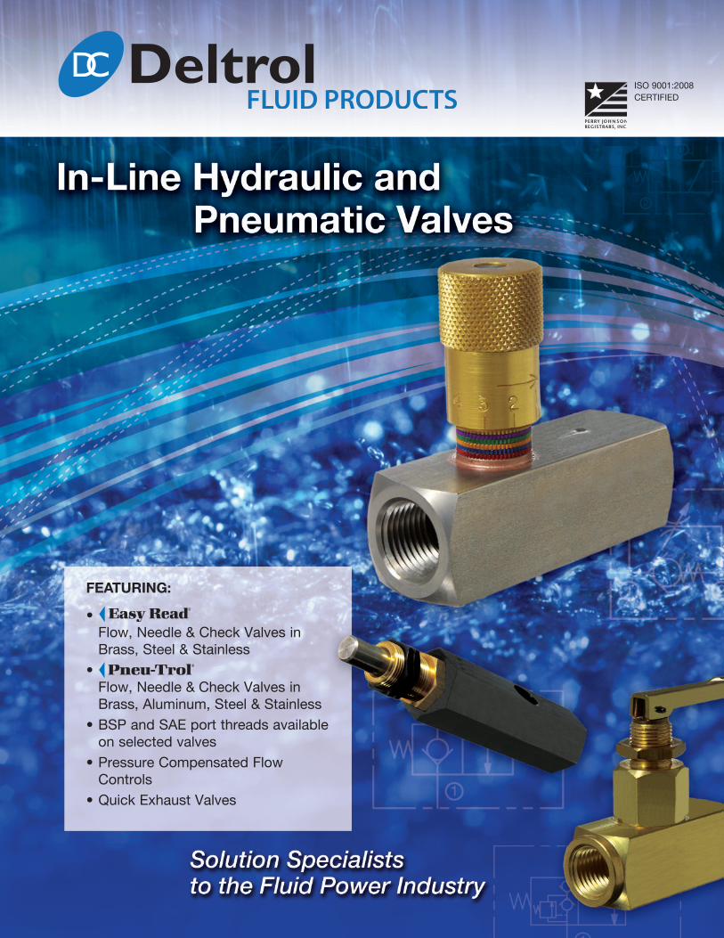
FEATURING:• Flow, Needle & Check Valves inBrass, Steel & Stainless
• Flow, Needle & Check Valves inBrass, Aluminum, Steel & Stainless
• BSP and SAE port threads availableon selected valves
• Pressure Compensated FlowControls
• Quick Exhaust Valves

I N- LI NE
Committed to TOTAL Customer Satisfaction
0.01.1
Deltrol Fluid Products strives for World Class Performance standards in product design, quality, competitive prices and quick response. Whether manufacturing an extensive range of fluid powerand fluid control components, or assisting in the design and building of the complete package,our goal remains...
TOTAL Customer SatisfactionAt Deltrol Fluid Products, our mission is to create and maintain an image of leader ship, quality and integrity with our customers, employees and suppliers. We continually strive to be a world-class manufacturer of cartridge valves, custom manifold systems, and in-line valves.
World ClassPerformance
HistoryLocated in Bellwood, Illinois, just outside of Chicago, andfounded in 1963, Deltrol Fluid Products designed and manufactured in-line accessory hydraulic and pneumatic flow, needle, and check valves. When screw-in style cartridge valve technology developed, our product offeringexpanded to include cartridge valves.Now, fifty years since our founding, we have expanded our
product line to include a full line of solenoid and manual operated, directional control, flow control, and pressure control screw-in and slip-in style cartridge valves.We offer a comprehensive line of standard products and
thrive on providing custom valves and integrated circuits thatmeet our customers’ needs.
DesignOur design group is divided into two cross-functional teams,which allows us to focus on product designs that meet ourcustomers’ requirements. The valve design group can develop valves independently or integrate with our systemsdesign group based on customers’ special applications andneeds. Our three-dimensional modeling software enables usto create the most compact and efficient solutions for our customers.
Integrated Manufacturing Our vertically integrated manufacturing facility enables us toproduce high quality, cost effective parts on site. Our state-of-the-art assembly and test equipment ensure efficientthrough-put that meets our demanding quality standards.
QualityOur ISO 9001-2008 certified and Six Sigma based qualitysystem ensures that our designs are produced to ourcustomers’ expectations. Our robust design verification andvendor qualification systems ensure smooth transition fromconcept to production. 100% of the products we produceare functionally tested with automated computer-driventest systems.
DeliveryOur MRP based manufacturing system gives us the flexibilityto meet our customers’ delivery system requirements. We are experienced in working with various customer implementations of pull order systems. We work closely tounderstand our customers’ ERP systems and have the flexibility to integrate our packaging and delivery with theirrequirements.
We take pride in our ability to provide high quality, cost effective customer solutions. We offer a wide range of standard products and excel at the opportunity to modify our current designs or develop unique products that meet our customers’ special needs.
If the solution you need is not available in our catalog or you have a special application, please contact us so wecan develop a component or system that meets your specific demands. Whether it’s a unique environment, flowmedia, fit, or application, we are eager to work with you to provide products and services that make you most competitive in your marketplace.
02/14
I N- LI NE
Series Threads (ports) Flow Pressure Material Model Pagegpm lpm psi bar
Female-to-FemaleNPTF
3.0 to 55.0 11.4 to 208.2 2000 138 BrassEC**B
1.01.1
EDC**B
6.0 to 55.0 22.7 to 208.2 5000 345CarbonSteel
EC**SEDC**S
6.0 to 20.0 22.7 to 75.7 5000 345 Stainless SteelEC**SSEDC**SS
Female-to-FemaleBSP Taper
3.0 to 20.0 11.4 to 75.7 5000 345CarbonSteel
ECB**S 1.01.1
Female-to-FemaleBSP Parallel
6.0 to 20.0 22.8 to 75.7 5000 345CarbonSteel
ECBP**S 1.01.1
Female-to-FemaleNPTF
1.5 to 12.0 5.7 to 45.460 4 Brass CP**B
1.02.12000 138 Brass C**B5000 345 Carbon Steel C**S
1.5 to 8.0 5.7 to 30.3 5000 345 Stainless Steel C**SS1.5 to 3.0 5.7 to 11.4 60 4 Stainless Steel CP**SS
Male-to-FemaleNPTF 1/4" 2.5 9.5 60 4 Brass CPMF20B 1.03.1
Male-to-MaleNPTF
1.0 to 10.0 3.8 to 37.9 2000 138 Brass CMM**B1.04.12.5 to 10.0 9.5 to 37.9
3000 207Carbon Steel CMM**S
2.5 9.5 Stainless Steel CMM20SS2
Male-to-MaleNPTF (Soft Seat)
1.0 to 15.0 3.8 to 56.8 2000 138 Brass CMM***B1.04.12.5 to 10.0 9.5 to 37.9
3000 207Carbon Steel CMM***S
2.5 to 6.0 9.5 to 22.8 Stainless Steel CMM***SS
Table of Contents
0.02.102/14
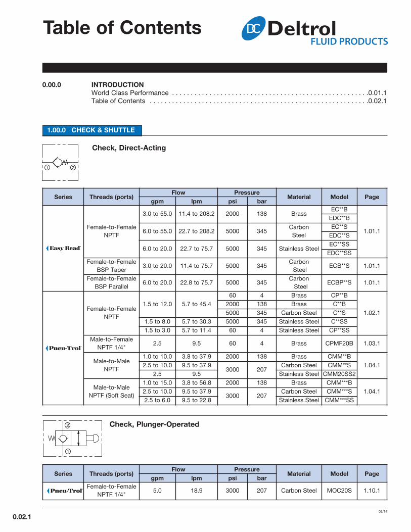
1.00.0 CHeCk & SHuTTLe
Check, Direct-Acting
Check, Plunger-Operated
Series Threads (ports) Flow Pressure Material Model Pagegpm lpm psi barFemale-to-Female
NPTF 1/4" 5.0 18.9 3000 207 Carbon Steel MOC20S 1.10.1
0.00.0 InTrODuCTIOnWorld Class Performance . . . . . . . . . . . . . . . . . . . . . . . . . . . . . . . . . . . . . . . . . . . . . . . . . . . . .0.01.1Table of Contents . . . . . . . . . . . . . . . . . . . . . . . . . . . . . . . . . . . . . . . . . . . . . . . . . . . . . . . . . . .0.02.1
I N- LI NE
(continued)
07/13
0.02.2
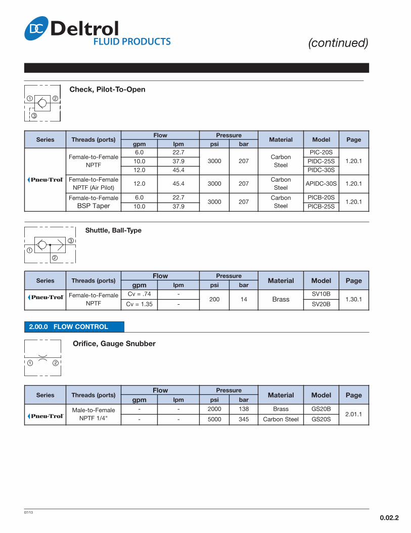
Check, Pilot-To-Open
Series Threads (ports) Flow Pressure Material Model Pagegpm lpm psi bar
Female-to-FemaleNPTF
6.0 22.73000 207
CarbonSteel
PIC-20S1.20.110.0 37.9 PIDC-25S
12.0 45.4 PIDC-30S
Female-to-FemaleNPTF (Air Pilot)
12.0 45.4 3000 207CarbonSteel
APIDC-30S 1.20.1
Female-to-FemaleBSP Taper
6.0 22.73000 207
CarbonSteel
PICB-20S1.20.1
10.0 37.9 PICB-25S
Shuttle, Ball-Type
Series Threads (ports) Flow Pressure Material Model Pagegpm lpm psi barFemale-to-Female
NPTF
Cv = .74 -200 14 Brass
SV10B1.30.1
Cv = 1.35 - SV20B
2.00.0 FLOW COnTrOL
Orifice, Gauge Snubber
Series Threads (ports) Flow Pressure Material Model Pagegpm lpm psi barMale-to-FemaleNPTF 1/4"
- - 2000 138 Brass GS20B2.01.1
- - 5000 345 Carbon Steel GS20S

I N- LI NE
Table of Contents(continued)
0.02.302/14
needle Valve, restrictive, Adjustable
Series Threads (ports) Flow Pressure Material Model Pagegpm lpm psi bar
Female-to-FemaleNPTF
4.5 to 100.0 17.1 to 378.52000 138 Brass EN***B
2.10.15000 345 Carbon Steel EN***S10.0 37.9 5000 345 Stainless Steel EN20SS
Female-to-FemaleBSP Taper
4.5 to 40.0 17.1 to 151.42000 138 Brass ENB**B
2.10.15000 345 Carbon Steel ENB**S
Female-to-FemaleBSP Parallel
10.0 to 18.0 37.9 to 68.1 2000 138 Brass ENBP**B2.10.1
4.5 to 40.0 17.1 to 151.4 5000 345 Carbon Steel ENBP**S
Female-to-FemaleNPTF
3.2 to 34.0 12.1 to 128.7 2000 138 Brass N**B
2.11.13.2 to 34.0 12.1 to 128.7 5000 345 Carbon Steel N**S
3.2 to 22.5 12.1 to 85.2 5000 345 Stainless Steel N**SSK
Female-to-FemaleBSP Taper
3.2 to 13.5 12.1 to 51.1 2000 138 Brass NB**BK2.11.1
3.2 to 34.0 12.1 to 128.7 5000 345 Carbon Steel NB**SK
Female-to-FemaleSAE
7.0 to 34.0 26.5 to 128.7 5000 345 Carbon Steel NM***SK 2.11.1
Male-to-FemaleNPFT
Model 01
Cv = .67 to1.89
- 10,000 690 Carbon Steel S*01S1 2.15.1
Female-to-FemaleNPTF
Model 02
Cv = .85 to3.70
- 10,000 690 Carbon Steel S*02S12.15.1
Cv = .85 - 10,000 690 Carbon Steel SM202S1
Female-to-FemaleBSPT
Model 02
Cv = .85 to3.70
- 10,000 690 Carbon Steel SB*02S1 2.15.1
Female-to-FemaleNPTF
Model 50
Cv = .37 to4.65
- 10,000 690 Carbon Steel S*50S12.15.1
Cv = .37 to.47
- 10,000 690 Carbon Steel SM*50S1
Female-to-FemaleBSPT
Model 50
Cv = .47 to2.65
- 10,000 690 Carbon Steel SB*50S1 2.15.1
Female-to-FemaleBSPP
Model 50
Cv = .47 to2.65
- 10,000 690 Carbon Steel SBP*50S1 2.15.1
Male-to-FemaleNPTF
3.2 to 7.0 12.1 to 26.5 2000 138 Brass NMF**BK2.16.1
7.0 to 13.5 26.5 to 51.1 5000 345 Carbon Steel NMF**SK
Male-to-FemaleNPTF
3.2 12.1 5000 345 Steel NMF20-10S 2.17.1
Female-to-FemaleNPTF
3.2 12.1 5000 345 Steel N20-10S 2.18.1

Series Threads (ports)Flow Pressure
Material Model Pagegpm lpm psi bar
Female-to-FemaleNPTF
1.5 5.7 1000 69Stainless Steel
SFP10SSB2.21.1
3.0 11.5 500 34 SFP20SSB
Female-to-FemaleNPTF
1.5 to 5.0 5.7 to 18.9 60 4 Brass FP**B
2.22.11.5 to 12.0 5.7 to 45.4 2000 138 Brass F**B
1.5 to 12.0 5.7 to 45.4 5000 345 Carbon Steel F**S
1.5 to 8.0 5.7 to 30.3 5000 345 Stainless Steel F**SSK
Female-to-FemaleBSP Taper
1.5 to 5.0 5.7 to 18.9 2000 138 Brass FB**BK2.22.1
1.5 to 12.0 5.7 to 45.4 5000 345 Carbon Steel FB**SK
Female-to-FemaleSAE
5.0 18.9 5000 345 Carbon Steel FM620S 2.22.1
Male-to-FemaleNPFT
1.5 to 8.0 5.7 to 30.3 2000 138 Brass FMF**BK 2.23.1
Female-to-FemaleNPTF
3.0 11.45000 345 Stainless Steel
F20SS316K2.24.1
8.0 30.3 F30SS316K
Female-to-FemaleNPTF
3.0 to 55.0 11.4 to 208.22000 138 Brass EF**B
2.25.15000 345 Carbon Steel EF**S
3.0 to 12.0 11.4 to 45.4 5000 345 Stainless Steel EF**SS
Female-to-FemaleBSP Taper
3.0 to 20.0 11.4 to 75.72000 138 Brass EFB**B
2.25.15000 345 Carbon Steel EFB**S
Female-to-FemaleBSP Parallel
3.0 to 12.0 11.4 to 45.4 2000 138 Brass EFBP**B2.25.1
3.0 to 20.0 11.4 to 75.7 5000 345 Carbon Steel EFBP**S
Female-to-FemaleSAE
6.0 to 20.0 22.7 to 75.7 5000 345 Carbon Steel EFM****S 2.25.1
I N- LI NE
(continued)
02/14
0.02.4
Flow Control, Free reverse Flow, Adjustable
Flow regulator, restrictive, Pressure-Compensated, Fixed
Series Threads (ports) Flow Pressure Material Model Pagegpm lpm psi barFemale-to-Female
NPTF0.1 to 2.0 0.4 to 7.6
3000 207Steel PC3
2.30.10.5 to 30.0 1.9 to 113.6 Alum. / Steel PC4
Female-to-FemaleSAE
0.1 to 2.0 0.4 to 7.6
3000 207
Steel PCM63
2.30.1
0.5 to 5.0 1.9 to 18.9 Aluminum PCM44
1.0 to 10.0 3.8 to 37.9 Aluminum PCM64
1.5 to 15.0 5.7 to 56.8 Steel PCM84
2.0 to 30.0 7.6 to 113.6 Steel PCM124
I N- LI NE
Table of Contents(continued)
0.02.502/14
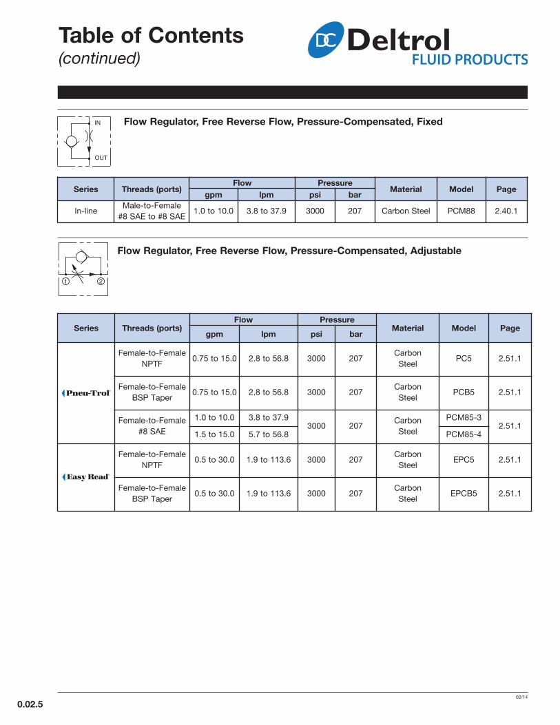
Flow regulator, Free reverse Flow, Pressure-Compensated, Fixed
Series Threads (ports) Flow Pressure Material Model Pagegpm lpm psi barIn-line
Male-to-Female#8 SAE to #8 SAE
1.0 to 10.0 3.8 to 37.9 3000 207 Carbon Steel PCM88 2.40.1
Flow regulator, Free reverse Flow, Pressure-Compensated, Adjustable
Series Threads (ports)Flow Pressure
Material Model Pagegpm lpm psi bar
Female-to-FemaleNPTF
0.75 to 15.0 2.8 to 56.8 3000 207CarbonSteel
PC5 2.51.1
Female-to-FemaleBSP Taper
0.75 to 15.0 2.8 to 56.8 3000 207CarbonSteel
PCB5 2.51.1
Female-to-Female#8 SAE
1.0 to 10.0 3.8 to 37.93000 207
CarbonSteel
PCM85-32.51.1
1.5 to 15.0 5.7 to 56.8 PCM85-4
Female-to-FemaleNPTF
0.5 to 30.0 1.9 to 113.6 3000 207CarbonSteel
EPC5 2.51.1
Female-to-FemaleBSP Taper
0.5 to 30.0 1.9 to 113.6 3000 207CarbonSteel
EPCB5 2.51.1

I N- LI NE
(continued)
02/14
0.02.6
3.00.0 DIreCTIOnAL VALVeS
Directional, Two-Way, Two-Position, normally-Closed, Plunger-Operated
Series Threads (ports) Flow Pressure Material Model Pagegpm lpm psi barFemale-to-Female
NPTF 1/2" Cv = 2.6 - 3000 207 Steel POV32S 3.01.1
Series Threads (ports) Flow Pressure Material Model Pagegpm lpm psi barFemale-to-Female
NPTF 1/4" 5.0 18.9 2000 138 Brass TV20B 3.02.1
Directional, Two-Way, Two-Position, normally-Closed, Toggle-Operated
4.00.0 ACCeSSOrIeS
Series Threads (ports) Flow Pressure Material Model Pagegpm lpm psi barFemale-to-Female
NPTFCv = .50 to
5.32- 20 to 125 1.0 to 9.0 Aluminum EV 4.10.1
Quick exhaust, 2-Position 3-Way
Slide Valve, 2-Position, 3-Way, Manually Operated
Series Threads (ports) Flow Pressure Material Model Pagegpm lpm psi barFemale-to-Female
NPTFCv = .98 to
3.26- 250 17 Steel / Brass SL 4.20.1

I N- LI NE
Table of Contents(continued)
0.02.707/13
Series Threads (ports) Flow Pressure Material Model Pagegpm lpm psi barFemale-to-Female
NPTF 1/4" - - 5000 345 Carbon Steel AB20S 4.30.1
Air Bleed Valve
6.00.0 MInIATure SerIeS
LFC, LFV and LNB Series Miniature Flow Control andNeedle Valves – MBV Series Miniature Ball Valves . . . . . . . . . . . . . . . . . . . . . . . . . . . . . . . . .6.00.0
Flow Control & needle Valve
LFC and LFV Series Miniature Flow Control . . . . . . . . . . . . . . . . . . . . . . . . . . . . . . . . . . . . . . .6.01.1LNB Series Miniature Needle Valve . . . . . . . . . . . . . . . . . . . . . . . . . . . . . . . . . . . . . . . . . . . . .6.01.1
Ball Valve
MBV Series Miniature Ball Valve . . . . . . . . . . . . . . . . . . . . . . . . . . . . . . . . . . . . . . . . . . . . . . . .6.02.1
5.00.0 TeCHnICAL DATA
Gauge Isolator
Series Threads (ports) Flow Pressure Material Model Pagegpm lpm psi barFemale-to-Female
NPTF 1/4" - - 3000 207 Steel GI21S 4.25.1
7.00.0 WArrAnTy AnD DISCLAIMer
FLOW CurVeSNeedle Valve: EN, ENB, ENM, ENBPFlow Control Valve : EF, EFB, EFM, EFBP . . . . . . . . . . . . . . . . . . . . . . . . . . . . . . . . . . . . . . . .5.01.1
. . . . . . . . . . . . . . . . . . . . . . . . . . . . . . . . . . . . . . . . . . . . . . . . .7.99.1

notes
eC, eDC Check ValveFemale-to-Female
3-5 02/14
IN-LINE
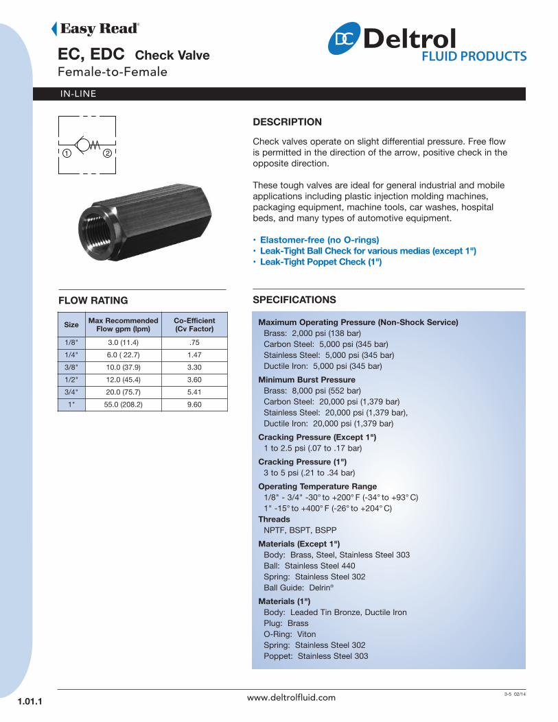
DeSCrIPTIOnCheck valves operate on slight differential pressure. Free flowis permitted in the direction of the arrow, positive check in theopposite direction.
These tough valves are ideal for general industrial and mobileapplications including plastic injection molding machines,packaging equipment, machine tools, car washes, hospitalbeds, and many types of automotive equipment.
• elastomer-free (no O-rings)• Leak-Tight Ball Check for various medias (except 1")• Leak-Tight Poppet Check (1")
SPeCIFICATIOnS
Maximum Operating Pressure (non-Shock Service)Brass: 2,000 psi (138 bar)Carbon Steel: 5,000 psi (345 bar)Stainless Steel: 5,000 psi (345 bar)Ductile Iron: 5,000 psi (345 bar)
Minimum Burst PressureBrass: 8,000 psi (552 bar)Carbon Steel: 20,000 psi (1,379 bar)Stainless Steel: 20,000 psi (1,379 bar),Ductile Iron: 20,000 psi (1,379 bar)
Cracking Pressure (except 1")1 to 2.5 psi (.07 to .17 bar)
Cracking Pressure (1")3 to 5 psi (.21 to .34 bar)
Operating Temperature range1/8" - 3/4" -30° to +200° F (-34° to +93° C)1" -15° to +400° F (-26° to +204° C)
ThreadsNPTF, BSPT, BSPP
Materials (except 1")Body: Brass, Steel, Stainless Steel 303Ball: Stainless Steel 440Spring: Stainless Steel 302Ball Guide: Delrin®
Materials (1")Body: Leaded Tin Bronze, Ductile IronPlug: BrassO-Ring: VitonSpring: Stainless Steel 302Poppet: Stainless Steel 303
Size Max recommendedFlow gpm (lpm)
Co-efficient (Cv Factor)
1/8" 3.0 (11.4) .75
1/4" 6.0 ( 22.7) 1.47
3/8" 10.0 (37.9) 3.30
1/2" 12.0 (45.4) 3.60
3/4" 20.0 (75.7) 5.41
1" 55.0 (208.2) 9.60
FLOW rATInG
1.01.1 www.deltrolfluid.com

IN-LINE
1.01.2
(continued)eC, eDC Check Valve
Female-to-Female
InSTALLATIOn DIMenSIOnS
e*
Code Check ValveeC
Check ValveeDC
Code ThreadOmit NPTF
B BSPT
BP BSPP
Code Size10 1/8"
20 1/4"
25 3/8"
30 1/2"
35 3/4"
40 1"
Code Material
B Brass (1"- Leaded Tin Bronze)
S Carbon Steel (1"- Ductile Iron)
SS Stainless Steel
AVAILABLe MODeL CODeS
HOW TO OrDer
Size
nPTF Thread ISO 7/1 - rSBSP Taper
ISO 7/1 - rPBSP Parallel
Brass Steel StainlessSteel Steel Steel
1/8" EC10B – – ECB10S –
1/4" EC20B EC20S EC20SS ECB20S ECBP20S
3/8" EDC25B EDC25S EDC25SS ECB25S ECBP25S
1/2" EDC30B EDC30S EDC30SS ECB30S ECBP30S
3/4" EDC35B EDC35S EDC35SS ECB35S ECBP35S
1" EC40B EC40S – – –
Pipe Size A HeX B C D orifice
1/8" 5/8 (15.9)
1-11/16 (42.9) – .188
(4.8)
1/4" 3/4 (19.1)
2 (50.8) – .250
(6.4)
3/8" 1 (25.4)
2-1/2 (63.5) – .328
(8.3)
1/2" 1-1/8 (28.6)
2-7/8 (73.1) – .359
(9.1)
3/4" 1-3/8 (35.0)
3-1/4 (82.6) – .526
(13.4)
1" 1-3/4 (44.5)
4-1/2 (114.3)
2-13/32 (61.2)
.875 (22.2)
CheckValve Thread Size Material
A
CHECK VALVECHECK VALVE
1 2
www.deltrolfluid.com
1 2
( ) Parentheses = Millimeters
IN-LINE
C, CP Check ValveFemale-to-Female
8-9 02/14
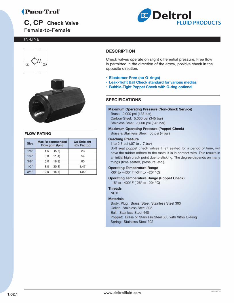
DeSCrIPTIOnCheck valves operate on slight differential pressure. Free flowis permitted in the direction of the arrow, positive check in theopposite direction.
• elastomer-Free (no O-rings)• Leak-Tight Ball Check standard for various medias• Bubble-Tight Poppet Check with O-ring optional
SPeCIFICATIOnS
Maximum Operating Pressure (non-Shock Service)Brass: 2,000 psi (138 bar)Carbon Steel: 5,000 psi (345 bar)Stainless Steel: 5,000 psi (345 bar)
Maximum Operating Pressure (Poppet Check)Brass & Stainless Steel: 60 psi (4 bar)
Cracking Pressure1 to 2.5 psi (.07 to .17 bar)Soft seat poppet check valves if left seated for a period of time, willhave the rubber adhere to the metal it is in contact with. This results inan initial high crack point due to sticking. The degree depends on manythings (time seated, pressure, etc.).
Operating Temperature range-30° to +400° F (-34° to +204° C)
Operating Temperature range (Poppet Check)-15° to +400° F (-26° to +204° C)
ThreadsNPTF
MaterialsBody, Plug: Brass, Steel, Stainless Steel 303Collar: Stainless Steel 303Ball: Stainless Steel 440Poppet: Brass or Stainless Steel 303 with Viton O-RingSpring: Stainless Steel 302
FLOW rATInG
Size Max recommendedFlow gpm (lpm)
Co-efficient (Cv Factor)
1/8" 1.5 (5.7) .23
1/4" 3.0 (11.4) .54
3/8" 5.0 (18.9) .83
1/2" 8.0 (30.3) 1.47
3/4" 12.0 (45.4) 1.90
1.02 .1 www.deltrolfluid.com

IN-LINE
Code Check ValveC Ball Check
CP Poppet Check
Code ThreadOmit NPTF
Code Size10 1/8"
20 1/4"
25 3/8"
30 1/2"
35 3/4"
Code MaterialB Brass
S Carbon Steel
SS Stainless Steel
A
Pipe Size A HeX B C D orifice
1/8" 11/16 (17.5)
1-15/32 (37.3)
13/64 (5.2)
.141 (3.6)
1/4" 7/8 (22.2)
2(50.8)
23/64(9.1)
.203 (5.2)
3/8" 1-1/16(27.0)
2-1/4(57.2)
11/32(8.7)
.266 (6.8)
1/2" 1-5/16(33.4)
2-21/32(67.5)
15/32 (11.9)
.328 (8.3)
3/4” 1-5/8(41.3)
2-15/16(74.6)
17/32 (13.5)
.406 (10.3)
( ) Parentheses = Millimeters
AVAILABLe MODeL CODeS
HOW TO OrDer
SizenPTF Thread
Brass Steel Stainless Steel
1/8"C10B
C10SC10SS
CP10B CP10SS
1/4"C20B
C20SC20SS
CP20B CP20SS
3/8"C25B
C25S C25SSCP25B
1/2" CP30B C30S C30SS
3/4" C35B C35S –
1.02.2
C*CheckValve Thread Size Material
(continued)C, CP Check Valve
Female-to-Female
21
InSTALLATIOn DIMenSIOnS
www.deltrolfluid.com
1 2
CPCheckValve Thread Size Material
MF 20 B
IN-LINE
CPMF20B Check ValveMale-to-Female
10 02/14
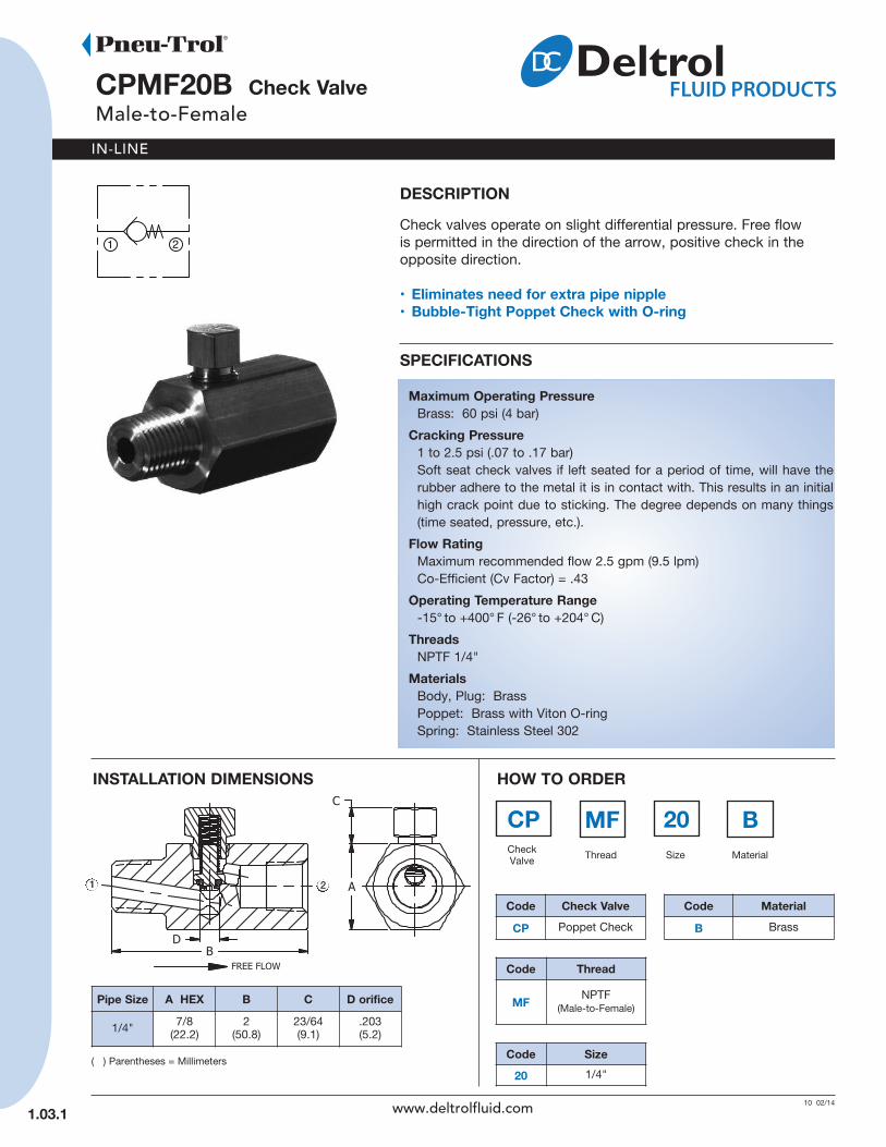
DeSCrIPTIOnCheck valves operate on slight differential pressure. Free flowis permitted in the direction of the arrow, positive check in theopposite direction.
• eliminates need for extra pipe nipple• Bubble-Tight Poppet Check with O-ring
SPeCIFICATIOnS
Maximum Operating PressureBrass: 60 psi (4 bar)
Cracking Pressure1 to 2.5 psi (.07 to .17 bar)Soft seat check valves if left seated for a period of time, will have the rubber adhere to the metal it is in contact with. This results in an initial high crack point due to sticking. The degree depends on many things (time seated, pressure, etc.).
Flow ratingMaximum recommended flow 2.5 gpm (9.5 lpm)Co-Efficient (Cv Factor) = .43
Operating Temperature range-15° to +400° F (-26° to +204° C)
ThreadsNPTF 1/4"
MaterialsBody, Plug: BrassPoppet: Brass with Viton O-ringSpring: Stainless Steel 302
Pipe Size A HeX B C D orifice
1/4" 7/8(22.2)
2(50.8)
23/64(9.1)
.203(5.2)
( ) Parentheses = Millimeters
HOW TO OrDer
Code Check ValveCP Poppet Check
Code Thread
MF NPTF(Male-to-Female)
Code Size20 1/4"
Code MaterialB Brass
InSTALLATIOn DIMenSIOnS
1.03.1
21
www.deltrolfluid.com

IN-LINE
CMM Check ValveMale-to-Male
11 02/14
1.04.1
InSTALLATIOn DIMenSIOnS
( ) Parentheses = Millimeters
HOW TO OrDer
DeSCrIPTIOnCheck valves operate on slight differential pressure. Free flowis permitted in the direction of the arrow, positive check in the opposite direction.
• elastomer-free (no O-ring) Leak-Tight Ball Checkstandard for various medias
• Bubble-Tight Ball Check with O-ring/Quad ring optional• Compact over-all length
SPeCIFICATIOnS
Maximum Operating PressureBrass: 2,000 psi (138 bar)Carbon Steel: 3,000 psi (207 bar)Stainless Steel: 3,000 psi (207 bar)
Cracking Pressure1 to 2.5 psi (.07 to .17 bar)Other cracking pressures available.Consult factory.Soft seat check valves if left seated fora period of time, will have the rubber adhereto the metal it is in contact with. This resultsin an initial high crack point due to sticking.The degree depends on many things(time seated, pressure, etc.).
PipeSize A HeX B C orifice gpm
(lpm)Cv
Factor1/8" 7/16
(11.1)31/32 (24.6)
.125(3.2)
1.0(3.8) .17
1/4" 5/8 (15.9)
1-3/8(34.9)
.188(4.8)
2.5(9.5) .56
3/8" 3/4(19.1)
1-5/8(41.3)
.250(6.4)
6.0(22.7) 1.31
1/2" 7/8(22.2)
2-1/16(52.4)
.328(8.3)
10.0(37.9) 2.71
3/4” 1-1/8(28.6)
2-1/4(57.2)
.359(9.1)
15.0(56.8) 3.40
Leak-Tight
SizenPTF Thread
Brass Steel StainlessSteel
1/8" CMM10B1 — —1/4" CMM20B CMM20S CMM2OSS23/8" CMM25B CMM25S —1/2" CMM30B CMM30S —
Bubble-Tight(O = O-ring, Q = Quad ring)
SizenPTF Thread
Brass Steel StainlessSteel
1/8" CMMO10B1 — —
1/4" CMMQ20B CMMQ20S CMMO20SS2
3/8" CMMO25B CMMO25S CMMO25SS
1/2" CMMQ30B CMMQ30S —
3/4" CMMQ35B — —
1
www.deltrolfluid.com
Operating Temperature range-30° to +200° F (-34° to +93° C)
ThreadsNPTF
MaterialsBody: Brass, Steel, Stainless Steel 303Ball: Stainless Steel 440Spring: Stainless Steel 302Ball Guide: Delrin®
Washer: Stainless Steel 304O-Ring/Quad Ring: Buna-N
1 2
2

IN-LINE
11 01/14
DeSCrIPTIOnPlunger-Operated Check Valve. Check valves operate on slightdifferential pressure. Free flow is permitted in the direction of thearrow, positive check in the opposite direction. Reverse flow canbe achieved by manually depressing plunger.
• normally-Closed, Push-to-Open• For hydraulic or pneumatic applications• Pneumatic applications are not Bubble-Tight
SPeCIFICATIOnS
Maximum Operating Pressure(non-Shock Service)Carbon Steel: 3,000 psi (207 bar)
Cracking Pressure1 to 2.5 psi (.07 to .17 bar)
Maximum recommended Flow5.0 gpm (18.9 lpm)Co-Efficient (Cv Factor) = .54
Operating Temperature range-30° to +200° F (-34° to +93° C)
Plunger effort70 lbs. (311 N) per 1,000 psi (69 bar)
ThreadsNPTF 1/4"
HOW TO OrDer
SizenPTF Thread
Steel1/4" MOC20S
InSTALLATIOn DIMenSIOnS
( ) Parentheses = Millimeters
1.10.1
MOC20S Check, Plunger-OperatedFemale-to-Female
www.deltrolfluid.com
MaterialsBody: SteelHousing: BrassNuts: SteelPlunger: Stainless Steel 303Piston: SteelSprings: Music wireO-Ring: Buna-NBack-Up Washer: TeflonBall: Stainless Steel 440Ball Guide: Delrin®
Washer: Dtainless Steel 304Retainer Ring: Steel
1
2

IN-LINE
Check, Pilot-to-OpenFemale-to-Female
19 02/14
InSTALLATIOn DIMenSIOnS
( ) Parentheses = Millimeters
HOW TO OrDer
DeSCrIPTIOnPilot-Operated Check Valve. Check valves operate on slightdifferential pressure. Free flow is permitted in the direction of the arrow, positivecheck in the opposite direction. Reverse flow can be achieved by reaching therequired pilot pressure at port (3).
• For hydraulic applications only• Air pilot valves have secondary seal on pilot piston stem.
A vent hole in the body between the piston seal and stem seal prevents mixing of pilot media and the system media
SPeCIFICATIOnS
Maximum Operating PressureCarbon Steel: 3,000 psi (207 bar)
Operating Temperature rangeBuna-N: -30° to +200° F (-34° to +93° C)
Maximum recommended Flow6.0 to 12.0 gpm (22.7 to 45.4 lpm)
Pilot ratio4:1 Hydraulic Pilot2:1 Hydraulic Pilot under 90 psi (6 bar)2:1 Air Pilot
ThreadsNPTF, BSPT
PipeSize A HeX B C D orifice Pilot
PortInletPort
OutletPort
1/4" 1-1/8(28.6)
4-1/8 (104.8)
1-27/32(43.7)
.281(7.1) 1/4" 1/4" 1/4"
3/8" 1-3/8(34.9)
4-7/8(123.8)
2-1/8(54.0)
.328(8.3) 1/4" 3/8" 3/8"
1/2" 1-5/8(41.3)
5-5/8(142.9)
2-7/16(61.9)
.359(9.1) 1/4" 1/2" 1/2"
nPTF Thread
Size AirPilot
HydraulicPilot
Max. Flowgpm (lpm)
1/4" — PIC20S 6.0 (22.7)
3/8" — PIDC25S 10.0 (37.9)
1/2" APIDC30S PIDC30S 12.0 (45.4)
ISO 7/1 – rS BSP Taper Thread
Size HydraulicPilot
Max. Flow gpm (lpm)
1/4" PICB20S 6.0 (22.7)
3/8" PICB25S 10.0 (37.9)
1.20.1
1
23
www.deltrolfluid.com
MaterialsBody: SteelAdapter: SteelO-Rings: Buna-N (PIC, PIDC)
Viton (APIDC)Piston: SteelPiston Spring: Music wireCheck Spring: Stainless Steel 302Piston Seals: Teflon (PIC, PIDC)
Viton (APIDC)Teflon Back-up Washer (APIDC)
Ball: Stainless Steel 440Ball Guide: Delrin®
Washer: Stainless Steel 304Retainer Ring: Steel
1
23

IN-LINE
SV Shuttle, Ball-TypeFemale-to-Female
19 01/14
DeSCrIPTIOnOperates as a three-way valve with two inlet ports and oneoutlet port. The check ball moves away from the inlet port withthe greatest differential pressure and against the port having theleast differential pressure.
• Bubble-Tight Ball Check with O-rings
SPeCIFICATIOnS
Maximum Operating Pressure (non-Shock Service)Brass: 200 psi (14 bar)
Flow ratingCo-Efficient (Cv Factor) = .74 and 1.35
Operating Temperature range-30° to +250° F (-34° to +120° C)
ThreadsNPTF
MaterialsBody, Adapters, Retainers: BrassBall: Stainless Steel 440O-Rings: Buna-N
HOW TO OrDer
SizenPTF Thread Co-efficient
(Cv Factor)Brass1/8" SV10B .74
1/4" SV20B 1.35
InSTALLATIOn DIMenSIOnS
( ) Parentheses = Millimeters
PipeSize A B C D orifice
1/8" 1-1/4(31.8)
31/32 (24.6)
5/8(15.9)
.188(4.8)
1/4" 1-7/8(47.6)
1-5/16(33.4)
7/8(22.2)
.250(6.4)
1.30.1
1
2
3
www.deltrolfluid.com
IN-LINE
GS20 Gauge SnubberMale-to-Female
13 02/14
InSTALLATIOn DIMenSIOnS
( ) Parentheses = Millimeters
HOW TO OrDer
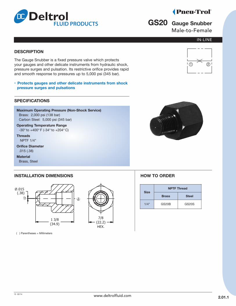
DeSCrIPTIOnThe Gauge Snubber is a fixed pressure valve which protectsyour gauges and other delicate instruments from hydraulic shock,pressure surges and pulsation. Its restrictive orifice provides rapidand smooth response to pressures up to 5,000 psi (345 bar).
• Protects gauges and other delicate instruments from shock pressure surges and pulsations
SPeCIFICATIOnS
Maximum Operating Pressure (non-Shock Service)Brass: 2,000 psi (138 bar)Carbon Steel: 5,000 psi (345 bar)
Operating Temperature range-30° to +400° F (-34° to +204° C)
ThreadsNPTF 1/4"
Orifice Diameter.015 (.38)
MaterialBrass, Steel
SizenPTF Thread
Brass Steel
1/4" GS20B GS20S
2.01.1
1 2
www.deltrolfluid.com
IN-LINE
3-5 02/14
2.10.1
en needle ValveFemale-to-Female
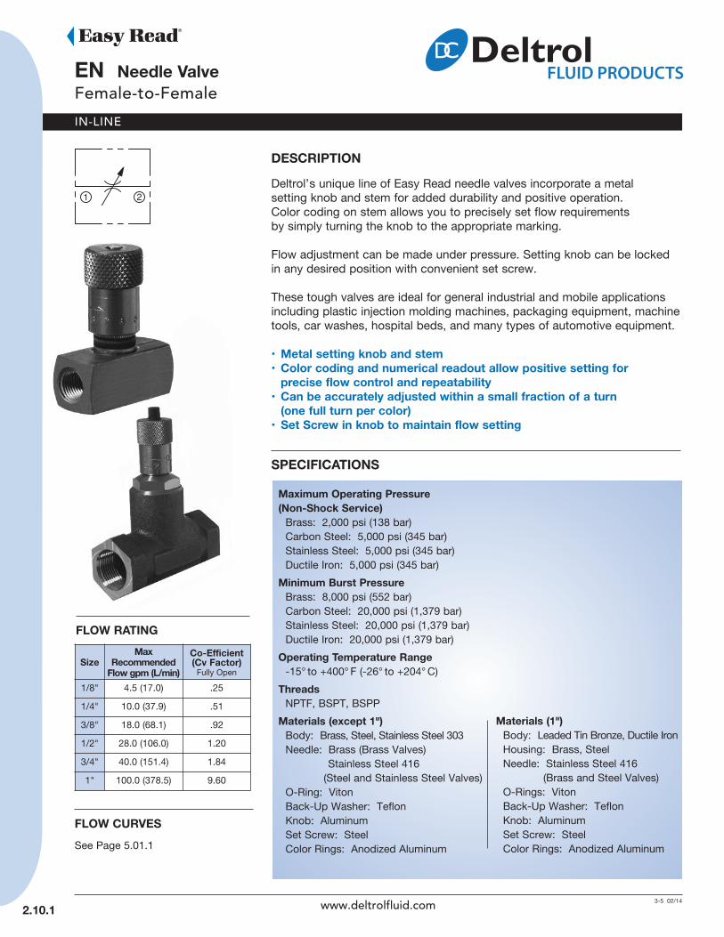
DeSCrIPTIOnDeltrol’s unique line of Easy Read needle valves incorporate a metalsetting knob and stem for added durability and positive operation.Color coding on stem allows you to precisely set flow requirementsby simply turning the knob to the appropriate marking.
Flow adjustment can be made under pressure. Setting knob can be lockedin any desired position with convenient set screw.
These tough valves are ideal for general industrial and mobile applicationsincluding plastic injection molding machines, packaging equipment, machinetools, car washes, hospital beds, and many types of automotive equipment.
• Metal setting knob and stem• Color coding and numerical readout allow positive setting for
precise flow control and repeatability• Can be accurately adjusted within a small fraction of a turn
(one full turn per color)• Set Screw in knob to maintain flow setting
SPeCIFICATIOnS
Maximum Operating Pressure(non-Shock Service)Brass: 2,000 psi (138 bar)Carbon Steel: 5,000 psi (345 bar)Stainless Steel: 5,000 psi (345 bar)Ductile Iron: 5,000 psi (345 bar)
Minimum Burst PressureBrass: 8,000 psi (552 bar)Carbon Steel: 20,000 psi (1,379 bar)Stainless Steel: 20,000 psi (1,379 bar)Ductile Iron: 20,000 psi (1,379 bar)
Operating Temperature range-15° to +400° F (-26° to +204° C)
ThreadsNPTF, BSPT, BSPP
Materials (except 1")Body: Brass, Steel, Stainless Steel 303Needle: Brass (Brass Valves)
Stainless Steel 416(Steel and Stainless Steel Valves)
O-Ring: VitonBack-Up Washer: TeflonKnob: AluminumSet Screw: SteelColor Rings: Anodized Aluminum
FLOW rATInG
SizeMax
recommended Flow gpm (L/min)
Co-efficient(Cv Factor) Fully Open
1/8" 4.5 (17.0) .25
1/4" 10.0 (37.9) .51
3/8" 18.0 (68.1) .92
1/2" 28.0 (106.0) 1.20
3/4" 40.0 (151.4) 1.84
1" 100.0 (378.5) 9.60
FLOW CurVeSSee Page 5.01.1
www.deltrolfluid.com
Materials (1")Body: Leaded Tin Bronze, Ductile IronHousing: Brass, SteelNeedle: Stainless Steel 416
(Brass and Steel Valves)O-Rings: VitonBack-Up Washer: TeflonKnob: AluminumSet Screw: SteelColor Rings: Anodized Aluminum
IN-LINE
2.10.2
(continued)en needle ValveFemale-to-Female
Code ThreadOmit NPTF
B BSPT
BP BSPP
Code Size10 1/8"
20 1/4"
25 3/8"
30 1/2"
35 3/4"
40 1"
Code MaterialB Brass (1"- Leaded Tin Bronze)
S Carbon Steel (1"- Ductile Iron)
SS Stainless Steel
( ) Parentheses = Millimeters
AVAILABLe MODeL CODeS
HOW TO OrDer
enNeedleValve Thread Size Material
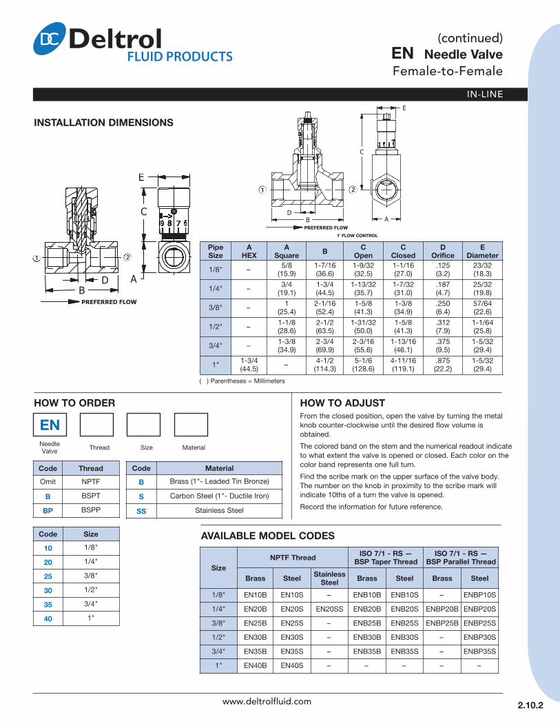
HOW TO ADjuSTFrom the closed position, open the valve by turning the metalknob counter-clockwise until the desired flow volume isobtained.
The colored band on the stem and the numerical readout indicateto what extent the valve is opened or closed. Each color on thecolor band represents one full turn.
Find the scribe mark on the upper surface of the valve body.The number on the knob in proximity to the scribe mark willindicate 10ths of a turn the valve is opened.
Record the information for future reference.
SizenPTF Thread ISO 7/1 - rS —
BSP Taper ThreadISO 7/1 - rS —
BSP Parallel Thread
Brass Steel StainlessSteel Brass Steel Brass Steel
1/8" EN10B EN10S – ENB10B ENB10S – ENBP10S
1/4" EN20B EN20S EN20SS ENB20B ENB20S ENBP20B ENBP20S
3/8" EN25B EN25S – ENB25B ENB25S ENBP25B ENBP25S
1/2" EN30B EN30S – ENB30B ENB30S – ENBP30S
3/4" EN35B EN35S – ENB35B ENB35S – ENBP35S
1" EN40B EN40S – – – – –
PipeSize
AHeX
ASquare B C
OpenC
ClosedD
Orificee
Diameter1/8" – 5/8
(15.9)1-7/16(36.6)
1-9/32(32.5)
1-1/16(27.0)
.125(3.2)
23/32(18.3)
1/4" – 3/4(19.1)
1-3/4(44.5)
1-13/32(35.7)
1-7/32(31.0)
.187(4.7)
25/32(19.8)
3/8" – 1(25.4)
2-1/16(52.4)
1-5/8(41.3)
1-3/8(34.9)
.250(6.4)
57/64(22.6)
1/2" – 1-1/8(28.6)
2-1/2(63.5)
1-31/32(50.0)
1-5/8(41.3)
.312(7.9)
1-1/64(25.8)
3/4" – 1-3/8(34.9)
2-3/4(69.9)
2-3/16(55.6)
1-13/16(46.1)
.375(9.5)
1-5/32(29.4)
1" 1-3/4(44.5) – 4-1/2
(114.3)5-1/6(128.6)
4-11/16(119.1)
.875(22.2)
1-5/32(29.4)
1 2
www.deltrolfluid.com
InSTALLATIOn DIMenSIOnS
1 2
n needle ValveFemale-to-Female
8-9 01/14
IN-LINE
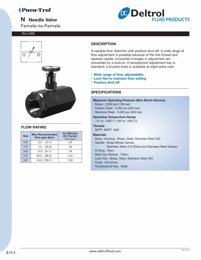
DeSCrIPTIOnA variable flow restrictor with positive shut-off. A wide range offlow adjustment is possible because of the fine thread andtapered needle. Unwanted changes in adjustment areprevented by a locknut. A tamperproof adjustment key isstandard; a knurled knob is available at slight extra cost.
• Wide range of flow adjustability• Lock nut to maintain flow setting• Positive shut-off
SPeCIFICATIOnS
Maximum Operating Pressure (non-Shock Service)Brass: 2,000 psi (138 bar)Carbon Steel: 5,000 psi (345 bar)Stainless Steel: 5,000 psi (345 bar)
Operating Temperature range-15° to +400° F (-26° to +204° C)
ThreadsNPTF, BSPT, SAE
MaterialsBody, Housing: Brass, Steel, Stainless Steel 303Needle: Brass (Brass Valves)
Stainless Steel 416 (Steel and Stainless Steel Valves)O-Ring: VitonBack-Up Washer: TeflonLock Nut: Brass, Steel, Stainless Steel 303Knob: AluminumTamperproof Key: Steel
Size Max recommendedFlow gpm (lpm)
Co-efficient(Cv Factor) Fully Open
1/8" 3.2 (12.1) .20
1/4" 7.0 (26.5) .43
3/8" 13.5 (51.1) .78
1/2" 22.5 (85.2) 1.24
3/4" 34.0 (128.7) 1.93
FLOW rATInG
2.11.1 www.deltrolfluid.com
IN-LINE
2.11.2
(continued)n needle Valve
Female-to-Female
InSTALLATIOn DIMenSIOnS
n
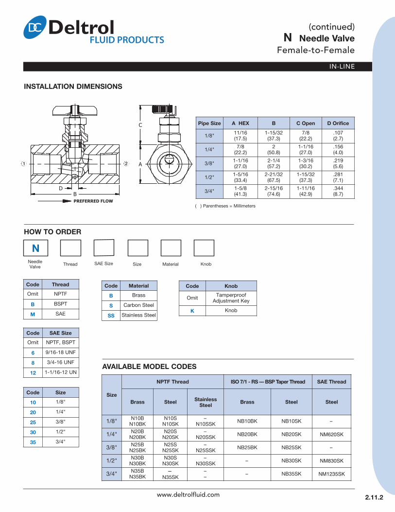
Code ThreadOmit NPTF
B BSPT
M SAE
Code Size10 1/8"
20 1/4"
25 3/8"
30 1/2"
35 3/4"
Code knob
Omit TamperproofAdjustment Key
k Knob
AVAILABLe MODeL CODeS
HOW TO OrDer
Size
nPTF Thread ISO 7/1 - rS –– BSP Taper Thread SAe Thread
Brass Steel StainlessSteel Brass Steel Steel
1/8" N10BN10BK
N10SN10SK
–N10SSK NB10BK NB10SK –
1/4" N20BN20BK
N20SN20SK
–N20SSK NB20BK NB20SK NM620SK
3/8" N25BN25BK
N25SN25SK
–N25SSK NB25BK NB25SK –
1/2" N30BN30BK
N30SN30SK
–N30SSK – NB30SK NM830SK
3/4" N35BN35BK
–N35SK
–– – NB35SK NM1235SK
( ) Parentheses = Millimeters
Pipe Size A HeX B C Open D Orifice
1/8" 11/16 (17.5)
1-15/32 (37.3)
7/8 (22.2)
.107 (2.7)
1/4" 7/8 (22.2)
2(50.8)
1-1/16(27.0)
.156 (4.0)
3/8" 1-1/16(27.0)
2-1/4(57.2)
1-3/16(30.2)
.219 (5.6)
1/2" 1-5/16(33.4)
2-21/32(67.5)
1-15/32 (37.3)
.281 (7.1)
3/4" 1-5/8(41.3)
2-15/16(74.6)
1-11/16 (42.9)
.344 (8.7)
Code MaterialB Brass
S Carbon Steel
SS Stainless Steel
21
www.deltrolfluid.com
Code SAe SizeOmit NPTF, BSPT
6 9/16-18 UNF
8 3/4-16 UNF
12 1-1/16-12 UN
NeedleValve Thread SAE Size Size Material Knob
MODEL 50
IN-LINE
S, SM needle Valve, High PressureMale-to-Female / Female-to-Female
16 02/14
2.15.1
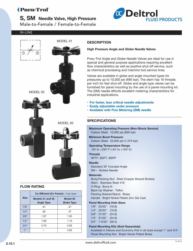
DeSCrIPTIOnHigh Pressure Angle and Globe needle Valves
Pneu-Trol Angle and Globe Needle Valves are ideal for use in special and general purpose applications requiring excellentflow characteristics as well as positive shut-off service, suchas chemical processing and machine tool service lines.
Valves are available in globe and angle mounted types for pressures up to 10,000 psi (690 bar). The stem has 16 threadsper inch for fast shut-off. Globe and angle type valves can befurnished for panel mounting by the use of a panel-mounting kit.The (SM) needle affords excellent metering characteristics forindustrial applications.
• For faster, less critical needle adjustments• easily adjustable under pressure• Available with Fine Metering (SM) needle
SPeCIFICATIOnS
Maximum Operating Pressure (non-Shock Service)Carbon Steel: 10,000 psi (690 bar)
Minimum Burst Pressure:Carbon Steel: 20,000 psi (1,379 bar)
Operating Temperature range-30° to +250° F (-34° to +120° C)
ThreadsNPTF, BSPT, BSPP
needleStandard 30˚ Included AngleSM – Slotted Needle
MaterialsBody/Packing Nut: Steel (Copper Brazed Bodies)Stem: Stainless Steel 416O-Ring: Buna-NBack-Up Washer: TeflonPacking Washer/Gland: BrassHandle: Bright Nickel Plated Zinc Die Cast
Panel Mounting Hole Sizes1/8" 25/32" (19.8)1/4" 25/32" (19.8)3/8" 31/32" (24.6)1/2" 31/32" (24.6)3/4" 1-5/32" (29.4)
Panel Mounting kits (Sold Separately)Available in Deluxe and Economy Kits in all sizes except 1" and 3/4".Panel Mounting Nut: Bright Nickel Plated Brass
MODEL 01
MODEL 02
FLOW rATInG
www.deltrolfluid.com
SizeCo-efficient (Cv Factor) - Fully Open
Models 01 and 02Angle Type
Model 50Globe Type
1/8" .67 .37
1/4" .85 .47
3/8" 1.67 1.00
1/2" 1.89 1.10
3/4" 3.70 2.65
1" – 4.65
IN-LINE
2.15.2
(continued)S, SM needle Valve, High PressureMale-to-Female / Female-to-Female
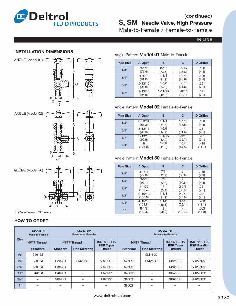
InSTALLATIOn DIMenSIOnS
HOW TO OrDer
Pipe Size A Open B C D Orifice
1/8" 3-1/8(79.4)
15/16(23.8)
15/16(23.8)
.188(4.8)
1/4" 3-3/16(81.0)
1-1/4(31.8)
1-1/8(28.6)
.188(4.8)
3/8" 3-13/16(96.9)
1-3/8(34.9)
1-1/4(31.8)
.281(7.1)
1/2" 3-13/16(96.9)
1-11/16(42.9)
1-9/16(39.7)
.281(7.1)
( ) Parentheses = Millimeters
Angle Pattern Model 01 Male-to-Female
Pipe Size A Open B C D Orifice
1/4" 3-23/64(85.3)
1-1/4(31.8)
1-1/8(28.6)
.188(4.8)
3/8" 3-13/16(96.9)
1-3/8(34.9)
1-1/4(31.8)
.281(7.1)
1/2" 3-13/16(96.9)
1-11/16(42.9)
1-9/16(39.7)
.281(7.1)
3/4" 5(127.0)
1-5/8(41.3)
1-3/4(44.5)
.438(11.1)
Angle Pattern Model 02 Female-to-Female
Pipe Size A Open B C D Orifice
1/8" 3-1/16(77.8)
7/8(22.2)
2(50.8)
.188(4.8)
1/4" 3-5/8(92.1)
7/8(22.2)
2(50.8)
.188(4.8)
3/8" 4-1/32(102.4)
1(25.4)
2-3/8(60.3)
.281(7.1)
1/2" 3-15/16(100.0)
1-1/4(31.8)
2-7/8(75.0)
.281(7.1)
3/4" 4-15/16(125.5)
1-1/2(38.1)
3-5/8(92.1)
.438(11.1)
1" 6-1/8(155.6)
2(50.8)
4(101.6)
.563(14.3)
Angle Pattern Model 50 Female-to-Female
Size
Model 01Male-to Female
Model 02Female-to Female
Model 50Female-to Female
nPTF Thread nPTF Thread ISO 7/1 – rSBSP Taper
Thread
nPTF Thread ISO 7/1 – rSBSP Taper
Thread
ISO 7/1 – rSBSP Parallel
ThreadStandard Standard Fine Metering Standard Fine Metering1/8" S101S1 – – – – SM150S1 – –
1/4" S201S1 S202S1 SM202S1 SB202S1 S250S1 SM250S1 SB250S1 SBP250S1
3/8" S301S1 S302S1 – SB302S1 S350S1 – SB350S1 SBP350S1
1/2" S401S1 S402S1 – SB402S1 S450S1 – SB450S1 SBP450S1
3/4" – S602S1 – SB602S1 S650S1 – SB650S1 SBP650S1
1" – – – – S850S1 – – –
ANGLE (Model 01)
ANGLE (Model 02)
GLOBE (Model 50)
www.deltrolfluid.com
1
2
1
2
1 2
IN-LINE
n MF
nMF needle ValveMale-to-Female
10 01/14
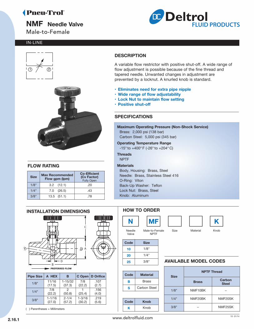
DeSCrIPTIOnA variable flow restrictor with positive shut-off. A wide range offlow adjustment is possible because of the fine thread andtapered needle. Unwanted changes in adjustment areprevented by a locknut. A knurled knob is standard.
• eliminates need for extra pipe nipple• Wide range of flow adjustability• Lock nut to maintain flow setting• Positive shut-off
SPeCIFICATIOnS
Maximum Operating Pressure (non-Shock Service)Brass: 2,000 psi (138 bar)Carbon Steel: 5,000 psi (345 bar)
Operating Temperature range-15° to +400° F (-26° to +204° C)
ThreadsNPTF
MaterialsBody, Housing: Brass, SteelNeedle: Brass, Stainless Steel 416O-Ring: VitonBack-Up Washer: TeflonLock Nut: Brass, SteelKnob: Aluminum
A
Pipe Size A HeX B C Open D Orifice
1/8" 11/16(17.5)
1-15/32 (37.3)
7/8 (22.2)
.107 (2.7)
1/4" 7/8(22.2)
2(50.8)
1(25.4)
.156 (4.0)
3/8" 1-1/16(27.0)
2-1/4(57.2)
1-3/16(30.2)
.219 (5.6)
( ) Parentheses = Millimeters
HOW TO OrDer
Code Size10 1/8"
20 1/4"
25 3/8"
Code Material
B Brass
S Carbon Steel
InSTALLATIOn DIMenSIOnS
2.16.1
k
Code knobk Knob
SizenPTF Thread
Brass CarbonSteel
1/8" NMF10BK –
1/4" NMF20BK NMF20SK
3/8" – NMF25SK
AVAILABLe MODeL CODeS
www.deltrolfluid.com
21
Size Max recommendedFlow gpm (lpm)
Co-efficient(Cv Factor) Fully Open
1/8" 3.2 (12.1) .20
1/4" 7.0 (26.5) .43
3/8" 13.5 (51.1) .78
FLOW rATInG
NeedleValve
Male-to-FemaleNPTF
Size Material Knob
IN-LINE
nMF20-10S needle ValveMale-to-Female
12 02/14
InSTALLATIOn DIMenSIOnS
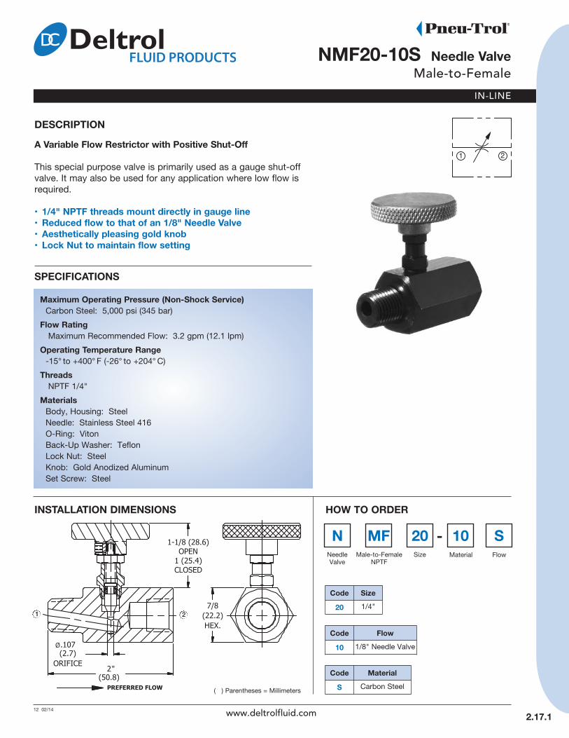
DeSCrIPTIOnA Variable Flow restrictor with Positive Shut-Off
This special purpose valve is primarily used as a gauge shut-offvalve. It may also be used for any application where low flow isrequired.
• 1/4" nPTF threads mount directly in gauge line• reduced flow to that of an 1/8" needle Valve• Aesthetically pleasing gold knob• Lock nut to maintain flow setting
SPeCIFICATIOnS
Maximum Operating Pressure (non-Shock Service)Carbon Steel: 5,000 psi (345 bar)
Flow ratingMaximum Recommended Flow: 3.2 gpm (12.1 lpm)
Operating Temperature range-15° to +400° F (-26° to +204° C)
ThreadsNPTF 1/4"
MaterialsBody, Housing: SteelNeedle: Stainless Steel 416O-Ring: VitonBack-Up Washer: TeflonLock Nut: SteelKnob: Gold Anodized AluminumSet Screw: Steel
2.17.1
n MF 20 10HOW TO OrDer
Code Size20 1/4"
S-
Code Flow10 1/8" Needle Valve
Code MaterialS Carbon Steel
1 2
www.deltrolfluid.com
( ) Parentheses = Millimeters
NeedleValve
Male-to-FemaleNPTF
Size Material Flow

IN-LINE
n20-10S needle ValveFemale-to-Female
12 02/14
DeSCrIPTIOnA Variable Flow restrictor with Positive Shut-Off
Ideally suited for use as a gauge shut-off valve, this right anglePneu-Trol needle valve has 1/4" NPTF threads that mount directlyinto the gauge line. Flow is reduced to that of 1/8" needle valvefor limited flow to gauge. This valve may also be used for low flowapplications.
• 1/4" nPTF threads mount directly in gauge line• reduced flow to that of an 1/8" needle Valve• Aesthetically pleasing gold knob• Lock nut to maintain flow setting
SPeCIFICATIOnS
Maximum Operating Pressure (non-Shock Service)Carbon Steel: 5,000 psi (345 bar)
Flow ratingMaximum Recommended Flow: 3.2 gpm (12.1 lpm)
Operating Temperature range-15° to +400° F (-26° to +204° C)
ThreadsNPTF 1/4"
MaterialsBody, Housing: SteelNeedle: Stainless Steel 416O-Ring: VitonBack-Up Washer: TeflonLock Nut: SteelKnob: Gold Anodized AluminumSet Screw: Steel
HOW TO OrDer
Code Size20 1/4" NPTF
Code Material
S Carbon Steel
InSTALLATIOn DIMenSIOnS
2.18.1
nNeedleValve Size Flow Material
20 10 S-
Code Flow10 1/8” Needle Valve
1
2
www.deltrolfluid.com
( ) Parentheses = Millimeters

IN-LINE
SFP Flow Control InstrumentationFemale-to-Female
7 01/14
DeSCrIPTIOnA Stainless Steel Instrumentation Flow Control Valve
A spring biased poppet check provides free flow in one direction.A fine metering tapered needle provides a range of adjustment in thecontrolled direction. A locknut prevents unwanted changes in adjustment.
• 316 Stainless Steel• Fine Metering• Bubble-Tight poppet-style check• T-Bar handle (removable if desired)• Lock nut to maintain flow setting• Ideal for food processing and petro chemical industries
SPeCIFICATIOnS
Maximum Operating PressureStainless Steel: 1,000 psi (69 bar) and
500 psi (34 bar)
Flow ratingMaximum Recommended Flow:1.5 gpm (5.7 lpm) & 3.0 gpm (11.4 lpm)
Operating Temperature range-15° to +400° F (-26° to +204° C)
ThreadsNPTF
( ) Parentheses = Millimeters
HOW TO OrDer
2.21.1
SizenPTF Thread rated
Pressurepsi (bar)
rated Flow
gpm (lpm)Stainless Steel
1/8" SFP10SSB 1,000 (69)
1.5 (5.7)
1/4" SFP20SSB 500 (34)
3.0 (11.4)
InSTALLATIOn DIMenSIOnS
1 2
Pipe Size A HeX B C Open D e Orifice
1/8" 11/16 (17.5)
1-3/4 (44.5)
7/8 (22.3)
3/16 (4.8)
.050(1.3)
1/4" 7/8(22.3)
2-3/8(60.4)
1-1/16 (27.0)
3/16 (4.8)
.062(1.6)
www.deltrolfluid.com
MaterialsBody, Housing: Stainless Steel 316Needle: Stainless Steel 316O-Ring: VitonBack-Up Washer: TeflonPoppet: Stainless Steel 316 withViton Quad Ring
Spring: Stainless Steel 316Lock Nut: Stainless Steel 316Handle: Stainless Steel 316Set Screw: Stainless Steel 303

8-9 02/14
F, FP Flow ControlFemale-to-Female
IN-LINE
DeSCrIPTIOnA Variable Flow restrictor with Positive Shut-Off and Freereverse Flow
A wide range of flow adjustment in the controlled flow direction ispossible because of the fine thread and tapered needle. A springbiased ball check or optional poppet check allows full flow inthe opposite direction. Unwanted changes in adjustment areprevented by a lock nut.
• A wide range of flow adjustability• Lock nut to maintain flow setting• Positive shut-off• Leak-Tight Ball Check standard• Bubble-Tight Poppet with O-ring optional
SPeCIFICATIOnS
Maximum Operating Pressure (non-Shock Service)Brass: 2,000 psi (138 bar)Carbon Steel: 5,000 psi (345 bar)Stainless Steel: 5,000 psi (345 bar)
Maximum Operating Pressure (Flow Control Poppet)60 psi (4 bar)
Cracking Pressure1 to 2.5 psi (.07 to .17 bar)Soft seat check valves if left seated for a period of time, will havethe rubber adhere to the metal it is in contact with. This results inan initial high crack point due to sticking. The degree depends onmany things (time seated, pressure, etc.).
Operating Temperature range-15° to +400° F (-26° to +204° C)
ThreadsNPTF, BSPT, SAE
MaterialsBody, Housing, Plug: Brass, Steel, Stainless Steel 303Needle: Brass (Brass Valves)
Stainless Steel 416 (Steel and Stainless Steel Valves)O-Ring: VitonBack-Up Washer: TeflonBall: Stainless Steel 440Spring: Stainless Steel 302Lock Nut: Brass, Steel, Stainless Steel 303Tamperproof Key: SteelKnob: Aluminum
Size Max recommendedFlow gpm (lpm)
Co-efficient(Cv Factor)
1/8" 1.5 (5.7) .23
1/4" 3.0 (11.4) .54
3/8"5.0 (18.9) .83
SAE 6
1/2" 8.0 (30.3) 1.47
3/4" 12.0 (45.4) 1.90
FLOW rATInG
www.deltrolfluid.com2.22 .1

IN-LINE
(continued)F, FP Flow Control
Female-to-Female
InSTALLATIOn DIMenSIOnS
F*
Code ThreadOmit NPTF
B BSPT
M SAE
Code Size
10 1/8"
20 1/4"
25 3/8"
30 1/2"
35 3/4"
Code knob
Omit TamperproofAdjustment Key
k Knob
AVAILABLe MODeL CODeS
HOW TO OrDer
SizenPTF Thread ISO 7/1 - rS –– BSP Taper Thread SAe Thread
Brass Steel StainlessSteel Brass Steel Steel
1/8"FP10BKF10BF10BK
F10SF10SK
–F10SSK FB10BK FB10SK –
1/4"FP20BKF20BF20BK
F20SF20SK
–F20SSK FB20BK FB20SK FM620S
FM620SK
3/8"FP25BKF25BF25BK
F25SF25SK
–F25SSK FB25BK FB25SK –
1/2" F30BF30BK
F30SF30SK
–F30SSK – FB30SK –
3/4" F35B– F35SK –
– – FB35SK –
( ) Parentheses = Millimeters
Series Thread SAE Size Size Material
Pipe Size A HeX B C Open D e Orifice
1/8" 11/16 (17.5)
1-3/4(44.5)
7/8 (22.2)
13/64 (5.2)
.107 (2.7)
1/4" 7/8 (22.2)
2-3/8(60.3)
1-1/16(27.0)
23/64(9.1)
.156 (4.0)
3/8" 1-1/16(27.0)
2-3/4(69.9)
1-3/16(30.2)
11/32(8.7)
.219 (5.6)
1/2" 1-5/16(33.4)
3-3/16(81.0)
1-15/32 (37.3)
15/32 (11.9)
.281 (7.1)
3/4" 1-5/8(41.3)
3-9/16(90.5)
1-11/16 (42.9)
17/32 (13.5)
.344 (8.7)
Code Series
F Flow Control
FP Flow Control Poppet
2 1
2.22.2
Code Material
B Brass
S Carbon Steel
SS Stainless Steel
www.deltrolfluid.com
Code SAe Size
Omit NPTF, BSPT
6 9/16-18 UNF
Knob

IN-LINE
F MF B
FMF Flow ControlMale-to-Female
10 03/14
DeSCrIPTIOnA Variable Flow restrictor with Positive Shut-Off and Freereverse Flow
A wide range of flow adjustment in the controlled flow direction ispossible because of the fine thread and tapered needle. A springbiased ball check allows full flow in the opposite direction.Unwanted changes in adjustment are prevented by a lock nut.
• A wide range of flow adjustability• Lock nut to maintain flow setting• Positive shut-off• eliminates need for extra pipe nipple
SPeCIFICATIOnS
Maximum Operating Pressure(non-Shock Service)Brass: 2,000 psi (138 bar)
Cracking Pressure1 to 2.5 psi (.07 to .17 bar)
Operating Temperature range-15° to +400° F (-26° to +204° C)
ThreadsNPTF
Pipe Size A HeX B C D e Orifice1/8" 11/16
(17.5)1-3/4(44.5)
7/8(22.2)
13/64(5.2)
.107(2.7)
1/4" 7/8(22.2)
2-3/8(60.3)
1-1/16(27.0)
23/64(9.1)
.156(4.0)
3/8" 1-1/16 (27.0)
2-3/4 (69.9)
1-3/16(30.2)
11/32(8.7)
.219 (5.6)
1/2" 1-5/16 (33.4)
3-3/16(81.0)
1-15/32(37.3)
15/32(11.9)
.281 (7.1)
( ) Parentheses = Millimeters
HOW TO OrDer
Code Size10 1/8"
20 1/4"
25 3/8"
30 1/2"
Code Material
B Brass
InSTALLATIOn DIMenSIOnS
2.23.1
k
Code knobk Knob
SizenPTF Thread
Brass1/8" FMF10BK
1/4" FMF20BK
3/8" FMF25BK
1/2" FMF30BK
AVAILABLe MODeL CODeS
21
www.deltrolfluid.com
Size Max recommendedFlow gpm (lpm)
Co-efficient(Cv Factor)
1/8" 1.5 (5.7) .23
1/4" 3.0 (11.4) .54
3/8" 5.0 (18.9) .83
1/2" 8.0 (30.3) 1.47
FLOW rATInGMaterialsBody, Housing, Plug: BrassCollar: Stainless Steel 303Needle: BrassO-Ring: VitonBack-Up Washer: TeflonBall: Stainless Steel 440Spring: Stainless Steel 302Lock Nut: BrassKnob: Aluminum
FlowControl
Male-to-FemaleNPTF Size Material Knob
IN-LINE
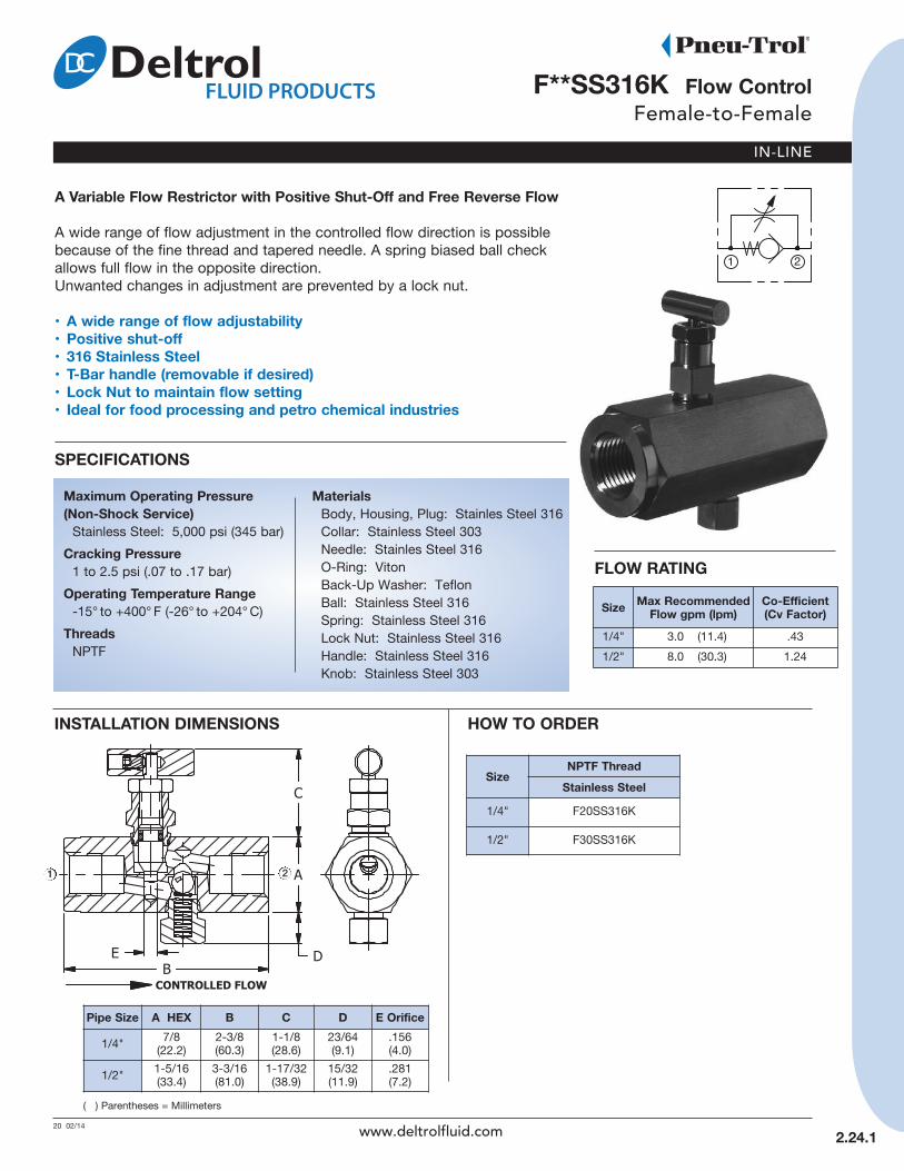
F**SS316k Flow ControlFemale-to-Female
20 02/14
A Variable Flow restrictor with Positive Shut-Off and Free reverse Flow
A wide range of flow adjustment in the controlled flow direction is possiblebecause of the fine thread and tapered needle. A spring biased ball checkallows full flow in the opposite direction.Unwanted changes in adjustment are prevented by a lock nut.
• A wide range of flow adjustability• Positive shut-off• 316 Stainless Steel• T-Bar handle (removable if desired)• Lock nut to maintain flow setting• Ideal for food processing and petro chemical industries
SPeCIFICATIOnS
Maximum Operating Pressure(non-Shock Service)Stainless Steel: 5,000 psi (345 bar)
Cracking Pressure1 to 2.5 psi (.07 to .17 bar)
Operating Temperature range-15° to +400° F (-26° to +204° C)
ThreadsNPTF
( ) Parentheses = Millimeters
HOW TO OrDer
2.24.1
SizenPTF Thread
Stainless Steel1/4" F20SS316K
1/2" F30SS316K
InSTALLATIOn DIMenSIOnS
1
Pipe Size A HeX B C D e Orifice
1/4" 7/8 (22.2)
2-3/8 (60.3)
1-1/8 (28.6)
23/64 (9.1)
.156 (4.0)
1/2" 1-5/16 (33.4)
3-3/16(81.0)
1-17/32(38.9)
15/32 (11.9)
.281 (7.2)
2
www.deltrolfluid.com
MaterialsBody, Housing, Plug: Stainles Steel 316Collar: Stainless Steel 303Needle: Stainles Steel 316O-Ring: VitonBack-Up Washer: TeflonBall: Stainless Steel 316Spring: Stainless Steel 316Lock Nut: Stainless Steel 316Handle: Stainless Steel 316Knob: Stainless Steel 303
Size Max recommendedFlow gpm (lpm)
Co-efficient(Cv Factor)
1/4" 3.0 (11.4) .43
1/2" 8.0 (30.3) 1.24
FLOW rATInG
IN-LINE
3-5 02/14
2.25.1
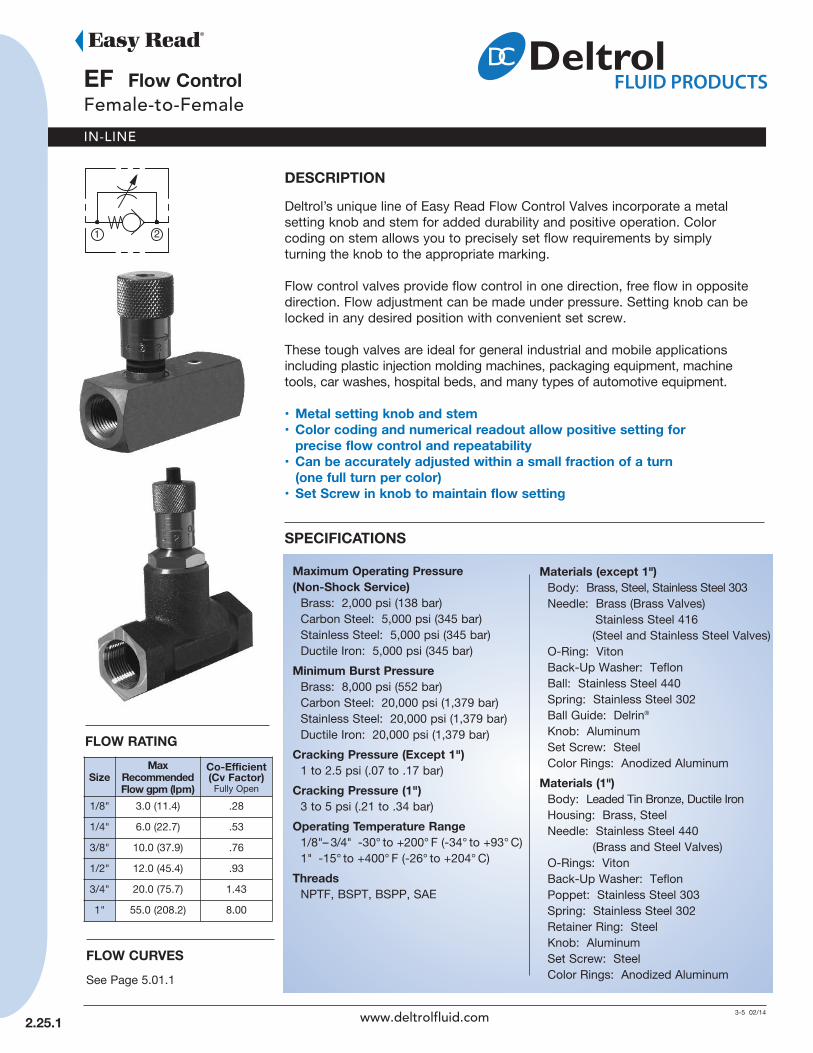
eF Flow ControlFemale-to-Female
DeSCrIPTIOnDeltrol’s unique line of Easy Read Flow Control Valves incorporate a metalsetting knob and stem for added durability and positive operation. Colorcoding on stem allows you to precisely set flow requirements by simplyturning the knob to the appropriate marking.
Flow control valves provide flow control in one direction, free flow in oppositedirection. Flow adjustment can be made under pressure. Setting knob can belocked in any desired position with convenient set screw.
These tough valves are ideal for general industrial and mobile applicationsincluding plastic injection molding machines, packaging equipment, machinetools, car washes, hospital beds, and many types of automotive equipment.
• Metal setting knob and stem• Color coding and numerical readout allow positive setting for
precise flow control and repeatability• Can be accurately adjusted within a small fraction of a turn
(one full turn per color)• Set Screw in knob to maintain flow setting
SPeCIFICATIOnS
Maximum Operating Pressure(non-Shock Service)Brass: 2,000 psi (138 bar)Carbon Steel: 5,000 psi (345 bar)Stainless Steel: 5,000 psi (345 bar)Ductile Iron: 5,000 psi (345 bar)
Minimum Burst PressureBrass: 8,000 psi (552 bar)Carbon Steel: 20,000 psi (1,379 bar)Stainless Steel: 20,000 psi (1,379 bar)Ductile Iron: 20,000 psi (1,379 bar)
Cracking Pressure (except 1")1 to 2.5 psi (.07 to .17 bar)
Cracking Pressure (1")3 to 5 psi (.21 to .34 bar)
Operating Temperature range1/8"– 3/4" -30° to +200° F (-34° to +93° C)1" -15° to +400° F (-26° to +204° C)
ThreadsNPTF, BSPT, BSPP, SAE
FLOW rATInG
SizeMax
recommended Flow gpm (lpm)
Co-efficient(Cv Factor) Fully Open
1/8" 3.0 (11.4) .28
1/4" 6.0 (22.7) .53
3/8" 10.0 (37.9) .76
1/2" 12.0 (45.4) .93
3/4" 20.0 (75.7) 1.43
1" 55.0 (208.2) 8.00
FLOW CurVeSSee Page 5.01.1
www.deltrolfluid.com
Materials (except 1")Body: Brass, Steel, Stainless Steel 303Needle: Brass (Brass Valves)
Stainless Steel 416(Steel and Stainless Steel Valves)
O-Ring: VitonBack-Up Washer: TeflonBall: Stainless Steel 440Spring: Stainless Steel 302Ball Guide: Delrin®
Knob: AluminumSet Screw: SteelColor Rings: Anodized Aluminum
Materials (1")Body: Leaded Tin Bronze, Ductile IronHousing: Brass, SteelNeedle: Stainless Steel 440
(Brass and Steel Valves)O-Rings: VitonBack-Up Washer: TeflonPoppet: Stainless Steel 303Spring: Stainless Steel 302Retainer Ring: SteelKnob: AluminumSet Screw: SteelColor Rings: Anodized Aluminum

IN-LINE
2.25.2
(continued)eF Flow ControlFemale-to-Female
Code ThreadOmit NPTF
B BSPT
BP BSPP
M SAE
Code Size10 1/8"
20 1/4"
25 3/8"
30 1/2"
35 3/4"
40 1"
Code MaterialB Brass (1"- Leaded Tin Bronze)
S Carbon Steel (1"- Ductile Iron)
SS Stainless Steel
( ) Parentheses = Millimeters
AVAILABLe MODeL CODeS
HOW TO OrDer
eFFlowControl Thread SAE Size Size
HOW TO ADjuSTFrom the closed position, open the valve by turning the metalknob counter-clockwise until the desired flow volume isobtained.
The colored band on the stem and the numerical readoutindicate to what extent the valve is opened or closed. Eachcolor on the color band represents one full turn.
Find the scribe mark on the upper surface of the valve body.The number on the knob in proximity to the scribe mark willindicate 10ths of a turn the valve is opened.
Record the information for future reference.
SizenPTF Thread ISO 7/1 - rS —
BSP Taper ThreadISO 7/1 - rP —
BSP Parallel ThreadSAe
Thread
Brass Steel StainlessSteel Brass Steel Brass Steel Carbon
Steel1/8" EF10B EF10S EF10SS EFB10B EFB10S EFBP10B EFBP10S –
1/4" EF20B EF20S EF20SS EFB20B EFB20S EFBP20B EFBP20S EFM620S
3/8" EF25B EF25S EF25SS EFB25B EFB25S EFBP25B EFBP25S EFM825S
1/2" EF30B EF30S EF30SS EFB30B EFB30S EFBP30B EFBP30S EFM1030S
3/4" EF35B EF35S – EFB35B EFB35S – EFBP35S EFM1235S
1" EF40B EF40S – – – – – –
PipeSize
ASquare
A SAeSquare
AHeX B B
SAeB
ISOC
OpenC
ClosedD
Orificee
Diameter1/8" 5/8
(15.9) – – 1-15/16(49.2) – 1-15/16
(49.2)1-9/32(32.5)
1-1/16(27.0)
.125(3.7)
23/32(18.3)
1/4" 3/4(19.1)
3/4(19.1) – 2-13/32
(61.1)2-9/16(65.1)
2-1/2(63.5)
1-13/32(35.7)
1-7/32(31.0)
.187(9.7)
25/32(19.8)
3/8" 1(25.4)
1-1/8(28.6) – 2-7/8
(73.1)3-1/4(82.6)
2-31/32(75.4)
1-5/8(41.3)
1-3/8(39.9)
.250(6.4)
57/64(22.6)
1/2" 1-1/8(28.6)
1-1/4(31.8) – 3-7/16
(87.4)3-9/16(90.5)
3-7/16(87.4)
1-31/32(50.0)
1-5/8(41.3)
.312(7.9)
1-1/64(25.8)
3/4" 1-3/8(34.9)
1-1/2(38.1) – 3-3/4
(95.3)4-1/8(104.8)
3-3/4(95.3)
2-3/16(55.6)
1-13/16(46.1)
.375(9.5)
1-5/32(29.4)
1" – – 1-3/4(44.5)
4-1/2(114.3) – – 5-1/16
(128.6)4-11/16(119.1)
.875(22.2)
1-5/32(29.4)
www.deltrolfluid.com
InSTALLATIOn DIMenSIOnS
Code SAe Size
Omit NPTF, BSPT,BSPP
6 9/16-18 UNF
8 3/4-16 UNF
10 7/8-14 UNF
12 1-1/16-12 UN
12 21
Material
IN-LINE
14-15 02/14
2.30.1
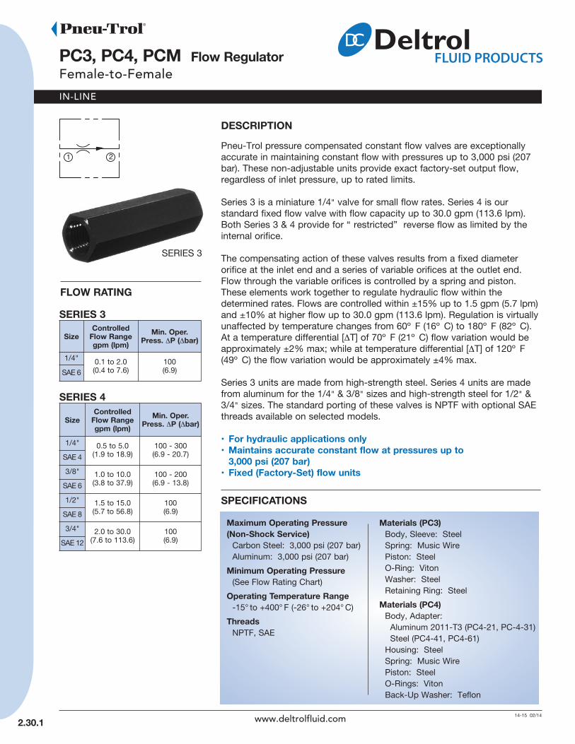
PC3, PC4, PCM Flow regulatorFemale-to-Female
DeSCrIPTIOnPneu-Trol pressure compensated constant flow valves are exceptionallyaccurate in maintaining constant flow with pressures up to 3,000 psi (207bar). These non-adjustable units provide exact factory-set output flow,regardless of inlet pressure, up to rated limits.
Series 3 is a miniature 1/4" valve for small flow rates. Series 4 is our standard fixed flow valve with flow capacity up to 30.0 gpm (113.6 lpm).Both Series 3 & 4 provide for “ restricted” reverse flow as limited by theinternal orifice.
The compensating action of these valves results from a fixed diameter orifice at the inlet end and a series of variable orifices at the outlet end.Flow through the variable orifices is controlled by a spring and piston.These elements work together to regulate hydraulic flow within the determined rates. Flows are controlled within ±15% up to 1.5 gpm (5.7 lpm)and ±10% at higher flow up to 30.0 gpm (113.6 lpm). Regulation is virtuallyunaffected by temperature changes from 60º F (16º C) to 180º F (82º C).At a temperature differential [ΔT] of 70º F (21º C) flow variation would beapproximately ±2% max; while at temperature differential [ΔT] of 120º F(49º C) the flow variation would be approximately ±4% max.
Series 3 units are made from high-strength steel. Series 4 units are madefrom aluminum for the 1/4" & 3/8" sizes and high-strength steel for 1/2" &3/4" sizes. The standard porting of these valves is NPTF with optional SAEthreads available on selected models.
• For hydraulic applications only• Maintains accurate constant flow at pressures up to
3,000 psi (207 bar)• Fixed (Factory-Set) flow units
SPeCIFICATIOnS
Maximum Operating Pressure(non-Shock Service)Carbon Steel: 3,000 psi (207 bar)Aluminum: 3,000 psi (207 bar)
Minimum Operating Pressure(See Flow Rating Chart)
Operating Temperature range-15° to +400° F (-26° to +204° C)
ThreadsNPTF, SAE
SizeControlled
Flow rangegpm (lpm)
Min. Oper.Press. ΔP (Δbar)
1/4" 0.1 to 2.0(0.4 to 7.6)
100(6.9)SAE 6
FLOW rATInG
SizeControlled
Flow rangegpm (lpm)
Min. Oper.Press. ΔP (Δbar)
1/4" 0.5 to 5.0(1.9 to 18.9)
100 - 300(6.9 - 20.7)SAE 4
3/8" 1.0 to 10.0(3.8 to 37.9)
100 - 200(6.9 - 13.8)SAE 6
1/2" 1.5 to 15.0(5.7 to 56.8)
100(6.9)SAE 8
3/4" 2.0 to 30.0(7.6 to 113.6)
100(6.9)SAE 12
SerIeS 3
SerIeS 4
SERIES 3
www.deltrolfluid.com
Materials (PC3)Body, Sleeve: SteelSpring: Music WirePiston: SteelO-Ring: VitonWasher: SteelRetaining Ring: Steel
Materials (PC4)Body, Adapter:Aluminum 2011-T3 (PC4-21, PC-4-31)Steel (PC4-41, PC4-61)
Housing: SteelSpring: Music WirePiston: SteelO-Rings: VitonBack-Up Washer: Teflon

IN-LINE
2.30.2
Code Series3 Miniature
4 Standard
InSTALLATIOn DIMenSIOnS
( ) Parentheses = Millimeters
HOW TO OrDer
PCFlow
RegulatorThread Series Size Flow Rate
gpm
Size A HeX B1/4"-SAE 4 1 (25.4) 3 (76.2)
3/8"-SAE 6 1-3/8 (34.9) 3-7/8 (98.4)
1/2"-SAE 8 1-1/2 (38.1) 4-1/4 (108.0)
3/4" 1-5/8 (41.3) 4-19/32 (116.7)
SAE 12 1-5/8 (41.3) 4-7/8 (123.8)
(continued)PC3, PC4, PCM Flow regulator
Female-to-Female
Series 3Miniature Fixed - with Restricted Reverse Flow
Series 4Standard Fixed - with Restricted Reverse Flow
Code ThreadOmit NPT
M4 SAE 4
M6 SAE 6
M8 SAE 8
M12 SAE 12
CodeSize
nPT SAe2 1/4" SAE 6
21 1/4" SAE 4
31 3/8" SAE 6
41 1/2" SAE 8
61 3/4" SAE 12
Series 3 only
PC3 Only PC4 PC4 PC4 PC41/4" 1/4" 3/8" 1/2" 3/4"
gpm lpm gpm lpm gpm lpm gpm lpm gpm lpm0.10 0.38 0.50 1.90 1.00 3.79 1.50 5.68 2.00 7.570.15 0.57 0.75 2.84 1.20 4.55 3.00 11.36 2.50 9.470.20 0.76 0.90 3.41 1.50 5.68 3.50 13.25 3.00 11.360.30 1.14 1.00 3.79 2.00 7.57 3.75 14.20 3.50 13.250.40 1.52 1.25 4.74 2.25 8.52 4.00 15.14 4.00 15.140.05 1.90 1.30 4.92 2.50 9.47 4.50 17.04 4.50 17.040.60 2.28 1.50 5.68 3.00 11.36 5.00 18.93 5.00 18.930.75 2.84 1.75 6.63 3.25 12.30 5.50 20.82 6.00 22.711.00 3.79 2.00 7.57 3.50 13.25 6.00 22.71 7.00 26.501.25 4.74 2.50 9.47 4.00 15.14 7.00 26.50 8.00 30.281.50 5.68 2.80 10.60 5.00 18.93 7.50 28.39 9.00 34.071.75 6.63 3.00 11.36 6.00 22.71 8.50 32.18 10.00 37.862.00 7.57 3.50 13.25 6.25 23.66 9.00 34.07 12.00 45.42
4.00 15.14 7.00 26.50 10.00 37.86 14.00 52.995.00 18.93 8.00 30.28 11.00 41.64 16.00 60.56
9.00 34.07 12.00 45.42 18.00 68.1310.00 37.86 13.00 49.21 20.00 75.70
14.00 52.99 22.00 83.2715.00 56.78 24.00 90.84
26.00 98.4128.00 105.9830.00 113.55
1 2
Size nPT Thread Flow range gpm (lpm)
1/4"PC3-2-gpm 0.1 to 2.0 (0.4 to 7.6)
PC4-21-gpm 0.5 to 5.0 (1.9 to 18.9)
3/8" PC4-31-gpm 1.0 to 10.0 (3.8 to 37.9)
1/2" PC4-41-gpm 1.5 to 15.0 (5.7 to 56.8)
3/4" PC4-61-gpm 2.0 to 30.0 (7.6 to 113.6)
Size SAe Thread Flow range gpm (lpm)SAE 4 PCM44-21-gpm 0.5 to 5.0 (1.9 to 18.9)
SAE 6PCM63-2-gpm 0.1 to 2.0 (0.4 to 7.6)
PCM64-31-gpm 1.0 to 10.0 (3.8 to 37.9)
SAE 8 PCM84-41-gpm 1.5 to 15.0 (5.7 to 56.8)
SAE 12 PCM124-61-gpm 2.0 to 30.0 (7.6 to 113.6)
AVAILABLe FLOW rATeS By SIzeAVAILABLe MODeL CODeS
www.deltrolfluid.com
Note: PC3s & PC4s are NOT stocked as complete or finished units.All “Fixed” units are drilled to suit each customer’s order “after” receipt.
1 2

IN-LINE
CV4.13 12 02/14
2.40.1
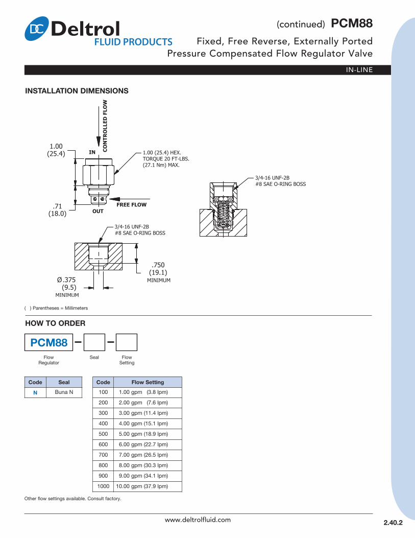
PCM88Fixed, Free Reverse, Externally PortedPressure Compensated Flow Regulator Valve
DeSCrIPTIOnA fixed cartridge valve designed to regulate flow regardless of load pressure. This valve is a restrictive-type flow regulatordesigned for a wide variety of flow applications.
The male outlet port allows for quick installation into existing manifolds for meter-in control with free flow in the opposite direction.
The PCM 88 maintains a constant flow within specified accuraciesfrom inlet to outlet regardless of downstream load pressure. Whenflow produces a minimum predetermined pressure differential acrossthe compensator spool control orifice, the spool shifts against thespring force to throttle the flow and maintain the flow setting. In thereverse direction the spool shifts to permit free flow.
• Pressure-compensated• Quiet response• Free reverse flow• Industry common cavity• Compact size
SPeCIFICATIOnS
Maximum Operating Pressure (non-Shock Service)Carbon Steel: 3,000 psi (207 bar)
Minimum Operating Pressure75 Δpsi (5.2 Δbar)
Flow range1.0 to 10.0 gpm (3.8 to 37.9 lpm)(See ordering table)
Flow Tolerances Flows up to and including 1.5 gpm (5.7 lpm) ±15%Flows over 1.5 gpm (5.7 lpm) ±10%
Operating Temperature range-30° to +250° F (-34° to +120° C)
recommended FiltrationISO 17/15/13
FluidsMineral-based fluids. For other fluid compatibility, consult factory.
Cavity#8 SAE, see page 2.40.2Also works in 080-2 Cartridge Valve Cavity
MaterialsHousing: SteelO-Ring: Buna-NSpring: Music WireSpool: SteelLock Screw: Steel
PreSSure DrOP VS. FLOW
FLOW CURVES TYP. FOR OTHER SIZES
REVERSE FLOW gpm(L/min.)
FLO
W g
pm (L
/min.
)
www.deltrolfluid.com
IN-LINE
InSTALLATIOn DIMenSIOnS
PCM88
Code Flow Setting100 1.00 gpm (3.8 lpm)
200 2.00 gpm (7.6 lpm)
300 3.00 gpm (11.4 lpm)
400 4.00 gpm (15.1 lpm)
500 5.00 gpm (18.9 lpm)
600 6.00 gpm (22.7 lpm)
700 7.00 gpm (26.5 lpm)
800 8.00 gpm (30.3 lpm)
900 9.00 gpm (34.1 lpm)
1000 10.00 gpm (37.9 lpm)
HOW TO OrDer
( ) Parentheses = Millimeters
Seal FlowSetting
Code Sealn Buna N
2.40.2
(continued) PCM88Fixed, Free Reverse, Externally Ported
Pressure Compensated Flow Regulator Valve
FlowRegulator
Other flow settings available. Consult factory.
www.deltrolfluid.com

IN-LINE
14-15 03/14
2.51 .1
PC*5 Flow regulatorFemale-to-Female
DeSCrIPTIOnPneu-Trol pressure compensated constant flow regulator valvesare exceptionally accurate in maintaining constant flow withpressures up to 3,000 psi (207 bar). These adjustable valves,while under pressure, allow infinite output flow adjustment withina specified flow range independent of inlet pressure variations.An internal check valve to bypass the control orifice providesunrestricted free reverse flow.
The compensating action of these valves results from anadjustable orifice at the inlet end and a series of variable orificesat the outlet end. Flow through the variable orifices is controlledby a spring and piston. These elements work together to regulatehydraulic flow within the determined rates. Flows are controlledwithin ±15% up to 1.5 gpm (5.7 lpm) and ±10% at higher flow upto 15.0 gpm (56.8 lpm). Regulation is virtually unaffected by tem-perature changes from 60º F (16º C) to 180º F (82º C). At a tem-perature differential [ΔT] of 70º F (21º C) flow variation would beapproximately ±2% max; while at temperature differential [ΔT] of120º F (49º C) the flow variation would be approximately ±4%max.
Series 5 units are made from high-strength steel. The standardporting of these valves is NPTF with optional SAE and BSPTthreads available on selected models.
• Maintains accurate constant flow at pressures up to 3,000 PSI (207 Bar)
• Adjustable flow• Lock nut to maintain flow setting • Free reverse flow
SPeCIFICATIOnS
Maximum Operating Pressure(non-Shock Service)Carbon Steel: 3,000 psi (207 bar)
Minimum Operating Pressure(See Flow Rating Chart)
Operating Temperature range-15° to +400° F (-26° to +204° C)
ThreadsNPTF, BSPT, SAE
SizeControlled
Flow rangegpm (lpm)
Min. Oper.Press. ΔP (Δbar)
1/4" 0.75 to 5.0(2.8 to 18.9)
100 - 300(6.9 to 20.7)
3/8" 1.0 to 10.0(3.8 to 37.9)
100 - 200(6.9 to 13.8)
1/2" 1.5 to 15.0(5.7 to 56.8)
200(13.8)
FLOW rATInGSerIeS 5 NPT Thread
SizeControlled
Flow rangegpm (lpm)
Min. Oper.Press. ΔP (Δbar)
1/4" 0.75 to 5.0(2.8 to 18.9)
100 - 300(6.9 to 20.7)
3/8" 1.0 to 10.0(3.8 to 37.9)
100 - 200(6.9 to 13.8)
1/2" 1.5 to 15.0(5.7 to 56.8)
200(13.8)
ISO 7/1 - RS – BSP Taper Thread
SizeControlled
Flow rangegpm (lpm)
Min. Oper.Press. ΔP (Δbar)
SAE 8(Size 3)
1.0 to 10.0(3.8 to 37.9)
100 - 200(6.9 to 13.8)
SAE 8(Size 4)
1.5 to 15.0(5.7 to 56.8)
200(13.8)
SAE Thread
www.deltrolfluid.com
MaterialsBody, Adapter:Clear, Zinc-Plated Steel
Spring: Music WirePiston: SteelHousing: BrassNeedle: Stainless Steel 416O-Rings: VitonBack-Up Washer: TeflonLock Nut: Stainless Steel 303Knob: Blue Anodized Aluminum

IN-LINE
(continued)PC*5 Flow regulator
Female-to-Female
InSTALLATIOn DIMenSIOnS
PC
Code ThreadOmit NPT
B BSPT
M8 SAE 8
CodeSize
nPTF/BSPT SAe2 1/4" –
3 3/8" SAE 8
4 1/2" SAE 8
HOW TO OrDer
( ) Parentheses = Millimeters
FlowRegulator
Thread Series Size
PipeSize A HeX B C
OpenC
Closed
1/4" 1-1/8 (28.6)
3-3/16 (81.0)
57/64 (22.6)
49/64(19.5)
3/8" 1-1/2 (38.1)
3-3/4(95.3)
1-5/32(29.4)
15/16(23.8)
1/2" 1-5/8(41.3)
4-3/8(111.1)
1-15/32(37.3)
1-7/32(31.0)
2.51.2
5
1 2
AVAILABLe MODeL CODeS
Size nPTF Thread ISO 7/1 - rS — BSP Taper Thread SAe Thread Flow range
gpm (lpm)Min. Oper.Press. ΔP
(Δbar)
1/4" PC5-2 PCB5-2 – 0.75 to 5.0(2.8 to 18.9)
100 - 300(6.9 to 20.7)
3/8" PC5-3 PCB5-3 – 1.0 to 10.0(3.8 to 37.9)
100 - 200(6.9 to 13.8)
1/2" PC5-4 PCB5-4 – 1.5 to 15.0(5.7 to 56.8)
200(13.8)
SAE 8– – PCM85-3 1.0 to 10.0
(3.8 to 37.9)100 - 200(6.9 to 13.8)
– – PCM85-4 1.5 to 15.0(5.7 to 56.8)
200(13.8)
www.deltrolfluid.com

IN-LINE
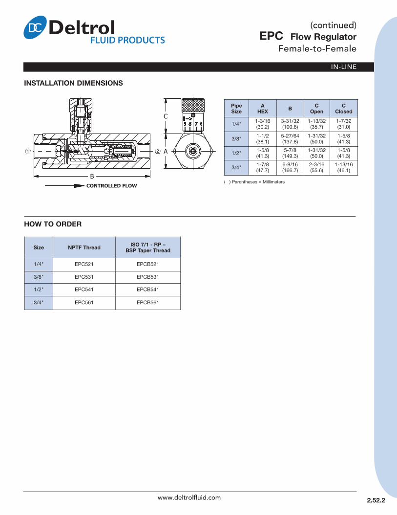
ePC Flow regulatorFemale-to-Female
6 02/14
DeSCrIPTIOnEasy Read pressure compensated constant flow regulator valvesare exceptionally accurate in maintaining constant flow withpressures up to 3,000 psi (207 bar). These adjustable valves,while under pressure, allow infinite output flow adjustment withina specified flow range independent of inlet pressure variations.An internal check valve to bypass the control orifice providesunrestricted free reverse flow.
The compensating action of these valves results from anadjustable orifice at the inlet end and a series of variable orificesat the outlet end. Flow through the variable orifices is controlledby a spring and piston. These elements work together to regulatehydraulic flow within the determined rates. Flows are controlledwithin ±15% up to 1.5 gpm (5.7 lpm) and ±10% at higher flow upto 15.0 gpm (56.8 lpm). Valves will start to control flow at 60/70psi (4.1/4.8 bar) pressure drop. Regulation is virtually unaffectedby temperature changes from 60º F (16º C) to 180º F (82º C).At a temperature differential [ΔT] of 70º F (21º C) flow variationwould be approximately ±2% max; while at temperature differential[ΔT] of 120º F (49º C) the flow variation would be approximately±4% max.
Metal setting knob and stem provide added durability for positiveoperation of valve in harsh industrial environments. Color codedstem plus numerical read-out ensures accurate setting for precisepressure compensated flow control and repeatability.
• Maintains accurate, constant flow at pressures up to3,000 psi (207 bar)
• Metal setting knob and stem to adjust flow• Positive position setting for precise flow control and
easy repeatability • Set Screw in knob to maintain flow setting• Low pressure drop in free reverse
SPeCIFICATIOnS
Maximum Operating PressureCarbon Steel: 3,000 psi (207 bar)
Minimum Operating Pressure(See Flow Rating Chart)
Operating Temperature range-15° to +400° F (-26° to +204° C)
ThreadsNPTF, BSPT
2.52.1 www.deltrolfluid.com
SizeControlled
Flow rangegpm (lpm)
Minimum Oper.Pressure ΔP (Δbar)
1/4" 0.5 - 5.0(1.9 - 18.9)
60(4.1)
3/8" 1.0 - 10.0 (3.8 - 37.9)
70(4.8)
1/2" 1.5 - 15.0(5.7 - 56.8)
70(4.8)
3/4" 3.0 - 30.0(11.4 - 113.6)
70(4.8)
FLOW rATInG
MaterialsBody: SteelNeedle: Stainless SteelO-Ring: VitronWasher: TeflonKnob: AluminumPiston: SteelSpring: Music Wire
IN-LINE
( ) Parentheses = Millimeters
Size nPTF Thread ISO 7/1 - rP –BSP Taper Thread
1/4" EPC521 EPCB521
3/8" EPC531 EPCB531
1/2" EPC541 EPCB541
3/4" EPC561 EPCB561
HOW TO OrDer
PipeSize
A HeX B C
OpenC
Closed
1/4" 1-3/16 (30.2)
3-31/32 (100.8)
1-13/32 (35.7)
1-7/32 (31.0)
3/8" 1-1/2 (38.1)
5-27/64 (137.8)
1-31/32 (50.0)
1-5/8 (41.3)
1/2" 1-5/8 (41.3)
5-7/8 (149.3)
1-31/32 (50.0)
1-5/8 (41.3)
3/4" 1-7/8 (47.7)
6-9/16 (166.7)
2-3/16 (55.6)
1-13/16 (46.1)
InSTALLATIOn DIMenSIOnS
2.52.2
21
www.deltrolfluid.com
(continued)ePC Flow regulator
Female-to-Female

POV32S Directional ValveFemale-to-Female
DeSCrIPTIOnThe Pneu-Trol plunger operated two-way valve controls hydraulic orpneumatic flow. This valve is normally closed and allows through flowwhen the plunger is manually depressed. The spring returned plungerblocks flow in the opposite direction.
• Soft Seat for positive shut-off• Panel or bracket mountable
SPeCIFICATIOnS
Maximum Operating Pressure(non-Shock Service)Carbon Steel: 3,000 psi (207 bar)
Operating Temperature range-15° to +400° F (-26° to +204° C)
Flow ratingCo-Efficient (Cv Factor) = 2.6
Plunger effort97 lbs. (431 N) per 1,000 psi (69 bar)
ThreadsNPTF 1/2"
Stroke1/2" (12.7)
Panel Mounting Hole Size31/32" (24.6)
S
( ) Parentheses = Millimeters
HOW TO OrDer
Size nPTFThread
Co-efficient(Cv Factor)
1/2" POV32S 2.6
InSTALLATIOn DIMenSIOnS
2
1
MaterialsBody, Plug: SteelSpring: Music WirePlunger: Stainless Steel 416 withUrethane O-Ring
O-Rings: VitonBack-Up Washer: TeflonPanel Mount Nuts: Nickel Plated Brass
7 02/14
3.01.1 www.deltrolfluid.com
IN-LINE

IN-LINE
7 02/14
3.02.1www.deltrolfluid.com
DeSCrIPTIOnA toggle-operated two-way valve designed with positive shut off.The TV20B can be actuated by pushing or pulling the toggle andwill over-center detent open.
• Bubble-Tight operation• Push or pull to operate – spring return• Over-Center detent capable• Panel or bracket mountable• Handle hole for cable mount
SPeCIFICATIOnS
Maximum Operating PressureBrass: 2,000 psi (138 bar)
reverse Cracking Pressure370 psi (26 bar)
Maximum recommended Flow5.0 gpm (18.9 lpm)
Operating Temperature range-30° to +250° F (-34° to +120° C)
ThreadsNPTF 1/4"
Panel Mounting Hole15/32" (11.9)
MaterialsBody, Housing: BrassSeal Washer: TeflonSeat: TeflonStem: BrassSpring: Music WireWashers: BrassO-Ring: Buna-NBack-Up Washer: TeflonHandle: Zinc Plated SteelRoll Pin: SteelPanel Mount Nut: Brass
HOW TO OrDerInSTALLATIOn DIMenSIOnS
( ) Parentheses = Millimeters
Size nPTF ThreadBrass
Co-efficient(Cv Factor)
1/4" TV20B .20
21
TV20B Directional ValveFemale-to-Female

IN-LINE
eV Quick exhaustFemale-to-Female
17 02/14
4.10.1
DeSCrIPTIOnDeltrol’s quick exhaust valves provide fast dumping of exhaust airat the cylinder, eliminating the need for large selector valvesordinarily required to accommodate exhaust air moving backthrough the pneumatic system. Substantial front end savings andbetter operating efficiency result from the use of smaller air systemcomponents. In addition, smoother, faster cylinder operationand wider application of air-powered motions are obtained.
The quick exhaust valve has been designed with smooth,over-size internal passages which afford unrestricted flow andprevent clogging due to contaminated air lines. The diaphragmis also an exclusive Deltrol design, assuring instantaneous andcomplete venting of exhaust air from cylinders, air presses andother air operated equipment.
• Instantaneous dumping of air allows use of smallervalves and piping
• Increases system efficiency and speeds• Cost effective solution
SPeCIFICATIOnSOperating Pressure range20 to 125 psi (1.4 to 8.6 bar)
Operating Temperature rangeBuna N (Standard):0° to +250° F (-18° to +120° C)
Viton:0° to +400° F (-18° to +204° C)
Flow ratingInlet Co-Efficient (Cv Factor) = .50 to 5.32Exhaust Co-Efficient (Cv Factor) = 1.0 to 7.84
CYLINDER
EV20A2, EV25A2, EV30A2, EV35A2 PrInCIPLe OF OPerATIOn
Figure AWhen air is introduced into the inlet port, thediaphragm is forced into the exhaust seat. Theouter lip of the diaphragm is deflected down-ward, away from the wall, allowing air to flowinto the cylinder with a minimum of restriction.The diaphragm will remain on the exhaustseat as long as the inlet pressure is equal toor greater than the cylinder pressure.
Figure BWhen the cylinder is fully charged and air isno longer flowing from the inlet to cylinderport, the outer lip of the diaphragm willassume its normal shape and will contact theouter wall. The diaphragm will remain on theexhaust seat.
Figure CWhen pressure at the inlet port is vented toatmosphere (thru the control valve) the air inthe cylinder, which is at a pressure level high-er than atmosphere will force the diaphragmupwards to the inlet port. This will shut off theinlet port and allow air in the cylinder to flowdirectly to atmosphere.
EXHAUST
CYLINDER
EXHAUST
CYLINDER
EXHAUST
www.deltrolfluid.com
ThreadsNPTF
MaterialsBody, Bonnet:Die Cast Aluminum
O-Ring: Buna-N, VitonDiaphram: Buna-N, VitonScrews: Zinc Plated Steel
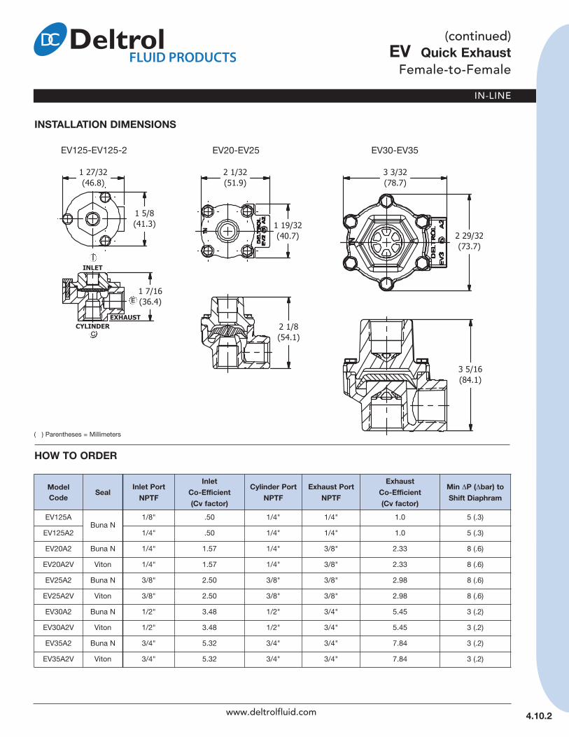
IN-LINE
4.10.2
(continued)eV Quick exhaust
Female-to-Female
HOW TO OrDer
( ) Parentheses = Millimeters
Model Code Seal Inlet Port
nPTF
InletCo-efficient(Cv factor)
Cylinder Port nPTF
exhaust Port nPTF
exhaustCo-efficient (Cv factor)
Min ΔP (Δbar) to Shift Diaphram
EV125ABuna N
1/8" .50 1/4" 1/4" 1.0 5 (.3)
EV125A2 1/4" .50 1/4" 1/4" 1.0 5 (.3)
EV20A2 Buna N 1/4" 1.57 1/4" 3/8" 2.33 8 (.6)
EV20A2V Viton 1/4" 1.57 1/4" 3/8" 2.33 8 (.6)
EV25A2 Buna N 3/8" 2.50 3/8" 3/8" 2.98 8 (.6)
EV25A2V Viton 3/8" 2.50 3/8" 3/8" 2.98 8 (.6)
EV30A2 Buna N 1/2" 3.48 1/2" 3/4" 5.45 3 (.2)
EV30A2V Viton 1/2" 3.48 1/2" 3/4" 5.45 3 (.2)
EV35A2 Buna N 3/4" 5.32 3/4" 3/4" 7.84 3 (.2)
EV35A2V Viton 3/4" 5.32 3/4" 3/4" 7.84 3 (.2)
www.deltrolfluid.com
InSTALLATIOn DIMenSIOnS
EV20-EV25 EV30-EV35EV125-EV125-2
E
I
C

IN-LINE
SL Slide ValveMale-to-Female
18 01/14
DeSCrIPTIOnThe Pneu-Trol slide valve is a manually operated, two-position,three-way valve for pneumatic applications. Ideal for applicationssuch as gauges, air tools, air clamps, and single acting cylinders.
• Two-Position, Three-Way manually operated valve• For pneumatic applications only up to 250 psi (17 bar)• Brass Sleeves assures ease of control and positive action
SPeCIFICATIOnSMaximum Operating Pressure (non-Shock Service)Carbon Steel: 250 psi (17 bar)
Operating Temperature range (O-ring)Buna N: -30° to +250° F (-34° to +120° C)
Flow ratingCo-Efficient (Cv Factor) = .98 to 3.26
ThreadsNPTF
MaterialsBody: SteelSleeve: BrassO-Rings: Buna NRetaining Ring: Steel
HOW TO OrDer
Size nPTF Thread Co-efficient(Cv Factor)
1/8" SL10 .98
1/4" SL20 1.53
3/8" SL25 1.78
1/2" SL30 3.26
InSTALLATIOn DIMenSIOnS
( ) Parentheses = Millimeters
PipeSize A Diameter B
1/8" 7/8 (22.2) 2-1/2 (63.5)
1/4" 1-1/8 (28.6) 2-3/4 (69.9)
3/8" 1-1/8 (28.6) 2-13/16 (71.5)
1/2" 1-1/2 (38.1) 3-3/4 (95.3)
4.20.1 www.deltrolfluid.com
21
V

IN-LINE
GI21S Gauge IsolatorFemale-to-Female
13 01/14
4.25.1www.deltrolfluid.com
( ) Parentheses = Millimeters
HOW TO OrDerInSTALLATIOn DIMenSIOnS
DeSCrIPTIOnThe Pneu-Trol gauge isolator valve is designed to prevent surge damage toa gauge in all types of hydraulic circuits. The gauge isolator valve also actsas a snubber to prevent damage to other hydraulic components –hydraulic chatter, pulsation and fluid hammer can cause costly down timeof equipment.
Simple to operate – just push to read. Depressing the knob allows fluid toflow around the spool to the gauge. When the spring-loaded knob isreleased the spool is automatically returned to the closed position, allowingthe fluid to drain from the gauge out the tank port.
• For hydraulic applications only• Push to operate – spring return• Legible instructions knob – “Push To read”• Panel or bracket mountable
SPeCIFICATIOnS
Maximum Operating Pressure(non-Shock Service) Carbon Steel: 3,000 psi (207 bar)
Operating Temperature range-30° to +250° F (-54° to +120° C)
Internal Leakage Pressure PortTo Tank Port20 cc/min. max at 2,500 psi (172 bar)
ThreadsNPTF 1/4"
Stroke1/4" (6.4)
Size nPTF ThreadSteel Orifice
1/4"GI21S .020"
GI21S-C5 .062"
Gauge Port Orifice.020" (.51 mm) and .062" (1.57 mm)
Panel Mounting Hole Size31/32" (24.6)
MaterialsBody, Plugs, Retainers: SteelSpool: Hardened SteelSpring: Music WireO-Rings: Buna-NBack-Up Washers: TeflonSet Screw: SteelKnob: Blue Anodized AluminumPanel Mount Nut: Nickel Plated Brass
P
G
T

www.deltrolfluid.com 18 01/14
4.30.1
AB20S Air Bleed ValveFemale-to-Female
DeSCrIPTIOnThe Pneu-Trol air bleed valve is used to remove trapped air from ahydraulic system, allowing system pump to prime itself. The valvewill pass air or a small amount of oil with pump pressure below50 psi (3.4 bar). Trapped air in the system is bled off back to thereservoir until a solid stream of hydraulic fluid at +50 psi (3.4 bar)closes the valve. This is automatic during every system start-up.The valve should be installed at the high point of the hydraulicsystem using a tee connection.
• For hydraulic applications only• removes air trapped in hydraulic system
SPeCIFICATIOnS
Maximum Operating Pressure(non-Shock Service)Carbon Steel: 5,000 psi (345 bar)
Minimum Seating Pressure50 psi (3.4 bar)
Operating Temperature range (O-ring)Buna N: -30° to +400° F (-34° to +204° C)
ThreadsNPTF 1/4"
Orifice Diameter.089 (2.3)
MaterialsBody: SteelSpring: Stainless Steel 302Ball: Stainless Steel 440Washer: SteelRetainer Ring: Steel
( ) Parentheses = Millimeters
HOW TO OrDer
Size nPTF ThreadSteel
1/4" AB20S
InSTALLATIOn DIMenSIOnS
21
IN-LINE

IN-LINE
07/13
5.01.1www.deltrolfluid.com
Flow CurvesEN**, ENB**, ENBP**, ENM**
EF**, EFB**, EFBP**, EFM**
FLOW CurVeS
FLOW rATInGPreSSure DrOP VS. nuMBer TurnS OPen(Controlled Flow)Test Medium: 150 SSU Oil @ 140°F
FOr LIQuID Cv √ (P1 – P2)
Flow in GPM =
√ Gf
FOr GAS Q(scfh) = 42.2 Cv √ (P1 – P2)(P1 + P2)
√ Gf
When P2 is less than P12
the Expression √ (P1 – P2) (P1 + P2)
becomes 0.87P1.
Cv = flow coefficientQ = std. cubic feet per hour at 14.7 PSIA and 60°FP1 = inlet pressure (PSIA)P2 = outlet pressure (PSIA)Gf = specific gravity of media at operating temperature (air = 1.0)
Pressures are absolute pressures.
FLOW COnTrOLCO-eFFICIenT(Cv FACTOR)(Fully Open-Controlled)
1/8" .2751/4" .5253/8" .7561/2" .9273/4" 1.4301" 8.000
neeDLeCO-eFFICIenT(Cv FACTOR)(Fully Open-Controlled)
1/8" .2541/4" .5063/8" .9171/2" 1.2003/4" 1.8401" 9.600
CHeCk FLOWCO-eFFICIenT(Cv FACTOR)(Return Flow)
1/8" .7501/4" 1.4703/8" 3.3001/2" 3.6003/4" 5.4101" 9.600
How to AdjustFrom the closed position, open the valve by turning metal knobcounter-clockwise until the desired flow volume is obtained.
The colored band on the stem and the numerical readout indicate to what extent the valve is opened or closed. Eachcolor on the color band represents one full turn.
Find the scribe mark on the upper surface of the valve body.The number on the knob in proximity to the scribe mark willindicate 10ths of a turn the valve is opened.
Record the information for future reference.
note: Curves shown are graphical representations of Flow andNeedle Valve meterability. Do not use as engineering data.
en** neeDLe VALVe See Page 2.10.1
eF** FLOW COnTrOL See Page 2.25.1
TECHNICALDATA

www.deltrolfluid.com
notes

MINIATURE
Miniature SeriesFlow Control, Needle Valves &
Ball Valves
07/13
6.00.0
LFC, LFV, AnD LnB SerIeSMiniature Flow Controls and Needle Valves
The LFC and LFV Series Flow Controls are designed to allow controlled flow either into or out of the component.
The LNB Series Needle Valve provides a wide range of adjustment in both directions.
Pressure range: 15 – 145 PSITemperature range: 0° – 160°FMedia: Air/WaterSizes: Inch and Metric
1 Body Nickel Plated Brass2 Banjo Body Nickel Plated Brass3 Shaft Clip Stainless Steel4 Adjusting Needle Nickel Plated Brass5 Adjusting Knob Nickel Plated Brass6 Locking Nut Nickel Plated Brass7 O-Ring NBR-708 O-Ring NBR-709 Lip Seal NBR-7010 Thread Seal NBR-7011 Seal Support NBR-70
Series LFC (C)Controlled Flow Out
Series LFV (V)Controlled Flow In
Series LnB (B)Needle Valve–Bi-Directional Flow
1
2
3
4
5 6
7
8
9
10
11
1
2
3
4
5
6
7
8
9
10
The Swift-Fit Universal Thread
System allows a wide range of
application compatibility.
For example, the 1/8" Swift-Fit
Thread is compatible
with 1/8" NPT, 1/8" NPTF,
1/8" BSPT, 1/8" BSPP,
RC 1/8", and G 1/8" Threads.
The fittings are designed with a
lip type seal for exceptional
sealing in both pressure and
vacuum applications. The
thread system will also allow
sealing on inclined, concave,
and convex surfaces.
SWIFT-FITuniversal Thread System
NPTBSPTRC
NPTFBSPP
G
MBV SerIeSMiniature Ball Valves
The Mini Ball Valve body is made of chrome plated brass for corrosion resistance andlong life. The valve is designed with a captured stem for blow out proof operation anda teflon seal to accommodate a variety of fluids and gases.
Pressure range: 0 – 250 PSIPipe Sizes: 1/8", 1/4", 3/8", 1/2" NPTFTemperature range: 0° – 160°FMedia: Air, Water, Gas
1 Body Chrome Plated Brass2 Ball Seats Teflon3 Stem Seal NBR-704 Stem Chrome Plated Brass5 Handle Glass Filled Nylon6 Handle Plate Nylon7 Handle Screw Plated Steel8 Ball Retainer Seal NBR-709 Ball Retainer Chrome Plated Brass10 Ball Chrome Plated Brass
www.deltrolfluid.com
Miniature Series
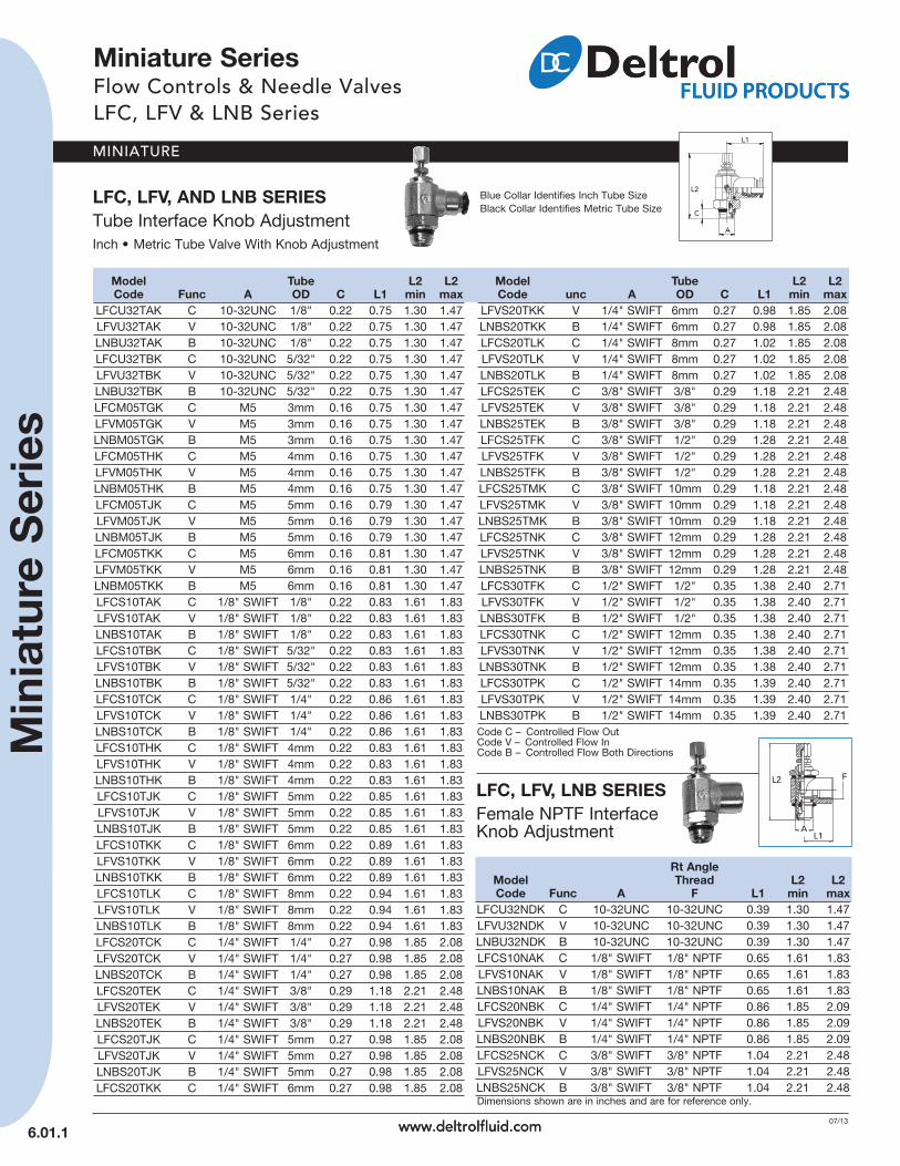
MINIATURE
Miniature SeriesFlow Controls & Needle ValvesLFC, LFV & LNB Series
07/13
6.01.1
LFC, LFV, AnD LnB SerIeSTube Interface Knob AdjustmentInch • Metric Tube Valve With Knob Adjustment
Model Tube L2 L2Code Func A OD C L1 min max
LFCU32TAK C 10-32UNC 1/8" 0.22 0.75 1.30 1.47LFVU32TAK V 10-32UNC 1/8" 0.22 0.75 1.30 1.47LNBU32TAK B 10-32UNC 1/8" 0.22 0.75 1.30 1.47LFCU32TBK C 10-32UNC 5/32" 0.22 0.75 1.30 1.47LFVU32TBK V 10-32UNC 5/32" 0.22 0.75 1.30 1.47LNBU32TBK B 10-32UNC 5/32" 0.22 0.75 1.30 1.47LFCM05TGK C M5 3mm 0.16 0.75 1.30 1.47LFVM05TGK V M5 3mm 0.16 0.75 1.30 1.47LNBM05TGK B M5 3mm 0.16 0.75 1.30 1.47LFCM05THK C M5 4mm 0.16 0.75 1.30 1.47LFVM05THK V M5 4mm 0.16 0.75 1.30 1.47LNBM05THK B M5 4mm 0.16 0.75 1.30 1.47LFCM05TJK C M5 5mm 0.16 0.79 1.30 1.47LFVM05TJK V M5 5mm 0.16 0.79 1.30 1.47LNBM05TJK B M5 5mm 0.16 0.79 1.30 1.47LFCM05TKK C M5 6mm 0.16 0.81 1.30 1.47LFVM05TKK V M5 6mm 0.16 0.81 1.30 1.47LNBM05TKK B M5 6mm 0.16 0.81 1.30 1.47LFCS10TAK C 1/8" SWIFT 1/8" 0.22 0.83 1.61 1.83LFVS10TAK V 1/8" SWIFT 1/8" 0.22 0.83 1.61 1.83LNBS10TAK B 1/8" SWIFT 1/8" 0.22 0.83 1.61 1.83LFCS10TBK C 1/8" SWIFT 5/32" 0.22 0.83 1.61 1.83LFVS10TBK V 1/8" SWIFT 5/32" 0.22 0.83 1.61 1.83LNBS10TBK B 1/8" SWIFT 5/32" 0.22 0.83 1.61 1.83LFCS10TCK C 1/8" SWIFT 1/4" 0.22 0.86 1.61 1.83LFVS10TCK V 1/8" SWIFT 1/4" 0.22 0.86 1.61 1.83LNBS10TCK B 1/8" SWIFT 1/4" 0.22 0.86 1.61 1.83LFCS10THK C 1/8" SWIFT 4mm 0.22 0.83 1.61 1.83LFVS10THK V 1/8" SWIFT 4mm 0.22 0.83 1.61 1.83LNBS10THK B 1/8" SWIFT 4mm 0.22 0.83 1.61 1.83LFCS10TJK C 1/8" SWIFT 5mm 0.22 0.85 1.61 1.83LFVS10TJK V 1/8" SWIFT 5mm 0.22 0.85 1.61 1.83LNBS10TJK B 1/8" SWIFT 5mm 0.22 0.85 1.61 1.83LFCS10TKK C 1/8" SWIFT 6mm 0.22 0.89 1.61 1.83LFVS10TKK V 1/8" SWIFT 6mm 0.22 0.89 1.61 1.83LNBS10TKK B 1/8" SWIFT 6mm 0.22 0.89 1.61 1.83LFCS10TLK C 1/8" SWIFT 8mm 0.22 0.94 1.61 1.83LFVS10TLK V 1/8" SWIFT 8mm 0.22 0.94 1.61 1.83LNBS10TLK B 1/8" SWIFT 8mm 0.22 0.94 1.61 1.83LFCS20TCK C 1/4" SWIFT 1/4" 0.27 0.98 1.85 2.08LFVS20TCK V 1/4" SWIFT 1/4" 0.27 0.98 1.85 2.08LNBS20TCK B 1/4" SWIFT 1/4" 0.27 0.98 1.85 2.08LFCS20TEK C 1/4" SWIFT 3/8" 0.29 1.18 2.21 2.48LFVS20TEK V 1/4" SWIFT 3/8" 0.29 1.18 2.21 2.48LNBS20TEK B 1/4" SWIFT 3/8" 0.29 1.18 2.21 2.48LFCS20TJK C 1/4" SWIFT 5mm 0.27 0.98 1.85 2.08LFVS20TJK V 1/4" SWIFT 5mm 0.27 0.98 1.85 2.08LNBS20TJK B 1/4" SWIFT 5mm 0.27 0.98 1.85 2.08LFCS20TKK C 1/4" SWIFT 6mm 0.27 0.98 1.85 2.08
Model Tube L2 L2Code unc A OD C L1 min max
LFVS20TKK V 1/4" SWIFT 6mm 0.27 0.98 1.85 2.08LNBS20TKK B 1/4" SWIFT 6mm 0.27 0.98 1.85 2.08LFCS20TLK C 1/4" SWIFT 8mm 0.27 1.02 1.85 2.08LFVS20TLK V 1/4" SWIFT 8mm 0.27 1.02 1.85 2.08LNBS20TLK B 1/4" SWIFT 8mm 0.27 1.02 1.85 2.08LFCS25TEK C 3/8" SWIFT 3/8" 0.29 1.18 2.21 2.48LFVS25TEK V 3/8" SWIFT 3/8" 0.29 1.18 2.21 2.48LNBS25TEK B 3/8" SWIFT 3/8" 0.29 1.18 2.21 2.48LFCS25TFK C 3/8" SWIFT 1/2" 0.29 1.28 2.21 2.48LFVS25TFK V 3/8" SWIFT 1/2" 0.29 1.28 2.21 2.48LNBS25TFK B 3/8" SWIFT 1/2" 0.29 1.28 2.21 2.48LFCS25TMK C 3/8" SWIFT 10mm 0.29 1.18 2.21 2.48LFVS25TMK V 3/8" SWIFT 10mm 0.29 1.18 2.21 2.48LNBS25TMK B 3/8" SWIFT 10mm 0.29 1.18 2.21 2.48LFCS25TNK C 3/8" SWIFT 12mm 0.29 1.28 2.21 2.48LFVS25TNK V 3/8" SWIFT 12mm 0.29 1.28 2.21 2.48LNBS25TNK B 3/8" SWIFT 12mm 0.29 1.28 2.21 2.48LFCS30TFK C 1/2" SWIFT 1/2" 0.35 1.38 2.40 2.71LFVS30TFK V 1/2" SWIFT 1/2" 0.35 1.38 2.40 2.71LNBS30TFK B 1/2" SWIFT 1/2" 0.35 1.38 2.40 2.71LFCS30TNK C 1/2" SWIFT 12mm 0.35 1.38 2.40 2.71LFVS30TNK V 1/2" SWIFT 12mm 0.35 1.38 2.40 2.71LNBS30TNK B 1/2" SWIFT 12mm 0.35 1.38 2.40 2.71LFCS30TPK C 1/2" SWIFT 14mm 0.35 1.39 2.40 2.71LFVS30TPK V 1/2" SWIFT 14mm 0.35 1.39 2.40 2.71LNBS30TPK B 1/2" SWIFT 14mm 0.35 1.39 2.40 2.71
Blue Collar Identifies Inch Tube SizeBlack Collar Identifies Metric Tube Size
Code C – Controlled Flow OutCode V – Controlled Flow InCode B – Controlled Flow Both Directions
LFC, LFV, LnB SerIeSFemale NPTF Interface Knob Adjustment
rt AngleModel Thread L2 L2Code Func A F L1 min max
LFCU32NDK C 10-32UNC 10-32UNC 0.39 1.30 1.47LFVU32NDK V 10-32UNC 10-32UNC 0.39 1.30 1.47LNBU32NDK B 10-32UNC 10-32UNC 0.39 1.30 1.47LFCS10NAK C 1/8" SWIFT 1/8" NPTF 0.65 1.61 1.83LFVS10NAK V 1/8" SWIFT 1/8" NPTF 0.65 1.61 1.83LNBS10NAK B 1/8" SWIFT 1/8" NPTF 0.65 1.61 1.83LFCS20NBK C 1/4" SWIFT 1/4" NPTF 0.86 1.85 2.09LFVS20NBK V 1/4" SWIFT 1/4" NPTF 0.86 1.85 2.09LNBS20NBK B 1/4" SWIFT 1/4" NPTF 0.86 1.85 2.09LFCS25NCK C 3/8" SWIFT 3/8" NPTF 1.04 2.21 2.48LFVS25NCK V 3/8" SWIFT 3/8" NPTF 1.04 2.21 2.48LNBS25NCK B 3/8" SWIFT 3/8" NPTF 1.04 2.21 2.48Dimensions shown are in inches and are for reference only.
www.deltrolfluid.comwww.deltrolfluid.com
Min
iatu
re S
erie
s

MINIATURE
6.01.2
(continued)Flow Controls & Needle Valves
LFC, LFV & LNB Series
LFC, LFV, AnD LnB SerIeSTube Interface Screw AdjustmentInch • Metric Tube Valve With Knob Adjustment
Code C – Controlled Flow OutCode V – Controlled Flow InCode B – Controlled Flow Both Directions
LFC, LFV, LnB SerIeSFemale NPTF Interface Screw Adjustment
Model TubeCode Func A OD C L1 L2
LFCU32TAS C 10-32UNC 1/8" 0.16 0.75 0.95LFVU32TAS V 10-32UNC 1/8" 0.16 0.75 0.95LNBU32TAS B 10-32UNC 1/8" 0.16 0.75 0.95LFCU32TBS C 10-32UNC 5/32" 0.16 0.75 0.95LFVU32TBS V 10-32UNC 5/32" 0.16 0.75 0.95LNBU32TBS B 10-32UNC 5/32" 0.16 0.75 0.95LFCM05TGS C M5 3mm 0.16 0.75 0.95LFVM05TGS V M5 3mm 0.16 0.75 0.95LNBM05TGS B M5 3mm 0.16 0.75 0.95LFCM05THS C M5 4mm 0.16 0.75 0.95LFVM05THS V M5 4mm 0.16 0.75 0.95LNBM05THS B M5 4mm 0.16 0.75 0.95LFCM05TJS C M5 5mm 0.16 0.79 0.95LFVM05TJS V M5 5mm 0.16 0.79 0.95LNBM05TJS B M5 5mm 0.16 0.79 0.95LFCM05TKS C M5 6mm 0.16 0.81 0.95LFVM05TKS V M5 6mm 0.16 0.81 0.95LNBM05TKS B M5 6mm 0.16 0.81 0.95LFCS10TAS C 1/8" SWIFT 1/8" 0.22 0.83 1.18LFVS10TAS V 1/8" SWIFT 1/8" 0.22 0.83 1.18LNBS10TAS B 1/8" SWIFT 1/8" 0.22 0.83 1.18LFCS10TBS C 1/8" SWIFT 5/32" 0.22 0.83 1.18LFVS10TBS V 1/8" SWIFT 5/32" 0.22 0.83 1.18LNBS10TBS B 1/8" SWIFT 5/32" 0.22 0.83 1.18LFCS10TCS C 1/8" SWIFT 1/4" 0.22 0.87 1.18LFVS10TCS V 1/8" SWIFT 1/4" 0.22 0.87 1.18LNBS10TCS B 1/8" SWIFT 1/4" 0.22 0.87 1.18LFCS10THS C 1/8" SWIFT 4mm 0.22 0.83 1.18LFVS10THS V 1/8" SWIFT 4mm 0.22 0.83 1.18LNBS10THS B 1/8" SWIFT 4mm 0.22 0.83 1.18LFCS10TJS C 1/8" SWIFT 5mm 0.22 0.85 1.18LFVS10TJS V 1/8" SWIFT 5mm 0.22 0.85 1.18LNBS10TJS B 1/8" SWIFT 5mm 0.22 0.85 1.18LFCS10TKS C 1/8" SWIFT 6mm 0.22 0.89 1.18LFVS10TKS V 1/8" SWIFT 6mm 0.22 0.89 1.18LNBS10TKS B 1/8" SWIFT 6mm 0.22 0.89 1.18LFCS10TLS C 1/8" SWIFT 8mm 0.22 0.94 1.18LFVS10TLS V 1/8" SWIFT 8mm 0.22 0.94 1.18LNBS10TLS B 1/8" SWIFT 8mm 0.22 0.94 1.18LFCS20TCS C 1/4" SWIFT 1/4" 0.28 0.98 1.42LFVS20TCS V 1/4" SWIFT 1/4" 0.28 0.98 1.42LNBS20TCS B 1/4" SWIFT 1/4" 0.28 0.98 1.42LFCS20TES C 1/4" SWIFT 3/8" 0.29 1.18 1.61LFVS20TES V 1/4" SWIFT 3/8" 0.29 1.18 1.61LNBS20TES B 1/4" SWIFT 3/8" 0.29 1.18 1.61LFCS20TJS C 1/4" SWIFT 5mm 0.28 0.96 1.40LFVS20TJS V 1/4" SWIFT 5mm 0.28 0.96 1.40LNBS20TJS B 1/4" SWIFT 5mm 0.28 0.96 1.40LFCS20TKS C 1/4" SWIFT 6mm 0.28 0.98 1.40
Model TubeCode Func A OD C L1 L2
LFVS20TKS V 1/4" SWIFT 6mm 0.28 0.98 1.40LNBS20TKS B 1/4" SWIFT 6mm 0.28 0.98 1.40LFCS20TLS C 1/4" SWIFT 8mm 0.28 1.02 1.40LFVS20TLS V 1/4" SWIFT 8mm 0.28 1.02 1.40LNBS20TLS B 1/4" SWIFT 8mm 0.28 1.02 1.40LFCS25TES C 3/8" SWIFT 3/8" 0.29 1.18 1.61LFVS25TES V 3/8" SWIFT 3/8" 0.29 1.18 1.61LNBS25TES B 3/8" SWIFT 3/8" 0.29 1.18 1.61LFCS25TFS C 3/8" SWIFT 1/2" 0.29 1.28 1.61LFVS25TFS V 3/8" SWIFT 1/2" 0.29 1.28 1.61LNBS25TFS B 3/8" SWIFT 1/2" 0.29 1.28 1.61LFCS25TMS C 3/8" SWIFT 10mm 0.29 1.20 1.61LFVS25TMS V 3/8" SWIFT 10mm 0.29 1.20 1.61LNBS25TMS B 3/8" SWIFT 10mm 0.29 1.20 1.61LFCS25TNS C 3/8" SWIFT 12mm 0.29 1.28 1.61LFVS25TNS V 3/8" SWIFT 12mm 0.29 1.28 1.61LNBS25TNS B 3/8" SWIFT 12mm 0.29 1.28 1.61LFCS30TFS C 1/2" SWIFT 1/2" 0.35 1.38 1.85LFVS30TFS V 1/2" SWIFT 1/2" 0.35 1.38 1.85LNBS30TFS B 1/2" SWIFT 1/2" 0.35 1.38 1.85LFCS30TNS C 1/2" SWIFT 12mm 0.35 1.38 1.85LFVS30TNS V 1/2" SWIFT 12mm 0.35 1.38 1.85LNBS30TNS B 1/2" SWIFT 12mm 0.35 1.38 1.85LFCS30TPS C 1/2" SWIFT 14mm 0.35 1.40 1.85LFVS30TPS V 1/2" SWIFT 14mm 0.35 1.40 1.85LNBS30TPS B 1/2" SWIFT 14mm 0.35 1.40 1.85
Blue Collar Identifies Inch Tube SizeBlack Collar Identifies Metric Tube Size
rt AngleModel Thread Code Func A F L1 L2
LFCU32NDS C 10-32UNC 10-32UNC 0.39 0.95
LFVU32NDS V 10-32UNC 10-32UNC 0.39 0.95
LNBU32NDS B 10-32UNC 10-32UNC 0.39 0.95
LFCS10NAS C 1/8" SWIFT 1/8" NPTF 0.65 1.18
LFVS10NAS V 1/8" SWIFT 1/8" NPTF 0.65 1.18
LNBS10NAS B 1/8" SWIFT 1/8" NPTF 0.65 1.18
LFCS20NBS C 1/4" SWIFT 1/4" NPTF 0.86 1.42
LFVS20NBS V 1/4" SWIFT 1/4" NPTF 0.86 1.42
LNBS20NBS B 1/4" SWIFT 1/4" NPTF 0.86 1.42
LFCS25NCS C 3/8" SWIFT 3/8" NPTF 1.04 1.61
LFVS25NCS V 3/8" SWIFT 3/8" NPTF 1.04 1.61
LNBS25NCS B 3/8" SWIFT 3/8" NPTF 1.04 1.61
www.deltrolfluid.comwww.deltrolfluid.com
Miniature Series

I N- LI NEMINIATURE
Miniature SeriesBall ValvesMBV Series
07/13
6.02.1
MBV SerIeS
Miniature Ball Valve Female nPTF Model A BCode nPTF nPTF Orifice L C H
MBVFF1010 1/8" 1/8" 0.22 1.48 0.75 0.83MBVFF2020 1/4" 1/4" 0.22 1.81 0.75 0.83MBVFF2525 3/8" 3/8" 0.32 1.91 0.75 0.87MBVFF3030 1/2" 1/2" 0.39 2.44 1.02 1.20
Miniature Ball Valve Male nPTF, Female nPTF Model A BCode nPTF nPTF Orifice F L C H
MBVMF1010 1/8" 1/8" 0.22 0.55 1.45 0.75 0.83MBVMF2020 1/4" 1/4" 0.22 0.55 1.81 0.75 0.83MBVMF2525 3/8" 3/8" 0.32 0.71 1.87 0.75 0.87MBVMF3030 1/2" 1/2" 0.39 0.87 2.37 1.02 1.20
Miniature Ball Valve Tube, Tube Model Tube TubeCode OD OD L C H
MBVT2TATA 1/8" 1/8" 1.67 0.75 0.83MBVT2TCTC 1/4" 1/4" 1.83 0.75 0.83MBVT2TETE 3/8" 3/8" 2.38 0.75 0.87
Miniature Ball Valve Tube, Male nPTFModel A TubeCode nPTF OD F L C H
MBVMT10TB 1/8" 5/32" 0.33 1.37 0.74 0.82MBVMT10TC 1/8" 1/4" 0.33 1.37 0.74 0.82MBVMT20TC 1/4" 1/4" 0.48 1.50 0.74 0.82MBVMT25TE 3/8" 3/8" 0.51 1.75 0.74 0.86
Miniature Ball Valve Female nPTF, Closed Center
Miniature Ball Valve Female nPTF, Open Center
Model A B CCode nPTF nPTF nPTF Orifice L G H1 H2 S max
MBVF3C10 1/8" 1/8" 1/8" 0.22 1.48 0.75 1.32 0.65 0.17MBVF3C20 1/4" 1/4" 1/4" 0.22 1.81 0.75 1.32 0.83 0.17MBVF3C25 3/8" 3/8" 3/8" 0.28 1.91 0.75 1.38 0.87 0.17
Miniature Ball Valve right Angle Female nPTF, Female nPTF
Model A B CCode nPTF nPTF nPTF Orifice L G H1 H2 S max
MBVF3P10 1/8" 1/8" 1/8" 0.22 1.48 0.75 1.32 0.65 0.17MBVF3P20 1/4" 1/4" 1/4" 0.22 1.81 0.75 1.32 0.83 0.17MBVF3P25 3/8" 3/8" 3/8" 0.28 1.91 0.75 1.38 0.87 0.17
Model A BCode nPTF nPTF Orifice L G H1 H2 S max
MBVFRA10 1/8" 1/8" 0.22 1.20 0.75 1.32 0.65 0.17MBVFRA20 1/4" 1/4" 0.22 1.36 0.75 1.32 0.83 0.17MBVFRA25 3/8" 3/8" 0.28 1.54 0.75 1.38 0.87 0.17
www.deltrolfluid.com
Min
iatu
re S
erie
s
02/14
7.99.1www.deltrolfluid.com
Warranty andDisclaimer
WArrAnTyDeltrol Fluid Products Division/Deltrol Corp. warrants each product manufactured by it to be free from defects in material and workmanship under normal use and service appearing within one (1) year. The obligation of Deltrol Fluid Products Division/Deltrol Corp. and the right of the purchaser under this warranty are limited to repair or replacement (at the option of Deltrol Fluid Products Division/Deltrol Corp.) at the factory. The purchaser must give notice of any defect within one (1) year from the date of purchase and must return the product intact, at its expense. Deltrol Fluid Products Division/Deltrol Corp. will have no responsibility to repair or replace product which has been repaired or altered by anyone other than Deltrol Fluid Products Division/DeltrolCorp., or which has been subject to misuse, negligence, accident, incorrect connection, or improper installation.
This warranty is in lieu of any other warranties, express or implied; and seller specifically disclaims andimplied warranty or merchantability of fitness for any particular purpose.
DISCLAIMer OF OTHer LIABILITIeS
The liability of Deltrol Fluid Products Division/Deltrol Corp. with respect to products that it sells is limited to performance under the warranty set forth above.
Deltrol Fluid Products Division/Deltrol Corp. shall not be subject to and disclaims: (A) Any other obligations or liabilities arising out of breach of contract or of warranty, (B) Any obligations whatsoever arising from tort claims (including negligence and strict liability claims) or arising under other theories of law with respect to goods sold or any undertakings, acts or omissions relating thereto, and (C) All consequential, incidental, special and contingent damages whatsoever.
WArnInGThe products shown in this catalog were designed and developed for use in fluid power applications. Do not use the products in other applications without the express written approval of Deltrol Fluid Products Division/Deltrol Corp. Misuse of the products, including use in other applications, may causedeath, serious injury or property damage.
nOTICeDeltrol Fluid Products Division/Deltrol Corp. reserves the right to change designs and/or specifications withoutnotice. Although it has attempted to check the data, dimensions and tables in this catalog, Deltrol FluidProducts Division/Deltrol Corp. will have no responsibility for errors or omissions that it may contain.
3001 Grant Avenue | Bellwood, Illinois 60104PHONE 708. 547. 0500 | FAX 708. 547. 6881EMAIL [email protected]
www.de l t ro l f l u i d . c om© Copyright 2014 Deltrol Fluid Products03/14
Please visit us at www.de l t ro l f l u i d . c omfor information on these other Deltrol product lines:
• Hydraulic Integrated Circuit Manifolds
• Cartridge Valves & Integrated Circuit Manifolds
• Custom Solutions for Your Fluid Power and Fluid Control Demands
Or Contact Us and Request a Free Catalog
Please visit us at www.de l t ro l f l u i d . c omfor information on these other Deltrol product lines:
• Hydraulic Integrated Circuit Manifolds
• Cartridge Valves & Integrated Circuit Manifolds
• Custom Solutions for your Fluid Power and Fluid Control demands
Or Contact Us and Request a Free Catalog
Related Documents