INSTALLATION MANUAL ® ISO 9001 9105.BNT1 ISO 9001 IT-52587 ISO 14001 9191.BNT2 ISO 14001 IT-52588 FireClass ANALOGUE FIRE CONTROL PANEL

Welcome message from author
This document is posted to help you gain knowledge. Please leave a comment to let me know what you think about it! Share it to your friends and learn new things together.
Transcript
INSTALLATION MANUAL
®
ISO 90019105.BNT1
ISO 9001IT-52587
ISO 140019191.BNT2
ISO 14001IT-52588
FireClass
ANALOGUE FIRE CONTROL PANEL

This Fire Control panel can be programmed only using the Software FireClass500 Console release 1.0 or higher.
BENTEL SECURITYsrl shall not assume the responsibility for damage arising from improper application or use.
This Fire Control panel has been designed and manufactured to the highest standards of quality and performance.
Installation of this Control panel must be carried out strictly in accordance with the instructions described in this manual, and
in compliance with the local laws and bylaws in force
The FC510 and FC520 Fire Control panels comply with the essential requirements of standards EN54-2; EN54-4.
Recycling information
BENTEL SECURITY recommends that customers dispose of their
used equipments (panels, detectors, sirens, and other devices) in an
environmentally sound manner. Potential methods include reuse of
parts or whole products and recycling of products, components,
and/or materials.
For specific information see:
www.bentelsecurity.com/en/environment.htm
Waste Electrical and Electronic Equipment (WEEE) Di-
rective
In the European Union, this label indicates that this product
should NOT be disposed of with household waste. It should be depo-
sited at an appropriate facility to enable recovery and recycling.
For specific information see:
www.bentelsecurity.com/en/environment.htm
NOTE- The series FC500 Fire control panel can support several addressable devices (Detectors, Modules, Manual
call Points, etc). The present manual includes the instructions for their programming, but for further informations on
those devices and their accessories, please visits: www.bentelsecurity.com , logging in the Reserved Area, under
Installation Manuals.
BENTEL SECURITY srl reserves the right to change the technical specifications of these products without prior notice.
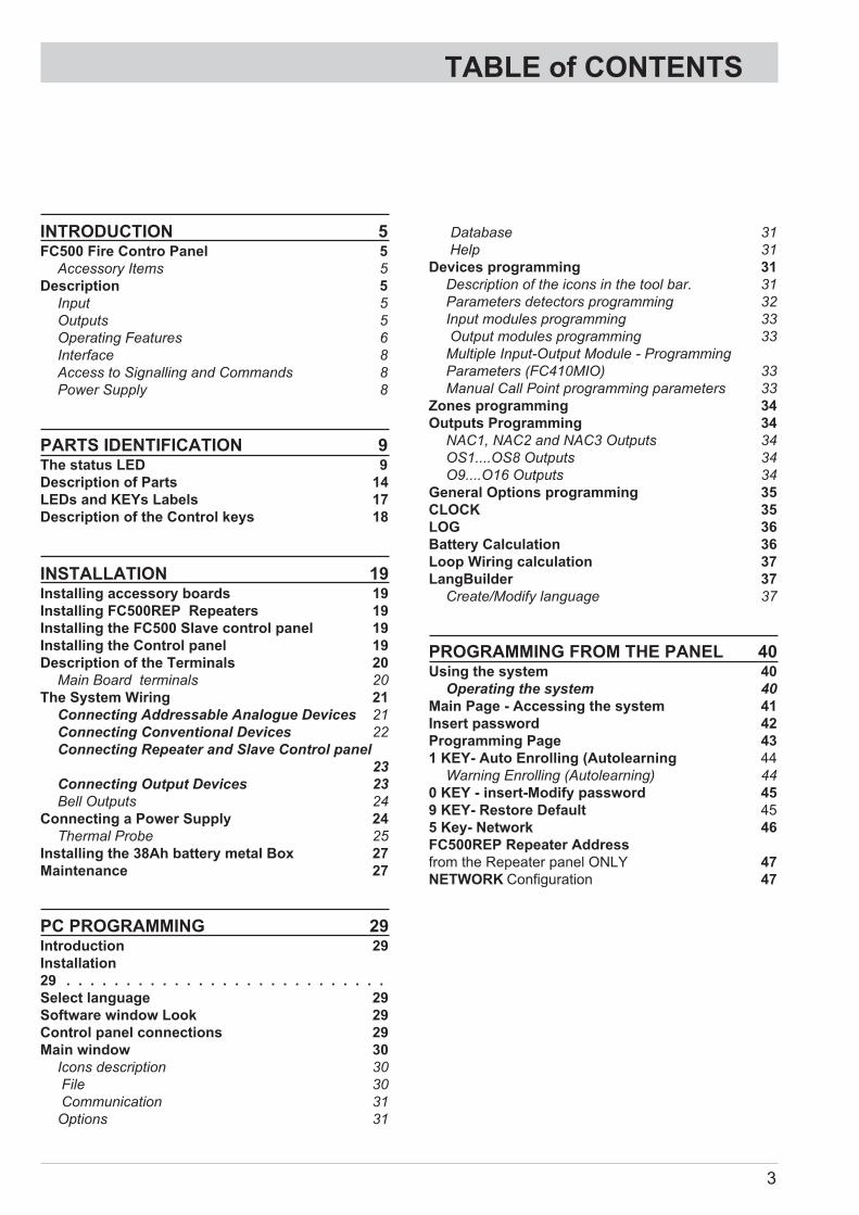
TABLE of CONTENTS
INTRODUCTION 5FC500 Fire Contro Panel 5
Accessory Items 5
Description 5
Input 5
Outputs 5
Operating Features 6
Interface 8
Access to Signalling and Commands 8
Power Supply 8
PARTS IDENTIFICATION 9The status LED 9
Description of Parts 14
LEDs and KEYs Labels 17
Description of the Control keys 18
INSTALLATION 19Installing accessory boards 19
Installing FC500REP Repeaters 19
Installing the FC500 Slave control panel 19
Installing the Control panel 19
Description of the Terminals 20
Main Board terminals 20
The System Wiring 21
Connecting Addressable Analogue Devices 21
Connecting Conventional Devices 22
Connecting Repeater and Slave Control panel
23
Connecting Output Devices 23
Bell Outputs 24
Connecting a Power Supply 24
Thermal Probe 25
Installing the 38Ah battery metal Box 27
Maintenance 27
PC PROGRAMMING 29Introduction 29
Installation
29 . . . . . . . . . . . . . . . . . . . . . . . . . . .
Select language 29
Software window Look 29
Control panel connections 29
Main window 30
Icons description 30
File 30
Communication 31
Options 31
Database 31
Help 31
Devices programming 31
Description of the icons in the tool bar. 31
Parameters detectors programming 32
Input modules programming 33
Output modules programming 33
Multiple Input-Output Module - Programming
Parameters (FC410MIO) 33
Manual Call Point programming parameters 33
Zones programming 34
Outputs Programming 34
NAC1, NAC2 and NAC3 Outputs 34
OS1....OS8 Outputs 34
O9....O16 Outputs 34
General Options programming 35
CLOCK 35
LOG 36
Battery Calculation 36
Loop Wiring calculation 37
LangBuilder 37
Create/Modify language 37
PROGRAMMING FROM THE PANEL 40Using the system 40
Operating the system 40
Main Page - Accessing the system 41
Insert password 42
Programming Page 43
1 KEY- Auto Enrolling (Autolearning 44
Warning Enrolling (Autolearning) 44
0 KEY - insert-Modify password 45
9 KEY- Restore Default 45
5 Key- Network 46
FC500REP Repeater Address
from the Repeater panel ONLY 47
NETWORK Configuration 47
3

QUICK START-UP PROCEDURE 48Detectors 48
Modules 48
Zones
49
Panel outputs 49
Conventional zone 49
Panel general option 49
QUICK GUIDE 50Technical features 50
Description of the terminals 50
4 Analogue Fire Panel FC500

INTRODUCTION
FC500 Fire Contro Panel
In this manual we will use the term FC500 control panel
to indicate the common features of Fire control panel.
Otherwise we will use the specific terms.
FC500 Fire control panel is avalaible in the following
models:
� FC510 - Analogue addressable Fire Control Panel
with one not expandable Loop and with Switching
Power supply 5,5 A;
� FC520 - Analogue addressable Fire Control Panel
with two not expandable Loops and with Switching
Power supply 5,5 A;
� The components of these Control panels operate
as intended when the external ambient conditions
comply with the requirements of class 3k5 of IEC
721-3-3:1978.
The Loops of FC500 control panel provide the follo-wing features:
� max 250 analogue devices.
� The conventional line of the FC500 contro Panel can
support up to 30 devices.
In any case, FC500 Fire control panel cannot sup-port more than 2000 devices (500 devices for every
couple of Loop) (up to 2000 m (Loop) with shielded
cable 2x2.5).
The FC500 control panel must be powered by BENTEL
BAQ140T24 (27,6 V - 5,5 A ) switching power supply.
Moreover all FC500 models provide housing for an LCD
module with 40 characters for line and 4 lines backlit,
which provides written information regarding the
system status and for programming the control panel.
� Accessory Items
FC500REP This Repeater panel is intended for con-
nection (via 4 wires) to FC500 Control panels. It provi-
des all the visual and audible warnings generated by
the Control panel and allows end-users to manage the
system from a remote location (up to 1000 m, with dou-
ble twist shielded cable).
The FC500 "Master" Control panels can support up to
(8) eight FC500REP Repeater panels.
A The Repeater FC500REP has NOT
IMQ-SECURITY SYSTEM certification.
FC500 Slave The FC500 "Master" Control panels can
support up to (7) seven FC500 Slave Control panels.
These Control Panels can be used to expand the
FC500 system, in modular way.
Software FireClass500 Console This user-friendly
software application (Windows) offers a quick and easy
way to program the Control panel and provides event
log functions.
Description
� Input
250 devices max every Loop
30 devices max on the conventional line
� Outputs
This section describes how the Control panel outputs
operate.
Supervised outputs The Control panel will be able to
detect and signal short-circuits and power supply inter-ruptions on this type of output.
Bypassable outputs The user will be able to disable
(by means of the respective key) this type of output.
Silenceable outputs The user will be able to stop (via
the Silence key) this type of output.
The outputs can be silenced for an indefinite period (du-ring Day Mode), or for the programmed Silence Time
(during Night Mode).
INTRODUCTION 5

� Operating Features
Warning The FC500 control panel can be program-med to provide WARNINGS or PREALARMS status be-fore ALARM status.
This status will be signalled by the WARNING display.
The panel will generate a warning when an input point
(detector) exceeds its warning threshold and there is
risk of an alarm.
-WARNING STATUS will be signalled by:
� a screen on LCD display
� the WARNING output points if the Pre-alarm option
is enabled;
Pre-alarm If a zone generates an alarm during Day
Mode, the Control panel will start the Pre-alarm Time.
This status will be signalled by:
� a slow intermittent beep;
� glowing on the Pre-al. LED;
� a screen on LCD display
� Activation of respective outputs , if the Pre-alarm
option is enabled;
� This Control panel will generate an Instant Alarm if
alarm conditions are detected during Night Mode
or if an alarm is triggered from a Callpoint.
During Pre-alarm status, you will be able to:
� activate an Evacuation Alarm by pressing and hol-ding the Evacuate Key (Access Level 1 — refer to
“Access to signalling and commands”),
� stop the Silenceable outputs and interrupt the
Pre-alarm Time by pressing the Silence key
(Access Level 2).
During Silence status (Silence LED glowing), it is pos-sible to use the Silence key to release the Silenceable
outputs, or use theReset key to restore standby status.
� If the Control panel is operating in Night Mode, the
Control panel will exit Silence status automatically
when the programmed Night mode Silence time
expires.
Alarm The Control panel will generate an alarm when
the Pre-Alarm Time expires. Alarm status will be signalled
by:
� a fast intermittent beep;
� glowing on the Alarm LEDs;
� a screen on LCD display;
� activation of the NAC FIRE output;
� activation of the FIRE outputs;
� activation of other programmed outputs
During Alarm status, PIN Code users (Access Level 2 —
refer to “Access to signalling and commands”) will be
able to:
� stop the Silenceable outputs by pressing the Silence key.
During Silence status (Silence LED glowing), it is pos-
sible to use the Silence key to release the Silenceable
outputs, and the Reset key to restore standby status.
� If the Control panel is in Night Mode (Day Mode
LED OFF), the Control panel will exit Silence sta-tus when the programmed Night mode Silence
time expires
Day/Night Mode The control panel can operate in
DAY or NIGHT Mode. See "PC PROGRAMMING"
chapter.
If the system is silenced during DAY Mode, SILENCE
status will be held until the system is unsilenced (i.e. un-
less new alarms). If the system is silenced during
NIGHT Mode, SILENCE status will be held until the
Night Mode Silence time expires.
On power up (at default) the system will set to DAY
Mode. During this operating mode, silenced alarms/fa-ults will not be unsilenced automatically until the Night
Mode Silence time expires.
Fault This Control panel can detect and signal the
Faults shown in the Table n.1:
Fault conditions will be signalled by:
� a slow intermittent beep (at 1 second intervals);
� glowing on the Fault LED and on relative Fault LED;
� a screen on LCD display;
� activation of the Fault output;
� activation of other programmed outputs;
� slow blinking on the Fault LED.
The Fault output and other outputs (if duly program-
med by your Installer) will restore to standby automati-
cally when fault conditions clear.
Under certain circumstances, fault conditions may clear
spontaneously, if this occurs, the event will be stored in
the memory until the Control panel Resets.
Stored Fault events will be signalled by:
� slow blinking on the Fault LED.
6 Analogue Fire Panel FC500

Silence This Control panel provides a Silence key
which can be used to restore the Silenceable outputs to
standby status.
Silence status will be signalled by:
� glowing on the Silence LED.
Silence status will be held until the Silence key is pres-sed again or, if the Control panel is operating in Night
Mode, until the programmed Night mode Silence time
expires, or until a new Alarm condition is detected.
� Only when the control panel is at Level 2 or at Le-
vel 3 can SILENCE the Silenceable outputs.
INTRODUCTION 7
Switching 1 Switching 1 Fault
Switching 2 Switching 2 Fault
Mains faultThe Control panel is NOT
powered from the Mains
BatteryThe Control panel batteries
charger not working properly
Low batteryThe Control panel batteries are
empty
Earth Leakage to Earth
24A Output 24A Output is shorted
24R Output 24R Output is shorted
Conv. zone openConventional zone (LC terminal )
open
Conv. zone shortConventional zone (LC terminal)
is shorted
Flash writing Flash writing error
Flash erasing LOG erasing error
Main controller Main controller fault
Firmware main contr. Checksun fault
Prog.data main contData programming Checksun
fault
Firmware Display Display Checksun fault
Loop CommunicationCommunication Loop fault
controller
Loop return open Loop negative signal open
Loop signal open Loop positive signal open
Loop local short Local short on Loop controller
Loop right short Right side Loop short
Loop left short Left side Loop short
Non answer Loop device does'nt answer
Dirty level(Smoke detector ONLY) the dirty
threshold has been exceeded
Short circuit Short circuit on Input module
Open circuit Open circuit on Input module
Power supply Main fault
Wrong value A Loop device has a wrong value
Stuck outputAn Output module relais is not
switched
Same addressLoop several devices have the
same address
Display communic.Communication fault on Display
controller
LOG Full LOG fault
LOG not valid LOG contents not valid
OS1 OpenOS1 terminal (Supervised output)
open
OS2 Open "
OS3 Open "
OS4 open "
OS5 open "
OS6 open "
OS7 open "
OS8 open "
Table 1 Faults table (Continued..)
OS1 short OS1 terminal is shorted
OS2 short "
OS3 short "
OS4 short "
OS5 short "
OS6 short "
OS7 short "
OS8 short "
TRANSISTOR OS1 OS1 Transistor fault
TRANSISTOR OS2 "
TRANSISTOR OS3 "
TRANSISTOR OS4 "
TRANSISTOR OS5 "
TRANSISTOR OS6 "
TRANSISTOR OS7 "
TRANSISTOR OS8 "
NAC FIRE short NAC Fire terminal is shorted
NAC 1 short "
NAC 2 short "
NAC 3 short "
NAC FIRE open NAC FIRE terminal is open
NAC 1open NAC1 terminal is open
NAC 2open "
NAC 3open "
Transistor NAC FIRE NAC FIRE transistor fault
Transistor NAC 1 NAC 1 transistor fault
Transistor NAC 2 "
Transistor NAC 3 "
Table 1 Faults Table

Disabled This Control panel can disable:
the devices on the Loop (input and Output devices),
the bell outputs, the software zones;
the network devices (Repeaters or Slave control pa-nels).
DISABLED zones cannot generate alarms or warnings
of any kind, and DISABLED outputs cannot be activa-ted.
Disabled status will be signalled by:
� glowing on the Disabled LED;
� Only when the control panel is at Level 2 or at Le-vel 3 can DISABLE zones and/or outputs.
Reset Resetting the Control panel will restore the out-puts to standby status, clear the memory, and interrupt
the power supply to terminals 24R.
� Only when the control panel is at Level 2 or at Le-vel 3 can Reset the system.
� Interface
Visual Signalling The system status will be signalled
on the Control panel LEDs as follows:
GREEN indicates normal operating conditions;
AMBER indicates specific operating modes (for exam-ple Day or Night mode), and/or Fault conditions;
RED indicates Alarm conditions.
Memory The Control panel will signal Fault events
(FAULT LED blinking) until the system Resets, even if
the event clears in the meantime.
Audible Signalling The Buzzer will signal the Control
panel status as follows:
Test LAMP-BUZZ-TEST key will allow ALL users to test
the Control panel Buzzer and LEDs.
� Access to Signalling and Commands
There are 4 access levels, in compliance with the Fire
Safety Regulations in force.
Access Level1 (L1) Viewing: ALL persons can view
the Control panel status (No password requested).
Access Level 2 (L2) Operating the system (PIN Code
entered): PIN Code Users can operate the system.
(User level)
Access Level 3 (L3) Programming and Opening the
Control panel (PIN Code entered): ONLY Qualified
persons with authorization are allowed to open the
Control panel door (requires removal of the screws) for
maintenance purposes or replace batteries. (Installer
Level).
Access Level 4 Repairing or replacing the PCB:
ONLY the Manufacturer should be allowed to repair or
replace the PCB, (requires removal of the screws).
� Power Supply
The power supply system of the FC500 Control panels
complies with EN54-4.
All models are powered by the Mains (230 V, 50 Hz):
� the FC510 model has Switching Power Supply which
supplies up to 5.5 A at 27.6 V;
� the FC520 model has Switching Power Supply which
supplies up to 5.5 A at 27.6 V;
All models can house two 12 V batteries which, when
connected in series, will supply 24 V to the Control pa-nel and peripherals in the event of black-out, and will
also provide any pickup currents which exceed the ma-ximum current supplied by the Switching Power Supply.
The FC510 and FC520 model can house two 12V 17 Ah
batteries (YUASA NP 17-12 FR model or similar — flame
class UL94-V2 or higher).
� If necessary, (Full configured Loop or for particular
requirements of the system) FC510 or FC520 con-trol panel model can be connected to two 12V
38 Ah batteries in an external metal box (see Figu-re 14).
This Control panel can detect, signal and store in memory
the following power faults: shorted 24V or 24R outputs;
Low battery, Battery fault or Battery disconnected (Low
Battery LED and No Battery LED), Ground fault (Earth
LED) and Mains failure (Mains LED).
� The “No Battery or Low Battery” fault may be si-gnalled with a delay up to 1 minute. The “Mains”
(Amber) fault will be signalled when the program-med delay expires.
8 Analogue Fire Panel FC500
Status Sound Pause Description
Warning 2 s 2 s Slow Intermittent Beep
Prealarm 0,5 s 0,5 s Intermittent beep
Alarm 0,2 s 0,2 s Fast Intermittent Beep
Fault 1 s 1 s Slow Intermittent Beep
Reset no sounds
Test no sounds
Table 2 Buzzer signalling

PARTS IDENTIFICATION
The status LED
The following section describes how the Control panel
LEDs operate. During standby status, ONLY the
GREEN Mains LED and the Day mode LED (if the con-
trol panel is in Day mode) should be On (glowing) .
� ONLY the two FAULT LEDs slow blinking indi-cate a FAULT event in memory.
PARTS IDENTIFICATION 9
LEDs DESCRIPTION
FIRE Glowing indicates Alarm status. In the event of an Alarm, the Control panel will activate the
unbypassed alarm outputs.
More Alarms Glowing indicates more Alarm status.
Pre-alarms Glowing indicates Pre-alarm status.
Communicator
(Red)
Glowing indicates that the Telephone device output is active. On display of control panel it is possi-ble to know the connection type: PSTN, GSM, or LAN network.
FAULT Glowing indicates the presence of a Fault: the following LEDs or the screen on the display indicate
the type of the Fault. Slow blinking indicates a fault event in memory (Reset turns OFF ).
Logic Unit Glowing indicates a blocked Control panel. IMPORTANT: Maintenance required.
NOTE – When the Control panel is switched on for the first time, this LED will blink until a Reset has
been performed.
Lost Device Glowing indicates that a Loop device has disappeared (missing address).
Communicator
(Amber)
Glowing indicates the Dialer has been disabled; Slow blinking indicates the presence of a Fault on
Dialer
Nac Fire
Output
Glowing indicates the presence of a Fault on NAC FIRE Output, Slow blinking indicates the pre-sence of a Fault on NAC FIRE Output.
Earth Glowing indicates a Voltage leakage to Earth.
IMPORTANT: Check wiring insulation
Low Battery Glowing indicates Batteries empty or faulty. If this condition persists, the batteries will be unable to
function as intended in the event of blackout, IMPORTANT: New batteries required.
NO Battery Glowing indicates Batteries empty or disconnected ; check if the connections are correct.
MAINS
(amber)
Glowing indicates Mains failure (230 V) or Switching Power supply fault. During this condition,
the Control panel will be powered by the batteries.
Day mode Glowing indicates that the Control panel is operating in Day Mode
OFF indicates that the Control panel is operating in Night Mode
Disabled Glowing indicates the Disabled status of any bypassable entity.
Silence Glowing indicates that Silenceable outputs have been forced to standby by means of SILENCE key;
in Day Mode the SILENCE will remain until the SILENCE key will not been pressed again,
while in Night Mode after the Silence Time expires automatically the SILENCE will end.
Test Glowing indicates Test conditions on at least one zone.
MAINS
(Green)
OFF indicates Mains failure (230 V).
IMPORTANT: Power must be restored before the batteries empty.
Table 3 Description of the status LEDs
ESC
ABC DEF GHI
JKL MNO PQR
STU VWX YZ
1
4
7
2
5
8
0
3
6
9
ESC
F1
F2
F3
F4
MIC
FireClass
LAMPBUZZTEST
SILENCE
INVESTIGATE
SILENCEBUZZER
RESET
EVACUATE
MORE ALARMS
LOGIC UNITPRE-ALARM
LOST DEVICE
COMMUNICATOR
DAY MODE NAC FIRE OUTPUT
DISABLED HEARTH
SILENCE LOW BATTERY
TEST NO BATTERY
MAINS
FIRE
FAULT
COMMUNICATOR
MAINS
1
4
a)
3
5
1
1
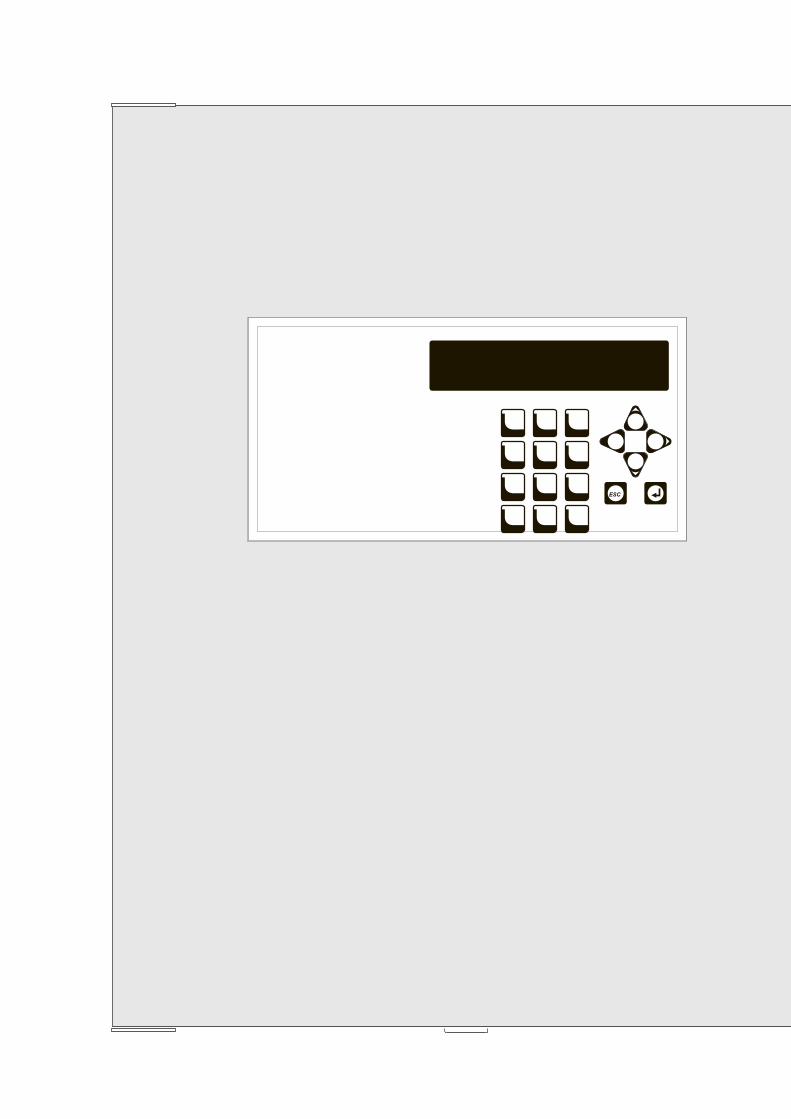
Figure 1 Front view of the FC510, FC520 control panel (a), and of Repeater FC500REP (b)

ESC
ABC DEF GHI
JKL MNO PQR
STU VWX YZ
1
4
7
2
5
8
0
3
6
9
ESC
F1
F2
F3
F4
MIC
FireClass
LAMPBUZZTEST
SILENCE
INVESTIGATE
SILENCEBUZZER
RESET
EVACUATE
MORE ALARMS
LOGIC UNITPRE-ALARM
LOST DEVICE
COMMUNICATOR
DAY MODE NAC FIRE OUTPUT
DISABLED HEARTH
SILENCE LOW BATTERY
TEST NO BATTERY
MAINS
FIRE
FAULT
COMMUNICATOR
MAINS
2 1
2
b)
2 2
2 1
23 5
1 4
11
PARTS IDENTIFICATION 11
+ -
RS48524V
7 8 9 10
6 23
7 7
7 7 7 714 1324
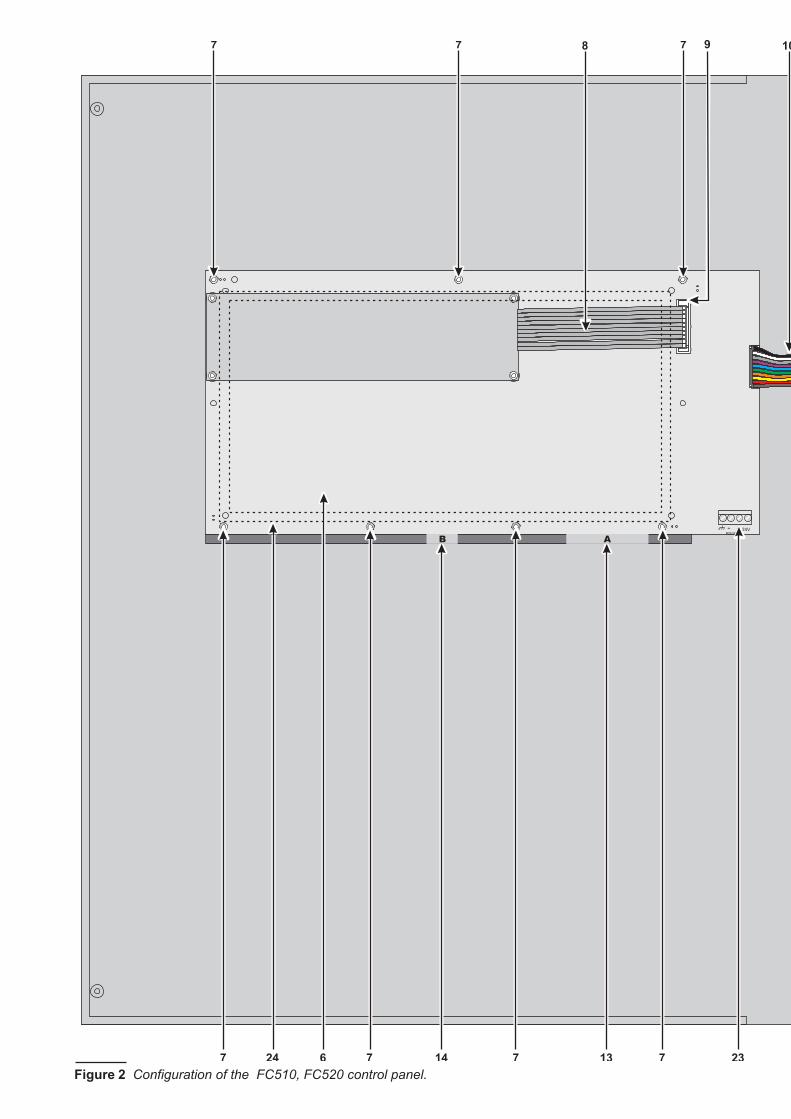
Figure 2 Configuration of the FC510, FC520 control panel.

AC/N FG +V GND
B+
L B–
GN
D
+V
AC/L
F10A/25ØV
LEFT
+ -
RS48524V+ L2 - + L2 - + L1 - + L1 -
RIGHT LEFT RIGHT LC24A
AUX24RAUX-RES
NCFIRENO C NC
FAULTNO C +
BAT2- +
BAT1-
PS1 PS2
OS
1
OS
2
OS
3O
S4
OS
5O
S6 O
S7
OS
8O
9
O10
O11
O12
O13
O14
O15
O16
+
NA
C-
FIR
E
+- N
AC
1
+- N
AC
2
+- N
AC
31
2V
17
0 12 15 12
19212220 1212 21
11
20 18
16
PARTS IDENTIFICATION 13

Description of Parts
This section describes the components of the FC500
serie Control panels, and FC500REP Repeater.
A The Repeater FC500REP has NOT
IMQ-SECURITY SYSTEM certification.
Unless otherwise stated, the numbers in boldface in this
Manual refer to the Tables ands Diagrams in this sec-tion.
The parts identification numbers in the diagrams go cloc-kwise.
P. Description
1 Surface Cable conduit entry
2 Door screws
3 LED label slots
4 KEYs label slots
5 Display
6 User interface board
7 Nuts to secure the User interface board on the
cover of Control Panel or Repeater
8 Flat cable: for the Display module board con-nection with User interface board
9 Jack for the connection between display mo-dule and User interface board
10 Flat cable: for the User interface board con-nection with Main board
11 Jumper to Default programming (Future use)
(Default//)
12 Anchor screw locations
13 Signalling LEDs Label
14 Identification Keys Label
15 Main Board
16 Switching power supply support
17 Switching power supply screw
14 Analogue Fire Panel FC500
2a)
2 2
2
1
6 23
+ -
RS48524V
7 7 7
7 7 7 714 1324
Figure 3 Configuration of the FC500REP Repeater a) frontplate (inside view); b) backplate.

P. Description
18 Switching power supply
19 Anchor for 230 V power supply wires
20 Batteries (NOT supplied):
FC510, FC520 = 2 da 12 V 17 Ah
(Accessory item: 2 da 12V 38 Ah -see figure 14-
21 Chased cable conduit entry
22 Thermal probe (accessory item)
23 Jack for the connection between the User in-terface to Repeater (RS485 interface acces-sory item)
24 Plastic frame (Spacer for User Interface PCB)
PARTS IDENTIFICATION 15
1
1 1
b)
12 12
12 1221
1
16 Analogue Fire Panel FC500
P. Description
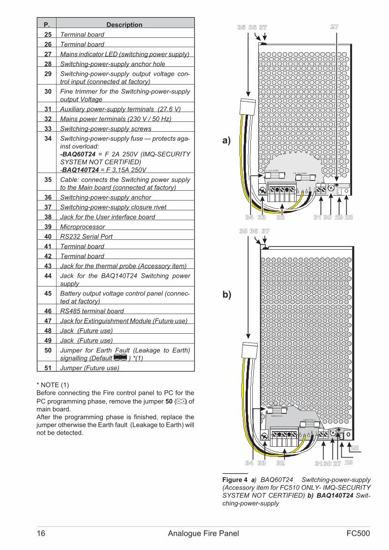
25 Terminal board
26 Terminal board
27 Mains indicator LED (switching power supply)
28 Switching-power-supply anchor hole
29 Switching-power-supply output voltage con-trol input (connected at factory)
30 Fine trimmer for the Switching-power-supply
output Voltage
31 Auxiliary power-supply terminals (27.6 V)
32 Mains power terminals (230 V / 50 Hz)
33 Switching-power-supply screws
34 Switching-power-supply fuse — protects aga-inst overload:
-BAQ60T24 = F 2A 250V (IMQ-SECURITY
SYSTEM NOT CERTIFIED)
-BAQ140T24 = F 3,15A 250V
35 Cable: connects the Switching power supply
to the Main board (connected at factory)
36 Switching-power-supply anchor
37 Switching-power-supply closure rivet
38 Jack for the User interface board
39 Microprocessor
40 RS232 Serial Port
41 Terminal board
42 Terminal board
43 Jack for the thermal probe (Accessory item)
44 Jack for the BAQ140T24 Switching power
supply
45 Battery output voltage control panel (connec-ted at factory)
46 RS485 terminal board
47 Jack for Extinguishment Module (Future use)
48 Jack (Future use)
49 Jack (Future use)
50 Jumper for Earth Fault (Leakage to Earth)
signalling (Default// ) *(1)
51 Jumper (Future use)
* NOTE (1)
Before connecting the Fire control panel to PC for the
PC programming phase, remove the jumper 50 (" ) of
main board.
After the programming phase is finished, replace the
jumper otherwise the Earth fault (Leakage to Earth) will
not be detected.
AC/N FG +V GND
B+
L B–
GN
D
+V
AC/L
F 3 . 1 5 A / 2 5 Ø V
F 6 . 3 A / 2 5 Ø V
AC/N FG +V GND
B+
L B–
GN
D
+V
AC/L
F4A/25ØV
F10A/25ØV
a)
b)
27
28293031323334
28
29273130323334
373635
35 36 37
Figure 4 a) BAQ60T24 Switching-power-supply
(Accessory item for FC510 ONLY- IMQ-SECURITY
SYSTEM NOT CERTIFIED) b) BAQ140T24 Swit-ching-power-supply
P. Description
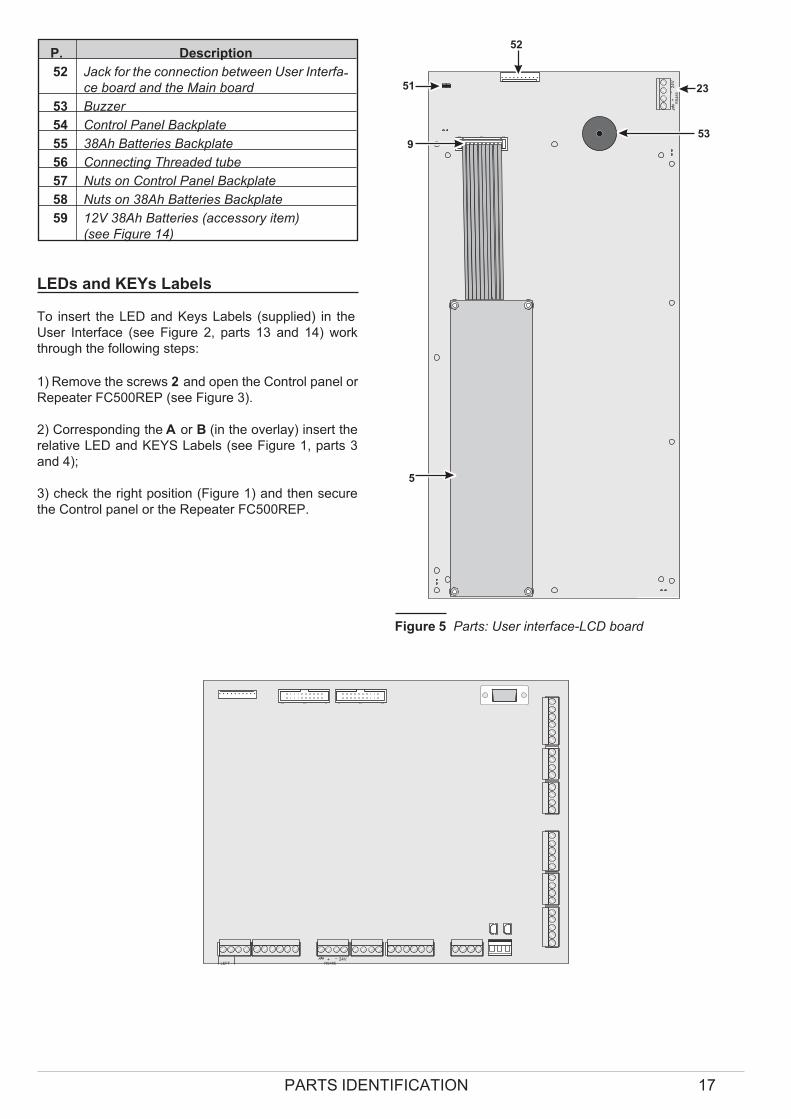
52 Jack for the connection between User Interfa-ce board and the Main board
53 Buzzer
54 Control Panel Backplate
55 38Ah Batteries Backplate
56 Connecting Threaded tube
57 Nuts on Control Panel Backplate
58 Nuts on 38Ah Batteries Backplate
59 12V 38Ah Batteries (accessory item)
(see Figure 14)
LEDs and KEYs Labels
To insert the LED and Keys Labels (supplied) in the
User Interface (see Figure 2, parts 13 and 14) work
through the following steps:
1) Remove the screws 2 and open the Control panel or
Repeater FC500REP (see Figure 3).
2) Corresponding the A or B (in the overlay) insert the
relative LED and KEYS Labels (see Figure 1, parts 3
and 4);
3) check the right position (Figure 1) and then secure
the Control panel or the Repeater FC500REP.
PARTS IDENTIFICATION 17
+-
RS
48
52
4V
5
9
51
53
23
52
Figure 5 Parts: User interface-LCD board
LEFT+ -
RS48524V+ L2 - + L2 - + L1 - + L1 -
RIGHT LEFT RIGHT LC24AAUX
24RAUX-RES
NCFIRE
NO C NCFAULT
NO C +BAT2
- +BAT1
-PS1 PS2
OS
1
OS
2
OS
3O
S4
OS
5O
S6 O
S7
OS
8O
9
O1
0O11
O1
2O
13
O1
4 O1
5
O1
6
+
NA
C
- FIR
E
+- N
AC
1
+- N
AC
2
+- N
AC
31
2V
38 11 40 41
47
42
46 44 4345 42
39
48
49 50
Figure 6 Identification of the parts: a) Main board .

Description of the Control keys
� Test, Silence Buzzer and Evacuate Control keys
ONLY can be activated without password (access
level L1), all the others Control keys can be activa-
ted with password (access level L2 and L3)
Lamp/Buzz/Test See table 4
Silence See table 4
Investigate See table 4
Silence Buzzer See table 4
Reset RESET will stop Alarm, Prealarm, Warning and
FAULT conditions. Access to this command is limited to
authorized personnel only (installer or user code PINs).
The system will reprocess any alarm, prealarm, war-ning or fault signal which is not cleared by RESET ope-rations. Command keys cannot be used when RESET
is running.
The repeaters FC500REP can be RESET by the instal-ler or user code PINs.
Evacuate See table 4
F1, F2, F3, F4 See table 4
18 Analogue Fire Panel FC500
KEY DESCRIPTION
Lamp/Buzz
Test
This key can be used to test the buzzer and LEDs . If this key is pressed (when the Control panel is
functioning as intended), all the LEDs will glow and the buzzer will emit a continuous beep.
Silence This key can be used to restore the Silenceable outputs to standby status. Silence status will be held
until the Silence key is pressed again in Day Mode, or if the Control panel is operating in Night
Mode, until the Night mode Silence time expires or until a new Alarm/Trouble condition is detec-ted.
Investigate This key can be used to refresh the “PreAlarm Time”: if this key is pressed during “PreAlarm”, the
remaining PreAlarm time will be increased with the programmed "Recognition delay".
Silence
Buzzer
Key to silence the local buzzer of the control panel: the buzzer will be operating every time a new
event will be activated
Reset This key can be used to reset the Fire detectors and restore all outputs to standby status (Supervi-sed/Silenceable outputs, NON-Supervised/Non-Silenceable outputs and Alarm zone outputs)
Evacuate key to activate the evacuation: if this key is pressed for over 2 seconds, the system will generate an
alarm.
F1, F2, F3, F4 Function keys of the Display; their function will be various according to different screen of display
Table 4 Description of the keys
INSTALLATION
! Installation of this system must be carried out
strictly in accordance with the instructions in
this section, and in compliance with the local
safety regulations in force.
To install the control panel work through the following
steps:
� Choose suitable mounting locations for the Control
panel, detectors, fire warning and fire control devi-ces.
� Lay the cables between the Control panel and the
system peripherals.
� If necessary, install any accessory modules.
� Before mounting the Control panel to the wall, insert
the LED and Keys Labels (supplied) in the Interface
User (see pag.17).
� Carry out the necessary connections, leaving the po-wer-supply connection until last.
� Program the Control panel in accordance with the in-structions in the “PROGRAMMING” section.
� Test the entire system (Control panel, detectors, fire
warning and fire control devices).
� Accessory Modules should be installed before mo-
unting the Control panel to the wall.
Installing accessory boards
! Ensure that the Control panel power supply
(Mains and Batteries) has been disconnected
before installing any accessory Modules.
A The Repeater FC500REP has NOT
IMQ-SECURITY SYSTEM certification.
Installing FC500REP Repeaters
Repeaters can be wall mounted, or flush mounted to an
ave® BL08 outlet box (or similar).
Work carefully through the following steps.
1. Lay the connection cables (refer to “Connecting
Repeaters”).
2. Remove the screws 2 (see Figure 4) and open the
Repeater FC500REP.
3. If you are flush mounting the Repeater, go to step
5. If you are wall mounting the Repeater, drill the
anchor screw holes 12.
4. Pull the wires through the wire entry 21 , then, using
the anchor screws, secure the Repeater to the wall.
5. Complete the connections to the terminal board 23
of the RS485 Interface, as described in the “Con-necting Repeaters” section.
6. Set the Repeater Address.
Installing the FC500 Slave control panel
See "Installing the Control panel paragraph".
Installing the Control panel
Work carefully through the following steps (see the Fi-gures 1, 2 and 3).
1. Remove the screws (2) and open the Control panel.
2. Drill the anchor screw holes.
! Check for water pipes and electrical wiring be-fore drilling.
3. If necessary, using a hammer or similar tool, remo-ve the surface conduit wire knockouts 1.
� The cable conduit union with the case must be se-
cured by HB Flame Class (or higher) lock nuts.
4. Pull the wires through the chased wire entry 21
then, using the anchor screws, secure the backpla-
te to the wall.
INSTALLATION 19

Description of the Terminals
This section describes the Control panel terminals.
�Main Board terminals
+L1-/LEFT (+)Loop 1-Positive signal, left side.
(-)Loop 1-Negative signal (return), left side.
+L1-/RIGHT (+)Loop 1-Positive signal, right side.
(-)Loop 1-Negative signal (return), right side.
+L2-/LEFT (+)Loop 2-Positive signal, left side.
(-)Loop 2-Negative signal (return), left side.
+L2-/RIGHT (+)Loop 2-Positive signal, right side.
(-)Loop 2-Negative signal (return), right side.
� Each Loop supports 250 (Analogue detectors,
Input modules, Conventional Zone modules, Ma-
nual callpoints, Output modules and Sounders). In
all the control panel supports up to 500 devices
with 2 Loop.
LC Conventional Input Line - Supervised and
Bypassable — This line supports 30 conventional fire
devices (Optic Smoke detectors, Heat detectors, Ma-
nual callpoints).
Connect terminal [LC] to ground terminal [ M]) using a
3900 ohm resistor (orange-white-red). A 680 ohm resi-
stance (normal value for Fire detectors) parallel to the
3,900 ohm resistor will activate the programmed actions
and preset times of the Conventional Line outputs and the
Non-supervised output (terminals NC, NO and C).
� The Conventional Line supports 30 Conventional
detectors. ATTENTION: DO NOT connect more
than 500 detectors and/or manual call points to
each main PCB.
[M] Negative.
485 Serial Bus Terminals for FC500REP repeater pa-nels (maximum 8) and FC500 as Slave panels (maxi-mum 7). Serial bus terminals [+] and [-]; 27.6 V power
voltage terminals [M] and [24V].
AUX Auxiliary power 24 V Power supply to devices that
operate at 24 V (powered by the standby batteries):
� Positive (27.6 V) on terminal [24A];
� Negative on terminal [M].
AUX-RES Auxiliary power 24 V (1A max). The
system will interrupt power from terminal [24R] during
Reset. Power supply to devices that operate at 24 V
(powered by the standby batteries):
� Positive (27.6 V) on terminal [24R];
� Negative on terminal [M].
[NC][NO][C] FIRE Non-supervised fire output. Dry
contact relay for non-supervised devices:
� During standby status —— terminal [C] closes to ter-minal [NC];
� In the event of fire —— terminal [C] closes to terminal
[NO].
[NC][NO][C] FAULT Non-supervised fault output. Dry
contact relay for non-supervised devices:
� During standby status —— terminal [C] closes to ter-minal [NC];
� In the event of fault —— terminal [C] closes to termi-
nal [NO].
A IMQ-SECURITY SYSTEM cerification applies
ONLY when, FAULT output is not J (EN 54-1) type,
therefore this output MUST NOT UTILIZED to ma-nage Fault transmission devices.
+BAT2- Terminals to connect the batteries inside the
FC500 control panel (see Figure2).
+BAT1- Terminal to connect remote batteries or Po-wer supply.
PS1 BAQ140T24 power supply first connector.
PS2 BAQ140T24 power supply second connector.
OS1...OS8 Programmable, Silenceable, Bypassa-
ble, Supervised Outputs.
These are normally-open terminals (open-collector)
which close to ground when the connected event will
active. These terminals will remain closed to ground
even after the generating event has ended. These out-
puts can be forced to standby (Not programmable
polarity) by resetting the control panel .
� These outputs can be bypassed via the DISABLE
menu.
Connect an EOL 27.000 ohm resistor between termi-
nals [OS] and [M] of these outputs. This will allow the
control panel to detect and signal when the outputs are
shorted and/or open.
� NOTE: The EOL resistor must be connected to
the last device on the Supervised output. Connect
a diode (1N4002 or 1N4007) in series to the devi-ces connected to these outputs.
O9...O16 Programmable, Silenceable, Bypassable
NOT Supervised outputs —— These are nor-
mally-open terminals (open-collector) which close to
ground when the connected event will active. These ter-
minals will remain closed to ground even after the gene-
rating event has ended. These outputs can be forced to
standby (Not programmable polarity) by resetting the
control panel.
20 Analogue Fire Panel FC500

-NAC FIRE+ Type C output (EN54-1). - Silenceable,
Bypassable, Supervised —— Terminals for supervi-sed devices activated by positive (24 V):
� During ALARM status —— positive (27.6 V) on ter-minal [+]; negative on terminal [-].
� During STANDBY status —— negative on terminal
[+]; positive (27.6 V) on terminal [-].
� This output can be bypassed via the DISABLE menu.
ALARM status will activate this non-programmable out-put.
[12V] [M] Auxiliary power 12 V . Power supply to de-vices that operate at 12V (powered by the standby bat-teries and protected by self recover termic fuse):
� Positive (13.8 V) on terminal [12V];
� Negative on terminal [M].
Max current on terminal [12V] must not exceded
200mA.
NAC1 NAC2 and NAC3 Supervised/Silencea-
ble/Bypassable Programmable Alarm Outputs.
These Outputs are for the Alarm signalling devices.
Operating principles:
� in Standby status, these Outputs will be INACTIVE
(read on for details);
Output INACTIVE: negative pull-down to 0 V on [+] termi-nal; positive pull-up to 27.6 V on the [–] terminal.
Output ACTIVE: positive pull-up to 27.6 V on the [+] ter-minal; negative pull-down to 0 V on the [–] terminal.
� NAC1, NAC2 and NAC3 will restore to standby when
the Control panel Resets.
� NAC1, NAC2 and NAC3 can be Silenced (forced to
standby).
The NAC Outputs will hold standby status for the pro-grammed Silence Time. If Alarm conditions are pre-sent when the programmed Silence Time expires,
they will re-activate.
A NAC1, NAC2 and NAC3 accept devices that ope-rate within SELV limits ONLY.
A IMQ-SECURITY SYSTEM cerification applies
ONLY when, NAC1, NAC2, NAC3, OS1, OS2,
OS3, OS4, OS5, OS6, OS7, OS8, O9, O10, O11,
O12, O13, O14, O15, O16 and RELAY FIRE out-
puts are not C , E , J , G (EN 54-1) type,
therefore these outputs MUST NOT UTILIZED to
manage Fire Alarm devices and/or Fire Alarm
Transmission devices and/or Fire Fault Transmis-
sion devices and/or Automatic Fire Alarm Systems.
The System Wiring
� Use shielded cable only for all connections, with
one end of the shield connected to the Control pa-
nel negative terminal and the other left free.
! High Voltage leads (230 V) must be bunched se-parately from Low Voltage leads (24 V). All le-ads must be bunched in such a way as to avoid
contact with other wiring and components.
� Connecting Addressable Analogue Devices
The control panel has 2 loops for addressable analogue
devices.
Each loop supports 250 addressable analogue fire de-tectors and ananalogue devices (Input modules, Con-ventional Zone modules, Output modules).
You must assign a DIFFERENT address to each detec-tor on the loop.
You can use 2 or 4 wires for the loop connections.
NOTE: The loop connection type must be specified du-
ring the programming phase.
Figure 8(1) illustrates the 2-wire connection to Loop 1.
Figure 8(2) illustrates the 4-wire connection to Loop 1.
� The 2 wire connection does not allow more than 32
detectors per loop.
� The 4 wire connection does not allow T connec-tions (An insulators is necessary for 32 detectors
max.)
INSTALLATION 21
Osx
27,6V
FireClass
1N4007
LOAD
27K
SUPERVISED
Figure 7 OSx Outputs connecting

� Connecting Conventional Devices
Connect Conventional devices to terminals [M] and
[LC]. Fire detectors and Manual call point.
Connect the Conventional Fire detectors in parallel to
terminals [LC] and [M].
22 Analogue Fire Panel FC500
L-L-
L-L-
L-L-
L+L+
L+L+
L+L+
L-L-
L+L+
L- L-L+ L+
A
BB
B
B B
B
A
FireClass
L-L-
L-L-
L-L-
L+L+
L+L+
L+L+
L-L-
L+L+
+L2 -
A
C
BB
BB
A
FireClass
1) 2)
+L2 - +L1 - +L1 -
LEFT RIGHT LEFT RIGHT
+L2 - +L2 - +L1 - +L1 -
LEFT RIGHT LEFT RIGHT
Figure 8 1) Wiring diagram of a 2-wire connection - 2) Wiring diagram of a 4-wire connection: a) Insulators; b) Com-patible analogue devices (Fire detector, Input modules, Output modules, Conventional Zone modules, Manual callpo-ints); c) T connection.
A+
A+
A+
A+
NA
NA
C
C
B+
B+
B+
B+
LC
LC
ConventionalDetector
ConventionalDetector
ConventionalDetector
ConventionalDetector
Manual Call Point
Manual Call Point
680 �
680 �
EOL End ofline resistor(2K7 1/4 W)
A)
B)
EOL End ofline resistor(2K7 1/4 W)
FireClass
FireClass
Figure 9 Wiring diagram of Conventional device connections

The resistor (3,900 ohm) connected to these terminals
must be moved to the terminals indicated in the instruc-tions of the last device on the Conventional Line (see
figure 9a).
� Connecting Repeater and Slave Control panel
An example of how to connect two FC500REP repea-ters and two FC500 SLAVEs is shown in Figure 10.
The RS485 port of the FC500 (terminals [M], [+], [-]
and [24V]) accepts up to 8 FC500REP repeaters and
up to 7 FC500 SLAVEs, so a panel will be configured as
a "Master" control panel while the others seven will be
configured as "Slave" control panel; the eight Repea-ters will be the Repeaters of the "Master" control panel.
� Assign an address to FC500REP repeaters ( see
the procedure "Programming from the Panel"
page 46).
A The Repeater FC500REP has NOT
IMQ-SECURITY SYSTEM certification.
Terminals [+] and [-] supply the power (27.6 V) to the re-peater panels (see figure 10,11).
When a mains fault occurs, the Repeaters considerably
decreases the absorbed power, switching off the LCD
display backlighting (the LCD display backlighting
switches on again, for 20 sec. when a key will be pres-sed). But the absorption of the Repeaters connected to
the control panel, will contribute to run down the backup
batteries, and so the decrease of the Stand-by supply
time of the system.
When one control panel only is in the system all the Re-peaters must be supplied by the control panel itself, un-less a Power supply Station is in the system.
When several Control panels are in the system, the
Repeaters supply Load can be shared between these
Control panels (see Figure 11).
� The control panel [24V] terminals must not be con-
nected between them, because the switching Po-
wer supply cannot work in parallel and the entry in
protection status (OFF) can be produced with the
effect of overloading the switching Power supply
still working.
Use shielded cable only, with one end of the shield
connected to the "Master" Control panel Negative
terminal and the other left free; the continuity, bet-
ween several segments of connection must be se-
cured (see Figure 11).
� Connecting Output Devices
The control panel has 8 supervised outputs, 8 NON su-pervised outputs and 4 Bell outputs (supervised and
silenceable) .
INSTALLATION 23
24V
RS
48
5
24V
RS485
24V
RS485
24V
RS485
24V
RS485
Ma
inB
oa
rd
FC500 SlaveFC500 SlaveFC500REPFC500REP
Connect to theearth connector
Figure 10 Wiring diagram of two FC500REP Repeaters and two FC500 Slave Control panels connected to the RS485
24V
RS485
24V
RS485
24V
RS485
24V
RS485
Master Panel Repeater 1 Slave Panel Repeater 2
Figure 11 Network connection example: the Repeaters supply load is shared on several Control panel. In this case
the“Repeater 1” is supplied by "Master" panel while the “Repeater 2” is supplied by ”SLAVE” control panel.
� NOTE: Output devices can be connected to the loops
by means of Output modules.
� Bell Outputs
The Bell outputs are indicated by the letter NAC and
their address number.
� The NAC1, NAC2 and NAC3 Bell Outputs are Pro-grammable, Supervised, Silenceable, Bypassable.
� The terminal marked "-NAC FIRE +"is a Bell output
(C type, EN54-1),Supervised, Silenceable, Bypassa-ble but Non-programmable. This output will activate
when the Control panel goes into Alarm status.
The Bell outputs can be forced to standby status by me-
ans of the SILENCE button. Once an alarm has been
acknowledged, you can silence the audible signalling
devices and leave the visual signalling devices active
until the alarm conditions cease.
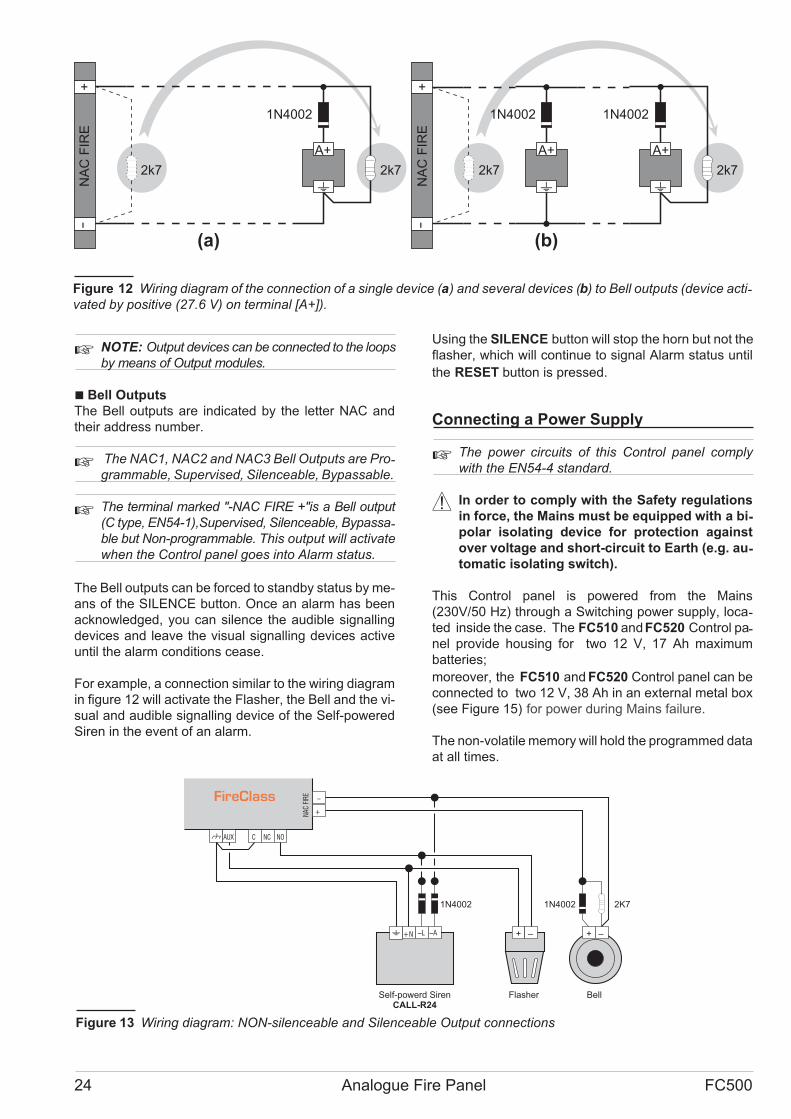
For example, a connection similar to the wiring diagram
in figure 12 will activate the Flasher, the Bell and the vi-
sual and audible signalling device of the Self-powered
Siren in the event of an alarm.
Using the SILENCE button will stop the horn but not the
flasher, which will continue to signal Alarm status until
the RESET button is pressed.
Connecting a Power Supply
� The power circuits of this Control panel comply
with the EN54-4 standard.
! In order to comply with the Safety regulations
in force, the Mains must be equipped with a bi-polar isolating device for protection against
over voltage and short-circuit to Earth (e.g. au-tomatic isolating switch).
This Control panel is powered from the Mains
(230V/50 Hz) through a Switching power supply, loca-ted inside the case. The FC510 andFC520 Control pa-nel provide housing for two 12 V, 17 Ah maximum
batteries;
moreover, the FC510 and FC520 Control panel can be
connected to two 12 V, 38 Ah in an external metal box
(see Figure 15) for power during Mains failure.
The non-volatile memory will hold the programmed data
at all times.
24 Analogue Fire Panel FC500
+
-
A+ A+A+
(a) (b)
2k72k7 2k72k7
1N4002 1N40021N4002
NA
CF
IRE
+
-
NA
CF
IRE
Figure 12 Wiring diagram of the connection of a single device (a) and several devices (b) to Bell outputs (device acti-vated by positive (27.6 V) on terminal [A+]).
AUX NC NO
+
–
C
+N –L –A + –+ –
NA
CFI
RE
1N4002 1N4002 2K7
Self-powerd SirenCALL-R24
Flasher Bell
FireClass
Figure 13 Wiring diagram: NON-silenceable and Silenceable Output connections
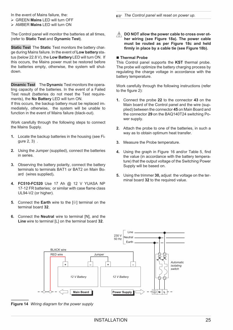
In the event of Mains failure, the:
� GREEN Mains LED will turn OFF
� AMBER Mains LED will turn ON
The Control panel will monitor the batteries at all times,
(refer to Static Test and Dynamic Test).
Static Test The Static Test monitors the battery char-ge during Mains failure. In the event of Low batterysta-
tus (below 22.8 V), the Low BatteryLED will turn ON. If
this occurs, the Mains power must be restored before
the batteries empty, otherwise, the system will shut-
down.
Dinamic Test The Dynamic Test monitors the opera-ting capacity of the batteries. In the event of a Failed
Test result (batteries do not meet the Test require-ments), the No Battery LED will turn ON.
If this occurs, the backup battery must be replaced im-mediately, otherwise, the system will be unable to
function in the event of Mains failure (black-out).
Work carefully through the following steps to connect
the Mains Supply.
1. Locate the backup batteries in the housing (see Fi-gure 2, 3) .
2. Using the Jumper (supplied), connect the batteries
in series.
3. Observing the battery polarity, connect the battery
terminals to terminals BAT1 or BAT2 on Main Bo-ard (wires supplied).
4. FC510-FC520 Use 17 Ah @ 12 V YUASA NP
17-12 FR batteries; or similar with case flame class
UL94-V2 (or higher).
5. Connect the Earth wire to the [Q] terminal on the
terminal board 32.
6. Connect the Neutral wire to terminal [N], and the
Line wire to terminal [L] on the terminal board 32.
� The Control panel will reset on power up.
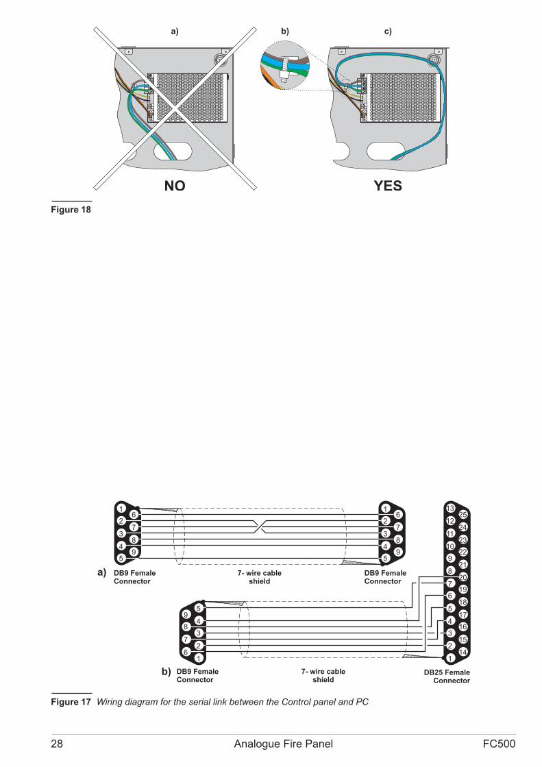
! DO NOT allow the power cable to cross over ot-
her wiring (see Figure 18a). The power cable
must be routed as per Figure 18c and held
firmly in place by a cable tie (see Figure 18b).
� Thermal Probe
This Control panel supports the KST thermal probe.
The probe will optimize the battery charging process by
regulating the charge voltage in accordance with the
battery temperature.
Work carefully through the following instructions (refer
to the figure 2):
1. Connect the probe 22 to the connector 43 on the
Main board of the Control panel and the wire (sup-plied) between the connector 45 on Main Board and
the connector 29 on the BAQ140T24 switching Po-wer supply.
2. Attach the probe to one of the batteries, in such a
way as to obtain optimum heat transfer.
3. Measure the Probe temperature.
4. Using the graph in Figure 16 and/or Table 5, find
the value (in accordance with the battery tempera-ture) that the output voltage of the Switching Power
Supply will be based on.
5. Using the trimmer 30, adjust the voltage on the ter-minal board 32 to the required value.
INSTALLATION 25
LMain Board N
Automaticisolatingswitch
+ –
12 V Battery
Line
Neutral
Earth
230 V50 Hz
+ –
12 V Battery
Power Supply
RED wire
BLACK wire
Jumper
Figure 14 Wiring diagram for the power supply

26 Analogue Fire Panel FC500
AC/N FG +V GND
B+
L B–
GN
D
+V
AC/L
F10A/25ØV
LEFT
+ -
RS485
24V+ L2 - + L2 - + L1 - + L1 -
RIGHT LEFT RIGHTLC
24A
AUX
24R
AUX-RES
NC
FIRE
NO C NC
FAULT
NO C +
BAT2
- +
BAT1
-
PS1 PS2
OS
1
OS
2
OS
3O
S4
OS
5OS
6
OS
7
OS
8O
9
O10
O11
O12
O13
O14 O
15
O16
+
NA
C-
FIR
E
+- N
AC
1
+-
NA
C2
+-
NA
C3
12V
+ -RS485
24V
54 57 56
5855
59 59
CONNECTION BETWEEN CONTROL PANEL BACKPLATE and
12V 38Ah BATTERIES BACKPLATE -Accessory Item-
1 1
12
12
12
12
Figure 15 Control Panel and 38Ah Batteries metal Box connection (accessory item).

Installing the 38Ah battery metal Box
Work carefully through the following steps (see Figure
15).
1. Remove the screws (2) and open the metal box.
2. Drill the anchor screw holes.
! Check for water pipes and electrical wiring be-fore drilling.
3. If necessary, using a hammer or similar tool, remo-ve the surface conduit wire knockouts 1.
4. Secure the metal backplate to the wall
� The cable conduit union with the case must be se-
cured by HB Flame Class (or higher) lock nuts.
Pull the wires through the chased wire entry 1 and con-nect them. See paragraph: Connecting a power supply.
Maintenance
The following operations must be carried out regularly.
A Using a damp cloth (DO NOT USE SOLVENTS OF
ANY KIND), remove dust from the Control panel case.
B Using the Lamp/Buzz/Test key, check that the
LEDs and buzzer are functioning properly.
C Ensure that the batteries are sufficiently charged and
functioning properly. If not, replace them immediately.
D Ensure that all cables and connections are intact.
E Ensure that there are no unrelated objects inside the
Control panel case.
� Points A and B may be carried out by users.
Points C, D and E must be carried out by qualified
persons only.
INSTALLATION 27
-10 -5 0 5 10 15 20 25 30 35 40 45 50
26,0
27,0
28,0
29,0
VO
LTA
GE
(V)
TEMPERATURE (°C)
a)
27,4
22
Figure 16 Switching Power Supply Output Voltage graph. To find the Output Voltage using the graph: — indicate the
Probe temperature on the TEMPERATURE (°C) axis; draw a line from the temperature value point up to the curve a);
draw a line from the intersection point across to the VOLTAGE (V) axis; adjust the Output Voltage of the Switching Po-wer Supply to the resultant value. For example, if the Probe temperature is 22 °C, the Output Voltage of the Switching
Power Supply must be set at 27.4 V.
TEMPERATURE (°C) -10 -5 0 5 10 15 20 25 30 35 40 45 50
VOLTAGE (V) 29,0 28,8 28,6 28,2 28,0 27,8 27,4 27,2 27,0 26,8 26,6 26,4 26,2
Table 5 Switching Power Supply Output Voltage chart. To find the Output Voltage using the chart: — select the nea-rest value to the Probe temperature on the TEMPERATURE (°C) row; read the respective value on the VOLTAGE (V)
row; adjust the Output Voltage of the Switching Power Supply to the indicated value. For example, if the Probe tempe-rature is 22 °C, the Output Voltage of the Switching Power Supply must be set at 27.4 V.
28 Analogue Fire Panel FC500
5
4
6
5
4
3
2
1
9
18
8
19
17
16
15
14
7
20
21
22
23
24
25
6
3
7
2
8
9
10
11
12
13
1
a)
b) DB25 FemaleConnector
5 5
4 49 9
8 8
7 7
6 6
3 3
2 2
1 1
DB9 FemaleConnector
7- wire cableshield
DB9 FemaleConnector
7- wire cableshield
DB9 FemaleConnector
Figure 17 Wiring diagram for the serial link between the Control panel and PC
AC
/NFG
+V
GN
D
B+
L
B–
GND
+V
AC
/L
F3
.1
5A
/2
5Ø
VF
6.3
A/2
5Ø
V
AC
/NFG
+V
GN
D
B+
L
B–
GND
+V
AC
/L
F3
.1
5A
/2
5Ø
VF
6.3
A/2
5Ø
V
a) b) c)
NO YES
Figure 18

PC PROGRAMMING
You can program this system from the Control panel or
from a computer, using the FireClass500 Software
Console, inside the Bentel Fire Suite.
This section describes how to program the system from
a computer. If you intend programming the system from
the Control panel refer to the “PROGRAMMING FROM
THE PANEL” section.
Introduction
The FC500 software console contains:
� FC500: the application to manage and program the
FC500 series control panels.
� LangBuilder: Language application (customizes
system terminology) (language used in the software
Console and in the display of the Control Panel and
Repeater).
Installation
Work carefully through the following steps to install the
FC500 software applications.
� Run the Setup.exe application contained in the
CdRom "Fire Suite".
� Select a folder for the FC500 software applications.
� Run as Administrator.
Select language
You can select the language of the FC500 Software,
from the Languages provided, or use the
LangBuilder application to customize the application
terminology.
To Select the application language:
� Run the FC500 Software application;
� Select Options from the Main window;
� Select Language from the drop-down menu to open
a window with the language list;
� Select a language from the Language list;
� Click-on � OK,
The selected language will be immediately initialised.
� At the first start up, FireClass Console software will
ask to choose the language.
Software window Look
To modify the look of the FC500 software window, click-
on Key "Avalaible Skin" in the left bottom of the Main
window or click-on right key on the title bar. This option
allow you to modify the look of the window in the offer
range (see Figure 19).
Control panel connections
If you are using the Supervisory, Management, Downlo-ading and Log Management functions, the control panel
must be connected to your PC in local communication
or remote (Future Use) by PSTN line, GPRS or LAN.
To connect the control panel in local:
(see note page n. 16)
Using a CVSER/9F9F cable (accessory item) or similar
cable (see figure 16), connect the control panel serial
port (refer to “PARTS IDENTIFICATION”) to a serial
port on your PC.
� Select the PC serial port from the Option menu
(Choose serial port ) and then Click-on � OK,.
For 25 pin serial ports, use an ADSER/9M25F adapter
(accessory item) or make a cable as per figure 16b.
If the control panel is not connected to your PC when
you start the communication, the following warning will
be shown: "Communication error! Check serial link"
If the serial port for the local communication is invalid,
the following warning will be shown: "Cannot open se-rial port".
PC PROGRAMMING 29
Figure 19 To modify the window look (Available
skins).

Main window
The FC500 Software opens on the Main window (see
fig. 20). The following section describes the File, Com-munication, Options, DataBase and Help menus.
� Icons description
Click-on this icon under "Panel 1" the window "New
panel" will open, Figure 20. Here, you can choose the
type of control panel, the Firmware Release, the control
panel name and the possible address if more control
panel are present in the system.
Description of the icons under "Panel 1"
� Click-on this icon and then confirm to restore the
factory defaults.
� Click-on this icon to download the programming
(via serial link) to the connected control panel.
� Click-on this icon to upload all the programming
(via serial link) of the connected control panel.
� Click-on this icon to see the firmware version of
MainBoard , Loop controller and User Interface.
� Click-on this icon to add a new Loop expansion
board.
� Click-on this icon to remove a Loop expansion
board.
� Click-on this icon to open the Data cu-
stomer window.
� Click-on this icon to insert-modify the
Installer Password.
� Selected a stored customer, click-on
this icon to delete the customer, after con-
firm: OK.
� Click-on this icon, in a Master control
panel, a window in Figure 19 will be shown.
In this window, a Slave control panel can
be inserted with a name and an address,
the same programmed address from the
user interface of Slave control panel (see Program-ming from the panel).
� Click-on this icon to remove the selected Slave
control panel, after a request of confirmation.
� File
The File options (New, Open, Save, Close,
Export/Import configuration file, Exit) will allow you
to manage customer account data.
New (New customer) The New option creates a
New customer and restore the factory default to all pro-gramming parameters.
Open Click-on "Open", to retrieve customer data from
the "Customer List" (see Figure 21). Click-on selected
customer and after confirm: � OK.
Save If a new customer is programmed or the exiting
data customer are modified, click-on "Save" a new cu-stomer or the new configuration will be saved.
Close Click-on "Close", the selected customer will be
closed.
Exit Click-on "Exit", the FC500 software will be closed.
Export configuration file: Click-on this option, all the
data customer will be exported in a single file.
30 Analogue Fire Panel FC500
Figure 20 New panel window(Type of control panel)
Figure 21 "Open" window .
Figure 22 Firmware Upgrade window
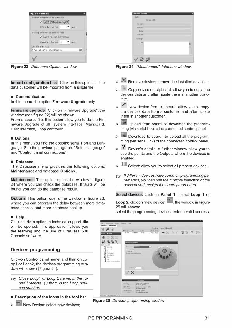
Import configuration file: Click-on this option, all the
data customer will be imported from a single file.
� Communication
In this menu: the option Firmware Upgrade only.
Firmware upgrade Click-on "Firmware Upgrade": the
window (see figure 22) will be shown.
From a source file, this option allow you to do the Fir-
mware Upgrade of all system interface: Mainboard,
User interface, Loop controller.
� Options
In this menu you find the options: serial Port and Lan-
guage. See the previous paragraph: "Select language"
and "Control panel connections".
� Database
The Database menu provides the following options:
Maintenance and database Options .
Maintenance This option opens the window in figure
24 where you can check the database. If faults will be
found, you can do the database rebuilt.
Options This option opens the window in figure 23,
where you can program the delay between more data-base checks, and more database backup.
� Help
Click on Help option; a technical support file
will be opened. This application allows you
the learning and the use of FireClass 500
Console software.
Devices programming
Click-on Control panel name, and than on Lo-op1 or Loop2, the devices programming win-dow will shown (Figura 24).
� Close Loop1 or Loop 2 name, in the ro-
und brackets ( ) there is the Loop devi-
ces number.
� Description of the icons in the tool bar.
� New Device: select new devices;
� Remove device: remove the installed devices;
� Copy device on clipboard: allow you to copy the
devices data and after paste them in another custo-mer.
� New device from clipboard: allow you to copy
the devices data from a customer and after paste
them in another customer.
� Upload from board: to download the program-ming (via serial link) to the connected control panel.
� Download to board: to upload all the program-ming (via serial link) of the connected control panel.
� Device's details: a further window allow you to
see the points and the Outputs where the devices is
enabled.
� Select: allow you to select all present devices.
� If different devices have common programming pa-rameters, you can use the multiple selection of the
devices and assign the same parameters.
Select devices Click-on Panel 1, select Loop 1 or
Loop 2, click on "new device" , the window in Figure
25 will shown:
select the programming devices, enter a valid address,
PC PROGRAMMING 31
Figure 23 Database Options window. Figure 24 "Maintenace" database window.
Figure 25 Devices programming window

and after click-on � OK to put the devices in configura-tion. For others devices, repeat the same procedure.
Remove devices Select the device, therefore click-on
"Remove device" , and confirm the choose � OK.
Loop Loading At the end of "Device programming
window", Figure 25, there is a Loop Loading section.
Here, the "Loop drain" and the "Signal drain" will be
shown . On the right, the "Loop drain in stand by", the
"Loop drain in alarm (50%)", and the "battery needed"
will be shown.
The percentage shown in the "Loop drain in alarm
(50%)" is the programmed value in "Battery calculation"
an option of Configuration menu (see dedicated para-graph).
� Parameters detectors programming
Click-on device in configuration, the relative
programming window will shown (every device
has the dedicated programming window).
For the detectors (see figure 26);
in the Multiple sources section:
� Enable: a tick [�] indicates if the detector is
enable.
� LED Blinking: a tick [�] indicates if the
LED detector is enable or disable.
� Label: this is for the editable device-label.
The system will use the label as the device
identifier.
� Address: in this field you can modify the ad-
dress of the detector;
Options section:
� assigned zones: each fire detector, Input mo-dule and Manual call Point can be associated
with 1 of the avalaible software zones (64 for
FC510, 128 for FC520 control panel). If a devi-
ce goes into ALARM status, all the zones it is
connected to (assigned zones) will also go into ALARM
status.
� Base In this section it is possible to select the base
for the detector (click on available bases).
� Processing section:
Processing: this determines the actions the control
panel will perform when the device threshold is exce-eded.
Drift Compensation: Drift compensation effects analo-
gue smoke sensors only.
It will supply a precise analysis about dust accumula-
tion, and therefore, the alarm threshold will be modified
accordingly.
32 Analogue Fire Panel FC500
Detector
Class
Typical application
Temperature
°C
Max. Application
Temperature
°C
Min.Static
Response
Temperature
°C
Max.Static
Response
Temperature
°C
A1 25 50 54 65
A2 25 50 54 70
B 40 65 69 85
C 55 80 84 100
D 70 95 99 115
E 85 110 114 130
F 100 125 129 145
G 115 140 144 160
Table 6 Detector classification Temperature - Detector shall conform to one or more of the following classes: A1,
A2, B, C, D, E, F o G . Manufacturers may optionally give additional information concerning the type of response exhi-bited by the detector, by adding the suffix S or R to the above classes.
Detectors, with a suffix S to their class, do not respond below the minimun static response temperature, even at high
rates of rise of air temperature.
Detectors, with a suffix R to their class, incorporate a rate of rise characteristic, which meets the response time requi-rements for high rates of rise of air temperature even when starting at air temperature substantially below the typical
application temperature (EN54-5:2000).
Figure 26 Detector Disablement confirmation window.

Use zone setting: the detector uses the parameters
of the assigned zone; if this options is disabled, the pro-
cessing type will be selected.
Prealarm - the control panel will activate the ALARM
delay;
Warning - the control panel will activate a WARNING
signal.
Operating mode Heat detector:
Day mode-Night mode for Temperature detector (see
table 6).
Operating mode Smoke detector: Day mode-Night
mode for Smoke and Heath detectors:
� Default: for smoke detectors only (813P) and for
Smoke and Heath detectors only (801PH)
� Enhanched: (for Smoke and Heath detectors only)
� Sensitivity: Sensitivit can set:
Low, Medium and High.
� Click-on red bar to open or close the relative sec-
tion of parameters programming
� If a detector linked to an Output or Input-Output Mo-dule, will be disabled (remove a tick [�] in the proper
section), a window will shown to ask confirmation.
Click on Detail to see further data (Figure 26).
� Input modules programming
Click-on an entered Input Modules, the relative pro-gramming window will shown as per the following de-scription.
Input module section: as per the same Detectors
section;
Assigned zones: as per the same Detectors section;
Operating mode section: select the operating mode
style: B, C, D, E.
There are two operating modes:
A= 4 wires connection mode (Loop)
B= 2 wire connection mode;
and there are 4 operating mode style: B, C, D, E;
� B style: two wire connection mode: the short-circuit
condition as an Alarm condition.
� C style: two wire connection mode: the short-circuit
condition as a Fault condition.
� D style: Four wire connection mode (Loop): the
short-circuit condition as an Alarm condition
(Future use).
� E style: Four wire connection mode (Loop): the
short-circuit condition as a Fault condition
(Future use).
Processing section: as per the same Detectors section.
� Output modules programming
Click-on an entered Output Modules, the relative pro-gramming window will shown as per the following de-scription.
Output module section: as per the same Detectors
section;
Assigned zones: each Output module can be associa-ted with up to 4 of the 64 avalaible software zones for
FC510 control panel, (128 for FC520). An Output mo-dule will activated when the zones where is enabled will
go into ALARM status.
Base In this section it is possible to select the base for
the Output module, click on available bases (for
FC430SAM and FC430SAB only).
Assigned points: each Output module can be associa-ted with 3 Input Points. If any one of its Input Points
goes into ALARM status, the Output module will activa-te. For each Point it is necessary to indicate:
� the loop the device is connected to (1 or 2);
� the device address.
Options section: this option will allow you to select the
conditions that will activate the output module:
� Zone warning, Zone fault, Zone Prealarm, Zone Alarm,
Zone Double Knock;
� Point warning, Point fault, Point Prealarm, Point
Alarm,
� Panel warning, Panel fault, Panel prealarm, Panel
alarm,
� Network warning, Network fault, Network prealarm,
Network alarm,
moreover it is possible to program the Output Module
as: Silenceable, Pass trough and Walk test.
� Multiple Input-Output Module - Programming
Parameters (FC410MIO)
Click-on an entered Multiple Input/Output Module
FC410MIO (3 Input Modules and 4 Outputs Modules,
see the customized Manaul), the relative programming
window will shown.
� Click-on red bar to open or close the relative sec-
tion of parameters programming
The description is as per the same Input/Output Modu-
les section. Compared to this paragraphs, there is a
further field "Label" where a description of Input/Output
Module will be inserted.
� Manual Call Point programming parameters
Click-on a Manual Call Point (FC420CP) the relative
programming will shown as per the following descrip-tion.
Manual call point section: come per i Sensori
assigned zones: each Manual Call Point can be asso-ciated with 1 of the avalaible software zones (64 for
FC510, 128 for FC520 control panel).
� Led blinking on polling: if this option is enabled, the Ma-nual Call Point LED will blink every Loop scanning.
PC PROGRAMMING 33
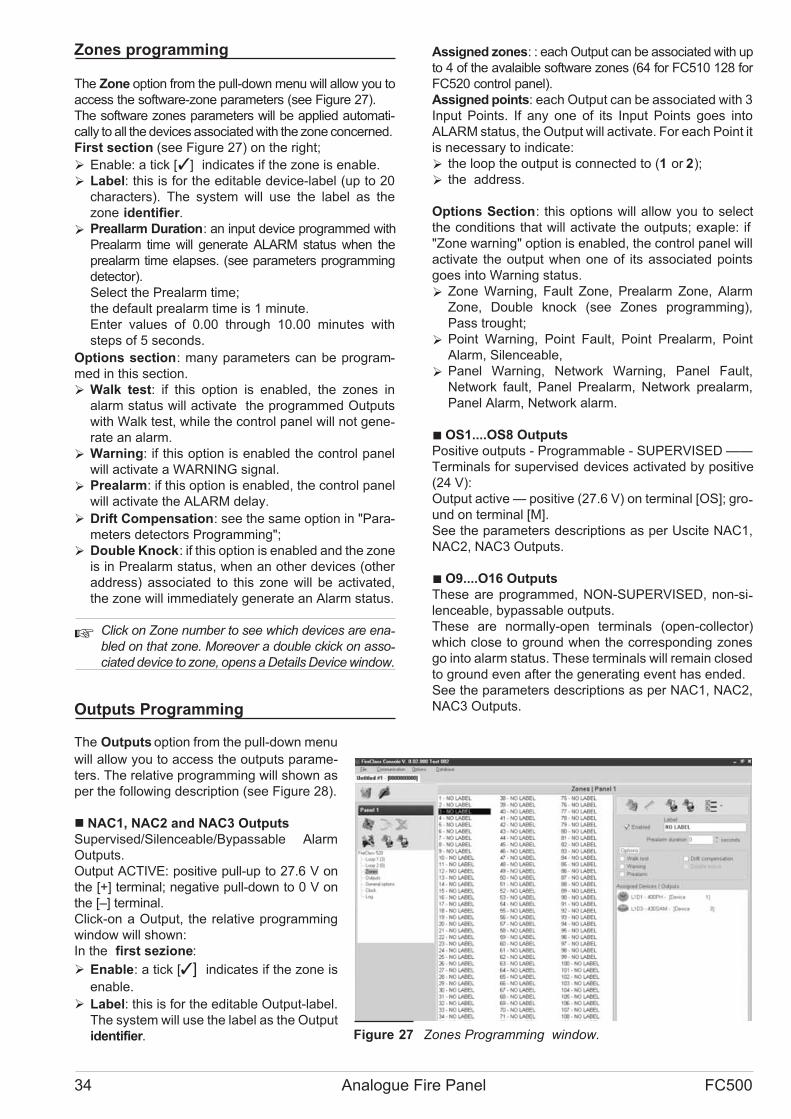
Zones programming
The Zone option from the pull-down menu will allow you to
access the software-zone parameters (see Figure 27).
The software zones parameters will be applied automati-
cally to all the devices associated with the zone concerned.
First section (see Figure 27) on the right;
� Enable: a tick [�] indicates if the zone is enable.
� Label: this is for the editable device-label (up to 20
characters). The system will use the label as the
zone identifier.
� Preallarm Duration: an input device programmed with
Prealarm time will generate ALARM status when the
prealarm time elapses. (see parameters programming
detector).
Select the Prealarm time;
the default prealarm time is 1 minute.
Enter values of 0.00 through 10.00 minutes with
steps of 5 seconds.
Options section: many parameters can be program-
med in this section.
� Walk test: if this option is enabled, the zones in
alarm status will activate the programmed Outputs
with Walk test, while the control panel will not gene-rate an alarm.
� Warning: if this option is enabled the control panel
will activate a WARNING signal.
� Prealarm: if this option is enabled, the control panel
will activate the ALARM delay.
� Drift Compensation: see the same option in "Para-
meters detectors Programming";
� Double Knock: if this option is enabled and the zone
is in Prealarm status, when an other devices (other
address) associated to this zone will be activated,
the zone will immediately generate an Alarm status.
� Click on Zone number to see which devices are ena-bled on that zone. Moreover a double ckick on asso-ciated device to zone, opens a Details Device window.
Outputs Programming
The Outputs option from the pull-down menu
will allow you to access the outputs parame-
ters. The relative programming will shown as
per the following description (see Figure 28).
� NAC1, NAC2 and NAC3 Outputs
Supervised/Silenceable/Bypassable Alarm
Outputs.
Output ACTIVE: positive pull-up to 27.6 V on
the [+] terminal; negative pull-down to 0 V on
the [–] terminal.
Click-on a Output, the relative programming
window will shown:
In the first sezione:
� Enable: a tick [�] indicates if the zone is
enable.
� Label: this is for the editable Output-label.
The system will use the label as the Output
identifier.
Assigned zones: : each Output can be associated with up
to 4 of the avalaible software zones (64 for FC510 128 for
FC520 control panel).
Assigned points: each Output can be associated with 3
Input Points. If any one of its Input Points goes into
ALARM status, the Output will activate. For each Point it
is necessary to indicate:
� the loop the output is connected to (1 or 2);
� the address.
Options Section: this options will allow you to select
the conditions that will activate the outputs; exaple: if
"Zone warning" option is enabled, the control panel will
activate the output when one of its associated points
goes into Warning status.
� Zone Warning, Fault Zone, Prealarm Zone, Alarm
Zone, Double knock (see Zones programming),
Pass trought;
� Point Warning, Point Fault, Point Prealarm, Point
Alarm, Silenceable,
� Panel Warning, Network Warning, Panel Fault,
Network fault, Panel Prealarm, Network prealarm,
Panel Alarm, Network alarm.
� OS1....OS8 Outputs
Positive outputs - Programmable - SUPERVISED ——
Terminals for supervised devices activated by positive
(24 V):
Output active — positive (27.6 V) on terminal [OS]; gro-und on terminal [M].
See the parameters descriptions as per Uscite NAC1,
NAC2, NAC3 Outputs.
� O9....O16 Outputs
These are programmed, NON-SUPERVISED, non-si-lenceable, bypassable outputs.
These are normally-open terminals (open-collector)
which close to ground when the corresponding zones
go into alarm status. These terminals will remain closed
to ground even after the generating event has ended.
See the parameters descriptions as per NAC1, NAC2,
NAC3 Outputs.
34 Analogue Fire Panel FC500
Figure 27 Zones Programming window.
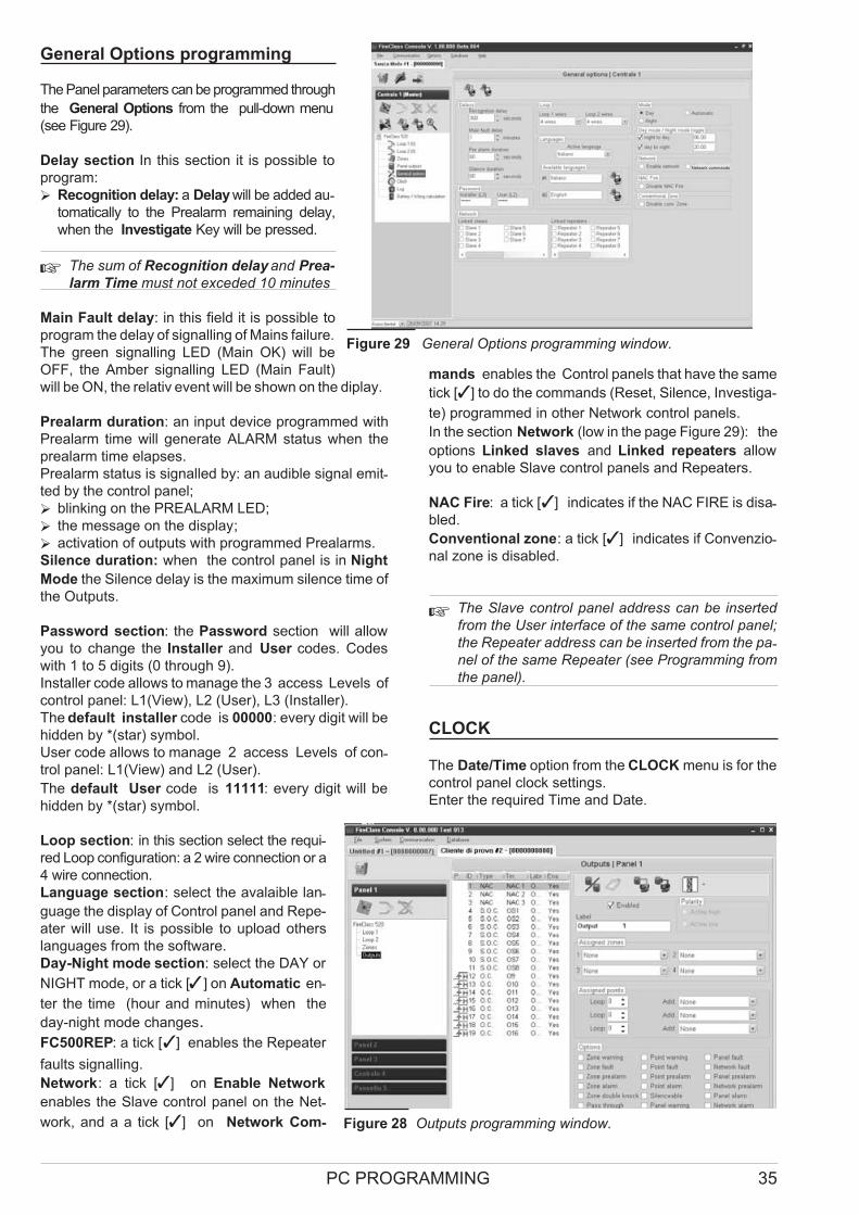
General Options programming
The Panel parameters can be programmed through
the General Options from the pull-down menu
(see Figure 29).
Delay section In this section it is possible to
program:
� Recognition delay: a Delay will be added au-tomatically to the Prealarm remaining delay,
when the Investigate Key will be pressed.
� The sum of Recognition delay and Prea-
larm Time must not exceded 10 minutes
Main Fault delay: in this field it is possible to
program the delay of signalling of Mains failure.
The green signalling LED (Main OK) will be
OFF, the Amber signalling LED (Main Fault)
will be ON, the relativ event will be shown on the diplay.
Prealarm duration: an input device programmed with
Prealarm time will generate ALARM status when the
prealarm time elapses.
Prealarm status is signalled by: an audible signal emit-ted by the control panel;
� blinking on the PREALARM LED;
� the message on the display;
� activation of outputs with programmed Prealarms.
Silence duration: when the control panel is in Night
Mode the Silence delay is the maximum silence time of
the Outputs.
Password section: the Password section will allow
you to change the Installer and User codes. Codes
with 1 to 5 digits (0 through 9).
Installer code allows to manage the 3 access Levels of
control panel: L1(View), L2 (User), L3 (Installer).
The default installer code is 00000: every digit will be
hidden by *(star) symbol.
User code allows to manage 2 access Levels of con-trol panel: L1(View) and L2 (User).
The default User code is 11111: every digit will be
hidden by *(star) symbol.
Loop section: in this section select the requi-red Loop configuration: a 2 wire connection or a
4 wire connection.
Language section: select the avalaible lan-
guage the display of Control panel and Repe-
ater will use. It is possible to upload others
languages from the software.
Day-Night mode section: select the DAY or
NIGHT mode, or a tick [�] on Automatic en-
ter the time (hour and minutes) when the
day-night mode changes.FC500REP: a tick [�] enables the Repeater
faults signalling.
Network: a tick [�] on Enable Network
enables the Slave control panel on the Net-
work, and a a tick [�] on Network Com-
mands enables the Control panels that have the same
tick [�] to do the commands (Reset, Silence, Investiga-
te) programmed in other Network control panels.
In the section Network (low in the page Figure 29): the
options Linked slaves and Linked repeaters allow
you to enable Slave control panels and Repeaters.
NAC Fire: a tick [�] indicates if the NAC FIRE is disa-bled.
Conventional zone: a tick [�] indicates if Convenzio-nal zone is disabled.
� The Slave control panel address can be inserted
from the User interface of the same control panel;
the Repeater address can be inserted from the pa-nel of the same Repeater (see Programming from
the panel).
CLOCK
The Date/Time option from the CLOCK menu is for the
control panel clock settings.
Enter the required Time and Date.
PC PROGRAMMING 35
Figure 28 Outputs programming window.
Network commands
Figure 29 General Options programming window.

LOG
This option allows to read the Log stores
events.
When a Customer will be closed, the system
save automatically the present LOG. In this
way the LOG is always updated.
Description of the icons in the LOG bar:
Up load from Board: click-on this icon to
upload the LOG of the connected control panel.
Export LOG to file: click-on this icon to ex-port the LOG in a .fcl file.
Import LOG from file: click-on this icon to
import the LOG from a .fcl file.
Apply filter: click-on this icon to select the
LOG filter (if necessary):
� No filter
� Restore
� Alarm
� Prealarm
� Warning
� Fault
� Generic
� Walk test
Filter: click-on this icon to select others LOG filter (if
necessary):
� Filter by panel
� Filter by Loop
� Filter by device
� Filter by zone.
The following data will be stored in the LOG:
the Event's Number, the Date, the Time, the Class
(Fault, Alarm, Warning, Generic and Walk test), the
Event's description, the Control panel number, the
Loop, the Device type, the Status, the Threshold and
the Zone.
Battery Calculation
The Battery calculation window allows you to
see (Figure 31):
� the FireClass500 Loads
� the Loop1,Loop 2 devices loads
in the condition of Normal Load and Alarm
Loads (percentage of devices in alarm status),
when the Mains faults.
Below this window, in the option "Others Load",
if needed, the Loads on Auxliary terminals will
be inserted. Automatically the Total Load and
the Battery needed will be shown.
Fixed the Stand-by hours, Alarm minutes
and Alarm percentage values the calculation
will be done.
Battery calculation Parameters:
� Stand-by hours (From 1 to 144 h)
� Alarm minutes (From 1 to 240 h)
� Alarm percentage
Battery Type: this is the battery (Ah) arising from calcu-
lation.
Battery calculation constraints:
� Lock stand-by hours
� Lock battery type.
Lock stand-by hours: "Battery Type" value (Ah) will be
calculate, fixed Stand-by hours, Alarm minutes and
Alarm percentage ;
Lock battery type: "Stand-by hours" value will be cal-
culate, fixed Battery Type (Ah), Alarm minutes and
Alarm percentage.
� The software calculation is a rough calcolation and
cannot substitute the Installer and/or Qualified per-son calculation.
36 Analogue Fire Panel FC500
Figure 30 Create/modify language window
Figure 31 Battery calculation window

Loop Wiring calculation
In the same Battery Calculation window (see
Figure 31), on the right, FireClass500 Console
allows you the Loop Wiring Calculation.
After the Loop devices have been program-
med, clicking on Loop1 or Loop 2 field (Installa-
tion Loop), the Loop Wiring Calculation
window will open. Insert the wire type in the
Max wire Resistance field (value in Ohm/Km);
automatically, the max Loop length will be
shown in the Loop Length field (value in m.) .
Vice versa, inserted the Loop Length, auto-
matically, the Max wire Resistance (Wire
type) will be shown.
Clicking on this Icon the Wire database
will be open. In this database it is possible to in-sert many type of wires and so these type of wires will
be used in the Loop wire calculation.
LangBuilder
The LangBuilder application will allow you to customize a
language:
� the terminology used in the Fire Software suite appli-
cations is called the Software strings;
� the Templates used on the FC500 control panel di-splay, and Repeater panel display is called LCD pa-ges;
� the terminology used on the FC500 control panel di-
splay, and Repeater panel display is called LCD
strings1 and LCD strings2.
� The source language of the LangBuilder applica-tion is English.
� Create/Modify language
To create/modify language work carefully through
the following steps:
1- In the LangBuilder main window (see Figure 33)
insert the name of new language to create in the
field "Language name", than press the "Next"
key.
2- In the following window (see Figure 30), insert
the translations in the "English string" field into
"Current string" field. Under this field the descrip-tion of the term to translate is shown. The new
translated word will be inserted in the "New
string" field. You can use 28 characthers for every
new translation.
3-Use UP or DOWN arrows to select the terms to
translate. You can also use the Goto field: select
the number corresponding to the word to translate.
4-After the new translated words (new language) have
been inserted, press the "LCD Strings Language" or
the "Next" key to translate the LCD strings.
The window in figure 32 will be shown.
5-Insert the new translated Strings in the "Current LCD
string" field.
It is possible to modify the LCD part white coloured
ONLY, while that one pink coloured cannot be modified.
In this way you can obtain all the "LCD pages", than
press the "Next" key.
6- See figure 32, in this windows you can translate the
"LCD Strings".
7-At the end, press "Save" key to save the new
language; confirm before continuing.
PC PROGRAMMING 37
Figure 32 LCD strings window
Figure 33 LangBuilder main window

38 Analogue Fire Panel FC500
(L2)
L1, L2 and L3 leveloperationsDefault Installer code 00000: PROGRAM DISABLE
910 910 910 910 910
DISABLEZONE
DISABLETELECOM
DISABLEOUTPUTS
DISABLENETWORKDEVICE
DISABLEDEVICE
440 440 440 440
SELECTA ZONE
SELECTTHE OUTPUT
SELECT THENETWORKDEVICE
SELECTA DEVICE IN
CONFIGURATION
432
431
430SELECT THE
CONTROL PANEL
SELECTTHE LOOP
200200
323
LIST ZONE TELECOM OUTPUTS NETWORK LOOP 1..8
20
WRONGTRY A
I
USER PWDREQUEST
WRONG PWDTRY AGAIN
SELECT WHATTO DISABLE
IN
SELECT THECONTROL PANEL
430
STARTINGSYSTEM
(L3)200 200
LOOP 1..8
310
ZONE SYSTEM TELECOM OPTIONS FACTORYDEFAULT
AUTOSCAN
312
WARNINGFOUND
DIFFERENCES
312SHOW
RESULTS
314
440
SCEGLIL’USCITA
440 440
430
431
432
800 800 800 800 800 800 800 800
PROGRAMNETWORKDEVICE
PROGRAMOUTPUT
PARAMETERS
LABEL
NETWORKADDRESS
PROGRAMDEVICES
PARAMETERS
ASSOCIATEDZONE
TYPE
LABEL
TYPEPROCESSING
TIMERS
DRIFTCOMPENSATION
ALARMVERIFY
PROGRAMZONE
PARAMETERS
PROGRAMSYSTEM
PARAMETERS
PROGRAMTELECOM
PARAMETERS
PROGRAMOPTIONS
FACTORYDEFAULT,PROGRAM
MAINTENANCE
440
AUTO-LEARNING
WRONG PWDTRY AGAIN
SELECT WHATTO PROGRAM
INSTALLER PWDREQUEST
OUTPUTS NETWORK
SHOWRESULTS
SELECTA ZONE
SELECTTHE TELECOM
INTERFACE
SELECTTHE TELECOM
INTERFACE
SELECT THECONTROL PANEL
SELECTTHE LOOP
SELECTA DEVICE
SELECT THENETWORKDEVICE
ALARMTHRESHOLDS
SELECT THECONTROL PANEL
SELECT THECONTROL PANEL
Figure 34 Diagram of all possible operations from the panel, L1, L2 and L3 Levels (some operation is not available).

PC PROGRAMMING 39
(L1)
(L1)
(L2)
(L1)
(L2)
= L1 Access Level
= L2 Access Level
MAIN PAGE
MODIFYPARAMETHERS
READINGLOG
READINGDISABLED
LIST
100
00 200
G PWDGAIN
USER PWDREQUEST
SELECT WHATTO MODIFY
320
INIT. MESSAGE SETL2 PASSWORD
DELETEVERIFY
DELETELOG
TELECOMINTERFACE
PARAMETHERMODIFY
800 800 800200
SETPASSWORD
330
LOOP
430 430
DEVICE NETWORK ZONES
SELECT THECONTROL PANEL
431
SELECT THELOOP
432 440420
OUTPUTS OPTIONS LOG PRINT TELECOMINTERFACE
4B0
FW VERSION
PAGEWITH
FW VERSION
314 A20 A30 A50A40 A60 A70
410
SCROLL ANDVIEW THE LOOPS
VIEW THEDEVICE
VIEW THENETWORKDEVICE
VIEW THEZONE
VIEW THEOUTPUT
SELECT WHATTO VIEW
SETNIT. MESSAGE
SETDELETE VERIFY
SELECT THECONTROL PANEL
SELECTA DEVICE IN
CONFIGURATION
SELECT THENETWORKDEVICE
SELECTA ZONE
SELECTTHE OUTPUT
SCROLL ANDVIEW THEOPTIONS
SCROLL ANDVIEW THEEVENTS
A71 A71 A71 A71
DISABLED ZONESDISABLEDDEVICES
DISABLEDFUNCTIONS
WALK TESTZONES
WARNINGSLIST
VIEW and SCROLLDISABLED ZONES
F00
ALARM
F01
PREALARM
F02
FAULT
F03
WARNING
F05
WALK TEST
PAGES AREDIRECTLY ACTIVATEDBY EVENTS
VIEW LISTS
340
(L1)
START PAGE
005
VIEW and SCROLLDISABLEDDEVICES
VIEW and SCROLLDISABLEDFUNCTIONS
VIEW and SCROLLDISABLED ZONES
(L3) = L3 Access Level
PROGRAMMING FROM THE PANEL
Read through the following section carefully, in order to
get an overall view of how to use the User interface Pro-gramming (Main panel) of control panel.
For details regarding the parameters of each phase, re-fer to the respective paragraph in the
“PROGRAMMING FROM A PC” chapter.
Using the system
The FC500 system can be managed from the User in-terface (main panel) and/or through the FireClass500
Console application (the computer must be connected
locally via RS232 serial port). The User interface (main
panel) allows access to different Level authorized.
There are three different access levels, as follows.
L1= First Level: this level allows the Reading Parame-
ters ONLY:
LOOP, DEVICES, LOG.
L2= Second Level or USER Level: access to this level
requires entry of the USER PIN (Access Level 2). This
level allows all the operations of the First Level, moreo-
ver allows to MODIFY:
THE USER PASSWORD, CLEAR LOGGER; or allows:
to DISABLE the control panel peripherals and delete
(clear) the Log.
L3= Third Level or INSTALLER Level: access to this
level requires entry of the INSTALLER PIN (Access Le-
vel 3). This level allows all the operations of the First
and Second Level, moreover allows to program the se-
curity system; the Programming phase allows the in-staller to program the control panel and peripheral
devices (detectors, modules, repeater and slave pa-nels), in details:
AUTO, NETWORK, DEFAULT, L3 PWD;
the following options must be defined: OUTPUTS,
LOOP1..8, ZONES, SYSTEM, TELECOM
INTERFACE, OPTIONS.
� Operating the system
To manage the system from the User interface (Main
panel) is used the Alphanumeric keypad, the Cursor
keys, the ESC Key , the ENTER key and the
Functions Keys F1 ,F2 , F3 and F4 .
� In detail the use of Alphanumeric keypad, the Cursor
keys, the ESC Key , the ENTER key and the Fun-
ctions Keys F1, F2, F3 and F4 is shown in every page
of PROGRAMMING/DISABLE/MODIFY/READING
PARAMETERS.
Editing a text Use the Alphanumeric keypad to create
labels and enter data and codes.
Use LEFT and RIGHT keys to scroll along the
line, then press the alphanumeric key to insert in the se-lected position.
Use the UP key for upper-case letters and the
DOWN key for lower-case letters.
Once the text has been completed, press the ENTER
key to confirm and step forward, or position the cur-
sor on the first letter of the text then press the key to
step back
The Zero key allows to insert some punctuation marks,
(full stop, comma and hyphen) and the blank (Future
Use).
� In the following pages are shown all possible ope-rations managed at Level 3 ( Installer Level).
The operation managed at Level L1 and L2 (User
Level) are shown in the User Manual.
40 Analogue Fire Panel FC500
ESC
F1 F2 F3 F4
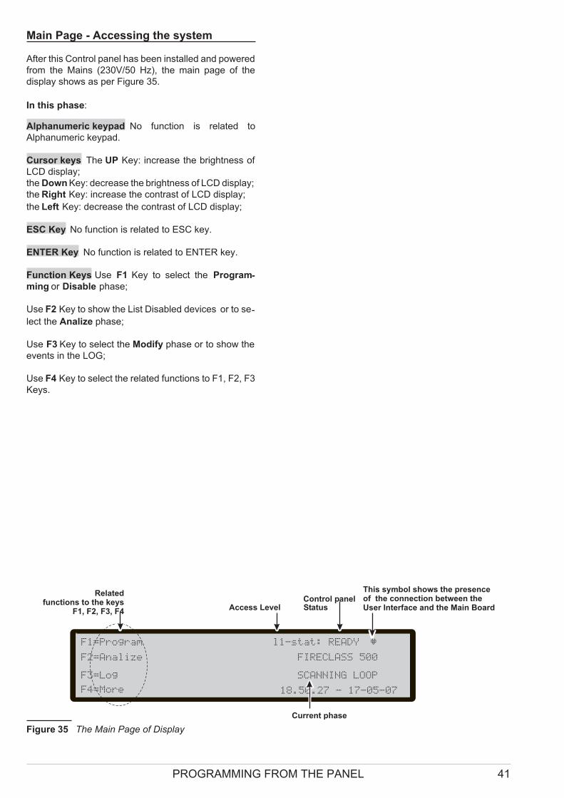
Main Page - Accessing the system
After this Control panel has been installed and powered
from the Mains (230V/50 Hz), the main page of the
display shows as per Figure 35.
In this phase:
Alphanumeric keypad No function is related to
Alphanumeric keypad.
Cursor keys The UP Key: increase the brightness of
LCD display;
the Down Key: decrease the brightness of LCD display;
the Right Key: increase the contrast of LCD display;
the Left Key: decrease the contrast of LCD display;
ESC Key No function is related to ESC key.
ENTER Key No function is related to ENTER key.
Function Keys Use F1 Key to select the Program-ming or Disable phase;
Use F2 Key to show the List Disabled devices or to se-
lect the Analize phase;
Use F3 Key to select the Modify phase or to show the
events in the LOG;
Use F4 Key to select the related functions to F1, F2, F3
Keys.
PROGRAMMING FROM THE PANEL 41
F1=Program l1-stat: READY
F2=Analize FIRECLASS 500
F3=Log SCANNING LOOP
F4=More
Relatedfunctions to the keys
F1, F2, F3, F4Access Level
This symbol shows the presenceof the connection between theUser Interface and the Main Board
Current phase
Control panelStatus
18.50.27 - 17-05-07
Figure 35 The Main Page of Display
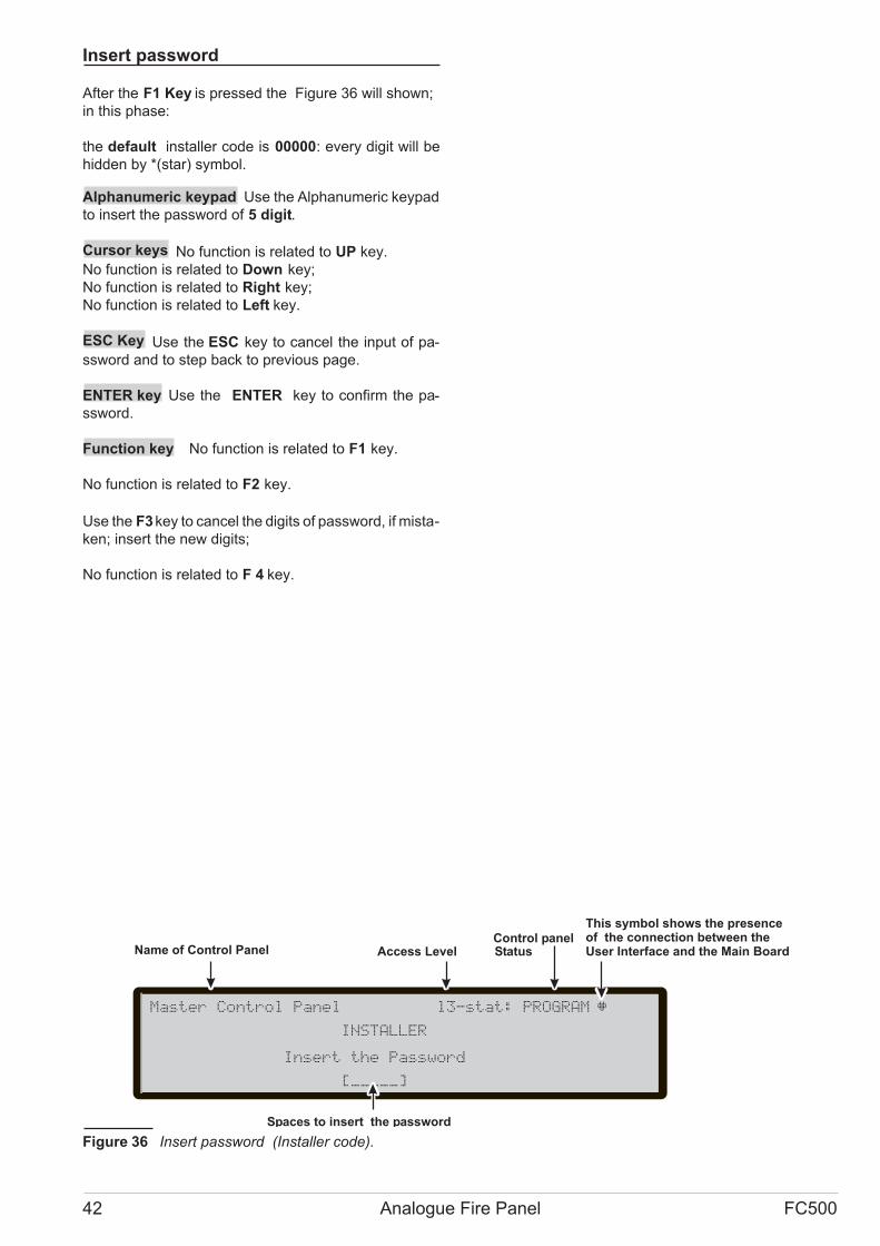
Insert password
After the F1 Key is pressed the Figure 36 will shown;
in this phase:
the default installer code is 00000: every digit will be
hidden by *(star) symbol.
Alphanumeric keypad Use the Alphanumeric keypad
to insert the password of 5 digit.
Cursor keys No function is related to UP key.
No function is related to Down key;
No function is related to Right key;
No function is related to Left key.
ESC Key Use the ESC key to cancel the input of pa-
ssword and to step back to previous page.
ENTER key Use the ENTER key to confirm the pa-
ssword.
Function key No function is related to F1 key.
No function is related to F2 key.
Use the F3key to cancel the digits of password, if mista-
ken; insert the new digits;
No function is related to F 4 key.
42 Analogue Fire Panel FC500
Master Control Panel l3-stat: PROGRAM
INSTALLER
Insert the Password
[____ ]_
Name of Control Panel
Spaces to insert the password
This symbol shows the presenceof the connection between theUser Interface and the Main Board
Control panelStatusAccess Level
Figure 36 Insert password (Installer code).

Programming Page
From Main page, use the F1 Key to select the Program-
ming phase. Insert the password (installer code) and
then the page is shown in Figure 37 :
in this phase:
Alphanumeric keypad Use the Alphanumeric keypad
to select the different programming functions:
1= Auto: start the auto-learning of the loop devices and the
RS485 network devices automatically;
0= L3 PWD; start the page to insert the password of L3 le-
vel (Installer code) (see Insert-Modify password page);
5= Network: start the programming page of the RS485
network devices
� The following options must be defined.
2= FC Dev: start the selection and programming
page of the loop devices;
3= SW Zones: start the programming page of the
software zones;
4=Outputs: start the programming page of the
Outputs;
6= Telecom: start the programming page of the te-lecomunication devices;
7=Options: start the programming page of the op-tions;
8=System: start the programming page of the
system parameters;
Cursor keys No function is related to UP key.
No function is related to Down key;
No function is related to Right key;
No function is related to Left key.
ESC Key Use ESC key to cancel the operation and to
step back to previous page.
ENTER Key No function is related to ENTER key
Function Key No function is related to F1 key;
No function is related to F2 key;
No function is related to F3 key;
No function is related to F4 key.
PROGRAMMING FROM THE PANEL 43
Master Control panel l3-stat: PROGRAM
1=Auto 2=FC dev. 3=SW zone 4=Output
5=Network 6=Telecom 7=Options 8=System
9=Default 0=L3 PWD
Options
Name of Control Panel
This symbol shows the presenceof the connection between theUser Interface and the Main Board
Control panelStatusAccess Level
Figure 37 Main programming page
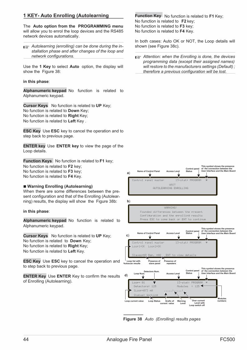
1 KEY- Auto Enrolling (Autolearning
The Auto option from the PROGRAMMING menu
will allow you to enrol the loop devices and the RS485
network devices automatically.
� Autolearning (enrolling) can be done during the in-stallation phase and after changes of the loop and
network configurations.
Use the 1 Key to select Auto option, the display will
show the Figure 38:
in this phase:
Alphanumeric keypad No function is related to
Alphanumeric keypad.
Cursor Keys No function is related to UP Key;
No function is related to Down Key;
No function is related to Right Key;
No function is related to Left Key .
ESC Key Use ESC key to cancel the operation and to
step back to previous page.
ENTER key Use ENTER key to view the page of the
Loop details.
Function Keys No function is related to F1 key;
No function is related to F2 key;
No function is related to F3 key;
No function is related to F4 Key.
�Warning Enrolling (Autolearning)
When there are some differences between the pre-sent configuration and that of the Enrolling (Autolear-ning) results, the display will show the Figure 38b:
in this phase:
Alphanumeric keypad No function is related to
Alphanumeric keypad.
Cursor Keys No function is related to UP Key;
No function is related to Down Key;
No function is related to Right Key;
No function is related to Left Key.
ESC Key Use ESC key to cancel the operation and
to step back to previous page.
ENTER Key Use ENTER Key to confirm the results
of Enrolling (Autolearning).
Function Key No function is related to F1 Key;
No function is related to F2 key;
No function is related to F3 key;
No function is related to F4 Key.
In both cases: Auto OK or NOT, the Loop details will
shown (see Figure 38c).
� Attention: when the Enrolling is done, the devices
programming data (except their assigned names)
will restore to the manufacturers settings (Default) ;
therefore a previous configuration will be lost.
44 Analogue Fire Panel FC500
Control panel master l3-stat: PROGRAM
Slaves=NO Rep. =NO ENT to view details
Loop list withAutoscan results
Presence ofslave panel
Loop1=OK Loop2=OK
Presence ofrepeaters
WARNING!
Founded differences between the present
a)
b)
Configuration and the enrolling results
Press ESC to come back or ENT to continue
Loop= 01 l3-stat: PROGRAM
Modules : 125
Status: Working
Loop Num.
ILoop=073 mA .....|.....|
Loop current value Loop Status Grafic ofcurrent value
Detectors: 125
Detectors Num.
c)
ModulesnumbersWarning
Level
Over currentLevel with
Loop switch off
Name of Control Panel
This symbol shows the presenceof the connection between theUser Interface and the Main Board
Control panelStatusAccess Level
This symbol shows the presenceof the connection between theUser Interface and the Main Board
Control panel
StatusAccess Level
WAIT
d)
Control panel master l3-stat: PROGRAM
Name of Control Panel
This symbol shows the presenceof the connection between theUser Interface and the Main Board
Control panel
StatusAccess Level
AUTOLEARNING ENROLLING
Figure 38 Auto (Enrolling) results pages

0 KEY - insert-Modify password
In this phase (see figure 39):
Installer Code at Default is 00000; every digit will be
masked by * symbol.
Alphanumeric keypad Use the Alphanumeric keypad
to insert the password of 5 digit.
Cursor keys No function is related to UP key.
No function is related to Down key;
No function is related to Right key;
No function is related to Left key.
ESC Key Use the ESC key to cancel the input of pa-ssword and to step back to previous page.
ENTER key Use the ENTER key to confirm the pa-ssword.
Function key No function is related to F1 key.
No function is related to F2 key.
Use theF3 key to cancel the digits of password, if mista-ken; insert the new digits;
No function is related to F4.
9 KEY- Restore Default
The Restore Default option from the PROGRAMMING
menu will allow you to restore default setting.
Use the 9 Key to select Restore Default, the display
will show the Figure 40:
in this phase:
Alphanumeric keypad No function is related to
Alphanumeric keypad.
Cursor Keys No function is related to UP Key;
No function is related to Down Key;
No function is related to Right Key;
No function is related to Left Key .
ESC Key No function is related ESC key.
ENTER key No function is related ENTER Key.
Function Keys No function is related to F1 key;
No function is related to F2 key;
No function is related to F3 key;
No function is related to F4 Key.
PROGRAMMING FROM THE PANEL 45
Master Control Panel l3-stat: PROGRAM
INSTALLER
Insert the NEW Password
[____ ]_
Name of Control Panel
Spaces to insert the password
This symbol shows the presenceof the connection between theUser Interface and the Main Board
Control panelStatusAccess Level
Figure 39 Insert-Modify password (Installer code).
DEFAULT data loading in progress
The system will restart
WARNING
Figure 40 Restore default page

5 Key- Network
At default, every FC500 Control panel is a Master Con-trol Panel disabled in the Network.
� If a control panel is already configured as "Master",
verify, via PC, if it is enabled in the Network.
If a control panel is already configured as "Slave",
in the new installation, insert the Slave address
from the user interface of the Contro panel itself.
In the Network ONLY one Master control panel
must be present.
When all the Control panels and the Repeaters are con-nected in the Network, the system can be supplied.
Now it is necessary to configure the Network, so work
through the following steps:
1- use the 5 Key to select Network, from Programming
page (Figure 37) in the User interface of the control pa-nel to be configured;
2- the Display of Figure 41 will be shown;
3- use the cursor keys to select the type of control panel
assigned as "Slave" (address);
4- use the Enter key to confirm.
� Every "Slave" control panel inserted in the Network
must have a different address.
Alphanumeric keypad No function is related to
Alphanumeric keypad;
Cursor Keys No function is related to UP Key;
No function is related to Down Key;
Use the DX key to move on the Right to select the type
of the control panel.
Use the SX key to move on the Left to select the type of
the control panel.
ESC Key Use ESC key to cancel the operation and to
step back to previous page.
ENTER Key Use the ENTER Key to confirm the ad-
dress.
Function Keys No function is related to F1 key;
No function is related to F2 key;
No function is related to F3 key;
No function is related to F4 Key.
46 Analogue Fire Panel FC500
Network l3-stat : PROGRAM
PANEL TYPE MASTER PANEL
Ms s1 s2 s3 s4 s5 s6
^
Livello di accesso
Indica la presenza delcollegamento tra interfacciautente e la scheda madre.
Simbolo per selezionare la centrale da configurare come slave
Stato della centrale
Figure 41 Display to enable (address) the FC500 Slave Control Panel.

FC500REP Repeater Addressfrom the Repeater panel ONLY
After the FC500 control panel has been connected, at
the first start-up the FC500REP will verify the presence
of the address and its conformity. If the address is cor-rect, the Repeater will start to work; on the contrary
the display will ask to insert a new address; the display
of Figure 42 will be shown; in this phase:
Alphanumeric keypad Use the alphanumeric keypad
to insert the address of 1 digit.
Cursor Keys No function is related to UP Key;
No function is related to Down Key;
No function is related to Right Key;
No function is related to Left Key.
ESC Key Use ESC key to cancel the operation and to
step back to previous page.
Tasto ENTER Use the ENTER Key to confirm the ad-
dress.
Function Keys No function is related to F1 key;
No function is related to F2 key;
No function is related to F3 key;
No function is related to F4 Key.
� If for any reason the address of a repeater is chan-
ged by mistake, the system will show the message
of the Figure 43, in this case the address of the re-
peater will be changed using the ESC key.
NETWORK Configuration
Two ways are available to enrol the Network:
first:
1- the Master Control panel can do the Enrolling (autolear-ning) after one or more Slave Control panels and one or
more Repeaters have been enabled in the network (see
previous paragraphs);
1a- use the 1 Key to enroll (see page 44);
1b- use the "Upload from board" key (Software FireClass500
console) in the Master control panel;
second:
2- Use the Software (FireClass500 console) to insert one
or more Slave Control panels (from Master control panel);
2a- Use the "General Options" section (FireClass500 con-
sole) in every Slave control panels to enable the Slave pa-
nel in the network;
2b- Use the "General Options" section (FireClass500
console) in the Master control Panel to enable the Slave
Control panels, the Repeaters and the Master control pa-nel itself in the network .
2c- Use the " Download to board" key.
After the "Auto" Enrolling the system configure the Net-work devices (Slave control panels and Repeaters) and
besides the Loop devices.
At the end of the "Auto" Enrolling, the "Master" control
panel can manage the "Slave" control panels and the
Repeaters.
PROGRAMMING FROM THE PANEL 47
FC500REP REPEATER
Insert the number of the address [1-8]
[_]
Space to insert the address
This symbol shows the presenceof the connection between theFC500REP repeater the MasterControl Panel and the relativeaddress.
Figure 42 Display to insert a new FC500REP address.
!!FAULT!!Serial link is down
unable to communicate with the system
press ESC to change repeater address
Figure 43 Display "the repeater link is down"

QUICK START-UP PROCEDURE
These procedure allows the quick start-up of the
FC510/520 fire detection system.
When the loops are wired, electrically verified and all
the devices have been programmed with their related
address and installed to the loop, it is possible to con-
nect the loops terminals to the panel.
� Before powering-on the Fire control panel, ensure
that the Earth Line has been connected.
PROCEDURE:
1. Power-on the panel
2. Insert the data and time , if requested ( this step it is
important to guarantee the Log file consistency).
At this point the panel will start the first system initializa-tion verifying the loops integrity, warming up the smoke
sensor circuitry, looking for not address programmed
devices over the loops and searching devices with the
same address.
� NOTE: The panel in this phase is configured to ma-nage closed loops (4 wires loop), if it is connected
to a spur (2 wires loop) will be generate broken
loop faults.
At the end of this first initialization phase will be activa-
ted on the user interface the main page with the capabi-
lity to accede to the command and control functions
3. Select the function Program pressing the key F1
4. Insert the installer password (default=00000) every
digit will be masked by * symbol.
5. Choose the option Auto pressing the key 1
The panel will start the enrolling procedure. At the end
of this phase will be presented the result of the enrolling
in terms of loop with devices connected (OK) or not
(KO) and it will be possible view the details for each acti-
ve loop (number of detectors, number of modules, cur-
rent drawn), pressing the key [ESC] it is possible to
reach again the main page.
� If the enrolling result differ from the previously sto-red loop configuration a warning message will be
displayed and it is possible to reject the present en-rolling result ,maintaining the previous configura-tion, or accept them.Suddenly after the enrolling
phase the panel starts the loops initialization pha-se.
At the end of this phase, which duration is related to the
number and type of the devices connected over the lo-
ops, the panel it is able to act according the directive of
the EN54-2 standard.
� The enrolling function will not be activated if there
are present loop related faults.
The functional parameters of the panel and devices at
the end of the enrolling procedure are listed below
� Detectors
FC400H: A2S mode
FC400P: standard mode, medium sensitivity
FC400PH: (temp. = A2S) + (Smoke = standard
mode, medium sensitivity).
� All detectors activation will generate panel ALARM
�Modules
FC410MIM: input style=C,NO
FC410SIO: input style=C,NO,
output NOT active
FC410MIO: inputs style=C,NO
outputs NOT active
FC420CP: Call-point fully active
FC430SAB : NOT active
FC430SAM: NOT active
� All modules activation will generate panel ALARM
48 Analogue Fire Panel FC500
� Zones
No zone active
� Panel outputs
“NAC FIRE” (output EN54-2 type C) active on alarm
event
“FIRE” (dry contact) active on alarm event
“FAULT” (dry contact) active on fault event
� Conventional zone
Active,
pre-alarm on detector activation (680 � load),
alarm on call-point activation (270 � load),
� Panel general option
Pre-alarm time: 60s
Investigation time: 300s
Silence time: 30s
Mains fault delay: 1min
Day mode
Loop configuration: 4 wires
QUICK START-UP PROCEDURE 49
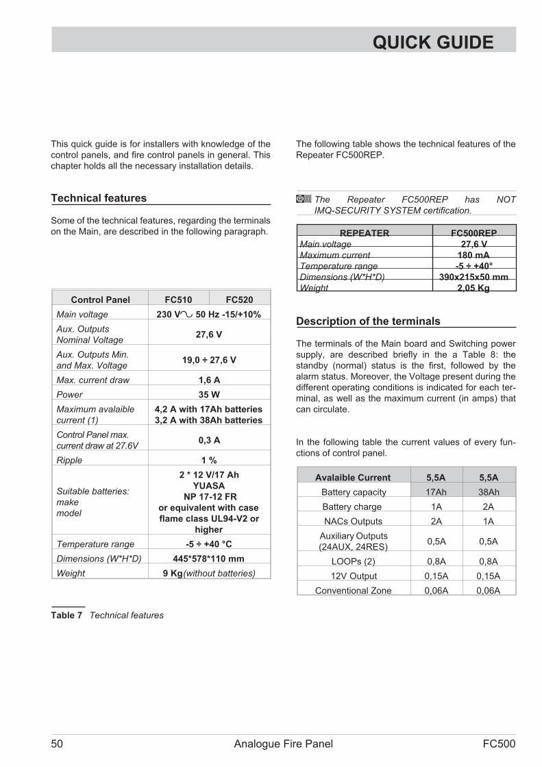
QUICK GUIDE
This quick guide is for installers with knowledge of the
control panels, and fire control panels in general. This
chapter holds all the necessary installation details.
Technical features
Some of the technical features, regarding the terminals
on the Main, are described in the following paragraph.
The following table shows the technical features of the
Repeater FC500REP.
A The Repeater FC500REP has NOT
IMQ-SECURITY SYSTEM certification.
REPEATER FC500REP
Main voltage 27,6 V
Maximum current 180 mA
Temperature range -5 ÷ +40°
Dimensions (W*H*D) 390x215x50 mm
Weight 2,05 Kg
Description of the terminals
The terminals of the Main board and Switching power
supply, are described briefly in the a Table 8: the
standby (normal) status is the first, followed by the
alarm status. Moreover, the Voltage present during the
different operating conditions is indicated for each ter-minal, as well as the maximum current (in amps) that
can circulate.
In the following table the current values of every fun-ctions of control panel.
Avalaible Current 5,5A 5,5A
Battery capacity 17Ah 38Ah
Battery charge 1A 2A
NACs Outputs 2A 1A
Auxiliary Outputs
(24AUX, 24RES)0,5A 0,5A
LOOPs (2) 0,8A 0,8A
12V Output 0,15A 0,15A
Conventional Zone 0,06A 0,06A
50 Analogue Fire Panel FC500
Control Panel FC510 FC520
Main voltage 230 V~ 50 Hz -15/+10%
Aux. Outputs
Nominal Voltage27,6 V
Aux. Outputs Min.
and Max. Voltage19,0 ÷ 27,6 V
Max. current draw 1,6 A
Power 35 W
Maximum avalaible
current (1)
4,2 A with 17Ah batteries
3,2 A with 38Ah batteries
Control Panel max.
current draw at 27.6V0,3 A
Ripple 1 %
Suitable batteries:
make
model
2 * 12 V/17 Ah
YUASA
NP 17-12 FR
or equivalent with case
flame class UL94-V2 or
higher
Temperature range -5 ÷ +40 °C
Dimensions (W*H*D) 445*578*110 mm
Weight 9 Kg(without batteries)
Table 7 Technical features
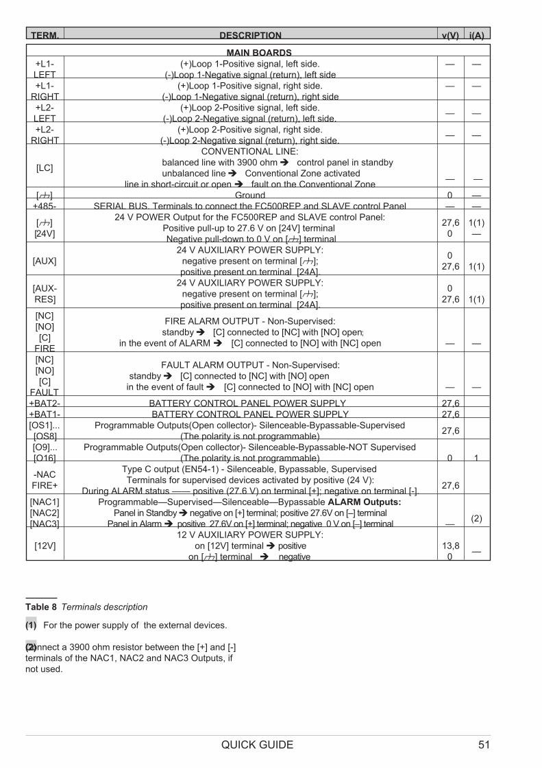
(1) For the power supply of the external devices.
(2)Connect a 3900 ohm resistor between the [+] and [-]
terminals of the NAC1, NAC2 and NAC3 Outputs, if
not used.
QUICK GUIDE 51
TERM. DESCRIPTION v(V) i(A)
MAIN BOARDS
+L1-
LEFT
(+)Loop 1-Positive signal, left side.
(-)Loop 1-Negative signal (return), left side
— —
+L1-
RIGHT
(+)Loop 1-Positive signal, right side.
(-)Loop 1-Negative signal (return), right side
— —
+L2-
LEFT
(+)Loop 2-Positive signal, left side.
(-)Loop 2-Negative signal (return), left side.— —
+L2-
RIGHT
(+)Loop 2-Positive signal, right side.
(-)Loop 2-Negative signal (return), right side.— —
[LC]
CONVENTIONAL LINE:
balanced line with 3900 ohm� control panel in standby
unbalanced line� Conventional Zone activated
line in short-circuit or open� fault on the Conventional Zone— —
[M] Ground 0 —
+485- SERIAL BUS. Terminals to connect the FC500REP and SLAVE control Panel — —
[M]
[24V]
24 V POWER Output for the FC500REP and SLAVE control Panel:
Positive pull-up to 27.6 V on [24V] terminal
Negative pull-down to 0 V on [M] terminal
27,6
0
1(1)
—
[AUX]
24 V AUXILIARY POWER SUPPLY:
negative present on terminal [M];
positive present on terminal [24A].
0
27,6 1(1)
[AUX-
RES]
24 V AUXILIARY POWER SUPPLY:
negative present on terminal [M];
positive present on terminal [24A].
0
27,6 1(1)
[NC]
[NO]
[C]
FIRE
FIRE ALARM OUTPUT - Non-Supervised:
standby� [C] connected to [NC] with [NO] open;
in the event of ALARM� [C] connected to [NO] with [NC] open — —
[NC]
[NO]
[C]
FAULT
FAULT ALARM OUTPUT - Non-Supervised:
standby� [C] connected to [NC] with [NO] open
in the event of fault� [C] connected to [NO] with [NC] open — —
+BAT2- BATTERY CONTROL PANEL POWER SUPPLY 27,6
+BAT1- BATTERY CONTROL PANEL POWER SUPPLY 27,6
[OS1]...
[OS8]
Programmable Outputs(Open collector)- Silenceable-Bypassable-Supervised
(The polarity is not programmable)27,6
[O9]...
[O16]
Programmable Outputs(Open collector)- Silenceable-Bypassable-NOT Supervised
(The polarity is not programmable) 0 1
-NAC
FIRE+
Type C output (EN54-1) - Silenceable, Bypassable, Supervised
Terminals for supervised devices activated by positive (24 V):
During ALARM status —— positive (27.6 V) on terminal [+]; negative on terminal [-].27,6
[NAC1]
[NAC2]
[NAC3]
Programmable—Supervised—Silenceable—Bypassable ALARM Outputs:
Panel in Standby� negative on [+] terminal; positive 27.6V on [–] terminal
Panel in Alarm� positive 27.6V on [+] terminal; negative 0 V on [–] terminal —(2)
[12V]
12 V AUXILIARY POWER SUPPLY:
on [12V] terminal� positive
on [M] terminal � negative
13,8
0—
Table 8 Terminals description

BENTEL SECURITY s.r.l.
Via Gabbiano, 22 - Zona Ind. S. Scolastica
64013 Corropoli (TE) - ITALY
Tel.: +39 0861 839060
Fax: +39 0861 839065
e-mail: [email protected]
http://www.bentelsecurity.com ISTISBLEFC520 0.0 091007 V10
Related Documents