Gabriel S. Sobral and Luiz C. S. Góes FAULT DETECTION AND ISOLATION BASED ON BOND GRAPH MODELS: APPLICATION TO AN ELECTROMECHANICAL ACTUATOR 8-9 October 2019, Stockholm, Sweden Aerospace Technology Congress 2019 Swedish Society of Aeronautics and Astronautics (FTF) Department of Mechanical Engineering Instituto Tecnológico de Aeronáutica (ITA) São José dos Campos, SP/Brazil

Welcome message from author
This document is posted to help you gain knowledge. Please leave a comment to let me know what you think about it! Share it to your friends and learn new things together.
Transcript
Gabriel S. Sobral and Luiz C. S. Góes
FAULT DETECTION AND ISOLATION BASED ONBOND GRAPH MODELS: APPLICATION TO AN
ELECTROMECHANICAL ACTUATOR
8-9 October 2019, Stockholm, Sweden
Aerospace Technology Congress 2019
Swedish Society of Aeronautics and Astronautics (FTF)
Department of Mechanical EngineeringInstituto Tecnológico de Aeronáutica (ITA)
São José dos Campos, SP/Brazil

AGENDA01.
02. Fault Detection and Isolation
03.
04.
Electromechanical Actuator Model
IntroductionResearch Motivation and Objectives
Diagnostic Bond Graph Model
05. Simulation and ResultsConclusions
3
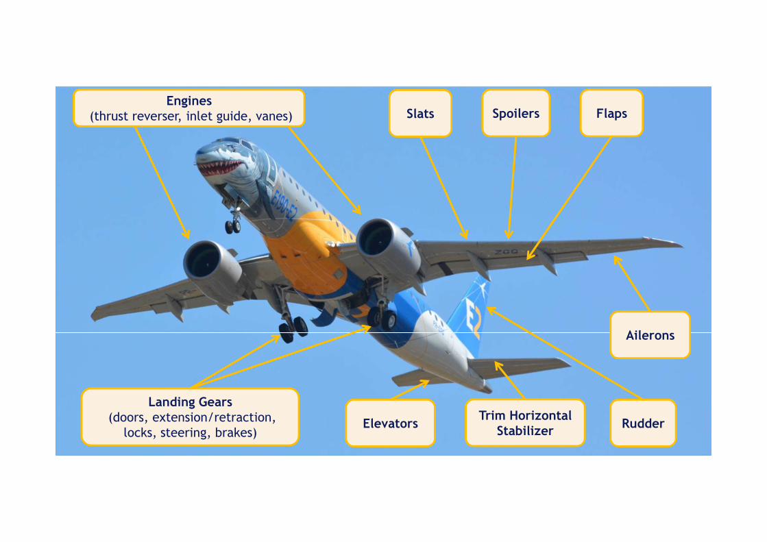
Slats Spoilers Flaps
Landing Gears(doors, extension/retraction,
locks, steering, brakes)Elevators
Trim HorizontalStabilizer
Rudder
Ailerons
Engines(thrust reverser, inlet guide, vanes)
4
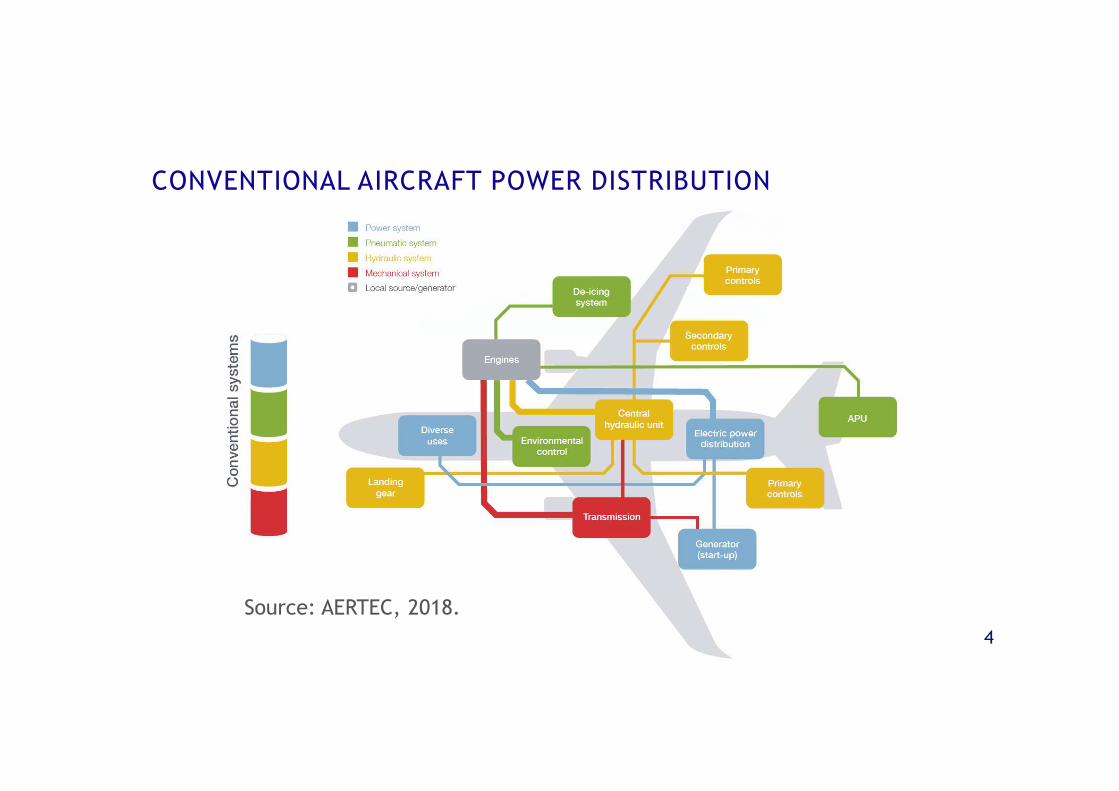
CONVENTIONAL AIRCRAFT POWER DISTRIBUTION
Source: AERTEC, 2018.
5
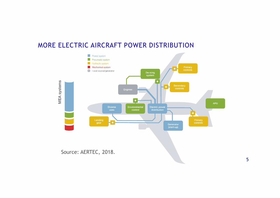
MORE ELECTRIC AIRCRAFT POWER DISTRIBUTION
Source: AERTEC, 2018.
6
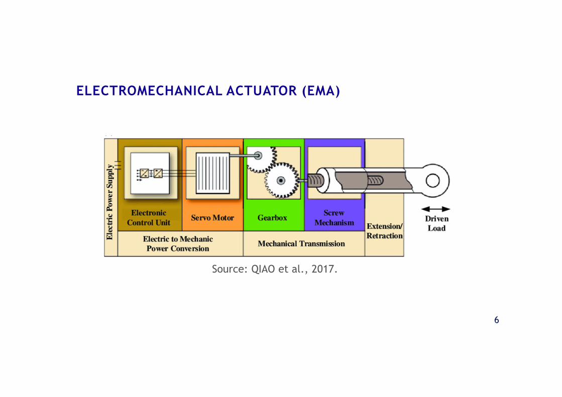
ELECTROMECHANICAL ACTUATOR (EMA)
Source: QIAO et al., 2017.
7
• Industry trend towards power-by-
wire actuators with evolution of the
More Electric Aircraft concept
• Lack of accumulated knowledge and
experience regarding EMA reliability
and the risk of failures
RESEARCHMOTIVATION
8
• Industry trend towards power-by-
wire actuators with evolution of the
More Electric Aircraft concept
• Lack of accumulated knowledge and
experience regarding EMA reliability
and the risk of failures
• Study and implementation of a
quantitative model-based fault
detection and isolation methodology
based on bond graph
• Application to an EMA model
RESEARCHMOTIVATION
RESEARCHOBJECTIVES
FAULT DETECTION AND ISOLATION
10
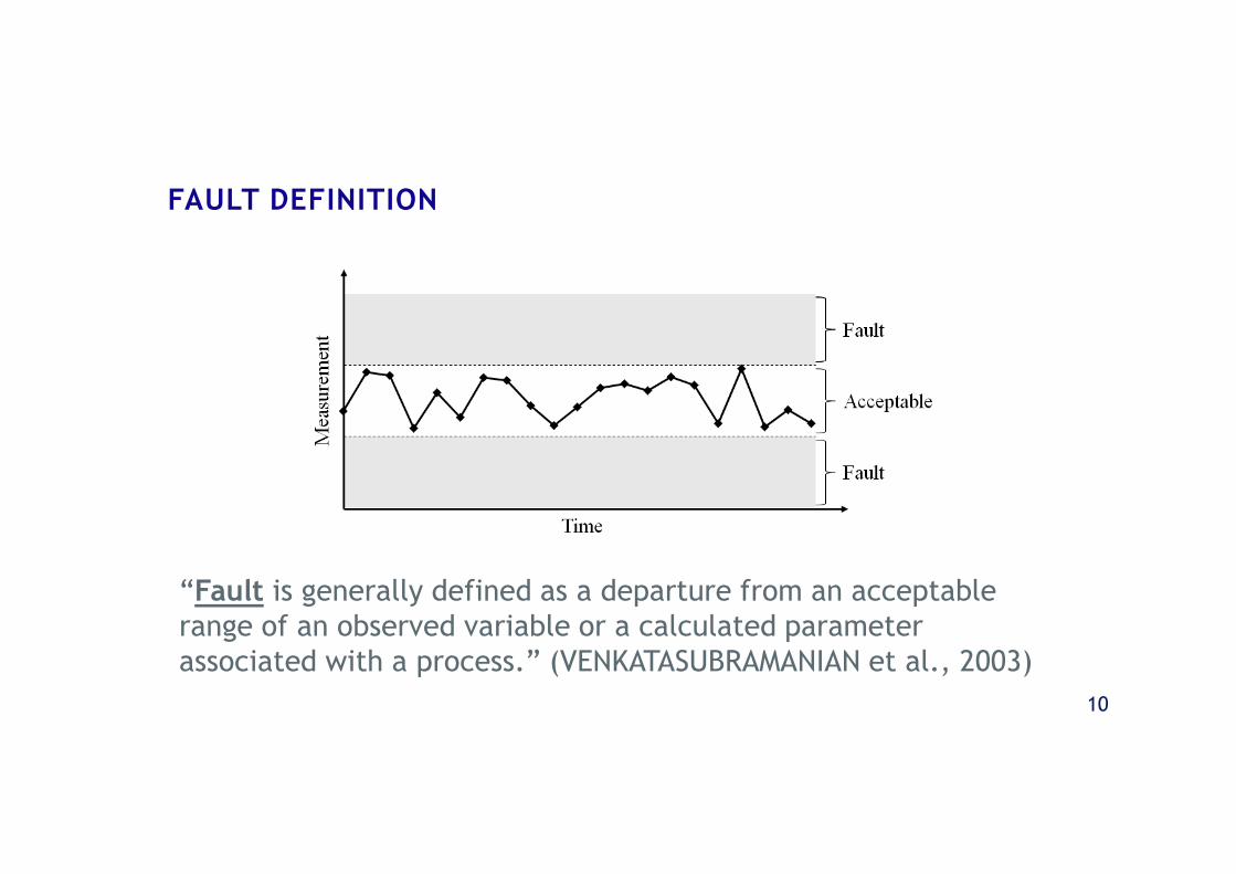
FAULT DEFINITION
“Fault is generally defined as a departure from an acceptablerange of an observed variable or a calculated parameterassociated with a process.” (VENKATASUBRAMANIAN et al., 2003)
11
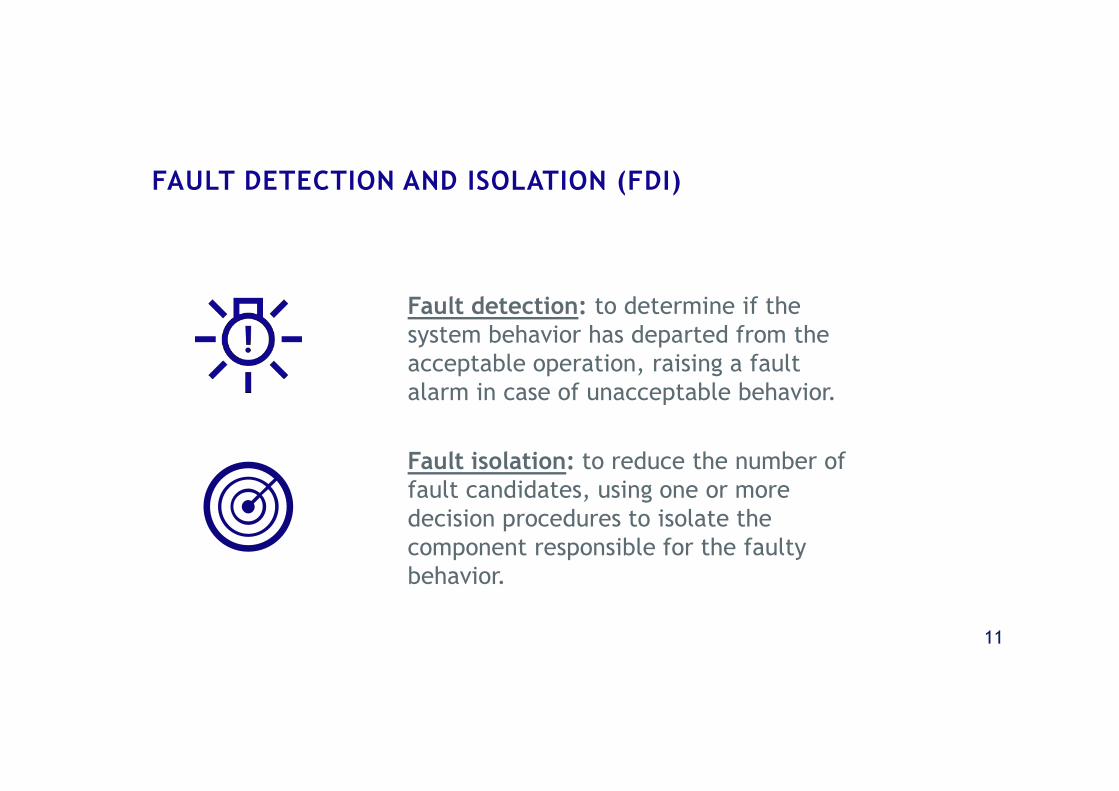
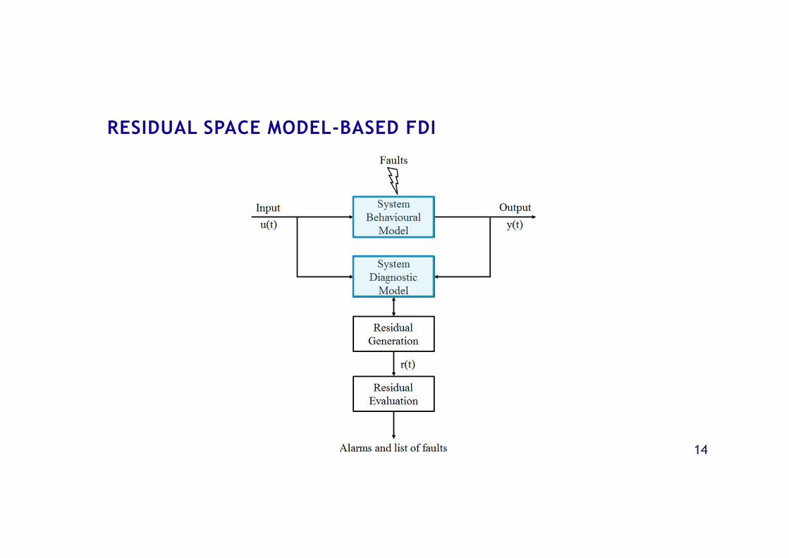
FAULT DETECTION AND ISOLATION (FDI)
Fault detection: to determine if thesystem behavior has departed from theacceptable operation, raising a faultalarm in case of unacceptable behavior.
Fault isolation: to reduce the number offault candidates, using one or moredecision procedures to isolate thecomponent responsible for the faultybehavior.
12
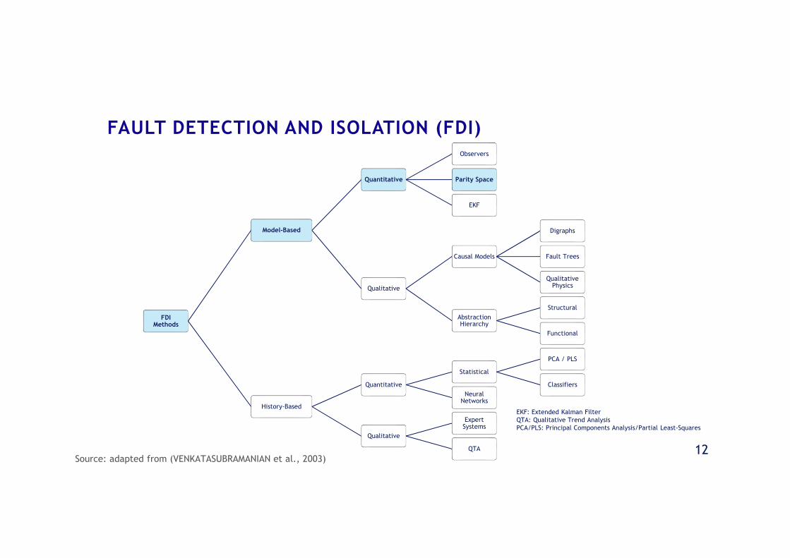
FAULT DETECTION AND ISOLATION (FDI)
FDIMethods
Model-Based
Quantitative
Observers
Parity Space
EKF
Qualitative
Causal Models
Digraphs
Fault Trees
QualitativePhysics
AbstractionHierarchy
Structural
Functional
History-Based
Quantitative
Statistical
PCA / PLS
Classifiers
NeuralNetworks
Qualitative
ExpertSystems
QTA
EKF: Extended Kalman FilterQTA: Qualitative Trend AnalysisPCA/PLS: Principal Components Analysis/Partial Least-Squares
Source: adapted from (VENKATASUBRAMANIAN et al., 2003)
13
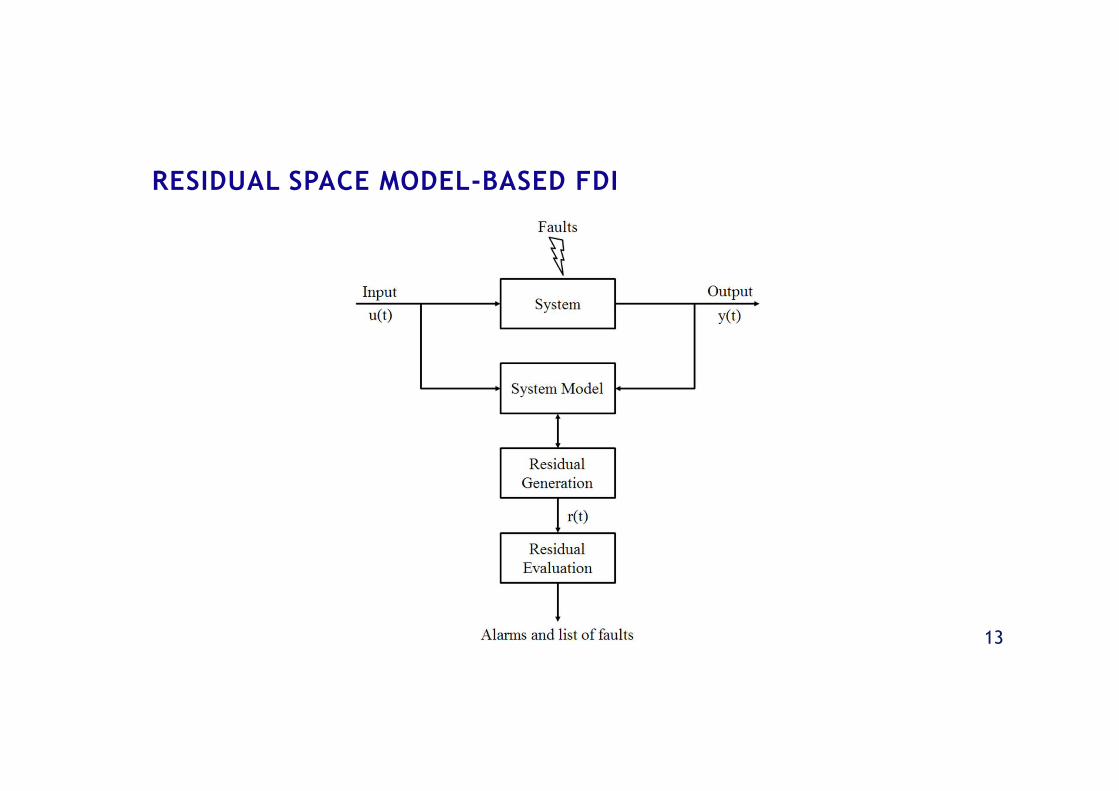
RESIDUAL SPACE MODEL-BASED FDI
14
RESIDUAL SPACE MODEL-BASED FDI

ELECTROMECHANICALACTUATOR MODEL
16
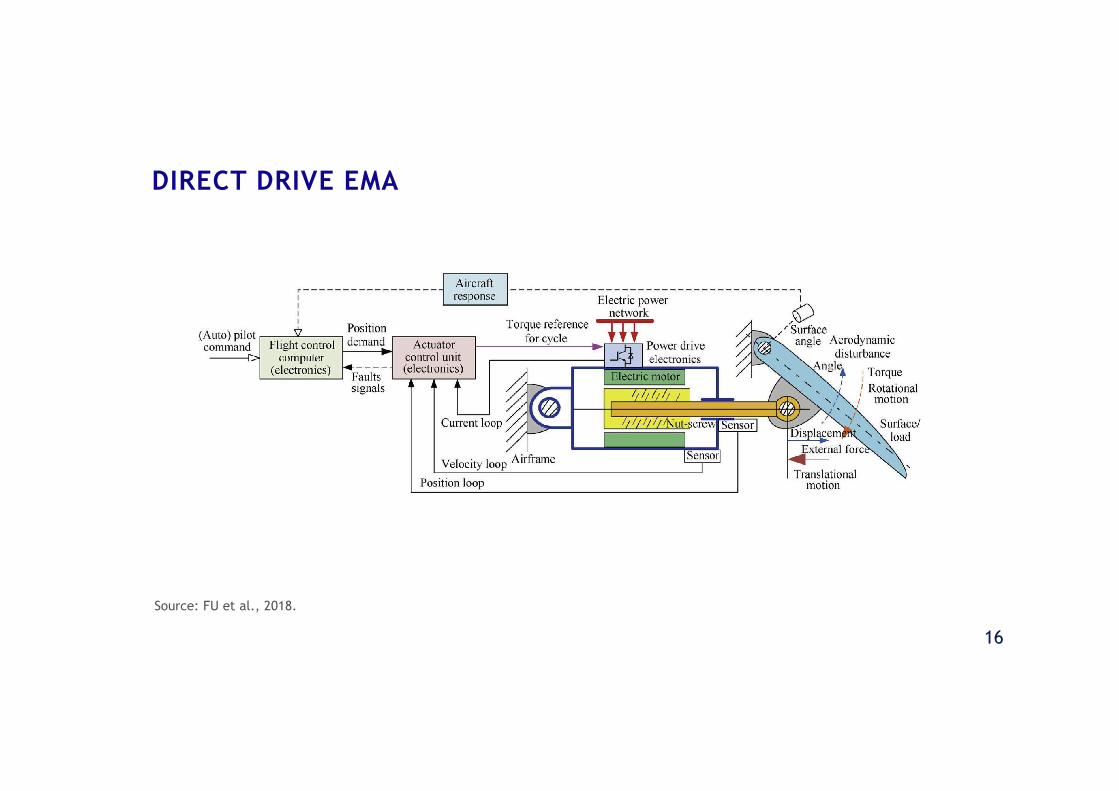
DIRECT DRIVE EMA
Source: FU et al., 2018.
17
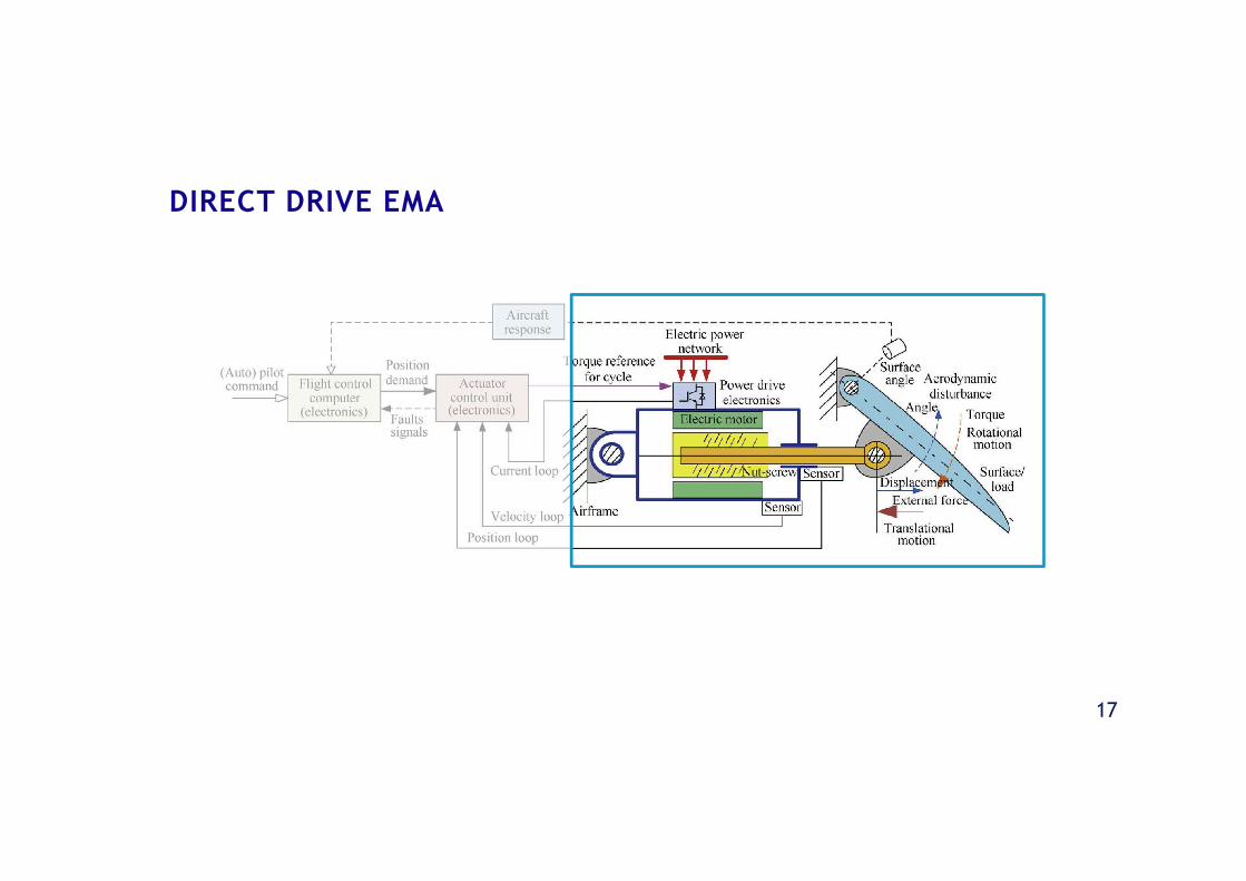
DIRECT DRIVE EMA
18
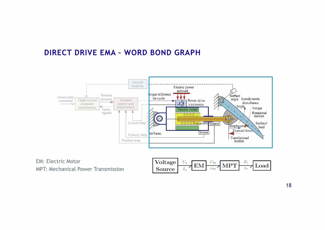
DIRECT DRIVE EMA – WORD BOND GRAPH
EM: Electric Motor
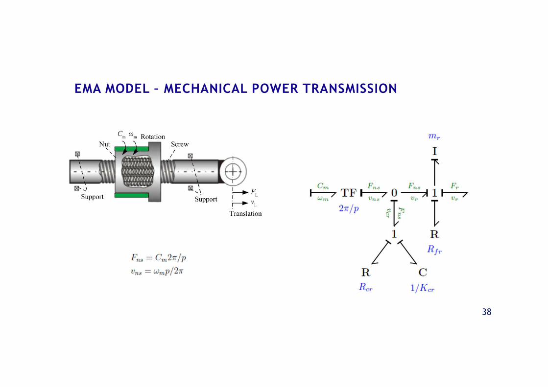
MPT: Mechanical Power Transmission
19
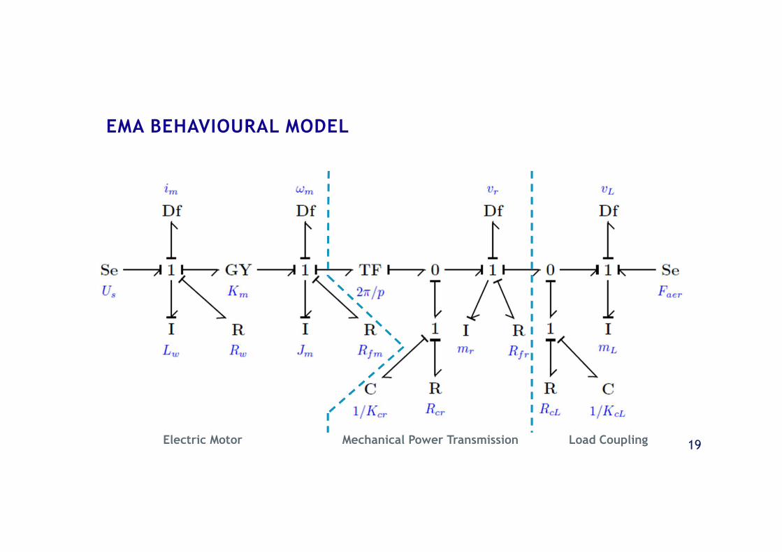
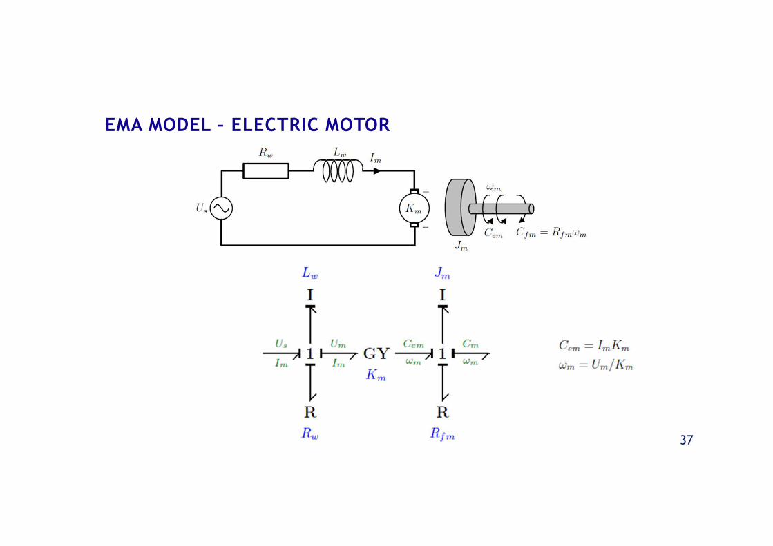
EMA BEHAVIOURAL MODEL
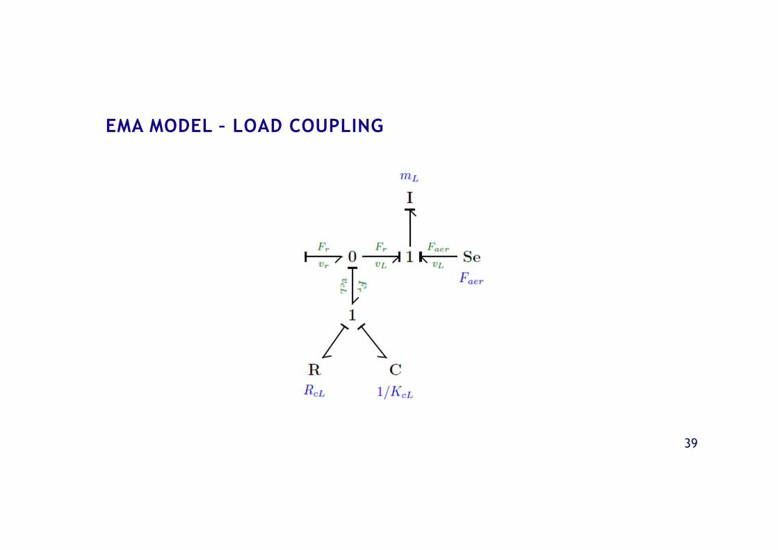
Electric Motor Mechanical Power Transmission Load Coupling
20
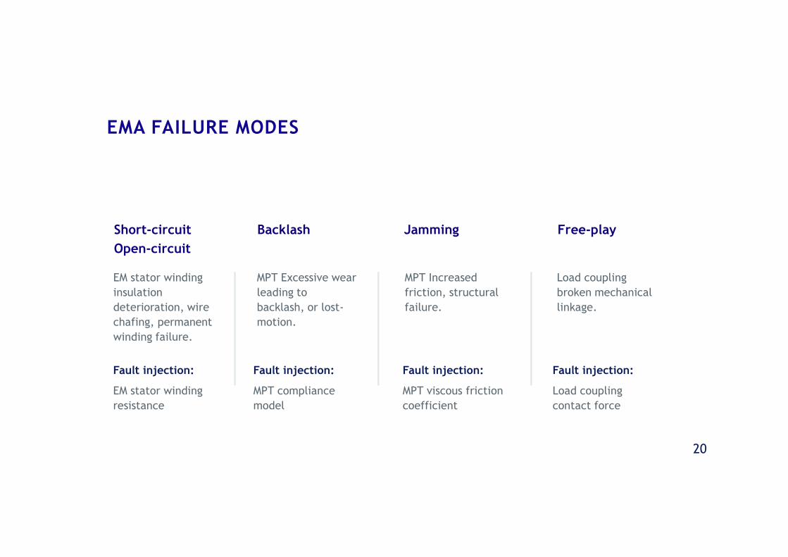
EM stator winding
insulation
deterioration, wire
chafing, permanent
winding failure.
MPT Excessive wear
leading to
backlash, or lost-
motion.
MPT Increased
friction, structural
failure.
Load coupling
broken mechanical
linkage.
Short-circuit
Open-circuit
Backlash Jamming Free-play
EMA FAILURE MODES
Fault injection:
EM stator winding
resistance
Fault injection:
MPT compliance
model
Fault injection:
MPT viscous friction
coefficient
Fault injection:
Load coupling
contact force
DIAGNOSTIC BOND GRAPHMODEL
22
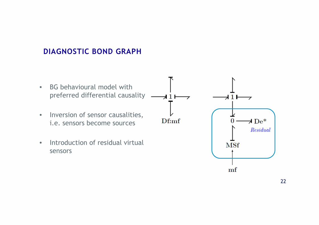
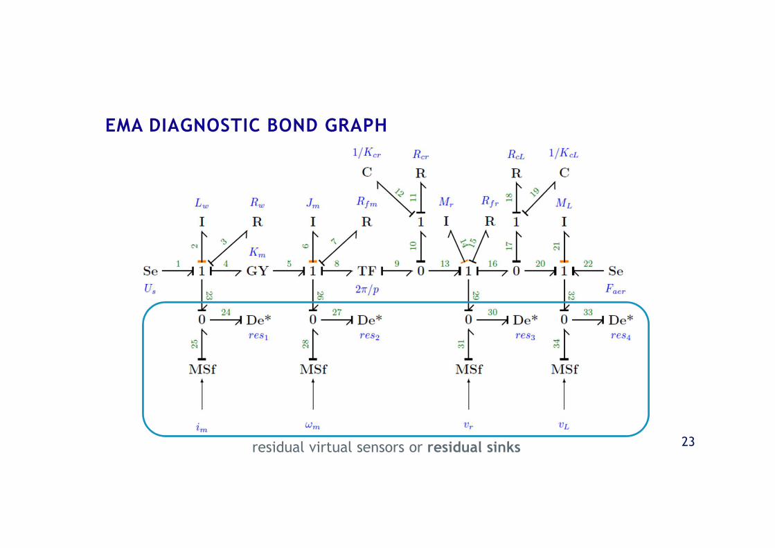
DIAGNOSTIC BOND GRAPH
• BG behavioural model withpreferred differential causality
• Inversion of sensor causalities,i.e. sensors become sources
• Introduction of residual virtualsensors
23
EMA DIAGNOSTIC BOND GRAPH
residual virtual sensors or residual sinks
24
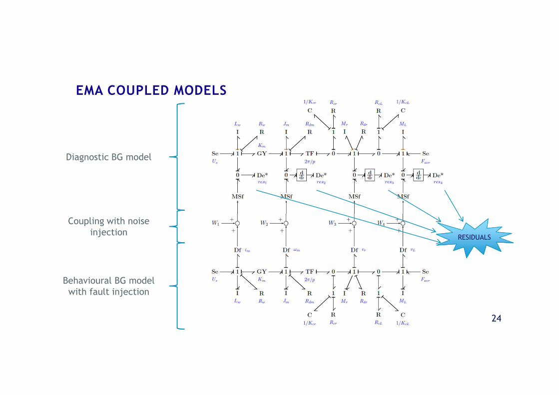
EMA COUPLED MODELS
RESIDUALS
Behavioural BG modelwith fault injection
Coupling with noiseinjection
Diagnostic BG model
25
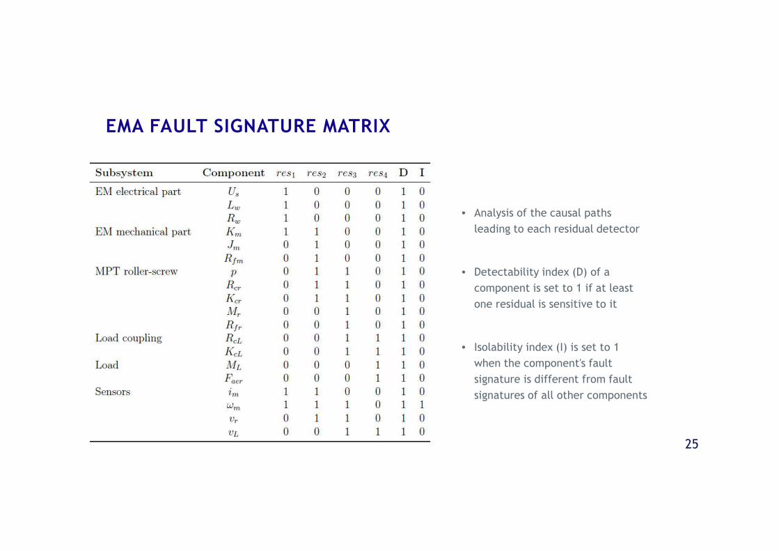
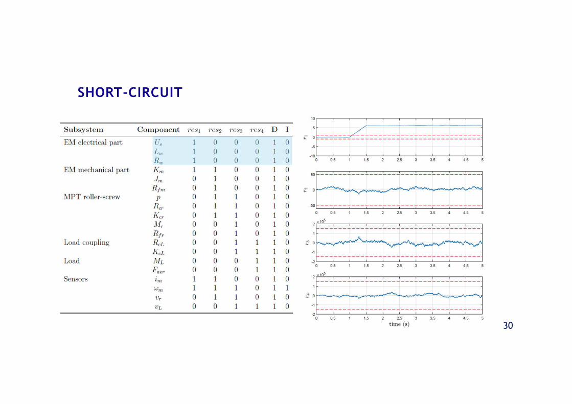
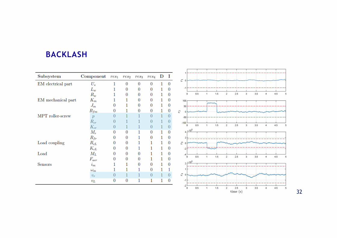
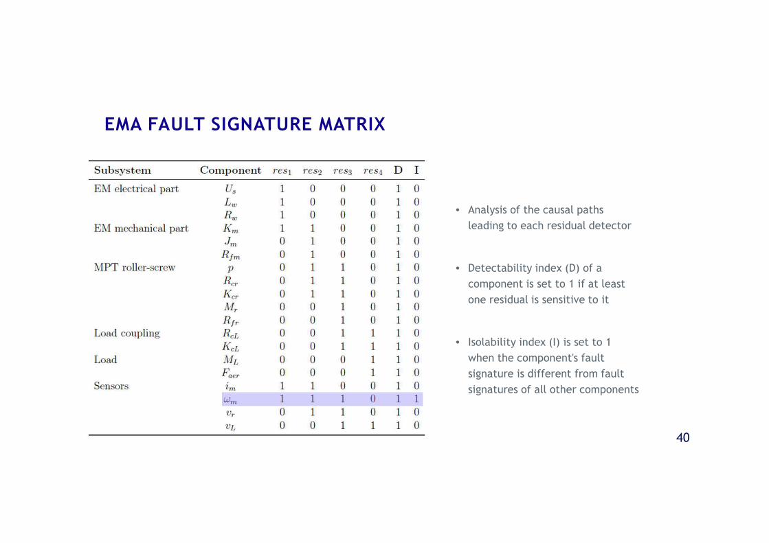
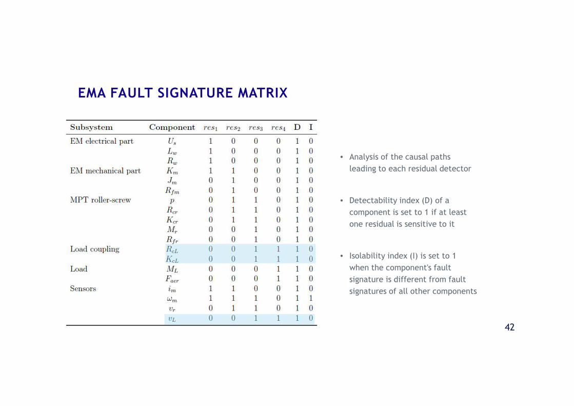
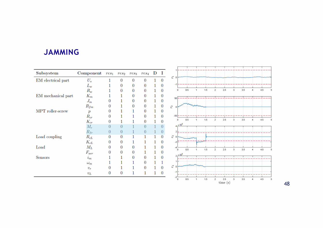
• Analysis of the causal paths
leading to each residual detector
• Detectability index (D) of a
component is set to 1 if at least
one residual is sensitive to it
• Isolability index (I) is set to 1
when the component's fault
signature is different from fault
signatures of all other components
EMA FAULT SIGNATURE MATRIX
SIMULATION AND RESULTS

27
20-SIM BG MODEL IMPLEMENTATION
28
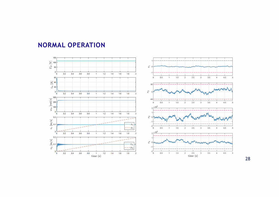
NORMAL OPERATION
29
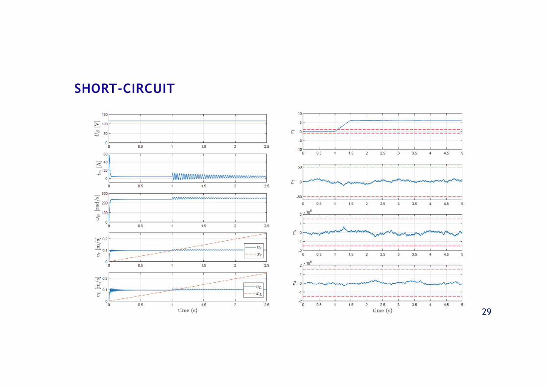
SHORT-CIRCUIT
30
SHORT-CIRCUIT
31
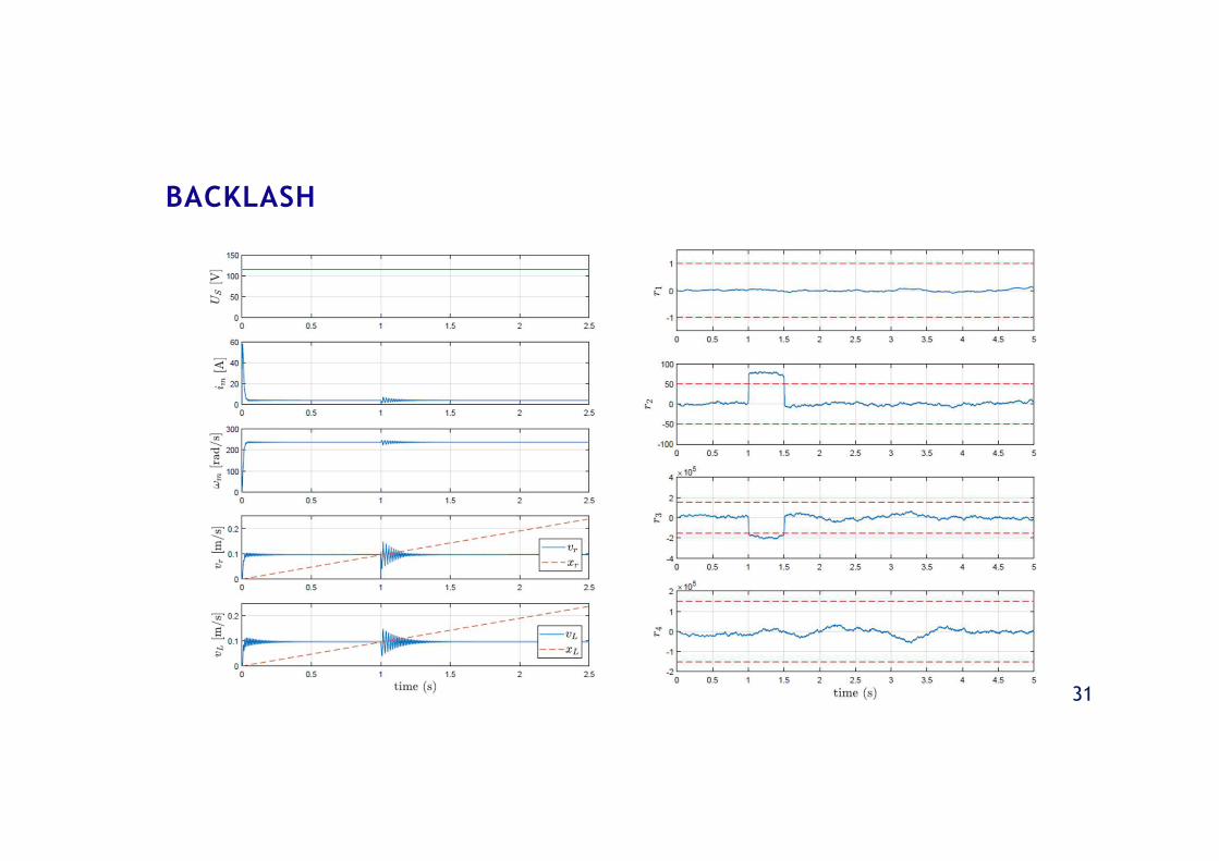
BACKLASH
32
BACKLASH
33
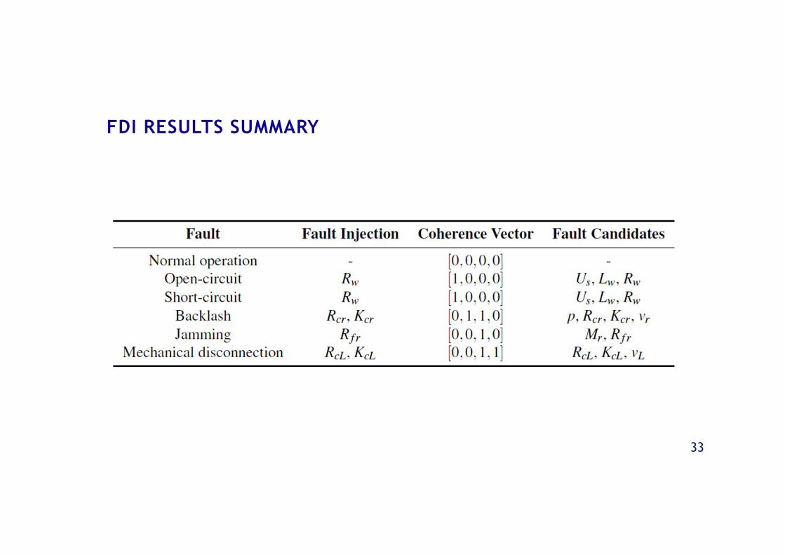
FDI RESULTS SUMMARY
34
The Diagnostic Bond Graph approach was
proven as a powerful tool, suitable for the
implementation of FDI on complex
multidisciplinary systems, such as the
electromechanical actuator.
CONCLUSIONS

36
BIBLIOGRAPHY
BALABAN, E.; SAXENA, A.; BANSAL, P.; GOEBEL, K. F.; STOELTING, P.; CURRAN, S. A diagnostic approach forelectro-mechanical actuators in aerospace systems. In: IEEE AEROSPACE CONFERENCE, 2009, Big Sky.Proceedings [...]. Piscataway: IEEE, 2009. p. 1-13.
BORUTZKY, W. Bond graph methodology: development and analysis of multidisciplinary dynamic systemmodels. London: Springer, 2010. 662p.
FU, J.; MARÉ, J. C.; YU, L.; FU, Y. Multi-level virtual prototyping of electromechanical actuation systemfor more electric aircraft. Chinese Journal of Aeronautics, v. 31, n. 5, p. 892–913, 2018.
QIAO, G.; LIU, G.; SHI, Z.; WANG, Y.; MA, S.; LIM, T. C. A review of electromechanical actuators forMore/All Electric aircraft systems. Proceedings of the Institution of Mechanical Engineers, Part C:Journal of Mechanical Engineering Science, 2017.
SAMANTARAY, A. K.; BOUAMAMA, B. O. Model-based process supervision: a bond graph approach. London:Springer, 2008. 471 p.
37
EMA MODEL – ELECTRIC MOTOR
38
EMA MODEL – MECHANICAL POWER TRANSMISSION
39
EMA MODEL – LOAD COUPLING
40
• Analysis of the causal paths
leading to each residual detector
• Detectability index (D) of a
component is set to 1 if at least
one residual is sensitive to it
• Isolability index (I) is set to 1
when the component's fault
signature is different from fault
signatures of all other components
EMA FAULT SIGNATURE MATRIX

41
• Analysis of the causal paths
leading to each residual detector
• Detectability index (D) of a
component is set to 1 if at least
one residual is sensitive to it
• Isolability index (I) is set to 1
when the component's fault
signature is different from fault
signatures of all other components
EMA FAULT SIGNATURE MATRIX
42
• Analysis of the causal paths
leading to each residual detector
• Detectability index (D) of a
component is set to 1 if at least
one residual is sensitive to it
• Isolability index (I) is set to 1
when the component's fault
signature is different from fault
signatures of all other components
EMA FAULT SIGNATURE MATRIX

43
OPEN-CIRCUIT

44
OPEN-CIRCUIT
45
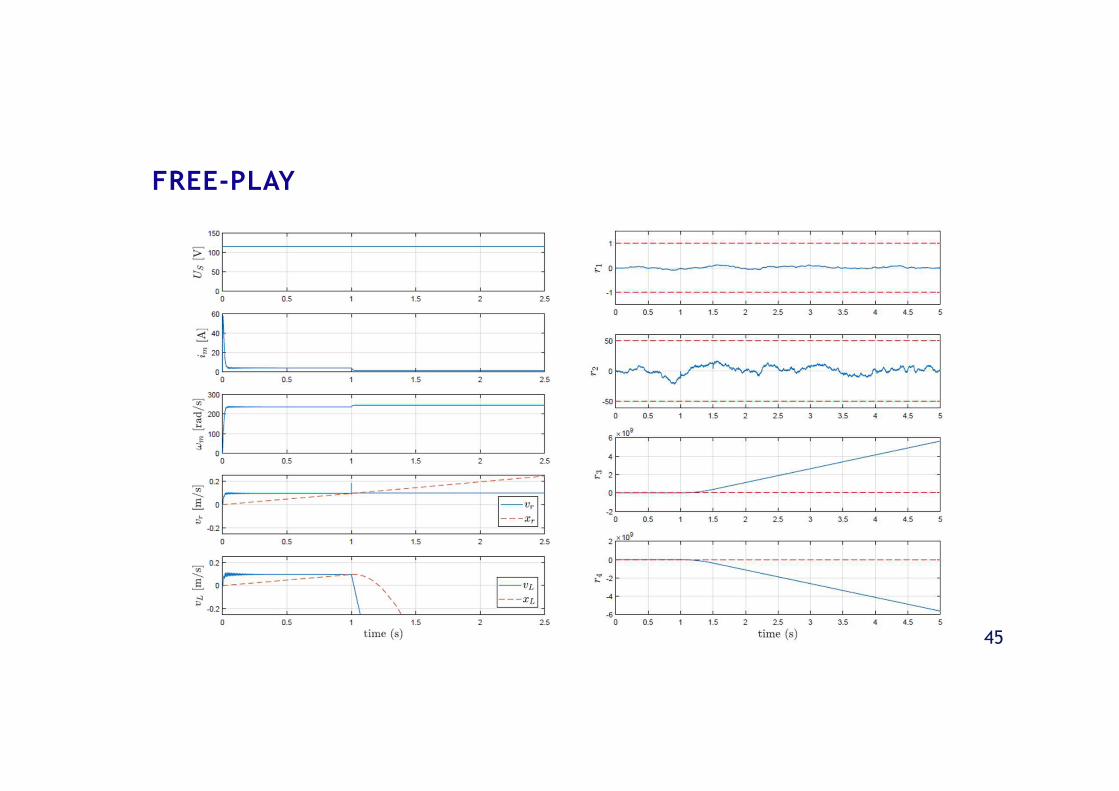
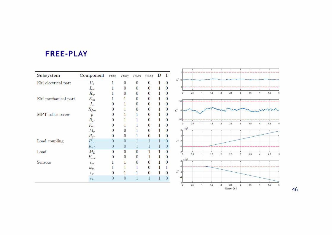
FREE-PLAY
46
FREE-PLAY
47
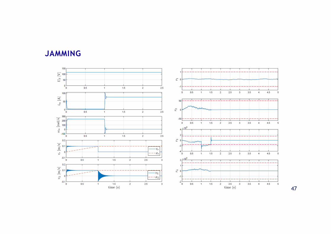
JAMMING
48
JAMMING

49
1. Refinement of the EMA model, including PDE and
actuator control;
2. Analysis of the closed loop response, and its
impacts over the response to failure modes;
3. Robust FDI and sensitivity analysis of the residuals
in the presence of parameter uncertainties;
4. Evaluate the inclusion of more sensors in order to
improve faults isolability;
5. Bicausal Bond Graph (BBG) models for analysis and
improvement of sensor placement for better
isolability;
6. Multiple-fault scenarios, applying multiple-fault
isolation techniques;
7. Fault Tolerant Control (FTC) techniques for fault
accommodation / passivation;
8. DBG online simulation, with inputs from a real
system.
FUTURERESEARCH
50
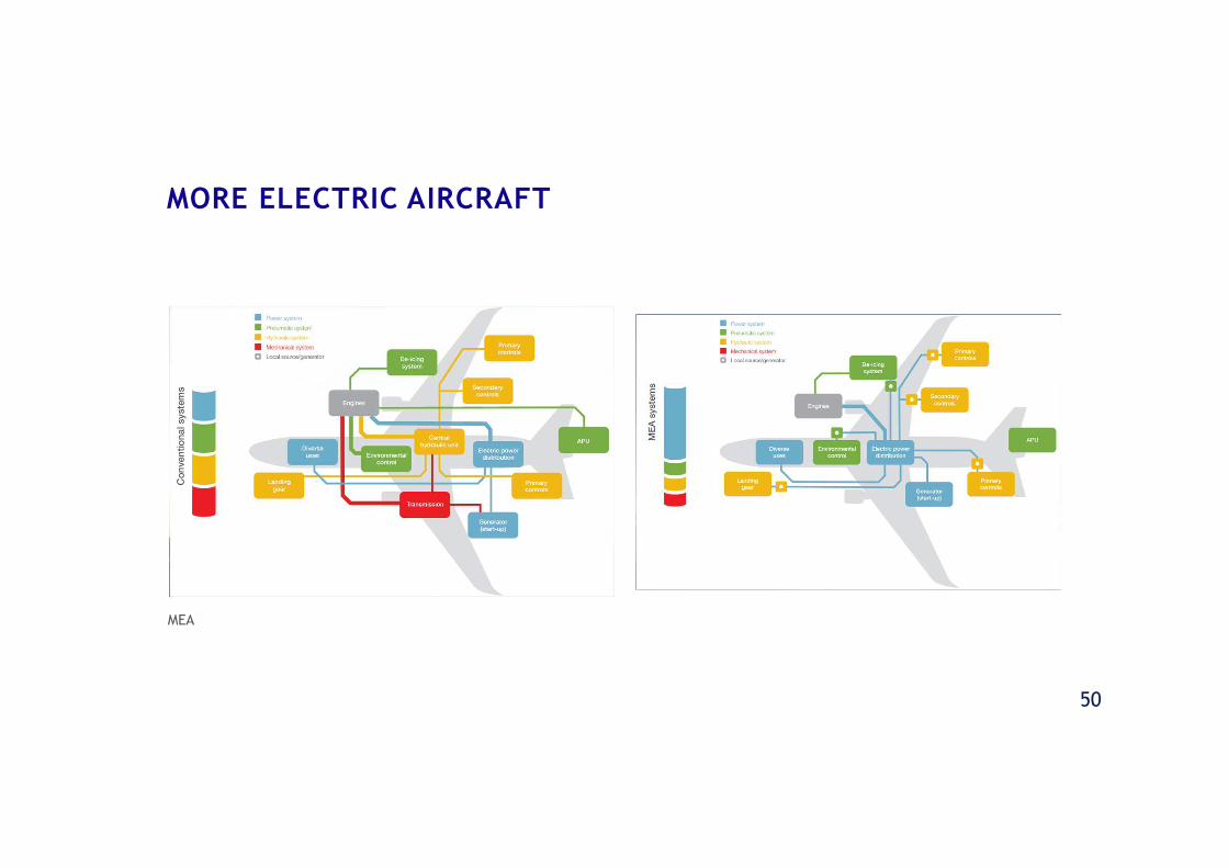
MEA
MORE ELECTRIC AIRCRAFT
51
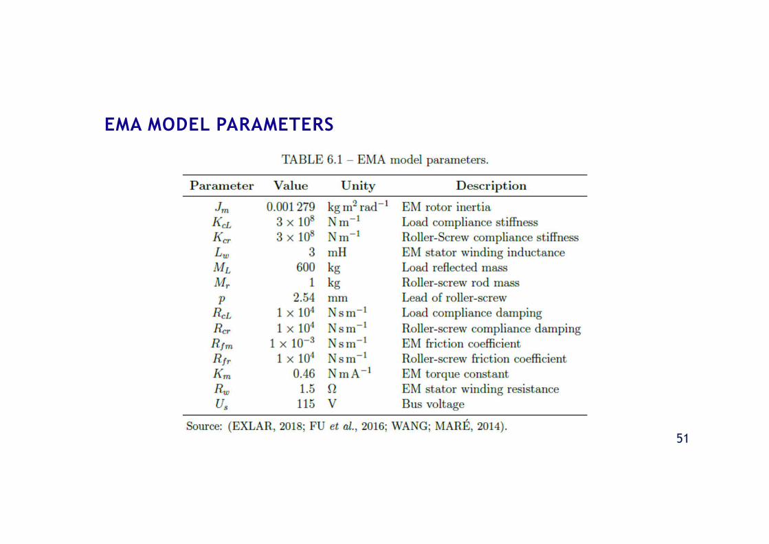
EMA MODEL PARAMETERS
52
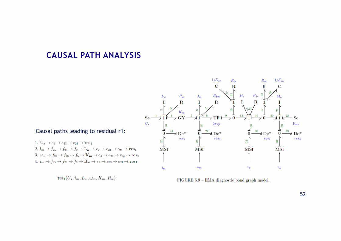
CAUSAL PATH ANALYSIS
Causal paths leading to residual r1:

53
BACKLASH MODEL
54
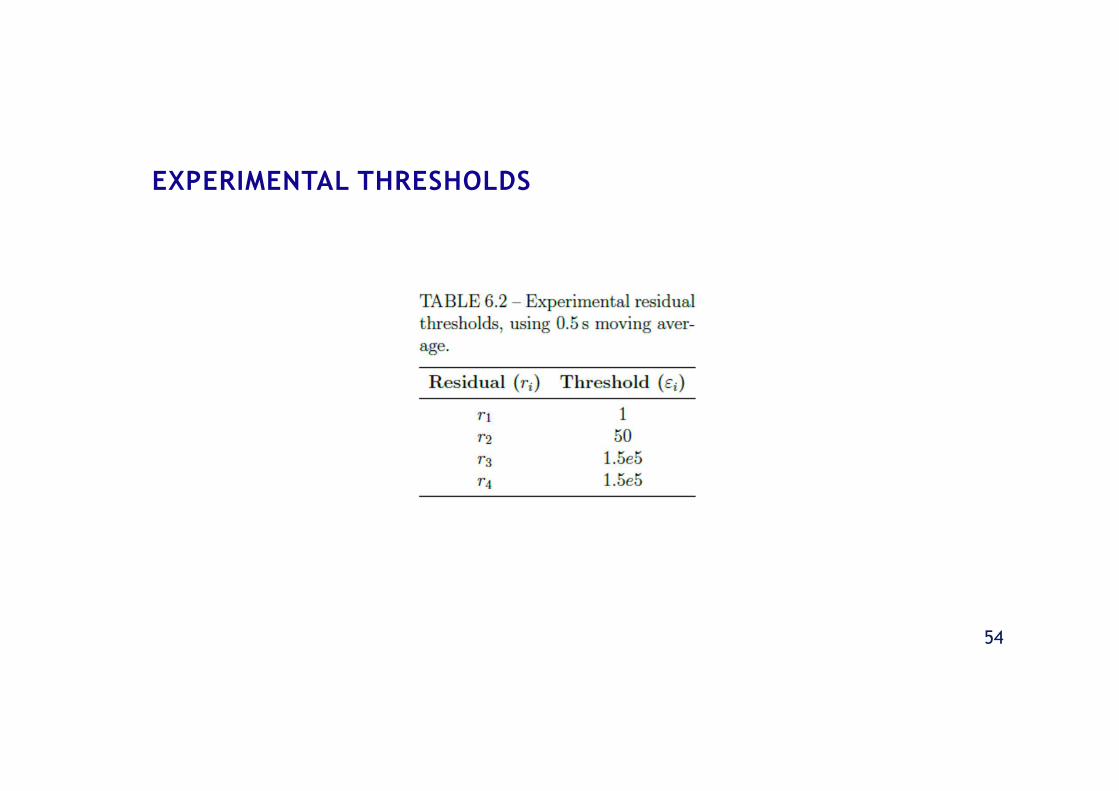
EXPERIMENTAL THRESHOLDS
55
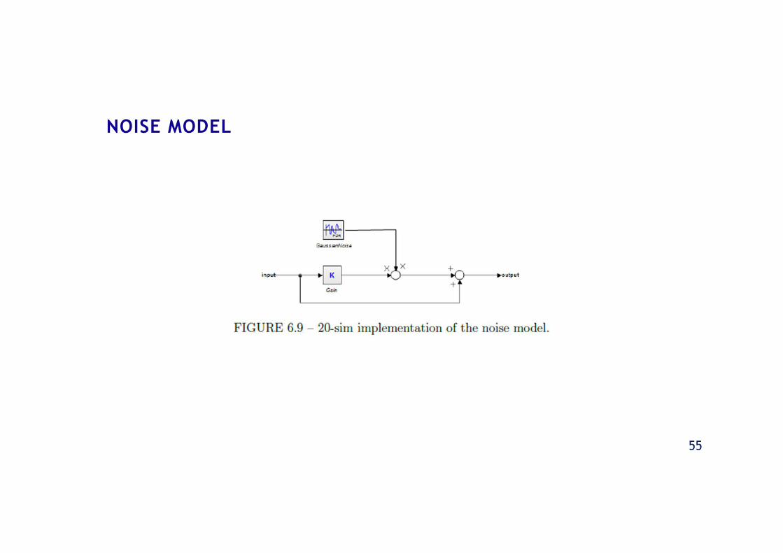
NOISE MODEL
Related Documents


