FAILURES DUE TO SHEAR BY : SAURABH SHAH CODE : 1710 FACULTY : PROF. R.J.SHAH

Failures Due to Shear
Nov 22, 2014
Welcome message from author
This document is posted to help you gain knowledge. Please leave a comment to let me know what you think about it! Share it to your friends and learn new things together.
Transcript
FAILURES DUE TO SHEAR
BY : SAURABH SHAH
CODE : 1710
FACULTY : PROF. R.J.SHAH
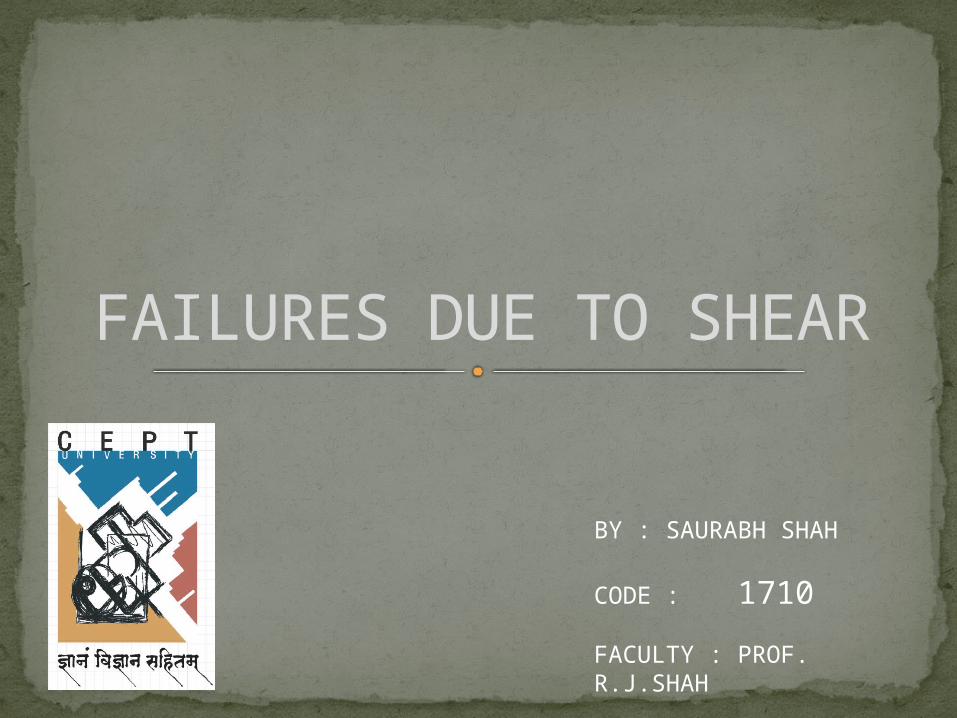
Definition: Shear failure is actually a diagonal tension failure that is
brittle in nature and should be avoided. To better understand diagonal tension consider the basic
mechanics of a beam with no shear web reinforcing:
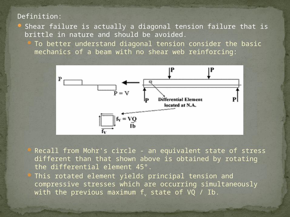
Recall from Mohr's circle - an equivalent state of stress different than that shown above is obtained by rotating the differential element 45°.
This rotated element yields principal tension and compressive stresses which are occurring simultaneously with the previous maximum fv state of VQ / Ib.
In general this ft will exceed the inherent tensile strength of masonry, before fv exceeds masonry shear strength. When this happens, diagonal cracks, originating at
the N.A begin to occur and grow with increases in beam loading.
IntroductionShear Transfer Action and MechanismsFailure Modes in Shear (Without Web
Reinforcement)Factors affecting ShearFailure of corbels in shearCase studyFew pictures of shear failureBibliography
Contents
• The early use of reinforced concrete was characterized by a
large number of patented “systems”, the design methods of
which were generally not brought to public attention.
• Study of the historical development of shear design was
required so as to find out the problems in basic shear design
from the early days.
• The equations were brought to the codes after many
experiments and research work done by numerous people.
INTRODUCTION
• Early pioneers of reinforced concrete before the year 1900
developed two schools of thought pertaining to the
mechanism of shear failures in reinforced concrete
members.
• One school of thought considered horizontal shear as the
basic cause of shear failure , The second school of thought,
accepted by nearly all engineers today, considered diagonal
tension the basic cause of shear failures.
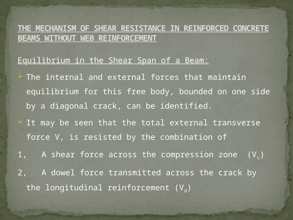
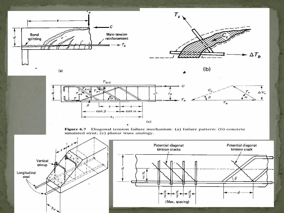
Equilibrium in the Shear Span of a Beam:
The internal and external forces that maintain equilibrium
for this free body, bounded on one side by a diagonal crack,
can be identified.
It may be seen that the total external transverse force V, is
resisted by the combination of
1, A shear force across the compression zone (Vc)
2, A dowel force transmitted across the crack by the
longitudinal reinforcement (Vd)
THE MECHANISM OF SHEAR RESISTANCE IN REINFORCED CONCRETE BEAMS WITHOUT WEB REINFORCEMENT
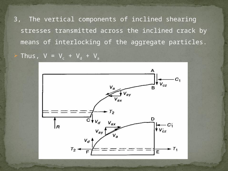
3, The vertical components of inclined shearing stresses
transmitted across the inclined crack by means of
interlocking of the aggregate particles.
Thus, V = Vc + Vd + Va
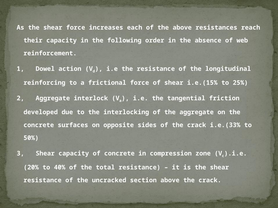
As the shear force increases each of the above resistances reach
their capacity in the following order in the absence of web
reinforcement.
1, Dowel action (Vd), i.e the resistance of the longitudinal
reinforcing to a frictional force of shear i.e.(15% to 25%)
2, Aggregate interlock (Va), i.e. the tangential friction developed
due to the interlocking of the aggregate on the concrete
surfaces on opposite sides of the crack i.e.(33% to 50%)
3, Shear capacity of concrete in compression zone (Vc).i.e.(20%
to 40% of the total resistance) – it is the shear resistance of the
uncracked section above the crack.
As load is applied to the beam, the noticeable change is the
formation of practically vertical tension cracks in the region
of maximum moment. Here the cracks develop almost
perpendicular to the axis of the beam. These are called
flexural cracks.
With increasing load, additional cracks form closer to the
supports and some of the cracks become slightly inclined
toward the load.
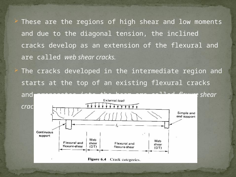
These are the regions of high shear and low moments and
due to the diagonal tension, the inclined cracks develop as
an extension of the flexural and are called web shear cracks.
The cracks developed in the intermediate region and starts
at the top of an existing flexural cracks and propagates into
the beam are called flexure shear cracks.
The contribution of shear reinforcement to the shear strength of a reinforced concrete beam can be described as follows:
It resists part of the shear, Vs. The stirrup passing across
the cracks carries shear directly.
It increases the magnitude of the interface shear, Va, by
resisting the growth of the inclined crack. By limiting the
opening of diagonal cracks within the elastic range, it
enhances and preserves shear transfer by aggregate
interlock.
It increases the dowel force, Vd in the longitudinal bars,
thereby improving the dowel action. A stirrup can
effectively support a longitudinal bar that is being crossed
by a flexural shear crack close to it. It restrains the bars
from prying off the covering concrete.
The confining action of the stirrups in the compression
concrete may increase its strength.
It suppresses flexural tensile stresses by the means of the
diagonal compression force resulting from truss action. The
holding together of the concrete on the two sides of the
cracks help keep the cracks from moving into the
compression zone of the beam.
The confining action of stirrups on the concrete increases
the rotation capacity of plastic hinges that develop in a
member at ultimate load and increases the length over
which yielding takes place. These stirrups wrapped around
the core of concrete act like hoops and thus increases the
beam’s strength and ductility.
It can be said that suitably detailed web reinforcement will
preserve the integrity, therefore the strength, of the beam
mechanism, allowing additional shear forces to be resisted
by truss mechanism.
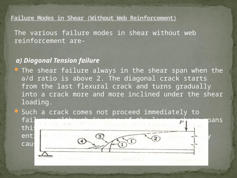
The various failure modes in shear without web reinforcement are-
a) Diagonal Tension failure The shear failure always in the shear span when the a/d
ratio is above 2. The diagonal crack starts from the last flexural crack and turns gradually into a crack more and more inclined under the shear loading.
Such a crack comes not proceed immediately to failure, although in some of the longer shear spans this either seems almost to be the case or an entirely new and flatter diagonal crack suddenly causes failure.
Failure Modes in Shear (Without Web Reinforcement)
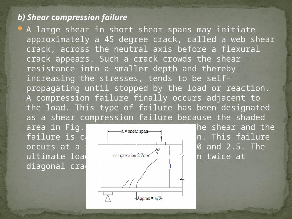
b) Shear compression failure A large shear in short shear spans may initiate
approximately a 45 degree crack, called a web shear crack, across the neutral axis before a flexural crack appears. Such a crack crowds the shear resistance into a smaller depth and thereby increasing the stresses, tends to be self-propagating until stopped by the load or reaction. A compression failure finally occurs adjacent to the load. This type of failure has been designated as a shear compression failure because the shaded area in Fig. also carries most of the shear and the failure is caused by the combination. This failure occurs at a range of a/d between 1.0 and 2.5. The ultimate load is sometimes more than twice at diagonal cracking.
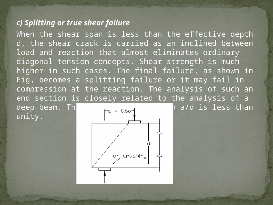
c) Splitting or true shear failure
When the shear span is less than the effective depth d, the shear crack is carried as an inclined between load and reaction that almost eliminates ordinary diagonal tension concepts. Shear strength is much higher in such cases. The final failure, as shown in Fig, becomes a splitting failure or it may fail in compression at the reaction. The analysis of such an end section is closely related to the analysis of a deep beam. This failure occurs when a/d is less than unity.
Influence of Shear span to depth ratio on Shear
Shear resistance of beams decrease with the increase of shear span to depth ratio
It is well established in both British and American design practice ( Evans and Kong, 1967) (ACI-ASCE Committee 426, 1973) that the failure mode of rectangular reinforced concrete beams without shear reinforcement is strongly dependent on the shear span/depth ratio.
(a) for a/d > 6, failure usually occurs in bending;
(b) for 6 > a/d >2.5. the development of a flexural crack into an inclined flexure-shear
crack results in diagonal tension failure,
(c) for 2.5 > a/d > 1, a diagonal crack forms independently but the beam remains stable
until shear-compression failure occurs;
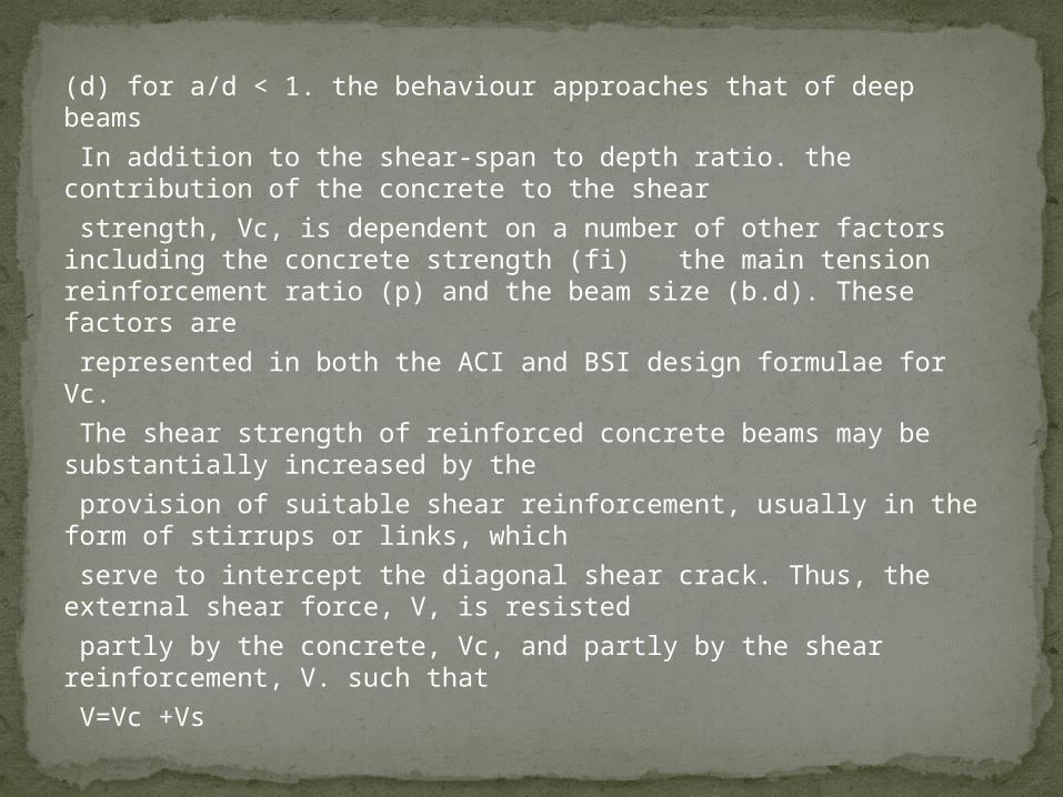
(d) for a/d < 1. the behaviour approaches that of deep beams
In addition to the shear-span to depth ratio. the contribution of the concrete to the shear
strength, Vc, is dependent on a number of other factors including the concrete strength (fi) the main tension reinforcement ratio (p) and the beam size (b.d). These factors are
represented in both the ACI and BSI design formulae for Vc.
The shear strength of reinforced concrete beams may be substantially increased by the
provision of suitable shear reinforcement, usually in the form of stirrups or links, which
serve to intercept the diagonal shear crack. Thus, the external shear force, V, is resisted
partly by the concrete, Vc, and partly by the shear reinforcement, V. such that
V=Vc +Vs
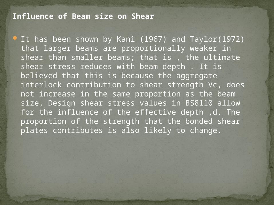
Influence of Beam size on Shear
It has been shown by Kani (1967) and Taylor(1972) that larger beams are proportionally weaker in shear than smaller beams; that is , the ultimate shear stress reduces with beam depth . It is believed that this is because the aggregate interlock contribution to shear strength Vc, does not increase in the same proportion as the beam size, Design shear stress values in BS8110 allow for the influence of the effective depth ,d. The proportion of the strength that the bonded shear plates contributes is also likely to change.
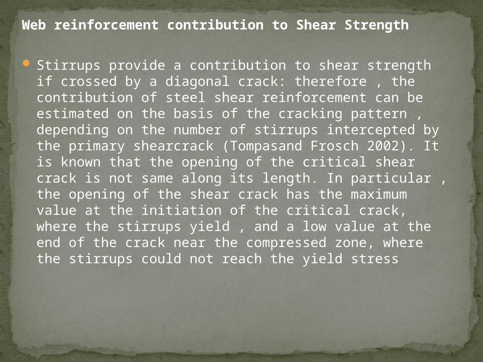
Web reinforcement contribution to Shear Strength
Stirrups provide a contribution to shear strength if crossed by a diagonal crack: therefore , the contribution of steel shear reinforcement can be estimated on the basis of the cracking pattern , depending on the number of stirrups intercepted by the primary shearcrack (Tompasand Frosch 2002). It is known that the opening of the critical shear crack is not same along its length. In particular , the opening of the shear crack has the maximum value at the initiation of the critical crack, where the stirrups yield , and a low value at the end of the crack near the compressed zone, where the stirrups could not reach the yield stress
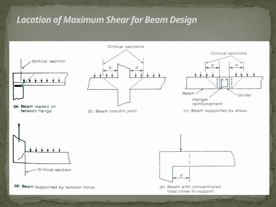
Location of Maximum Shear for Beam Design
Compression from support at bottom of beam tends to close crack at support
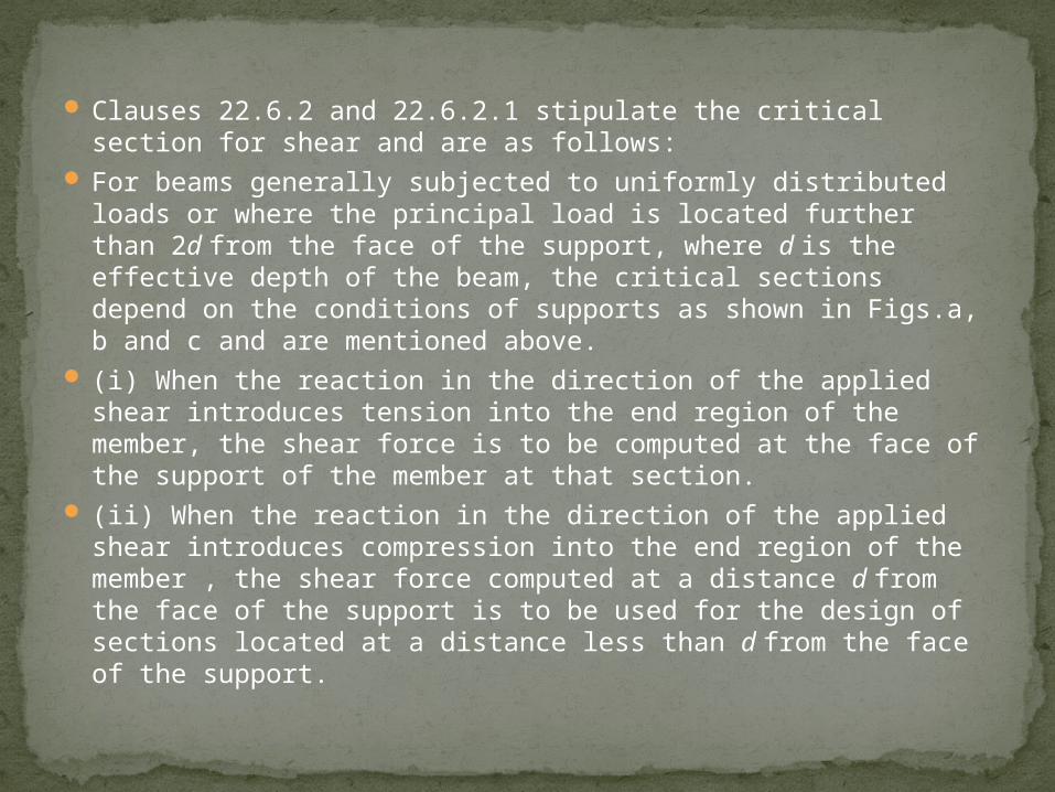
Clauses 22.6.2 and 22.6.2.1 stipulate the critical section for shear and are as follows:
For beams generally subjected to uniformly distributed loads or where the principal load is located further than 2d from the face of the support, where d is the effective depth of the beam, the critical sections depend on the conditions of supports as shown in Figs.a, b and c and are mentioned above.
(i) When the reaction in the direction of the applied shear introduces tension into the end region of the member, the shear force is to be computed at the face of the support of the member at that section.
(ii) When the reaction in the direction of the applied shear introduces compression into the end region of the member , the shear force computed at a distance d from the face of the support is to be used for the design of sections located at a distance less than d from the face of the support.
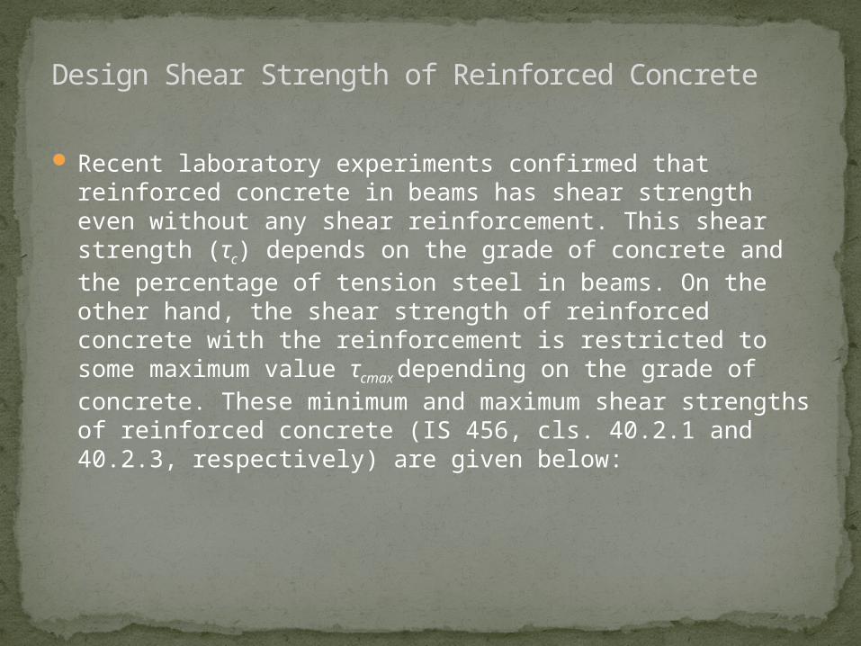
Recent laboratory experiments confirmed that reinforced concrete in beams has shear strength even without any shear reinforcement. This shear strength (τc) depends on the grade of concrete and the percentage of tension steel in beams. On the other hand, the shear strength of reinforced concrete with the reinforcement is restricted to some maximum value τcmax depending on the grade of concrete. These minimum and maximum shear strengths of reinforced concrete (IS 456, cls. 40.2.1 and 40.2.3, respectively) are given below:
Design Shear Strength of Reinforced Concrete
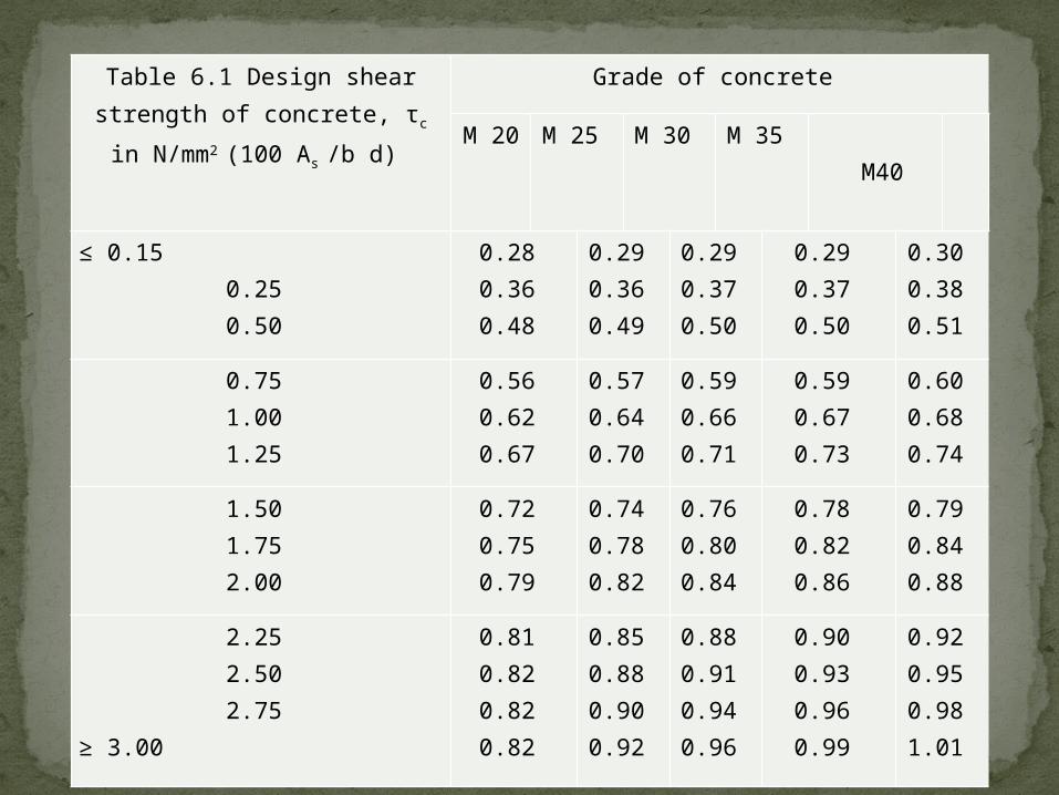
Table 6.1 Design shear strength of concrete, τc in
N/mm2 (100 As /b d)
Grade of concrete
M 20 M 25 M 30 M 35 M40
≤ 0.15 0.25 0.50
0.28 0.36 0.48
0.29 0.36 0.49
0.29 0.37 0.50
0.29 0.37 0.50
0.30 0.38 0.51
0.75 1.00 1.25
0.56 0.62 0.67
0.57 0.64 0.70
0.59 0.66 0.71
0.59 0.67 0.73
0.60 0.68 0.74
1.50 1.75 2.00
0.72 0.75 0.79
0.74 0.78 0.82
0.76 0.80 0.84
0.78 0.82 0.86
0.79 0.84 0.88
2.25 2.50 2.75
≥ 3.00
0.81 0.82 0.82 0.82
0.85 0.88 0.90 0.92
0.88 0.91 0.94 0.96
0.90 0.93 0.96 0.99
0.92 0.95 0.98 1.01
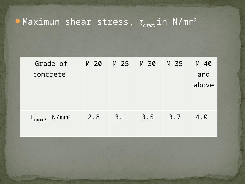
Maximum shear stress, τcmax in N/mm2
Grade of concrete
M 20 M 25 M 30 M 35 M 40 and
above
Τcmax, N/mm2 2.8 3.1 3.5 3.7 4.0
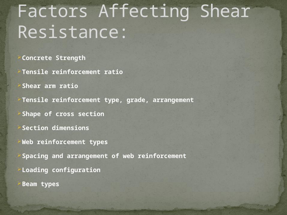
Concrete Strength
Tensile reinforcement ratio
Shear arm ratio
Tensile reinforcement type, grade, arrangement
Shape of cross section
Section dimensions
Web reinforcement types
Spacing and arrangement of web reinforcement
Loading configuration
Beam types
Factors Affecting Shear Resistance:
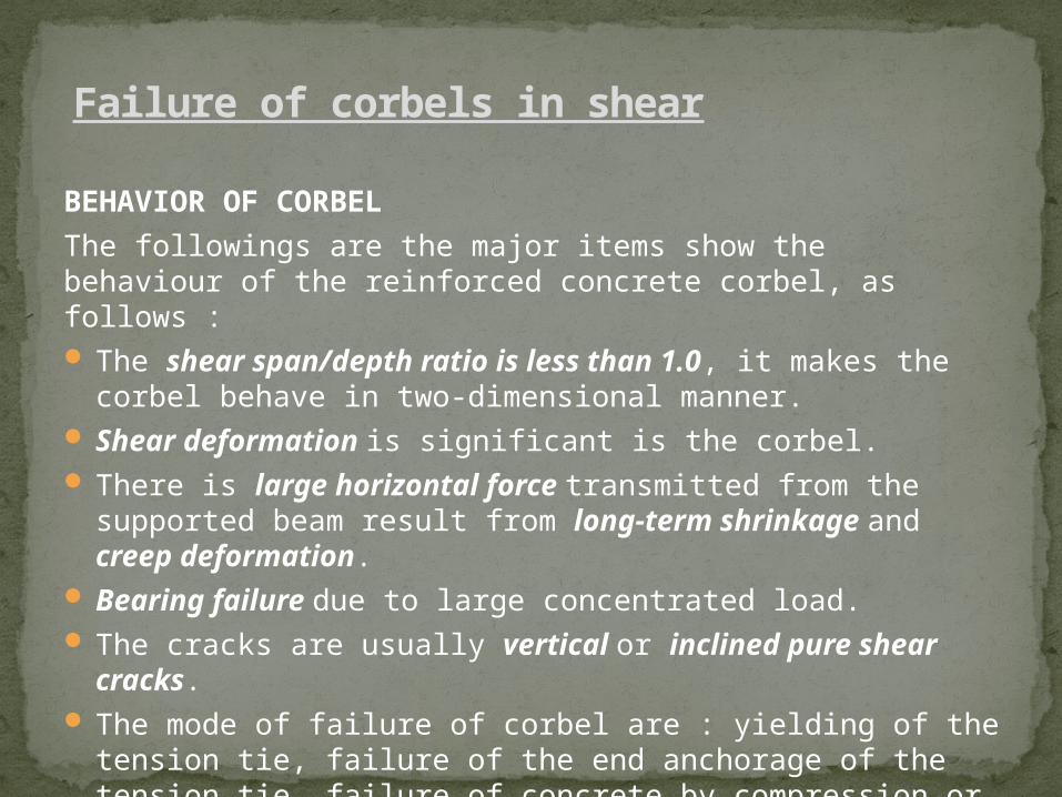
BEHAVIOR OF CORBEL
The followings are the major items show the behaviour of the reinforced concrete corbel, as follows : The shear span/depth ratio is less than 1.0, it makes
the corbel behave in two-dimensional manner. Shear deformation is significant is the corbel. There is large horizontal force transmitted from the
supported beam result from long-term shrinkage and creep deformation.
Bearing failure due to large concentrated load. The cracks are usually vertical or inclined pure shear
cracks. The mode of failure of corbel are : yielding of the tension
tie, failure of the end anchorage of the tension tie, failure of concrete by compression or shearing and bearing failure.
Failure of corbels in shear
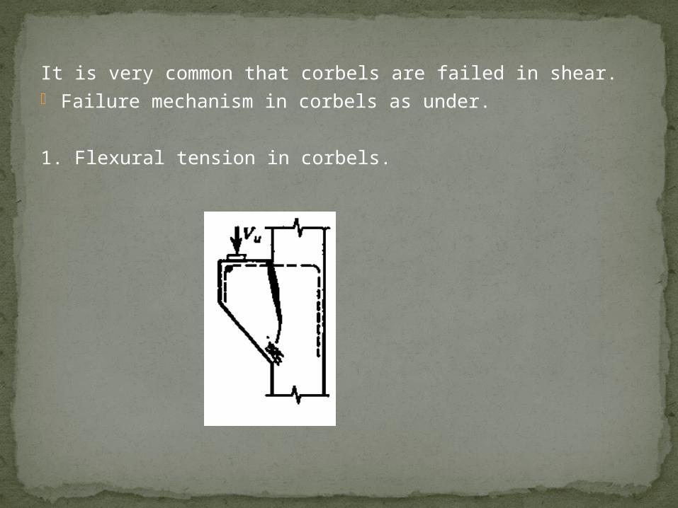
It is very common that corbels are failed in shear. Failure mechanism in corbels as under.
1. Flexural tension in corbels.
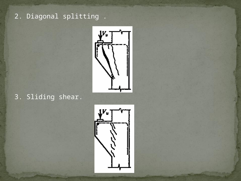
2. Diagonal splitting .
3. Sliding shear.
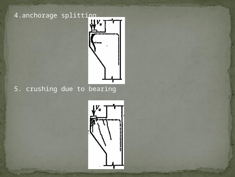
4.anchorage splitting.
5. crushing due to bearing
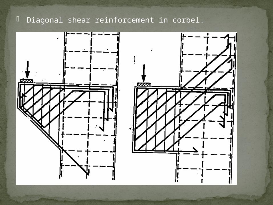
Diagonal shear reinforcement in corbel.
Shear reinforcement should be provided in the form
of horizontal links distributed in the upper two-third
of the effective depth of root of the corbel; this
reinforcement should be not less than one-half of the
area of the main tension reinforcement and should be
adequately anchored.
IS CLAUSE FOR PROVISION OF SHEAR REINFORCEMENT IN CORBELS
Case study shear failure
Two warehouse roofs at Air Force Bases in Ohio and Georgia cracked and collapsed under combined load, shrinkage, and thermal effects in 1955 and 1956. 122 m (400 ft) lengths of reinforced concrete roof girders functioned as single units because of defective expansion joints. Other warehouses, built to the same plans, survived because separation between adjacent two-hundred-foot bays was maintained by functioning joints. These failures led to more stringent shear reinforcing steel requirements in subsequent editions of the ACI Building Code. In the warehouse structures, the concrete alone, with no stirrups, was expected to carry the shear forces, and the members had no shear capacity once they cracked (McKaig 1962, Feld and Carper, 1997).
Wilkins Air Force Depot, 1955
At the Wilkins Air Force Depot in Shelby , Ohio , about 370 m2 (4,000 ft2) of the roof collapsed suddenly on August 17, 1955. At the time of collapse, there were no loads other than the self-weight of the roof (Feld 1964, p. 25).
The Air Materiel Command (AMC) built warehouses to a common design at many Air Force bases and depots. The original design was developed in April 1952, with a modification to reinforcement made in March 1954. The Ohio warehouse had been built to the original 1952 design. It was a six-span rigid frame building, 122 m (400 ft) wide and 610 m (2,000 ft) long. The haunched rigid frames each had six 20 m (67 ft) spans, and were spaced approximately 10 m (33 ft) on center.
The concrete for each frame was placed continuously in a single working day. Vertical steel plate construction joints were set at the center of each span before concrete placement, but they may not have been effective (Feld 1964, p. 25).
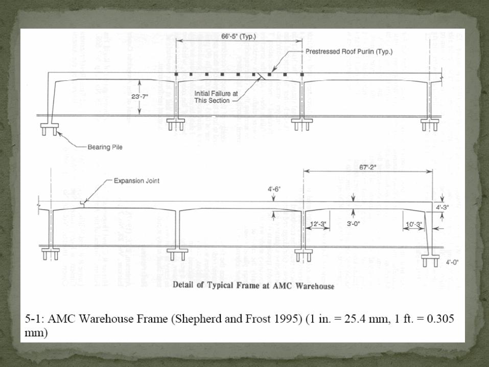
Severe cracking had been observed two weeks before the collapse, so the girder had been supported by temporary shoring. The cracks occurred about 0.45 m (1 ½ ft) past the end of the cutoff of the top negative reinforcement over the columns (Feld 1964, pp. 26 – 27). A typical AMC warehouse frame is shown below.
A second warehouse roof collapse took place at Robins Air Force Base near Macon , Georgia , early on the morning of September 5, 1956. This warehouse had been built to the revised design. The revision added top bars and nominal stirrups, at a volume of about 0.06 %, for the length of the frames. This collapse included two adjacent girders and about 560 m2 (6,000 ft2) of the roof. Before the collapse occurred, cracks in the concrete girders that reached 13 mm (½ in) in width had been observed. Feld (1964, p. 25) suggests “It seems that the extent of shrinkage and resulting axial tensions may be somewhat related to the speed of concreting or to the extent of each separate placement.”
In both cases, the design, materials, and workmanship were up to the codes and standards of the day. However, the failures had still occurred. Feld (1964, p 27) believed that “failure took place by a combination of diagonal tension (shear) due to dead load and axial tension due to shrinkage and temperature change. Circumstantial evidence suggested that high friction forces were developed in the expansion joint consisting of one steel plate sliding on another; some plates showed no indication of relative displacement since their installation.” In other words, the expansion joints locked and did not function to relieve stress.
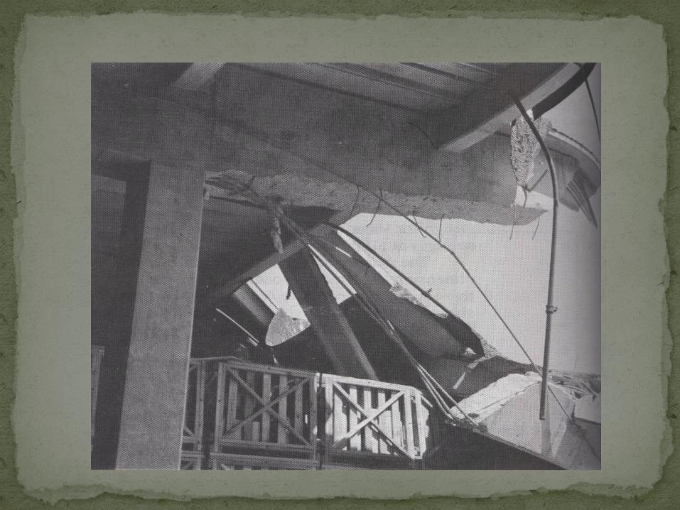
Building collapsed while under construction at 2000 Commonwealth Avenue, Boston, Massachusetts
On January 25, 1971, two thirds of a 16-story apartment building collapsed while under construction at 2000 Commonwealth Avenue, Boston, Massachusetts. Four workers died after a failure on the roof instigated a progressive collapse all the way to the basement, where the men were found. Fortunately, the collapse occurred slowly enough for most of the other workers to run to safety. The surviving workers' descriptions of the failure provide a textbook definition of punching shear. Low concrete strength due to inadequate protection against cold weather contributed to low punching shear strength of the flat slab. Inspection, quality control, planning, and supervision were for all practical purposes absent from the project.
The high-rise apartment building was made of cast-in-place reinforced concrete flat slab construction with a central elevator shaft. was designed to be sixteen stories with a mechanical room above a five-foot crawl space on the roof. The structure also had two levels of underground parking. A swimming pool, ancillary spaces and one apartment were located on the first floor and one hundred thirty two apartments were on the second through sixteenth floors.
Construction began on the site late in the fall of 1969. Excavation had been partially started a few years earlier. Most of the work was subcontracted to area specialists. Only one representative from the General Contractor was on site during construction. At the time of collapse, construction was nearing completion. Brickwork was completed up to the sixteenth floor and the building was mostly enclosed from the second to fifteenth floors. Plumbing, heating and ventilating systems were being installed throughout various parts of the building. It is estimated that one hundred men were working in or around the building at the time of failure (Granger et al. 1971).
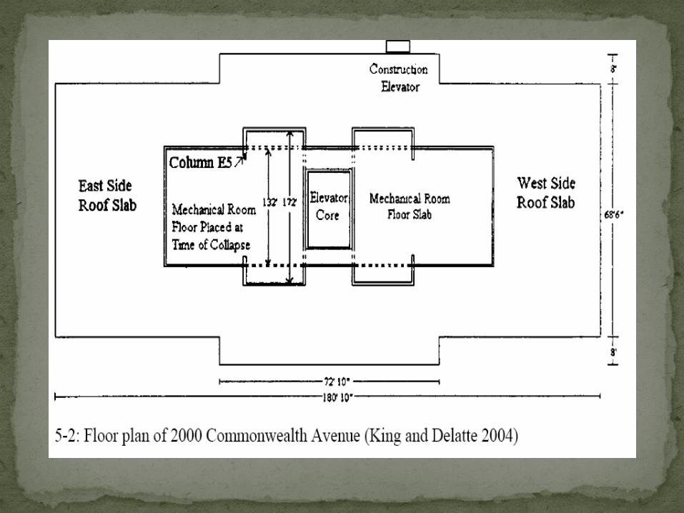
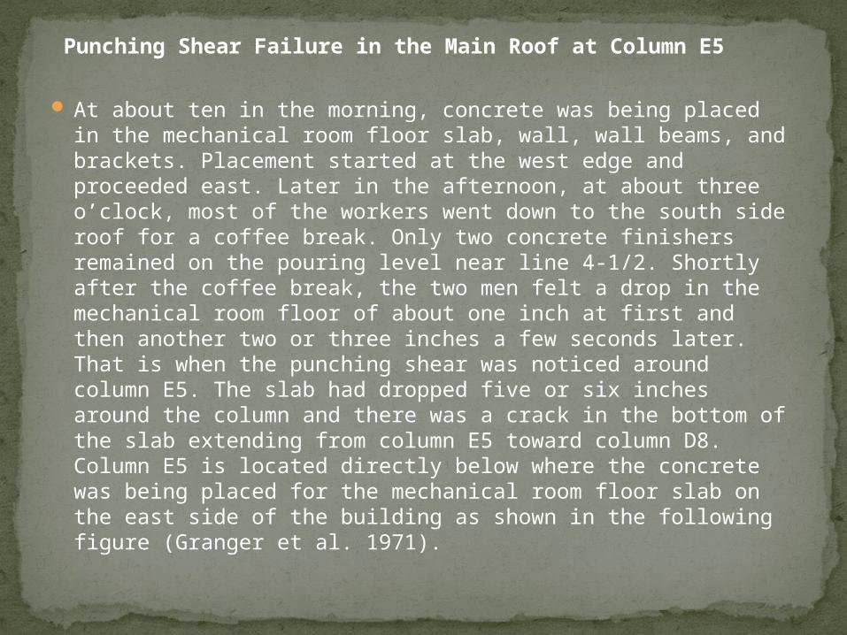
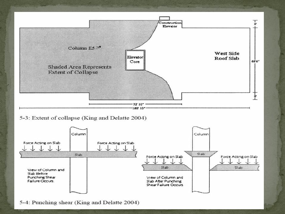
Punching Shear Failure in the Main Roof at Column E5
At about ten in the morning, concrete was being placed in the mechanical room floor slab, wall, wall beams, and brackets. Placement started at the west edge and proceeded east. Later in the afternoon, at about three o’clock, most of the workers went down to the south side roof for a coffee break. Only two concrete finishers remained on the pouring level near line 4-1/2. Shortly after the coffee break, the two men felt a drop in the mechanical room floor of about one inch at first and then another two or three inches a few seconds later. That is when the punching shear was noticed around column E5. The slab had dropped five or six inches around the column and there was a crack in the bottom of the slab extending from column E5 toward column D8. Column E5 is located directly below where the concrete was being placed for the mechanical room floor slab on the east side of the building as shown in the following figure (Granger et al. 1971).
A week after the collapse, Engineering News Record reported that there were three possible causes of structural failure under investigation: formwork for the penthouse floor slab collapsed onto the roof, a heavy piece of equipment fell from a crane and started the progressive collapse, or concrete placed during previous cold days had failed (ENR, February 4, 1971). However, after an extensive investigation, the mayor's commission concluded that there were many design and construction flaws that attributed to the collapse. The committee determined that punching shear failure at column E5 triggered the initial collapse. This type of failure is caused by unbalanced moments transferred between the column and flat-plate (Megally and Ghali 2000) and was a result of non-conformities to the design documents.
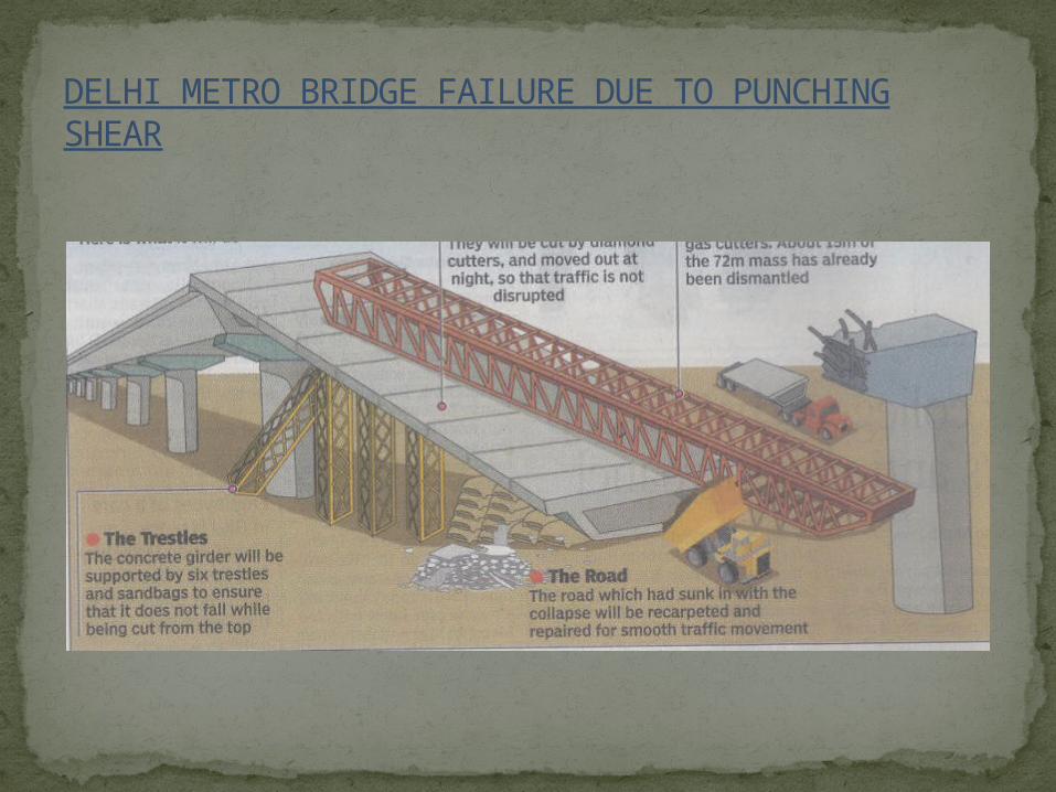
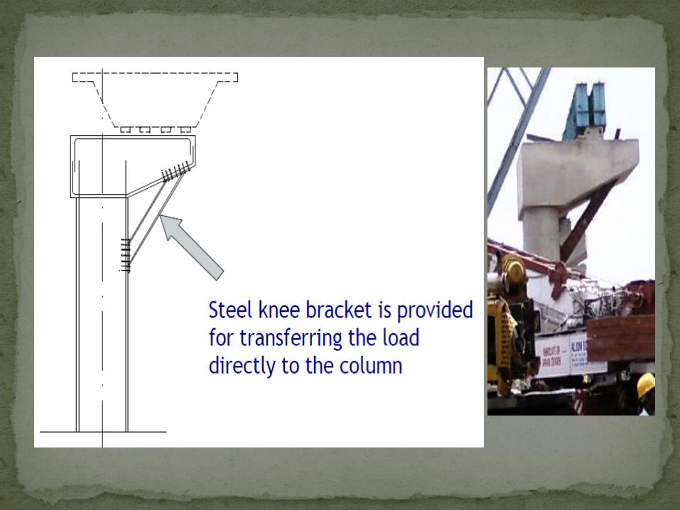
DELHI METRO BRIDGE FAILURE DUE TO PUNCHING SHEAR
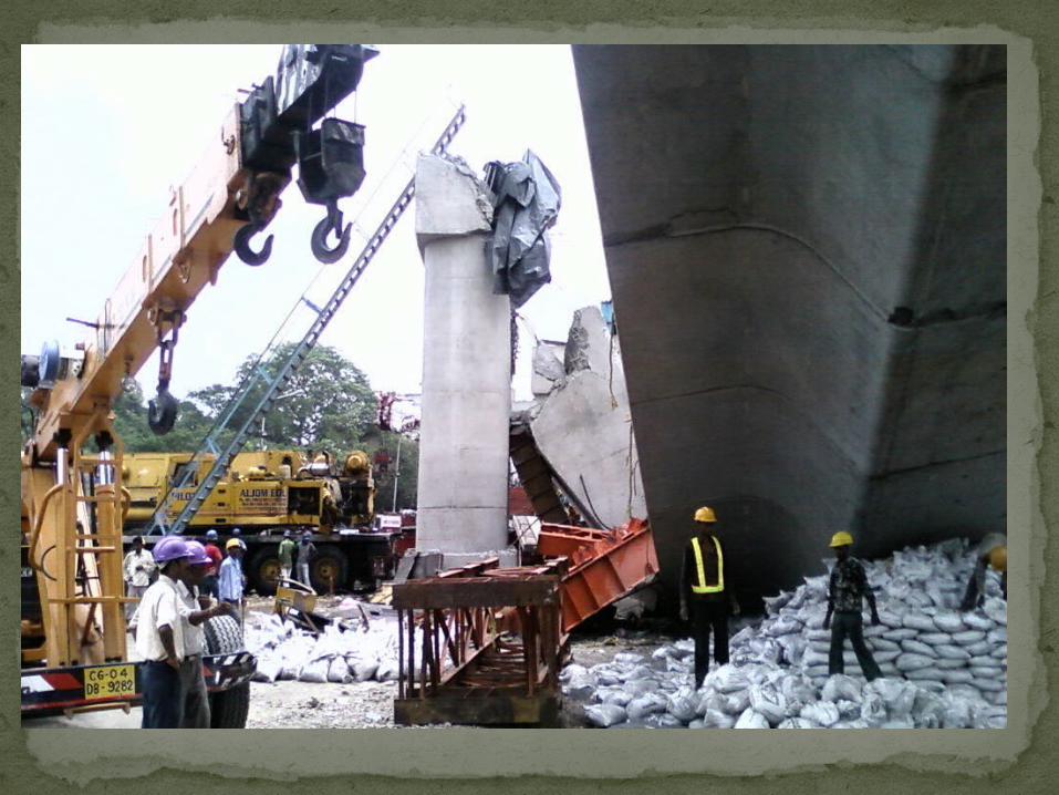
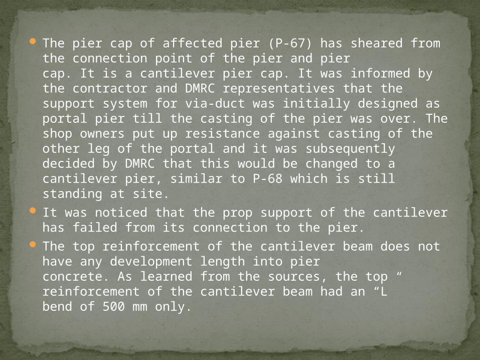
The pier cap of affected pier (P-67) has sheared from the connection point of the pier and piercap. It is a cantilever pier cap. It was informed by the contractor and DMRC representatives that the support system for via-duct was initially designed as portal pier till the casting of the pier was over. The shop owners put up resistance against casting of the other leg of the portal and it was subsequently decided by DMRC that this would be changed to a cantilever pier, similar to P-68 which is still standing at site.
It was noticed that the prop support of the cantilever has failed from its connection to the pier.
The top reinforcement of the cantilever beam does not have any development length into pierconcrete. As learned from the sources, the top reinforcement of the cantilever beam had an “L”bend of 500 mm only.

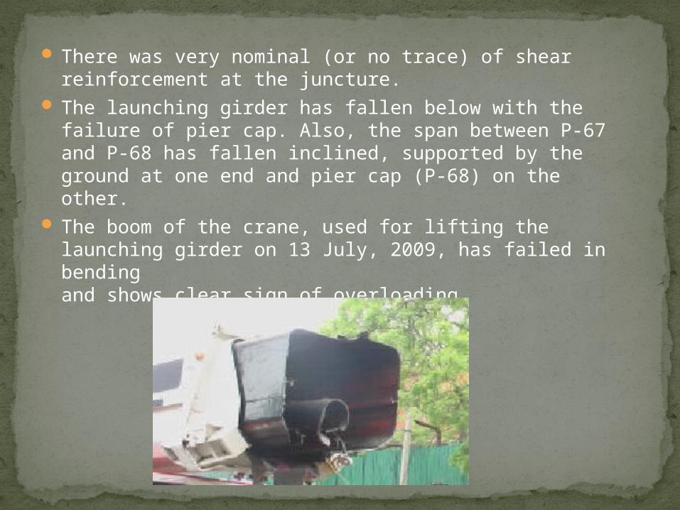
There was very nominal (or no trace) of shear reinforcement at the juncture.
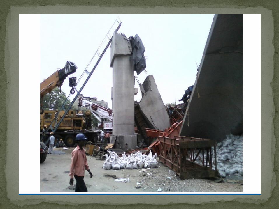
The launching girder has fallen below with the failure of pier cap. Also, the span between P-67and P-68 has fallen inclined, supported by the ground at one end and pier cap (P-68) on theother.
The boom of the crane, used for lifting the launching girder on 13 July, 2009, has failed in bendingand shows clear sign of overloading.
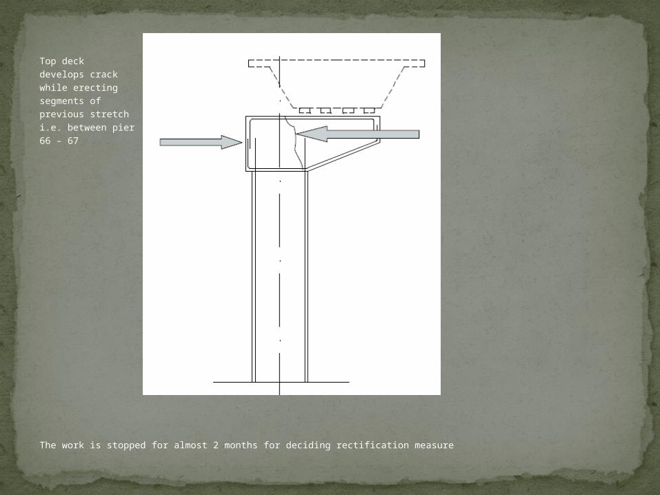
Top deckdevelops crackwhile erectingsegments ofprevious stretchi.e. between pier66 – 67 Probable Cause – insufficient lap of deck top tension rebars with pier’s projected rebars. The cantilevered deck shows signs of failure as crack.
The work is stopped for almost 2 months for deciding rectification measure
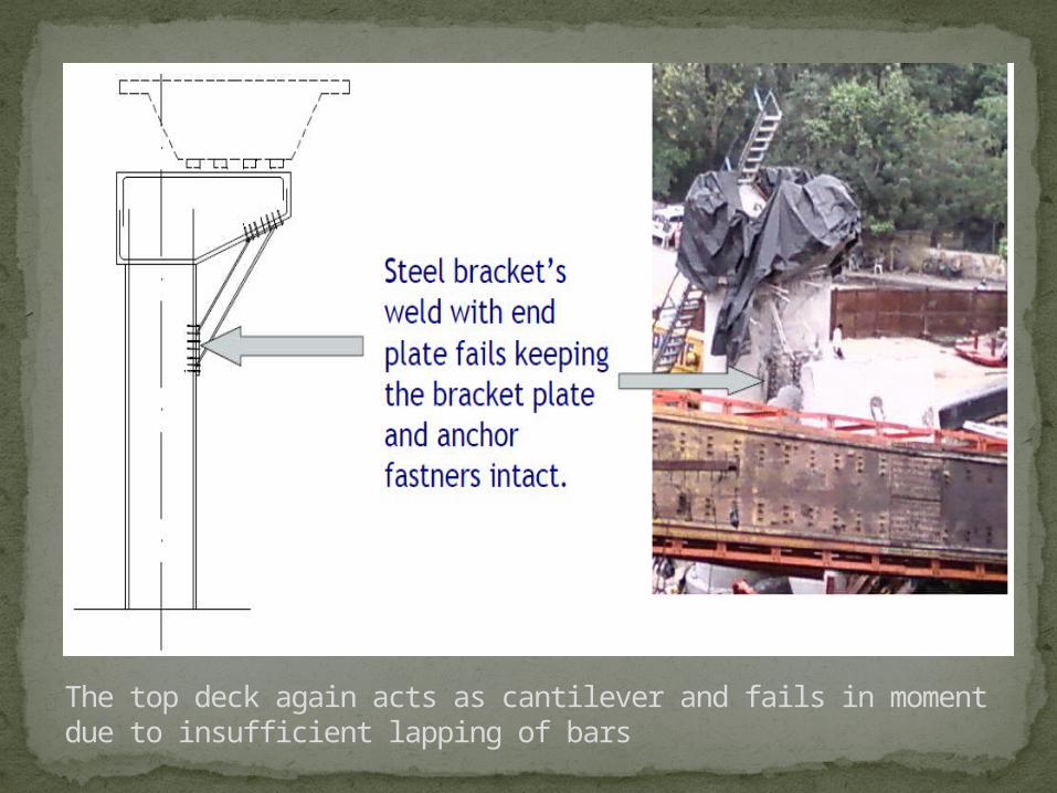
The top deck again acts as cantilever and fails in moment due to insufficient lapping of bars
What it taught us?
a. Structural designs should be proof checked by experienced structural engineer.
b. Once failure observed, structure should be as far as practicable abandoned and new structure should be built up
c. More emphasis should be given on detailing of reinforcement to cater for connections and behaviour of the structural components.
d. Any make-shift arrangement to save a failed structure should be avoided.
e. Reinforcement detailing in corbels, deep beams, cantilever structures should be checked as per the provisions of more than one type of Standards (both IS & BS should be followed).
f. Adequately experienced Engineer / Forman should be deployed for erection works.
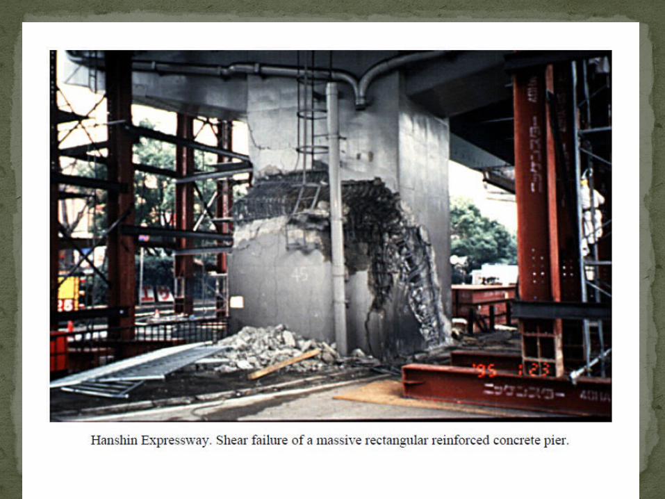
FEW PICTURES OF FAILURES DUE TO SHEAR
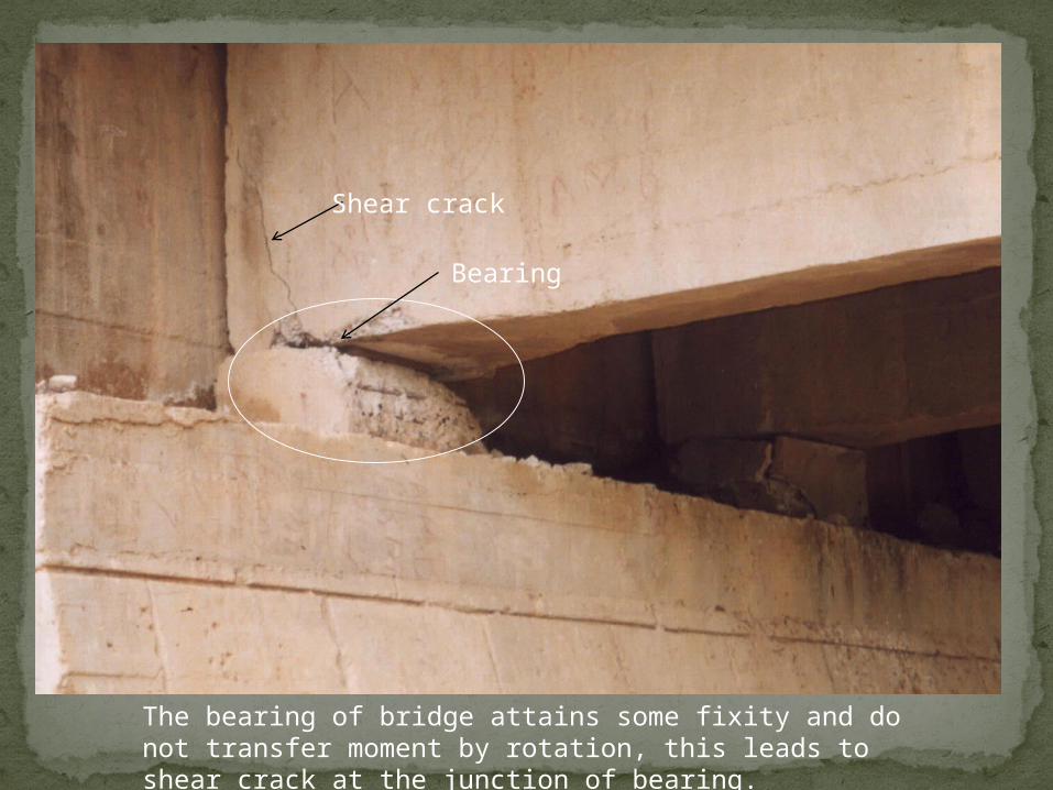
The bearing of bridge attains some fixity and do not transfer moment by rotation, this leads to shear crack at the junction of bearing.
Shear crack
Bearing
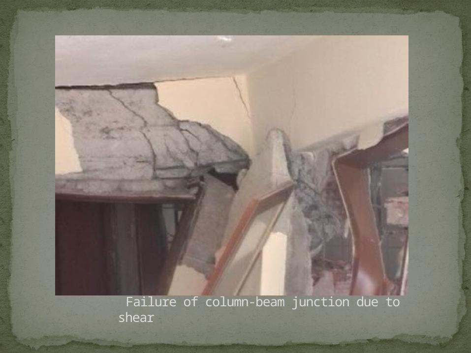
Failure of column-beam junction due to shear
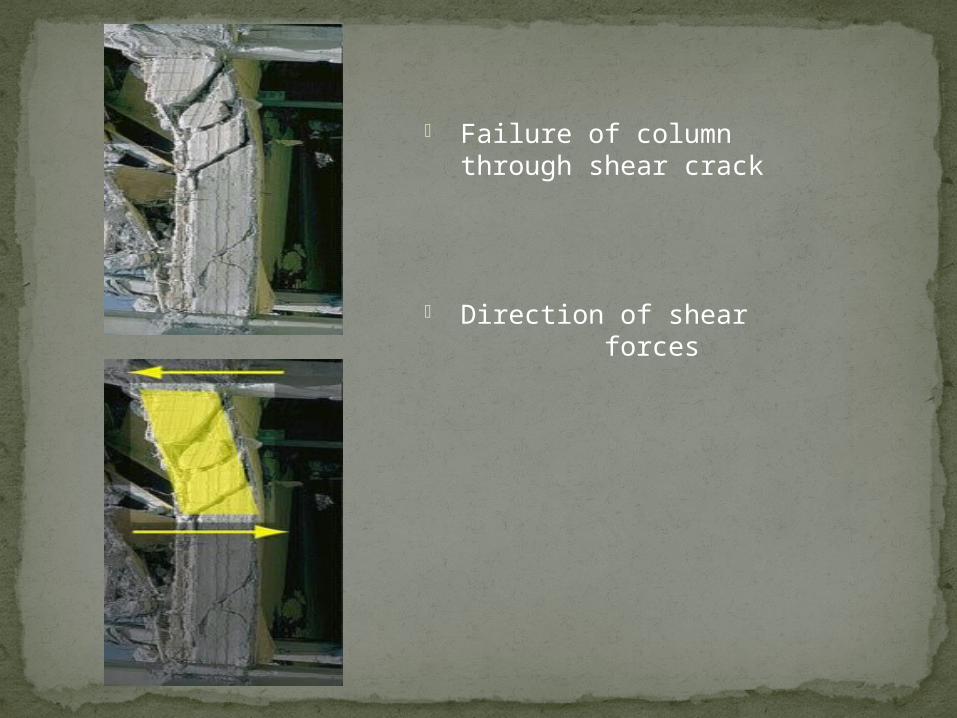
Failure of column through shear crack
Direction of shear forces
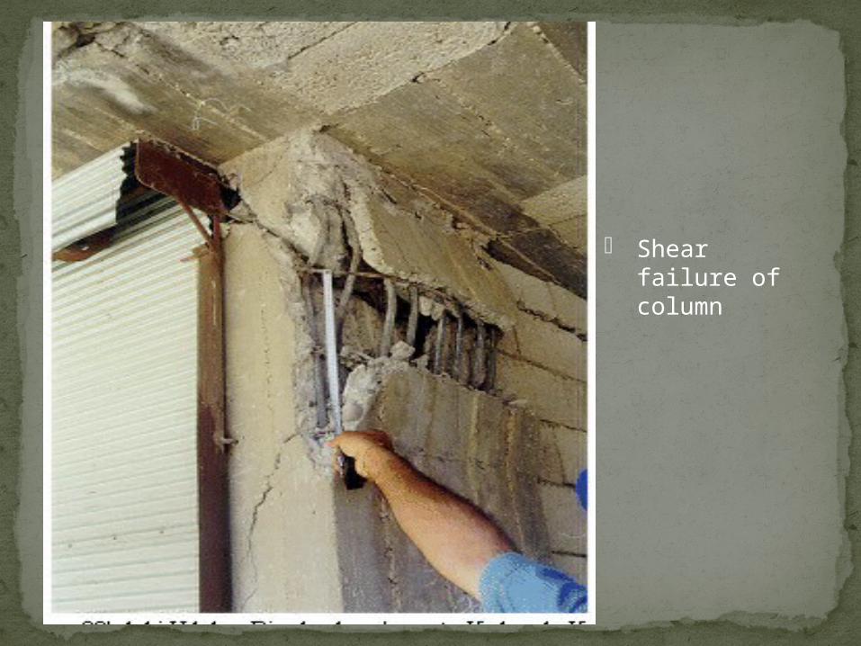
Shear failure of column
Beyond failure- forensic case studies for civil engineers By Norbert J. Delatte
Construction failure By Jacob Feld- Kenneth L. Carper Paper by dileep kumar (P.G M.Tech Lecturer, Dept. of Civil Engg.
Govt. Engg. College, Palakkad. ) on “SHEAR STRENGTH OF R.C.C BEAMS WITHOUT WEB REINFORCEMENT”
www.nptel.iitm.in Shear study by : (Dr. Amlan K Sengupta and Prof. Devdas Menon)
http://matdl.org/failurecases (Case studies) http://jan.ucc.nau.edu Pictures from (www.google.com\images )
Bibliography

Related Documents