TECHNICAL BULLETIN NO. 182 APRIL, 1930 UNITED STATES DEPARTMENT OF AGRICULTURE WASHINGTON, D. C. FACTORS AFFECTING THE MECHANICAL APPLICATION OF FERTILIZERS TO THE SOIL By ARNON L. MEHRING, Associate Chemist, Fertilizer and Fixed 'Nitrogen Inves- tigations, Bureau of Chemistry and Soils, and GLENN A. CUMINGS, Agricultural Engineer, Division of Agricultural Engineering, Bureau of Fu'blic Roads'^ CONTENTS Page Introduction 1 Earl y mechanical distributors 2 Purpose of the investigation 5 Preliminar y work — 5 Description of experimental apparatus, mate- terials, and methods 8 A ir-conditioning plant >i Fertilizers and distributors selected.. 11 Experimental methods. 15 Factors affecting the drillability of fertilizers,. 17 Weather "17 Hygroscopicity - 22 State of subdivision.. 24 Heterogeneity 32 Specific gravity 33 Friction between particles 35 Conditioners 40 Distributors, their construction and opera- tion 42 Types of distributors 42 Types of fertilizers used in the study of dis- tributors 42 Experimental procedure 44 Distributor No. 1, grain-drill attachment-. 47 Distributor No. 2, grain-drill attachment. 51 Distributor No. 3, potato-planter attach- ment ,-^ 54 Page Distributors, their construction and opera- tion—Continued. Distributor No. 4, potato-planter attach- ment 56 ]^istributor No. 5, potato-planter attach- ment 58 Distributor No. 6, corn-plan ter attachment- 60 Distributor No. 7, broadcast or 3-row dis- tributor- — 62 Distributor No. 8, single-row distributor... 63 Distributor No. 9, single-row distributor... 66 ])istributor No. 10, single-row distributor.. 67 European types of distributors — 70 Factors affecting the operation of distributors 72 Depth of fertilizer in the hopper 72 Inclination of distributor. 75 Variation in distributing units.. 77 Unrestricted flow of fertilizer through the distributing mechanism 80 Use of agitators,. 81 Feed-wheel speed... 82 Positive action of the distributing mecha- nism. 83 Uniformity of distribution 84 General results and recommendations 87 Conclusions 93 Literature cited__ 94 INTRODUCTION Although marl, saltpeter, animal excrements, and wood ashes had been used for many centuries to increase crop yields, the fertilizer industry may be said to have begun with the introduction of super- phosi^hate in 1842. Within the following 2Ó years Chilean nitrate, guano, sulphate of ammonia, fish scrap, and the German potash salts came into general use as fertilizers. At first these fertilizer materials were applied singly to crops, and this is still the usual practice in Europe. About 1860, a mixture ^ R. B. Gray, senior agricultural engineer, and M. A. R. Kelley, associate agricultural engineer, represented the Bureau of I'ublic Roads during the early stages of this study. The writers wish to express their indebtedness to W. H. Ross, senior chemist in charge of concentrated-fertilizer investigations, for valuable suggestions and kindly assistance in connection with this study. Ö8734—30 1

Welcome message from author
This document is posted to help you gain knowledge. Please leave a comment to let me know what you think about it! Share it to your friends and learn new things together.
Transcript

TECHNICAL BULLETIN NO. 182 APRIL, 1930
UNITED STATES DEPARTMENT OF AGRICULTURE
WASHINGTON, D. C.
FACTORS AFFECTING THE MECHANICAL APPLICATION OF FERTILIZERS
TO THE SOIL By ARNON L. MEHRING, Associate Chemist, Fertilizer and Fixed 'Nitrogen Inves-
tigations, Bureau of Chemistry and Soils, and GLENN A. CUMINGS, Agricultural Engineer, Division of Agricultural Engineering, Bureau of Fu'blic Roads'^
CONTENTS
Page Introduction 1
Earl y mechanical distributors 2 Purpose of the investigation 5 Preliminar y work — 5 Description of experimental apparatus, mate-
terials, and methods 8 A ir-conditioning plant >i Fertilizers and distributors selected.. 11 Experimental methods. 15
Factors affecting the drillability of fertilizers,. 17 Weather "17 Hygroscopicity - 22 State of subdivision.. 24 Heterogeneity 32 Specific gravity 33 Friction between particles 35 Conditioners 40
Distributors, their construction and opera- tion 42
Types of distributors 42 Types of fertilizers used in the study of dis-
tributors 42 Experimental procedure 44 Distributor No. 1, grain-drill attachment-. 47 Distributor No. 2, grain-drill attachment. 51 Distributor No. 3, potato-planter attach-
ment ,-^ 54
Page Distributors, their construction and opera-
tion—Continued. Distributor No. 4, potato-planter attach-
ment 56 ]^istributor No. 5, potato-planter attach-
ment 58 Distributor No. 6, corn-plan ter attachment- 60 Distributor No. 7, broadcast or 3-row dis-
tributor- — 62 Distributor No. 8, single-row distributor... 63 Distributor No. 9, single-row distributor... 66 ])istributor No. 10, single-row distributor.. 67 European types of distributors — 70
Factors affecting the operation of distributors 72 Depth of fertilizer in the hopper 72 Inclination of distributor. 75 Variation in distributing units.. 77 Unrestricted flow of fertilizer through the
distributing mechanism 80 Use of agitators,. 81 Feed-wheel speed... 82 Positive action of the distributing mecha-
nism. 83 Uniformity of distribution 84 General results and recommendations 87 Conclusions 93 Literature cited__ 94
INTRODUCTION
Although marl, saltpeter, animal excrements, and wood ashes had been used for many centuries to increase crop yields, the fertilizer industry may be said to have begun with the introduction of super- phosi^hate in 1842. Within the following 2Ó years Chilean nitrate, guano, sulphate of ammonia, fish scrap, and the German potash salts came into general use as fertilizers.
At first these fertilizer materials were applied singly to crops, and this is still the usual practice in Europe. About 1860, a mixture
^ R. B. Gray, senior agricultural engineer, and M. A. R. Kelley, associate agricultural engineer, represented the Bureau of I'ublic Roads during the early stages of this study. The writers wish to express their indebtedness to W. H. Ross, senior chemist in charge of concentrated-fertilizer investigations, for valuable suggestions and kindly assistance in connection with this study.
Ö8734—30 1

2 TECHNICAL BULLETIN 182, U. S. DEPT. OF AGIÎICULTUEE
known as ammoniated phosphate and consisting of guano and super- phosphate was first sold. This met with such success that complete mixtures were soon offered, and by 1880 their use was widespread. For many years these mixed fertiiizers were prepared from guano, cottonseed "meal, bone dust, hardwood ashes, and superphos])hate, with small additions of Chilean nitrate, ammonium sulphate, and potash salts. The average plant-food content was about 2 per cent ammonia, 8 per cent phosphoric acid, and 2 per cent potash.
EARLY MECHANICAL DISTRIBUTORS
Machines for spreading lime. i)laKter, ashes, and giuino were in- vented before connneruial fertilizei-s were develo])ed. The first patent on such an implement was granted about 1830 by the United States Patent Office. A periodical (i)^ in 1838 mentions Wells's lime
FlorRK 1.—So.vinmir's broadcast lime and K"ano sower
sower, which it was claimed was caijable of distributing " from 2 to 500 bushels "' of lime. iiiiU'l. ashes, etc., ])er acre.
Seymour'.s broadcast lime and guano sower {'.¿), patented in 1845, was first ofl'ered to the public about 1848. This implement is illus- trated in Figure 1. In advertisements the claim was made for years that the niaclune would dust evenly every square inch of soil with an application as snuill as (me-half I)ushel of plaster, lime, or bone dust (o the acre, and that the (juantity sown could be regulated to within I pint per acre. Cooper's lime si)reader ' (fig. 2) and Fawkes's lime and guano spreader ^ were placed on the market a few years later.
These early distributors were broadcasters of simple construction. Usually the hopper was oblong, with an adjustable slit running the
' Italic numbers in p-lrontbcscs refer to Literature cited p ft4 ■COOPER, L. IMPROVEMENT m SPREADING LIME AND .MANIRé. (II. S. I'ntent No "J339
Oct. 19. 1852.) U. .S. Patents, v. 100. 1852-53 ..lî!?^."^^' •'■ ^- IMPKOVEMEXT IN MANURE AND LIME SPBEADEH.S (U. S. Patent No. 11602, Aug. 20, 1854.) U. S. Patents, v. 114. 1854.
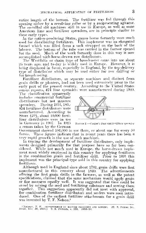
MECHANICAL APPLICATION OF FERTILIZERS 8
entire length of the bottom. The fertilizer was fed through this opening either by a revolving roller or by a reciprocating agitator. The so-called slit machines still in use in Europe, as well as some American lime and fertilizer spreaders, aie in principle similar to tliese earlv types.
In the cotton-producing States, guano horns formerly were much used for distributing fertilizers. This implement was an elongated funnel which was filled from a sack strapped on tlie back of the laborer. The bottom of the tube was carried in the furrow opened for the seed. Much of the work formerly done in this way is now accomplished with horse-drawn row distributors.
'Jlie Westfalia or chain type of broadcaster came into use about 25 years ago. and to-day is widely used in Europe. However, it is being disjdaced in favor, especially in England, by the top-delivery type of distribuior which may be used either for row drilling or for broadcasting.
Eertilizer distributors, as separate machines and distinct from grain drills or planters, had not been used extensively prior to the early part of the present century. According to the United States census reports, 474 lime spreaders were manufactiu'ed during 1900. The classification apparently includes connnercial fertilizer distributoi's but not manure spreaders. Dni-ing 1914, 180,- 854 fertilizer distributors were manufactui'ed. According to Storz (20), about 10,000 ferti- lizer distributors were in use in Germany in 1907. In 1925 FIGUHEÍ.—Coorer's llme ano fertilizer siircailrr a census taken by the (ierman (iovernmont showed 104,000 in use there, or about one for every 50 farnis. These figures indicate that in recent years there has been a verj' rapid growth in the use of such machines.
In tracing the development of fertilizer distributors, only imple- ments designed primarily for that purpose have so far been con- sidered. While not much used in Elurope. the horse-drawn imple- ment most widely employed in this country for applying fertilizers is the combination grain and fertilizer drill. Prior to 189:5 this implement was the principal type sold in this country for applying fertilizers.
Although used in England since about 1782, grain drills were first manufactured in this country about 1840. The advertisements offering the first grain drills to the farmers, as well as the patent specifications, claimed that the same mechanism would apply grain or fine manures equally well. It was suggested that time could be saved by mixing the seed and fertilizing substance and sowing them together. This suggestion apparently did not meet with approval, for combination fertilizer distributors and seeders were soon intro- duced. One of the earliest fertilizer attachments for a grain drill Avas invented by T. F. Nelson.^
= NELSON, T. F. IMPIIOïEMKNT IN MANUBE CRUSHERS AND SOWERS. (Ü. S. I'atcnt No 10.325, Uoc. 20, 1853.) U. S. Patents, v. 111. 1853-54.

4 TECHNICAL BULLETIN 3 8 2, U. S. DEPT. OF AGEICULTUEE
Seymour's combination grain and fertilizer drill was first offered for sale in 1854. Within a year or two thereafter practically all makes of grain drills were obtainable with fertilizer attachments. The Bickford and Hoffman " combination grain and fertilizer drill (fig. 3) soon became a favorite, and for many years was very popular.
The star-wheel or wizard type of feed for use in grain-drdl attach- ments was invented in 1883, and the first model was almost identical with the design still commonly used.
Probably the first combination planter and fertilizer distributor was devised in 1838 by White (¡¿2). (Fig. 4.) It was rather compli- cated and never was commercialized. The earliest combination corn
FiGUEK 3.—The Bickford and HoSiuan grain drill and fertilizer distributor
planter and fertilizer distributor placed on the market probably was Billings's machine (13), which is illustrated in Figure 5.
Potato planters with fertilizer attachments were first used about 1880. One of the first was True's (3), shown in Figure G.
In 1919 Hurd {J£) made a survey of the products of the leading manufacturers of farm implements and estimated that 27 per cent of the corn planters, 35 per cent of the potato planters, and 29 per cent of the grain drills sold in that year had fertilizer attachments. Practically no cultivators with such attachments were sold in that year.
At present many different types of distributors are in use, and most seeders and planters, as well as several makes of cultivators and
•BicKrORD, L. iMrRovïMïNT IN MACHINES FOB sowiNO rKBTiUEiES. (U S Patent No. 21181. Aus. 17, 1858.) U. S. Patents v. 137. 1858.

MECHANICAL APPLICATION OF FEETILIZERS
transplanting machines, may be purchased equipped with fertilizer attachments. Considering the sales of several of the leading manu- facturers in 1928, the percentages of machines now sold with ferti- lizer attachments are estimated by classes as follows : Corn planters, 37 per cent; cotton planters, 9 per cent; potato planters, 60 per cent; grain and beet drills, 40 per cent ; and cultivators, 4 per cent. Sev- eral thousand patents on fertilizer-distributing machines have been issued by the United States Patent Office. Allen (5) describes and illustrates most of those granted up to the end of 1885.
The implements now employed in this country were designed to apply the low-grade mixtures which have constituted the bulk of the fertilizer used. On the other hand, sev- eral of the distributors used abroad were de- signed especially for applying chemicals.
PURPOSE OF THE INVESTIGATION
The investigation on which this report is based was under- taken primarily to ob- tain reliable informa- tion concerning the mechanical applica- tion of fixed nitrogen and other concentrated fertilizers to the soil.
In reviewing the literature no scientific data were found re- specting the compara- tive drilling qualities of the fertilizers now used or the factors affecting these properties. Various contrivances for distributing fertilizer are available, but no accurate information could be obtained as to the relative merits of the several American types of machines for applying different kinds of fertilizers. It was desirable, for instance, to compare the new fertilizers with the stand- ard ones commonly used, under controlled conditions which would permit accurate observation. But since no information was avail- able for making comparisons, it was necessary first to ascertain the factors that affect the drilling qualities of fertilizers, and then to determine how these factors operate in general as well as when the materials are being distributed by representative types of machines.
Accordingly a general study of the application of fertilizers to the soil was made, and this was followed by a detailed study of each of the factors found to have a bearing on the problem.
PRELIMINARY WORK
General information on present-day practices in applying fertili- zers was obtained through a questionnaire addressed to each State
FlGUKE 4. -White's seeder and fertilizer distributer In- vented in 1838

6 TECHNICAL BULLETIN 18 2, TJ. S. DEPT. OP AGRICULTURE
agncultui-al experiment station. More detailed information was gained through visits to a number of the near-by stations and through interviews with county agricultural agents, farniers in selected agricultural districts, and others having first-hand knowl- edge of the current practices.
As a means of securing first-hand information the authors vol- unteered to ajijily fertilizers for several farmers in the vicinity of Washington, D. C. In one instance it was desired to broadcast a 4_8-4 ' commercial fertilizer at a rate of 600 pounds per acre on a ])lot to be planted with tomatoes. It was found necessary to set the drill (similar to No. 1, p. 47) for 1.100 pounds per acre, according to its calibration chart, to get a delivery of approximately 600 pounds. In otlier expei-iments with wheat, coi-n, and potatoes it was found diffi- cult to distribute fertilizer on the measured plot at a rate within 25 per cent of that desired. While it would be desii-able to have
corn and fertilizer planter
more accurate control of the delivery rate with the fertilizeis now used, the importance of accurate control increases greatly with highly concentrated fertilizers, because of their cost.
A number of tests on rate of delivery of ammonium phosphate were made in the field, under actual working conditions, with an attempt to control tlie experiments. Relative humidity of the at- mosphere and water content of the fertilizer were observed for each test. The fertilizer was screened so as to be composed of particles that would pass through a 20-mesh but not through a 40-mesh sieve. The drill was a standard 11-tube grain drill with a star-wheel fer- tilizer attachment. The seed bed was thoroughly prepared. The drill was operated on a 1-acre plot 1,000 feet in length at a rate of approximately 2.5' miles per hour, and the fertilizer was delivered into containers hung below the delivery tubes. A small sample of
^ Fertilizer formula as used in tliis work means a statement of tlie infrredients and weights of each required to make a ton of fertilizer. Analysis formula moans a statement of the minimum pereenlages of ammonia, phosplioric anhydride, and potash in a fertilizer. Thus 4-S-4 is the araiysis formula of a fertilizer containing nitrogen, phosphorus, and potassium equivalent to 4 per cent of ammonia, 8 per cent of phosphoric anhydride, and 4 per cent of potash. Similarly, the grade of ingredients is expressed as percentages of ammonia, phosphoric anhydride, and potash.

MECHANICAL APPLICATION OF FERTILIZERS 7
fertilizer was taken for moisture determination at the end of each test, and the fertilizer returned to the hopper for another test. It was noticed that the drive-wheel slippage under the conditions of the tests aveiaged 7.5 per cent. The average temperature of the atmos- phere during the tests was 65° F. The feeding mechanism was .set. aecordinfï to the manufacturer's rating, to deliver 80 pounds per acre. Table
The results of a representative series of tests are given in 1.
TABLE l.—Delivcrij of ammonium phosphate in the field under uncontrolled conditions
Test No. Relative
huniidity of air
Moisture content of fertilizer
Rate of delivery per acre
Relative Test No. itlumidity
of air
ivtoisture content of fertilizer
Rate of delivery per acre
1 Per cent
93 93 64
Per cent 0. 631 1.048
. ,5.'i3
Pounds 48 8 39.2 54.7
4 6 --- 6 -
Per cent ' 53 48
60
Per cent .406 .370 .424
Pounds 84.6
2 3 --- 88.7
KinriiK G.-Tnic's potato planter with fertilizer altacliment
The ammonium phosphate had been stored in a fairly dry place until just prior to the first run which was made on a foggy morning. It was in excellent condition at the start of the test, but by the time 1 acre had been drilled it appeared to be damp. When drilled again it contained still more moisture and was delivered at a lower rate. Later in the day, when the humidity had fallen, the fertilizer dried out rapidly and drilled much more freely. The change of moisture content and delivery rate of the fertilizer lagged behind the varia- tions in atmospheric humidity, owing to the considerable time re- .quired to attain equilibrium. Nevertheless, the amount delivered varied from 39.2 to 90.3 pounds per acre with changes in relative humidity typical of a summer working day in the Middle Atlantic States. This change in delivery rate would, however, have been much less had the material not been so freely exposed to the air.
8 TECHNICAL BULLETIN 181«, V. S. DEPT. OF AGRICULTURE
A number of other experiments were conducted in a similar man- ner with various fertilizers and otlier types of distributors, with like results. These experiments emphasized two points: (1) The im- portance of further study, and (2) the necessity in these studies of having positive and accurate control of air temperature and humid- ity. Ä constant humidity room was tlierefore constructed in which the temperature and humidity could be controlled at will through the limits ordinarily met in the field when distributing fertilizers.
DESCRIPTION OF EXPERIMENTAL APPARATUS, MATERIALS, AND METHODS
AIR-CONDITIONING PLANT
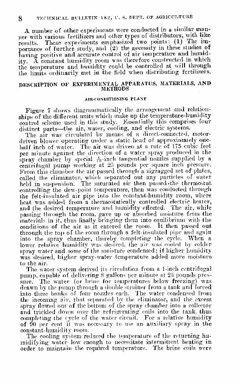
Fio-ure 7 shows dia<;rammatically the arrangement und relation- ships'^of the différent units which make up the temperature-humidity control scheme used in this study. Essentially tills comprises four distinct parts—the air, water, cooling, and electric systems.
The air was circulated by means of a direct-connected, motor- driven blower operating under a static head of approximately one- half inch of water. The air was driven at a rate of 1T5 cubic feet per minute against the direction of a water spray produced in the spray chamber by special iV-in^h tangential nozzles supplied by a centrifugal pump working at 25 pounds per square inch pressure. From this chamber tlie air passed through a zigzagged set of plates, called the eliminator, which separated out any particles of water held in suspension. The satuiated air then passed «the thermostat controlling the dew-point temperature, then was conducted through the felt-insulated air pipe into the constant-humidity room, where heat was added from a thermostatically controlled electric heater, and the desired temperature and humidity effected. The air, while passing through the room, gave up or absorbed moisture from the materials in it, thus finally bringing tliem Into equilibrium with the conditions of the air as it entered the room. It then passed out through the top of the room through a felt-lnsuhited pipe and again into the spray chamber, thereby completing the cycle. Wlien a lower relative humidity was desired, tlie air was cooled by colder spray water and some of the moisture condensed; if lilgher humidity was desired, higher spray-water temperature added more moisture to the air.
The water system derived its circulation from a 1-lnch centrifugal pump, capable of delivering 8 gallons jier minute at 25 pounds pres- sure. The water (or brine for temperatures below freezing) was drawn by tlie iiump tlirough a double strainer fiom a tank and forced into three banks of four nozzles each. The water condensed from the incoming air, that separated by the eliminator, and the excess spray flowed out of tlic bottom of the spray chamber Into a collector and trickled down over the refrigerating colls into the tank, thus completing the cycle of the water circuit. For a relative humidity of 90 per cent it was necessary to use an auxiliary spray in the constant-humidity room.
The cooling system reduced the temperature of the returning hu- midifying water low enough to necessitate intermittent heating in order to maintain the required temperature. The brine coils were

MECHANICAL APPLICATION OF FERTILIZEBS 9

10 TECHNICAL BULLETIN 18 2, TJ. S. DEPT. OF AGEICULTUEE
* a
supplied from a cold-storage plant with brine at a temperature of about 20° F., the flow of which was controlled by a needle valve. A number of additional valves and by-passes were used
to control accurately the rate of cooling.
The electric system was iiiiide up of two electric circuits, each ther- mostatically controlled. One cir- cuit maintained a constant tem- perature by means of the nichrome heating coils in the constant-lm- midity room. The other controlled the tempei-ature of the humidify- ing water by means of an electric hairpin immersion heater, thereby maintaining the right dew ])oint for the room conditions re((nired. In both circuits the expanding or conti'acting mcrciu'y column in the thermostat closed or opened the primary relay circuit, which in turn actuated a second relay and opened (if too hot) and closed (if too cold) the main lieating circuit. A wide range of heat control (200' to 2,000 watts) was available in the room according to the position of various knife switches. Two heat- ing units were placed in tlie water tank—one, of 1,000 watts, con- trolled manually by a snap switch; the other, of the same capacity, controlled automatically.
The constant-luunidity room it- self waH lined inside with insulat- ing board, well shellacked, and the sj)aces between this lining and tlie- outside walls were filled with saw- dust. The only entrance to the room was tlirough three tiglit-fit- ting doors in the vestibule.
Thi'ee hygi'othermographs were kept in this room. One was placed upon the floor, another upon a table, and the third upon a shelf near the ceiling. The maxinnun dilferenees between the records on these charts was not more than 2
per cent of relati\e humidity when the entire outfit was functioning properly. Figure 8 is a reproduction of a representative chart from one of these instruments. The hygrothermographs were checked almost every working day with a sling psychrometer, and reset whenever necessarv.
MECHANICAL APPLICATION OF FERTILIZERS 11
FERTILIZERS AND DISTRIBUTORS SELECTED
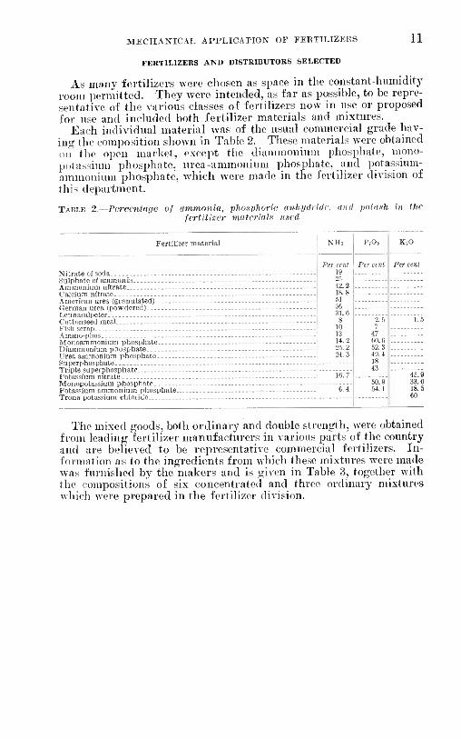
As many fertilizers were chosen as space in the constant-humidity room jjermitted. They were intended, as far as possible, to be repre- sentative of the various classes of fertilizers now in use or proposed for use and included both fertilizer materials and mixtures.
Each individual material was of the usual commercial grade hav- ing the composition shown in Table 2. These materials were obtained on the oi)en market, except tlie (liammoiiiuin phosjjliate, mono- potassiuni phosphate, urea-ammonium phosphate, and j)otassium- ammonium phosphate, which were made in the fertilizer division of this department.
TABLE 2.—Pcrccntaffe of ammonia, pliosphoric anhuilridc. fertiliser materialx ttsrd
and potiiKh in the
Fertilizer material
Nitrate of soda .-. Suli)hate of ammonia Ammonium nitrate Calcium nitrate - - - American urea (granulated) German urea (powdered) Leunasali)eter - Cottonseed meal Fish scrap Ammo-phos Monoammonium phosiihate Diammonium phosphate Urea ammonium phosphate Superphosphate Triple superphosphate — Potassium nitrate Monopotassium phosphate Potassium ammonium i)liosphate-. Trona potassium chloride
Per cent 19 25 42.2 18.8 61 66 31.6
8 10 13 14.2 25.2 24.3
PiOj
2.5 7
47 60.6 52.3 49.4 18 43
50.9 54.1
46.9 33.6 18.5
The mixed goods, both ordinary and double strength, were obtained from leading fertilizer manufacturers in various parts of the country and are believed to be representative commercial fertilizers. In- formation as to the ingredients from which these mixtures were made was furnished by the makers and is given in Table 3, together with the compositions of six concentrated and three ordinary mixtures which were prepared in the fertilizer division.

12 TECHNICAL BULLETIN Í82, U. S. DEPT. OF AGRICULTURE
I
(9 ON)
(î 'ON) '] ^
CI-6Ï-CI 5 <» -ON) ! i5
EI-CE-EI ■
te -ON)
(I -ON) !
H-9I-0I g
05-51-8
0I-9I-t
K-(B-0
S-9-5I
0I-9-OI j
9-0I-I' i
II O
S-ST-Î
e-6-E (E -OK)
E-6-e te 'ON)
E-6-E (I 'ON)
9-0-6
t-8-»
ss
?s
6-8-E
O'S
'OM
ss
at >o
-otcr-coco"^'^''"'^^ = t- CO M «g
I o" « <-" M ■«■ e-i us ■ect-OrH(DoootO"V.-<rt->f"
3 o aa
2«^
■V3 c h c-
Z OT«;uoü £-■
00000'""4;ioO.OOOOOOË

MECHANICAL APPLICATION OF FEIiTILIZERS 13
- "
1 1
¡ i
-
1
- § 2
i 3 '^
1 5
IM - - - - - 1
g gg
8 1-1 • i i
g g i
§ §
:g^3gE?SSB
-
d
1 c c
e
0.
c
1 1 c
E S c
c e
1
1 c c C
£ E-
« 1
a
1
'

14 TECHNICAL BULLETIN 18 2, U. S. DEPT. OF AGRICULTURE
By concentrated fertilizer is meant a material or mixture contain- ing a total of plant food, calculated as ammonia, phosphoric acid (PoOs), and potash, equal to or greater than 30 per cent of its weight. In addition to several concentrated mixtures obtained on the market, a ininiber of mixtures were made up containing four or five times the amount of plant food present in the usual grade of connnercial fertilizer. Several of them also contained 10 per cent of organic animoniate. They are the most highly concentrated fer- tilizers it is possible to make commercially at present and contain about C5 to 70 per cent plant food.
High-analysis and concentrated mixtures, which were first intro- duced only à few years ago, are rapidly coming into general use. Some of those used'in tliis study contain double the amount of plant food of several of the most popular grades of ordinary mixtures. Two of them, the 4-lG-lO and 8-10-8, correspond to two of the ordi- nary mixtures included in this list.
Mechanical analyses were made of the fertilizers used in these experiments. The results are given in Table 4. The analyses were made by shaking about 1 kilogram of each fertilizer in a series of standard screens, ranging from 3 to 200 meshes to the linear inch, until no more passed through them. The 3-5 mesh fraction, for example, was composed of particles passing through a 3-mesh and held on a 5-mesh screen. The fractions separated in this way were weighed separately and the percentages calculated.
TAIII.E 4.—Mevhiinical analyses of expeiHmcntal materials
Ordinary fertilizer materials: Superphosphate Sulphate of ammonia. Nitrate of soda.. .- Nitrate of lime Fish scrap. Cottonseed meal - Peat - - -
Concentrated materials: Urea - Urea ammonium phosphate Ammonium nitrate Leunasalpeter Ammo-phos .- Monoammonium pliosf)hate- Diammonium i)hosphate Triple superphosphate Potassium ammonium phosphate.. Monopotassium ¡ihosphate Potassium nitrate - Trona potassium chloride
Ordinary mixtures, commercial; 2-8-5 - 3-0-3 4-8-4... »-0-« .-
Ordinary mixtures, si>ecial: (No. 1) 3-»-3 (No. 2) 3-9-3 (No. 3) 3-9-3
High-analysis mixtures, commercial: 4-10-6-- 10-8-10.- 12-6-2
Material separated into screen sizes of—
3-S mesh
2.38 1.80
1.27 .31
1.10 .26 .36
5-10 mesh
10.85 .31 .37
1.32
18. 25 26.35
10-20 mesh
81.82 17.39
7.64 1.26
42.28 40.38 18.45 2.5. 61
8.73 35.32
2.89 8.61
17.83 12.46 20.61 11.57
4.95 15.93 1.05 5.61 3.50 I 19.03
20-40 mesh
Per cent 24.22 39.63 89.50 35. 43 31.64 25.83 30.46
93.41 89.88 85.15 21.43 10. 77 98.41 34.68 2.40 9.78
84.34 85. 71 12.00
25.48 24.92 29.60 30.85
26.49 28.85 26.37
22.53 25.20 23.54
40-80 mesh
80-200 mesh
Per cent: Per cent 14. SI I 12.34 54.44 8.84 : 9.14 !
15.14 ' 27.06 19.43
3.88 8.98
14.22 1 30.16 8.98 : 1.06
42 77 2.39 ,5.43 I
11.02 ' 12,57 63.60 I
6.93 1.66 1.71
12.40 27.91 17.54
2.71 1.14 .63
18.97 10.63
.,53 16.62 2.81 5.14 4.04 1.72
24.26
20.38 18.56 38.01 21.02 IS. ,58 14. M 33.61 20.28
27.15 43.31 27.40 41.10 39.66 32 04
20.43 23.23 28.87 36.66 29.76 21.3S
Finer than 200
mesh
Per cent 48.83
.23
.38 6.42
.08
.15
TÓ3 .08
1.38
.24
8.83 2.03 6.31 2.8«
3. OS 2. es 2.03
11.83 3.4S 2.46

MKCH.VNIC.VL APPLICATION OF FERTILIZEKS 15
TABLE 4.—Mechanical analyses of experimental materials—Continued
Material separated into screen sizes of—
Fertilizer 3-5
mesh
Per cent .24 .40 .86 .24 .56
6-10 mesli
10-20 mesh
20-40 mesh
40-80 mesh
80-200 mesh
Finer than 200
mesh
Concentiated mixtures, commercial: Per cent 3.08 6.07
17.24 6.23 1.66 4.13
Per cent 19.67 16.19 26.00 24.72 16. 38 19.01
2.29 6.45 8.60 3.03 2.10 6.67
Per cent 36.78 21.00 26.72 22.72 31.87 36.36
33.59 36.36 43.89 31.61 22.10 37.78
Per cent 32.23 24.29 15.62 18.68 25.27 24.79
29.77 25.45 22.62 31.62 42. 11 25.55
Per cent 8.89
23.82 14.66 27.41 26.28 16.11
31.26 20.10 21.31 30.15 31.35 27.52
Per cent .11
8.57
l()_l(i_14 .60 Concentrated mixtures, special:
3.09 12.64
(No. 3) 13-39-13 .45 .61
2. U
3.12 3.18 .23
2.48
Ten distributors, representing types commonly used, were chosen for this study and are illustrated in Plates 1 to 5A, inclusive. Gen- eral spccifícations are given in Table 5. More detailed descriptions of these distributors will be given under " Distributors, their con- struction and operation" (p. 42).
TABLE 5.—Specifications of fertilizer distributors used
Dis-
utor ^ '^^''**' "' distributor No. 1
1
Type of feed Agita- tor in
hopper Delivery-rate control
Manufacturers' delivery rating
Mini- mum
Maxi- mum
Yes...
Yes... No....
Yes.., Yes...
No
Gate and feed-wheel speed.
Depth of plow and plate .speed.
Pounds per acre
30
24 300
250 200
Poundi per acre
1,135 1 ment.
do 1,250 3 Potato-planter attach-
ment. 4. : do
Revolving plate and plow.
3,000
3,500 Revolving plate and
deflector. Revolving plate and
plow. Endless conveyor Revolving cylinder,
top delivery.
Gate and feed-plate speed,
do
3,400
G ' Corn-planter attach- ment.
7 Broadcast or 3-row No..-- No.---
No
Yes...
Gate Cylinder speed
Gate and amplitude of knock.
Conveyor speed
120
200
480
2,50
10 ' do (Oscillating plate.) Screw conveyor - 900
EXPERIMENTAL METHODS
About 40 or 50 pounds of each of the fertilizers described was spread in a wooden tray measuring 18 by 30 by 2.5 inches. These trays had burlap bottoms supported by three small wooden strips.
The trays were supported on racks in the constant-humidity room so as to obtain the best possible ventilation of the fertilizers. There was a clearance of 2 inches between the drawers, and each tier was entirelv clear of the wall on all sides. A 14-inch fan on the opposite

16 TECHNICAL BULLETIN 182, U. S. DEPT. OF AGRICULTURE
side of the room kept the air circulating all around them except when dust was being raised in the room, when a tight curtain was drawn about them. One tier of drawers is shown ni Plate 5, B. Each tray with its contents was weighed daily on a platform scale sensitive to 0.01 pound, as long as any change in weight was recorded. After weighing, the fertilizer was dumped into a metal tray, well stirred, and returned to its original drawer. The metal tray was carefully brushed to insure the return of all of the material. After a given substance had weighed the same on three consecutive days, it was considered to be at equilibrium with the atmospheric condi- tions. To make sure that this was the case, the daily weighing was continued after the fertilizer had been used experimentally until all of the experiments at that humidity and temperature were com- pleted when, if any material had shown a further change in weight, the experiments with that material were repeated.
Distributor No. 1 was chosen for most of the experiments through- out this work because it is representative of one of the principal types of distributor now used in this country. It has a wide range of delivery rates and is capable of convenient and positive adjustment. In studying the drilling properties of fertilizers it was necessary to use the same distributor for each set of experiments in order that the results secured might be com])arable.
In most of the exi^eriments the gates were set at notch 10 on the gate-lever scale, which gave one-tliird of the maximum opening and which, according to the manufacturer's table should give 80 jjounds per acre with the slow-s])ee(l gear. Tliis rate is lower than is com- monly employed at present but ai)proximates the rate that ]H-<)bably would be used with concentrated fertilizers. With fast-speed gears tliis setting, according to the same table, gives 375 pounds per acre which is within the range of rates frequently used with commercial fertilizers. In practically all of the experiments both speeds were used. For reasons whicli will be explained later, only the slow- speed delivery rates are given in the tables.
A revolution counter automatically registered tlie turns of the main axle. By means of the clutch'the machine could be .started and stopped almo.st exactly at the instant the counter rogisterecl a revolution. Weights of fertilizer delivered when the machine was run the nunibei- of revolutions corresi)onding to an advance in the tield of 100, 500, 1.000, and 4,000 feet were all exact multiiiles of the lowest weight to within 0.01 pound. It is believed, therefore, that no error was introduced in starting and stopping the drill.
In making a test, sufficient material was placed in tlie drill to give a head of about 8 inches. The machine was run for a few minutes to insure that the fertilizer was flowing normally from all units, when the clutch was thrown out, and the material'delivered was re- turned to the hopper. The machine was started again, and when the revolution counter registei-ed a nund)er corresponding to 250 feet advance for fast s|)eed. or 1.000 feet for slow speed, the fertilizer caught in a pan beneath the delivery tubes was accurately weighed and returned to tlie liopper. The shorter time for fast speed was used so that the dejilh of fertilizer in the liopper should not be re- duced to a point where this would materiallv affect the results. Not le.'^s than tliree closely agreeing determinations were made in any ca.se.
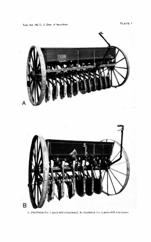
Tech. Bul. 182. U. s. Dept. of Agriculture PLATE 1
A, Distributor No. 1, grain-drill attachment; B, distributor No, 2, grain-drill attachment
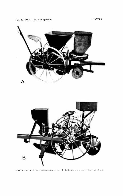
Tech. Bul. 182. U. S. Dcpt. of Agriculture PLATE 2
Si - ■ .)l^^^
A, Di.^ilributor X". :i, [.otalc-l'liniH'r ii"'"l""<""l : "■ 'li.-ilriliiitcT \ci. 1. iioliitn-phiiitfr ;il(!icliiii('rit

Tech. Bul. 182, U. S. Dept. of Agriculture PLATE 3
A, Distributor No. 5, potato-planter attacliment; B, distributor No. 0. corn-planter attachment

Tech. Bul. 182. 11. S. Dept. of Agricultui

Tech. Bul. 182, U. S. Dept. of Agricuitu:
A, Distributor Xo. 10. H. Interior of constant humidity room, c, weighing pan; d, fertilizer dis- irilnitor; (. fertilizer drawer;/, hygrothermograph; g, revolution counter; h, dust screen
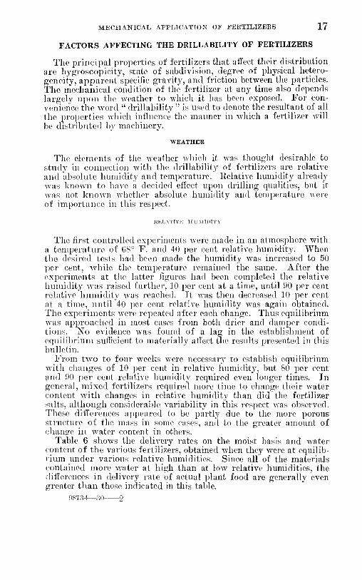
MECHANICAL APPLICATION OF FEETILIZEES 17
FACTORS AFFECTING THE DRILLABILITY OF FERTILIZERS
The principal properties of fertilizers that affect their distribution arc hygroscopicity, state of subdivision, degree of physical hetero- geneity, apparent specific gravity, and friction between the particles. The mechanical condition of the fertilizer at any time also depends largely ujion the weather to which it has been exposed. For con- venience the word " drillability " is used to denote the resultant of all the properties which influence the manner in which a fertilizer will be distributed by machinery.
WEATHER
The elements of the weather which it was thought desirable to study in connection with the drillability of fertilizers are relative and absolute humidity and temperature. Relative humidity already was known to have a decided efl'ect upon drilling qualities, but it was not known whether absolute humidity and temperature were of importance in this i-esjoect.
HKLATIVE HUMIDITY
The first controlled experiments were made in an atmosphere with a temperature of 68° F. and 40 per cent relative humidity. When the desired tests had been made the humidity was increased to 50 per cent, while the temperature remained the same. After the experiments at the latter figures had been completed the relative humidity was raised furthei-, 10 per cent at a time, until 90 per cent relative humidity was reached. It was then decreased 10 per cent at a time, until 40 per cent relative humidity was again obtained. The experiments were repeated after each change. Thus equilibrium was apjjroached in most cases from both drier and damper condi- tions. No evidence was found of a lag in the establishment of equilibrium sufFicicnt to materially affect the results presented in this bulletin.
From two to four weeks were necessary to establish equilibi'ium with changes of 10 per cent in relative Innuidity, but 80 per cent and 90 per cent relative humidity required even k)nger times. In general, mixed fertilizers required more time to change their water content with changes in relative humidity than did the fertilizer salts, although considerable variability in this respect was observed. These differences appeared to be partly duo to the more porous structure of the mass in some cases, and to the greater amount of change in water content in others.
Table 6 shows the delivery rates on the moist basis and water content of the various fertilizers, obtained when they were at equilib- rium under various relative humidities. Since all of the materials contained more water at high than at low relative humidities, the differences in delivery rate of actual plant food are generally even greater than those indicated in this table.
98734—30 2

18 TECHNICAL BULLETIN 18 2, V. S. DEPT. OF AGRICULTUKE
TAULE 6.—Effect of changes in relative humidity at 68' F. upon the water con- tent of fertilizers and. their delivery rate by distributw No. 1
[Calculations are on the moist basis]
Water content (per cent) and delivery rate (pounds per acre) of fertilizer distributed at percentage relative humidity of—
60 50
Ordinary fertilizer materials: Superphosphate Sulphate of ammonia Nitrate of soda - Nitrate of lime Fish scrap Cottonseed meal Peat
Concentrated fertilizer materials: Urea, granulated. Urea ammonium phosphate. Anunonium nitrate - Leunasalpeter Amnio-phos Monoammonium phosphate Diammonium phosphate Triple superphos[)hate Potassium ammonium phos-
phate Monopotassium phosphate- . Potassium nitrate Trona potassium chloride...
Ordinary mixtures, commercial: 2-8-5 3-9-3 4-8-4 : 9-0-0
nigh analysis mixtures, _ com- mercial:
4-10-f. 10-8-10 12-(J-2
Concentrated mixtures, com- mercial:
0-20-20 4-16-10 4-24-4 8-12-20--- 8-16-8 10-16-14
Special: (No. 1) 14-42-14 (No. 2) 14-43-14 (No. 3) 13-39-13 (No. 4) 13-39-13 (No. 5) 13-41-13 (No. 6) 17-20-17 ,
Pet cent 0.44 .03 .23
14.79 £.60 6.82
11.69
.07
.11
.02
.09
.76
.29
.24 2.44
.23
.14
.27 -.14
2.54 3.42 2.33 3.75
1.30 2.44 1.80
.85 2. 14 1.42 1.79 2.02 1.72
.05
.32
.58
.3
.08
.00
.\verage of 14 remaining drillable at 90 per cent relative humidity 1. 57
Lbs. i ver j ncTe
102.9,5 82.76I
135.041 100.48, 58.95 48.35 91.04;
73.33Í 78.41^ 9P.4r 88.28 80.59 104.98 06. 79'
11.5.87
06.05: 117.18, 123.71 104.11
87. 85 78.26 93.36 84.07
94.09 94. 6' 88.28
118.34 92. 64 81.75 98.30 105.56 93.94
99. 75 53. 58
104.98 109.06 104.54 95.69
Per cent 0.87
.12
.40 24.77 0.68 7.47
12.90
Lbs. per
70
! Lbs. Per ' per Per
acre cent acre ' cent 100.77: 1.06 93.65: 1.06 82.471 .23: 69.12i .53
125.451 .51112.09' 24.39| 1 (') ¡ 58.081 7. ,54¡ 60.34: 47.04 8.93: 4,5.3042.24 90.31 14. 12: 89.88:15.
.14 70.57
.35 70.42
.17¡ 89 18!
.19; 82.021
.95! 81.02
.3i;l04.9S
.74; 03.00 3.24113.98
.30' 06.21
.24 112.68
.28118.05
.16 92.20
2.80 85.96 4.89 74.05 3.39 91.04 5.86 07.06
2.00 83.34 2.97 97.14 0.98 00.84
1.35 2.80 3.31 2.62 2.96 2.06
.12 1.35 .83 .51 . 14
1.12
107.30 90.46 70.42 96.50
101.93 92.93
.31! 63.
.53¡ 66.
.38: 73.
.31 76. 1.21 84. .42 101.
1.23: 69. 4.45I1II.
1 .43' 67. .47 105. .2911.5. .20 77.
3.90 78. 7.67; 73. 4.64' 81. 8.66 61.
45 .76 50! 4.39 33! 08: 4.03 07; 1.6,3 ^ . 51 63 1.61 61 0.86
.65
.82
.44 1.38
Per cent 3.10 2.00
Lbs. per acre 85.67 51.55 (') (')
64.89 43.85 13.35 90.16 16.82
56.90-. 6.8I!.. (^) - 900!--
84.651 8.36 96.12: ..61 ,55.611 4.99
107.16: 9.83
I 10.91 15.43 15.13 15.04
7.25 4,
14.72
2.76 82.18 3.57 94.38 8.12! 66.32
1 1.04j 90.85, 6.09 3.90 80.83 9. 5.27, 75.7911.65 3.371 93.941 6.46 3. 81! 90. eo! 6.23 2.77; 89.59: 8^24
90.66 .31 40.40, 3.83 98 74! 1.20
107.88! .79 101.35 .26 88.43 1.79
82.33! 4. 33.84! g 5Q 91.O2I 4.19 96.99J 4.24 90.31, 1.04 78.99 6.22
67.23 1.03 94.821 1.25 96.70' .61 53.72 4.96
i9.97'29.96 f3.45i24.83 ,56.19 28.28 5.52'--
67.52 84.65 10.45
86.64 69.12 69.41 89.44 80.44 56.34
9.87 14.37 67.06 62.58 65.34 17.71
21.69 22.76 11.87 11.
92.58; 4.49; 80.36
16.09 19.16
7.61 7.01 3.31
Lbs. per acre 79.5 11.76 (') (')
£3.14 62.27 89.46
(') « (') « 66.63 90, 6.82
106.68
63.31 86.38 80.83 28.17
1.89 15. 26 9 15 (')
58.23 22.94 m
Per cent 14.82
16.27 4.17
0.02 3.27 1.36
(2) 36.43: 6O.84i4i.i9 53.721 60.2619.01 (') « (=)
33.6921.12 12.78,16.32 22.9410. 65 (')
Lbs. per acre 57.36 (') (') (') (=) «
87.99
(') (') (') (') 34.27 71.00 m
90.60
71.44 39.64 80.44
(.') (') (') (') (■)
3.78
m 8.42 (')
55.76 (') (.') O 3.92 4.21 4. ,50 O
1 In solution. ■ î Undrillable due to absorption of moisture. 3 Decomposed.
The moisture contents recorded in the accompanying tables were determined by placing 10 cubic centimeters of the materials in a weighing bottle and drying in a vacuum desiccator well supplied with dry phosphorus pentoxide. After a reasonable length of time had elapsed the samples were weighed daily until no further loss of weight was recorded. This required a month or more but gave better results than the official method.
Nitrate of lime, or Norwegian saltj^eter, was perfectly dry and drilled exceptionally well in an atmosphere of 40 per cent relative

MECHANICAL APPLICATION OF FEETILIZEES 19
liuiiiidity. At 50 per cent relative humidity it was soggy with moisture and drilled very poorly, and at 60 per cent relative humid- ity it had entirely liquefied.
Chilean saltpeter, or sodium nitrate, drilled excellently at 40, 50, and 60 i)er cent relative humidity, but could not be handled at all in this distributor wlien tlie liumidity was 70 per cent or higher.
8ul])hiite of ammonia drilled very well at 70 per cent relative humidity, but was entirely unsatisfactory at humidities above this.
Su])erphüspliate was too dusty at 40 per cent relative humidity ami too damp at 90 per cent for best results, but could be distributed ¡done at any humidity tried; it did best at 70 or 80 per cent. At !iO per cent the delivery rate was only about one-half of tliat at 40 per rent.
Of tlie new concentrated nitrogenous fertilizers, urea, ammonium nitrate, and leuiiasalpeter gave results very much like those for sodium nitrate, although urea could be drilled at humidities 10 per cent higher than could nitrate of soda.
The concentrated phosphates, ammo-phos, monoammonium phos- phate, triple superphosphate, and monopotassiiun phosphate, could be drilled excellentlj' at all humidities, although at reduced rates at the highest humidity.
Diammonium phosphate was fully as satisfactory as sulphate of auunonia but not nearly so satisfactory as monoammonium phos- phate. It gave off ammonia and became a i)asty mass at 90 per cent relative humidity.
Peat was unpleasantly dusty in an atmosphere of 40 per cent relative lumiidity, and fish scrap and cottonseed meal decayed in one of 90 per cent. These materials differed from the water-soluble ones. howcA'er, in one important respect. They distributed at practically the same rate per acre at every degree of relative humidity.
Potassium ammonium phosphate, although containing more water at 90 per cent than at lower relative humidities, coidd be drilled at almost the same rate throughout the range, thus behaving like an organic ammoniate in this respect. The uniformity of the rate be- comes more apparent when allowance is made for the moisture con- tent, as is seen in Table 7.
ÏAI1LE 7.—Dclircrj/ rate of potassium amnwiiiiim pliospliate for various relative liumiditic.1 on the dry and moifst bases
Basis
Pounds per acre delivered at percentage relative humidity of—
40 50 60 70 80 90
05.05 64.90
00.21 86.01
07.00 07.37
07.23 60.79
63.31 02.06
71.44 Dry -- 67.14
Of the 19 mixtures used in these te.sts, only one could be drilled satisfactorily when at equilibrium with an atmosphere of 90 per cent relative humidity, and this one, the 8-16-8, at only one-half the rate at which it distributed in an atmosphere of 40 per cent relative humidity. The variations in delivery rate were of the same order for the mixtures as for the individual ingredients.

20 TECHNICAL BULLETIN 18 2, U. s. DEPT. OF AGRICULTURE
As a class, the double-strength mixtures were less affected by hi^h relative humidity than were similar mixtures of ordinary grade. The concentrated mixtures as a class were very similar in their drilling properties to the ordinary grade commercial mixtures.
Some experiments were also made at relative humidities of 20 and 30 per cent ; these in general gave the same delivery rates as those at 40 per cent relative luimidity. .
At relative humidities lower than 50 per cent all tertilizers tested—whether salts or organic ammoniates, materials or mixtures, low grade or concentrated—without exception, were dry and in good condition and could be drilled satisfactorily in distributors that were suitable in other respects. At 50 per cent relative humidity all of the samples distributed well excepting calcium nitrate or nitrate of lime.
The average rate at which over 50 different fertilizers were dis- tributed in an atmosphere of ßO per cent relative humidity was 81.21 pounds per acre (manufacturer's rating, 80 pounds per acre).
At liumidities of GO per cent or above, certain fertilizers could not be drilled at all, and the higher the relative luimidity the fewer were the substances that could be distributed. The delivery rates of different materials at liumidities of GO per cent or above varieil from nothing to well over 100 pounds per acre.
The delivery rate for any given fertilizer varied invei-sely witli the relative luunidity, and the nature and amount of this variation depended upon the hygroscopicity of tlie fertilizer, which factor will be considered later.
The relative humidity of unconditioned air fluctuates constantly, being highest at night and lowest in mid afternoon. During the night, in the Atlantic Coast States, it often attains 100 per cent and by 2 p. m. of the same day may fall to 30 per cent. A fertilizer in storage is i)rotected somewhat from this rapid change by its own bulk, by tlie bags containing it, and sometimes also by reason of its being in a heated building where the humidity does not undergo marked change. In an unheated building the relative humidity will change just as it does outside with equal changes in atmospheric temperature. At night the air in the spaces between the fertilizer particles cools and decreases in volume, whereupon some outside air is drawn into the mass. When the mass becomes heated again some of the air is expelled. Thus the changing atmospheric conditions permit the fertilizer to absorb moisture at times and to dry out at other times. It never reaches a state of equilibrium, but tends to contain the amount of moisture corresponding to the mean relative humidity to which it is exposed.
ABSOLUTE HUMIDITY
Some of the results obtained in studying relative humidity and temperature were tabulated in such a way (Table 8) as to show the relation, if any, of absolute humidity to the water contents and delivery rates of the fertilizers. No correlation, however, is ap- parent. At both high and low absolute humidities good and poor

MECHANICAL APPLICATION OF FEETILIZEES 21
i-esults were obtained, depending upon the combination of relative liumidity and temperature. The differences shown in the table are due to variations in relative humidity and temperature, as indicated in Tables 6 and 9, respectively, and it is believed that absolute humidity has no definite relation to the physical properties of fertilizers.
TABU: 8.—Relation of absolute humidity to the water content of three fertilizers and to their rate of delivery by distributor No. 1
j '" \ 3-9-3 commercial Monoamraonium Rela- Tem-
öoaiuni Diiraie fertilizer phosphate Absolute tive humidity humid- pera-
ture ity Water Delivery Water Delivery Water Delivery content rate content rate content rate
1
Grains per Pounds Pounds Pounds cubic foot Per cent "F. Per cent per acre Per cent per acre Per cent per acre
2.04 60 60 0.20 12,5. 02 4.12 80.44 0.24 103.63 2.46 60 60 .32 126.90 5.60 76.08 .30 104.83 2.86 70 60 1.03 97.43 7.85 67.81 .38 100.91 3.00 40 68 .28 130. 10 3.42 78.26 .29 104. 98 3.26 80 60 (') 16.60 50.00 .62 96.06
1 3.74 SO 68 "'"."4Ö"" 125.46 7.57 74.05 .31 104.98 ! 3.94 30 86 .19 112.82 2.26 73.62 .25 89.88 ; 4.48 60 68 .91 93.36 8.85 73.33 .42 101.20
6.24 70 68 (>) 15.40 19.75 .51 90.12 6.26 40 86 "V2Ô" 126.61 4.91 72.31 .38 103.63 5.99 80 68 (') 24.83 8.13 .61 90.75 6.56 50 86 ""'."44" 107.16 7.37 66.79 .32 102. 22
¡ 7.90 60 86 (') 9.71 63.00 .50 98.74
1 Undrill able, ow ng to ab Sorption of moisture.
TEMPER.J iTUEE
Experiments intended to show the effect of temperature changes upon the drilling qualities of fertilizers were conducted in the same manner as those designed to test the effect of relative humidity. The humidity was held constant at 60 per cent, and experiments were run at temperatures of 50°, 68°, and 86° F., which it was believed represent the range encountered by farmers actually using fertilizers.
The effects of temperature changes upon the drilling qualities of fertilizers, over the range ordinarily encountered in applying them, are slight in comparison with those produced by changes in relative humidity, as will be observed by referring to Table 9. The greatest difference in delivery rate was obtained with ammonium nitrate. It varied from 31 pounds per acre at 86° F. to 83 pounds per acre at 50°, when the machine was set to deliver 80 pounds per acre. The rate of delivery of nitrate of soda and a few other nitrogenous salts showed considerable variation with changes in temperature, but most of the fertilizers were only slightly affected. The delivery rate of phosphates as a class varied less with temperature than did that of the commercial mixtures.

22 TECHNICAL liULI.ETlX IS 2, V. S. DEPT. OF AGlîICULTUliE
TABLE 9.—Eftect of air-temperature changes at 60 per cent relative humidity upon tlw, tcater content of fertilizers and upon their rate of deliverii hij distributor No. 1
50° '■
68° F. 86° F.
Fertilizer Delivery
rate Water
content Delivery
rate Water
content
Per cent
1.05 .23 .51
Delivery rate
Wat«- content
Ordinary fertilizer materials:
Pounds per acre
99.17 71.58
126.90 3.05
69.39 48.79 92. 78
70 86 75.65 83.34 90 60 84.22
104.83 63.89
118.48 69.41
111.61 119.21 88.28
80.83 77.54 93.07 78.84
86.97 94.96 86.96
115.14 93. 80 85.38
100.33 100.91 98.88
96.54 35.57
104.11 109.48 103.96 89.16
Per cent
0.96 .22 .32
24.95 7.36 8.87
12.70
.05
.11
.08
.13 1.19 .30 .39
4.34 .20 .24 .27 .15
3.51 5. 66 4.44 5.73
1.70 2.74 2.76
1.16 3.39 3.64 3.16 3.56 2..'i9
.19 1.56 1.11 .71 .21
1.43
Pounds per acre
93.65 09.12
112.09 (1)
. 56.34 45.30 89.88
63.45 66.60 73.33 76.08 84.07
101.20 69.53
111.61 67.66
105.27 115.43 77.64
81. 89 73.33 81.31 01.13
, 82.18 94.38 56.32
96.85 86.83 75.79 93.94 90.60 89.59
82.33 33.83 91.62 96.99 90.31 78.99
Pound ft per acre
87.41 6011 84.51 (') 66.34 45.74 85.52
58.23 34.99 30 93 64.03 81.02 98.74 60.11
108.46 65.34
103.53 98.88 76.96
78. 55 63.60 76.23 39.20
79.86 92.06 49.37
100.33 84.65 71.44 96.12 89.89 88.86
56.77 32.67 87.70 93.61 85.23 56.48
Per cent
1.20 .31
1.17
7.64 8.93
14.12
.31
.53
.38
.31 1.21 .42
1.23 4.45 .43 .47 .29 .20
3.90 8.86 4.64 8.60
2.76 3. ,57 8.12
1.64 3.9« 5. 27 3.37 3.81 2.77
.31 3.83 1.20 .79 .26
1.79
7. 55 8.8S
15.05 Concentrated fertilizer materials:
.46 1.01 1.83 .07
1.24 ..50 .84
4.06 Potassium ammonium pho.si)liatc .54
.,53
.4'.'
.26 Ordinary commercial mixtures;
4.00 3 9-3 9.71 4 8-4 5.12
9.48 High-analysis mixtures, commercial;
4 10-6 10-8-10 - 3.91
». 05 Concentrated commercial mixtures:
1.96 4.18 6.44
8-12-20 --- .3.63 3.82 3.12
Concentrated special mixtures: .64
6.18 1.21)
No. 4. 13-39-13 --.. No 5 13-^1-13 - -
.87
.39 No. 6. 17-26-17 . 3.11
Average (excepting nitrate of lime).. 89.60 2.35 81.22 3.03 73.00 3.11
: t:ndrillable.
Otlior exiiorinients made at 40, 50, and 70 ]M'r cent relative Inmiidi- ties indicated tliat the relatioiisliips sliown in Table 9 for CO per cent hold n;ood «Generally. They neem to justify the conclusion that, m f;eneral. the drillinji properties of fertilizers improve and the watei- content diminishes as the temperature is lowered, ]irovided the I'ela- tive humidity is con.stant.
HYGROSCOPICITY
In <;eneral, all substances contain a certain anioimt of moisture when in contact with the atmosphere for any len.sth of time. The amount depends upon the chaiaiter of the substance and the vapor pressure of the atmosphere. P^very material containin<); water e.xeits

MECHANICAL APPLICATION OF FERTILIZERS 23
a vapor pressure. If this pressure is <;reater than that ot the atmos- phere to which it is exposed, the material will dry out until the vapor pressure is equalized. If the vapor pressure of a substance is lower than that of the air, that substance will absorb moisture. Ihus, a fertilizer will tend to reach a state of equilibrium m this respect with the atmosphere in which it is kept. The vapor pressure of the air changes considerably with changes in relative humidity and to a muciriess extent with changes of temperature such as occur in ordi- nary atmospheres.
When the vapor proí^sure of the atinospliere is appreciably lower tlum that of a saturated solution of a given salt, the equilibrium water content of tliat salt will be small and it will appear to be dry. In an atinospliere with a vai^or pressure equaling or exceeding that coriespondin!,' to a saturated solution of the salt, the latter will absorb water and feiid to become a solution. If suflicient time elapses it will liquefv completely.
For convenience thé relative humidity corresponding to the vapor pressure of the air which is equal to the vapor pressure of a saturated solution of a given salt is called tlie hygroscopic ])oint of that salt. Tliis point is ditîeient for every fertilizer salt. It has been deter- mined carefullv for a number of pure salts, and Table I'O gives the values i)ublishéd by Ross, îtlohring, and Merz (18). Determinations of the liygr()scoi)icities of these and other materials and niixtiires over a considerable range of temperatures were recently published by Adams and Merz (i). The hygroscopic points of impure fertilizer- grade salts will differ slightly'from the values in the table.
TARLP; 10.—Ifiigroscopic ¡mints of lyirioun fertiliser salts
Ferlilizcr salts
Calcium nitrate- Ammonium nitrate Sodium nitrate Urea Ammonium cliloride.. .\mmonium sulphate.
Relative hu- midity at—
68° F. 80° F.
Per cent Per cent S4. 8 ! 4«. .1 (i3. 3 sa. 4 74. 5 i 7.'i. 7 80.7 7^.2 79. 2 ' 77. i 81.0 81.1
Fertilizer salts
Diammoniuin l)hosi)hate Potassium ftiloride Monoammonium phospliate.. Monopotassium phosphate... Potassium nitrate. Potassium sulphate
Relative hu- midity af—
Per cent 83.2 85.3 93.1 93.2 94.5 97.0
16° F.
Per cent 82.8 84.4 92.9 93.0 93.3 99.5
Tlie hygroscopicity of a mixture of salts usually is gi'eater than tliat of its most hygroscopic constituent, but it may be less. If an impurity is a soluble salt, it will increase the hygroscopicity of the material containing it. Insoluble impurities have no effect. Sub- stances forming chemical combinations may either increase or de- crease the hygroscopicity; for instance, a mi.xture of superphosphate and urea is more hygroscopic than is either of these materials alone.
A conipari.son of the hygroscopic points with the delivery rates and water contents given in Table C shows definitely that the effects of relative humidity upon fertilizers are largely due to their hygro- scopicity. Th(> water content in every case increases gradually with increase in relative liumidity until the liygroscopic point is reached.
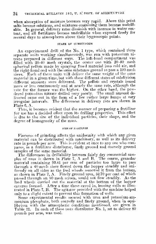
24 TECHNICAL BULLETIN 18 2, U. S." DEPT. OF AGEICULTUHE
when absorption of moisture becomes very rapid. Above this point salts become solutions, and mixtures containing them become undnll- able. In general, delivery rates diminish with increase in water con- tent, and all fertilizers become undrillable when exposed freely for several days to atmospheres above their hygroscopic points.
STATE OF SUBDIVISION
An experimental drill of the No. 1 type, which contained three separate units worldng simultaneously, was run with potassium ni- trate ijrepared in different ways. The left-hand compartment was filled with 20-40 mesh crystals, the center one with 20^0 mesh spherical pellets made by spraying fused material into cold air, and the right-hand end with the same substance ground to pass a 100-mcsh sieve. Each of these units will deliver the same weight of the same material in a given time, but with these diiïerent states of subdivision different amounts were delivered. The pellets and crystals issued more or less continuously and at nearly the same rate, although the rate for the former was" the higher. On the other hand, the pow- dered potassium nitrate drilled very poorly. Tlie small amount de- livered came out in the form of a few rather large lumps at very irregular intervals. The differences in delivery rate are shown in Plate 6, A.
Thus, it becomes evident that the manner of preparing a fertilizer for use has a decided effect upon its drilling properties. This effect is due to the size of the individual particles, their shape, and the degree of homogeneity of the mass.
SIZE OF PABTICI-ES
Fineness of grinding affects the uniformity with which any given material can be distributed with machinery, as well as its delivery rate in pounds per acre. This is evident at once to any one wlio com- pares, in a fertilizer distributor, finely ground and coarsely ground samples of the same material.
The differences in drillability between fairly dry commercial sam- ples of urea is .shown in Plate 7, A and B. The coarse, granular material containing 93.41 per cent of particles too large to pass through a 40-mesh sieve flowed down the hopper steadily and uni- formly on all sides as tlie feed wheels removed it from the bottom, as shown in Plate 7, A. Finely ground urea, 52.70 per cent of which passed through an 80-mesh screen, would not flow steadily. As the feed wheels carried out the material at the bottom of the hopper caverns formed. After a time these caved in, leaving wells as illus- trated in Plate 7, B. The agitator provided with the machine helped only to a slight extent to prevent this formation of wells.
Some experimental results secured with urea and potassium-am- monium phosphate, both coarsely and finely ground, when in equi- librium with the atmospheric conditions mentioned, are given in Table 11. In each of these tests distributor No. 1, set to deliver 80 pounds per acre, was used.
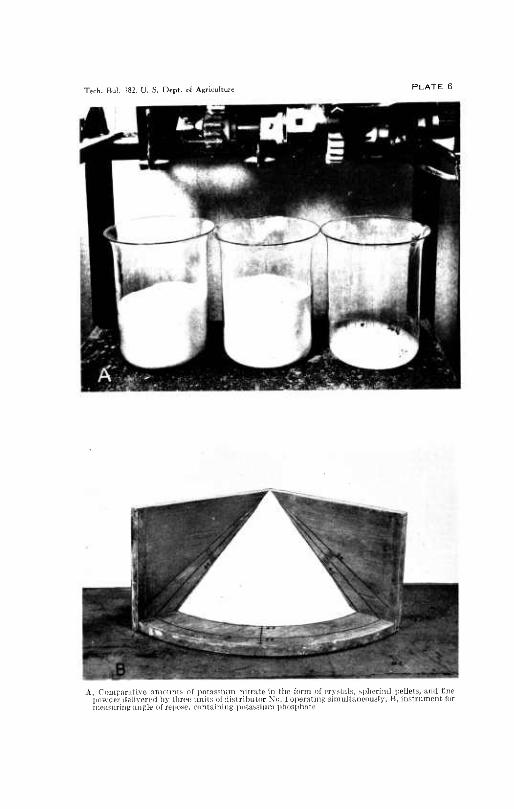
Tech. Bul. 182. U. S. Dept. of Agricultu
A, (.'oiiiparative ñtiumnls of ¡iotassiuin nitrate in the form of crystals, spherical pellets, and fine powder ilelivered by three unils of distributor No. 1 operating siniullaneously; B, instrument for measuring angle of reiK>se, containing potassium [thosphate
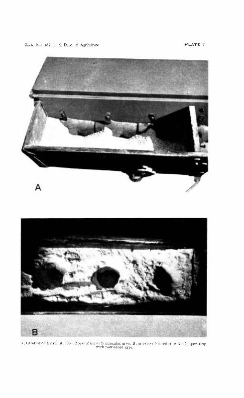
Tech. Bul. 182, L'. S. Dept. of Agriculture
A, IiiIcriordf-ii^lrihuturNo ■er iliiu w Uli trr iTiiil ir un' i H. int w iih pduilored urea
Tiorofilisiiibuldi \n 1 iiinniiint;

MECHANICAL APPLICATION OF FERTILIZEKS 25
TAIiLE 11. -Effect of subdivision on the drillabilitv of urea and potassiwn ammonium pliosiihate (it 08° I''.
Material
Material separated by screens with mesh ot—
State of subdivision 5 and 10 and
10 : 20
Urea - ' Powdereil
Per cent Per cent 1.35
Do. Do.
Potassium ammonium phosphate. Do
Granulated _ Sprayed l*owdered.__ Granulated-
1 59 "Í7.";i9' OO! 87
20 and 40 and 40 80
80 and 200
Per cent Per cent Per cent Per cent 20.27 26.67 I 27.34 25.36 93.41 3.88 2.71
100.00 -J 38.88 11.90 I 16.60 31.03 9.78 5.44 6.52
Material State of sub-
division
Urea ' Powdered._- Do Granulated . Do - Sprayed
Potassium ammonium I'owdercd.,- pho.sphatc.
Do..- Granulated.
Delivery rate, at perceni age relative humidity of-
Averagc devia- tion 1 in delivery
at percentage relative humid-
ity of—
Pounds per acre
54,3 73.3
179.8 66. 3
65.1
Pounds Pounds '¡Pounds 'Pounds per acre per acre per acre per acre
52. 6 70.6
176. 9 52.6
06. 2
30.5 03.5 I
171.0 I 43.3 ;
10.3 ■ 55.9 92.9 19.6
Pounds per acre
60
Per cent 61.09 19.36 17.85 69.39
11.37
1 Deviation is calculated on the basis ot 3-foot intervals of delivery.
The coarsely j>rouiid varietj- of both matei-ials diilled much more uniformly and the delivery rate was much less affected by chan^'es in relative humidity than"^ in the case of the powdered materials^. The granulated iiotassiuni-ammoniiim phosphate was distributed at neai-ly the same rate at all relative humidities from 40 to 1)0 per cent, while at high humidities the powdered material was delivered at less than one-half the rate prevailing at low humidities. The differ- ences between the two samples of urea were even more marked. In this connection it is interesting to compare the delivery rates for ordinary and trijile superphosphate at different humidities, as given in Table G. These inateiials were similar in physical properties, except that the ordinary su]3erphos|ihate was more ñnely ground. Here, too, there was less '\-ariation in the delivery rate and greater evenness of distribution with the coar.ser material. The ñner mate- rials in every case wei'e also much less satisfactory at low relative humidities because of excessive dustiness.
Of the materials used in these experiments, tliose which contained appreciable percentages finer than 200 mesh (.see Table 4), the super- phosphate particularly, were excessively dusty when the humidity was 40 per cent or lower. It was nece.-^sary, when working in the constant-humidity room with such materials at low humidities, to wear respirators, in spite of the fact that a curtain was drawn around the delivery tubes. Another curtain drawn around the fertilizer trays eil'ectively protected the other fertilizers from contamination. The 18 per cent superphosphate Avas still slightly dusty when at equilibrium in an atmosphere of 80 per cent relative humidity, but
26 TECHNICAL BULLETIN 182, U. S. DEPT. OF AGRICULTUHE
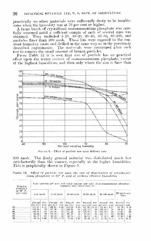
practically no other materials were sníficiently dusty to be trouble- some when the humidity was at 70 per cent or higher.
A large batch of crystallized nionoammonium phosphate was care- fully screened until a' sufficient sample of each of several sizes was obtained. They included 5-10, 10-20, 20-40, 40-80, 80-200, and particles finer than 200 mesh. These lots were exposed in the con- stant-humidity room and drilled in the same way as in the previously described experiments. The materials were rescreened after each test to remove the small amount of broken particles.
From Table 12 it is seen that size of particle has no practical effect upon the water content of luonoannnoiiium phosphate, except at the highest humidities, and then only where the size is finer than
50 60 70 80 Per cent relative humidity
FiGUHE 0.—Effect of particle size upon delivery rate
200 mesh. The finely ground material was distributed much less satisfactorily than the coarser, especially at the higher humidities. This is graphically shown in Figure 9.
TABLE 12.—Effect of parlicjp nizc upon the ivte of distribution of monoammo- nittm phosphate rtt 6S° F. and at various relative huniiditirs
Relative humidity at 68° F. (per cent)
40-.-. 60.... 60.... 70-... 80.... 90....
Rato (pounds per acre) and water content (per cent) of nionoammonium phosphate separated into screen sizes of—
Pounds per acre
103. 21 103.09 100.65 96.99 84.07 86.54
Per cent 0.27 .32 .41 ..■iO .87
3.07
Pounds per acre
106.85 107.16 106. 60 102.80 93.22 8«. 52
Per cent 0.29 .32 .43 ..64 .62
2.76
20-40 mesh
Pounds per acre
104. 98 104. 83 101.20 97.28 90 76 71.00
Per cent 0.29 .31 .42 .61 .61
2.97
40-80 mesh
Pounds per acre 107. 40 106. 72 102 86 97 43 84.61 29.18
Per cent 0 18 .20 .27 .35 .41
212
80 200 mesh
Pounds per acre
123. 49 120. 62 113.90 10,6. 71
7.6. 50 11.76
Per cent 0.17
.21
.26
.33
.48 2.51
200 mcsli and finer
Pounds per acre
SO, 70 78 99 76, 66 69, 9S 17,28 1,74
Per cent 0,28 ,34 .46 . .63
1.49 10.71
MECHANICAL APPLICATION OF FERTILIZERS 27
Humidity had the least effect upon the samples composed of the largest particles. It is believed that the trend shown by the residts for ainnioniuni phos])hate woidd be exhibited generally by soluble fertilizer salts, due allowance being made for differences in hvgroscopicity.
' In studying the effect of particle size on uniformity of distribu- tion the iK>rcentage deviations in delivery for successive 3-foüt por- tions were calculated. For this i)urpose the experimental drill was used in the constant-humidity room. It is realized that 3-foot inter- \als of deliverj' are rather long, but it was impossible to collect Y.-ith any degree of accuracy individual portions for a shorter dis- tance with the machine in the constant-humidity room. This subject was also studied under less j)erfect control of atmospheric condi- tions for l-foot intervals of delivery. The latter experiments will be described in a later section.
In making the uniformity tests the quantity of material issuing from one spout of the drill was collected in a succession of beakers whicli moved up at the rate of one beaker each second. Thirty such ¡)Ortions of each of several different fertilizers were collected and Aveioh<>d separately. Then the amount that each weight varied from the average weight of the 30 was found, and the percentage «leviation from the mean was calculated for the average of these weight deviations. If the distribution of the fertihzer were per- fect throughout the row so that each beaker received the same weight, this j)erccntage would be zero.
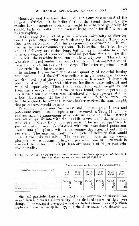
Pei-centage deviations for coarse and fine samples of urea and potassium-annnonium ])hosphate are jjresented in Table 11, and for various sizes of annuonium pliosphate in Table 13. The materials were all at e(]uilibrium with the humidities given, and the distributor was set to deliver 80 pounds i)er acre. The nearest a])i)roach to perfect distribution was obtained with the gi-anulated pota:s'um- ;-mmonium jjliosphate, with a percentage deviation of only 11.37 per cent. The machine itself has a cycle of delivery that would account for this variation. The best residts with the ammonium l>hosphate were obtained when the partitdes were 10 to 20 mesh in size and the material was kept in an atmosphei-c of 50 ])er cent rela- tive humidity.
TAIîLK K!.—Effect of particle size and relative huiniditij upon perecntaoc devia- tions in delivery of ammonium phosphate
liclativc humidity ii>cr cent)
Ammonium pliosphatc separated into strocn sizes of—
5-10 mesli
10-2Ü mesh
20-40 mesli
40-80 mesh
80-200 mesh
200 mesh
Ptr cent 31 36 31
Per cent 17 30
Per cent 24 32 31
Per cent 20 20 4H
Per cent 27 37
118
Per cent 30
70 46 90 - - 131
Size of particles had some effect upon evenness of distribution «'ven when the materials were dry, but a decided one when they were damp. The coarsest material was distributed almost as evenly when quite damp as when quite dry, but the finer sizes were distributed

28 TECHNICAL, BULLETIN 182, U. S. DEFT. OF AGRICULTURE
more and more irregularly as they became damper. In the case of the size finer than 200 mesh, in an atmosphere of 90 per cent rela- tive humidity 11 of the 30 beakers contained nothing, and the weights of the contents of the others ranged from 0.0005 to 1.2101 grams. This is explained by the fact that in a 200-mesh powder m the dry state some of the particles are usually so small and near each other that cohesion exists between them. When the particles are damp, however, the forces attracting them to each other will be very much greater, due to the surface tension of the liquid films.
The differences in distribution between the coarsest and finest mate- rials are much greater than one might suppose from a cursory exami- nation of the percentage deviations, because the larger particles were scattered throughout the row, while the smaller ones stuck together in little bunches, and in some cases the entire amount for 3 feet of row was delivered in one lump.
The efïe:t of size of grain on the rate of flow of several materials was investigated by recording the time required for 100 grams of material to flow through copper funnels having various-sized open- ings, and angles between the .sides eciual to 30°, C0°, and 90", respec- tively. Crystallized ammonium phosphate and potassium nitrate in the form of tiny spheres were very carefully screened and kept in the constant-humidity room until at equilibrium with 30 and 70 per cent relative humidities and a temperature of 68° F. A determination was made by setting the funnel with its axis vertical upon a tripod, placing a finger over the funnel opening, and then pouring the mate- rial into it. A stop watch was started at tlie same instant the finger was removed from the funnel opening. The numbers in Table 14, representing the time required for 100 grams to flow through by gravit^', are averages of four or five closely agreeing determinations. The 0()° funnel Avith a lO.OC-millimeter opening was used in the ex- periments recorded in the table. Other funnels with different open- ings gave results from which the same conclusions may be drawn.
TABLE 14.—Effect of particle sise on time required for 100 grams of crystallized ammonium phosphate and of sprayed potassium nitrate to flow from a 60" funnel mth a 10.06 millimeter opening
Crystallized ammonium pliospliate Sprayed potassium nitrate
Size of particle screen mesii of'part^ i cíes Apparent
specific gravity
30 per cent rela- tive hu- midity
70 per cent rela- tive hu- midity
Apparent specific gravity
30 per cent rela- tive hu- midity
70 per cent rela- tive hu- midity
Milli- 1 meters
5-10 j 2.83 10-20 ! 1.10 20-30 - .70 30^0 .40 40-('0 : 28 60-80 . 19 80-100 . If) 100-125- 13 12.')-157 10
0.83 .84 .84 .86 .86 .88 .90 .92 .93 .92 .88 .81 .70
Minnie (') 0 210 .lf8 .161 .136 .122 .119 .119 .132 . 153 .182 .220
{')
Minute (') 0.218 .178 .168 . 141 .134 .121 .121
141
1.19 1.22 1.23 1.23 1.24 1.24 1.23 1.23 1.22
Minute 0133
. 102
.080
.070
. 0,")0
.0I!3
. 05()
.068
.070
Minute 0.128 .099 .079 .088 .0P,5 .008 .073 .07.5
157-200 .08 200-250 .0")
.172 1.20 1 .079
. 21.Í 1. 18 i . 13,1) 250-.300 05
(0 300-3511 .044

MECHANICAL APPLICATION OF FEHTILIZEES 29
Each substance has a minimum size of particle that will flow bv •Gravity through an opening. This varies with the material and with ihe atmospheric conditions. For instance, 200 to 250 mesh ammon- ium phasphate in an atmosphere of 70 per cent relative humidity will flow freely, whereas 250 to 300 mesh size will not flow at all. Moreover, 125 to 157 mesh potassium nitrate in the same atmosphere will not flow. Of course, if the opening is large enough, chunks will break off and fall through, but the reference here is to a free movement of the individual particles upon one another. On the other liand, there is a maximum size of grain that will flow through an opening of given size. This size is approximately the same for all materials that will flow through that opening, but increases f;lightly the more nearly spherical the grains are. There is a mini- mum time required for particles of intermediate size to flow through any given opening.
If the opening and size of grains remain the same and the effect of molecular forces is imperceptible the rate of flow will vary with the friction of the material. The fertilizer with the lowest friction will flow most readily and in a proper distributor should give the best distribution.
In the piresent experiments coarse materials flowed at nearly the same rate when in equilibrium with both 30 and 70 per cent relative humidity; but finely divided ones required considerably more time, or did not flow at all, at a relative humidity of 70 per cent, although they appeared dry. The results given in Table 14 help to explain the differences in delivery rate shown in Table 12. They indicate that gravity flow is an important factor in delivery rate with this distributor.
Not only does the feeding mechanism of most distributors deliver a granular material in a steadier stream than a finely ground one but this difference is increased as the material passes down the de- livery pipe. Hard grains bounce back and forth from one side of the tube to the other, and when they collide the velocity of one particle is diminished while that of the other is accelerated. Thus the tendency is to spread the discharge still more uniformly in this case, and the material issues from the spout in the form of a spread- ing cone. A fine powder, on the other hand, shows a tendency to cohere in irregularly shaped masses, and this is greatly exaggerated if the material is damp. A familiar example is the difference be- tween clay and sand when slightly moist.
If fertilizers are distributed at the rate of 80 pounds per acre, each square foot of soil surface will receive 0.833 gram of material. The number of particles in this weight of potassium nitrate, in the form of tiny pellets of various screen-interval sizes is shown in Table 15.

30 TECHNICAL BULLETIN 182. V. S. DEPT. OF AGRICULTUIiK
TABLE 15.—Number of partUJes of various sizes per square foot rcheii tlie application is 80 pounds per acre
Average Particles
mesh diameter per square of particles foot
MiltimeUra Number 5-10 2.83 44
10-20 1.10 471 30-30 .70 3,301 30-40 .40 Ü, 332 4O-£0 .28 24, 450
Distributed uniformly over the surface of the soil, this quantity of fertilizer would make a layer only 0.007 niillimeter thick. The average diameter of the 20-30 mesh particles is about 0.700 milli- meter. The opening in a 325-niesh screen, about the finest obtain- able, is 0.044 millimeter. From these figures it becomes apparent that applying fertilizers uniformly at low rates is a very difficult matter. Fortunately, fertilizers do not need to be applied in a continuous layer over the entire area of a field but are usually placed only in the root zone of the crop where they dissolve and diffuse somewhat through the soil solution. However, they do not diffuse far.
In summing up the results of experiments on the size of particles, it was found that the least variation in delivery rate with changes in moisture content was with the 10-20 mesh size. The nearest ap- proach to uniform distribution was also obtained with the 10-20 mesh material, but the 20-40 mesh particles gave results almost as good. Particles larger than 10 mesh are too large for thorough incorpora- tion with the soil. Those smaller than 20 mesh are certainly satis- factory in this respect. Thus, the ideal size of grain for a fertilizer appears t« be about 20 mesh. Good results in distribution .should be obtained when the diameters of the particles of a fertilizer do not exceed 1 millimeter nor fall below 0.2 millimeter. No fertilizer is likely to give even fair results in distribution if it contains a con- siderable proportion of material finer than 200 mesh.
SHAl'K OK P.\liTUI.i:.s
Table 14 showed the rates of flow of various sizes of two materials with difl^erently shaped grains. One of these materials was in the form of oblong crystals and the other of little spheres. Both of these materials flowed quite freely, but for every size of each mate- rial it is observed that the same weight of spherical particles required only about one-half the time,to flow through the given opening that was required by the oblong particles. Part of this ditl'erence in rate of flow i.s due to difl'erence in specific gravity. Therefore samples of urea and of potassium nitrate were prepared in several ways. One sample of each consisted of unbroken crystals, another was ground so as to round off the corneis, and a third was made by spray- ing the molten material through a nozzle and catching it after it had congealed into pellets. The latter were rolled down glass plates to remove everything but spheres. The materials were carefully screened to 20-30 mesh sizes in each case, and 100 grams of each

MECH.\NICAL APPLICATIOIí OF FERTILIZERS 31
was caused to flow by gravity through a 10-mi!limetcr opening. The time required for this flow "was reeoi'ded with a stop watch. The results in Table 16 indicate that under the same stress such crystals will flow only about one-third as fast as spherical grains of the same material.
TAUM: W.~rime required for 100 (pamn of 20-W mesh (jrains of urea and potitxnium nilrafc of different shapcn to flow hy gravity from ii 60° funnel leith a JO tnilliineter opening
Fertilizer Normal crystals
(Î round into
broken and
rounded grains
Minute 0.231 .107
Spherical pellets
Minute 0.380 .225
Minute 0.140 .079 Poliissiuin nitrate
In Table 11 delivery lates for sprayed (pellets) and gramdated urea were given. The delivery rate of the sprayed material, owing to uncontrolled delivei-y when dry. varied more with relative humidity tlnui did that of the granuíated lu'ea.
In the last section it was observed that particles too large to pass through a 3()-nu'sli screen drilled very well even when dami). A fer- tilizer composed of si)heres with smooth surfaces will I'emain drill- able witli a higher water content than the same fertilizer in the form of rough particles, although, of course, no fertilizer will remain drill- able if kejjt in an atmosphere of higher relative humidity than its liygroscopic point.
Although the hygroscopic point of urea is 81 per cent at 68° F., a 40-pouhd sample of it in the form of 10-20 mesh spheres, kept in a 2-inch layer in a relative humidity of 80 per cent at G8° for two weeks, drilled at the rate of 47 pounds per acre with the implement set as usual to give 80 pounds. It contained enough water to moisten every- thing it touched, yet was distributed quite well. However, it became undrillable when it finally attained equilibrium with 80 per cent rela- tive humidity. A granular sample, of which 93 per cent was of 20-40 mesh size and the remaining 7 per cent finer in size, became undrillable in one day wdien exposed in the same way in an atmos- ])here of 80 jx-r cent relative humidity. Urea, 53 per cent of which was finer than 80 nie>h in size, was practically undrillable in equilib- rium with 70 per cent relative humidity.
In other experiments to be described in the discussion of fertilizer distributors it was found that spheres gave most imiform distribu- tion in distributors Nos. 1 and 6 but flowed too readily for best results in some machines. On the other hand, long needlelike crystals or similarly shaped particles tend to mat together or to interlace in such a manner as to prevent proper distribution. The ideal shape of particles for best disti'ibution in the majority of the disti'ibutors now available seems to be that of rounded grains. Grains that are per- fectly I'ound will flow through the feeding mechanism of some dis- tributors while tlie machines are not operating, while particles with somewhat rough surfaces like most ground or granulated materials will not flow too freely.
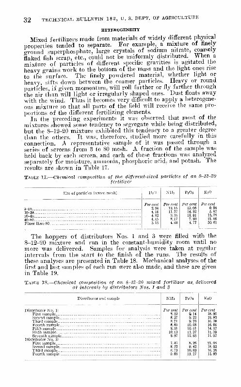
32 TECHNICAL BULLETIN 18 2, U. S. DEPT. OF AGEICULTUEE
HETEKOGENEITY
Mixed fertilizers made from materials of widely different physical properties tended to separate. For example, a mixture ot finely ground superphosphate, large crystals of sodium nitrate, coarsely flaked fish scrap, etc., could not be uniformly distributed. VV hen a mixture of particles of different specific gravities is agitated the heavy o-rains work to the bottom of the mass and the light ones rise to the surface. Tlie finely powdered material, whether light or heavy, sifts down between the coarser particles. Heavy or round particles, if given momentum, will roll farther or fly farther through the air than will light or irregularly shaped ones. Dust floats away witli the wind. Thus it becomes very difficult to apply a heterogene- ous mixture so that all parts of the field will receive the same pro- portions of the different fertilizing elements.
Ill the preceding experiments it was observed that most of the mixtures showed some tendency to segregate while being distributed, but the 8-12-20 mixture exhibited tliis tendency to a greater degree than the others. It was, therefore, studied more carefully in this connection. A representative sample of it was passed through a series of screens from 3 to 80 mesh. A fraction of the sample was held back by each screen, and each of these fractions was analyzed separately for moisture, ammonia, phosphoric acid, and potash. The results are shown in Table 17.
TABLE 17.—Chemical componition of the diffirent-sizcd particles of an 8-12-20 fcrtnizcr
Size of particles (screon mesh)
3-10 10-20 20-40 40-80 - Finer than 80
H.O NHj PlOj
Per cent Per cent Per cent 2.94 . 13.15 13.06 4.14 11.27 14.32 4 82 9.56 11.91 4.45 8.17 7.90 3.16 4.60 4.77
KiO
Per cent 0.94 6.87
13.78 21.06 30.61
The hoppers of distributors Nos. 1 and 3 were filled with the 8-12-20 mixture and run in the constant-humidity room until no more was delivered. Samples for analysis were taken at regular intervals from the start to the finish oí the runs. The results of these analyses are presented in Table 18. Mechanical analyses of the first and last samples of each run were also made, and these are given in Table 19.
TABLE 18.—Chemical composition of an 8-12-20 mimed fertilizer as. delivered at intervals by distributors Nos. 1 and 3
Distributor and sample
Distributor No. 1: First sample Second sample.. Third sample... Fourth sample,. Fifth sample Sixth sample Seventh sample.
Distributor No. 3: First sample Second sample.. Third sample..- Fourth sample..
NHî PfOt
Per cent Per cent 8.32 9.14 8.27 9.23 8.71 9.76 8.85 10 06 9.31 10 51
10.13 11.37 9.97 12.63
7.45 8.28 8 22 9.42 8.79 10 09 9.66 11.27
K,0
Per cent 18.06 19.80 16.70 16.00 14.37 11.39 11.97
21.08 18.02 16.26 13.00

MECHANICAL APPLICATION OF FEETILIZEE& 3» TABLE 19.—Mechanical analyses of the first and last portions of an 8-12-20
mixed fertiliser delivered froih distributors Nos. 1 and 3 during single runs
Distributor No. 1 Distributor No. 3
Size or particles (screen mosh) First
sample Last
sample First
sample Last
sample
3_10 Per cera
10.82 15.92 21.02 19.43 32.80
Per cent 26.63 25.17 20.40 11.67 16.32
Per cent 3.82
16.32 17.44 20.06 42.35
Per cent 10.49
jQ_20 - - 32.40 24.63 16.92 16.66
From these results it is clear that the tendency in both types of distributors was to deliver the finer particles first. With a mixture such as this, the composition of the fertilizer applied in one part of a field would be materially different from that in another.
This difficulty may be entirely eliminated by making a slurry of the components to be mixed and then graining them all together. This process probably would not be practical with low-grade mix- tures, but is entirely feasible with mixtures like nitrophoska.
SPECIFIC GRAVITY
Actual specific gravity is the ratio obtained by dividing the weight of a solid substance by the weight of water it will displace. The apparent specific gravity of a fertilizer is the ratio obtained by divid- ing the weight of a unit volume by the weight of an equal volume of water.
In this study apparent density or specific gravity is of more in- terest than absolute specific gravity because it varies witli the state of subdivision, moisture content, degree of packing, etc., while actual specific gravity remains the same.
In Table 20 are listed the apparent specific gravities of the experi- mental materials, together witli the weights and volumes of the vari- ous materials delivered per acre when they were at equilibrium in an atmosphere of 68° F. and relative humidities of 40, 60, and 80 per cent. These apparent specific-gravity determinations were made by filling a graduated cylinder to the 100 cubic centimeter mark, tapping it lightly on the bottom and again filling to the mark if necessary. The weight of this volume in grams was divided by 100 to obtain the apparent specific gravity. Each value in the table is the average of several such determinations.
In order that apparent specific gravity determinations may be com- parable, they must all be made in the same manner because greater degrees of packing give higher values. If a large volume—such as a bushel of material—had been weighed, values somewhat higher than those given in Table 20 would have been obtained in some cases.
The volumes delivered by distributor No. 1, as given in Table 20, were calculated from the actual weights delivered and the apparent specific gravities.
98734—30 3

34 TECHNICAL BULLETIN 18 2, U. S. DEPT. OF AGKICTJLTXTEE
TABLE 20.—Apparent speciflo gravity of fertilizers ani weight and volume deliv- ered iij distributor No. 1 at several relative humidities and at 68° F.
Apparent specific gravity and rate of fertilizer delivery at percentage rela- tive humidity of—
Fertilizer 40 60 80
Appar- ent
specific gravity
Delivery rate
Appar- ent
specific gravity
Delivery rate
Appar- ent
specific gravity
Delivery rate
Ordinary fertilizer materials: 0.977 .785
1.061 .909 .501 .601
Pounds per acre 102. 95 82.76
136.04 100.48 58.95 48. 35
Pints 105.37 105.42 127.27 110.64 117.66 80.44
116. 39
116. 39
113. 15 119. 47 101. 01 100.48
121.08 106. 01 128.60
108.78
119.21 133. 45 108.33
101. 21 107. 35 102.03 100.92
112.28 111.90 HI. 18
124. 56 109.60 102. 31 108. 38 117.81 110. 39
105. 64 90 35
110.74 110. 37 111.81 117.70
0.991 .785
1.064
""'.'499" .692 .781
.628
.673
.811
.788
.770
.880
.592
.898
.679
.983
.950
.838
.830
.724
.844
.816
.842
.799
.80S
.959
.800
.788
.953
.887
.834
.809
.698
.944
.970
.921
.803
Pounds per acre
93.05 69.12
112.09 (')
66.34 45.30 89.88
03.45
00.50 73.33 70.08 84.07
101. 20 59.63
111.51
67.66
105.27 115.43 77.54
78.55 73.33 81.31 61.13
82.18 94.38 55.32
96. 85 86.83 75. 79 93.94 90.00 89.59
82.33 33.84 91. 62 96. 99 90 31 78 99
Pints 94.60 88.05
105.35
0.922 .760
Pounds per acre
79.57 11.76 (') (')
63.14 5Z27 89.46
(') (0
65.63
90.76 6.82
106.58
63.31
85.38 86.83 28.17
1.89 8.13 9.16 (')
68 23 22.94 (')
(') 35.43 00 84 63.72 60 26
(') (') (')
33. 69 12.78 22.94 (')
Pints 86.30
Sulphate of ammonia 16.08
112.90 76.52
116.08
101.03
98.81 90.42 96.56
108.34
114. 22 100.56 124.17
116. 86
107.09 121. 50 92.63
94.64 101.28 96.34 75.01
97.60 118 12 68.46
100.99 108.64 96. 18 98.67
102.14 107. 42
101. 77 66. .59 97.08 99.98 98.06 98.37
.470
.623
.770
"'"."778"
.888
. 665
.895
.604
.954
.917
.702
1.073 .064 .748
.809
.794
"'"."775" .729 .861 .833
"".'6Ô8' .684 .722
ÎÏ3.Ô6 Cottouseed meal __ 99.94 Peat .789 91.04 116. 18
Concentrated fertilizer mate- rials:
.630
.693
.807
.874
.802
.867
.630
.901
.598
.983
.927
.961
.868
.729
.915
.833
.838
.846
.794
.960
.846
.799
.907
.896
.861
.944
.693
.948
.988
.935
.813
73.33
78.41 96.41 88 28 80 59
104.98 66.79
116.87
65.06
117.18 123.71 104.11
87.86 78. 26 93.36 84.07
94.09 94.67 88.28
118.34 92.64 81.76 98.30
105. 66 93.94
99.76 63.58
104.98 109.05 104.54 95.09
Urea ammonium phos-
Aramonium nitrate
84.36 Monoammonium phos-
102. 19 Diamraoniura phosphate- Triple superphosphate— Potassium ammonium
10 26 119.08
95.36 Monopotassium p h o s -
89.60 Potassium nitrate Trona potassium chloride.
Ordinary mixtures, commer. cial:
2-8-6
94.68 30.97
1.76 3-9-3.. 12.43 4-8-4 .__ 12.23 9-0-6
High analysis mixtures, com- mercial:
4-10-6 71.98 10-8-10 28.89 12-6-2
Concentrated mixtures, com- mercial:
0-20-20 45.72
4-24^ -.- 8-12-20
83.45 62.39
8-16-8 - 10-16-14
72.34
Special: (No 1) 14-42-14 (No. 2) 14-43-14 (No. 3) 13-39-13 -. (No. 4) 1.3-;i9-13 (No. 5) 13-41-13 (No. 6) 17-26-17
"'6Ö."43 18.68 31.77
Average .832 92.45 111.00 .812 81.13 99.60 .772 47.99 02.23
1 Undrllîable due to absorption of moisture.
The effects of moisture, size of particles, and other factors com- plicate a comparison of the delivery rates, as shown in Table 20. However, considering only the values obtained with materials at equilibrium with an atmosphere of 40 per cent relative humidity, in which the effect of other factors is least, a much greater variation in delivery rate is seen when measured by weight than when measured by volume. The weights range from 48 to 135 pounds per acre (mean 92.4o±2.05), and the volumes from 80 to 133 pints per acre

MECHANICAL APPLICATION OF FERTILIZERS 35
(mean 111.00±0.52). The standard deviations of the delivery rates by weight and by volume are 18.73 and 4.76, respectively. Thus it is^ evident that much of the difference in these delivery rates, when figured by weight per acre, is due to the apparent specific gravity of the fertilizer. This effect is noticeable, however, only when the materials are dry, as it is masked by other factors when the materials are damp.
Inasmuch, then, as delivery rate is more accurately gaged when figured in pints, calibration charts, if given, should be expressed in pints per acre.
FRICTION BETWEEN PARTICLES
The kinetic angle of repose of any substance is the angle with the horizontal at which the substance will stand when poured into a pile. The tangent of this angle is a measure of the resistence to flow and is called the kinetic coefficient of friction. It can be shown that in the case of a substance having a kinetic angle of repose greater than 45° no free flow can occur. Slopes steeper than 45° can, of course, be obtained with some substances, but only with those whose particles adhere by reason of stickiness or from some other cause. It should not be concluded, however, that no delivery could be made of a fertilizer having an angle of repose greater than 45°. Fairly satisfactory results may be obtained with materials having a somewhat greater angle; this is due both to the positive action of the dispensing mechanism and to the fact that under the pressure imposed by the material above, the fertilizer in the bottom of the hopper may actually flow from that cause alone.
The angle of repose of a fertilizer may bo measured by slowly pouring a gallon or so of it into a heap upon a level surface, being careful to keep the pouring edge of the vessel just above the center of the pile. The angle with the horizontal may then easily be deter- mined with a protractor; or if the height of the pile is divided by its radius, the kinetic coefficient of friction will be obtained. The apparatus used in this work for measuring the angle of repose is illustrated in Plate 6, B. It may be described as one corner of a rectangular box whose perpendicular sides are 10 inches in height. The sides and bottom of the box were graduated in degrees of angles with the horizontal. The graduations on the sides were radiuses drawn from a common point where the inner top edges of the sides meet. Tlie graduations on the bottom were concentric arcs of circles joining corresponding graduations of the two sides.
In conducting a test the box was carefully leveled and the ferti- lizer materials were poured into it at the apex formed by the gradua- tions on the side until the mass of fertilizer piled up exactly to this apex, as illustrated in Plate 6, B, which shows the instrument con- taining potassium phosphate ready for reading. The angle of repose was then read on the three graduated scales. "With all materials with angles of repose of less than 45°, the readings on the three scales were usually identical and could be duplicated at a later date to within half a degree. As the readings approached 55° they became progressively less reliable.
The kinetic angle of repose was determined for 22 selected ferti- lizers under various temperature and relative humidity conditions, as shown in Table 21. Different materials were found to have very different angles of repose at the same relative humidity. It will

36 TECHNICAL BULLETIN 182, U. S. DEPT. OF AGKICULTURE
be observed that in the majority of cases the angle of repose increases more or less as the relative humidity increases above 40 per cent, and that this feature is more pronounced at relative humidities or 60 and 70 per cent. No results are given for 80 or 90 per cent rela- tive humidity because in most cases consistent results could not be obtained; with few exceptions the angles determined were greater than 50°.
By comparing Tables 6, 9, and 21, it will be observed that rates of delivery and angles of repose are inversely correlated. When the delivery rates by weight of all fertilizers having the same angle of repose were averaged, and the delivery weight correlated with angle of repose, the correlation coefficient was as follows :
r=-0.928 + 0.019.
When the rates in pints per acre were correlated with the angles of repose of the same materials the following coefficient was obtained :
r=-0.970 ±0.008.
In this case the correlation is as nearly perfect as one could expect to achieve with an experimental instrument as crude as a grain-drill fertilizer attachment. It therefore appears justifiable to derive formulas for calculating the delivery rate of a fertilizer from its angle of repose.
TABLE 21.—Kinetic anyles of repose of fertilizer materials at aiffercnt relative humidities and at different temperatures
Angles of repose at—
Fertilizer Percentage rela- tive humidity
(SO" F.) of—
Percentage relative humidity (68° F.) of—
Percentage relative humidity (86° F.) of—
50 60 70 40 50 60 70 30
De- grees 38 40 35 42 35
34 41 37 37 39 36
40 44
37 35 35
37 37 38
35 35 38
40 60 60
Ordinary fertilizer materials: De-
grees 37 38.5 37.5 40.5 34
36 42 38 37.6 41 38
42 42
35 35 35
38.5 40.5 38
35.6 37 37
De- grees 38 40 37 41 35
36 43.5 41 37 40 39
40 44
36 35 34.5
38.6 40 38
35 36 5 36.5
De- grees 42 63 47.6 41.6 36
38.5 52 46.6 37.6 41.6 40
43 46
36.5 36.5 36.5
39 38 42
35 37 35.5
De- grees 36 40 36 42 36
36 42.6 37 38 40.6 39
42 43
36 36.5 35.5
37 42 37
36 37 38
De- crees 39 42 37 40.6 36
35.6 60 44 37 40.6 39
41 46
36 36 37
39 40 46
36 36 37.6
De- grees 40 49.6 51 41 35.6
37 64 48 38 40.5 38
43 47
36 38 43
42 39.5 47
36 37.6 36.6
De- crees 40 64 (')
40.6 36
46 (') (')
38 5 43 45
49 (')
39 40 45
43.5 40
(■)
40 38 37
De- grees 37 40 37 40.6 34
35 44.5 40 37.6 39 38
37 45.5
37.6 37 36.6
38 37 39
35 35 36
De- grees 37 47 47 40.6 35.5
37 60 46 37 41 41
41 47
38.6 37 42
40.6 40.6 44
36.6 37 37
De- grees
39.5 47 61 40.6
Peat 36.6 Concentrated materials:
37 XJrea ammonium phosphate-. 63
60 Monoammonium phosphate.. Monopotassium phosphate..
37 41 41.5
Ordinary mixtures, commercial: 3-9-3 42 ÎH>..6 47
Special: No. 1, 3-9-3 38.6 No 2, 3-9-3 37 No. 3, 3-9-3 - --- 42
High-analysis commercial mix- tures:
4-10-fl - - 40.6 40
12-6-2 48 Concentrated commercial mix-
tures: 0-20-20 36.5 8-16-8 - 37 8-12-20 — 37
I Material too damp to make a satisfactory determination.

MECHANICAL APPLICATION OF FEETILIZEES 37
At present sufficient data are available for deriving a formula for distributor No. 1 when the gate lever is set on notch No. 10. Deliv- ery rates in pounds stated in Tables 6 and 9 were translated into pints according to apparent specific gravities shown in Table 20 and cor- related with angles of repose given in Table 21. The average deliv-
er JO" J'f" "^0° ^o"
FiGUUE 10.—Correlation between average delivery rates of distributor No, 1 and angle of repose
ery rate for each angle of repose is plotted in Figure 10. The equation representing the line of closest fit is as follows :
y=257.18-3.78«,
where y is the delivery rate per acre in pints while the distributor is operating at slow speed, and x is the angle of repose of the fertil- izer in degrees. For fast-speed gear the following equation would be used :
.y = 18.2 (67-a;)
According to these formulas a fertilizer with an angle of repose of 25° should have a delivery rate 321 per cent of that of a feutilizer with an angle of 54°.
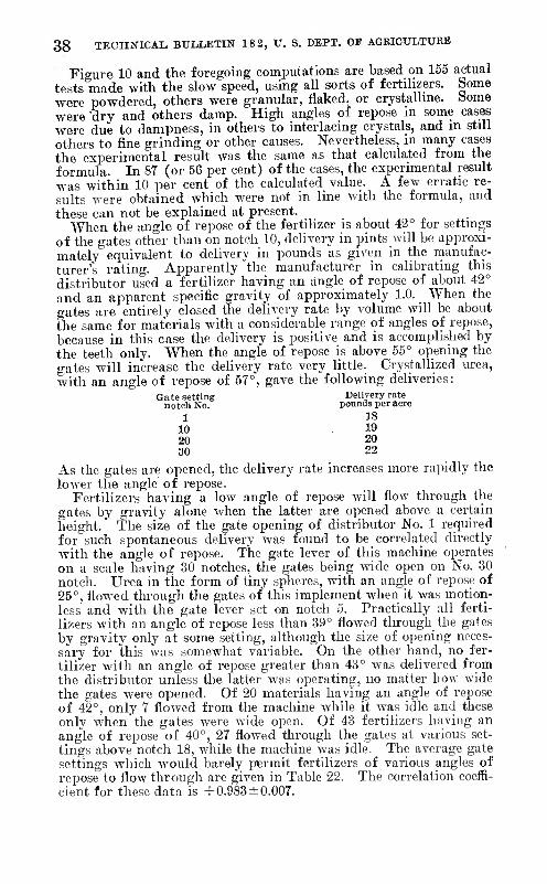
38 TECHNICAL BULLETIN 18 2, U. S. DEPT. OP AGEICULTUEB
Figure 10 and the foregoing computations are based on 155 actual tests made with the slow speed, using all sorts of fertilizers. Some were powdered, others were granular, flaked, or crystalline. Some were dry and others damp. High angles of repose in some cases were due to dampness, in others to interlacing crystals, and in still others to fine grinding or other causes. Nevertheless, in many cases the experimental result was the same as that calculated from the formula. In 87 (or 56 per cent) of the cases, the experimental result was within 10 per cent of the calculated value. A few erratic re- sults were obtained which were not in line with the formula, and these can not be explained at present.
When the angle of repose of the fertilizer is about 42° for settings of the gates other than on notch 10, delivery in pints will bo approxi- mately equivalent to delivery in pounds as given in the manufac- turer's rating. Apparently the manufacturer in calibrating this distributor used a fertilizer having an angle of repose of about 42° and an apparent specific gravity of approximately 1.0. When the gates are entirely closed the delivery rate by volume will be about the same for materials with a considerable range of angles of repose, because in this case the dehvery is positive and is accomplished by the teeth only. When the angle of repose is above 55° opening the gates will increase the delivery rate very little. Crystallized urea, with an angle of repose of 57°, gave the following deliveries:
Gate setting Delivery rate noteli No. pounds per acre
1 18 10 19 20 20 30 22
As the gates are opened, the delivery rate increases more rapidly the lower the angle of repose.
Fertilizers having a low angle of repose will flow through the gates by gravity alone when the latter are opened above a certain height. The size of the gate opening of distributor No. 1 required for such spontaneous delivery was found to be correlated directly with the angle of repose. The gate lever of this machine operates on a scale having 30 notches, the gates being Avide open on No. 30 notch. Urea in the form of tiny spheres, with an angle of repose of 25°, flowed through the gates of this implement when it was motion- less and with the gate lever set on notch 5. Practically all ferti- lizers with an angle of repose less than 39° flowed through the gates by gravity only at some setting, although the size of opening neces- sary for this was somewhat variable. On the other hand, no fer- tilizer with an angle of repose greater than 43° was delivered from the distributor unless the latter was operating, no matter how wide the gates were opened. Of 20 materials having an angle of repose of 42°, only 7 flowed from the machine while it was idle and these only when'the gates were wide open. Of 43 fertilizers having an angle of repose of 40°, 27 flowed through the gates at various set- tings above notch 18, while the machine was idle. The average gate settings which would barely permit fertilizers of various angles of repose to flow through are given in Table 22. The correlation coeffi- cient for these data is +0.983±0.007.

MECHANIOAIi APPLICATION OF FERTILIZERS 3»
TABLE 22—Average cate setting of distributor No. 1 at or above which spon- taneous delivery occurred for fertilizers having given angles of repose
Angle of reposo (degrees)
25 29, 34 35 36 37,
Ferti- lizers
having tlie given
angle
Number 1 1 4
34 44 52 34
Average gate set-
ting
6 13
10.7±3.7 17. 2±3. 2 18.0±3.0 20.7±7.3 21.8±5. 2
Angle of repose (degrees)
Ferti- lizers
having the given
angle
Average gate set-
ting
39.. 40.. 41.- 42.. 43.. 44-t-
Number 24 43 23 20 11 67
I
24.6±6.6 26.9±7.8 26.8±8.8 27.4±6.4 29.9±0.9
(')
1 No spontaneous delivery at any gate opening.
The effect of head is greatest with materials having the lo^vest angle of repose. In the case of distributor No. 1 an incr'ïase of 4 inches in depth in the hopper of spherical pellets of potassium nitrate liaving an angle of repose of 29° increased the delivery rate 15 per cent. The same increase in head of this material in the form ot 20-40 mesh crystals with an angle of repose of 36° increased the delivery- only 6 per cent. When the latter fertilizer was damp and had an angle of repose of 54° the same increase in head caused less than 1 per cent increase in delivery rate.
The uniformity with which a given fertihzer can be distributed decreases regularly as its angle of repose increases. In these experi- ments all materials with an angle of repose greater than 50° issued from the delivery tubes very irregularly, and usually in lumps of varying sizes. When the angle of repose exceeded 55° the fertilizer was practically undrillable.
Thus the angle of repose of a fertilizer is a fair indication of {!) the rate of delivery, (2) the size of gate opening through which it will escape when the distributor is not operating, (3) the extent of variations in delivery caused by changes in depth of fertilizer in the hopper, and (4) the uniformity with which a fertilizer can be applied with distributor No. 1. When each of these four points was taken into consideration for all circumstances that might arise fer- tilizers with an angle of repose between 40° and 45° were found most satisfactory with this machine. If no more than 500 pounds of fertilizer were to be applied to the acre and the liopper were Ifept well filled, better results would be obtained with materials having an angle of repose between 35° and 40°. Theoretically, the best results could be obtained with a distributor especially designed for fertilizers having the lowest angle of repose. However, present dis- tributors were designed to handle the average materials now in use which have angles of repose of about 40°, and consequently in some cases are not quite as satisfactory with materials of best drillability.
The angles of repose and kinetic coefficients of friction for most of the fertilizers used in this study, when at equilibrium with a rela- tive humidity of 40 per cent, are given in Table 23.
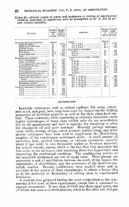
40 TECHNICAL BULLETIN 18 2, TJ. S. DEPT. OF AGRICULTURE
TABLE 23.-~Kinetic angles of repose and ooefïicîents of f''^^{'^?::>f^^ZV^^^ fertilizer materials at equiUhrium with an atmosphere of 86 F. ana 40 per cent relative humidity
Ordinary fertilizer materials: Superphosphate,. --- Sulphate of ammonia Nitrate of soda Nitrate of lime Fish scrap - Cottonseed meal - Peat -
Concentrated materials: Urea, granulated Úrea, powdered Urea ammonium phosphate. Ammonium nitrate - Leunasalpter Ammo-phos.._ — Monoammonium phosphate., Diammonium phosphate Triple superphosphate- Potassium ammonium phos-
phate. Monopotassium phosphate.. Potassium nitrate Trona potassium chloride—
Ordinary mixtures, commercial: 2-8-5 - 3-9-3 4-8-4 - 9-0-6 -
Kinetic
of repose
37 39 45.5
Kinetic coeffi-
cient of friction
egrees 37 0.7M 4n .839 37 .754 41 .869 ■tas .854 47 S 1.091 34 .675
35 .700 43 .933 44 5 .983 4n .839 3S 5 .796 37 .764 37.,') .767 3fi. ñ .740 37 .754
43 .933 39 .810 3S .781 37 .764
.781
.754
.810 1.018
Special: No. 1, 3-9-3 No. 2, 3-9-3 No. 3, 3-9-3
High-analysis mixtures: 4-10-6 - 10-8-10 - 12-6-2 -
Concentrated mixtures, commer- cial:
0-20-20 - 4-16-10 4-16-20 4-24-4 -■ 8-12-20 8-16-8 - 10-16-14
Sp«3ial: No. 1, 14^2-14 No. 2, 14-43-14 No. 3, 13-39-13...- No. 4, 13-39-13 No. 6, 13-41-13 No. 0, 17-26-17
Kinetic angle
of repose
Degrees 37.6 37 36.6
38 37 39
35 36.5 37 36.5 36 35 36
48 40
39 39.5
Kinetic coeffi- cient of friction
0.767 .764 .740
.781
.754
.810
.700
.740
.754
.740
.726
.700
.727
.824 1.111 .839 .781 .810 .824
CONDITIONERS
Insoluble substances, such as animal tankage, fish scrap, cotton- seed meal, and peat, have long been used for improving the drilling properties of fertilizer mixtures as well as for their plant-food con- tent. These materials, while containing at ordinary humidities much higher percentages of water than soluble salts do, are nevertheless dry to all appearances and have a capacity for remaining so after the absorption of still more moisture. Kecently garbage tankage, cocoa shells, sewage sludge, castor pomace, leather scrap, and other similar substances have been used to supplement the diminishing supplies of the conditioners mentioned above. A small amount of ammonia, hme, ground limestone, or calcium cyanamide (usually about 2 per cent) is also frequently added to fertilizer mixtures, for several reasons, among which is the fact that they neutralize the free acids in tlie mixtures, thus rendering them less hygroscopic and improving the mechanical condition. The conditioning powers of the materials mentioned are not of equal value. Their present use represents a sort of equilibrium between the needs of the farmer, the capabilities of distributors, and the economics of the fertilizer-ma- terials market. Several conditioners were studied alone and in mixtures in the course of these experiments, to obtain a better idea as to the necessity or desirability of adding them to concentrated fertilizers.
A mixture was prepared having the same composition as the com- mercial 3-9-3 used in these experiments, except that it contained no organic ammoniate. It was then divided into three equal parts, one of which was used as a check mixture, while to the other two 13.3 per

MECHANICAL APPLICATION- OF FEETILIZEES 41
cent of conditioner was added, in the form of fish scrap and peat, respectively. The composition and mechanical analyses of these mix- tures are given in Tables 3 and 4. No. 1 distributor was used with gate lever at notch 10.
The results obtained with these mixtures, when at equihbrmm with various temperatures and relative humidities, are given in Table 2-i and shown graphically in Figure 11. The delivery rates obtained with the commercial 3-9-3 mixture are given in Table 25. In com- paring these two tables it must be borne in mind that while the com- mercial 3-9-3 fertilizer was made of the same kinds of ingredients, except that the conditioner was cottonseed meal, it was prepared at a different time, and is therefore not strictly comparable with the other three mixtures.
30 50 60 70 Per cent relative humidity
FIGURE 11,—Effect of conditioners upon delivery rate
In Table 6 the delivery rates of peat, cottonseed meal, and fish scrap were shown to vary less with changes in relative humidity than any other fertilizers used in the experiments, except potassium- ammonium phosphate. The cottonseed meal and fish scrap both de- cayed when kept in a relative humidity of 90 per cent, but no spoil- age was observed at 80 per cent.
TABLE 2i.->—Effect of peat and fish-scrap conditioners upon delivery rate of fertilizer mixtures at equilihrium under various atmospheric conditions
Conditioner Tem- pera- ture
Rate (pounds per ñcre) and water content (per cent) at percentage relative humidity of—
30 60
None
Peat..
Fish scrap.
£6«. per acre
k08. 32
103. 38
^102. 07
Per cent
0.26
Lbs. per acre
101. 78
102.80
101. 78
Per cent
0..30
1.44
.91
Lba. per acre
94.67
96.98
Per cent
2.20
1.53
Lbs. per acre 67. 40 57.02 54.97 '82. 31 73.39 64.47 [S2.46 74. 27 [69. 45
Per cent 1.10 1.81 2.31 2.37 2.96 3.35 2.00 2.40 2.95
Lbs. j per ! Per acre cent
■56. 61
•65. 76
13.
4.97
6.56
6.05
Lbs. per acre
65.85
57.46
61.65
Per cent
16.99
15.21
14.68
Lbs. per acre
12.43
24.66
26.44
Per cent
26.76
21.66
20.67
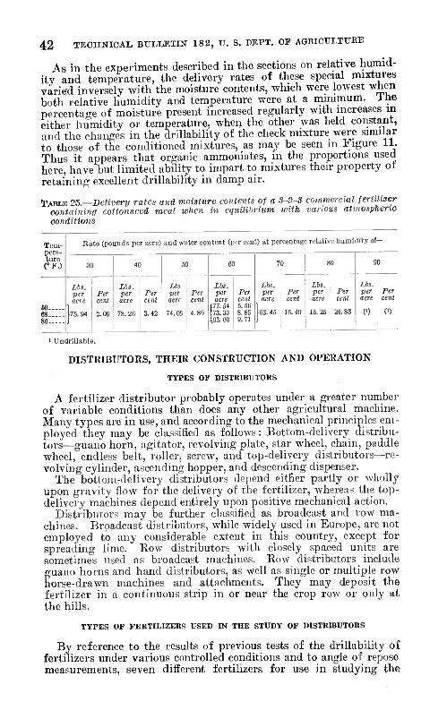
42 TECHmCAL BULLETIN 18 2, U. S. DEFT. OF AGEICULTXTBB
As in the experiments described in the sections on relative humid- ity and temperature, the delivery rates of these special mixtures varied inversely with the moisture contents, which were lowest when both relative humidity and temperature were at a minimum. I he percentage of moisture present increased regularly with increases m either humidity or temperature, when the other was held constant, and the changes in the drillability of the check mixture were similar to those of the conditioned mixtures, as may be seen in Figure 11. Thus it appears that organic ammoniates, in the proportions used here, have but limited abiUty to impart to mixtures their property ot retaining excellent drillability in damp air.
TABLE 25.—Delivery rates and moisture contents of a 3-9-3 commercial fertilizer containing cottonseed meal when in equilibrium with various atmospheric conditions
Tem- pera- ture CF.)
Rate (pounds per acre) and water content (per cent) at percentage relative humidity ot -
30 40 60
Lbs per Per acre cent
74.05 4. 89
60 70 80 00
60 68 86
Lb!. per acre
76.94
Per cent
2.06
Lbs. per acre
78.26
Per cent
3.42
Lbs. per acre 77.54
m. 33 63.60
Per cent 5.66 8.86 9.71
£65. per acre
63.46
Per cent
16.40
Lbs. per acre
15.25
Per cent
24.83
Lbs. per acre
(')
Per cent
(')
' Undrillable.
DISTRIBUTORS, THEIR CONSTRUCTION AND OPERATION
TYPES OF DISTRIBUTORS
A fertilizer distributor probably operates under a greater number of variable conditions than does any other agricultural machine. Many types are in use, and according to the mechanical principles em- ployed they may be classified as follows: Bottom-delivery distribu- tors—guano horn, agitator, revolving plate, star wheel, chain, paddle wheel, endless belt, roller, screw, and top-delivery distributors—re- volving cylinder, ascending hopper, and descending dispenser.
The bottom-delivery distributors depend either partly or wholíy upon gravity flow for the delivery of the fertilizer, whereas the top- delivery machines depend entirely upon positive mechanical action.
Distributors may be further classified as broadcast and row ma- chines. Broadcast distributors, while widely used in Europe, are not employed to any considerable extent in this country, except for spreading lime. Kow distributors with closely spaced units are sometimes used as broadcast machines. Kow distributors include guano horns and hand distributors, as well as single or multiple row horse-drawn machines and attachments. They may deposit the fertilizer in a continuous strip in or near the crop row or only at the hills.
TYPES OF FERTILIZERS USED IN THE STUDY OF DISTRIBUTORS
By reference to the results of previous tests of the drillability of fertilizers under various controlled conditions and to angle of repose measurements, seven diiïerent fertilizers for use in studying the

MECHANICAL APPLICATION OF FEETILIZEES 43
distributors were selected and maintained under such conditions that they represented a series of different degrees of drillability. If 100 be arbitrarily chosen to represent perfect drillability, and 0 to rep- resent poorest drillability or that of a fertilizer which could not be drilled by ordinary means, then the relative numerical score for the drillability of each selected fertilizer is defined as follows :
Score 95 : Hard spherical particles flowing with exceptional uni- formity and with only the slightest resistance, flowing more freely than dry sand. Fertilizer selected, sprayed potassium nitrate, 20 to 40 inesh, maintained under atmospheric conditions of 50 per cent relative humidity. Angle of repose, 28°.
Score 85: Granulated particles somewhat irregular in shape, flow- ing with a considerable degree of uniformity, flowing like coarse, dry sand. Fertilizer selected, potassium-ammonium phosphate, 10 to 20 mesh, maintained under atmospheric conditions of 70 per cent relative humidity. Angle of repose, 35°.
Score 75 : A mixture of various sizes of irregularly shaped parti- cles, breaking down and flowing readily, although there is a notice- able tendency for the finer material to adhere in small lumps, flowing somewhat like slightly moist, pulverized soil. Fertilizer selected, 4-8-4 commercial mixture, maintained under atmospheric conditions of 70 per cent relative humidity. Angle of repose, 42°.
Score 65 : A mixture of large jagged particles, light strawlike mate- rial, and fine particles, flowing quite freely when broken up, but readily matting together into a mass. Fertilizer selected, fish scrap (different sample from that used in previous experiments) main- tained under atmospheric conditions of 70 per cent relative humidity. Angle of repose, 48°.
Score 55 : Powdered material appearing to be slightly damp and partially retaining its form when squeezed in the hand ; not flowing much by gravity unless continually agitated and tending like flour to flow in lumps unless mechanically separated. Fertilizer selected, potassium-ammonium phosphate, maintained under atmospheric con- ditions of 70 per cent relative humidity. Angle of repose, 54°.
Score 35 : A mixture of various sizes of particles of which none are very large, appearing to be damp and retaining its form when compressed in the hand, flowing by gravity only by breaking down in lumps, having a loose or porous texture when thoroughly agitated and divided mechanically. Fertilizer selected, concentrated mixture No. 4, maintained under atmospheric conditions of 80 per cent rela- tive humidity.
Score 15 : A mixture of various sizes of particles very damp, form- ing a soft mass similar to heavy mud except that it is not so sticliy, under pressure flowing to some extent as a semisolid, under ordinary means of agitation separable into very large lumps. Fertilizer se- lected, mixture 10-8-10, maintained under atmospheric conditions of 90 per cent relative humidity.
Although the different stages of drillability are represented above by different kinds of fertilizers under specific conditions, it is be- lieved that in general those selected represent any stages of drilla- bility which are likely to be found among the various classes of fertilizer materials and mixtures.
44 TECHNICAL BULLETIN 18 2, U. S. DEPT. OF AGRICULTTJEE
EXPERIMENTAL PROCEDURE
Ten different fertilizer distributors were tested with the selected fertilizers mentioned above. The time required for conducting the tests was so great that not only was the number of fertilizers and distributors limited, but also the number of tests on each distributor. The distributors represent several general tj'pes of machines com- monlj' used and will be described in detail. The study was made with the idea of determining the performances and limitations of types of machines, rather than of discovering the mechanical im- perfections of individual machines.
Distributors, representative of various types were opei-ated ancl tested to show the relationship of construction and principle of operation to evenness of distribution and control of delivery rate. The tests on uniformity of distribution not only showed the nature of delivery and extejit of variations for each distributor, but also were a means of determining the causes of variations in delivery and the relation of the drillability of a fertilizer to rate of delivery. This phase of the study also permitted conclusions to be drawn with respect to the limitations for satisfactory operation, case of opera- tion and control, and fineness of adjustment.
Uniformity of distribution was studied at 1-foot intervals of the travel of the distributor. This interval was chosen for several reasons: (1) Many plants are grown at intervals of 1 foot or less; (2) the root systems of many plants confine themselves to comiiara- tively small areas; (3) the diffusion of plant food from artificial fertilizer in the soil may extend only a few inches in a horizontal plane ; and (4) it has been found that fertilizer must be applied near the plant to be of maximum benefit dui-ing the immediate season.
The tests could not be conducted in the constant-humidity room, owing to insufficient space. Since previous tests had shown that rate of delivery was affected very little by ordinary changes of temperature, no attempt was made to control the temperature ex- cejjt in cases where it was necessary in maintaining approximately a desirable relative humidity. A hygrothermograph in the laboratory showed that the relative humidity conditions at all times agreed closely with those under which the fertilizers were stored. The fertilizers were stored under controlled conditions and were exposed to atmospheric conditions only while being used for the tests. Con- sidering the nature of the tests and the magnitude of tlie variations found, the brief exposure of the fertilizers to slightly different at- mospheric conditions during the tests would have little or no effect on the conclusions to be drawn from the study. The series of tests with sprayed potassium nitrate was conducted during cold weather when the relative humidity of the air in the slightly heated labora- tory remained almost constant at 50 per cent.
The manner of conducting the tests was as follows : The dis- tributor was given a charge of fertilizer and operated until the fertilizer was flowing normally. The distributor was then drawn over a wooden floor through a distance varying from 20 to 3.5 feet, the fertilizer being deposited on a strip of paper. The paper was stretched smoothly and tacked securely to the floor to eliminate any irregularities or motion of the paper which might cause some move- ment of the fertilizer after being deposited. The paper was ruled to facilitate accurate division of the fertilizer at 1-foot intervals.

MECHANICAL APPLICATION OF FERTILIZEES 45
The fertilizer delivered at each interval was weighed on a sensitive laboratory balance.
The position of the rotating parts of the distributing mechanism was noted at the end of each test, enabling their corresponding position to be readily determined for every interval of delivery. Allowance was made for the slight difference between discharge of the material into the delivery tube and actual delivery from the tube. In all instances with the fertilizers of better drillability, variations were due primarily to the imperfect construction or principle of operation of the machine. After each test was completed and the variation in delivery noted, the position of the distributing mechan- ism for every abnormal flow of fertilizer was studied and further tested to determine positively the cause of such deviations. The distributing mechanism of the machines either revolved or was actuated by one or more revolving parts, thus producing one or more cycles of delivery for each machine. Slight variations in the rate of travel and vibrations of the machines had some effect on the de- livery but were negligible in comparison to other causes of varia- tion. Fertilizers with poorer drillability passed through the dis- tributors so irregularly that in many instances deviations caused by the machine itself were obscured.
The distributors usually were adjusted to deliver approximately 25 per cent of their capacity. The setting of each machine remained the same throughout the series of tests, except as indicated in cases where additional tests were desirable. Where the distributor had several similar distributing units only one unit was used.
Since all distributors deliver fertilizer by volume rather than by weight, comparison of results on rate of delivery should be made on the basis of volume. The relative delivery rates, maximum and minimum deliveries per foot, and average per cent deviations in de- livery for each of the distributors and fertilizers represented are given in Table 26.
TABLE 26.—Delivery of fertilizers representing seven stages of drillability by various types of distributors
Ferti- lizer
Description ol delivery
Distributor number and distance between rows
drill- ability score
No. 1, 7 inches
No. 2, 8 inches
No. 3, 38 inches
No. 4, 38 inches
No. 6, 38 inches
4.')2 666
4.52 1.91
622 764
9.45 1.57
914 1,122
60.19 29.11
]
(') (') Minimum, grams per foot
■1
23.37 38.38 12.94
Rate, pints per acre 384 270
2.98 .67
652 388
4.81 .88
994 699 29.74 18.91
2,460 1,722
71.92 46.70
2,083 1,464 Rate, pounds per acre
Maximum, grams per foot ._ 28.86 20.03
Average per cent deviation 34.42 39.86 12.44 6.99 7.29
342 272
2.94 .84
479 381
4.48 1.30
. 807 624 26.13 16.16
1,193 950 43.68 13.16
1,790 1,425
76 28.82 Minimum, grams per foot 17.58
33.96 24.94 12.21 24.15 9.87
' Unrestricted flow. No results recorded.

46 TECHNICAL BULLETIN 18 2, U. S. DEPT. OF AGEICULTUKE
TABLE 26. Delivery of fertilizers representing seven stages of drillaUlity bv various types of distributors—Continued
Ferti- lizer drill-
ability score
Description of delivery
Distributor number and distance between rows
No. 1, 7 inches
Rate, pints per acre 435 Rate, pounds per acre..- - ; 239 Maximum grams per foot - -- 2.46 Minimum grams per foot - i -50
Average per cent deviation ¡ 36.95
Rate, pints per acre Rate, pounds per acre Maximum grams per foot. Minimum grams per foot-
2.64 .28
Average per cent deviation.. 42.15
Rate, pints per acre Rate, pounds per acre Maximum grams per foot. Minimum grams per foot..
45 31 1.35 .00
Average per cent deviation 112.72
Rate, pints per acre Rate, pounds per acre Maximum grams per foot. Minimum grams per ioot..
{')
Average per cent deviation..
No. 2, 8 inches
437 240
4.01 .78
40.38
403 216
3.13
19 13
.37
.005
(»)
No. 3, 38 inches
612 336
14.67 6.94
18.66
386 205
16.01 2.68
33.21
674 461 28.91 ! 6.06 ;
No. 4, 38 inches
1,812 995 40.32 25.41
9.62
477 264 19.21 1.60
61.34
306 209
17.80 .19
1.22 I 63.27
164 122 13.17
.08
76.65
No. 6, 38 inches
1,612 885
16.96 11.17
9.61
873 24.39 8.20
17.66
1,102 754 20.49 2.23
29.11
640 508 66.34
.00
152.61
Ferti-
Description of delivery
Distributor number and distance between rows Avemge deviation
Uzer drill-
ability score
No. 0, 42 inches
[
'Ïi-J- 1 No. 8, inches ! ^2 inches
No. 9, 42 inches
No. 10, 42 inches
for dis- tributors
tested (per cent)
194 238
9.81 7.67
134 166
7.38 4.17
414 609
Maximum grams per foot Minimum grams per foot-
Average per cent deviation.
(') 36.11 7.64
(') 96
6.3 11.06 46.28 22.88
122 86 3.88 2.56
730 131 613 92
17.67 , 3.94 11.16 ; 2.62
307 216
12.26 4.24
798 661 39.03 6.66
Maximum grams per foot Minimum grams per foot
Average per cent deviation.
86
10.05 9.16 1 8.13 21.33 63.65 20.33
176 140
6.32 4.04
6.12 1 131 ¡ 133 ! 761 619
19.31 9.66
104 : 106 6.09 ! 5.93 2.78 1 1.70
606 41.19 8.33
Maximum grams per foot Minimum grams per foot
Average per cent deviation.
76
10.81 16.06 11.79 I 31.16 36.29 21.02
120 66 3.21 1.87
634 293
11.94 6.08
131 1 163 72 ; 84
647 355 22.78 4.62
Maximum grams per foot Minimum grams per foot.
Average per cent deviation.
4.36 1.48
4.46 1.29 66
10.49 12.86 29.39 25.61 45.77 23.90
169 413 220
11.02 2.71
131 ' 131 70 i 70
709 378 28.26 6.66
on 4.96 1.22
3.97 1.11 55 Minimum grams per foot
Average per cent deviation.
.79
36.64 28.42 31.99 25.07 30.38 32.80
1 Unrestricted flow. No results recorded. ■No delivery.
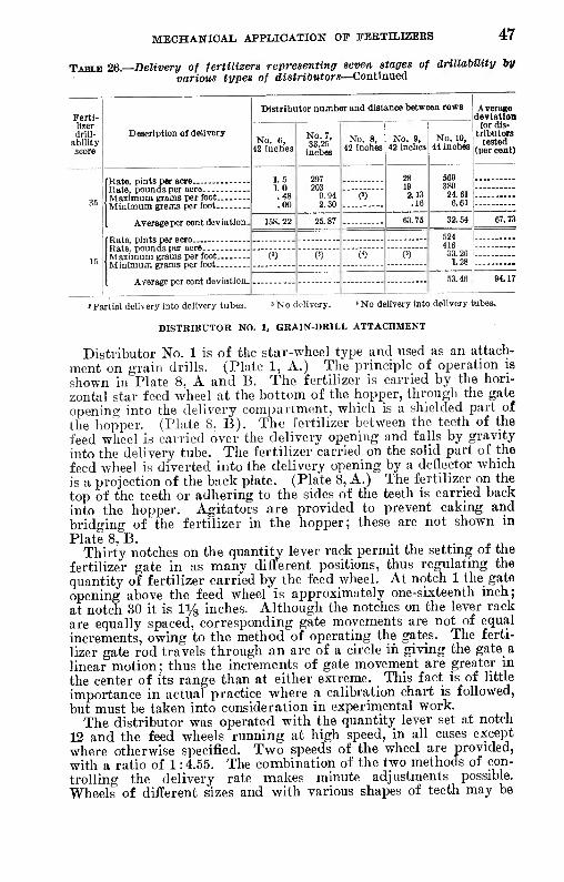
MECHANICAL APPLICATION OF FEBTILIZEES 47
TABLE 26.—Delivery of fertilizers representing seven stages of drillaUlity lyy various types of distributors—Continued
Ferti- Distributor number and distance between rows Average
deviation lizer drill-
ability score
Description of delivery No. 6,
42 inches
No. 7, 33.26
inches
No. 8, 42 inches
No. 9, 42 inches
No. 10, 44 inches
for dis- tributors
tested (per cent)
l.S 1.0 .48 .00
297 203
9.94 2.30
28 19 2.13 .16
569 389 _
Maximum grams per foot Minimum grams per foot
Average per cent deviation.
m 24.61 6.61 35
158.22 25.87 03.75 32.64 67.73
624 416 33.20
1.28 Maximum grams per foot Minimum grams per foot. -
(») (') (') « 15
Average per cent deviation- 53.46 94.17
> Partial delivery into delivery tubes. 8 No delivery. < No delivery into delivery tubes.
DISTRIBUTOR NO. 1, GRAIN-DRILL ATTACHMENT
Distributor No. 1 is of the star-wheel type and used as an attach- ment on grain drills. (Plate 1, A.) The principle of operation is shown in Plate 8, A and B. The fertilizer is carried by the hori- zontal star feed wheel at the bottom of the hopper, through the gate opening into the delivery compartment, which is a shielded part of the hopper. (Plate 8. B). The fertilizer between the teeth of the feed wheel is carried over the delivery opening and falls by gravity into the delivery tube. The fertilizer carried on the solid part of the feed wheel is diverted into the delivery opening by a deflector which is a projection of the back plate. (Plate 8, A.) The fertilizer on the top of the teeth or adhering to the sides of the teeth is carried back into the hopper. Agitators are provided to prevent caking and bridging of the fertilizer in the hopper; these are not shown in Plate 8, B. . . t.
Thirty notches on the quantity lever rack permit the setting of the fertilizer gate in as many different positions, thus regulating the quantity of fertilizer carried by_ the feed wheel. At notch 1 the gate opening above the feed wheel is approximately one-sixteenth inch; at notch 30 it is li/g inches. Although the notches on the lever rack are equally spaced, corresponding gate movements are not of equal increments, owing to the method of operating the gates. The ferti- lizer gate rod travels through an arc of a circle in giving the gate a linear motion; thus the increments of gate movement are greater in the center of its range than at either extreme. This fact; is of little importance in actual practice where a calibration chart is followed, but must be taken into consideration in experimental work.
The distributor was operated with the quantity lever set at notch 12 and the feed wheels running at high speed, in all cases except where otherwise specified. Two speeds of the wheel are provided, with a ratio of 1:4.55. The combination of the two methods of con- trolling the delivery rate makes minute adjustments possible. Wheels of different sizes and with various shapes of teeth may be

48 TECHNICAL BULLETIN 18 2, V. S. DEPT. OF AGEIOULTUEE
used for particular conditions. The wheels used in this study were regular equipment, 6.5 inches in diameter and had seven V-shaped teeth 1-inch long carried five-sixteenths inch above the bottom plate.
Th-e shape of the delivery opening is such that the tendency should be to give even distribution. The fertilizer carried between the teeth first strikes the narrow portion of the opening—an arrangement which should prevent a greater part of the charge from immediately flowing through the opening.
The ledge, which may be defined as that part of the bottom plate between the delivery opening at its narrow end and the bottom plate wall, holds a small part of each fertilizer charge which is pushed over the delivery opening by the point of the tooth that follows.
Uneven distribution by this implement when using fertilizer of good drillability, was due principally to the type of the distributing mechanism. The fertilizer wheel at high speed makes one revolution during 52.36 feet of travel by the machine; the delivery corre- sponding to that section of the feed wheel between two successive teeth is therefore represented by one-seventh revolution of the feed wheel or 7.48 feet of travel of the machine. In the delivery curve,
20
i
¿i — -...^ . . , -- 0 s i 0 1 5 20
Distance in feet
FIGURE 12.—Delivery curve of distributor No. 1
Figure 12, a distinct and uniform cycle of delivery corresponding to each tooth is noted. No doubt a cycle of only slight amplitude exists for one revolution of the feed wheel, embracing seven cycles for the seven teeth, but such a cycle was not studied.
By observing the position of the feed wheel for the intervals of delivery, it was found that the position of the feed wheel at mini- mum delivery is at the point where tooth No. 2 has just reached the delivery opening and tooth No. 1 is opposite the deflector. (Fig. 13, A.) In this position the charge of fertilizer between the two teeth mentioned has been delivered and the succeeding charge can not be delivered until tooth No. 2 travels forward and exposes the delivery opening to the charge of fertilizer as shown at Figure 13, B. Again, when the wheel is in the position of minimum delivery it is noted that the deflector is diverting the fertilizer from the solid part of the feed wheel directly upon tooth No. 1. Although tooth No. 1 may retain only a small part of the fertilizer, the flow is re- tarded, contributing to decreased delivery at the instant in question. The remaining portion of the delivery, which is the fertilizer pushed off the ledge by tooth No. 2, tends slightly to counteract the minimum flow. However, the amount delivered from the ledge is so small that its effect is negligible.
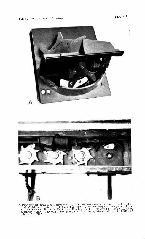
Tech. Bul. 182. U. S. Dept. oí Agriculture PLATE 8
A, DistrihutiiiK meclianLsm of distrihutor Xo. 1, a, fertilizer feed wlieel; It. gute opening; c, feed-wheel tooth; d. delivery opeuini!; e, deflector; /, baeli plate; g. fertilizer pite; h, liottom plate; i, ledge. B, Interior view of distrihutor No. 1. a, fertilizer feed wheel; b. gate opening; c, feed-wheel tooth; d, delivery o[)ening; e, deflector; /, back plate; t, fertilizer gate; ft, bottom plate; i, ledge; ;, fertilizer gate rod; fc, hopper

Tech. Bul. 182. U. S. Dept. of Agriculture
A No. I typy cf dislri 1) utor conlainin^' sainplos of 7."i, H.'i. and ;i," réspedivel.v; 11, relative quantilie:
(Irillabililv fertilizers ir(im left torielit. delivered

MECHANICAL APPWCAXIOÍT OF FEETILIZEES 49
At maximum-delivery position of the feed wheel the delivery opening is exposed sufficiently to permit the charge of fertilizer be- tween the teeth to flow freely through the opening, as shown m Figure 13, B. A large part of ü free-flowing fertilizer carried between teelh Nos. 2 and 3 immediately flows through the delivery opening. Tooth No. 1 has passed beyond the deflector, and the fertilizer being diverted from the solid part of the feed wheel is now free to flow through the delivery opening. The delivery from the ledge that occurs at this instant augments the maximum delivery but is neg- ligible in comparison with the total delivery.
The foregoing discussion dealt with the cycle of delivery produced by a feed-wheel tooth, which is very regular and distinct with free- flowing fertilizer. As the driUability score of the fertilizer becomes less, variations in delivery are introduced by the fertilizer itself in addition to those caused by the machine. Fertilizer of poor drill- ability flows in lumps rather than in finely divided particles; it bridges in the hopper, slips on the feed wheel, and supplies the feed
FIGURE 13.—I'osltions of feed wheel of distributor No. 1 at points of minimum (A) and maximum (U) delivery: a, Fertilizer feed wheel; d, delivery open-^ ing ; e, deflector ; i, ledge
wheel with only a partial charge, thus giving both uneven distribu- tion and decreased delivery.
While average percentage of deviation is a means of comparing the manner in which the fertilizers are distributed by the machine, the magnitude of the variatioH3 is more clearly shown by the maxi- mum and minimum deliveries per foot. (Table 26.)
The fertilizer of 95 driUability, which flows as freely as any fertilizer now offered on the market, was delivered with an average deviation of 23.37 per cent. The fertilizer passed through small openings in the hopper and flowed directly through the distributing mechanism when stationary, if the fertilizer gate opening was greater than that represented by notch 12, and through a much smaller opening when the machine was subjected to any motion or vibration. The fertilizer was delivered at a rate 105 pounds per acre higher than that given by the manufacturer's calibration, owing to its high apparent specific gravity and free-flowing properties. Changes of fertilizer head had a marked effect on delivery rate. Thus, with the particular type of distributor under discussion, a
98734—30—4

50 TECHNICAL BULLETIN 182, U, S. DEPT. OP AGBICULTUBB
fertilizer of 95 drillability can not be positively controlled when the fertilizer gate is more than one-third open, nor can a constant de- livery rate be maintained if great changes in fertilizer head occur.
The 85 drillability fertilizer was delivered by distributor No. 1 with an average deviation of 34.42 per cent. This material did not flow through small openings in the hopper and did not flow through the distributing mechanism when not in motion, except at a very wide gate opening. The fertilizer was delivered at a rate 180 pounds less per acre than that given on the calibration chart. Cycles of de- livery were very distinct and were the principal cause of the high average per cent deviation. The 75 fertilizer gave results very similar to those of the 85 material.
The 65 drillability fertilizer was delivered with an average de- viation of 36.95 per cent and at a reduced rate. The low rate by weight was due to a very low apparent specific gravity. It will be noted that the rate by volume exceeds that of the 75 material. The large pieces of bone, which were much heavier than the straw- like material were more numerous in certain foot intervals than in others ; this feature had some bearing on uniformity of distribution.
The 55 drillability fertilizer, while giving results somewhat sim- ilar to those of the 65 material, was delivered with an average deviation of 42.15 per cent. The delivery was more or less m bunches, because the fertilizer resisted separation to a considerable extent and did not flow freely. The fertilizer carried between the teeth of the feed wheel did not enter the delivery opening gradually, but remained intact until carried over the opening and then dropped down in a mass.
The 35 drillability material was delivered in bunches and at an exceedingly low rate. This fertilizer bridged in the hopper, slipped on the feed wheel, and worked very unsatisfactorily. In some in- stances there was no delivery of fertilizer during a 7-foot advance of the machine. The results indicate that the 35 drillability material could not be delivered under any circumstances, except at a com- paratively low rate.
The 15 drillability fertilizer bridged in the hopper and adhered in a mass to such an extent that no delivery was made.
Fortunately most of the commercial fertilizers, under favorable conditions, have physical properties similar to those of the 75 drilla- bility material. However, under unfavorable conditions their prop- erties may be similar to those of the 35 or 15 mixtures.
In Plate 9, A is shown a distributor of the No. 1 type, built espe- cially for experimental purposes. Each unit was adjusted to deliver like amounts of the same fertilizer, but in this case each compart- ment contained a 4-8-4 mixture made from different materials, in equilibrium with a relative humidity of 70 per cent. From left to right, the drillability of these mixtures, according to the scale here used, was 75, 85, and 35. The 75 drillability mixture flowed down irregularly but fairly well. The mixture in the center was a granu- lar material and flowed down steadily, while the 35 drillability mixture was damp and was delivered at a very low rate. The quantities of the three materials delivered in the same time are shown in Plate 9, B.
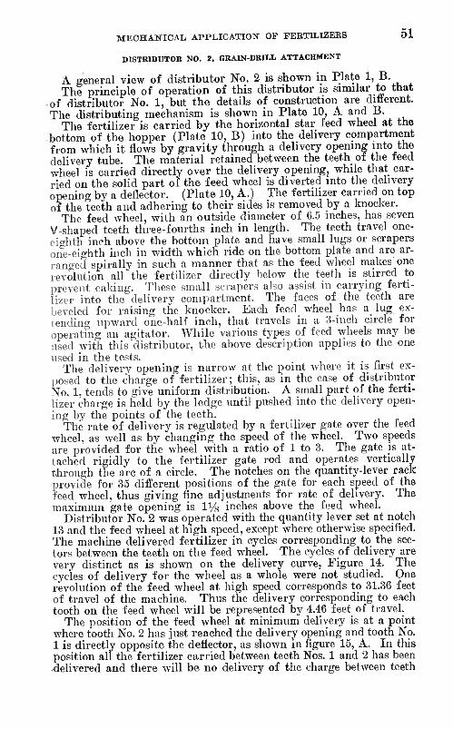
MECHANICAL APPLICATION OF FERTILIZEBS 51
DISTRIBUTOR NO. 2. GRAIN-DRILL ATTACHMENT
A general view of distributor No. 2 is shown in Plate 1, B. The principle of operation of this distributor is similar to that
of distributor No. 1, but the details of construction are different. The distributing mechanism is shown in Plate 10, A and B.
The fertilizer is carried by the horizontal star feed wheel at the .bottom of the hopper (Plate 10, B) into the delivery compartment from which it flows by gravity through a delivery opening into the delivery tube. The material retained between the teeth of the feed wheel is carried directly over the delivery opening, while that car- ried on the solid part of the feed wheel is diverted into the delivery opening by a deflector. (Plate 10, A.) The fertihzer carried on top of the teeth and adhering to their sides is removed by a knocker.
The feed wheel, with an outside diameter of 6.5 inches, has seven V-shaped teeth three-fourths inch in length. The teeth travel one- ei<^hth inch above the bottom plate and have small lugs or scrapers one-eighth inch in width which ride on the bottom plate and are ar- ran<'ed spirally in such a manner that as the feed wheel makes one revolution all the fertilizer directly below the teeth is stirred to prevent caking. These small scrapers also assist in carrying ferti- lizer into the delivery compartment. The faces of the teeth are beveled for raising the knocker. Each feed wheel has a lug ex- tending upward one-half inch, that travels in a 3-inch circle for operatfng an agitator. While various types of feed wheels may be used with this distributor, the above description applies to the one used in the tests. . .
The delivery opening is narrow at the point where it is hrst ex- posed to the charge of fertilizer ; this, as in the case of distributor No. 1, tends to give uniform distribution. A small part of the ferti- lizer charge is held by the ledge until pushed into the delivery open- ing by the points of the teeth.
The rate of delivery is regulated by a fertilizer gate over the feed wheel, as well as by changing the speed of the wheel. Two speeds are provided for the wheel with a ratio of 1 to 3. The gate is at- tached rigidly to the fertilizer gate rod and operates vertically through the arc of a circle. The notches on the quantity-lever rack provide for 35 different positions of the gate for each speed of the feed wheel, thus giving fine adjustments for rate of delivery. The maximum gate opening is li/s inches above the feed wheel.
Distributor No. 2 was operated with the quantity lever set at notch 13 and the feed wheel at high speed, except where otherwise specified. The machine delivered fertilizer in cycles corresponding to the sec- tors between the teeth on the feed wheel. The cycles of delivery are very distinct as is shown on the delivery curve, Figure 14. The cycles of delivery for the wheel as a whole were not studied. One revolution of the feed wheel at high speed corresponds to 31.36 feet of travel of the machine. Thus the delivery corresponding to each tooth on the feed wheel will be represented by 4.46 feet of travel.
The position of the feed wheel at minimum delivery is at a point where tooth No. 2 has just reached the delivery opening and tooth No. 1 is directly opposite the deflector, as shown in figure 15, A. In this position all the fertilizer carried between teeth Nos. 1 and 2 has been -delivered and there will be no delivery of the charge between teeth

52 TECHNICAL BULLETIN 18 2, U. S. DEPT. OF AGRICULTURE
2 and 3 until tooth No. 2 has advanced far enough to expose the de- livery opening to the charge of fertilizer. Also, tooth No. 1, being directly in the path of fertilizer diverted by the deflector, tends to. retard the flow, which contributes to minimum delivery at the instant in question. The delivery of fertilizer from the top of the teeth by the knocker, as well as the delivery from the ledge by the points of the teeth, occur at the instant of minimum delivery, and thus the tendency is to prevent an extremely low point in the cycle of delivery ; however, the combined effect is very slight in most cases.
The ]iosition of the feed wheel for maximum delivery (fig. 15, B) is obvious from the preceding discussion.
The cycle of delivery corresponding to each tooth is evident throughout the series of tests, but becomes less distinct with fer- tilizers of poor drillability. In distributing such a fertilizer, the irregularities due to its own inherent properties may be much greater than those due to the distributing mechanism. Fertilizers havirig poor drillability also have decreased delivery rates, as explained in the discussion of distributor No. 1. Fertilizers having very poor drillability are not delivered at all.
¿a
10
0 ̂ ^ \ . . y \ y ̂ ^
5 1 0 1 s ¿u Distance In feet
FIGURE 14.—Delivery curve of distributor No. 2
The 95 drillability fertilizer flowed by gravity through the dis- tributing mechanism of distributor No. 2 when stationary at a gate opening corresponding to notch 16. Increased head and any motion or vibration of the machine ( aused the fertilizer to flow by gravity through a smaller gate opening. Because of the method of operating the gate, that part of the gate slot above the gate is not entirely closed except when the gate is in its extreme upward position. When the height of the fertilizer in the hofiper reached the top of the gate slot, the 95 fertilizer flowed out freely over the to]) of the gate, al- though the other fertilizers did not. Thus, if positive control is to be maintained, this fertilizer can not extend above tlie gate slot, nor can the gate be opened wider than notch 16. The ieililizer was de- livered with an average deviation of 88.38 per cent. The cycles of delivery for each feed-wheel tooth were very distinct and were of considerable amplitude.
The 85 drillability material was delivered at a rate one-half that of the 95 fertilizer, by weight, but with about the same degree of uniformity; the difference by volume was only about 11 i)er cent. This material did not flow through the opening immediately above the fertilizer gate, nor through the gate opening proper by gravity,, except at an extremely wide opening. Cycles of delivery for the- teeth on the feed wheel were very regular and distinct.

Tech. Bul. 182. U. S. Dept. of Agriculture PLATE 10
A, Distributing mechanism of distributor No. 2, a, fertilizer feed wheel; b, gate opening; c, feed-wheel tooth; d, delivery opening; e, deflector;/, back plate; h, bottom plate; i, ledge; /, agitator drive lug: n, scraper. B, Interior view of distributor No. 2, a, fertilizer feed wheel; b, gate opening; c, feed-wheel tooth; d, delivery opening; e, deflector;/, back plate; g, fertilizer gate; h, bottom plate;,?', fertilizer gate rod; k, hopper; /, agitator drive lug; m, knocker; n, scraper; o, opening above fertilizer gate. C, Delivery of powdered urea having a drillability of 3^, by distributor No. 2

Tech. Bul. 182. U. S. Dept. of Agriculture
A, DistribiitiriR mechanism of disfrihutor Xo 3. a, fertilizer feed i)late; h, ferlilizer plow; c, feed- plate wall; d, feed-plate shield; e. shield teeth, f. feed-plate cleaner; g, feed-i)late IUKS; A, hopper; !. fertilizer divider;;, deli\er> tube. I!, Distnlnitingmechanismof di.stributor No. 4, o, fertihzer feefl wheel; b, feed-wheel padille, c, feed-w heel shield; d, delivery oiieiiiiii:: e, deliver.v tube; /, fer- tilizer gate; g, gate opening, /i, hopper, i, agitator;;, feed wheel and agitator shaft '
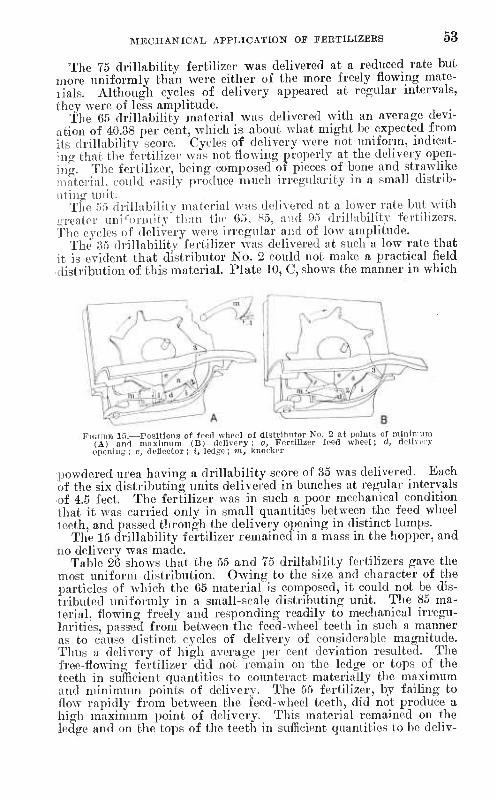
MECHANICAL APPLICATION OF FERTILIZERS 53
The 75 drillability fertilizer was delivered at a reduced rate but more uniformly than were either of the more freely flowing mate- rials. Although cycles of delivery appeared at regular intervals, they were of less amplitude.
the G5 drillability material was delivered with an average devi- ation of 40.38 per cent, which is about what might be expected from its drillability score. Cycles of delivery were not uniform, indicat- ing that tlie fertilizer was not flowing properly at the delivery open- ing. The fertilizer, being composed of pieces of bone and strawlike material, could easily ]n-oduce much irregularity in a small distrib- uting unit.
The 55 drillabilitv material was delivered at a lower rate but with i;Teater uni'orniity'than tlic 65. S5, and 95 di'illnbility fertilizers. The cycles of delivery were irregular and of low amplitude.
The 35 drillability fertilizer was delivered at such a low rate that it is evident that distributor No. 2 could not make a practical field distribution of this inaterial. Plate 10, C, shows the manner in which
FiGUBB 15.—Positions of feed wheel of distributor No. 2 at points of mlnitrnm (A) aud maximum (B) delivery: a. Fertilizer feed wheel; d, delivery opeuiug ; c, deflector ; i, ledge ; m, knocker
powdered urea having a drillability score of 35 was delivered. Each of the six distributing units delivered in bunches at regular intervals of 4.5 feet. The fertilizer was in such a poor mechanical condition that it was carried only in small quantities between the feed wheel teeth, and passed through the delivery opening in distinct lumps.
The 15 drillability fertilizer remained in a mass in the hopper, and no delivery was made.
Table 26 shows that the 55 and 75 drillability fertilizers gave the most uniform distribution. Owing to the size and character of the particles of which the 65 material is composed, it could not be dis- tributed uniformly in a small-scale distributing unit. The 85 ma- terial, flowing freely and responding readily to mechanical irregu- larities, passed from between the feed-wheel teeth in such a manner as to cause distinct cycles of delivery of considerable magnitude. Thus a delivery of high average per cent deviation resulted. The free-flowing fertilizer did not remain on the ledge or tops of the teeth in sufficient quantities to counteract materially the maximum and minimum points of delivery. The 55 fertilizer, by failing to flow rapidly from between the feed-wheel teeth, did not produce a high maximum point of delivery. This material remained on the ledge and on the tops of the teeth in sufficient quantities to bo deliv-

54 TECHNICAL BULLETIN 18 2, U. S. DEPT. OF AGEICULTUEE
ered at the point of minimum delivery, so that the amplitude of the cycle was not great. In addition, the scrapers on the bottom of the teeth delivered fertilizer at the point of minimum delivery, and no doubt in greater relative amounts with a medium than with a high- drillability material. The mechanism seems to be so designed that cycles of delivery are less marked with a 55 drillability than with an 85 drillability fertilizer.
DISTRIBUTOR NO. 3, POTATO-PLANTER ATTACHMENT
Distributor No. 3, shown in Plate 2, A, is of the revolving-plate type. It is also illustrated in Plate 11, A, with the hopper raised to show the internal construction.
The feed plate carries the fertilizer to the plow, which diverts it over the wall of the feed plate into the delivery tubes. The flow of fertilizer is divided and flows through two delivery tubes instead of one ; thus fertilizer is distributed on both sides of the row.
The fertilizer is fed to the shielded part of the feed plate through a 11/4-inch fixed ojiening designated as the throat opening. The feed plate is 161/2 inches in diameter and has a wall 1% inches high. The central portion has radial rows of lugs or small projections which assist in carrying the lower layer of fertilizer with the plate and cause it to move outward toward the periphery of the plate. V-shaped teeth, set 1 inch on centers, extend downward three-fourths inch into the throat opening and at a distance of 2% inches from the periphery of the feed plate. As the fertilizer in the hopper moves along the teeth, it is forced outward by the deflecting action of the teeth.
A cleaner rides on the feed plate to insure that the throat opening is free from obstructions which might be caused by fertilizer ad- hering or caking on the feed plate. The rate of delivery is reg- ulated by the depth at which the plow is set and the speed of the feed plate. There is no scale to indicate the position of the plow, which for the tests was set five-eighths inch above the feed plate. For convenience an indicator was attached to the plow, and grad- uations were stamped on the hopper.
Uneven distribution with free-flowing fertilizer was caused mainly by variations in the relative height of the feed-plate wall at the plow. A maximum variation of three-sixteenths inch was found as the plate made one revolution, the variation being caused by the fact tliat the plate was not at right angle to its axis. One revolu- tion of the feed plate corresponded to 15.2 feet travel of the machine. Thus a distinct cycle of delivery is shown, even in a 20-foot test, by a gradual increase and decrease in the delivery rate. (See deliv- ery curve. Figure 16), Minor deviations within the cycle of delivery were caused by small irregularities in the feed-plate wall, and the jerky motion of the plate.
The 95 drillability fertilizer, although flowing very freely and uniformly, was subject to a relatively high average per cent devia- tion in delivery due to the mechanical imperfections of the dis- tributing mechanism. The fertilizer was distributed under a 1-inch head, which was sufficient to raise the fertilizer outside the throat opening to the top of the plate wall. It is evident that an ap-

MECHANICAL APPLICATION OF FEBTILIZEBS 55
preciable increase in head would cause the fertihzer to nse to a point where it would flow over the plate wall. A decrease in deliv- ery rate was shown at the end of the test, due to a reduction of
The 85 and 75 drillability fertilizers were distributed with about the same degree of uniformity as the 95 fertilizer. The high rate of delivery by a large type of distributor makes possible the same degree of uniformity of distribution in each case, notwithstanding minor differences in the drillabilities of the materais.
The 65 drillabihty mixture was agitated and broken up as it passed between the teeth in the throat opening and as a result was dis- tributed with a fair degree of uniformity. At any particular ad- justment of distributor No. 3 the quantity delivered depends mainly upon the effect of head or lateral pressure at the throat opening in forcing the fertilizer to the outer part of the feed plate. Since the 65 drillability mixture is a light material, and its physical properties are such that the mixture does not respond readily to pressure, it was not forced to the outer part of the feed plate at as
Distance in ffiet
FIGURE 16.—Delivery curve of distributor No. 3
great a depth as were the fertilizers of higher drillability, and as a result was delivered at a reduced rate.
The 55 drillability fertilizer wa.s delivered at a low rate, espe- cially as compared with the 85 drillability fertilizer,'which is the same material in granular form, for reasons similar to those stated concerning the 65 drillability fertilizer. The 55 drillability material was subject to uneven distribution. It was finely divided as it passed between the teeth in the throat opening, but because of the fineness of the particles and their disposition to adhere when the fertilizer piled up at the plow to flow over the plate wall by gravity, it flowed in lumps. A free-flowing material flows over the plate wall at the plow in a continuous stream several inches wide, while a material such as the 55 drillability fertilizer slides off in lumps. It is this characteristic which accounts for the greater unevenness of distribution of the latter.
The distribution of the 35 drillability mixture was similar to that of the 55 drillability material, although it was subject to greater variations in delivery caused by the fertilizer piling up higher at the plow and flowing over the plate wall in larger lumps. The un- expected high rate of delivery as compared to that of the 55 drilla-

56 TECHNICAL BXJLLETIIT 18 2, TJ. S. DEPT. OF AGEICULTUEB
bility fertilizer may be accounted for as follows : The latter, being finely powdered, passed beyond the hopper teeth in a compact form and tapered oif in depth toward the periphery of the feed plate, while the 35 drillability mixture was given a loose texture by the teeth and was carried at a greater and more uniform depth. Since the plow was set some distance above the feed plate, the upper part of the charge of fertilizer determined the delivery rate. It is possiJDle that a greater weight of the 55 drillability fertilizer was carried on the shielded part of the plate, but if a large percentage of it passed under the plow the delivery rate would necessarily be small.
The 15 drillability mixture gave a very small delivery through the distributing mechanism. This fertibzer'had a tendency to remain in a mass in the hopper. The small amount that passed out of the hopper piled up at the plow and broke off in lumps so large that they would not enter the delivery tubes.
DISTRIBUTOR NO. 4, POTATO-PLANTER ATTACHMENT
Distributor No. 4 is an implement of the paddle-wheel type and is used as an attachment on a potato planter. (PL 2, B.) The principle of operation is shown in Plate 11, B.
The fertilizer enters the feed-wheel chamber from either side through the gate opening and is carried by the paddles on the feed wheel to the delivery opening where it flows into the delivery tube. Both gravity and centrifugal force cause the fertilizer to leave the paddle at the delivery opening. The rate of delivery is controlled by the fertilizer gate in the feed-wheel chamber. The gate opening can not be entirely closed. The rate of delivery may also be varied by changing the speed of the feed wheel, which can be done only by «hanging the size of sprockets. The distributor is rated for 250 pounds per acre at the minimum gate opening of 0.5 inch and 3,500 pounds per acre at the maximum gate opening of 2 inches. It was operated at the manufacturer's rating of 1,000 pounds per acre. A scale indicates the position of the fertilizer gate and the manufac- turer's rating.
The feed wheel, which is 8 inches in diameter, has eight paddles approximately 1^/^ inches wide and 2 inches long. The feed-wheel shaft has on each side of the feed-wheel chamber three projecting fingers to form an agitator. The bottom of the hopper slopes toward the gate openings which, with the action of the agitator, facilitates tlie flow of fertilizer into the feed-wheel chamber. An agitator is also provided in the hopper above the feed-wheel shield to prevent caking or bridging at that point.
The feed wheel makes one revolution as the machine travels through a distance of 11.13 feet. The delivery of each paddle corresponds to 1.39 feet travel of the machine. The feed wheel as a whole produced a cycle of delivery as shown on the delivery curve. (Fig. 17.) The paddies also produced cycles or impulses of delivery. The paddle cycles can not distinctly appear on the delivery curve, since the length of cycle is just a little greater than the intervals of delivery recorded. However, with certain fertilizers, especially when the delivery rate was low, the paddle cycles were apparent to the eye.

MECHANICAL APPLICATION OF FEETILIZEES 57
The following are causes of uneven distribution with machine No. 4- The principle of operation, which causes a delivery of tertUizer at intervals of 1.39 feet; mechanical irregularities in the distributor mechanism; and irregular flow of fertilizer into the feed-wheel chamber. The paddles on the feed wheel vary one-eighth inch in length and are not uniform in shape, both of which factors tend to vary the amount of fertilizer the different paddles will carry Ihese variations are particularly noticeable at a minimum rate ot delivery. Fertilizer of suitable drillability flows through the gate opening at a uniform rate, but as the drillability becomes poorer the flow be- (•omos more irregular. . j. ., j i-
The 95 drillability fertilizer flowed by gravity out ot the delivery opening, with the distributing mechanism stationary and the gate closed as far as possible ; for that reason the fertilizer was not under control, and no results were recorded.
40
/ \ ^ / \ / >-.,
V / / "^ 7*
\ / \ / / \ /
/ \, -^
30
1 ■\ / \ / \ /
/
Í 1
0 1 s 0 1 5 20
Distance in feet
FiGURJä 17.—Delivery curve of distributor No. 4
The 85 drillability material flowed freely and uniformly into the feed chamber and was distributed with a low average percentage deviation. It is true with distributor No. 4—as perhaps with some others—that the distributing mechanism was designed to function most eíBciently at a medium or high-delivery rate. When distrib- utor No. 4 is delivering at a low rate, small quantities of fertilizer are carried at the tips of the paddles and delivered in distinct im- pulses, while at a high rate the fertilizer must necessarily be carried on the entire paddle surface, and at the point of dehvery some time is required for all the fertilizer to leave the paddle. The latter condition contributes greatly to uniform distribution.
The 75 drillability material was delivered less uniformly and at a rate about one-half that of the 85 drillability mixture. The dis- tributor depends to a great extent on flow by gravity through the gate opening, thus a decided reduction in delivery rate will be found with fertilizers that do not flow freely.
The 65 drillability fertilizer was delivered at a higher rate than the 75 drillability material, resulting in more uniform distribution. The fertilizer is of such a nature that continual stirring by the
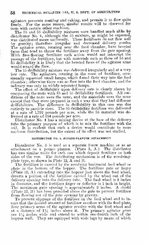
68 TECHNICAL. BULLETIfT 182, U. S. DEFT. OF AGRICULTURE
agitators prevents matting and caking, and permits it to flow quite freely. For the same reason, similar results will be observed for tests with certain other machines.
The 55 and 35 drillability mixtures were handled much alike by distributor No. 4, although the 55 mixture, as might be expected, was distributed more uniformly. These fertilizers do not flow well by gravity; therefore irregular and decreased delivery results. The agitator arms, rotating near the feed chamber, have beveled faces that tend to throw the fertilizer away from the gate opening. With free-flowing fertilizer such action would not interrupt the passage of the fertilizer, but with materials such as those of 55 and 35 drillability it is likely that the beveled faces of the agitator arms would retard the flow.
The 15 drillability mixture was delivered irregularly and at a very low rate. The agitators, rotating in the mass of fertilizer, occa- sionally separated small lumps, which found their way into the feed chamber ; otherwise there was no flow into the feed chamber, and the delivery was only in widely separated lumps.
The effect of drillability upon delivery rate is clearly shown by comparing the tests with 85 and 55 drillability fertilizers. All con- ditions of the tests were the same, and the materials were the same except that they were prepared in such a way that they had different drillabilities. The difference in drillability in this case was due entirely to particle sizes. The 85 drillability fertilizer was delivered at a rate of 1,722 pounds per acre, while the 55 material was de- livered at a rate of 254 pounds per acre.
Distributor No. 4 has a mixing device at the base of the delivery tube the primary purpose of which is to mix the fertilizer with the soil. It is evident that such a device would contribute to more uniform distribution, but the extent of its effect was not studied.
DISTRIBUTOR NO. 5, POTATO-PLANTER ATTACHMENT
Distributor No. 5 is used as a separate 2-row machine or as an attachment on a potato planter. (Plate 3, A.) The distributor has two similar units for each row which deposit fertilizer on both sides of the row. The distributing mechanism is of the revolving- plate type, as shown in Plate 12, A and B.
The fertilizer is carried by the revolving horizontal feed wheel or plate in the bottom of the hopper. The fertilizer gate or finger (Plate 12, A) extending into the hopper just above the feed wheel, diverts a portion of the fertilizer carried by the wheel out of the delivery opening into the delivery tube. The feed wheel is 9 inches in diameter, and the fertilizer finger or deflector is 1 inch in height. The maximum gate opening is approximately 2 inches. A shield (Plate 12, B) has been provided above the gate to prevent fertilizer from flowing out of the gate opening by gravity.
To prevent slippage of the fertilizer on the feed wheel and to in- sure that the desired amount of fertilizer revolves with the feed plate, four primary arms of the agitator revolve with the feed wheel and at a distance of 1% inches above it. The primary agitator arms are li^ inches wide and extend to within one-fourth inch of the hopper wall. They are equipped with wide lugs by means of which

Tech. Bul. 182. U. S. Dept. of Agriculture PLATE 12
S.GC
■S ML;;
.£■8
s^-S
Si"
ó 3'
.^Hä"'
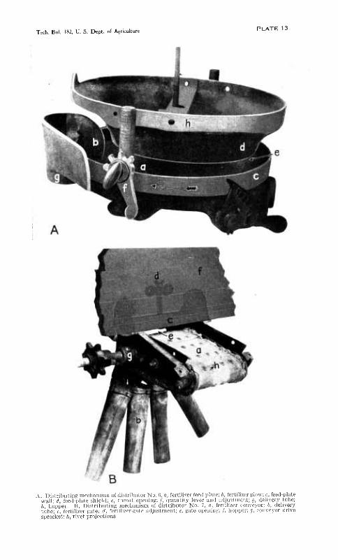
Tech. Bul. 182, U. S. Dept. of Agriculture PLATE 13
A, Distribiilinti mechanism of ílislrilüilor No. 0, a, fertilizer feed plate; b, fertilizer plow; c, feed-plate wall; d, feed-plate shield; e, throat opeidriB;/, (luautity lever and adjustment; g, delivery tube; ft, hopi)er. li, Dislribiitint; mechanism of distributor No. 7, n, fertilizer conveyor; b, delivery tube; c, fertilizer i;ali'; d. fertilizer-gate adjustment; e, gate opening; /, hojiper; g, conveyor drive sprocket: ft, rivet projections

MECHANICAL APPLICATION OF FEETILIZEES 59
they are driven and which assist in carrying the fertilizer with the feed wheel. In revolvinji, the primary agitator arms pass between the fertilizer gate and the gate shield. Secondary agitator arins prevent bridging and caking of the fertilizer at higher points in the hopper.
The rate of delivery is regulated by the position of the fertilizer gate or amount of gate opening. The delivery could also be varied by changing the speed of the feed wheel. For the tests tlie fertilizer gate was set approximately one-third open. A graduated quantity lever rack indicates the position of the fertilizer gate.
It is presumed that a cycle of delivery of only slight amplitude exists for the feed wheel proper. On the delivery curve (Fig. 18) points of minimum delivery appear wliich correspond to tlie primary agitator arms. Since the feed wheel makes one revolution during 15.3 feet of travel of the machine, a primary agitator arm passes ihe gate opening at intervals of 3.83 feet.
The 85 drillability fertilizer flowed to some extent by gravity tlirough the gate opening with the distributing mechanism station-
■¿0
^ -^ ^^ ^
1 y \ y N ^
y
-»
0 1 0 ( 5 20
FIGURP: 18.-
Distance in feet
-Delivery curve of distributor No. 5
ary except when a primary agitator arm was in the position of just reacliing the gate shield. Evidently when the wide agitator arm was in this position tlie gate opening was sufficiently protected to prevent the gravity flow of the fertilizer. In other words, most of the pressure due to the head of the fertilizer was carried by the gate shield and the agitator arm. This fertilizer gave very uniform distribution, but showed points of low dolivei-y at regular intervals, corresponding to the moments of no-gravity flow. The existence, then, of points of low delivery was due to the absence of head on the fertilizer being delivered.
The 15 drillability fertilizer was delivered at a low rate and in largo lumps. Flow out of the delivery opening occurred only when a primary agitator arm was passing the opening. The fertilizer was subjected to sufficient pressure, as it was being delivered, to cause moisture to appear on the surface. It passed through the delivery opening in a column that broke down only in largo lumps to enter the delivery tube. In some of the tests the lumps were so large that they would not enter the delivery tube. In the distribu- tion of fertilizer of 15 drillability, the delivery as affected by the primary agitator ai-ms was directly the reverse of that in the case of the 85 drillability fertilizer; that is, the points of maximum deliv- ery occurred at the time the agitator arms passed the gate opening.

60 TECHNICAL BULLETIN 18 2, U. S. DEPT. OF AGEICULTUEE
The agitator arms as they passed the gate opening in this case reduced the slippage of the fertilizer on the feed plate.
The 35 drillability mixture was delivered at a reduced rate and with à high average per cent deviation. The action of the fertilizer was similar to that of the 15 drillability mixture, except that con- ditions were not so extreme. A noticeable impulse of delivery was present, which indicated that less slippage on the feed plate occurred as the primary agitator arms passed the delivery opening. The column of fertilizer in passing out of the delivery opening tended to remain intact, and as a result broke off in lumps to enter the delivery tube.
The 55 drillability fertilizer gave results which may be considered to be about midway between those of the two extremes just discussed. While slippage of the fertilizer on the feed wheel was not so evident as in the case of the 35 drillability mixture, from the character of the material it is reasonable to suppose that it would resist move- ment in the hopper and at the gate opening. It is probable that the low rate of delivery as shown in the results was due partially to the absence of fertilizer in the spaces immediately below the wide agitator arms. The fertilizer did not flow uniformly into the delivery tube as did the 85 fertilizer, but broke into lumps at the delivery opening.
The 75 and 65 drillability fertilizers were distributed very uni- formly. They were delivered, however, at a lower rate than the 85 drillability material, evidently due to slippage on the feed wheel.
DISTRIBUTOR NO. 6, CORN-PLANTER ATTACHMENT
Fertilizer distributor No. 6 (pi. 3, B) is of the levolving-plate typo. The horizontal feed plate revolves and carries the fcM'tilizer to the plow, which diverts it over the wall of the plate into the delivery tube. (PI. 13, A.)
The rate of delivery is varied by changing the height of the feed- plate shield above the feed plate; this regulates the depth of fer- tilizer carried to the plow. Delivery rate is also controlled by the speed of the feed plate. Three speeds are provided. The plow is 1 inch wide and nonadjustable. Minute adjustment of the throat opening is possible, but there is no scale to indicate the jiosition of the plate shield. For convenience in testing, the hopper-adjusting device was graduated to show the exact relative positions.
Fertilizer is continuously supplied to the shielded part of the feed plate by virtue of the location and peculiar shape of the shield, the edge of which is spirally shaped. That part of the shield back of the plow is placed near the feed-plate Avall, an arrangement which per- mits the uncharged part of the plate to pass directly under the charge of fertilizer in the hopper. In the direction of plate move- ment the shield edge gradually recedes from the plate wall, to clear the inner edge of the plow, at which point it abruptly extends out- ward to the point back of tlie plow before mentioned. The action of the shield in regulating the quantity of fertilizer carried to the plow is similar to that of a straight gate, except that the band of fer- tilizer is gradually widened throughout the revolution of the feed plate.
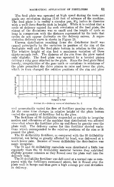
MECHANICAL APPLICATION OF FEETILIZEES 61
The feed plate was operated at high speed during the tests and made one revolution during 17.45 feet of advance of the machine. The feed plate is in reality a circular pan, 9Vi inches in diameter with a wall three-fourths inch in height. While it is evident that a cycle of delivery existed for each revolution of the feed plate, the extent of the deviations was so small and the length of cycle so long in comparison with the distance represented by the tests that cycles do not appear distinctly on the delivery curves. A repre- sentative delivery curve is shown in Figure 19.
Uneven distribution resulting frdm the distributor itself was caused principally by the variation in position of the rim of the feed-plate wall and the feed-plat€ bottom in relation to the plow. The relative height of rim had a maximum variation of three thirty-seconds inch. The distance of the rim from the plow varied only slightly. The feed plate was operated by a beveled pinion driving a ring gear attached to the plate. Since the feed plate fitted loosely, irregularities of the gear teeth or variations in resistance of the plate permitted the drive pinion to raise and lower the plate, which in turn changed the relative positions of the rim and plow
FIGURE 19.-
Distance în feet
-Delivery curve of distributor No. 6
and momentarily varied the flow of fertilizer passing over the rim. At the same time changes in relative height of the plate bottom varied the quantity of fertilizer fed to the plow.
The fertilizer of 95 drillability responded so quickly to irregular motion and vibrations of the machine that distribution was affected iomcwhat where the fertilizer piles up and flows by gravity over the plate wall. The delivery curves for this fertilizer showed varia- tions which corresponded to the relative positions of the rim as it I^assed the plow.
The 85 drillability fertilizer, as compared with the 95 drillability material, not being so greatly affected by head, was delivered at a much lower rate. Because of lower drillability the distribution was more irregular.
The 75 and 65 drillability materials were distributed a little less regularly than the 85 drillability material because they exhibited slightly greater cohesion as they flowed over the plate wall into the delivery tube.
The 55 drillability fertilizer was delivered at a normal rate as com- pared with the fertilizers mentioned above, but it flowed over the plate wall in lumps and thus gave a high average per cent deviation in delivery.

62 TECHNICAL BULLETIN 18 2, TJ. S. DEPT. OP AGRICULTURE
The 35 drillability mixture resisted separation to such an extent that slippage on the feed wheel was high, and only a small quantity of iertilizer was carried through the throat opening. The almost negligible amount of delivery was made in lumps, with no delivery most of the time. As a consequence the average per cent deviation was exceptionally high.
The 15 drillability mixture remained in a mass within the hopper, and no delivery was made.
DISTRIBUTOR NO. 7, BROADCAST OR 3-ROW DISTRIBUTOR
This machine, shown in Plate 4, A, is of the belt-conveyor type and is essentially a broadcasting machine, although the fertilizer may be delivered in bands about 8 inches wide. The distributor has three units rigidly fixed at 2.75 feet apart. One of the units is illustrated in Plate 13, B.
The fertilizer is carried by an endless canvas conveyor 6 inches in width to a point outside the hopper, where it falls by gravity into the delivery tubes. Chains running over sprockets are fastened to both edges of the belt to prevent slippage and creeping. Each unit is equipped with four delivery tubes which are adjustable for broad- casting the fertilizer. Since the machine has no furrow openers, the fertilizer must be broadcast on the ground surface or distributed in open furrows.
The rate of delivery is controlled by the fertilizer gate 5 inches in width, which determines the depth of fertilizer carried on the conveyor. It would be possible to vary the delivery by changing the speed of the conveyor, but no such provision is made on this distributor. The gate is adjusted by a thumbscrew, but there is no scale to indicate the position of the gate. The maximum gate opening is 1 inch, and the gate was set approximately one-fourth open for the tests.
Uneven distribution of free-flowing fertilizer is caused mainly by the irregularities in the surface of the conveyor. Metal strips at intervals of 2 inches connect the chains at either side of the belt and act as supports and reenforcements for the canvas. The canvas is riveted to the metal strips ; thus a row of rivet ends projects at each support. Moreover, the ends of the canvas are lapped, which feature gives another irregularity in the belt surface.
A cycle of delivery occurs for each revolution of the convej'or, which represents 15.i feet of travel of the machine. Variations in delivery occur at regular intervals corresponding to the canvas supports or rows of j^rojecting rivets; these were clearly visible to the eye in certain tests. The variations corresponding to the rows of rivets occurred at intervals of 16.5 inches of travel of the machine and for that reason can not appear regularly on tlie delivery curve. (Fig. 20.) However, points of maximum or mininuun delivery may be indicated on the delivery curve when either of them falls near the center of a 1-foot interval measured during the tests.
Since the 95 drillability fertilizer flowed out of the hopper by gravity, both through the gate opening and at the point where the conveyor entered, no results were recorded.
The 85 drillability fertilizer was distributed quite uniformly. The principal variations in the normal flow were points of decreased
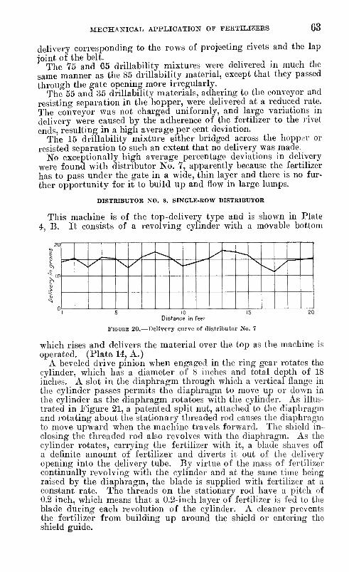
MECHANICAL APPLICATION OP FBBTILIZEES 63
delivery corresponding to the rows of projecting rivets and the lap joint of the belt.
The 75 and 65 drillability mixtures were delivered in much the same manner as the 85 drillability material, except that they passed through the gate opening more irregularly.
The 55 and 35 drillability materials, adhering to the conveyor and resisting separation in the hopper, were dehvered at a reduced rate. The conveyor was not charged uniformly, and large variations in delivery were caused by the adherence of the fertilizer to the rivet ends, resulting in a high average per cent deviation.
The 15 drillability mixture either bridged across the hopper or resisted separation to such an extent that no delivery was made.
No exceptionally higli average percentage deviations in delivery were found with distributor No. 7, apparently because the fertilizer has to pass under the gate in a wide, thin layer and there is no fur- ther opportunity for it to build up and flow in large lumps.
DISTRIBUTOR NO. 8, SINGLE-ROW DISTRIBUTOR
This machine is of the top-delivery typo and is shown in Plate 4, B. It consists of a revolving cylinder with a movable bottom
I I IS 10 15 2Q
Distance in feet
FIGURE 20.—Delivery curve of distributor No. 7
which rises and delivers the material over the top as the machine is operated. (Plate 14, A.)
A beveled drive pinion when engaged in the ring gear rotates the cylinder, which has a diameter of b inches and total depth of 18 inches. A slot in the diaphragm through which a vertical flange in the cylinder passes permits the diaphragm to move up or down in the cylinder as the diaphragm rotatoes with the cylinder. As illus- trated in Figure 21, a patented split nut, attached to the diaphragm and rotating about the stationary threaded rod causes the diaphragm to move upward when the machine travels forward. The shield in- closing the threaded rod also revolves with the diaphragm. As the cylinder rotates, carrying the fertilizer with it, a blade shaves off a definite amount of fertilizer and diverts it out of the delivery opening into the delivery tube. By virtue of the mass of fertilizer continually revolving with the cylinder and at the same time being raised by the diaphragm, the blade is supplied with fertilizer at a constant rate. The threads on the stationary rod have a pitch of 0.2 inch, which means that a 0.2-inch layer of fertilizer is fed to the blade during each revolution of the cylinder. A cleaner prevents the fertilizer from building up around the shield or entering the shield guide.
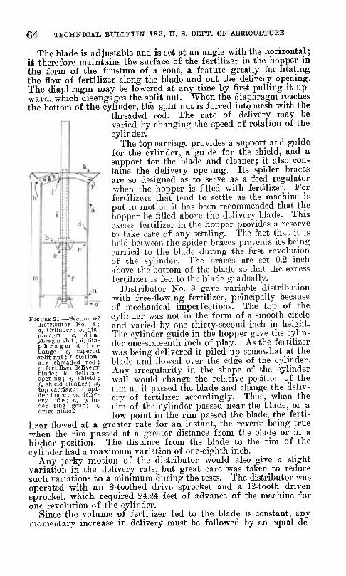
64 TECHNICAL BULLETIN 18 2, IT. S. DEPT. OF AGRICULTURE
The blade is adjustable and is set at an angle with the horizontal ; it therefore maintains the surface of the fertilizer in the hopper in the form of the frustum of a cone, a feature greatly facilitating the flow of fertilizer along the blade and out the deliverj; opening. The diaphragm may be lowered at any time by first pulling it up- ward, which disengages the split nut. When the diaphragm reaches the bottom of the cyhnder, the split nut is forced into mesh with the
threaded rod. The rate of delivery may be varied by changing the speed of rotation of the cylinder.
The top carriage provides a support and guide for the cylinder, a guide for the shield, and a support for the blade and cleaner; it also con- tains the delivery opening. Its spider braces are so designed as to serve as a feed regulator when the hopper is filled with fertilizer. For fertilizers that tend to settle as the machine is put in motion it has been recommended that the hopper be filled above the delivery blade. This excess fertilizer in the hopper provides a reserve to take care of any settling. The fact that it is held between the spider braces prevents its being carried to the blade during the first revolution of the cylinder. The braces are set 0.2 inch above the bottom of the blade so that the excess fertilizer is fed to the blade gradually.
Distributor No. 8 gave variable distribution with free-flowing fertilizer, principally because of mechanical imperfections. The top of the cylinder was not in the form of a smooth circle and varied by one thirty-second inch in height. The cylinder guide in the hopper gave the cylin- der one-sixteenth inch of play. As the fertilizer was being delivered it piled up somewhat at the blade and flowed over the edge of the cylinder. Any irregularity in the shape of the cylinder wall would change the relative position of the rim as it passed the blade and change the deliv- ery of fertilizer accordingly. Thus, when the rim of the cylinder passed near the blade, or a low point in the rim passed the blade, the ferti-
lizer flowed at a greater rate for an instant, the reverse being true when the rim passed at a greater distance from the blade or in a higher position. The distance from the blade to the rim of the cylinder had a maximum variation of one-eighth inch.
Any jerky motion of the distributor would also give a slight variation in the deliverj^ rate, but great care was taken to reduce such variations to a minimum during the tests. The distributor was operated with an 8-toothed drive sprocket and a 12-tooth driven sprocket, which required 24.24 feet of advance of the machine for one revolution of the cylinder.
Since the volume of fertilizer fed to the blade is constant, any momentary increase in delivery must be followed by an equal de-
FIOUEB 21.—-Section of distributor No. S ; a. Cylinder ; b, dia- phragm ; Cj d i a- phragm slot ; d, dia- pliragm drive flange ; e, tapered split nut ; /, station- ary threaded rod ; g, fertilizer delivery blade ; h, delivery opening ; i, shield ; i, shield cleaner ; k, top carriage ; Ï, spi- der trace ; m, deliv- ery tube ; n, cylin- der ring gear ; o, drive pinion

Tech. Bul. 182. U. S. Dept. of Agriculture
A, Distributing mechanism ot distributor Ko. 8, a, cylinder; b. diaphraRni; c, diiipliraütn slot; d (iiarihrasm drive flange; g, fertilizer delivery blade; ft, delivery opening; i, shield; j, shield cleaner; k, top carriaüe; /, spider brace; m. delivery tube, il, Distribution of ])olassium ndrate tiy distributor No. 8, a, crystalline; b, pellet ; c, powdered

Tech. Bui. 182. U. S. Dept. of Agricultui PLATE 15
A, Distributing mechanism of distributor Xo. 9. a, fertilizer feed piale; h, Iiopper; c, throat opening; d, tappet Hange; e, tapitel-flange lug; f, tappet; tj, tappet rod; li. tappet .spring; /. feed-plate stop arm; j, adjustable plate stop: k, quantity lever and rack; /, jilate adjustment; m, land wheel. B, Distribution of 95 drillahihty fertilizer by distributor Xo. "J

MEOHANIOAIi APPLICATION OF FEETILIZEKS 66
crease in delivery, and vice versa. No distinct cycle of delivery was apparent in the delivery curve, of which Figure 22 shows a repre- sentative portion. All variations are comparatively small, and the variations occur irregularly because they are largely due to the minor changes in relative positions of a loose-fitting cylinder.
The fertilizers of low drillability gave greater variations in deliv- ery because of their irregular flow from the blade over the rim of the cvlinder.
The 95 drillability material flowed so freely that it responded very quickly to movements or vibrations of the machine, both at the point of delivery and on the sloping surface of the fertilizer in the cylinder.
Table 26 shows that delivery rate by volume was the same for all materials except the 95 drillability fertilizer. The probable causes of a slightly higher rate with the latter material were (1) slight leakage past the diaphragm, and (2) loss from the top of the fertilizer due to jarring.
The 85 drillability fertilizer did not respond so readily to minor vibrations of the machine or irregularities in the cylinder rim ; this
— ^ - ' -
1 s I 0 I 5 ;:o Distance in feet
FiGDKE 22.—Delivery curve of distributor No. 8
may explain why it gave a lower average percentage deviation than the 95 drillability material. The 75, 65, and 55 drillability materials responded very little to vibrations and irregularities of the cylinder rim, but owing to their characteristic properties they flowed over the rim of the cylinder irregularly in lumps. Since the deviations in delivery of the three materials last mentioned were due princi- pally to the manner in which the materials flowed, the results in Table 26 are indicative of their relative drillabilities. It will be noticed that the 75 drillability mixture was distributed much more uniformly than was the 55 drillability material.
The 35 drillability fertilizer had a tendency to remain in a mass; only a part broke down into finer particles and passed through the delivery opening, while the remainder passed in a column over the blade. The 15 drillability mixture did not pass through the delivery opening; all of it passed over the blade, some falling behind the blade and the remainder falling over the edge of the hopper.
The distribution of fertilizers of different drillability is shown in Plate 14, B. Three samples of potassium nitrate were used: a is 20 to 30 mesh crystalline, with 80 drillability; h is 20 to 30 mesh centrifugally sprayed, with 95 drillability; c is powdered, passing a 100-mesh screen, with 55 drillability. The 95 drillability material, although spreading out into a wide strip, was not distributed so
98734—30 5

66 TECHNICAL BULLETIN 18 2, U. S. DEFT, OF AGEIOULTUKB
uniformly as the 80 material. The 55 drillability material had the greatest variations, but its pure-white powdered form gives a blurred effect in the illustration, which may be misleading unless carefully observed. The delivery rate was the same in each case.
DISTRreUTOR NO. 9, SINGLE-ROW DISTRIBUTOR
Distributor No. 9, shown in plate 4, C, is an example of the a^i- tator-bottom type. The distributing mechanism is illustrated in Plate 15, A. , , ., .u . •
The fertilizer passes from the hopper through the throat opening and is thrown off the feed plate by vibration and centrifugal force. The feed plate is vibrated or oscillated by a tappet working on a flange. The tappet is connected with the feed plate by a tappet rod. As the tappet is carried to its extreme position by a lug on the flange, the feed plate is also slowly moved to its extreme posi- tion, and tension is built up in the tappet spring. When the tappet is released, the tension in the spring forces the feed plate back at great speed. The feed plate is stopped suddenly when its stop arm strikes the stop. This motion forces the fertilizer off the feed plate.
The stop is adjustable and regulates the amount of knock, or by eliminating the knoclt it stops the flow of fertilizer. The feed plate is 8.5 inches in diameter and is dished one-fourth inch to prevent free-flowing fertilizer from flowing over its edge by gravity. The feed plate has an adjustment in its support by which it may be raised or lowered to vary the width of throat opening, and thus rejrulate the amount of delivery. The combination of the two adjustments gives accurate control of delivery. The lower rim of the hopper is ().5 inches in diameter and the maximum throat opening is 1 inch. For the tests the distributor was adjusted to a seven-sixteenths-inch opening with medium plate agitation.
Uneven distribution with fertilizer of good drillability was caused principally by variations in the knock. Unless the lugs on the tap- pet flange are perfectly shaped and accurately centered on the drive- wheel, the distances through which the tappet and feed plate move will vary. The flange carries nine lugs and gives delivery impulses at intervals of 0.4 foot. Since the fertilizer is delivered in circular bands with a mean diameter of approximately 8 inches, the delivery impulses at 0.4-foot intervals do not greatly affect uniformity of distribution as measured at 1-foot intervals. However, when one impulse is greater than another the variation is very di.stinct. In this particular instance the tappet flange was not centered on the drivewheel, and three lugs on one side of the flange were traveling in a circle approximately one-eighth inch greater in diameter than that of the circle in which the lugs directly opposite were traveling. This mechanical irregularity was magnified by the tappet, and a dis- tinct cycle of delivery occurred with every revolution of the drive- wheel, or 3.6 feet of travel of the machine, as is illustrated by the delivery curve, Figure 23.
The 95 drillability fertilizer responded so readily to the agitation of the feed plate that variations in delivery were of considerable magnitude, as is indicated by the average per cent deviation. Plate 15, B, is a photograph of the 95 drillability fertilizer after being dis-
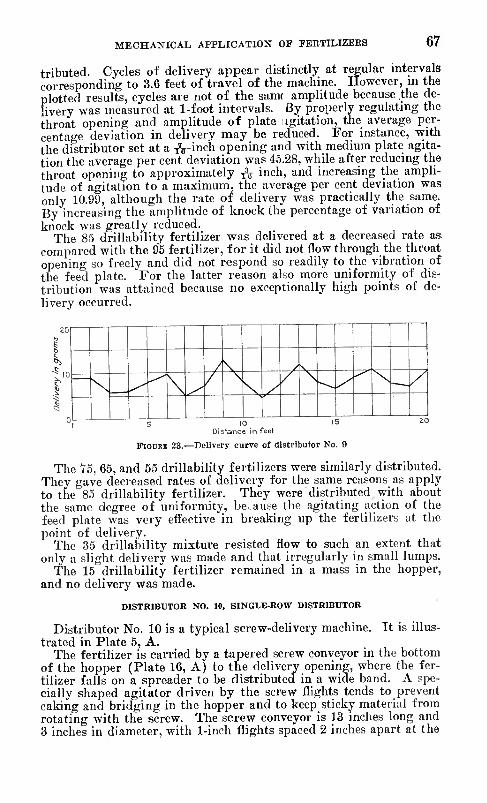
MECHANICAL APPLICATION OF FBRTILIZEES 67
tributed. Cycles of delivery appear distinctly at regular intervals corresponding to 3.6 feet of travel of the machine. However, m the plotted results, cycles are not of the sam( amplitude because the de- livery was measured at 1-foot intervals. By properly regulating the throat opening and amplitude of plate ;igitation, the average per- centage deviation in delivery may be reduced. For instance, with the distributor set at a ^^-inch opening and with medium plate agita- tion the average per cent deviation was 45.28, while after reducing the throat opening to approximately ^ inch, and increasing the ampli- tude of agitation to a maximum, the average per cent deviation was only 1Ü.99, although the rate of delivery was practically the same. By increasing the amplitude of knock the percentage of variation of knock was greatly reduced.
The 85 drillability fertilizer was delivered at a decreased rate as compared with the 95 fertilizer, for it did not flow through the throat opening so freely and did not respond so readily to the vibration of the feed plate. For the latter reason also more uniformity of dis- tribution was attained because no exceptionally high points of de- livery occurred.
20
/ \ / S - 1Ü
\ ^ ̂ \ ^ / \
\ ,/ / \ --. y
>'" N -~ / r 1
U 1 S
D¡- 1
tanc 0 e in "eet
I 5 ao
FlODBK 23.—Delivery curve of distributor No. 9
The 75, 65, and 55 drillabihty fertilizers were similarly distributed. They gave decreased rates of delivery for the same reasons as apply to the 85 drillability fertilizer. They were distributed with about the same degree of uniformity, because the agitating action of the feed plate was very effective in breaking up the fertilizers at the point of delivery.
The 35 drillability mixture resisted flow to such an extent that only a slight delivery was made and that irregularly in small lumps.
The 15 drillability fertilizer remained in a mass in the hopper, and no delivery was made.
DISTRIBUTOR NO. 10, SINGLE-ROW DISTRIBUTOR
Distributor No. 10 is a typical screw-delivery machine. It is illus- trated in Plate 5, A.
The fertilizer is carried by a tapered screw conveyor in the bottom of the hopper (Plate 16, A) to the delivery opening, where the fer- tilizer falls on a spreader to be distributed in a wide band. A spe- cially shaped agitator driven by the screw flights tends to prevent caking and bridging in the hopper and to keep sticky material from rotating with the screw. The screw conveyor is 13 inches long and 3 inches in diameter, with 1-inch flights spaced 2 inches apart at the

68 TECHNICAL BULLETIN 182, U. S. DEPT. OF AGEICULTUEE
rear or delivery end, and 2.5 inches in diameter, with three-fourths inch flights spaced 1.5 inches apart at the front end. The base of the hopper is 10 inches long; thus the fertihzer is carried about 3 inches after leavin<i the hopper before being delivered.
Tlio delivery rate is varied by changing the speed of the screw conveyor which is accomplished by shifting the conveyor drive pinion into mesh with any one of nine concentric gears on the main wheel. The delivery rate used in this study was that corresponding to medium conveyor speed, or the manufacturer's rating of 600 pounds per acre.
The delivery opening is V-shaped, with the point toward the hop- per, the object being to maintain a constant delivery as the charge of fertilizer is carried over the opening. However, a distinct cycle of delivery exists corresponding to each revolution of the screw con- veyor, or 5.22 feet of travel of the machine, and this is the principal cause of uneven distribution. (Fig. 24.)
30
I) \ 1 \ -^ V- Ç20
\ / \ ^ / \ / / \ /
r \ / f—
\ /t \ / \ / ■|'"
—\ \ /
y— \
/ \ -^ / \ /
0
'—
1 s 20
FIGURE 24.-
Distance in feet
-Delivery curve ol distributor No. 10
The cycles of delivery with free-flowing fertilizer are of con- siderable magnitude. Minimum delivery occurs at the instant the screw flight is directly over the point of the delivery opening as shown in Figure 25, A. In this position practically all of one charge of fertilizer has passed through the delivery opening and the suc- ceeding charge can not be delivered until the screw flight has passed over the opening far enough to permit a flow of fertilizer. When the screw flight has passed over the delivery opening far enough to permit a relatively large flow of fertilizer, as shown in Figure 25, B, a free-flowing material will respond very readily, giving a point of maximum delivery.
Distributor No. 10 gives most uniform distribution with medium- drillability fertilizers because the cycles, which are the principal cause of uneven distribution, are of much less amplitude than for the materials of highest and lowest drillability. This implement was designed especially for guano, which has medium drillability.
The fertilizer of 95 drillability flowed freely by gravity through the distributing mechanism when it was stationary, and no results were recorded.
The 85 drillability fertilizer was subject to a high average devia- tion in distribution, 53.65 per cent. This resulted principally from

Tech. Bul. 182. U. S. Dept. of Agriculture
.\, nislribuliiis iiii'cliaiiisiii c. screw deliver.v llitilit; '/, distributor Xo. 10
ir Nu 10, n. (apcred screw C(jTivcyiir; ii. delivery oiK'liiiiK; hopiior. 1!, DislrilHilioii ('[ nil SO drillahilily ferlilizer by

MECHANICAL APPLICATIOIT OF FEETILIZEKS 69
delivery cycles of preat amplitude, which are typical of a free-flowing fertilizer, as explained above. At certain positions of the screw the fertilizer flowed through the distributing mechanism by gravity alone. The distribution of a free-flowing fertilizer is shown in Plate 16, B, the material being 20 to 30 mesh crystaline potassium nitrate having a drillability score of 80. Distinct cycles of delivery are visible, corresponding to 5.22 feet of travel of the machine.
The 75 and 65 drillability mixtures were distributed more uni- formly than the 85 drillability fertilizer. They did not flow from the delivery opening in as finely divided condition, but the amplitude of delivery cycles was greatly reduced. The delivery curves show clearly that the maximum deliveries were lower and that the mini- mum deliveries were higher, indicating a better distribution of the charge. It is evident that the 75 and 65 drillability mixtures did
FIGURE 25.—Positions of delivery screw of distributor No. 10 at points of minimum (A) and maximum (B) delivery: a, tapered screw conveyor; 6, delivery opening; c, screw delivery flight ; e, hopper
not flow out SO rapidly through the narrow part of the delivery opening, and greater amounts of the fertilizers remained in the delivery chamber until the screw was in the position of minimum delivery. The rate of delivery indicates that the screw carried a full charge in each case.
The 55 drillability fertilizer was distributed with the lowest aver- age percentage deviation. Although it was not deposited in a finely divided form, the explanation of the more uniform delivery is the same as that given for the 75 and 65 drillability mixtures. The 55 fertilizer showed no appreciable decrease in rate of delivery and apparently had properties best adapted to the particular design and type of distributor under discussion.
The 35 drillability mixture was distributed with a greater average percentage deviation than the 55 drillability fertilizer, but more uni- formly than the 65, 75, and 85 drillability fertilizers. The reason for this is that the irregularly charged screw, resulting from bridging in the hopper, and the breaking off of the material in lumps from the delivery opening produced uneven distribution regardless of tlie

70 TECHNICAL BXJLLETIIT 182, U. S. DEPT. OF AGBIOULTURE
tendency of this material to flow to the delivery opening at about the same rate during the entire revolution of the screw.
The 15 drillability mixture was delivered unevenly and at a re- duced rate. The screw conveyor was only partially charged, because of the bridging of the fertilizer and its great tendency to adhere in a mass However, there was no great reduction in delivery rate, which is an interesting fact since the other types of distributors gave little or no delivery of this mixture. The material was deposited only m large lumps. , . . . T ^ -, , j
It is worth noting that the 15 drillability mixture was distributed with the same average percentage deviation as the 85 drillability mixture, and probably more uniformly than the 95 driUabihty fer- tilizer would have been distributed had it been possible to control that exceptionally free-flowing material in the distributor.
EUROPEAN TYPES OF DISTRIBUTORS
The chain type of distributor is very common in Europe, but is practically unknown in this country. The Westfalia, Pommerania, Obotrit, and Fricke implements are examples of this type. The fer- tilizer is dispensed from a slit at the bottom of the hopper by obliquely set fingers on an endless chain which moves lengthwise in this opening. The quantity is regulated by the width of the slot and the speed of the chain. As the fertilizer issues from the slot it slides down a board set with pins or falls upon a rapidly revolving studded roller, which spreads it and breaks up masses to secure greater uni- formity of distribution. Over this distributing roller or board a wind shield is hung. Gunness (11) has tried this type of machine at the Massachusetts Agricultural Experiment Station and reports very favorably on it.
Tests (5) were conducted in Germany in 1921 under the direction of the German Agricultural Society to determine the relative merits of 15 distributors entered in a contest sponsored by the German nitrogenous fertilizer committee. The points considered in these tests were uniformity of distribution, row fertilizing, dust prevention, adjustment and management of the machines, and comparative cost of operation and practical value of the distributors.
Each of these 15 machines was of a type different from any of those used in the present study. While the experiments in Germany were under uncontrolled conditions and were rather superficial, neverthe- less the conclusions drawn tend to confirm the results obtained in this investigation.
Several of the machines showed very distinct rhythmic cycles of delivery. Others applied the fertilizer more heavily at the middle of the implement than at the ends. The so-called " slit " machines applied dry fertilizers fairly well but were entirely unsatisfactory with damp materials. Distributors of the chain type (pi. 17, A and B) were best for fertilizers of poor mechanical condition, and the combination chain and spiked-roller type (pi. 18, A and B) gave the best results of all. Spreading boards were of great aid in spreading free-flowing materials evenly, but did more harm than good when the fertilizer was damp or finely powdered. Such material stuck to the board until it built up into quite a mass and then jarred off in

Tech. Bul. 182, U. S. Dept. of Agriculture
■\Vesttalia, chain-type distributor; B, Westfalia, distribuí ing mechanism

Tech. Bul. 182, U. S. Dept. of Agriculture PLATE 18
A, romtnerania. combination chain and spiked-roller distributor; B, Poninierania, distribiiliiiti mechanism; C, English star-wheel distributor

MECHANICAL APPLICATION OF FEETILIZEES 71
lumps. Some of these machines were supplied with devices designed to prevent the raising of dust in filling and operating, but none was entirely satisfactory. Great difficulty was experienced in adjusting the machines so as to secure the desired application rate, but the chain type proved least troublesome in this respect. Practically all of the machines were easily emptied. In distributors of the chain type the bottom is hinged or may be slid out of its position, while those of the other types usually are so arranged that the hopper may be easily tipped over. They appear to have an advantage over most American machines in this regard. A machine 4 meters in width was found to be practicable for a 2-horse team. Implements of this width usually are provided with additional axles or with pivoted wheels for transporting over narrow roads or through gates.
The use of foretrucks on many of these implements lightens the work of the horses, largely eliminates swaying, and reduces tilting of the distributor, thus permitting greater uniformity of distribution of the fertilizer. No machine tested Avas satisfactory in every respect.
A more comprehensive study (6) of fertilizer distributors, which_ in- cludes both laboratory and field tests, was recently conducted in Denmark by the State implement couunittee. Eleven European types of distributors and various ferti- lizers were selected for the study. The construction of the machines, adjustments, and operation are de- scribed in great detail. Uniform- ity of distribution, effect of incli- nation of the machine on delivery rate, and draft for various soil conditions were determined. Other observations and suggestions are also given on the operation and care of distributors.
The top-delivery tj'pe of dispenser, the principle of which is illustrated in Figure 26, is growing in popularity in Europe. This distributor consists of an oblong hopper, usually with a movable bottom that rises steadily as the machine is operated and forces the fertilizer into contact with a revolving paddle wheel at the top of the hopper. On some of those machines the rear liopper wall and paddle wheel descend. The paddles scrape the fertilizer over the rear top edge of the hopper, whence it falls directly to the ground for broadcasting or into collectors for drilling. The rate of delivery depends upon the speed with which the hopper rises or the dispenser descends.
A number of patents ^ have been issued on this type of dis- tributor.
FiGURB 2G.—Section of top-delivery broadcast or row distributor : a, As- cendinjí hopper bottom ; h, iiopper lift- ing pinion ; c, paddle wheel dispenser ; dt stationary rear hopper -wall
»United States: S99399 (1889); 1854414 (1927). German : 46628, 76252 (1894); 2366.31 (1911) ; 257740. 261243 (1913) ; 272948 (1914) ; ,S259Î8 (1920). French, 434833 (1911) ; 513776 (1920). English: 5668 (1901); 142106 (1920). Austrian: 55,382 (1912): 56153 (1912). Swedish: 35995 (1911).

72 TECHNICAL BULLETIN 182, T7. S. DEPT. OF AGRIOITLTUBB
Several reports (7, p. 27i-mO; 10; U, p. 64-^5: 16, p. {83-18^ on the operation of the top-delivery tjrpe have been made. The advantages claimed for it are (1) elimination of the effect of the mechanical condition of the fertilizer upon dehvery rate; (2) even distribution at exceptionally low delivery rates; (3) excellent distribution of fertilizers that are in only fair condition. The dis- advantages are (1) high cost; (2) heavy draft; and (3) a tendency of some fertilizers to pack down and thus slightly change delivery
The star-wheel type of distributor is used in Europe as well as in this country. Plate 18, C, illustrates one of English make.
In 1927 an entirely new type of distributor (ßO, f. 7), fundamen- tally different from any other, was put on the market in Germany. The machine consists of a flat-lying hopper in the form of a 3-sided frame, having no front wall or'bottom. The frame rests and moves upon a fixed table. The desired quantity of fertilizer for applica- tion upon one-half acre is spread in the hopper and the top is fas- tened down upon it, thus giving a layer of fertilizer of uniform thickness held between the top and bottom plates somewhat like a sandwich. In operation the top and rear wall of the hopper move forward, shoving the contents with them. The fertilizer falls upon a rapidly revolving roller which scatters it. The machine is so geared that the hopper empties itself as just one-half acre has been traversed. The entire implement, including gears, is constructed of moisture-proofed wood.
FACTORS AFFECTING THE OPERATION OF DISTRIBUTORS
The factors studied in relation to the operation of distribution were depth of fertilizer, inclination of the distributor, variations in delivery units, unrestricted flow of fertilizer, efficiency of agitators, feed-wheel speed, and amount of positive delivery action.
DEPTH OF FERTILIZER IN THE HOPPER
Three series of experiments were performed to determine the effect of head or depth of fertilizer on delivery rate. This was done by filling the hopper and measuring the rate at intervals until the hopper had been emptied.
The first series was performed to determine the effect of the fertilizer properties. Four different fertilizers—commercial 3-9-3 mixture, potassium nitrate, fish scrap, and urea-ammonium phos- phate—were used with distributor No. 1 in an atmosphere of 86° F. and 30 per cent relative humidity. The 3-9-3 mixture was similar to many mixed fertilizers now on the market. The crystalline potassium nitrate was screened to pass a 20-mesh but not a 40-mesh sieve. The fish scrap was a characteristic sample containing flakes and fishbones, thus giving it mechanical properties somewhat differ- ent from those of the other materials. The urea-ammonium phos- phate was similar in appearance and physical properties to commer- cial ammonium sulphate or urea.
The results given in Table 27, show that the rate of delivery is dependent to some extent on head, but varies with different ferti- lizers. When the head of material was equal to or greater than 5

MECHANICAL APPLICATION OF FBRTILIZEES 73
inches, no appreciable variations in delivery rates occurred with changes of the head. However, at different depths of fertilizer be- low 5 inches a material variation in delivery rates will be noted, the rate at 5 inches being from 5 to 9 per cent higher than that at a 2-inch head. The width of the hopper at the gate opening being 5 inches in this case, the conclusion seems to be warranted that in- creasing the head above that equal to the width of the hopper has little or no effect upon the delivery rate. This conclusion was sub- stantiated in the second series of tests.
TABLE 27.—Effect of head upon delivery rate of various fertilizers b¡i No. 1 distributor
Depth of fertilizer (Inches)
Delivery rate per acre
Commercial 3-9-3 20-Í0 mesh potas- sium nitrate Fish scrap
Pints 82 16 85.38 87.72 89 48 90.94 91.82 87.42 86.84
Urea-ammonium phosphate
Pounds 68.49 69.94 71.15 71.87 72.60 73.33 73.08
Pints 93.82 95.80 97.47 98.45 99.45
100.45 100. 11
Pounds 86.64 89. 54 91.96 92.20 92.25 92.20 91.96 91.72
PiTlls 94.17 97.33 99.95
100. 22 100.27 100.22 99.96 99.70
Pounds 41.08 42. 69 43.86 44.74 4.5.47 45.91 43.71 43.42
Pounds Pint» 55.18 84.89 67.11 1 87.86 68.32 89. 72
5 _ 59.05 1 90.84 69.53 91.68
7 69. 77 1 91.95 8 - 60.00 i 92 31 9 - 72.84 99.78 60.02 1 92.34
Major Phillips first observed that a downward force applied to a column of dry sand in a cylinder is not transmitted to the bottom if the height of the column is more than twice its diameter, the reason being that the additional pressure is borne by the walls of the con- tainer because of a bridging effect in the sand {19).
The second series of tests was conducted with granulated potas- sium-ammonium phosphate having a drillability score of 85, to show the effect of head upon delivery rate for nine different dis- tributors. (Table 28.) It will be observed that this effect varies greatly in different types of distributors and that it was very pro- nounced at low heads in every instance, except for distributor No. 8.
TABLE 28.- -Effect of head upon deliver]/ rate of 85 drillaMUty fertilizer by various distributors
Head of fertilizer (inches)
Pounds per acre delivered by distributor No.
1 2 3 5 6 7 8 9 10
1 285 303 322 325 328 331 331 333
360 382 389 391 392 398 406
(■) 416 492 528 514 486 470 470 472 475 485 487 499 605 609
(') 1.468
80 89
(') , 198 638 198 539 1 198 640 108 542 1 199 .543 ! 199
(■) 1,630 1,651 1,579 1,,572 1,559 1,549 1,546 1,.579 1,582 1,682 1,679
(') 2 733 3 1,569 : 98
1.618 ' 101 735
4 _ 737 5 1,625
1,631 1,630 1,639 1,652 1,655 1,655 1,652
102 103
738 6 . -. , 741 7 103 : ,543 ' 200 743 8 104 Í 546
104 1 545 201 204 207 209
746 10 741 12 548 744 14 643 744 16 18 20 23
1 Impossible to maintain a constant head.

74 TECHNICAL BULLETIN 182, U. S. DEPT. OF AGEIOULTTJRB
One general conclusion drawn from these tests was that in all bot- tom-delivery types of distributors, changes of head had little or no effect on delivery rate when the depth of fertilizer was greater than the width of the hopper at the discharge opening. However, when little. fertilizer remained in the hopper, changes of head had a marked effect ; in several such instances changing the head from 2 to 4 inches varied the delivery rate by as much as 10 per cent.
Obviously, in the case of distributor No. 8, which is of the top- delivery type, any increased delivery rate attributable to greater head, must be ascribed to a compacting of the fertilizer. With this distributor the head shown in Table 28 is not the actual depth of material in the hopper, but represents the maximum pressure to which the particular fertilizer being delivered had been subjected when the hopper was filled. In this case there is little or no varia- tion in the delivery rate at low heads, but any significant changes that occur will be found at the greater heads. This is explained by the fact that during the operation of the machine the lower heads are delivered first and there is not suiRcient time for the material to settle, while the greater heads .are delivered after the machine has been operated for some time and the fertilizer has settled and is more compact. It has been found that the effect on delivery rate depends upon the amount of settling, which, in turn, depends upon the character of the material. For instance, a material composed of large, regularly shaped, hard particles will not settle as much as one made up of rough particles mixed with a high percentage of fine material.
Table 28 shows that with distributors Nos. 3 and 9 the delivery rate increased as the head was increased from 2 to 4 inches, then decreased until an 8-inch head was reached, after which there was a gradual increase. The presence here of a high point in the delivery rate with a 4-inch head resulted from segregation of the material in the hopper. At or near a 4-inch head the fertilizer directly above the throat opening was moved with the hopper bottom and vigorously agitated. This produced rapid separation of fine material from the coarse, thus permitting the coarser material to flow out on the deliv- ery plate as a separate mass. The coarser material, flowing much more readily than the finer material or the mixture of coarse and fine material, increased the delivery rate, as already explained under the heading " Operation of distributors." At heads of about 8 inches or greater, the surface of the fertilizer in the hopper was not carried about or vigorouslj^ agitated ; thus no opportunity was afforded for very rapid segregation.
Head is of some importance even with materials now commonly used. The maximum reduction in delivery rate during emptying of the hopper was 23 per cent. In the case of distributor No. 8 there was a slight increase in the delivery rate.
The third series of tests was conducted primarily to determine the maximum effect of head that might be encountered. The more freely a fertilizer will flow the greater the effect of head will be. Centrifugally sprayed potassium nitrate, being the freest flowing material available, was used for these tests. Several types of ma- chines were tested. The experimental results are presented in Table 29.

MECHANICAL APPLICATION OF FEETILIZEBS 75
TABLE 29.—Delivery rates of 95 drillability fertilizer (centrifugally sprayed potassium nitrate) showing maximum effect of head
Distributor ' No.
1.
2.
6.
8
9,
Inches 1.60 5.60 2.25 5.75 1.60 3.50 1.00 5.20 2.75 5.60
Cliange of bead
Inches
4.0
2.0
Delivery
Orams 492.7 568.3
1, 205. 6 1,312.3
690.2 944.7 680.56 680.50 653. 5 737.6
Increase of delivery
Per cent 15.34
8.86
60.06
0
12.87
1 Tile fertilizer flowed unrestrictedly througli the distributing mechanism in distributors Nos. 4, 6, 7 and 10, which made testing impossible but indicated that effect of head would be very significant.
The results indicate that any change in a comparatively low initial head of free-flowing fertilizer has considerable effect on rate of delivery. The one exception to this is No. 8 distributor, the explanation for which has been given (p. 74).
An extreme case appears with distributor No. 6, where increasing the head from 1.5 inches to 3.5 inches increased the delivery rate 60 per cent. Head acted in this case in such a way as to be very effec- tive. It did not have much effect in compacting the fertilizer to be delivered, but it determined the height of the fertilizer on the shielded part of the feed plate. The quantity of fertilizer delivered by the plow being in turn dependent on the depth of fertilizer on the plate, only a slight change in the depth is necessary to materially change the delivery rate. Head also functions effectively in this case by reason of the free-flowing qualities of the fertilizer which permit the particles to readjust themselves during the gradual charging of the feed plate. A head of 1.5 inches brought the level of the fertilizer on the shielded part of the feed plate 0.25 inch above the throat opening, whereas, under the same conditions, materials with the usual properties would not have been raised above the throat opening.
INCLINATION OF DISTRIBUTOR
Distributors which depend in any way upon gravity for unload- ing, as most of them do, deliver at different rates when the machine is inclined from its normal operating position, as for instance when traveling over sloping parts of a field. The difference in delivery rate is due primarily to a change in the direction of the_ force of gravity with reference to the outlet in the feeding mechanism.
Distributors show greater differences in delivery rate when tilted forward or rearward than when tilted to either side. One- row distributors which are held upright by the operator usually may be operated in hilly country without much inclination of the machine if the rows follow contours. Wide distributors such as lime spreaders and grain, beet, and grass seed drills are subject to lateral inclination on sloping ground.
Distributor No. 2 was operated in the constant-humidity room at various inclinations to the front and rear at atmospheric conditions of 68° F. and 40 per cent relative humidity. The gate-control lever was set at notch 15. The results obtained are presented in Table 30.
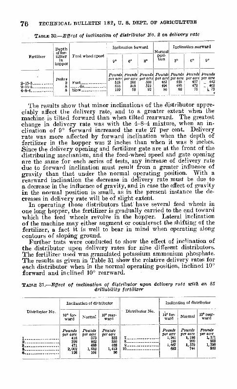
76 TECHNICAL BULLETIN 182, V. S. DEPT. OF AGEICULTUKB
TABLE 30.—Effect of inclination of digtrilutor No. 2 on delivery rate
Fertilizer
2-15-5 2-15-6 4-»-4.
Depth of fer- tilizer
in hopper
Inches 2
Feed wheel speed
Fast... do Slow..
Inclination forward
Pounds per acre
618 633 109
Pounds per acre
606 613
Pounds per acre
600 612
92
Normal posi- tion
Pounds per acre
453 494
Inclination rearward
Pounds per acre
468 486 80
Pounds, Pound» per acre\ per acre
457 442 472 I 462
76 L 73 I •<
The results show that minor inclinations of the distributor appre- ciably affect the delivery rate, and to a greater extent when the machine is tilted forward than when tilted rearward. The greatest change in delivery rate was with the 4-8^ mixture, when an in- clination of 9° forward increased the rate 27 per cent. Dehvery rate was more affected by forward inclination when the depth of fertilizer in the hopper was 2 inches than when it was 8 inches. Since the delivery opening and fertilizer gate are at the front of the distributing mechanism, and the feed-wheel speed and gate opening are the same for each series of tests, any increase of delivery rate due to forward inclination must result from a greater influence of gravity than that under the normal operating position. With a rearward inclination the decrease in delivery rate must be due to a decrease in the influence of gravity, and in case the effect of gravity in the normal position is small, as in the present instance the de- creases in delivery rate will be of slight extent.
In operating those distributors that have several feed wheels in one long hopper, the fertilizer is gradually carried to the end toward •which the feed wheels revolve in the hopper. Lateral inclination of the machine may either augment or counteract the shifting of the fertilizer, a fact it is well to bear in mind when operating along contours of sloping ground.
Further tests were conducted to show the effect of inclination of the distributor upon delivery rates for nine different distributors. The fertilizer used was granulated potassium ammonium phosphate. The results as given in Table 31 show the relative delivery rates for each distributor when in the normal operating position, inclined 10° forward and inclined 10° rearward.
TABLE 31.—Effect of inclination of distributor upon delivery rate vñtTi an 85 drillability fertilizer
Inclination of distributor
Distributor No.
Inclination of distributor
Distributor No. 10° for- ward Normal 10° rear-
ward lb° for- ward Normal 10° rear-
ward
1
Pounds per acre
416 399 471
2,002 126
Pounds per acre
373 362 488
1,652 104
Pounds per acre
333 330 488
1,413 90
7
Pounds per acre
1,241 199
1,667 692
Pounds per acre
1,186 200
1,679 744
Pounds per acre
1,171 2 8 200
9 1,790 S - - 10 840 6..
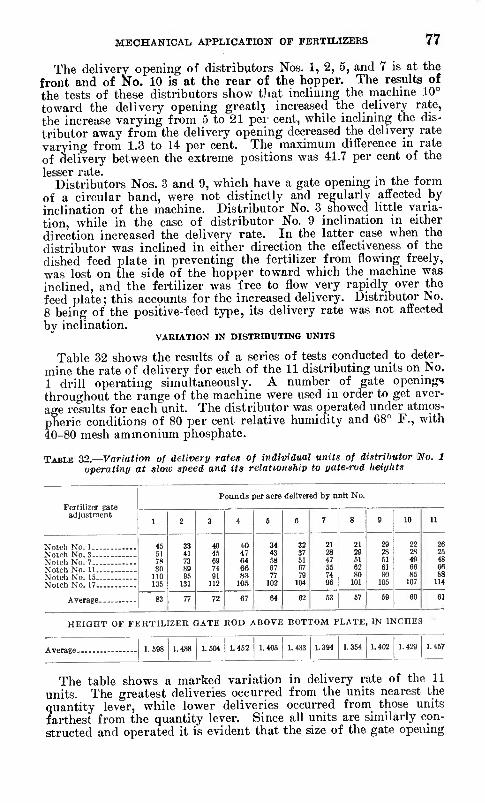
MECHANICAL, APPLICATIOÜT OF FEBTILIZBES 77
The delivery opening of distributors Nos. 1, 2, 5, and 7 is at the front and of No. 10 is at the rear of the hopper. The results of the tests of these distributors show that inclining the machine 10° toward the delivery opening greatlj increased the delivery rate, the increase varying from 5 to 21 per cent, while inclining the dis- tributor away from the delivery opening decreased the delivery rate varying from 1.3 to 14 per cent. The maximum difference in rate of delivery between the extreme positions was 41.7 per cent of the lesser rate
Distributors Nos. 3 and 9, which have a gate opening in the form of a circular band, were not distinctly and regularly affected by inclination of the machine. Distributor No. 3 showed httle varia- tion, while in the case of distributor No. 9 inclination in either direction increased the delivery rate. In the latter case when the distributor was inclined in either direction the effectiveness of the dished feed plate in preventing the fertilizer from flowing freely, was lost on the side of the hopper toward which the machine was inclined, and the fertilizer was free to flow very rapidly over the feed plate ; this accounts for the increased delivery. Distributor No. 8 being of the positive-feed type, its delivery rate was not affected by inclination.
VARIATION IN DISTRIBUTING UNITS
Table 32 shows the results of a series of tests conducted to deter- mine the rate of delivery for each of the 11 distributing units on No. 1 drill operating simultaneously. A number of gate openings throughout the range of the machine were used in order to get aver- age results for each unit. The distributor was operated under atmos- pheric conditions of 80 per cent relative humidity and C8° F., with 40-80 mesh ammonium phosphate.
TABLE 32.—Variation of delivery rafes of ivdividual units of distrihutor No. 1 uperatiny at slow speed and its relationship to yate-rud heiyltts
Ferlillzer gate adjustment
Pounds per acre delivered by unit No.
1 2 3 4 S 6 7 8 9 10 11
45 61 7S 80
110 135
33 41 73 89 95
131
40
69 74 91
112
40 47 64 66 83
ICi
34 43 58 67 77
102
32 37 61 67 79
104
21 28 47 65 74 96
21 29 61 62 80
101
29 28 61 61 80
105
22 2S 4!) 66 86
107
26 Notch Ko. 3 25
48 66 88
Notch No. 17 114
Average 83 77 72 67 64 62 63 67 69 60 61
HEIQHT OF FERTILIZER GATE ROD ABOVE BOTTOM PLATE, IN INCHES
Average. 1.488 1.452 1.402
The table shows a marked variation in delivery rate of the 11 units. The greatest deliveries occurred from the units nearest the quantity lever, while lower deliveries occurred from those units farthest from the quantity lever. Since all units are similarly con- structed and operated it is evident that the size of the gate opening
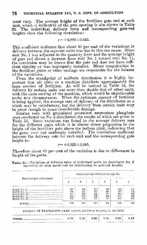
78 TECHNICAL BULLETIN 182, TT, S. DEPT. OF AGKICULTUBE
must vary. The average height of the fertilizer gate rod at each unit, which is indicative of the gate opening is also shown in Table 32. The individual delivery rates and corresponding gate-rod heights show the following correlation :
r=+0.889 ±0.043.
This coefficient indicates that about 80 per cent of the variations in delivery between the separate units was due to this one cause. Since unit No. 1 was adjacent to the quantity lever and the average height of gate rod shows a decrease from unit No. 1 toward unit No. 11, the conclusion may be drawn that the gate rod does not have suffi- cient rigidity or was improperly installed. Minor irregularities in the fertilizer gates or other castings are responsible for the balance of the variations.
From the standpoint of uniform distribution it is highly im- portant that all units on a machine distribute approximately the same amount of fertilizer. As will be noticed in Table 32, the delivery by certain units was more than double that of other units, with the same setting of the machine, which would be objectionable under any circumstances. When the optimum amount of fertilizer is being applied, the average rate of delivery of the distributor as a whole may be satisfactory, but the delivery from certain units may be great enough to cause considerable damage.
Similar tests with granulated potassium ammonium phosphate were conducted on Ño. 2 distributor, the results of which are given in Table 33. Some variation was found in the average delivery rate for the different units which is in almost direct proportion to the height of the fertilizer gate above the bottom plate, indicating that the gates were not uniformly installed. The correlation coefficient between the delivery rate for each unit and the corresponding gate height is :
r=+0.923 + 0.045.
Therefore about 85 per cent of the variation is due to differences in height of the gates.
TABLE 33.—Variation of delivery rates of individual units for distributor No. 2 operating at slow speed and its relationship to gate-rod heights
Pounds per acre delivered by unit No.
1 2 3 ! 4 ! 6 6
Notch No 1 . . ,. 187 195 255 391 543
184 195 282 420 653
155 ^ 146 165 ' 168 244 : 271 369 ; 404 521 j 675
152 16S 266 412 653
155 174 266
Noloh No 15 - 404 Notch No 20 - 653
314 327 291 313 310 310
HEIGHT OF FERTILIZER GATE ABOVE BOTTOM PLATE, IN INCHES
Average-

MECHANICAL APPLICATION OF FERTILIZEKS 79
Distributor No. 3 has two delivery tubes leading from the distrib- uting unit for applying fertilizer on both sides of the row. The division is accomplished by permitting the stream of fertilizer com- ing from the plow to fall on the fixed junction of the tubes. How- ever, the center of mass of the stream of fertilizer will change with different fertilizers and at different rates of delivery. A series of tests with five different kinds of fertilizers and at five different rates of deliveries were made to show to what extent division of the fertilizer was affected. The results are given in Table 34.
TABLE 34.—Delivery rates in pounds per acre of various fertilizers hy right and left tubes of distributor No. 3
Notch No. '
Ammonium sulphate
Potassium nitrate
Superphos- phate
3-9-3 commer- cial
8-12-20 com- ' mercial
Right tube.
Left tube
KiRht tube
Left tube
Right tube
Left tube
Right tube
Left tube
Pounds 173
RiEht tube
Lett tube
1 Pounds
178 193 223 374 GOl
Pounds 22Ü 282 347 375 477
Pounds 147 209 376 697 972
Pounds 170 211 229 350 642
Pounds 273 279 340 461 635
Pounds 152 257 367 565 774
Pounds 136 168 238 475 608
Pounds 19!
Poundt 184
2 - 3- -
225 263 402 445
240 C90 968
1,368
244 286 776
5 - 1,014
I Notch refers to the position of the fertilizer plow as indicated on an arbitrary scale placed on the hopper during the experiment.
"When the sum of the delivery rates of the two tubes was approxi- mately COO pounds per acre, all the fertilizers seemed to be quite evenly divided. When the rate of delivery was low a greater part of the fertilizer passed over the feed-plate wall at a point near the plow and into the left tube, and when the delivery rate was high the fertilizer piled up for a considerable distance in front of the plow and flowed over the plate wall in a wide stream, the greater part passing into the right tube, except in the case of the superphosphate. This fertilizer was finely powdered and somewhat damp. At low rates of delivery some of it adhered to the front of the plow and diverted the flow over the plate wall at such a point so that the greater part fell into the right tube. At high rates of delivery this fertilizer had a tendency to flow as a column over the plow, and a greater part of the delivery was directed into the left tube.
A consistent and significant variation in the delivery from the tubes of distributor No. 3 was also noted from the standpoint of segregation accoi-ding to size of particles. The material used was granulated potassium-ammonium phosphate, and the delivery rate of tlie machine was 505 pounds per acre, divided 196 pounds from the right tube and 309 pounds from the left tube. The percentages of various particle sizes as delivered by each tube are given in Table 35. It will be observed that a smaller percentage of the large par- ticles and a greater percentage of the small particles were delivered through the left tube. The most striking variation was with the 30-50 mesh particles, in which case 15.18 per cent of the total delivery from the left tube and only 1.58 per cent of that from the right tube consisted of this size of material.
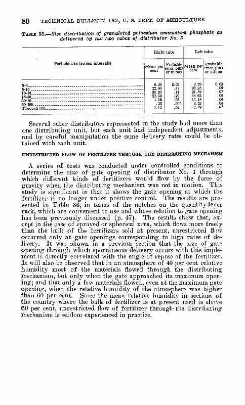
80 TECHNICAL BULLETIN 182, U. S. DEPT. OF AGEIOULTUEB
TABLE 35. Size distribution of granulated potassium ammonium phosphate as delivered by the two tubes of distributor No. S
Particle size (screen Intervals) Mean per
cent
3-5 6-10 10-1(1 16-30 30-60 60-100 Through 100.
Right tube
Probable error, plus or minus
0.26 22.90 36.20 37.69
1.68 .23
1.16
0.03 .42 .H .29 .03 .005 .02
Left tube
Mean per cent
0.29 20.25 21.59 36.03 15.18 3.52 2.59
Probable iTror, plus or minus
0.03 .09 .07 .06 .06 .04 .07
Several other distributors represented in the study had more than one distributing unit, but each unit had independent adjustments, and by careful manipulation the same delivery rates could be ob- tained with each unit.
UNRESTRICTED FLOW OF FERTILIZER THROUGH THE DISTRIBUTING MECHANISM
A series of tests was conducted under controlled conditions to determine the size of gate opening of distributor No. 1 through which different kinds of fertilizers would flow by the force of gravity when the distributing mechanism was not in motion. This study is significant in that it shows the gate opening at which the fertilizer is no longer under positive control. The results are pre- sented in Table 36, in terms of the notches on the quantity-lever rack, which are convenient to use and who.se relation to gate opening has been previously discussed (p. 47). The results show that, ex- cept in the case of sprayed or spherical urea, which flows more freely than the bulk of the fertilizers sold at present, unrestricted flow occurred only at gate openings corresponding to high rates of de- livery. It was shown in a previous section that the size of gate opening through which spontaneous delivery occurs with this imple- ment is directly correlated with the angle of repose of the fertilizer. It will also be observed that in an atmosphere of 40 per cent rehitive humidity most of the materials flowed through the distributing meclianism, but only when the gate approached its maximum open- ing; and that only a few materials flowed, even at the maximum gate opening, when the relative humidity of the atmosphere was higher than 60 per cent. Since the mean relative humidity in sections of the country where the bulk of fertilizer is at present used is above 60 per cent, unrestricted flow of fertilizer through- the distributing mechanism is seldom experienced in practice.

MECHANICAL APPLICATION OF FERTILIZEES 81
lABLB 36.- -Oate adjustment permitting unrestricted flow of fertilizers through the distributing mechanism of distributor No. 1
Fertilizer
Ordinary fertilizer materials: Superpliosphate Sulpliate of ammonia Nitrate of soda _-_ Fish scrap --_ Cottonseed meal Peat
Concentrated materials: Urea, sprayed Urea, granulated Urea, powdered. Ammonium nitrate. _ Leunasalpeter Ammo-phos Monoararaonium phosphate Diamraonium phosphate Triple superphosphate.__ __ Potassium-ammonium phosphate. Monopotassiura phosphate Potassium nitrate Trona potassium chloride ___
Ordinary commercial mixtures: 2-8-.') 3-9-3 4-S-4.
Concentrated commercial mixtures: 4-16-10 - 4-24-4. 8-16-8 10-16-14..
Concentrated mixtures: No. 3 No. 4 No. 6
Qate adjustment at percentage relative humid- ity oí—
40
Notch 22 15 16 23
(') 17
5 17
(') 17 21 24 IB 17 23
(') 18 17 17
24 20
60 60 70 80
Notch Notch Notch Notch (') (') <'! (') (') ') (') (')
17 22 « (') 24 24 27 25
(') (') (0 (') 17 18 16 17
5 9 14 m IS 22 (') ('S
(') ('/ (') (') (') c: (') (ï) 26 c: (■) (') 22 21 24 (') 17 17 21 ('S 19 24 (') ('S 23 24 25 30
(') (') (') (') 18 20 (') Cj 18 22 (') 0: 24 (') (') (') 26 (') (') <■') 27 30 c; (' 28 (') (') ('S 20 20 (') (') 24 26 27 (') 18 20 24 (') 18 20 (') (') 30 (') (') (') 24 (') (') (') 22 (') (') (')
00
Notch (')
('Í ('S (') ('} (>
* No unrestricted flow at maximum gate opening. > Too damp for testing. I Decomposed.
If an attempt is made in dry weather to distribute more than 600 pounds per acre of free-flowing fertilizer with this type of machine, one should make sure that the material is not escaping from the distributor while it is idle.
In other types of distributors free-flowing fertilizer may or may not pass through the distributing mechanism when the machine is not in operation. For instance, distributors like Nos. 3, 6, and 8 are not subject to unrestricted flow of the fertilizer through the dis- tributing mechanism, since there is no opportunity for free passage of the material into the delivery tube by gravity flow.
Some difficulty was experienced with all types of distributors, due to free-flowing fertilizer escaping through small openings in the hopper. Under ordinary conditions commercial fertilizers usually do not flow freely enough to give much trouble in this respect.
USE OF AGITATORS
Delivery rate was not affected by the use of an agitator with high- drillability fertilizers, and was affected appreciably only when the fertilizer was in such condition as to bridge over the delivering mechanism. When the fertilizer had exceptionally low drillability
98734—30 6
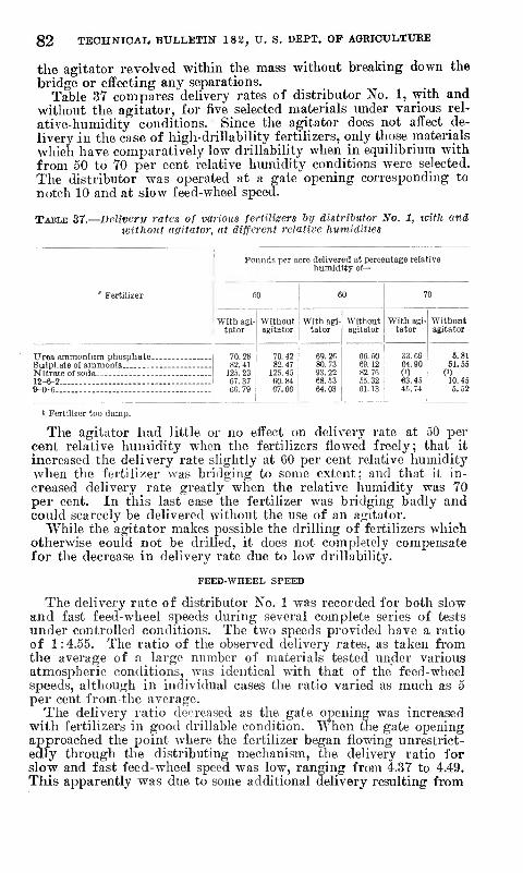
82 TECHNICAL, BULLETIN 182, U. S. DEPT. OP AGRICULTUEE
the agitator revolved within the mass without breaking down the bridge or effecting any separations.
Table 37 compares delivery rates of distributor No. 1, with and without the agitator, for five selected materials under various rel- ative-humidity conditions. Since the agitator does not affect de- livery .in the case of high-drillability fertilizers, only those materials -which have comparatively low drillability when in equilibrium with from 50 to 70 per cent relative humidity conditions were selected. The distributor was operated at a gate opening corresponding to notch 10 and at slow feed-wheel speed.
TABLE 37.—Delivery rates of various fertilizers hy distributor No. 1, with and tmthout agitator, at different relative humidities
Pounds per acre delivered at percentage relative humidity of—
' Fertilizer 60 60 70
With agi- tator
Without agitator
With agi- tator
Without agitator
With agi- tator
Without agitator
Urea ammonium phosphate ._ 70.28 82.41
70.42 82 47
125. 45
69.26 80.73 93.22
66. 60 ! 33.69 69. 12 1 64.90 82. 76 1 (')
6.81 Sulphate of ammonia 61.65
12.'). 23 (') 12-6-2 .__ 9-0-6—
67.37 60.79
60.84 67.66
68.53 64.03
65.32 61.13
63.45 45.74
10.48 6.62
Ï Fertilizer too damp.
The agitator had little or no effect on delivery rate at 50 per cent relative humidity when the fertilizers flowed freely; that it increased the delivery rate slightly at 60 per cent relative humidity when the fertilizer was bridging to some extent; and that it in- creased delivery rate greatly when the relative humidity was 70 per cent. In this last case the fertilizer was bridging badly and could scarcely be delivered without the use of an agitator.
While the agitator makes possible the drilling of fertilizers which otherwise could not be drilled, it does not completely compensate for the decrease in delivery rate due to low drillability.
FEED-WHEEL SPEED
The delivery rate of distributor No. 1 was recorded for both slow and fast feed-wheel speeds during several complete series of tests under controlled conditions. The two speeds provided have a ratio of 1:4.55. The ratio of the observed delivery rates, as taken from the average of a large number of materials tested under various atmospheric conditions, was identical with that of the feed-wheel speeds, although in individual cases the ratio varied as much as 5 per cent from the average.
The delivery ratio decreased as the gate opening was increased with fertilizers in good drillable condition. When the gate opening approached the point where the fertilizer began flowing unrestrict- edly through the distributing mechanism, the delivery ratio for slow and fast feed-wheel speed was low, ranging from 4.37 to 4.49. This apparently was due to some additional delivery resulting from
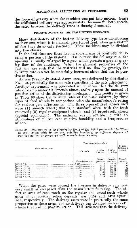
MECHANICAL APPLICATION OF FEKTILIZEES 83
the force of gravity when the machine was put into motion. Since the additional delivery was approximately the same for both speeds, the ratio between the delivery rates is thereby decreased.
POSITIVE ACTION OF THE DISTRIBUTING MECHANISM
Many distributors of the bottom-delivery type have distributing mechanisms, which it is claimed, give forced feed, when as a matter of fact they do so only partially. These machines may be divided into two classes.
In the first class are those having some means of positively deliv- ering a portion of the material. To increase the delivery rate, the opening is usually enlarged by a gate which permits a greater grav- ity flow of the substance. When the physical properties of the fertilizer are such that the material will not flow by gravity, the delivery rate can not be materially increased above that due to posi- tive action.
As was previously stated, damp urea, was deHvered by distributor No. 1 at practically the same rate regardless of the gate adjustment. Another experiment was conducted which shows that the delivery rate of damp materials depends almost entirely upon the amount of positive action of the distributing mechanism. The results as given in Table 38 show the delivery rates of the 3-9-3 mixture, by three types of feed wheels in comparison with the manufacturer's rating for various gate adjustments. The three types of feed wheels used were (1) smooth wheel; that is, a standard wheel with the teeth removed; (2) regular-equipment wheels ; and (3) broad-teeth wheels (special equipment). The material was in equilibrium with an atmosphere of 80 per cent relative humidity and a temperature of 68°.
TABLE 38.—Delivery rates by distrihutor No. 1 of the S-9-S commercial fertilizer in equiUhrium with 80 per cent relative humidity, by different deyreea of positive action, as compared with manufacturer's rating
Tooth-face dimensions Manu-
Gate adjustment No teeth 0.10 by
0.98 inch 0.39 by
1.1 inches
facturer's rating
Pounds per acre Pounds per acre
7.12 8.13 8.13 8.71
11.03 14.08 17.28
Pounds per acre
20.76 27.30 29.04 29.62 33.11 38.04 40.61
Pounds per acre
30 do 45 do 80
. do 116 do_ 171 do 220
Notch No 30 do 250
When the gates were opened the increase in delivery rate was very small as compared with the manufacturer's rating. The ef- fective area of each tooth on the regular and broad-teeth wheels upon which positive action depends, was 0.157 and 0.429 square inch, respectively. The delivery rates were in practically the same proportion as these areas, and no delivery was obtained with smooth wheels that had no positive action. This indicates that the delivery

84 TECHNICAL, BULLETIN 182, TJ. S. DEPT. OF AORIOULTTTKE
of materials of poor drillability is almost entirely dependent upon the positive action of the dispensing parts.
In the second class are those machines, of which No. 4 is an ex- ample, that have a means of positively delivering the fertilizer into the delivery tube but which depend almost entirely upon gravity to transfer the material from the hopper to the positive-acting parts. In this case the delivery rate for each adjustment of the fertilizer grate will depend to a large extent upon the gravity flow of the mate- rial. A damp material that does not flow by gravity will be delivered at a greatly reduced rate or not at all, as has been shown in Table 26.
Top-delivery types of distributors are wholly positive in their action.
UNIFORMITY OF DISTRIBUTION
The manner of applying fertilizers to crops has considerable effect upon the results to be obtained from their use. This may be considered from two standpoints: (1) The position of the fertilizer in reference to the seed, and (2) the uniformity of distribution. The subject has been carefully studied from the first standpoint by a number of investigators, and Truog and Jensen (21 p. 33-55) have published an extended bibliography of such work.
From theoretical considerations the application of the same amount of fertilizer to each plant appears to be as important as the particular location of variable amounts with respect to the seed, piovided the fertilizer is not in contact with the seed. The desirabil- ity of uniform distribution for securing the most profitable returns has long been recognized {15). The subject has received practically no attention, however, from research workers, so far as one can judge from the literature—a condition probably due to the conviction that distributors generally apply fertilizers very evenly. The fact that they do not has been recognized in Germany, but only in a qualitative way. Fischer (5) points out the great difficulty of ob- taining satisfactory distribution of small quantities of fertilizer in good condition, and the impossibility of obtaining it when the fertil- izers are damp. He also discusses several types of German distribu- tors in this respect, viertens (17) likewise found that distributors did not give uniform distribution.
Damp or finely powdered substances or those composed of oblong crystals will not flow freely, if at all. Distributors differ in the way they handle fertilizers that will not flow, but in practically every such case the fertilizer is delivered more or less irregularly. For example, slightly damp, powdered urea was found to issue from the delivery spouts of a star-wheel type distributor only when a tooth of the feed wheel passed over the opening in the bottom plate. Such delivery is very unsatisfactory because as much as an ounce of ferti- lizer may be dropped in one spot while in the succeeding 5 or 10 feet none is applied. This is an extreme case, but in the best results obtained during the entire series of tests in this study the average deviation was 6.33 per cent from the mean and at least 1 out of every 10 intervals of delivery used in calculating this average deviated more than 15 per cent.
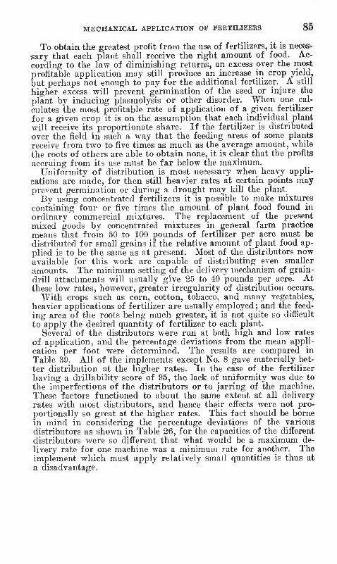
MECHANICAL APPLICATION OF FERTILIZEES 85
To obtain the greatest profit from the use of fertilizers, it is neces- sary that each plant shall receive the right amount of food. Ac- cording to the law of diminishing returns, an excess over the most profitable application may still produce an increase in crop yield, but perhaps not enough to pay for the additional fertilizer. A still higher excess will prevent germination of the seed or injure the plant by inducing plasmolysis or other disorder. When one cal- culates the most profitable rate of application of a given fertilizer for a given crop it is on the assumption that each individual plant will receive its proportionate share. If the fertilizer is distributed over the field in such a way that the feeding areas of some plants receive from two to five times as much as the average amount, while the roots of others are able to obtain none, it is clear that the profits accruing from its use must be far below the maximum.
Uniformity of distribution is most necessary when heavy appli- cations are made, for then still heavier rates at certain points may prevent germination or during a drought may kill the plant.
By using concentrated fertilizers it is possible to make mixtures containing four or five times the amount of plant food found in ordinary commercial mixtures. The replacement of the present mixed goods by concentrated mixtures in general farm practice means that from 50 to 100 pounds of fertilizer per acre must be distributed for small grains if the relative amount of plant food ap- plied is to be the same as at present. Most of the distributors now available for this work are capable of distributing even smaller amount.s. The minimum setting of the delivery mechanism of grain- drill attachments will usually give 25 to 40 pounds per acre. At these low rates, however, greater irregularity of distribution occurs.
With crops such as corn, cotton, tobacco, and many vegetables, heavier applications of fertilizer are usually employed ; and the feed- ing area of the roots being much greater, it is not quite so difficult to apply the desired quantity of fertilizer to each plant.
Several of the distributors were run at both high and low rates of application, and the percentage deviations from the mean appli- cation per foot were determined. The results are compared in Table 39. All of the implements except No. 8 gave materially bet- ter distribution at the higher rates. In the case of the fertilizer having a drillability score of 95, the lack of uniformity was due to the imperfections of the distributors or to jarring of the machine. These factors functioned to about the same extent at all delivery rates with most distributors, and hence their efl^ects were not pro- portionally so great at the higher rates. This fact should be borne in mind in considering the percentage deviations of the various distributors as shown in Table 26, for the capacities of the different distributors were so different that what would be a maximum de- livery rate for one machine was a minimum rate for another. The implement which must apply relatively smail quantities is thus at a disadvantage.

86 TECHNICAL BULLETIN 18 2, U. S. DEPT. OF AGEICULTUEE
TABLE 39.—Effect of delivery rate of 95 drillability fertilizer {ceiitrifugallv sprayed potassium nitrate) on uniformity of distribution
Distributor No,
1
2
3.
Rate
Pints per acre
Itti 4S2 81 622 221 914 36
270 107 437
Pounds per acre
127 655 100 764 271
1,122 44
331 132 537
Maximum Minimum Average delivery delivery deviation
Grams per Grains per foot foot Per cent
1.30 0.26 33.79 4.62 1.91 23.37 1.38 .28 42.40 9.45 1.57 38.38
13. 69 6.26 21.77 60.19 29.11 12.94 2.29 .89 19.54
14.29 10.10 6.33 6.88 3.95 8.88
24.00 15.96 S.34
A consideration of the experiments made in this study leads to the conclusion that, for most of the distributors now on the market, the nearest approach to uniform distribution will be made with fer- tilizers of 2ü-mesh grained particles having approximately uniform dimensions. Such particles will drill well even when slightly damp, while the same material containing a considerable percentage of particles finer than 80 mesh will be undrillable when damp and will give only poor to fair results when dry.
Hygroscopic salts after becoming damp not only can not be applied uniformly to the soil but may be entirely undrillable. Such salts can, in some cases, be applied with greater uniformity and less trou- ble by first dissolving them in water. The combined weight or bulk of concentrated fertilizers like calcium nitrate, ammonium nitrate, or urea plus the necessary water to dissolve them would be consider- ably less than that of dry ordinary fertilizers of equal plant-food content. For instance, at ordinary temperatures 100 pounds of water will completely dissolve more than 200 pounds of ammonium nitrate. Three hundred pounds of this solution contains nitrogen equivalent to that contained in more than 400 pounds of dry sodium nitrate or about 1,000 pounds of cottonseed meal.
For general farm crops, the application of highly soluble ferti- lizers in solution would be practicable, if at all, only under siDecial circumstances, but the prospects for truck crops which are inten- sively farmed are more promising. In transplanting tobacco, cab- bage, strawberry, sweetpotato, pepper, tomato, and certain other plants, machines with attachments for watering each plant are used. Ordinarily about one-half pint of water is applied to each plant, and thus from 3 to 20 barrels of water per acre are used according to the condition of the soil and the kind of plant. Some of these machines are also provided with fertilizer attachments which deliver dry commercial fertilizer near each plant. Wholly soluble materials could be placed in the water reservoir without difficulty but ferti- lizers containing insoluble matter would soon clog the gusher. Sixty pounds of urea was thus applied during the course of these experi- ments in setting out an acre of tobacco plants, and with excellent results. Throughout the trucking section of New Jej'sey and in some parts of a few other States where intensive agriculture is fol- lowed overhead irrigation is practiced. Fertilizers are sometimes applied to growing crops with these sprinkling systems. The method

MECHANICAL APPLICATION OP FEKTILIZEES 87
consists of suspending a bag of soluble fertilizer, like sodium nitrate, in the tank from which water is being pumped. When the bag has collapsed it is removed, the insoluble dirt being retained in it. When sufficient fertilizer has been applied, pure water is pumped for a few minutes to wash all fertilizer from the leaves of the grow- ing plants. Usually about 200 pounds per acre is applied in this way. Those who use this method claim no difficulty is experienced and better distribution of the fertilizer is secured with much less labor than would be possible with the usual method of side dressing by hand.
GENERAL RESULTS AND RECOMMENDATIONS
The drilliibility of a fertilizer depends upon its properties and physical form and upon the conditions of the atmosphere in which it has been stored.
These various causative factors operate in two ways to influence distribution by machinery. (1) They establish the delivery rate from a given distributor with a fixed setting of the delivery mecha- nism, and (2) they determine the degree of uniformity of distri- bution.
A distributor does not deliver all fertilizers at the same rate at any given adjustment of the machine. The differences in delivery rate by weight at rehitive humidities of 50 per pent or lower are due principally to differences in apparent specific gravity and to the kind of particles composing the fertilizer. At humidities above 50 per cent moisture content is the most important factor.
The delivery rate of most distributors varies inversely with the percentage of moisture the fertilizer contains. The quantity of water necessary to render a fertilizer undrillable varies with the material and the type of distributor.
In general it may be said that no fertilizer can be distributed satisfactorily except as a solution, if it has been freely exposed for a short time in an atmosphere having a relative humidity higher than its hygroscopic point. In this respect, however, one can not make categorical statements about concentrated or ordinary ferti- lizers. As a class fertilizer nitrates (except potassium nitrate), both low grade and concentrated, are all highly liygroscopic. On the other hand, fertilizer phosphates as a class are quite nonhygroscopic when containing no free phosphoric acid, and can usually he handled satis- factorily in all types of distributors if their physical properties are suitable. Concentrated potash salts are nonhygroscopic, but thc«e of low grade, such as manure salts, are likely to give trouble in distribution, owing to the presence of calcium and magnesium salts as impurities.
Unless sealed in an air-tight container, a fertilizer in a few months will contain approximately the amount of moisture that corresponds to the mean relative humidity of the air in which it is stored. If it is freely exposed to the air—as when being poured into a fertilizei distributor—its moisture content will change appreciably within a few minutes and will approach equilibrium in several hours.
In the Rocky Mountain and Pacific Coast States, except those sec- tions bordering on the coast, the mean summer relative humidity

88 TECHNICAL BULLETIN 18 2, U. S. DEPT. OF AGEICtLTUKB
ranges from 40 to 60 per cent. Kelatively little fertilizer is used in these States at present, but except under unusual circumstances no trouble should be experienced because of hygroscopicity in distrib- uting any of the fertilizers mentioned in this bulletin in the semiarid sections. On the other hand, in the New England, Atlantic, and Gulf Coast States, where the bulk of the fertilizer used in this country is consumed, the mean spring and summer relative humidities are usu- ally between 70 and 85 per cent. In these States onlj^ a few fertilizer materials—such as superphosphate containing no free acid, mono- ammonium phosphate, monopotassium phosphate, potassium sul- phate, and the organic ammoniates—may be stored without special precautions for any length of time and remain in a satisfactorily drillable condition. However, even in this region the relative hu- midity on sunny days frequently falls below 50 per cent in mid- afternoon.
The drillability of fertilizers over the range of temperatures used in this study (50° to 86° F.) was best at the lowest temperatures, when other factors were held constant, but the effect of temperature was very small in comparison to that of humidity. Since relative humidity ordinarily falls rapidly with rise in temperuture, and vice versa, it usually is most advantageous for best distribution to apply hygroscopic fertilizers in the hottest part of the day.
Very hygroscopic materials may be distributed without serious difficulty in fairly humid weather by the present types of machinery if certain precautions are taken in their manufacture and handling. The material for such distribution should be manufactured in a gran- ular form and should contain relatively few particles smaller than 80 mesh ; it should be dried thoroughly and packed in moisture-proof bags with instructions to the farmer not to open the bag until ready to apply the fertilizer to the soil; when opened the fertilizer should be exposed to the air as little as possible and applied without delay. A 200-pound bag of calcium nitrate thus prepared by a German con- cern was successfully distributed by the authors with a grain-drill attachment on the Arlington Experiment Farm, Eosslyn, Va., when the humidity was at 70 per cent.
In some sections sodium nitrate and ammonium sulphate are used for top-dressing pastures and orchards, as well as for side dressings to truck crops during the growing season. Practically all of this is appUed by hand or with a shovel. Farmers who attempt to apply these materials with machines usually do not succeed because- the fertihzer is too damp and either fails to be delivered or is delivered too irregularly. Considerable difficulty also has been experienced in applying these and other hygroscopic fertilizer materials to the soil in Europe. On the other hand, such materials, either alone or mixed with superphosphate, are applied successfully with drills in certain sections. This is satisfactory when the material is kept dry until used.
The delivery rate with certain distributors varies with particle size. The quantity per acre applied with a given setting of the mechanism is at a maximum with coarse, dry materials and falls off either when the size of the grains decreases or when the moisture content increases. With damp, powdered fertilizers a very low delivery rate will be obtained, if any at all, when gravity is in-

MECHANICAL APPLICATION OF FEETILIZBHS 89
volved in any way in the operation of the distributor. In general, less variation in delivery rate with changes in moisture content was found with particles coarser than 20-mesh than with those of smaller size. . „,.,., ^. •„ ■ .
The nearest approach to uniformity of distribution will be ob- tained with fertilizers which are homogeneous with respect to the size, shape, and specific gravity of particles. In general these par- ticles will give best results when they are about 20-mesh in size and roughly rounded in form.
Powdered fertilizers give trouble not only when damp but also when quite dry on account of dustiness. When dry, powdered mate- rial is blown from the hopper and delivery tubes, and the irritating dust is very objectionable to the operator and horses. Calcium cyana- mide, Thomas slag, and superphosphate arc particularly likely to be dusty if finely ground, and for this reason are often disagreeable to distribute. Dustiness is especially objectionable with calcium cyanamide because it irritates the eyes and mucous membranes of those exposed to it; this substance also injures clothing. In Ger- many, where much calcium cyanamide is applied alone to the soil, special distributing machines and filling devices have been designed to prevent the escape of dust.
The delivery rates of mixtures both with and without conditioners varied in the same way. The 8-16-8 and 4-16-10 mixtures, which have double the strength of two of the ordinary mixtures used, had better drilling properties than the corresponding lower grade mix- tures, although the latter contained a higher percentage of condi- tioner. The present experiments indicate that conditioners have little effect in maintaining good drillability in atmospheres of high relative humidity. The presence of from 5 to 10 per cent of an insoluble substance as a conditioner tends to prevent caking in a fertilizer subjected to atmospheres in which the relative humidity varies above and below its hygroscopic point. With few exceptions the addition of any substance to a fertilizer solely as a conditioner is probably not justified if the fertilizer is protected adequately from exposure to a relative humidity above its hygroscopic point.
Distributors as a rule are best adapted to fertilizers of from 75 to 85 drillability (see p. 43), which comprise the bulk of commercial fertilizer now on the market, when the materials are comparatively dry. Some distributors will not distribute satisfactorily materials that have a drillability much greater than 85, and most will not when the drillabilitv is less tlian 65. Satisfactory delivery requires con- trol of the fertilizer, control of the delivery rate, and reasonable uniformity of distribution.
Unrestricted flow of fertilizer through the distributing mechanipm when not in motion presents difficulties only with fertilizei's of high drillabilities. Few of the fertilizers now on the market are subject to unrestricted flow, and then only in certain types of machines when the fertilizers are dry and the fertilizer gate is set for a high delivery rate.
Delivery rate at any particular adjustment of the distributor is affected by a number of conditions. The degree to which the rate is affected in the various types of distributors depends upon the relative effects of gravity and of positive mechanical action in moving the

90 TECHNICAL BULLETIN 182, U. S. DEFT. OF AGKICULTUEE
fertilizer through the distributing mechanism. In the top-delivery types of distributors, where gravity is not a factor and the dispensing action is positive, delivery rate by volume does not vary.
High drillability of a fertilizer insures a fully charged dispensing mechanism. With low-drillability materials the discharging mecha- nism either is only partially charged because of bridging or is unable to carry its full charge through lack of positive action.
Head affects rate of delivery in any one or more of the following ways: (1) By increasing the amount of fertilizer carried to the final discharging element (2) by increasing the rate of flow through discharge opening and (3) by compacting the material. The degree to which rate of delivery is affected by head depends primarily upon the drillabiUty and texture of the fertilizer. Free-flowing fertilizers transmit and respond to pressure resulting from head, but are not materially compacted under ordinary pressures. Loose-textured material responds to head chiefly by being compacted.
In types of distributors having a revolving plate with external plow, where no positive action is provided to discharge the fertilizer from the hopper, head has a considerable influence over the depth or quantity of fertilizer carried to the plow. Compactness is not an important factor in this case.
With types of distributors with partial positive feed, where head exerts its influence on the flow of fertilizer through the delivery opening or by compacting the material, the rate of delivery may vary appreciably with changes of head, but the variations will be much less than in the preceding case. The rate of delivery by such types—which include the majority of those in use—was found to vary as much as 15 per cent with 95 drillability fertilizer when the head was increased from 1.5 to 5.5 inches.
In top-delivery types of distributors delivery rate by weight is affected by head only in the compacting of the fertilizer in the hopper ; this in most cases is insignificant, but may be noticeable with easily compacted materials.
Generally speaking, when the depth of fertihzor is equal to or greater than the width of the hopper at the feeding mechanism, a change of head has little influence on the delivery rate. For that reason it is essential that the hopper be well filled at all times if a constant delivery rate is to be maintained.
Inclination of the distributing mechanism from its normal operat- ing position affects the delivery rate except with top-delivery ma-: chines. Thus delivery rate is likely to change when ascending or descending sloping parts of a field, or when changing depth of drilling where such adjustment is made by altering the inclination of the machine.
The use of an agitator in the hopper influences delivery rate only with fertilizers that cake or bridge. The increase of delivery rate obtained by the use of an agitator over that without it determines the effectiveness of the agitator in preventing caking and bridging. In some instances fertilizers may be drilled at the desired rate by the use of an agitator when otherwise it would be impossible.
The ai^parent specific gravities of fertilizers vary greatly, and it is not uncommon for a distributor set to deliver 200 pounds per acre of one fertilizer to deliver 400 pounds per acre of another

MECHANICAL APPLICATION OP FEETILIZEES 91
fertilizer of equal drillability. The calibration chart sometimes attached to the machine by the manufacturer is intended only as an approximate guide, for it does not take into consideration either apparent specific gravity or physical condition of the fertilizer. The operator should calibrate » his distributor for each allotment of fertilizer and check the calibration occasionally when much time is required for its application.
The maintenance of accurate delivery rates would be greatly facilitated if all distributors were equipped with land measurers, as some of them now are, or if the number of revolutions of the main wheel necessary to cover 1 acre were indicated on the machine by the manufacturer; if the hopper were graduated on the inner side in such a manner that volume delivered might be read directly in pints; if ;i graduated scale were placed on the quantity-adjusting device for reference and convenience in making adjustments; and if manufacturers of fertilizers would include on their labels the number of pounds per 100 pints of contents. The use of pints rather than bushels, quarts, or some other measure of volume is preferable JDe- causo the division of pounds by pints will give apparent specific gravities.
Uniform distribution is a highly important function for a dis- tributor. Uneven distribution is due to characteristics of design and lack of refinement of the machine and to poor drillability of the fertilizer.
Distributors usually have at least one revolving member as an integral part of or directly connected with the distributing mecha- nism; this produces a cycle of delivery. Many distributors have fingers or projections for positively carrying a charge of fertilizer out of the hopper ; these cause impulses of delivery. All distributors tested had mechanical imperfections which produced deviations in delivery. These various factors of mechanical construction usually predominate in producing variable delivery when the drillability of the fertilizer is above 75, but, although they continue to function with materials of low drillability, the physical properties of the fertilizer become dominant.
The intervals and amplitudes of cycles and impulses of dehvery vary greatly in different types of distributors. The amplitude of cycles and impulses also varies with the drillability of the fertilizer. In some distributors provision has been made to counteract and reduce these effects, but these provisions are effective only to a lim- ited extent. Where either impulses or cycles are due to the design of the dispensing member it appears that material improvement will be at the expense of simplicity of construction and free passage of the fertilizer. Where cycles result from lack of precision and poor workmanship they may easily be eliminated. Likewise mechanical
9 A distributor may he calibr.ited in tlie following manner : Having seen that the hopper is well filled, malie the estimated adjustments ; then raise one wheel off the ground and with the distributor in gear turn the wheel through the predetermined number of revolu- tions necessary for the machine to cover a certain fraction of an acre. After weighing the "ïertilizer delivered, the rate per acre may be readily calculated, wheel slippage in soft seed beds prevents the distributor from delivering quite as much fertilizer as shown by the calibration thus made. Wheel slippage varies, but may be assumed as 10 per cent for wheels over 18 Inches in diameter and 15 per cent for wheels less than 18 Inches In diameter. A convenient method of checlîlng the delivery rate Is to observe the acreage covered while distributing a definite amount of fertilizer ; for example, 200 pounds.
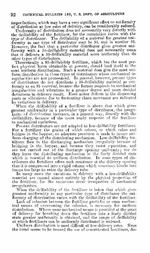
92 TECHNICAL BULLETIN 182, U. S. DEPT. OF AGBIOÜLTUBB
imperfections, which may have a very significant effect on uniformity of distribution at low rates of delivery, can be considerably reduced.
Uniformity of distribution does not necessarily vary directly with the drillability of the fertilizer, for the correlation varies with the type of distributor. The drillability of a material for greatest uni- formity in one type of distributor may be 55, and in another 95. However, the fact that a particular distributor gives greatest uni- formity with a o5-drillability material does not necessarily mean that it delivers a 55-drillability material more uniformly than do other types of distributors.
Theoretically a 95-drillability fertilizer, which has the most per- fect physical form obtainable at present, should lend itself to the most uniform distribution. Such a material does give the most uni- form distribution in those types of distributors where mechanical ir- regularities are not pronounced. In general, however, present types of distributors do not distribute a 95-drillability material as uni- formly as an 85 material, because the former responds to mechanical irregularities and vibrations to a greater degree and more decided deviations in delivery result. Even minor defects in the dispensing parts or vibrations due to fluctuating chain movement are indicated by variations in delivery.
When the drillability of a fertilizer is above that which gives greatest uniformity in a particular type of distributor, the irregu- larity of distribution increases, in a general way, directly with the drillability, because of the more ready response of the fertilizer to mechanical variations.
Present distributors are not adapted to low-drillability fertilizers. For a fertilizer the grains of which cohere, or which cakes and bridges in the hopper, no adequate provision is made to insure uni- form charging of the distributing mechanism. Low-drillability fer- tilizers flow to the discharging mechanism irregularly because of bridging in the hopper, and because they resist sefiaration, and are not carried out of the discharge opening uniformly; nor do thev leave the distributing mechanism in the finely divided state which is essential to uniform distribution. In some types of dis- tributors the fertilizer offers such resistance at the delivery opening that it is compressed into a rigid column which sometimes breaks into lumps too large to enter the delivery tube.
In many cases the variations in delivery with a low-drillability material are caused almost entirely by the physical properties of the fertilizer, for the variations occur irrespective of mechanical irregularities.
When the drillability of the fertilizer is below that which gives greatest imiformity in any particular type of distribtitor the uni- formity of distribution varies with the drillability of the fertilizer.
Lack of cohesion between the fertilizer particles or some mechan- ical means of overcoming the cohesion, is necessary for uniform distribution. Where some mechanical means is provided at the point of delivery for breaking doAvn the fertilizer into a finely divided state greater uniformity is obtained, and the range of drillability at which fertilizers can be uniformly distributed is widened.
Uniform distribution is most difficult at low-delivery rates. Since the trend seems to be toward the use of concentrated fertilizers, dis-
MECHANICAL APPLICATION OF FERTILIZERS 93
tribution at low-delivery rates demands careful consideration. In this connection mechanical precision of the distributor and proper state of subdivision of the fertilizer at the point of delivery are of major importance.
In further development of fertilizer distributors the following are some of the points that should receive consideration: Low ampli- tude of cycles or impulses of delivery ; minimum effect of head and of inclination of distributor on delivery rate; elimination of gravita- tional flow of fertilizer through the distributing mechanism; posi- tive delivery action; subdivision of fertilizer at the point of de- livery; accuracy and refinement of dispensing parts; a reference scale on the quantity-adjustment device; provision for compara- tively small changes in delivery rate ; provision for ready determina- tion of actual delivery rates; ease of emptying and cleaning; pro- tection of the mechanism from rust and corrosion; and protection of the operator from dust.
CONCLUSIONS
Drillability of fertilizers and the construction and operation of fertilizer distributors were studied under controlled conditions. The principal conclusions to be drawn from these experiments may be summarized as follows :
Drillability of fertilizers is profoundly affected by changes in the relative humidity of the atmosphere in which they are stored, and only slightly by differences in temperature. Drillability is not necessarily affected by changes in absolute humidity. The effects of rehitive humidity and temperature operate through the moisture content of the fertilizer and their extent depends upon the hygro- scopicity of the fertilizer.
All fertilizers tested are drillable at relative humidities below 50 per cent, but no fertilizer remains drillable when exposed to a hu- midity above its hygroscopic point.
Fertilizers containing a considerable proportion of material finer than 200 mesh are unduly dusty when dry and when slightly damp are undrillable in most distributors.
Fertilizers containing not less than 90 per cent of material between 5 and 80 mesh in size usually are drillable at all humidities 5 per cent or more below their hygroscopic points.
When a mixed fertilizer is heterogeneous with respect to the size, shape, or specific gravity of the particles of its components, the ma- terials separate more or less during distribution, and the ratio of the plant-food elements delivered may change markedly from time to time.
The drillability of a fertilizer varies inversely with the kmetic angle of repose. Fertilizers with a kinetic angle of repose greater than 55° usually are undrillable.
Fertilizers with an angle of repose of about 40° and composed of 20-mesh rounded grains with rough surfaces are best adapted to present types of distributors. .
Distributors deliver by volume rather than by weight ; hence their delivery rate by weight varies with the apparent specific gravity of the fertilizer.

94 TECHNICAL BULLETIN 182, U. S, DEPT. OF AGEICULTUKE
Delivery rate from bottom-delivery machines also varies greatly with changes in drillability of the fertilizer, changes in depth of the material in the hopper, and differences in the inclmation of the dis- tributor. The amount of low-drillability fertilizer discharged de- pends to a great extent upon the amount of positive action of the mechanism. Variations in delivery rate due to changes of head are greatest when the depth of material is low. Tilting a distributor toward the discharge opening increases delivery rate, and vice versa.
Delivery rate by volume does not vary in top-delivery distributors. The uniformity of distribution vanes with the design and me-
chanical refinement of the distributor and with the drillability of the fertilizer. Cycles and impulses of dehvery are the principal causes of the irregular distribution of free-flowing fertilizer. Fertilizers of low drillability are delivered unevenly by all types of distributors.
LITERATURE CITED (1) ANONYMOUS.
1838-30. MACHINE FOK SOWING LIME. Cultivator 5: 59. (2) •
1848. SEYMCUE'S MACHINE. Cultivator (n. s.) 5:190, illus. (3)
1879. IMPKOVEI) FARM MACHINERY—V. Country Gent. 44:2, illus. (4) ADAMS, J. R., and MERZ, A. R.
1929. THE HYGKOSCOPICITY 01'' FERTILIZER MATERIALS AND MIXTURES. Indus, and Engin. Chem. 21: 305-307, illus.
(5) ALLEN, ,T. T. 1879-86. ALLEN'S DIGEST OF SEEDING MACHINES AND IMPLEMENTS PATENTED
IN THE UNITED STATES ... I. 1800-79:1-1326, illus.; II. 1879-82:1327-1728; III. 1882-85:1729-2295. Washing- ton, D. G.
(6) CHRISTENSEN, A., HANSEN, A., and STOUB.EK, P. 1929. ABBEjnSI>B0VB MED KUNSTG0DNINOS8PREDERB . . . DaUSke Stat-
ens Redskabspröver Beret. 56, 96 p. (7) COUPAN, G.
1915. MACHINES DE CULTURE, PRéPARATION DES TERRES ÉPANDAGE DES ENGRAIS ET DES SEMENCES ENTRETIEN DES CULTURES. Ed. 2, 480 p., illus. Paris.
(8) FISCHER, G. 1923. DÜNGEP.sTREUMAscHiNEN. Ztschr. Pflanzenemähr. u. Düngung
(B) 2: 92-97. (9) and HAGMANN.
1921. PRÜFUNG VON KALKSTICKSTOFF-STREUMASCHINEN. PREISAUSCHREI- BEN DKs DÜNGEKSTICKSTOFF-AUSCHUSSES. Mltt. Deut. Landw.
Gesell. 36: 351-358. (10) GRAESER, K.
1924. DtJNGBBSTRBUMASCHiNEN. Ztschr. Pflauzenemähr. u. Düngung (B) 3: 111-113.
(11) GUNNESS, C. I. 1928. CONCENTRATED FERTILIZER DISTRIBUTOR. Amer. Fertilizer 69 (6) :
35, illus. (12) HuRD, W. D.
1919-20. THE NEED OF FERTILIZER DISTRIBUTING MACHINERY. PotatO Mag. 2 (10) : 16.
(13) J., A. C. 1856. CORN ctiLTURE AND BLLLiNGs' PLANTER. Country Gent. 7: 202.
(14) KÜHNE, G., and MEYER, E. 1923. LEITFADEN DER LANDWIBTSCHAJTLICHEN MAOHINENKUNDE. 122 p.,
illus. Berlin. (15) McGiNNis, L. H.
1876. THE TRUE THEORY OB' FARMING.—XI. FINENESS AND THOE0ÜGH Dia- SEMINATION OF ALL MANURES NECESSARY FOB THE BEST BESULTS. Amer. Farmer (n. s.) 5: 212-214.

MECHANICAL APPLICATION OF FEETILIZERS 95
(16) MALDEN, W. J. 1896. FARM BUILDINGS AND ECONOMICAL AGEICULTUBAL APPLIANCES 192 P.,
lllus. London. (17) MEBTENS, W.
1927. PKÜFSTANDVEBSUCHE AN DÜNGEBSTBEUMASCHINEN. Technik LandW, 8 (2) : 28-31, lllus.
(18) Ross, W. H., MEHKING, A. L., and MEEZ. A. R. 1927. HECENT DEVELOPMENTS IN THE PREPARATION AND USE OF CONCEN-
TRATED FERTiLizEats. ludus. and Engin. Chem. 19: 211-214. (19) SHAXBY, J. H., and EVANS, J. C.
1923-24. ON THE PROPERTIES OF POWDERS : THE VARIATION OF PRESSURE WITH DEPTH IN COLUMNS OF POWDERS. Faraday Soc. Trans. 19: 60-72, lUus.
(20) STORZ, H. 1928. üBER DIE ANWENDUNO VON MASCHINEN IN LANDWIRTSCHAFTLICHEN
BETRIEB. Landbau u. Technic 4 (1) : 7-8, lllus. (21) TRUOG, E., and JENSEN, O. P., compilers.
1928. REPORTS AND PROCEEDINGS OF THE JOINT COMMITTEE ON FERTILIZER APPLICATION 1025-1928. 55 p., lUus. Washington, D. C.
(22) WHITE, R., JR. 1848. DESCRIPTION OR A DRILL BARROW, FOR PLANTING SEEDS, AND APPLYING
MANURES, SUCH AS POUDRETTE. BONE-DUST, ASHES, PLASTER, MARL, ETC., AT THE SAME TIME. Cultlvator (n. S.) 5: 184r-185, lllus.

ORGANIZATION OF THE UNITED STATES DEPARTMENT OF AGRICULTURE
April 18, 1930
Secretary of Agriculture ABTHUB M. HYDE.
Assistant Secretary R- W. DONLAP.
Director of Scientific Work A. F. WOODS.
Director of Regulatory Work WALTER G. CAMPBELL.
Director of Extension Work C. W. WARBUBTON.
Director of Personnel and Business Adtninis- W. W. STOCKBEBGBE.
tration. Director of Information M. S. EISENHOWER.
Solicitor E- L. MARSHALL.
Weather Bureau CHARLES F. MARVIN. Chief. Bureau of Animal Industry JOHN R. MOHLEB, Chief. Bureau of Dairy Industry O. B. REED, Chief. Bureau of Plant Industry WILLIAM A. TAYLOR, Chief. Forest Service R- T- STUART, Chief. Bureau of Chemistry and Soils H. G. KNIGHT, Chief. Bureau of Entomology C. L. MARLATT, Chief. Bureau of Biological Survey PAUL G. EEDINGTON, Chief. Bureau of Public Roads THOMAS H. MACDONALD, Chief. Bureau of Agricultural Economics NILS A. OLSEN, Chief. Bureau of Home Economies LOUISE STANLEY, Chief. Plant Quarantine and Control Administration- LEE A. STRONG, Chief. Grain Futures Administration J. W. T. DUVEL, Chief. Food, Drug, and Insecticide Administration WALTER G. CAMPBELL, Director of
Regulatory Work, in Charge. Office of Experiment Stations , Chief. Office of Cooperative Extension Work C. B. SMITH, Chief. LUyrary CLARIBEL R. BAENETT, Librarian.
This bulletin is a joint contribution from
Bureau of Chemistry and Soils H. G. KNIGHT, Chief. Fertilizer and Fixed Nitrogen Investiga- P. G. COTTRELL, Chief,
tions. Bureau of Public Roads. THOMAS H. MACDONALD, Chief.
Division of Agricultural Engineering S. H. MCCEORY, Chief.
96
U. S. 60VERNMENT fRINTINQ OFFICE; 1010
For flale by the Superintendent of Documents, Washington, D. C. - - - Price, 30 cents
Related Documents