I Sudan University of Science and Technology Collage of Engineering Aeronautical Engineering Department FACTORS AFFECTING CIVIL AIRCRAFT AVAILABILITY A thesis submitted to Sudan University of science and technology in partial fulfillment of the requirements for the degree of B.Sc. (honor) in aeronautical engineering (propulsion and airframe) Prepared by: Abdulgader Bashir Babeker Abdulgader Omer Mohammed Abdulraheem Ebishi Saifeldeen Yagoub Abdulazeez Mohammed Tarig Saleh Elzaky Ibrahim Supervised by: Brig. General Engineer: Abdelraheem saad omer Oct 2015

Welcome message from author
This document is posted to help you gain knowledge. Please leave a comment to let me know what you think about it! Share it to your friends and learn new things together.
Transcript

I
Sudan University of Science and Technology
Collage of Engineering
Aeronautical Engineering Department
FACTORS AFFECTING CIVIL AIRCRAFT AVAILABILITY
A thesis submitted to Sudan University of science and technology in partial fulfillment of
the requirements for the degree of B.Sc. (honor) in aeronautical engineering (propulsion
and airframe)
Prepared by:
Abdulgader Bashir Babeker Abdulgader
Omer Mohammed Abdulraheem Ebishi
Saifeldeen Yagoub Abdulazeez Mohammed
Tarig Saleh Elzaky Ibrahim
Supervised by:
Brig. General Engineer: Abdelraheem saad omer
Oct 2015

II
سم هللا الرحمن الرحيم
وا من حولك فاعف { ا غليظ القلب النفض لنت لهم ولو كنت فظه ن هللاه فبما رحمة م
يحب عنهم واستغفر لهم وشاورهم في ال ننل هللاه علا هللاه مر فذاا عممت فتوكل
لين } المتوك
(519)آ عمران

III
Abstract
Availability is the measure of the degree of fitness of an aircraft round the clock to perform its
mission. Factors affecting aircraft availability must be carefully understood and monitored in
order to obtain highest possible availability level.
The most influencing factors are: reliability, maintainability, maintenance types and factors
influencing them, reparability, choice and contract, TQM, management, and aviation safety.
We conclude that availability factors, if applied, will lead to higher aircraft availability.
And recommend continue development and modification to enhance availability in the future.

IV
Dedication
It is our genuine gratefulness and warmest regard that we
dedicate this work to our parents, friends, and of course
ourselves.

V
Acknowledgement
First and foremost, praises and thanks to ALLAH, the Almighty, for
being our strength and guide to complete the thesis successfully.
We would like to express our deep and sincere gratitude to prof.
Abduraheem Saad Omer, our supervisor, for his patient, guidance,
encouragement and support.
VI
Contents
1 Chapter One: Introduction ...................................................................................................... 1
1.1 Overview .......................................................................................................................... 2
1.2 Problem statement ............................................................................................................ 2
1.3 Objectives ......................................................................................................................... 2
1.4 Approaches ....................................................................................................................... 2
2 Chapter Two: Civil aircraft types and measurement of availability ....................................... 3
2.1 Civil Aircraft types ........................................................................................................... 4
2.2 Measurement of availability ............................................................................................. 5
3 Chapter Three: Factors Influencing Availability .................................................................... 7
3.1 Introduction ...................................................................................................................... 8
3.2 Reliability ......................................................................................................................... 8
1.2.5 Definition .................................................................................................................. 8
1.2.2 Need .......................................................................................................................... 8
3.2.3 Achievement ............................................................................................................. 9
3.2.4 Achievement by Modification .................................................................................. 9
1.2.1 Results ....................................................................................................................... 9
3.3 Maintainability ............................................................................................................... 10
3.3.1 Definition ................................................................................................................ 10
3.3.2 Need ........................................................................................................................ 10
3.3.3 Achievement ........................................................................................................... 10
3.3.4 Results ..................................................................................................................... 11
3.4 Maintenance ................................................................................................................... 11
1.4.5 Definition ................................................................................................................ 11
1.4.2 Need ........................................................................................................................ 11

VII
3.4.3 Types of Maintenance ............................................................................................. 11
3.4.4 Aircraft maintenance philosophy ............................................................................ 12
3.4.5 Interchangeability ................................................................................................... 14
3.4.6 Reliability centered maintenance ............................................................................ 14
1.4.3 On board maintenance systems ............................................................................... 14
3.4.8 Maintenance of software ......................................................................................... 15
1.4.9 MSG-3..................................................................................................................... 16
3.4.10 Helicopter maintenance program ............................................................................ 16
3.4.11 Stock control of spare parts..................................................................................... 17
3.5 Reparability .................................................................................................................... 19
1.1.5 Definition ................................................................................................................ 19
1.12. Need ........................................................................................................................ 19
1.1.1 Achievement ........................................................................................................... 19
1.3 Choice and contract ........................................................................................................ 19
1.3.5 Choice ..................................................................................................................... 19
3.6.2 Contracts ................................................................................................................. 20
3.7 T.Q.M (Total Quality Management) .............................................................................. 21
3.8 Management ................................................................................................................... 21
3.9 Work study ..................................................................................................................... 21
3.10 Human factors............................................................................................................. 22
3.11 Aviation safety ............................................................................................................ 23
4 Chapter Four: Case Study of Availability for Boeing 737 and Airbus 320 .......................... 24
4.1 Aim ................................................................................................................................. 25
4.2 Method of analysis ......................................................................................................... 25
4.2.1 Key defects in twelve weeks for Boeing 737- with down time .............................. 25

VIII
4.2.2 Key defects in twelve weeks for Airbus 320 with down time ................................ 33
5 Chapter Five: Results and Conclusion .................................................................................. 40
5.1 Result .............................................................................................................................. 41
5.2 Conclusion ...................................................................................................................... 41
6 Chapter Six: Recommendations ............................................................................................ 42

1
1 Chapter One: Introduction

2
1.1 Overview
This thesis will examine, evaluate and discuss the most important influences on availability in
order to find the most efficient way to use resources to aid the achievement of high availability.
Aircraft availability level internationally depends on the environment of the operation of defined
airline in deferent countries.
Availability can be defined as the proportion of the total time for which the aircraft is fit for use.
1.2 Problem statement
Availability of civil aircraft depends on different factors such as: reliability, maintainability,
maintenance, stock control, human factors, reparability, choice and contract, management and
last but not the least is the application of the TQM (total quality management) with all its
principles.
These factors interact with each others to enhance the Aircraft availability.
If these factors are not all applied the availability will decrease.
1.3 Objectives
To find the defect of each factors.
How to solve these procedures.
To find unseen problems to increase availability of Aircraft.
1.4 Approaches
To study all the factors and how to be enhance.
To study a case study of A320 (European origin) and B737 (American origin) and
collecting data and comparing them.

3
2 Chapter Two: Civil aircraft types and measurement of
availability

4
2.1 Civil Aircraft types
Figure 1 - Civil Aircraft types

5
2.2 Measurement of availability
When availability is used as an aircraft performance parameter it is usually assumed that an
aircraft's time is shared between activities of flying, being worked on and sitting fully rectified
and ready to go.
It the measure of the degree to which an item is in the operable and committable state at the start
of the mission, when the mission is called for at an unknown (random) point in time.
There are several definitions of availability but all agree it is the ratio of some so called ''good''
time (in which the equipment is operating or ready to be operated) to a total time and it is there
for some measure of the efficiency. They differ in classifying total time. Some define it as the
operating time plus the active repair time. Some as the operating time plus the total down time
while the others define it as total calendar time.
So availability can be measure as:
Intrinsic availability =
………Equation 2.1 Ref. (1)
Operational availability
….Equation 2.2 Ref. (1)
Use availability
….Equation 2.3 Ref. (1)
Steady state availability is the inherent availability and depend on aircraft design, considering
only the inherent features of the system, but excludes such things as preventer maintenance,
logistics and administrative time.
A
……………………………………..Equation 2.4 Ref. (3)
Where:
µ= exponential repair rate
ʎ =exponential failure rate

6
To take an overall view considering maintenance, reliability, logistics, administrative and quality
control procedures 6time, it is measure as:
……………………………………………..Equation 2.5
Where:
MUT = mean up time
MDT = mean down time
A0 = operational availability = probability that a system is fit for service whether it is use for or
not.
A0 always < A1 as A1 is ideal case.
Availability normally calculated as:
…………………………..Equation 2.6
Down time in time in this equation is purely due to defect rectification work and the aircraft is
ready to fly as soon as rectification is complete, or scheduled work and flight servicing takes
within the time of rectification.
Areal measure is considered schooled work and flight servicing carried on after rectification
period complete.
Total measure daily availability we consider total time as 24 hrs. And the equation will be:
A
………Equation 2.7
Time available to fly scaled down by 6/7 to yield actual flying time. This factor considers the
length of time an aircraft signed out on a flight servicing certificate and actual flight time
recorded which showed that for every seventy minutes an aircraft was signed out, it flew for one
hour
To consider non defect work continued after defect rectification
Availability
100% …Equation 2.8

7
3 Chapter Three: Factors Influencing Availability

8
3.1 Introduction
Factors influencing civil aircraft availability are numerous, varying in the importance.
Availability as a measure of readiness and air-superiority is influenced by down time and
turnaround time down time and turnaround time are functions of aircraft reliability,
maintainability, and maintenance.
Aircraft choice, contract, besides applying TQM and management principles are also of great
importance in dictating availability level.
This chapter will discuss these factors according to their needs, achievements, results obtained
and problems to be solved in the near future to enhance availability.
3.2 Reliability
3.2.1 Definition
Reliability is the term used to describe item's ability to keep operating; it is formally defined as
the probability that an item will perform a required function, underspecified conditions, without
failure for a specified period of time. Reliability is of two kinds:
Inherent and in service. Inherent reliability achieved as a result of the basic design
considerations. In service reliability could either be improved by modification or altering
maintenance procedure. Reliability depends on operating conditions and the time span
considered 2
3.2.2 Need
The prime aim of civil aircraft procurement must be to reach the destinations on time, safely, at
the lowest possible cost.
Reliability contributes to high availability, and
To show the effect of reliability on utilization, reliability can be measured by the rate of
unscheduled maintenance arising per 1000 flying hours, which is known as the defect rate. Fig.
(2) Shows the way in which utilization varies with defect rate for a particular training aircraft. If
the aim is to fly this aircraft for 300 hours a year, a defect rate no worse than 400 per 1000 flying
hours must be achieved. An increase in the defect rate by 25% to 500 defects/1000 flying hours
would reduce the utilization to 272 hours. This is 9% reduction in utilization.

9
3.2.3 Achievement
An acceptable standard of reliability will not be achieved at an economic cost unless reliability is
given full consider during design. It must be designed into each component of an aircraft right
from the beginning and imply more involvement at all levels from the civil aviation authority
right down to the smallest subcontractor. This will cost more initially, but will pay dividends in
the future. An aircraft's expectancy of life has a direct relationship to reliability, this need to be
stated accurately in the specification. The specification must be enforced at the design stage
through a realistic research and development including a period of correct environmental testing.
Thus the best way of achieving a reasonable reliability with the lowest cost is always found by
directing efforts into the initial design phase of the aircraft, as the relative costs of rectifying a
defect in aircraft in service is about 1000 times the level of the cost during initial design. Inherent
reliability could be achieved by using well-proven components, simplicity, high quality control
of the manufacturer, together with high Skill, experienced and highly motivated of its personnel.
Continuous feedback of failure data for existing components from the responsible department to
the manufacturer, of civil aviation authority, together with the correct installation design of
equipment, also affects the reliability of aircraft in its initial stage of design.
3.2.4 Achievement by Modification
The usual way to improve reliability of an in service aircraft is to either alters maintenance
procedures or to modify components.
3.2.5 Results
The aim of civil aircraft may be to achieve a reliability which leads to a minimum total life cost
even though this entails a first cost which can be significantly higher. Higher initial cost offset
lower maintenance and spare cost.
For new projects where a project definition phase is included in the development program , the
contractor would during this phase assess the figures set in the initial requirements, in the light of
cost and time scale and include in his project study proposals for trade-offs between cost,
reliability, maintainability and time scale .

10
3.3 Maintainability
3.3.1 Definition
A characteristic of design and installation which is expressed as the probability that an item will
be retained in or restored to a specified condition within a given period of time, when the
maintenance is performed in accordance with prescribed procedures and resources.
Maintainability is often measured in term of mean time to repair (MTTR) after failure.
As availability
so maintainability affects availability. - See Equation 2.4
3.3.2 Need
Some short comings on reliability are unavoidable; when these are recognized by a designer,
they must be trade off against good maintainability.
Adequate provision must be made for access and working room to ease task of airmen carrying
out maintenance at any time and during any climatic condition 2
3.3.3 Achievement
Mean time to repair is a matter of having spare parts available, providing ready access to the
working area, having trained technicians and diagnostic equipment and tools 2
Access is provided for inspection and replacement. By having accessibility and using modular
system, maintenance effect and cost is decreased. Down time is also decreased and thus
enhancing availability 2
A large proportion of maintenance cost is caused by poor defect diagnosis. Automatic test
equipment can filter equipment close to the flight line, so that unnecessary overhauls are
avoided. Although it is expensive it reduces down time to minimum.
In forward operational areas a rapid turn-around is required with minimum support, But as much
indication as possible of fault location. Built-in test equipment (B.I.T.E.) is available in all
sophisticated avionics equipment in present aircraft. Failure can be stored in the central
maintenance panel for interrogation on landing.
The ability to diagnose the defects round during a flight and to radio forward a report would be
of great advantage. This would reduce the time spent on ground rectifying faults. The fault

11
correction stage could be started on the ground and the necessary facilities and spares would be
available prior to the landing of the aircraft 2
By using diagnostic manuals carried by air-crew in flight and ground-crew, defect could be
signaled to the base where all facilities will be ready to rectify aircraft immediately when it lands
and so down time could be reduced to minimum
Fig. (3) Shows how to plan for maintainability
3.3.4 Results
Improved maintainability decreases maintenance hours per flight hour and result in less down
time and more availability.
High reliability leads to complexity and less maintainability. The tradeoff exists between the two
concepts. The aim is t to cut down and turn round time to minimum to achieve high availability.
3.4 Maintenance
3.4.1 Definition
Maintenance is all action Necessary for retaining an item in or restoring it to a specified
condition. It is closely linked with reliability and has to be taken in to account at the design stage.
3.4.2 Need
The Purposes of maintenance is to prevent a device or component from failing or to repair
normal equipment degradation experienced with the operation of the device to keep it in proper
working order. Also maintenance procedure is used to preserve safety and reliability
characteristics inherent in the design of an aircraft and to keep it at a high level of availability
throughout its specified life.
3.4.3 Types of Maintenance
1. Preventive maintenance
All actions carried out on planned, periodic, and specific schedule to keep an item or equipment
in stated working condition through the process of checking and reconditioning these actions are
precautionary steps undertaken to forestall or lower the probability of failures or an unacceptable
level of degradation in later service, rather than correcting them after they occur.

12
2. Corrective maintenance
The unscheduled maintenance or repair to return items or equipment to a defined state and
carried out because maintenance person or users perceived deficiencies or failures.
3. Predictive maintenance
The use of modern measurements and signal processing methods to accurately diagnose item or
equipment condition during operation.
3.4.4 Aircraft maintenance philosophy
In aircraft we perform maintenance according, to the specified aircraft maintenance program, this
maintenance program specifies all the maintenance tasks and periodicity that we need to comply
in order to maintain the aircraft safety. But all maintenance tasks are developed according to
some industry standard and they all obey to basic maintenance philosophies.
In aircraft maintenance we can clearly identify three deferent philosophy types when we work
with maintenance. When you have equipment or a component you will need to specify one of
these maintenance philosophies in the follow up of the aircraft health. (see appendix I) The three
main maintenance philosophies are:
1. Hard time
Hard time, this is the first type of maintenance philosophy used since the beginning of the
aircraft industry. Hard time maintenance defines has component part has a limited time of
operation without failure. After this controlled time the component/part must be removed from
aircraft. After removal the component or part must be repaired, overhauled or discard, depending
of the component. This type of maintenance was used before Second World War for the entire
aircraft. After some hours of operation (300h, 500h) the aircraft' enters for maintenance and all
components were removed and replaced by new of overhauled components: this is Hard Time!!
During and after the Second World War with the rise of larger aircraft, replacements of all
components impractical of the high costs and time and maintenance policies were adopted.
The hard time philosophy is still used for modern aircraft components, certainly you know
several components and aircraft parts that use the hard time as maintenance policy. A lot of
component or parts are following by flight hours, cycles or calendar time and the target of
controlling the Life of component is because they have the hard time maintenance philosophy.
When they reach the limit time defined in the aircraft maintenance program, components must be
removed from the aircraft and be replaced by anew or overhauled component. An overhauled

13
component is a component that after been removed from the aircraft is checked, repaired, parts
replaced and tested in order to be reinstalled in the aircraft as a component capable to work with
no failure during the time specified in the hard time philosophy. Time since overhaul (TSO) and
time since new (TSN) are times that control the life of components when they are followed by
hard time. Fig.(4)
2. On condition
On condition, this philosophy is an evolution of hard time. During the second world war, because
of maintenance improvement requirements, by reducing costs and time in maintenance checks, it
was found that is some components and parts, it was very easy to predict component failure with
high probability of success.
Introducing simple functional tasks in the aircraft maintenance we were able to predict the
probability of component failure, by analyzing functional parameters.
If these parameters begin to present abnormal values, this was indication that component failure
is imminent and a corrective action has to be taken. This is the one condition philosophy. this
philosophy is like the medical checkup that we do every year, we perform simple exams just to
check if everything is ok. But if something is wrong the doctor can give us a treatment to avoid
the failure or the disease of the body. The on condition philosophy is the one that we can apply to
human body, hard time philosophy is imposable to apply as a preventive maintenance task.
Replacement of the heart or other organs every forty years is impractical to apply to the human
body . the on condition is just that periodic checks applied to the components to evaluate the
health and predict with high probability of success a possible failure.
The component is removed from the aircraft if we suspect that a probable failure can occur and
replaced by a new or overhauled component. Fig(5)
3. Condition monitoring
Condition monitoring, this philosophy was the last one that appear in the aircraft maintenance
development. We have the hard time, on condition and finally the condition monitoring.
The condition monitoring is not the same as on condition, sometimes the two can be confused
and problems, mistakes and safety issues can arrives.

14
Condition monitoring is not a preventive maintenance, in this philosophy the component can
fails in service, component can fails and after failure the component is replaced.
This philosophy can not be applied to equipment that affect safety or that failure can have a
significant economic impact. This is the philosophy that aircraft reliability programs are based on
the components are followed by reliability programs, that after analysis of reliability data we can
defined or change maintenance tasks in order to increase equipment reliability, reducing costs
and increasing aircraft availability.
This is the target of condition monitoring or reliability programs: controlling and analyzing
equipment time to failure and failure types in order to define improvements to the aircraft
maintenance program, increasing aircraft availability and reducing maintenance and operational
costs. Fig.(6)
3.4.5 Interchangeability
Interchangeability is a basic characteristic of good maintenance design. During maintenance
work, maximum operational availability of an aircraft at a forward base is dependent upon
minimum down time relative to its degree of interchangeability of its components.
3.4.6 Reliability centered maintenance
Reliability centered maintenance is a disciplined procedure to return an
Aircraft to its originally designed safe and reliable condition with minimum maintenance cost by
elimination of all unnecessary checking and inspection practice. It includes, "Hard Time Limits",
"On Condition. Inspection" and "Condition monitoring". The success of reliability centered
maintenance in the airline industry led to its application in military aircraft maintenance practice.
It is a viable. Alternative to increasing maintenance cost, down time low and availability of
aircraft
3.4.7 On board maintenance systems
Onboard maintenance systems are the latest development in aircraft avionics. They began with
simple press to test buttons and failure flags fitted to individual items in the cockpit. These
required human action and recorded no data. Autopilot systems were the driving force behind
development of a better maintenance system to embrace all of the autopilots functions and its
components, with the intention of meeting the integrity and certification requirements of auto

15
land. They very high safety level specified for auto land could only be attained using redundancy
in a system this implied self-test and reporting to establish the system was function correctly. In
the early analogue electronic auto land systems this remained part of the components. But the
introduction airborne digital computers made it possible to use a central computer for monitoring
and display of system performance.
A dedicated system control the display unit ( MCDP ). Was fitted on Boeing 757and
767aircraft, which entered service in the early 1980s. The similar function on Boeing
737 aircraft was automated using the control and display units ( CPU ) of the
performance data computer ( PDC ) for the 737-200 series, and the flight management
computer ( FMC) of the 737-300 series aircraft.
The Boeing 757 and 767 also introduced the engine indicated and crew alerting system (EICAS)-
pat of the glass cockpit as its popularly known. This is a maintenance-significant system, with
maintenance data display for engines. APU electrical, hydraulic and environmental control
systems. In addition dispatch critical maintenance data are displayed in the form of status
messages as part of the caution and warning function.
The Boeing 747-400 central maintenance computer (CMC) system evolved the 757/767 EICAS
and MCDP. The CMC connects to must aircraft systems which use electronics. One of its
primary functions is to relate these system- fault signals with observable. Flight deck effects such
as EICAS caution, warning and status messages display flags, or other visual/aural indications.
3.4.8 Maintenance of software
Many modern aircraft systems use digital electronics for signaling and control. The instructions
for these functions may be hard-wired as logic circuits, embedded in programmable devices, or
stored in removable magnetic media for use in volatile memory when needed. This is 'software'
even if the aircraft stores it in hardware for safety purposes. Since the manufacturer may have
written the instructions on a development system. Storage such as magnetic disk or tape is too
delicate for safe use on aircraft, so read-only memories are used; examples are navigation
system, radar signal processor, engine controls and flight management computers.
The operator who uses digital avionics may encounter defects in the component or system that
result from hardware failures or from software faults. That means that development of the
software needs to be managed. In addition to hardware maintenance as practiced with non-digital
equipment. It is not usual for operators to have authority to modify their own software,

16
particularly in systems critical for flight safety. The operator is therefore dependent on the
equipment supplier for diagnosis and correction of software faults.
3.4.9 MSG-3
Maintenance Steering Group, Operator/Manufacturer Scheduled Maintenance Development is a
document developed by the Airlines For America (A4A) and it aims to present a methodology to
be used for developing scheduled maintenance tasks and intervals, which will be acceptable to
the regulatory authorities, the operators and the manufacturers. The main idea behind this
concept is to recognize the inherent reliability of aircraft systems and components, avoid
unnecessary maintenance tasks and achieve increased efficiency2
MSG-3 is widely used to develop initial maintenance requirements for modern commercial
aircraft which are published as a Maintenance Review Board Report (MRBR) and include four
main sections:
Systems and Power plant.
Aircraft Structure.
Zonal Inspections.
Lightning/High Intensity Radio Frequency.
Each section contains methodology and specific decision logic diagrams. Particularly, the
Systems and Power plant section requires the identification of Maintenance Significant Items
(MSI) before the application of logic diagrams to determine the maintenance tasks and intervals.
In addition to these tasks developed by using MSG-3 analysis, other maintenance tasks may be
identified as part of the certification process, which requires System Safety Assessment (SSA)
and use of methods such as Failure Modes and Effect Analysis (FMEA)’ (FAR/CS 1309). Such
tasks are called ‘Certification of Maintenance Requirements (CMR)’. Similarly, the “Aircraft
Structures’ section describes the Structure Significant Items (SSI), which are different than
Principal Structure Element PSE) (FAR/CS 25.571) and it also provides methods and logic
diagrams, which are to be used for the development of structural inspections tasks2
3.4.10 Helicopter maintenance program
A Health Usage Monitoring System (HUMS) records the status of critical systems and
components on helicopters so that the early detection of progressive defects, or indications of
them, is possible and thus rectification can be achieved before they have an immediate effect on
operational safety. The on-board equipment stores data on a PCMCIA Card. For analysis, the

17
card is downloaded after flight and maintenance analysis can then be performed on a ground-
based computer. These systems were first deployed in the early 1990s as a response to the
relatively poor continuing airworthiness record and their introduction led to, and continues to
support, significant improvements in both safety and reliability2
A typical HUMS system uses sensors, distributed throughout the airframe and its components,
which are linked to a central computer unit with a data recording and storage system. Monitoring
trends in the recorded data is particularly important - it allows system specialists to determine
whether the aircraft has developed (or is likely to develop) faults that require rectification2
The extent of HUMS data capture varies considerably. A basic system collects some usage
parameters such as take-offs, landings, engine starts and winch lifts as well as a small subset of
engine and transmission health data. The most modern systems monitor the health of all
significant vibrating and spinning parts - engines, gearboxes, shafts, fans, rotor systems - and
other components. The operational context of events is recorded so that the trends can be fully
analyzed and maintenance crews are thus able to proactively perform condition-based
maintenance. The latest equipment allows the data acquired to be processed onboard the aircraft
or at a ground station - and some systems allow it to be transmitted, whilst the helicopter is in
flight, via satellite communications to operator maintenance control units so that subsequent
maintenance downtime can be minimized by pre-planning. These systems can also be configured
to automatically report urgent or emergency conditions to the operator and manufacturer from
anywhere in the world2
3.4.11 Stock control of spare parts
The provision of materials and spare parts for the production process in a timely manner
appropriate quality and quantity required. The continuation of production requires as much
storage of these materials.
Spare parts types
1- Rotatable spare parts.
2- Repairable parts.
3- Recoverable spares.
4- Expendable spares.
Stock control for expendable spares
Two main questions must be answered In order to calculate spares Quantity:

18
How much to order?
When to order?
There have been a lot of operations research studies and special computer programs are
available. A basic, simple and reasonable effective procedure is to calculate economic order
quantities as follows:
There are two main costs, the cost of making an order and the cost of holding stock.
Let:
Cs: be the cost of making an order
C: the unit cost of an item
I: the cost of carrying stock as rate per cent per annum
B: the size of the buffer stock
Q: the order quantity
Y: the annual usage
The average stock is
……………………………………...Equation 3.1
The annual cost of carrying stock is (
…………..Equation 3.2
The number of orders per annum is
…………………………….Equation 3.3
The annual cost of ordering is
………………………………Equation 3.4
Total annual cost :
. + (
………………………………Equation 3.5
Differentiating CT with respect to Q and equating to zero
. +
= 0
And
Q =
………………………………………………………Equation 3.6
Q is then the quantity to order to give the minimum total cost i.e. the economic order quantity.
This equation is mainly controlling the consumable spares. Fig.(7)

19
3.5 Reparability
3.5.1 Definition
Reparability is the probability that a failed item or equipment will be restored to operability in
not more than a specified interval of active repair time when maintenance is performed under
specified conditions.
3.5.2 Need
It is used to determine the damage on aircraft item, component or structure and minimum time to
repair (MTTR) to enhance availability.
3.5.3 Achievement
Adoption of repair by replacement (modules), interchangeability and redundancy in reducing
vulnerability will involve tradeoffs against performance and weight. An extensive research and
development program is required to examine increased retirements lives, repair versus
replacement decisions, deferability criteria and quick and interim-fix capabilities to assess the
risks and benefits that will be achieved.
3.6 Choice and contract
3.6.1 Choice
The factors influencing civil aircraft choice includes economics, geography, politics and status.
Those factors and others must be carefully assessed, before the commitment of choice otherwise
aircraft availability will be seriously degraded. In order to achieve the desired level of
effectiveness a balance sheet in resources (money, manpower or material) is assessed. If the
choice of aircraft to be effective in a large number of situations, rather than highly effective in
one and of little use or ineffective in another, consideration will be given to aircraft with multi-
role capability 2The methodology for making an optimum choice begins with an examination of
the circumstances of current and possible future operation. Co-operation and participation of
experts in the fields of Politics, economics and science together could be integrated to produce a
comprehensive study in which the major policy options are exposed in cost effectiveness terms.
Advantages, disadvantages and implications of adopting each option are assessed and quantified.
It is the job of the decision maker to apply judgment to the critical areas and to decide the most

20
effective option that uses the available resources in the best possible way. When preparing for
the launch of a new aircraft, a careful and comprehensive study of the different options available
must be carried out at the project definition phase. At this stage the project should be well
enough defined to a choice possible and the cancellation of any Un-needed projects should not
result in high cancellation costs.
Choice between aircraft which have reached service is facilitated by failure rate and cost data
which has already been collected. Nevertheless the problem of collecting useful data and
carrying out an accurate analysis remains.
The assessment of modification purposes is another area in which availability is an important
consideration.
3.6.2 Contracts
When the "best" option has been chosen in the project definition phase, it is usual practice to
draw up a contract between the customer and a contractor to define the specification of that
option. Customer's specification includes inspection and quality standards, delivery requirements
and any adjustment for inflation. Contractor's specification sets out how the contractor aims to
meet the requirements of the customer. Types of contract include a fixed-price, cost plus fixed
fee and the target plus incentive contract. The target may include a final price or may also extend
to targets for weight, reliability or important aspects of performance.
Warranty, delivery data, provision of spare parts and training personnel may be included in the
contract and these factors have a great influence both on availability levels immediately after
introduction and on levels in the long o into great detail term. The contract may go into great
detail and may cover such items as the need for the aircraft to be refueled and rearmed while the
engine is running, to cut down and turnaround time to minimum and enhances availability.
During any warranty period the contractor is responsible for keeping availability of aircraft on
target within the level of support agreed. There may also be clauses providing for penalties
payable by the contractor for any default on delivery dates or on in-service reliability or running
cost targets. The difficulty of placing responsibility on the contractor or equipment supplier has
lead to well defined and clear clauses outlining responsibilities for specifications laid down in the
contract2

21
3.7 T.Q.M (Total Quality Management)
To apply T.Q.M will enhance availability as you are leading personnel rather than managing
them. Fig.(8)
3.8 Management
To apply the principles of management (POSTCORB)
P : planning O : organization ST: staffing
CO : co−ordination R : reporting B: budgeting
3.9 Work study
Work study is the systematic examination of the method of carrying out activates such as to
improve the effective use of resources and to set up standards of performance of the activates
carried out.
In simple terms work study measure work and defines some performance standards. They are
many uses for time estimate for tasks. Operations managers can guess or assumed that a job is
done in the correct time or they can be systematic and use time data gathered by systematic
technique which has reasonable accuracy.
Work study industrial engineers need time data to plan and evaluate production, transformation
processes. Rewards systems need such data for performance related bonuses .cost calculation
need to incorporate operative machines job times costing systems reference work study data
.work study data contributes to:
Improved methods to raise output, quality, reduce wastage, enhance reliability and ensure safety.
Standard time data contributes to capacity planning, scheduling, control of staff, asset utilization
and quality improvement. Services and after-sales method improvements may be obtained as
well as process improvement and better raw materials usage.
Implementation planning for product and service and process design requires a detailed
Understanding of methods and timing in a distribution and transport system we can evaluate
logistical efficiencies. Fig.(9)

22
3.10 Human factors
Human error has been documented as a primary contributor to more than 70 percent of
commercial airplane hull-loss accidents. While typically associated with flight operations, human
error has also recently become a major concern in maintenance practices and air traffic
management. Boeing human factors professionals work with engineers, pilots, and mechanics to
apply the latest knowledge about the interface between human performance and commercial
airplanes to help operators improve safety and efficiency in their daily operations.
The term "human factors" has grown increasingly popular as the commercial aviation industry
has realized that human error, rather than mechanical failure, underlies most aviation accidents
and incidents. If interpreted narrowly, human factors are often considered synonymous with crew
resource management (CRM) or maintenance resource management (MRM). However, it is
much broader in both its knowledge base and scope. Human factors involves gathering
information about human abilities, limitations, and other characteristics and applying it to tools,
machines, systems, tasks, jobs, and environments to produce safe, comfortable, and effective
human use. In aviation, human factors is dedicated to better understanding how humans can most
safely and efficiently be integrated with the technology. That understanding is then translated
into design, training, policies, or procedures to help humans perform better.
Despite rapid gains in technology, humans are ultimately responsible for ensuring the success
and safety of the aviation industry. They must continue to be knowledgeable, flexible, dedicated,
and efficient while exercising good judgment. Meanwhile, the industry continues to make major
investments in training, equipment, and systems that have long-term implications. Because
technology continues to evolve faster than the ability to predict how humans will interact with it,
the industry can no longer depend as much on experience and intuition to guide decisions related
to human performance. Instead, a sound scientific basis is necessary for assessing human
performance implications in design, training, and procedures, just as developing a new wing
requires sound aerodynamic engineering.
And What happened in the accident of aircraft of German wing company shows how importance
It is (the co-pilot was mad).

23
3.11 Aviation safety
Aviation safety Means ensuring the safety of people onboard aircraft and those over flown by the
aircraft. It is the concern of the whole international community.
Efforts to achieve safety have been united. An international convention was held in Chicago in
December 1944.
An international civil aviation organization (ICAO) has been formed to serve the goals of
signatories to the convention (known as contracting states). Elements of safety have been
identified and Obligations of contracting states have been defined. Fig.(10)
Figure 10 - Aviation Safety elements

24
4 Chapter Four: Case Study of Availability for Boeing 737 and
Airbus 320

25
4.1 Aim
The purpose of this chapter of the thesis is to calculate, compare and comment upon the overall
availability level achieved by the American Boeing 737-300 and European Airbus 320.
It is anticipated that the case study will lead to better understanding of the important factors
affecting availability, and of cost effective ways in which availability might be improved. It is
also anticipated that more general conclusion will be drown from the study which will help with
future design purchasing procurement, evaluation and modification programs.
Data source
Technical records of Sudanese aircraft companies.
4.2 Method of analysis
Identification of key defects, i.e. those responsible for the longest down times of Boeing
737 and airbus 320 within typical three months period.
Record down time due to key defects.
4.2.1 Key defects in twelve weeks for Boeing 737- with down time
Table 4-1 week 1 -B737
Equipment Defect Down time Hrs.
Landing gear MLG tire no.1 worn out of limit 1
Engine Low oil pressure 2
Hydraulic system Oil leak shock absorber 15
Landing gear NLG wheel no.2 worn out of
limit
2
20
+6hrs non-defect work

26
Table 4-2 week 2 -B737
Equipment Defect Down time Hrs.
Engine High engine R.P.M during idling 10
Avionics f/o mach airspeed indicator
replaced
1
Hydraulic system Low hydraulic pressure 8
19
+8hrs non-defect work
Table 4-3 week 3 -B737
Equipment Defect Down time Hrs.
Landing gear MLG tire no.2 worn out of limit 1
Landing gear MLG wheel no.2 worn out of
limit
2
Avionics HF has problem with
transmission
1
Engine No starting 25
29
+6hrs non-defect work
Table 4-4 week 4 -B737
Equipment Defect Down time Hrs.
Landing gear MLG tire no.1 worn out of limit 1
Avionics Main battery replaced 1
Flap actuator Flap actuator replaced 2
APU APU fire ext. bottle replaced 1
5
+10hrs non-defect work

27
Table 4-5 week 5 -B737
Equipment Defect Down time Hrs.
Engine Fuel pipes worn out 20
Landing gear MLG wheel no.2 worn out of
limit
2
Landing gear NLG wheel no.1 worn out of
limit
2
24
+6hrs non-defect work
Table 4-6 week 6-B737
Equipment Defect Down time Hrs.
Nav. Light Left position nav light u/s 1
Engine LH ignition lead replaced 1
Fule system Fuel leakage from tank 4
Landing gear Replaced NLG wheel assy no.2 2
8
+7hrs non-defect work
Table 4-7 week 7 -B737
Equipment Defect Down time Hrs.
Spoiler actuator Spoiler actuator no.4 out board 1
Engine High engine r.p.m in crusing 10
Engine Engine no.1 has been replaced 5
Landing gear Replaced MLG wheel assy no.1 2
18
+7hrs non-defect work

28
Table 4-8 week 8 -B737
Equipment Defect Down time Hrs.
Landing gear MLG wheel and tire no.4
replaced
3
Engine LH ignition lead replaced 1
Fule system Fuel leakage from tank 4
Landing gear Replaced NLG wheel assy no.2 2
Air condition Automatic flow control cabin
press. Replaced
2
12
+14hrs non-defect work
Table 4-9 week 9 -B737
Equipment Defect Down time Hrs.
Landing gear MLG tire no.1 worn out of limit 1
Engine Air intake damage. 15
Hydraulic system Low hydraulic pressure 8
Landing gear NLG wheel no.2 worn out of
limit
2
26
+6hrs non-defect work

29
Table 4-10 week 10 -B737
Equipment Defect Down time Hrs.
Fire ext. bottle Cargo compartment fire ext.
bottle replaced
1
Avionics Taxi light u/s 1
Engine CSD low oil pressur 3
APU APU refuse to start 2
7
+10hrs non-defect work
Table 4-11 week 11 -B737
Equipment Defect Down time Hrs.
Landing gear MLG tire no.2 worn out of limit 1
Brake system Auto brake dis arm after landing 1
Hydraulic system Oil leak shock absorber 15
Landing gear NLG wheel no.2 worn out of
limit
2
19
+6hrs non-defect work
Table 4-12 week 12 -B737
Equipment Defect Down time Hrs.
Landing gear MLG wheel no.1 worn out of
limit
2
Spoiler actuator Spoiler actuator no.4 out board 1
Landing gear Replaced MLG wheel assy no.2 2
Engine Engine no.2 showing high EGT 2
30
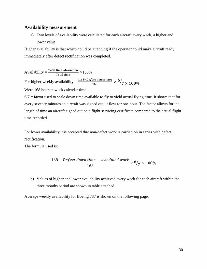
Availability measurement
a) Two levels of availability were calculated for each aircraft every week, a higher and
lower value.
Higher availability is that which could be attending if the operator could make aircraft ready
immediately after defect rectification was completed.
Availability = –
100%
For higher weekly availability =
Were 168 hours = week calendar time.
6/7 = factor used to scale down time available to fly to yield actual flying time. It shows that for
every seventy minutes an aircraft was signed out, it flew for one hour. The factor allows for the
length of time an aircraft signed out on a flight servicing certificate compared to the actual flight
time recorded.
For lower availability it is accepted that non-defect work is carried on in series with defect
rectification.
The formula used is:
b) Values of higher and lower availability achieved every week for each aircraft within the
three months period are shown in table attached.
Average weekly availability for Boeing 737 is shown on the following page.

31
Higher, lower and average availability achieved week-by-week expressed as percentage
value for BOEING737
Week 7 Week 8 Week 9 Week 10 Week 11 Week 12
LOW HIGH LOW HIGH LOW HIGH LOW HIGH LOW HIGH LOW HIGH
72.96 76.53 72.45 79.59 69.40 72.45 77.04 82.14 72.69 76.02 78.06 82.14
Week 1 Week 2 Week 3 Week 4 Week 5 Week 6
LOW HIGH LOW HIGH LOW HIGH LOW HIGH LOW HIGH LOW HIGH
75.45 75.51 71.94 76.02 67.86 70.92 78.06 83.16 70.41 73.47 78.06 81.63

32
Figure 21- Average weekly availability for Boening737

33
4.2.2 Key defects in twelve weeks for Airbus 320 with down time
Table 4-13 Week 1-A320
Equipment Defect Down time Hrs.
Landing gear MLG tire no.1 worn out of limit 1
Avionics Main battery replaced 1
APU APU fire ext. bottle replaced 1
3
+4hrs non-defect work
Table 4-14 Week 2-A320
Equipment Defect Down time Hrs.
Landing gear MLG tire no.2 worn out of limit 1
Landing gear MLG wheel no.2 worn out of
limit
2
Avionics HF has problem with
transmission
1
Fuel system Fuel pump u/s 12
16
+6hrs non-defect work
Table 4-15 Week 3-A320
Equipment Defect Down time Hrs.
Landing gear MLG tire no.1 worn out of limit 1
Engine Low oil pressure 2
Avionics VHF u/s 10
Landing gear NLG wheel no.2 worn out of
limit
2

34
15
+9hrs non-defect work
Table 4-16 Week 4-A320
Equipment Defect Down time Hrs.
Engine High engine R.P.M during idling 10
Landing gear NLG wheel no.1 worn out of
limit
2
Hydraulic system Low hydraulic pressure 8
Landing gear MLG wheel no.1 worn out of
limit
2
22
+8hrs non-defect work
Table 4-17 Week 5-A320
Equipment Defect Down time Hrs.
Landing gear MLG wheel and tire no.4
replaced
3
Hydraulic system Hydraulic leak 10
Landing gear Replaced NLG wheel assy no.2 2
Engine Low fuel pressure 2
17
+10hrs non-defect work
Table 4-18 Week 6-A320
Equipment Defect Down time Hrs.
Engine Fuel pipes worn out 20
Landing gear MLG wheel no.2 worn out of
limit
2
22
+6hrs non-defect work

35
Table 4-19 Week 7-A320
Equipment Defect Down time Hrs.
Landing gear MLG tire no.1 worn out of limit 1
Avionics VHF micselector captin side u/s 1
Fuel system Fuel leakage from tank 4
6
+8hrs non-defect work
Table 4-20 Week 8-A320
Equipment Defect Down time Hrs.
Landing gear MLG tire no.2 worn out of limit 1
Landing gear NLG wheel no.2 worn out of
limit
2
Engine Low fuel pressure 2
Landing gear NLG wheel no.1 worn out of
limit
2
APU APU cut out bleed and electrical
power
2
9
+4hrs non-defect work

36
Table 4-21 Week 9-A320
Equipment Defect Down time Hrs.
Engine RH ignition lead replaced 1
Landing gear Replaced NLG wheel assy no.2 2
Landing gear Replaced MLG wheel and tire
no.3
3
6
+7hrs non-defect work
Table 4-22 Week 10-A320
Equipment Defect Down time Hrs.
Spoiler actuator Spoiler actuator no.2 out board 1
Landing gear Replaced MLG wheel assy no.1 2
APU APU refuse to start 2
engine High engine R.P.M in crusing 10
15
+9hrs non-defect work
Table 4-23 Week 11-A320
Equipment Defect Down time Hrs.
Fire ext. bottle fire ext. bottle replaced 1
Avionics Taxi light u/s 1
Landing gear Replaced MLG wheel no.2 2
4
+5hrs non-defect work

37
Table 4-24 Week 12-A320
Equipment Defect Down time Hrs.
Landing gear MLG wheel no.1 worn out of
limit
2
Engine No starting 25
Landing gear Replaced MLG wheel assy no.2 2
FMC FMC no.2 is u/s 1
30
+8hrs non-defect work

38
Higher, lower and average availability achieved week-by-week expressed as percentage
value for AIRBUS 320
Week 1 Week 2 Week 3 Week 4 Week 5 Week 6
LOW HIGH LOW HIGH LOW HIGH LOW HIGH LOW HIGH LOW HIGH
82.14 84.18 74.50 77.55 73.47 78.06 70.41 74.49 71.94 77.04 71.43 74.49
Week 7 Week 8 Week 9 Week 10 Week 11 Week 12
LOW HIGH LOW HIGH LOW HIGH LOW HIGH LOW HIGH LOW HIGH
78.57 82.69 79.08 81.12 79.08 82.69 73.47 78.06 81.12 83.67 66.32 70.41

39
Figure 32- Average weekly availability for Airbus320

40
5 Chapter Five: Results and Conclusion

41
5.1 Result
In comparison of aircraft Boeing737 American origin and Airbus320 European origin in
airworthy availability, it is found –as in the case study- Airbus320 is more available than
Boeing737.
5.2 Conclusion
Availability factors mentioned if fulfilled well, we get high availability.
Human factors, leading personnel, and not managing them are the main factors which
enhance grate availability.

42
6 Chapter Six: Recommendations

43
Recommendations
To apply the factors specially the human factors and leadership instead of managing
them, will affect high availability. Since human being is the leader of any development
and modification.
The development and modification of aircraft design by using composite material and
plasma welding and more digital electronics will be in continuous progress of aircraft
availability although it is in initial stage
44
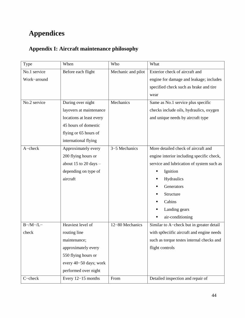
Appendices
Appendix I: Aircraft maintenance philosophy
Type When Who What
No.1 service
Work−around
Before each flight Mechanic and pilot Exterior check of aircraft and
engine for damage and leakage; includes
specified check such as brake and tire
wear
No.2 service During over night
layovers at maintenance
locations at least every
45 hours of domestic
flying or 65 hours of
international flying
Mechanics Same as No.1 service plus specific
checks include oils, hydraulics, oxygen
and unique needs by aircraft type
A−check Approximately every
200 flying hours or
about 15 to 20 days –
depending on type of
aircraft
3−5 Mechanics More detailed check of aircraft and
engine interior including specific check,
service and lubrication of system such as
Ignition
Hydraulics
Generators
Structure
Cabins
Landing gears
air-conditioning
B−/M−/L−
check
Heaviest level of
routing line
maintenance;
approximately every
550 flying hours or
every 40−50 days; work
performed over night
12−80 Mechanics Similar to A−check but in greater detail
with sp0eciific aircraft and engine needs
such as torque testes internal checks and
flight controls
C−check Every 12−15 months From Detailed inspection and repair of

45
Appendix II: Figures
Figure 2 -utilization varies with defect rate for a particular training aircraft
depending on aircraft
type; airplane out of
service for 3−5days
150−200mechanics
and inspectors –
depending on
aircraft type
aircraft, engine, components ,systems
and cabin, including operating
mechanisms, flight controls and
structure tolerances
D−check Most intensive
inspection every 4−5
years depending on
aircraft type; airplane
out of service up to 30
days
From 150−300
mechanics and
inspectors –
depending on
aircraft type
Major structure inspections for detailed
needs which include attention to fatigue
corrosion; aircraft is dismantle, repaired
and rebuild as required ; system and
parts are tested, repaired or replaced

46
Figure 3 - plan for maintainability
Figure 4 - Hard Time Maintenance

47
Figure 5 - On Condition Maintenance
Figure 6 - condition monitoring

48
Figure 7 - stock control

49
Figure 8 - TQM diagram

50
Figure 94 - work study

References
1. Rettere, B.L, Consideration of maintainability in reliability programs.
McGraw-Hill 1966.
2. T.wharton, The need for reliability in RAF Instn. Mech. Engrs. 1968.
3. Mitchell O.Locks, Reliability, Maintainability and Availability Assessment.
Hayden Book Company 1973.
4. J.P Fielding, Aircraft maintainability paper. DES7831 1978.
5. A.N Hoften, Project management paper June 1979. A.T.E. collage of
aeronautics C.I.T.
6. Chicago convention -Air Law syllabus , Aeronautical Engineering
department, Engineering collage, Sudan University of science and
technology.
7. Douglas A. Wiegmann, A Human error Approach to Aviation Accident
Analysis. Ashgate Publishing. 2003
8. T.Q.M Subject , Engineering Management syllabus, Aeronautical
Engineering department, Engineering collage, Sudan University of science
and technology.
Related Documents