RELEASED RELEASED RELEASED K-STSM-14.1.12-REVE-VPF NOVEMBER 1996 REVISION E Facility Handbook for the Vertical Processing Facility CONTRACT NAS10-11400 DRD CA-4

Welcome message from author
This document is posted to help you gain knowledge. Please leave a comment to let me know what you think about it! Share it to your friends and learn new things together.
Transcript
RELEASEDRELEASEDRELEASED
K-STSM-14.1.12-REVE-VPFNOVEMBER 1996
REVISION E
Facility Handbook for theVertical Processing Facility
CONTRACT NAS10-11400DRD CA-4

RELEASEDRELEASEDRELEASED
K-STSM-14.1.12November 1996
Revision E
RELEASEDRELEASEDRELEASED
FACILITY HANDBOOK
FOR THE
VERTICAL PROCESSING FACILITY
PREPARED BY:
/s/Jan Tiberius
Jan Tiberius, F376Senior Technical Writer, MDS&DS
APPROVED BY:
/s/Shannon D. Bartell
Shannon D. Bartell, BEActing Director, Payload Flight Systems
/s/Bobby Bruckner
Bobby G. Bruckner, BRDirector, Payload Ground Systems

RELEASEDRELEASEDRELEASED
K-STSM-14.1.12
RELEASED
i
LIST OF EFFECTIVE PAGES
Revision E supersedes revision D, dated March 1993. The total number of pages inthis publication is 61, and consists of the following:
Page No.
approval pagei thru xii1-1 through 1-42-1 through 2-83-1 through 3-144-1 through 4-125-1 through 5-46-1 through 6-6
K-STSM-14.1.12
RELEASED
ii
THIS PAGE INTENTIONALLY LEFT BLANK
K-STSM-14.1.12
RELEASED
iii
TABLE OF CONTENTS
Sec/Par Title Page
I INTRODUCTION...........................................................................1-11.1 Purpose ....................................................................................1-11.2 Scope........................................................................................1-11.3 Customer Charge......................................................................1-11.4 Facility Accommodations ..........................................................1-11.5 Emergency Planning and Community Right-to-Know ...............1-31.6 Hazardous and Controlled Waste.............................................1-3
II FACILITY DESCRIPTION.............................................................2-12.1 Location and Description ..........................................................2-12.2 VPF Functional Areas...............................................................2-32.2.1 CWAs .......................................................................................2-42.2.1.1 Air Lock.....................................................................................2-42.2.1.2 Highbay.....................................................................................2-52.2.1.3 Highbay Test Cells ...................................................................2-52.2.2 Mechanical and Electrical Support Areas.................................2-52.2.3 Operations Support...................................................................2-52.3 Security.....................................................................................2-62.4 Personnel Access .....................................................................2-72.5 Requirements and Special Considerations...............................2-7
III MECHANICAL SYSTEMS ............................................................3-13.1 Test Cell Elevation Platforms....................................................3-13.2 Material Handling Equipment....................................................3-43.2.1 Cranes ......................................................................................3-43.2.2 Test Cells Hoist ........................................................................3-53.2.3 Hydrasets..................................................................................3-53.2.4 Elevator.....................................................................................3-53.2.5 Electric Towing .........................................................................3-63.2.6 Air-Bearing Pallet......................................................................3-63.3 Compressed Air and Gases......................................................3-63.3.1 Gaseous Nitrogen.....................................................................3-63.3.2 Gaseous Helium .......................................................................3-73.3.3 Breathing Air .............................................................................3-73.3.4 Compressed Air ........................................................................3-73.4 Vacuum System........................................................................3-83.5 Heating, Ventilation and Air-Conditioning.................................3-93.6 Contamination Control and Monitoring Systems.......................3-103.6.1 Cryogenic Vent .........................................................................3-10

K-STSM-14.1.12
RELEASED
iv
TABLE OF CONTENTS (continued)
Sec/Par Title Page
3.6.2 Hypergolic Propellant Vapor Exhaust System ..........................3-103.6.3 Propellant Waste Drain System................................................3-103.7 Fire Protection Systems............................................................3-113.7.1 Fire Detection System ..............................................................3-113.7.2 Fire Alarm System ....................................................................3-113.7.3 Fire Control Equipment.............................................................3-113.7.4 Water Deluge System...............................................................3-113.7.5 Automatic Sprinkler System......................................................3-123.8 Local Environmental Control System........................................3-123.9 Safety Equipment......................................................................3-133.10 Mechanical Preparations for Payload Processing ....................3-14
IV ELECTRICAL SYSTEMS .............................................................4-14.1 Facility Power ...........................................................................4-14.1.1 Highbay Power Receptacles.....................................................4-14.1.2 Air Lock Power Receptacles.....................................................4-14.1.3 Test Cells Power Receptacles..................................................4-14.1.4 Direct Current Electrical Power.................................................4-24.1.5 Electrical Check-out Accessory Kits .........................................4-24.1.6 Illumination ...............................................................................4-24.1.7 Grounding.................................................................................4-24.1.8 Lightning Protection..................................................................4-24.2 Electronic System .....................................................................4-24.2.1 CITE/LPS..................................................................................4-34.2.2 Interface Terminal Distributor ...................................................4-34.2.3 Record and Playback Assembly ...............................................4-34.2.4 Payload/Orbiter Interfaces........................................................4-54.2.5 Aft Flight Deck Simulator ..........................................................4-64.2.6 T-0 Umbilical Support ...............................................................4-64.2.7 CITE Equipment Physical Layout .............................................4-64.2.8 Interface Test Procedures ........................................................4-104.3 Auxiliary Facility Interface Points..............................................4-104.4 Fueling/Defueling Safeguards ..................................................4-11
V COMMUNICATIONS AND DATA HANDLING..............................5-15.1 Communications .......................................................................5-15.1.1 OIS-D........................................................................................5-15.1.2 Closed-Circuit Television..........................................................5-15.1.3 Other Communications .............................................................5-2

K-STSM-14.1.12
RELEASED
v
TABLE OF CONTENTS (continued)
Sec/Par Title Page
5.2 Data Handling...........................................................................5-25.2.1 Wideband Cable Transmission System....................................5-25.2.2 Reradiating Antenna System ....................................................5-3
VI FACILITY DESCRIPTION SUMMARY..........................................6-16.1 Safety........................................................................................6-16.2 Floor Space ..............................................................................6-16.3 Ceiling Heights .........................................................................6-26.4 Equipment Entry .......................................................................6-26.5 Cranes ......................................................................................6-26.6 Hook Heights ............................................................................6-26.7 Systems and Equipment ...........................................................6-36.8 Temperature/Humidity ..............................................................6-36.9 Cleanliness Specifications........................................................6-46.10 Environmental Monitoring .........................................................6-46.11 Electrical Power ........................................................................6-46.12 Illumination ...............................................................................6-46.13 Communications .......................................................................6-56.14 Data Handling...........................................................................6-5
K-STSM-14.1.12
RELEASED
vi
LIST OF FIGURES
Figure Title Page
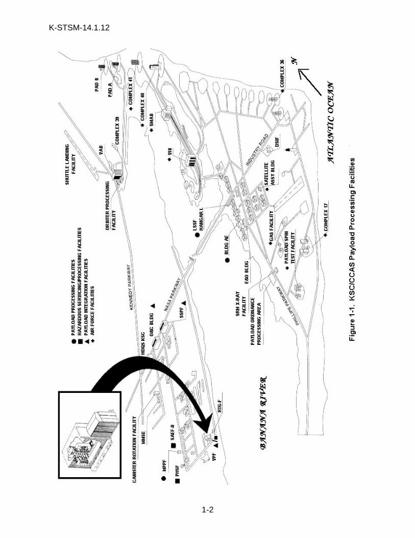
1-1 KSC/CCAS Payload Processing Facilities....................................1-22-1 Aerial Photograph of the VPF Complex ........................................2-12-2 VPF Complex Site Plan.................................................................2-22-3 OSB and Annex Floor Plan ...........................................................2-32-4 VPF Floor Plan..............................................................................2-42-5 VPF Test Cells ..............................................................................2-63-1 VPF Test Cell Elevation ................................................................3-23-2 VPF Platform Access ....................................................................3-33-3 VPF Access Platforms...................................................................3-33-4 VPF Elevating Platforms ...............................................................3-43-5 VPF Cranes - Hook Interface Dimensions ....................................3-53-6 Articulated Arm Reach Capability .................................................3-63-7 Compressed Air and Gases in VPF ..............................................3-83-8 VPF Emergency Warning/Fire Protection (Highbay) ....................3-123-9 ECS Outlets, Typical All Levels Except 22.86 m Level .................3-134-1 Instrumentation and Equipment Grounding Station ......................4-34-2 CITE Functional Block Diagram....................................................4-44-3 AFT Flight Deck Outfitting 22.86 m Level .....................................4-74-4 VPF Payloads Cabling Requirements...........................................4-84-5 CITE Equipment Physical Layouts................................................4-94-6 VPF CITE Equipment Location .....................................................4-105-1 OIS-D Type 53-D End Instrument .................................................5-1
LIST OF TABLES
Table Title Page
2-1 VPF Rules and Regulations..........................................................2-83-1 Cleanliness Requirements ............................................................3-95-1 RF Capability of VPF ....................................................................5-3
K-STSM-14.1.12
RELEASED
vii
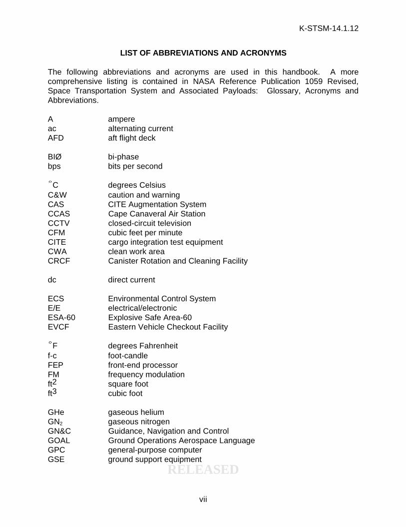
LIST OF ABBREVIATIONS AND ACRONYMS
The following abbreviations and acronyms are used in this handbook. A morecomprehensive listing is contained in NASA Reference Publication 1059 Revised,Space Transportation System and Associated Payloads: Glossary, Acronyms andAbbreviations.
A ampereac alternating currentAFD aft flight deck
BIØ bi-phasebps bits per second
§C degrees CelsiusC&W caution and warningCAS CITE Augmentation SystemCCAS Cape Canaveral Air StationCCTV closed-circuit televisionCFM cubic feet per minuteCITE cargo integration test equipmentCWA clean work areaCRCF Canister Rotation and Cleaning Facility
dc direct current
ECS Environmental Control SystemE/E electrical/electronicESA-60 Explosive Safe Area-60EVCF Eastern Vehicle Checkout Facility
§F degrees Fahrenheitf-c foot-candleFEP front-end processorFM frequency modulationft2 square footft3 cubic foot
GHe gaseous heliumGN2 gaseous nitrogenGN&C Guidance, Navigation and ControlGOAL Ground Operations Aerospace LanguageGPC general-purpose computerGSE ground support equipment
K-STSM-14.1.12
RELEASED
viii
LIST OF ABBREVIATIONS AND ACRONYMS (continued)
HEF hypergolic exhaust fanHEPA high efficiency particulate airHIM hardware interface moduleHVAC heating, ventilation and air-conditioningHz hertz
I/F TD interface terminal distributorin inchIRIG Interrange Instrumentation GroupIUS Inertial Upper-Stage
KSC John F. Kennedy Space Centerkbps kilobits per second
L literlb poundlm lumenLPS Launch Processing SystemLSSM Launch Site Support Manager
m meterMDM multiplexer/demultiplexerMHz megahertzMLP mobile launch platformmm millimeterMMSE Multiuse Mission Support EquipmentMTU master timing unit
NPF NAVSTAR Processing FacilityNVR Non-Volatile Residue
O&C Operations and Checkout (Building)OIS-D Operational Intercommunication System-DigitalOMI Operations and Maintenance InstructionOSB Operations Support BuildingOTV operational television
P polePA public addressPACAS Personnel Access Control Accountability SystemPAM Payload Assist ModulePCMMU Pulse Code Modulation Master Unit
K-STSM-14.1.12
RELEASED
ix
LIST OF ABBREVIATIONS AND ACRONYMS (continued)
PDI Payload Data InterleaverPDMS Payload Data Management SystemPETS Payload Environmental Transportation SystemPh phasePI payload interrogatorPL PayloadsPR payload recorderPOCC Payload Operations Control CenterPOL Petroleum, Oil and LubricantsPPF Payload Processing FacilityPSA power supply assemblypsig pounds per square inch gagePSP payload signal processorPSTF Payload Spin Test Facility (CCAS)
RPA record and playback assemblyRSS Rotating Service StructureRTG radioisotope thermoelectric generatorRTG-F RTG-Facility
SID Standard Interface DocumentSM System ManagementSMCH standard mixed cable harnessSSP standard switch panelSTS Space Transportation SystemTLM telemetryT-0 Time Zero (lift-off)
V voltV&DA video and data assemblyVPF Vertical Processing FacilityVPHD vertical payload handling deviceVp-p volts peak-to-peakVRSS Video Routing Switcher SystemW wireWBDI wide-band data interleaverWBT wide-band terminalWP waterproofXo X-axis of orbiterXp explosion-proof
K-STSM-14.1.12
RELEASED
x
THIS PAGE INTENTIONALLY LEFT BLANK
K-STSM-14.1.12
RELEASED
xi
FOREWORD
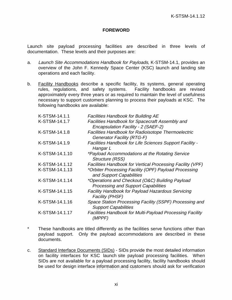
Launch site payload processing facilities are described in three levels ofdocumentation. These levels and their purposes are:
a. Launch Site Accommodations Handbook for Payloads, K-STSM-14.1, provides anoverview of the John F. Kennedy Space Center (KSC) launch and landing siteoperations and each facility.
b. Facility Handbooks describe a specific facility, its systems, general operatingrules, regulations, and safety systems. Facility handbooks are revisedapproximately every three years or as required to maintain the level of usefulnessnecessary to support customers planning to process their payloads at KSC. Thefollowing handbooks are available:
K-STSM-14.1.1 Facilities Handbook for Building AEK-STSM-14.1.7 Facilities Handbook for Spacecraft Assembly and
Encapsulation Facility - 2 (SAEF-2)K-STSM-14.1.8 Facilities Handbook for Radioisotope Thermoelectric
Generator Facility (RTG-F)K-STSM-14.1.9 Facilities Handbook for Life Sciences Support Facility -
Hangar LK-STSM-14.1.10 *Payload Accommodations at the Rotating Service
Structure (RSS)K-STSM-14.1.12 Facilities Handbook for Vertical Processing Facility (VPF)K-STSM-14.1.13 *Orbiter Processing Facility (OPF) Payload Processing
and Support CapabilitiesK-STSM-14.1.14 *Operations and Checkout (O&C) Building Payload
Processing and Support CapabilitiesK-STSM-14.1.15 Facility Handbook for Payload Hazardous Servicing
Facility (PHSF)K-STSM-14.1.16 Space Station Processing Facility (SSPF) Processing and
Support CapabilitiesK-STSM-14.1.17 Facilities Handbook for Multi-Payload Processing Facility
(MPPF)
* These handbooks are titled differently as the facilities serve functions other thanpayload support. Only the payload accommodations are described in thesedocuments.
c. Standard Interface Documents (SIDs) - SIDs provide the most detailed informationon facility interfaces for KSC launch site payload processing facilities. WhenSIDs are not available for a payload processing facility, facility handbooks shouldbe used for design interface information and customers should ask for verification
K-STSM-14.1.12
RELEASED
xii
of any areas of concern. The Payload Strongback and the PayloadEnvironmental Transportation System (PETS) Multiuse Container do not havefacility handbooks, and in these cases, only the SIDs will be used. Customersmay obtain copies of any of the following SIDs from their respective Launch SiteSupport Manager (LSSM):
SID 79K12170 Payload Ground Transportation CanisterSID 79K16210 Vertical Processing FacilitySID 79K16211 Horizontal Processing Facility (O&C Building)SID 79K17644 Payload StrongbackSID 79K18218 Launch Pad 39ASID 79K28802 Launch Pad 39BSID 79K18745 Orbiter Processing FacilitySID 82K00463 Payload Environmental Transportation System Multiuse
ContainerSID 82K00760 Space Station Processing FacilitySID 82K03223 Multi-Payload Processing Facility
K-STSM-14.1.12
RELEASED
1-1
SECTION I
INTRODUCTION
1.1 PURPOSE
The purpose of this handbook is to provide basic information on the payloadprocessing and support capabilities available in the Vertical Processing Facility (VPF)at John F. Kennedy Space Center (KSC). The VPF is primarily used to integratevertically-processed payloads into specific mission configurations and download manyof the payloads. Integration activities typically include installing a payload into a testcell in its relative flight position, simulating orbiter-to-payload interface verification testsand performing preorbiter tasks such as category B ordnance installation andconnection. The VPF floor space can also be used as a payload processing facility(PPF) to accommodate the overflow from other facilities.
Before integrated payload operations begin at the VPF, most payloads undergo build-up and test or other off-line processing functions on the VPF floor or in PPFs located atthe Cape Canaveral Air Station (CCAS) and/or KSC (see figure 1-1). The PPFs areselected by the KSC Launch Site Support Manager (LSSM), the Launch Site SupportTeam and the payload owner based on specific payload requirements and the overallKSC and CCAS schedules. The handbooks listed in the Foreword assist in making thisdetermination.
1.2 SCOPE
This handbook describes the capabilities of and standardized interfaces within theVPF. It is intended to be used by the payload organization as a guide for planningpayload activities in the VPF.
1.3 CUSTOMER CHARGE
Use of the VPF as a payload integration facility is considered a standard service.Support for payload stand-alone testing (i.e., use as a Payload Processing Facility) orunique services could result in additional charges.
1.4 FACILITY ACCOMMODATIONS
The facility accommodations available to the customer support a variety of NASA andNASA customer payloads and may be required to accommodate payload elementsbeing processed simultaneously. The customer must be aware during the designdevelopment phase that there is the potential of sharing facilities with other payloadelements. Individual payload customer requirements should be coordinated closelywith the LSSM to ensure that support is available when needed.
K-STSM-14.1.12
RELEASED
1-2
K-STSM-14.1.12
RELEASED
1-3
Most vertical payload elements -- both deployable and non-deployable -- assigned to aparticular mission will be integrated/processed in the VPF. Testing requirementsinclude payload safety and the interface between the payload and the orbiter. Payloadelements are combined with other elements to form a total payload complement for asingle mission. The customer will participate throughout the entire payload processingflow.
Payload processing within the VPF will vary depending on the type of payload involved.A spacecraft that is already mated with an upper stage (e.g., a deployable payload), isinstalled into one of two test cells where it will be supported by the Vertical PayloadHandling Device (VPHD). Spacecraft using an Inertial Upper-Stage (IUS) will be matedto the IUS previously installed in one of the two test cells. The entire payloadcomplement for a mission will be stacked in a single VPF test cell. Individual payloadelements will undergo any necessary stand-alone testing before any combined payloadtesting or simulated orbiter-to-payload testing is performed. VPF testing will includesimulated orbiter/payload T-0 umbilical functions with GSE interfaces provided in theVPF similar to those in the Mobile Launch Platform (MLP) room 10-A. These interfacesare described in KSC-DL-522, Payload/GSE/Data System Interface User's Guide forthe Vertical Processing Facility.
After all testing has been completed, the payload canister -- supported vertically on thetransporter -- will be moved to the test cell. The canister is positioned so that theVPHD can transfer the entire payload complement into the canister. This is thenmoved to the Rotating Service Structure (RSS) at Pads A or B. A payload complementreturning from the OPF to the VPF highbay in the payload canister, arrives in ahorizontal mode. The payload elements are removed individually and installed intotheir shipping containers/transporters for transport from the VPF. Customers should befamiliar with the Emergency Preparedness Plan, MDC Y1009.
1.5 EMERGENCY PLANNING AND COMMUNITY RIGHT-TO-KNOW
The Emergency Planning and Community Right-to-Know Act, Title III of the SuperfundAmendments and Reauthorization Act of 1986, requires persons to report the amountand location of hazardous chemicals produced, stored, used, or released to theenvironment each year. Customers are required to complete KSC form 28-185,Environmental Health Protection Program Toxic Substance Registry System (TSRS)Inventory and provide Material Safety Data Sheets (MSDS) for each chemical broughtonto KSC. All forms must be sent to the LSSM 90 days prior to customer arrival.
1.6 HAZARDOUS AND CONTROLLED WASTE
All waste generated at KSC must be managed in accordance with the requirements ofKennedy Handbook (KHB) 8800.7, Hazardous Waste Management. Before arrival,customers will complete KSC Form 26-551, Process Waste Questionnaire (PWQ)
K-STSM-14.1.12
RELEASED
1-4
which will identify any potential hazardous and/or controlled waste the customerexpects to generate during processing.
A satellite accumulation area (SAA) will be established in facility areas which havebeen identified as waste generation sites. SAAs will comply with the intent of theResource Conservation and Recovery Act of 1976 (RCRA), which established anationwide program to regulate the generation, storage, transportation, treatment, anddisposal of hazardous and controlled waste. Regulations for the generation, controland disposal of waste at the launch site are strictly enforced, and customers will berequired to coordinate any waste operations or problems with their assigned LSSM.
K-STSM-14.1.12
RELEASED
2-1
SECTION II
FACILITY DESCRIPTION
Figure 2-1. Aerial Photograph of the VPF Complex
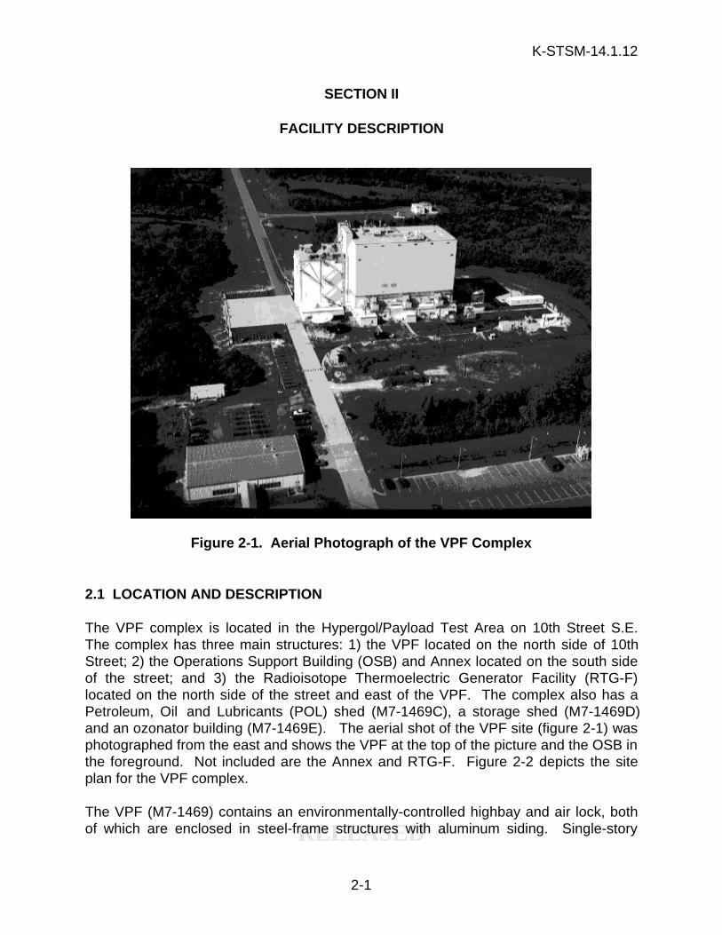
2.1 LOCATION AND DESCRIPTION
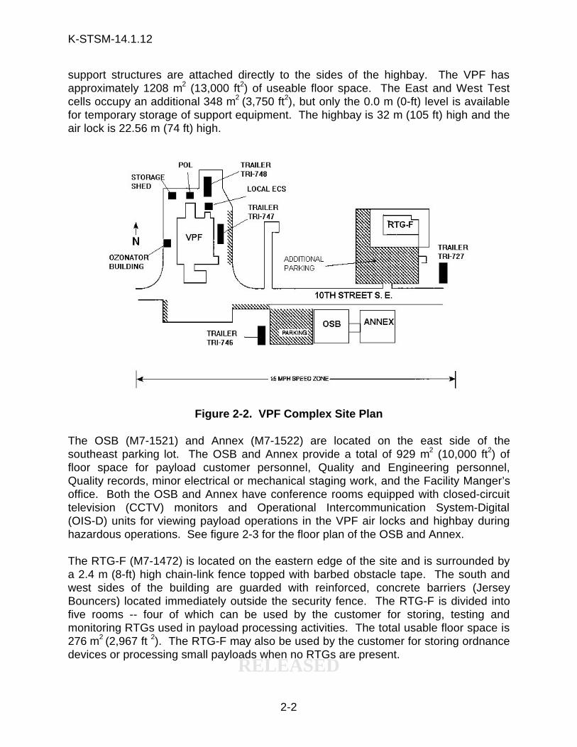
The VPF complex is located in the Hypergol/Payload Test Area on 10th Street S.E.The complex has three main structures: 1) the VPF located on the north side of 10thStreet; 2) the Operations Support Building (OSB) and Annex located on the south sideof the street; and 3) the Radioisotope Thermoelectric Generator Facility (RTG-F)located on the north side of the street and east of the VPF. The complex also has aPetroleum, Oil and Lubricants (POL) shed (M7-1469C), a storage shed (M7-1469D)and an ozonator building (M7-1469E). The aerial shot of the VPF site (figure 2-1) wasphotographed from the east and shows the VPF at the top of the picture and the OSB inthe foreground. Not included are the Annex and RTG-F. Figure 2-2 depicts the siteplan for the VPF complex.
The VPF (M7-1469) contains an environmentally-controlled highbay and air lock, bothof which are enclosed in steel-frame structures with aluminum siding. Single-story
K-STSM-14.1.12
RELEASED
2-2
support structures are attached directly to the sides of the highbay. The VPF hasapproximately 1208 m2 (13,000 ft2) of useable floor space. The East and West Testcells occupy an additional 348 m2 (3,750 ft2), but only the 0.0 m (0-ft) level is availablefor temporary storage of support equipment. The highbay is 32 m (105 ft) high and theair lock is 22.56 m (74 ft) high.
Figure 2-2. VPF Complex Site Plan
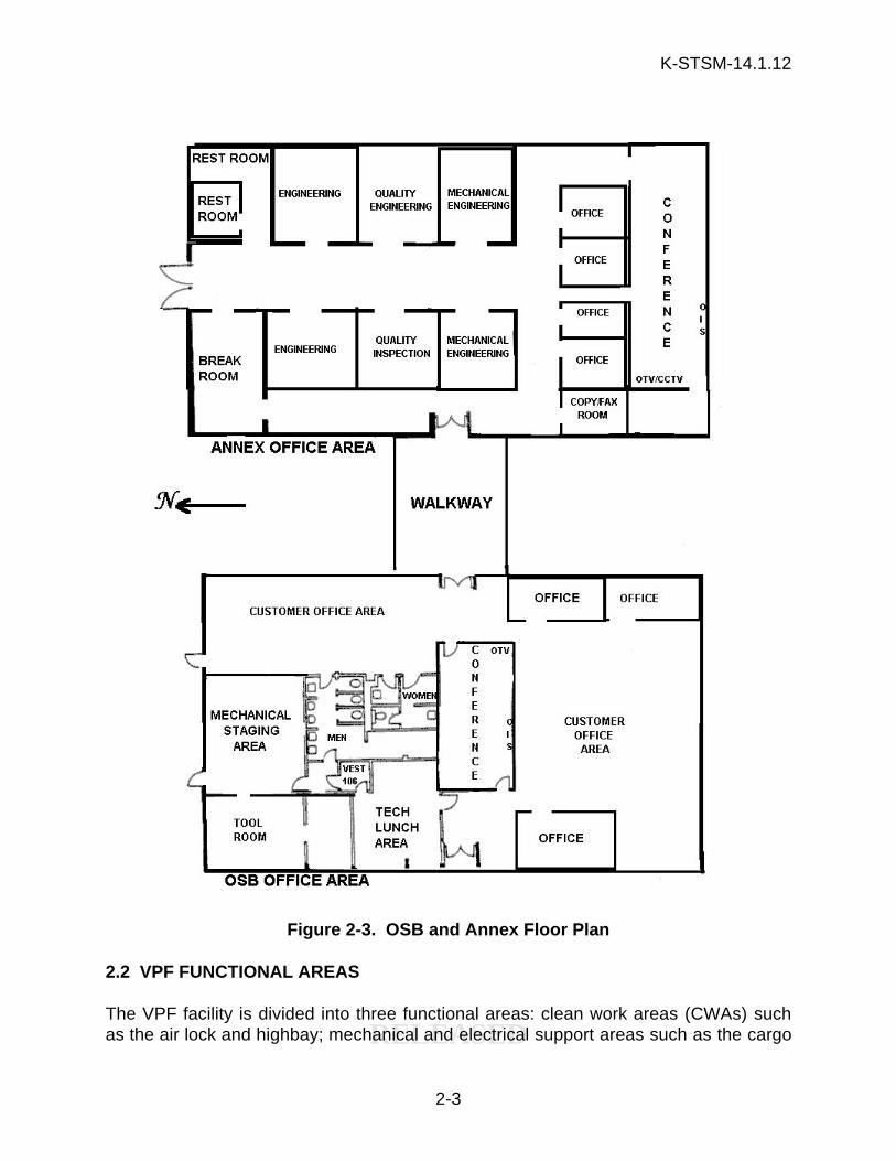
The OSB (M7-1521) and Annex (M7-1522) are located on the east side of thesoutheast parking lot. The OSB and Annex provide a total of 929 m2 (10,000 ft2) offloor space for payload customer personnel, Quality and Engineering personnel,Quality records, minor electrical or mechanical staging work, and the Facility Manger’soffice. Both the OSB and Annex have conference rooms equipped with closed-circuittelevision (CCTV) monitors and Operational Intercommunication System-Digital(OIS-D) units for viewing payload operations in the VPF air locks and highbay duringhazardous operations. See figure 2-3 for the floor plan of the OSB and Annex.
The RTG-F (M7-1472) is located on the eastern edge of the site and is surrounded bya 2.4 m (8-ft) high chain-link fence topped with barbed obstacle tape. The south andwest sides of the building are guarded with reinforced, concrete barriers (JerseyBouncers) located immediately outside the security fence. The RTG-F is divided intofive rooms -- four of which can be used by the customer for storing, testing andmonitoring RTGs used in payload processing activities. The total usable floor space is276 m2 (2,967 ft 2). The RTG-F may also be used by the customer for storing ordnancedevices or processing small payloads when no RTGs are present.
K-STSM-14.1.12
RELEASED
2-3
Figure 2-3. OSB and Annex Floor Plan
2.2 VPF FUNCTIONAL AREAS
The VPF facility is divided into three functional areas: clean work areas (CWAs) suchas the air lock and highbay; mechanical and electrical support areas such as the cargo
K-STSM-14.1.12
RELEASED
2-4
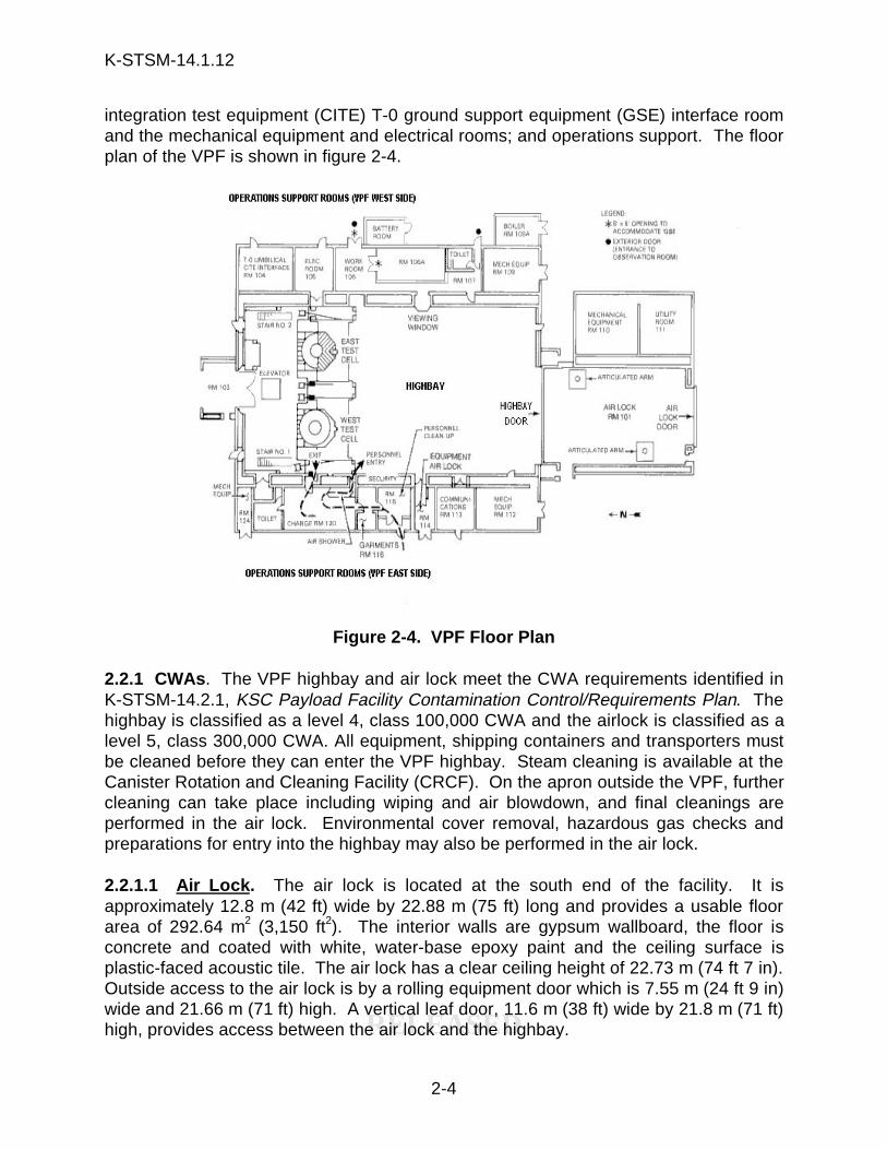
integration test equipment (CITE) T-0 ground support equipment (GSE) interface roomand the mechanical equipment and electrical rooms; and operations support. The floorplan of the VPF is shown in figure 2-4.
Figure 2-4. VPF Floor Plan
2.2.1 CWAs . The VPF highbay and air lock meet the CWA requirements identified inK-STSM-14.2.1, KSC Payload Facility Contamination Control/Requirements Plan. Thehighbay is classified as a level 4, class 100,000 CWA and the airlock is classified as alevel 5, class 300,000 CWA. All equipment, shipping containers and transporters mustbe cleaned before they can enter the VPF highbay. Steam cleaning is available at theCanister Rotation and Cleaning Facility (CRCF). On the apron outside the VPF, furthercleaning can take place including wiping and air blowdown, and final cleanings areperformed in the air lock. Environmental cover removal, hazardous gas checks andpreparations for entry into the highbay may also be performed in the air lock.
2.2.1.1 Air Lock. The air lock is located at the south end of the facility. It isapproximately 12.8 m (42 ft) wide by 22.88 m (75 ft) long and provides a usable floorarea of 292.64 m2 (3,150 ft2). The interior walls are gypsum wallboard, the floor isconcrete and coated with white, water-base epoxy paint and the ceiling surface isplastic-faced acoustic tile. The air lock has a clear ceiling height of 22.73 m (74 ft 7 in).Outside access to the air lock is by a rolling equipment door which is 7.55 m (24 ft 9 in)wide and 21.66 m (71 ft) high. A vertical leaf door, 11.6 m (38 ft) wide by 21.8 m (71 ft)high, provides access between the air lock and the highbay.

K-STSM-14.1.12
RELEASED
2-5
The air lock is equipped with service connections for electrical power, static grounding,compressed air, vacuum, and gaseous nitrogen (GN2). Vacuum and compressed airservice connections are also located outside the airlock so the canister transporter,GSE, GSE transporter, payload transporters, etc., can be cleaned before entering theair lock.
2.2.1.2 Highbay. The highbay is 22.88 m (75 ft) wide by 45.75 m (150 ft) long and has1045.13 m2 (11,250 ft2) of floor space. The interior walls are gypsum wallboard, thefloor is concrete and coated with white, water-base epoxy paint and the ceiling surfaceis plastic-faced acoustic tile. The highbay has a ceiling height of 32 m (105 ft). Theceiling height is restricted by the lower surface of the bridge crane rail which is at the29.6 m (97 ft) level. Personnel and small equipment must enter the highbay throughthe air showers.
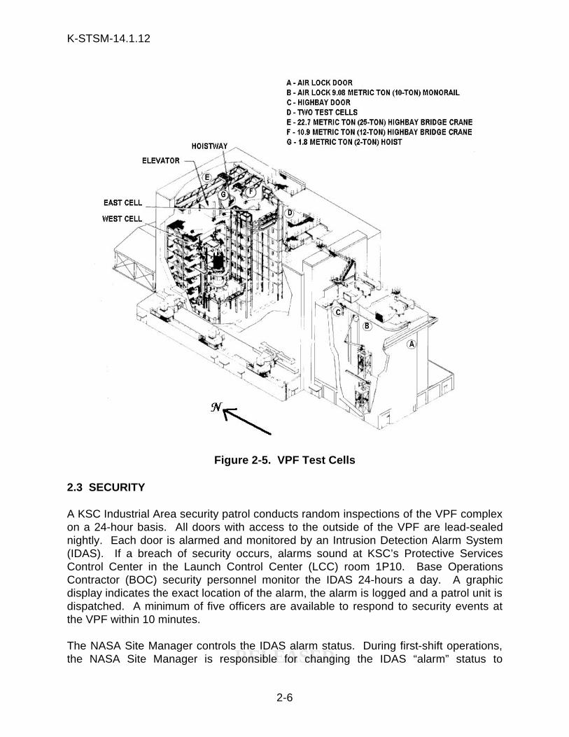
2.2.1.3 Highbay Test Cells. The test cells are located at the north end of the highbay.These multiple-platform test cells occupy a floor area of approximately 22.86 m (75 ft)by 15 m (50 ft) and are about 22.86 m (75 ft) high. The test cells are designed toaccommodate Space Shuttle payloads within the design parameters of the orbiterpayload bay or a 4.57 m (15 ft) diameter by 18.29 m (60 ft) length and 29,484 kilogram(kg) (65,000 lb) maximum weight. Storage space is available on the 0.0 m (0-ft) levelfor temporary storage of support equipment. The allocation of space for customer GSEwill be evaluated on a mission-by-mission basis. Figure 2-5 depicts the east and westtest cells located in the north end of the highbay.
The highbay test cells may be used to process a variety of payload elements thatrequire an environmentally clean, temperature and humidity-controlled atmosphere.Current planning includes payload element integration and checkout, total payloadintegration, orbiter interface verification, installation into the payload canister, and finalpreparations prior to transportation to the launch complex.
2.2.2 MECHANICAL AND ELECTRICAL SUPPORT AREAS. Mechanical andElectrical support rooms are located on both the east and west sides of the highbay.The east side has a T-0 umbilical CITE interface room, mechanical and electricalequipment rooms and a test equipment room with a raised floor for cable routing. Thewest side has two mechanical equipment rooms and a communications room, andthese rooms can only be accessed from outside the VPF. For more details on theseintegration and interface areas, refer to KSC-DL-522, Payload/GSE/Data SystemInterface User's Guide for the Vertical Processing Facility.
2.2.3 OPERATIONS SUPPORT. The following operations support rooms are locatedalong the west side of the highbay: a security station; a clean room garment supplyroom; a change room with air shower and restroom facilities; and an equipmentcleaning room with access to the highbay area.
K-STSM-14.1.12
RELEASED
2-6
Figure 2-5. VPF Test Cells
2.3 SECURITY
A KSC Industrial Area security patrol conducts random inspections of the VPF complexon a 24-hour basis. All doors with access to the outside of the VPF are lead-sealednightly. Each door is alarmed and monitored by an Intrusion Detection Alarm System(IDAS). If a breach of security occurs, alarms sound at KSC’s Protective ServicesControl Center in the Launch Control Center (LCC) room 1P10. Base OperationsContractor (BOC) security personnel monitor the IDAS 24-hours a day. A graphicdisplay indicates the exact location of the alarm, the alarm is logged and a patrol unit isdispatched. A minimum of five officers are available to respond to security events atthe VPF within 10 minutes.
The NASA Site Manager controls the IDAS alarm status. During first-shift operations,the NASA Site Manager is responsible for changing the IDAS “alarm” status to
K-STSM-14.1.12
RELEASED
2-7
“access.” The access mode enables BOC to monitor the number of door openings atthe facility and instructs console operators not to dispatch security/emergency services.The Payload Ground Operations Contractor (PGOC) maintains security within thefacilities as required by the customer. Access requirements to the facility after 4:45p.m. on weekdays, weekends or holidays must be arranged with PGOC Security at theAccess Control Monitor (ACM) station located in the O&C (room 1245). The ACMstation can be reached 24-hours a day at 867-7664. Additional security is a non-standard service and may be arranged by the payload organization/customer assignedto the facility.
2.4 PERSONNEL ACCESS
Personnel who require access to KSC must be issued a NASA/ESMC picture badge ormachine pass. Access to the VPF is permitted only to personnel with a valid KSC-areapermit or Temporary Area Authorization (TAA). Those with a “to be escorted” TAAmust be escorted by a properly badged individual at all times and may only enter theVPF with an escort.
Access to the VPF is controlled by a Personnel Access Control Accountability System(PACAS) located in room 115. PACAS monitors and logs each person who enters thefacility; the time of entrance and the time of exit. PACAS cards are issued through theNASA Launch Site Support Office. Access to the VPF highbay is controlled by PACASand cipher-locked areas. All personnel entering the CWA must obtain and beresponsible for the appropriate garments from room 116 and conform to the rules andregulations (table 2-1) established for VPF operations. Garments assigned to workersare not to leave the facility. Specific CWA environmental requirements and theenvironmental monitoring system (EMS) are discussed in detail in section 3.10.
2.5 REQUIREMENTS AND SPECIAL CONSIDERATIONS
Because much of the work performed at the VPF is hazardous, safety restrictions, strictsecurity and personnel controls are enforced. A badge exchange board within thefacility allows identification of personnel in the VPF highbay. During hazardousoperations, a guard restricts vehicle access to the site complex. Amber and redbeacon lights are located on the outside of the VPF at each of the four corners. Fireprotection systems, sensors and warning devices are used to alert personnel in theevent hazardous conditions arise.
The amount of explosives and propellants that can be housed within the VPF is limited.Therefore, the NASA Safety Office must approve the quantity of propellant used byeach payload before payload processing activities begin in the VPF. Customers areadvised to contact their LSSMs as early as possible to ensure the payload processingrequirements can be met.
K-STSM-14.1.12
RELEASED
2-8
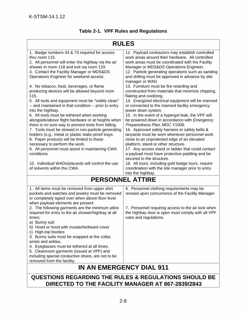
Table 2-1. VPF Rules and Regulations
RULES1. Badge numbers 43 & 73 required for accessthru room 115.2. All personnel will enter the highbay via the airshower in room 118 and exit via room 119.
11. Payload contractors may establish controlledwork areas around their hardware. All controlledwork areas must be coordinated with the FacilityManager or MDS&DS Operations Engineer.
3. Contact the Facility Manager or MDS&DSOperations Engineer for weekend access.
12. Particle generating operations such as sandingand drilling must be approved in advance by sitemanager or WAD.
4. No tobacco, food, beverages, or flameproducing devices will be allowed beyond room115.
13. Furniture must be fire retarding andconstructed from materials that minimize chipping,flaking and oxidizing.
5. All tools and equipment must be “visibly clean”-- and maintained in that condition -- prior to entryinto the highbay.
14. Energized electrical equipment will be mannedor connected to the manned facility emergencypower down system.
6. All tools must be tethered when workingalongside/above flight hardware or at heights whenthere is no sure way to prevent tools from falling.
15. In the event of a hypergol leak, the VPF willbe powered down in accordance with EmergencyPreparedness Plan, MDC Y1009.
7. Tools must be stowed in non-particle generatingholders (e.g., metal or plastic static-proof trays.8. Paper products will be limited to thosenecessary to perform the work.
16. Approved safety harness or safety belts &lanyards must be worn whenever personnel workclose to an unprotected edge of an elevatedplatform, stand or other structure.
9. All personnel must assist in maintaining CWAconditions.
17. Any access stand or ladder that could contacta payload must have protective padding and besecured to the structure.
10. Individual WADs/placards will control the useof solvents within the CWA.
18. All tours, including gold badge tours, requirecoordination with the site manager prior to entryinto the highbay.
PERSONNEL ATTIRE1. All items must be removed from upper shirtpockets and watches and jewelry must be removedor completely taped over when above floor levelwhen payload elements are present.
6. Personnel clothing requirements may berevised upon concurrence of the Facility Manager.
2. The following garments are the minimum attirerequired for entry to the air shower/highbay at alltimes:a) Bunny suitb) Hood or hood with mustache/beard coverc) High-top booties
7. Personnel requiring access to the air lock whenthe highbay door is open must comply with all VPFrules and regulations.
3. Bunny suits must be snapped at the collar,wrists and ankles.4. Eyeglasses must be tethered at all times.5. Cleanroom garments (issued at VPF) andincluding special conductive shoes, are not to beremoved from the facility.
IN AN EMERGENCY DIAL 911QUESTIONS REGARDING THE RULES & REGULATIONS SHOULD BE
DIRECTED TO THE FACILITY MANAGER AT 867-2839/2843
K-STSM-14.1.12
RELEASED
3-1
SECTION III
MECHANICAL SYSTEMS
3.1 TEST CELL ELEVATING PLATFORMS
Access to the highbay test cells is provided by access platforms. Six, fixed-accesslevels are located on the north side of each cell at heights of 4.57 m (15 ft), 7.62 m (25ft), 10.67 m (35 ft), 13.72 m (45 ft), 16.76 m (55 ft), and 19.81 m (65 ft) above the floor.The platform at the 22.86 m (75-ft) level is used to house the elevator motor andcontrols, the 1.81 metric ton (2-ton) hoist and the aft flight deck (AFD) simulator. Theretractable and fixed platforms are designed to access the payload exterior (see figure3-1).
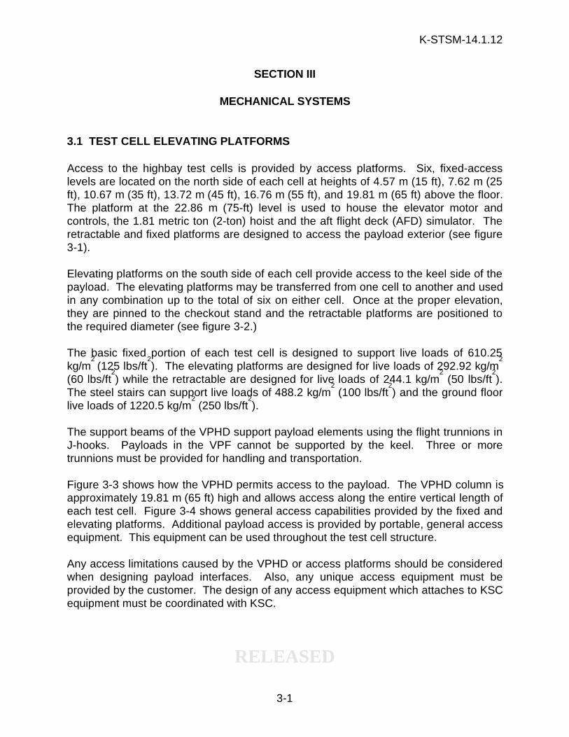
Elevating platforms on the south side of each cell provide access to the keel side of thepayload. The elevating platforms may be transferred from one cell to another and usedin any combination up to the total of six on either cell. Once at the proper elevation,they are pinned to the checkout stand and the retractable platforms are positioned tothe required diameter (see figure 3-2.)
The basic fixed portion of each test cell is designed to support live loads of 610.25kg/m
2 (125 lbs/ft
2). The elevating platforms are designed for live loads of 292.92 kg/m
2
(60 lbs/ft2) while the retractable are designed for live loads of 244.1 kg/m
2 (50 lbs/ft
2).
The steel stairs can support live loads of 488.2 kg/m2 (100 lbs/ft
2) and the ground floor
live loads of 1220.5 kg/m2 (250 lbs/ft
2).
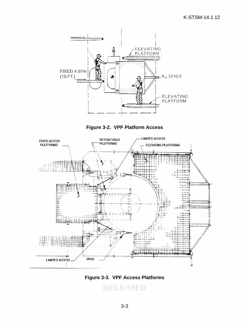
The support beams of the VPHD support payload elements using the flight trunnions inJ-hooks. Payloads in the VPF cannot be supported by the keel. Three or moretrunnions must be provided for handling and transportation.
Figure 3-3 shows how the VPHD permits access to the payload. The VPHD column isapproximately 19.81 m (65 ft) high and allows access along the entire vertical length ofeach test cell. Figure 3-4 shows general access capabilities provided by the fixed andelevating platforms. Additional payload access is provided by portable, general accessequipment. This equipment can be used throughout the test cell structure.
Any access limitations caused by the VPHD or access platforms should be consideredwhen designing payload interfaces. Also, any unique access equipment must beprovided by the customer. The design of any access equipment which attaches to KSCequipment must be coordinated with KSC.

K-STSM-14.1.12
RELEASED
3-2
Figure 3-1. VPF Test Cell Elevation
K-STSM-14.1.12
RELEASED
3-3
Figure 3-2. VPF Platform Access
Figure 3-3. VPF Access Platforms

K-STSM-14.1.12
RELEASED
3-4
Figure 3-4. VPF Elevating Platforms
3.2 MATERIAL HANDLING EQUIPMENT
3.2.1 CRANES. A monorail track for a 9.08 metric ton (10-ton) capacity hoist ismounted in the ceiling of the air lock. The beam is constructed so that the hoist can bepositioned in a remote corner when not in use. The hoist travels north/south in thecenterline with no lateral movement and has a maximum hook height of 20.02 m (65 ft 8in) and a minimum of 0.97 m (3 ft 2 in) from the floor. The crane services the center ofthe air lock to a point 7.01 m (23 ft) from the outside door where the monorail curves tothe east, giving service up to 1.52 m (5 ft) from the air lock east wall. See figure 3-5 forhoist hook dimensions.
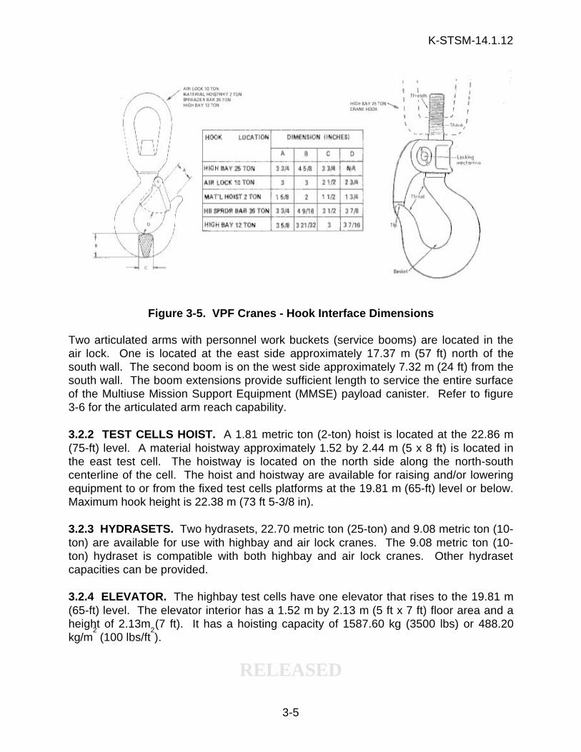
Two bridge cranes are located in the VPF highbay. One crane has a 22.68 metric ton(25-ton) capacity and a 10.89 metric ton (12-ton) crane was added south of the 25-toncrane to increase the hoist capacity to a total of 42.66 metric tons (37 tons). In additionto these two bridge cranes, a 1.8 metric ton (2-ton) hoist is located on the workstand atthe 22.86 m (75 ft) level. The hook height for the 22.68 metric ton (25-ton) crane is28.65 m (94 ft) and the hook height for the 10.89 metric ton (12-ton) crane is 28.35 m(93 ft). The travel of the crane from the east and west walls is 2.4 m (7 ft 10 in) for the22.68 metric ton (25-ton) crane and 1.63 m (5 ft 4 in) for the 10.89 metric ton (12-ton)crane. Travel from the south wall (not rail stop) is 10.44 m (34 ft 3 in) for the 22.68metric ton (25-ton) crane and 4.17 m (13 ft 8 in) for the 10.89 metric ton (12-ton) crane.Hook travel from the edge of the test cell from the north wall is 2.59 m (8 ft 6 in) for bothcranes. Hoist hook interface dimensions for both cranes are shown in figure 3-5.Note: when the 42.66 metric ton (37-ton) lifting capacity is effected, theequalizing hoist beam limits the highbay maximum hook height to 26.56 m (87 ft3 in).
K-STSM-14.1.12
RELEASED
3-5
Figure 3-5. VPF Cranes - Hook Interface Dimensions
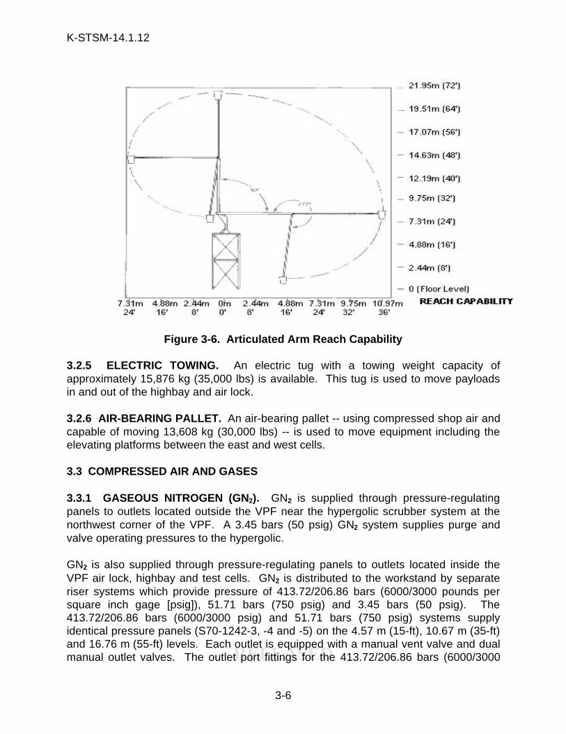
Two articulated arms with personnel work buckets (service booms) are located in theair lock. One is located at the east side approximately 17.37 m (57 ft) north of thesouth wall. The second boom is on the west side approximately 7.32 m (24 ft) from thesouth wall. The boom extensions provide sufficient length to service the entire surfaceof the Multiuse Mission Support Equipment (MMSE) payload canister. Refer to figure3-6 for the articulated arm reach capability.
3.2.2 TEST CELLS HOIST. A 1.81 metric ton (2-ton) hoist is located at the 22.86 m(75-ft) level. A material hoistway approximately 1.52 by 2.44 m (5 x 8 ft) is located inthe east test cell. The hoistway is located on the north side along the north-southcenterline of the cell. The hoist and hoistway are available for raising and/or loweringequipment to or from the fixed test cells platforms at the 19.81 m (65-ft) level or below.Maximum hook height is 22.38 m (73 ft 5-3/8 in).
3.2.3 HYDRASETS. Two hydrasets, 22.70 metric ton (25-ton) and 9.08 metric ton (10-ton) are available for use with highbay and air lock cranes. The 9.08 metric ton (10-ton) hydraset is compatible with both highbay and air lock cranes. Other hydrasetcapacities can be provided.
3.2.4 ELEVATOR. The highbay test cells have one elevator that rises to the 19.81 m(65-ft) level. The elevator interior has a 1.52 m by 2.13 m (5 ft x 7 ft) floor area and aheight of 2.13m (7 ft). It has a hoisting capacity of 1587.60 kg (3500 lbs) or 488.20kg/m
2 (100 lbs/ft2).
K-STSM-14.1.12
RELEASED
3-6
Figure 3-6. Articulated Arm Reach Capability
3.2.5 ELECTRIC TOWING. An electric tug with a towing weight capacity ofapproximately 15,876 kg (35,000 lbs) is available. This tug is used to move payloadsin and out of the highbay and air lock.
3.2.6 AIR-BEARING PALLET. An air-bearing pallet -- using compressed shop air andcapable of moving 13,608 kg (30,000 lbs) -- is used to move equipment including theelevating platforms between the east and west cells.
3.3 COMPRESSED AIR AND GASES
3.3.1 GASEOUS NITROGEN (GN2). GN2 is supplied through pressure-regulatingpanels to outlets located outside the VPF near the hypergolic scrubber system at thenorthwest corner of the VPF. A 3.45 bars (50 psig) GN2 system supplies purge andvalve operating pressures to the hypergolic.
GN2 is also supplied through pressure-regulating panels to outlets located inside theVPF air lock, highbay and test cells. GN2 is distributed to the workstand by separateriser systems which provide pressure of 413.72/206.86 bars (6000/3000 pounds persquare inch gage [psig]), 51.71 bars (750 psig) and 3.45 bars (50 psig). The413.72/206.86 bars (6000/3000 psig) and 51.71 bars (750 psig) systems supplyidentical pressure panels (S70-1242-3, -4 and -5) on the 4.57 m (15-ft), 10.67 m (35-ft)and 16.76 m (55-ft) levels. Each outlet is equipped with a manual vent valve and dualmanual outlet valves. The outlet port fittings for the 413.72/206.86 bars (6000/3000
K-STSM-14.1.12
RELEASED
3-7
psig) is 6.35 mm (1/4 in), KC 124C4, bulkhead union. The outlet port fittings for the51.71 bars (750 psig) system is 12.7 mm (1/2 in), KC 124C8, bulkhead union. The413.72/206.86 bars (6000/3000 psig) system also supplies other pressure panels whichprovide purge pressures for the waveguide systems and intercom panels. It suppliestwo pressure panels (S70-1242-7 and -8) on the west wall of the air lock. Outletconnections on these panels are 6.35 mm (1/4 in), KC 124C4, bulkhead unions.
The 3.45 bars (50 psig) and the 0.34 bars (5 psig) systems provide the GN2 purge forthe OIS-D and RF antenna waveguide components. Refer to figure 3-7 for approximatelocations of GN2 outlets.
3.3.2 GASEOUS HELIUM (GHe). GHe is supplied through pressure-regulating panelsto outlets located throughout the test cells levels. The GHe is distributed to the testcells by separate riser systems providing pressures of 413.72/206.86 bars (6000/3000psig). GHe to the 14.57m (15-ft), 10.67 m (35-ft) and 16.76m (55-ft) levels (3 levels) issupplied through a pressure panel similar to the GN2 system. Refer to figure 3-7 forapproximate locations of GHe outlets.
3.3.3 BREATHING AIR. Breathing air (instrument purge) is supplied throughpressure-regulating panel S70-1242-1 to the 14.57 m (15-ft), 10.67 m (35-ft) and 16.76m (55-ft) test cell levels at 2400 psig. Outlet connections on these panels are 12.70mm (1/2 in), KC 124C8, bulkhead unions. Refer to figure 3-7 for approximate locationsof breathing air outlets.
3.3.4 COMPRESSED AIR. Compressed air, filtered to 1.0 micron is available on alllevels of the test cells except the 22.86 m (75-ft) level. Each outlet is equipped with ashut-off valve, a filter strainer and a manually-operable pressure reducing regulatorwith internal relief to atmosphere. The pressure reducing regulator is equipped with apressure gage indicating meter 0-20.69 bars (0-300 psig). Any pressure from 0 to 8.62bars (0 to 125 psig) is available. Outlets on the 7.62 m (25-ft), 13.72 m (45-ft) and19.81 m (65-ft) levels (3 levels) have quick-disconnect fittings (Hanson 4500). Outletshave capped fittings on the remaining levels. All outlets on the test cells are located0.305 m (1 ft) above the grating. Compressed air hose reels are located 0.83 m (2 ft 9in) above the grating and are dedicated to air wrenches to extend/retract extendableplatforms.
Compressed air 8.62 or 6.21 bars (125 psig or 90 psig) is available at other strategiclocations in the highbay and air lock. Three outlets are provided on each level --one atthe end of the center finger and one located in each of the two cells on the north wall --which are supplied with oil to operate wrenches. A closed vent system must be usedwith these outlets to prevent environmental contamination. Refer to figure 3-7 forapproximate locations of compressed air outlets.

K-STSM-14.1.12
RELEASED
3-8
3.4 VACUUM SYSTEM
The VPF vacuum system consists of 59 vacuum inlet ports, three shoe scrubbers andthree mechanical mats. Vacuum fittings are flush-mounted, wall-valve types for a 38.10mm (1.5 in) hose (Spencer 8705A Type DA). Forty-three of the vacuum inlet ports arelocated throughout the VPF -- the approximate locations are shown in figure 3-7. Theeast and west test cells have 16 vacuum inlet ports; two ports at each level beginningat the 0.305 m (1 ft) level above the grating and continuing upward in 15-footincrements to the 22.86 m (75-ft) level. The shoe scrubbers and mechanical mats areactivated/deactivated by a push button station located adjacent to the light switches inthe personnel entrance (room 117) and locker rooms. The vacuum pump produces avacuum of 0.25 bar (7 in) of mercury and is located in mechanical equipment room 110.
Figure 3-7. Compressed Air and Gases in VPF
K-STSM-14.1.12
RELEASED
3-9
3.5 HEATING, VENTILATION AND AIR-CONDITIONING (HVAC)
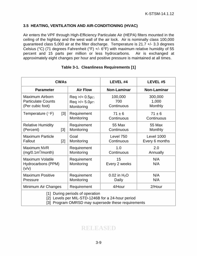
Air enters the VPF through High-Efficiency Particulate Air (HEPA) filters mounted in theceiling of the highbay and the west wall of the air lock. Air is nominally class 100,000guaranteed class 5,000 air at the filter discharge. Temperature is 21.7 +/- 3.3 degreesCelsius (°C) (71 degrees Fahrenheit (°F) +/- 6°F) with maximum relative humidity of 55percent and 15 parts per million or less hydrocarbons. Air is exchanged atapproximately eight changes per hour and positive pressure is maintained at all times.
Table 3-1. Cleanliness Requirements [1]
CWAs LEVEL #4 LEVEL #5
Parameter Air Flow Non-Laminar Non-Laminar
Maximum AirbornParticulate Counts(Per cubic foot)
Req >/= 0.5µmReq >/= 5.0µmMonitoring
100,000700
Continuous
300,0001,000
Monthly
Temperature (§F) [3] RequirementMonitoring
71 ± 6Continuous
71 ± 6Continuous
Relative Humidity(Percent) [3]
RequirementMonitoring
55 MaxContinuous
55 MaxMonthly
Maximum ParticleFallout [2]
GoalMonitoring
Level 750Continuous
Level 1000Every 6 months
Maximum NVR(mg/0.1m2/month)
RequirementMonitoring
1.0Continuous
2.0Annually
Maximum VolatileHydrocarbons (PPM)(v/v)
RequirementMonitoring
15Every 2 weeks
N/AN/A
Maximum PositivePressure
RequirementMonitoring
0.02 in H2ODaily
N/AN/A
Minimum Air Changes Requirement 4/Hour 2/Hour
[1] During periods of operation[2] Levels per MIL-STD-1246B for a 24-hour period[3] Program OMRSD may supersede these requirements
K-STSM-14.1.12
RELEASED
3-10
3.6 CONTAMINATION CONTROL AND MONITORING SYSTEMS
The VPF is a non-laminar flow CWA, and the Environmental Monitoring System (EMS)provides real-time and historical data on the parameters required to maintain a CWA.The EMS is supplemented by physical measuring techniques. Environmentalconditions are continuously monitored, stored and recorded for temperature, relativehumidity and airborne particle matter. Surface particulate matter, non-volatile residueand volatile hydrocarbon monitoring is performed by conventional methods (i.e.,witness plates). See table 3-1 for cleanliness requirements.
The Continuous Monitor/Analyzer is the heart of the EMS. The mainframe is locatedopposite the observation window in room 106 and remote from the sensors. Thesystem receives data from multiple sensor outputs connected by coaxial cable,archives it in time-correlated channels of data and provides an output to the hostcomputer system. The system provides real-time data and printed records ofenvironmental conditions and sets off an alarm when it detects an out-of-speccondition.
Sensor sets are installed in specific areas within the VPF. The highbay has sensors atthe 7.62 m (25-ft), 10.67 m (35-ft), 13.72 m (45-ft), and 16.76 m (55-ft) levels and onelocated in the air lock. Each sensor set detects particle count (i.e., 0.5 and 5 microns),temperature and relative humidity. When an out-of-spec condition occurs in any one ofthe monitored areas, the system sounds an alarm at the MDS&DS facility console. Thisconsole is monitored 24-hours a day by an Andover Controls monitoring and controlsystem which is located in building M7-458.
3.6.1 CRYOGENIC VENT. A general cryogenic vent interface is located on the northwall of the east test cell at the 10.67-m (35-ft) level. Gases are passively vented to theoutside through a 9.8 centimeter (4-in) pipe.
3.6.2 HYPERGOLIC PROPELLANT VAPOR EXHAUST SYSTEM. The hypergolexhaust fan (HEF) system can be turned on manually through a HEF control panellocated in room 115. The HEF system consists of four in-line, vane axial exhaust fanswith pneumatically-operated dampers and air grills. The fans have a total capacity of4,811,144 l/sec (102,000 cubic feet per minute (cfm)) or an equivalent of 5.6 airchanges per hour. The exhaust fans are interlocked with the air handling units whichshut down when the fans are energized. Makeup air for the exhaust system isintroduced through four supply air registers with pneumatically-operated dampers10620 L/sec (22,500 cfm total) located above the low roof levels on the east and westside of the highbay. Use of this system will contaminate the CWA with unfilteredoutside air, and it may be activated by authorized personnel only.
3.6.3 PROPELLANT WASTE DRAIN SYSTEM. The propellant waste drain system isa non-storage system that is used in the event of a spill during hypergolic operations.Drains are located on the floor beneath each workstand to collect hypergolic propellant
K-STSM-14.1.12
RELEASED
3-11
waste which is carried by buried 101.6 mm (4-in) double-wall stainless steel drain pipesto a buried double-wall stainless steel waste tank. The waste containment system canaccommodate a maximum of 18,925 L (5,000 gal) of hypergolic propellant mixed withwater. All leaks and spills must be flushed immediately with water to achieve a dilutionratio of at least one and one-half parts water to one part hypergol.
In the event of an emergency, a scrubber drain and separator tank are provided tocollect -- through a closed drain/vent system -- approximately 246 L (65 gal) ofundiluted hypergolic propellant. On each test cell at the 4.57 m (15-ft), 7.62 m (25-ft),13.72 m (45-ft), and 19.81 m (65-ft) levels (4 levels) a capped outlet and a hand-operated ball valve are provided. The system is equipped with 51.72 bars (750 psig)GN2 for aspiration operation and a fuel scrubber (S70-1094) for vapor disposal.
3.7 FIRE PROTECTION SYSTEMS
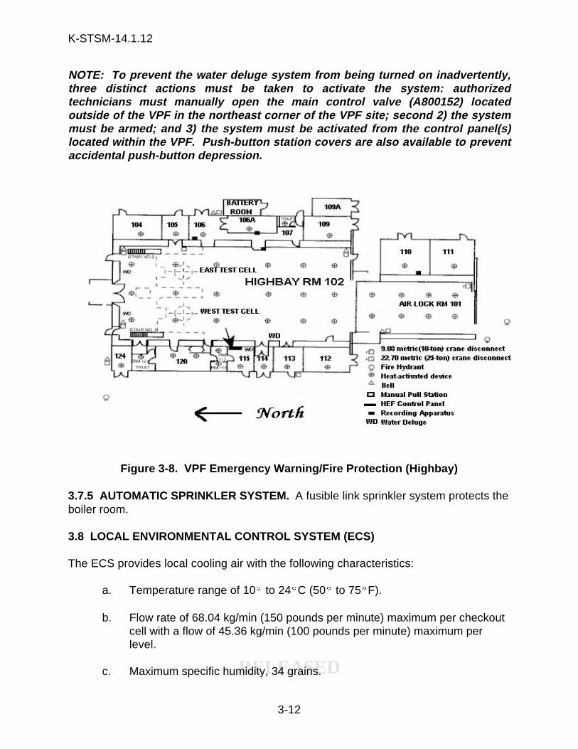
Fire protection within the VPF consists of a fire detection system, a general alarm, non-coded zone-annunciation fire alarm system, fire control equipment, and a water delugesystem. Fire hydrants are located at the exterior southwest and southeast corners ofthe air lock. A manually-activated water spray fire suppression system protects the fuelscrubber installation. During hazardous operations, KCA-013 Firewatch Procedure, willbe in effect. Figure 3-8 shows the locations of the various emergency warning systemswithin the highbay.
3.7.1 FIRE DETECTION SYSTEM. Heat activated detectors are installed in theceilings of each room. In addition, 52 ultra-violet and infrared detectors are installed onthe walls and cell areas in the highbay.
3.7.2 FIRE ALARM SYSTEM. Hand-operated, pull-type fire alarm stations are locatedat emergency exits throughout the VPF, on each side of all levels of the test cells andoutside the building. Activation of either a fire detector or fire alarm causes a signal tobe transmitted to the KSC Launch Control Center Fire Controller. At the same time thatalarm bells are sounded in and around the building, the HVAC comfort air dampersclose and the air handlers are shut down to contain the fire.
3.7.3 FIRE CONTROL EQUIPMENT. Carbon Dioxide (CO2) type BC and multipurposedry chemical type ABC fire extinguishers are located throughout the facility.
3.7.4 WATER DELUGE SYSTEM. A water deluge fire suppression system is fed froma one million gallon storage tank located at the HMF Pump Station (M7-1362) and isdivided into two independent zones (east and west cells). Push-button station controls-- capable of arming and activating the system -- are located in each test cell on the4.47 m through 19.81 m (15- through 65-ft) levels. There is also a master control panelon the west wall of the highbay and a remote-control panel in room 115 -- both of whichhave the capability of arming, activating, disarming, and deactivating both the east andwest zones. This system may only be activated by authorized personnel.
K-STSM-14.1.12
RELEASED
3-12
NOTE: To prevent the water deluge system from being turned on inadvertently,three distinct actions must be taken to activate the system: authorizedtechnicians must manually open the main control valve (A800152) locatedoutside of the VPF in the northeast corner of the VPF site; second 2) the systemmust be armed; and 3) the system must be activated from the control panel(s)located within the VPF. Push-button station covers are also available to preventaccidental push-button depression.
Figure 3-8. VPF Emergency Warning/Fire Protection (Highbay)
3.7.5 AUTOMATIC SPRINKLER SYSTEM. A fusible link sprinkler system protects theboiler room.
3.8 LOCAL ENVIRONMENTAL CONTROL SYSTEM (ECS)
The ECS provides local cooling air with the following characteristics:
a. Temperature range of 10§ to 24§C (50§ to 75§F).
b. Flow rate of 68.04 kg/min (150 pounds per minute) maximum per checkoutcell with a flow of 45.36 kg/min (100 pounds per minute) maximum perlevel.
c. Maximum specific humidity, 34 grains.
K-STSM-14.1.12
RELEASED
3-13
d. Nominal cleanliness level of class 100 guaranteed class 5,000 carbon andHEPA filtered with 15 ppm or less hydrocarbons.
e. A maximum pressure at each level of 0.1 bar (40.68 in) of water.
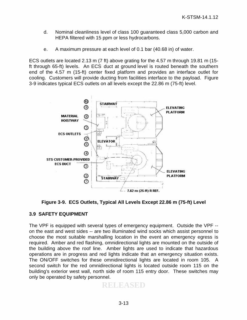
ECS outlets are located 2.13 m (7 ft) above grating for the 4.57 m through 19.81 m (15-ft through 65-ft) levels. An ECS duct at ground level is routed beneath the southernend of the 4.57 m (15-ft) center fixed platform and provides an interface outlet forcooling. Customers will provide ducting from facilities interface to the payload. Figure3-9 indicates typical ECS outlets on all levels except the 22.86 m (75-ft) level.
Figure 3-9. ECS Outlets, Typical All Levels Except 22.86 m (75-ft) Level
3.9 SAFETY EQUIPMENT
The VPF is equipped with several types of emergency equipment. Outside the VPF --on the east and west sides -- are two illuminated wind socks which assist personnel tochoose the most suitable marshalling location in the event an emergency egress isrequired. Amber and red flashing, omnidirectional lights are mounted on the outside ofthe building above the roof line. Amber lights are used to indicate that hazardousoperations are in progress and red lights indicate that an emergency situation exists.The ON/OFF switches for these omnidirectional lights are located in room 105. Asecond switch for the red omnidirectional lights is located outside room 115 on thebuilding's exterior west wall, north side of room 115 entry door. These switches mayonly be operated by safety personnel.
K-STSM-14.1.12
RELEASED
3-14
Inside the VPF, all emergency exits have crash bar alarms installed. Use of any one ofthese exits will transmit a signal to the KSC Launch Control Center Electronics SecuritySystem monitor. In the VPF highbay, Breathing Escape Units are located on each testcell level in boxes marked with green and white stripes. When fuels are present, toxicvapor checks are conducted at the beginning of every shift and at critical pointsthroughout the processing flow to detect hydrazine/fuel leaks. Any repositioning of afueled payload requires a toxic vapor check. Emergency showers and eyewashes areprovided in the VPF hypergolic area and on the test cells at the 4.57 m (15-ft), 7.62 m(25-ft) and 10.67 m (35-ft) levels. Portable eyewash canisters are provided at the13.72 m (45-ft), 16.76 m (55-ft) and 19.81 m (65-ft) levels.
Two emergency stop warning horn push buttons and two test cell alternating current(ac) electrical power receptacle disconnect push buttons are located on each test celllevel except the 22.86 m (75-ft) and ground level. The warning horn activation alertspersonnel to stop work until the nature and resolution of an emergency can bedetermined. In the event of a spill or other type of emergency, activating the ac powerdisconnects will prevent sparks or a potential fire problems with test or monitoringequipment being used in the area. An ac electrical power disconnect push button islocated in room 115.
3.10 MECHANICAL PREPARATIONS FOR PAYLOAD PROCESSING
PGOC will ensure the VPF is properly configured to receive a mission payloadpursuant to Operations and Maintenance Instruction (OMI) E2503, MechanicalPreparations for Payload Processing - VPF.
K-STSM-14.1.12
RELEASED
4-1
SECTION IV
ELECTRICAL SYSTEMS
4.1 FACILITY POWER
All ac electrical power to the VPF is supported by an alternate path. This isaccomplished within the KSC Power Distribution System by a dual feed-loop andreclosure system which can be manually activated if the normal power path isinterrupted. Critical circuits (e.g., fire alarm and platform emergency lights) have anemergency generator (60 kilowatt (kw)) activated by an automatic transfer switch. Testcell circuits can be manually transferred to a portable generator upon request.Generator connections also exist to allow HVAC operations in the event of facilitypower loss. Various receptacles in the VPF are dedicated to CITE and CITE powersupplies and are not available for customer use.
4.1.1 HIGHBAY POWER RECEPTACLES. The highbay east wall has two 277/480-volt (V), 200-ampere (A), 3-phase (Ø), 60 Hertz (Hz) explosion-proof (Xp) receptacles.These receptacles are for use by the canister transporter. The highbay west wall hasone 277/480-V, 100-A, 3-Ø, 60-Hz, Xp receptacle. Forty-five additional Xp 208 Vac and120 Vac receptacles are available near the ground level of the highbay.
4.1.2 AIR LOCK POWER RECEPTACLES. The air lock east wall has two 277/480-V,200-A, 3-Ø, 60-Hz, Xp receptacles. These receptacles are used by the canistertransporter. Additional 208 Vac and 120 Vac Xp receptacles are available near theground level of the air lock.
4.1.3 TEST CELLS POWER RECEPTACLES. Power to both the east and west cellsis distributed the same way. Power is distributed in separate risers for the east andwest cells. The cells 4.57 m through 13.72 m (15- through 45-ft) levels have two120/208-V, 60-A, 3-Ø, 60-Hz, Xp receptacles; seventeen 120-V, 20-A, 1-Ø, 60-Hz, Xpreceptacles; and four 120/208-V, 30-A, 3-Ø, 60-Hz, Xp receptacles. There is also one277/480-V, 100-A, 3-Ø, 60-Hz, Xp receptacle on the 10.67 m (35-ft) level. The 16.76 m(55-ft) level has one 120/208-V, 60-A, 3-Ø, 60-Hz, Xp receptacle; 14 120-V, 20-A, 1-Ø,60-Hz, Xp receptacles; four 120/208-V, 30-A, 3-Ø, 60-Hz, Xp receptacles; one 277/480-V, 200-A, 3-Ø, 60-Hz, Xp; and one 480-V, 60-A, 3-Ø, 60-Hz, Xp (dedicated to CITE)receptacles. The 19.81 m (65-ft) level has 14 120-V, 20-A, 1-Ø, 60-Hz, Xp receptaclesand four 120/208-V, 60-A, 3-Ø, 60-Hz, Xp receptacles. The 22.86 m (75-ft) level has12 120-V, 20-A, 1-Ø, 60-Hz, Xp receptacles; seven 120-V, 30-A, 1-Ø, 60-Hz, Xpreceptacles; and one 120/208-V, 30-A, 3-Ø, 60-Hz, Xp receptacle. Extra circuits arefed to the 19.81 m (65-ft) level for receptacles to the CITE interface terminal distributor(I/F TD) racks, hardware interface modules (HIMs), Video and Data Assembly (V&DA),and the CITE heat exchanger simulator power. Electrical receptacles are generallylocated between 0.61 m (2 ft) and 1.7 m (5 ft 7 in) above the platforms.
K-STSM-14.1.12
RELEASED
4-2
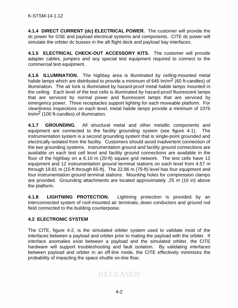
4.1.4 DIRECT CURRENT (dc) ELECTRICAL POWER. The customer will provide thedc power for GSE and payload electrical systems and components. CITE dc power willsimulate the orbiter dc busses in the aft flight deck and payload bay interfaces.
4.1.5 ELECTRICAL CHECK-OUT ACCESSORY KITS. The customer will provideadapter cables, jumpers and any special test equipment required to connect to thecommercial test equipment.
4.1.6 ILLUMINATION. The highbay area is illuminated by ceiling-mounted metalhalide lamps which are distributed to provide a minimum of 645 lm/m2 (60 ft-candles) ofillumination. The air lock is illuminated by hazard-proof metal halide lamps mounted inthe ceiling. Each level of the test cells is illuminated by hazard-proof fluorescent lampsthat are serviced by normal power and fluorescent lamps that are serviced byemergency power. Three receptacles support lighting for each moveable platform. Forcleanliness inspections on each level, metal halide lamps provide a minimum of 1075lm/m2 (100 ft-candles) of illumination.
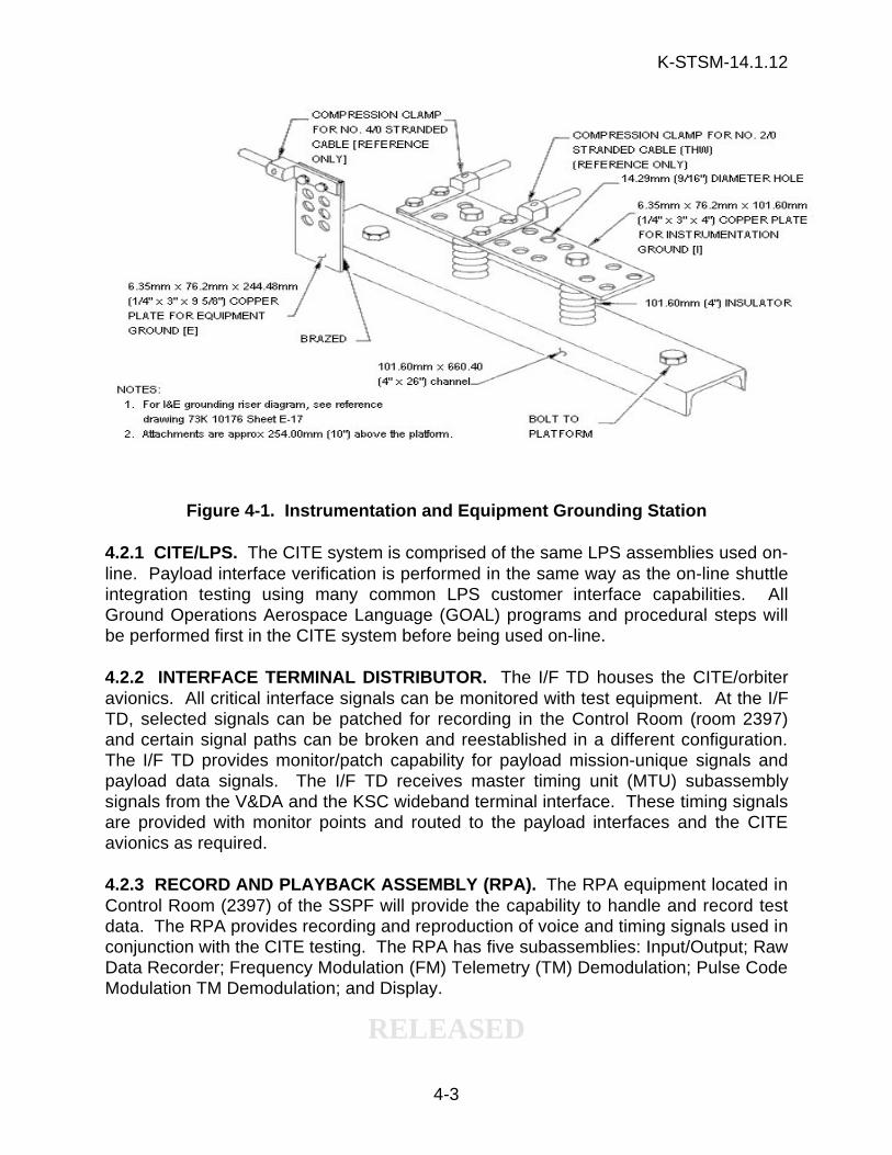
4.1.7 GROUNDING. All structural metal and other metallic components andequipment are connected to the facility grounding system (see figure 4-1). Theinstrumentation system is a second grounding system that is single-point grounded andelectrically isolated from the facility. Customers should avoid inadvertent connection ofthe two grounding systems. Instrumentation ground and facility ground connections areavailable on each test cell level and facility ground connections are available in thefloor of the highbay on a 6.10 m (20-ft) square grid network. The test cells have 12equipment and 12 instrumentation ground terminal stations on each level from 4.57 mthrough 19.81 m (15-ft through 65-ft). The 22.86 m (75-ft) level has four equipment andfour instrumentation ground terminal stations. Mounting holes for compression clampsare provided. Grounding attachments are located approximately .25 m (10 in) abovethe platform.
4.1.8 LIGHTNING PROTECTION. Lightning protection is provided by aninterconnected system of roof-mounted air terminals, down conductors and ground rodfield connected to the building counterpoise.
4.2 ELECTRONIC SYSTEM
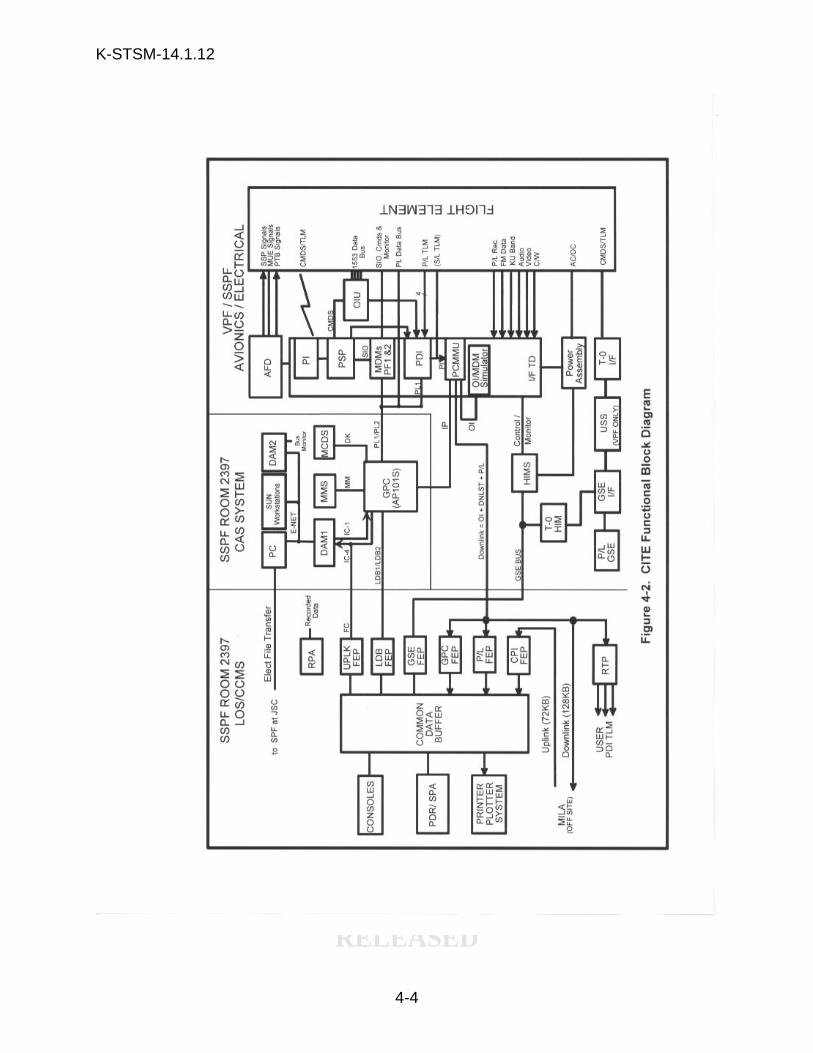
The CITE, figure 4-2, is the simulated orbiter system used to validate most of theinterfaces between a payload and orbiter prior to mating the payload with the orbiter. Ifinterface anomalies exist between a payload and the simulated orbiter, the CITEhardware will support troubleshooting and fault isolation. By validating interfacesbetween payload and orbiter in an off-line mode, the CITE effectively minimizes theprobability of impacting the space shuttle on-line flow.
K-STSM-14.1.12
RELEASED
4-3
Figure 4-1. Instrumentation and Equipment Grounding Station
4.2.1 CITE/LPS. The CITE system is comprised of the same LPS assemblies used on-line. Payload interface verification is performed in the same way as the on-line shuttleintegration testing using many common LPS customer interface capabilities. AllGround Operations Aerospace Language (GOAL) programs and procedural steps willbe performed first in the CITE system before being used on-line.
4.2.2 INTERFACE TERMINAL DISTRIBUTOR. The I/F TD houses the CITE/orbiteravionics. All critical interface signals can be monitored with test equipment. At the I/FTD, selected signals can be patched for recording in the Control Room (room 2397)and certain signal paths can be broken and reestablished in a different configuration.The I/F TD provides monitor/patch capability for payload mission-unique signals andpayload data signals. The I/F TD receives master timing unit (MTU) subassemblysignals from the V&DA and the KSC wideband terminal interface. These timing signalsare provided with monitor points and routed to the payload interfaces and the CITEavionics as required.
4.2.3 RECORD AND PLAYBACK ASSEMBLY (RPA). The RPA equipment located inControl Room (2397) of the SSPF will provide the capability to handle and record testdata. The RPA provides recording and reproduction of voice and timing signals used inconjunction with the CITE testing. The RPA has five subassemblies: Input/Output; RawData Recorder; Frequency Modulation (FM) Telemetry (TM) Demodulation; Pulse CodeModulation TM Demodulation; and Display.
K-STSM-14.1.12
RELEASED
4-4
K-STSM-14.1.12
RELEASED
4-5
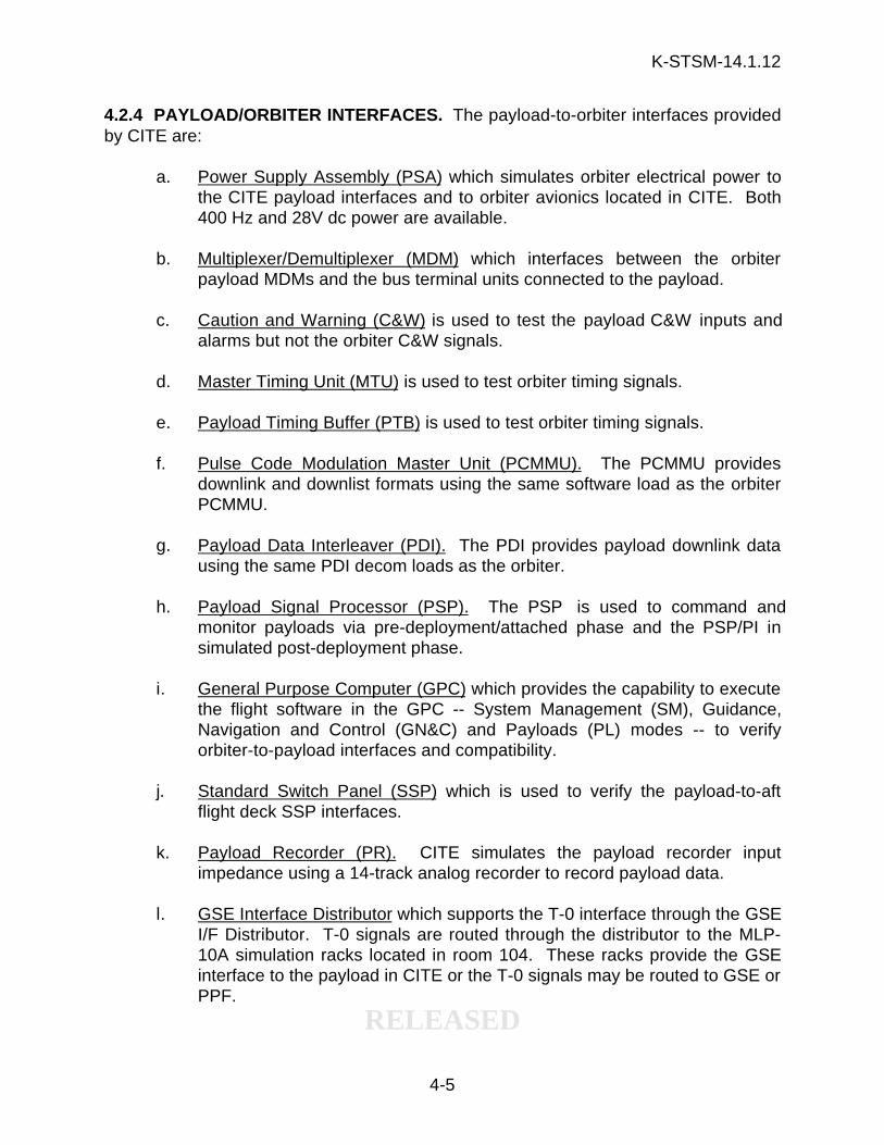
4.2.4 PAYLOAD/ORBITER INTERFACES. The payload-to-orbiter interfaces providedby CITE are:
a. Power Supply Assembly (PSA) which simulates orbiter electrical power tothe CITE payload interfaces and to orbiter avionics located in CITE. Both400 Hz and 28V dc power are available.
b. Multiplexer/Demultiplexer (MDM) which interfaces between the orbiterpayload MDMs and the bus terminal units connected to the payload.
c. Caution and Warning (C&W) is used to test the payload C&W inputs andalarms but not the orbiter C&W signals.
d. Master Timing Unit (MTU) is used to test orbiter timing signals.
e. Payload Timing Buffer (PTB) is used to test orbiter timing signals.
f. Pulse Code Modulation Master Unit (PCMMU). The PCMMU providesdownlink and downlist formats using the same software load as the orbiterPCMMU.
g. Payload Data Interleaver (PDI). The PDI provides payload downlink datausing the same PDI decom loads as the orbiter.
h. Payload Signal Processor (PSP). The PSP is used to command andmonitor payloads via pre-deployment/attached phase and the PSP/PI insimulated post-deployment phase.
i. General Purpose Computer (GPC) which provides the capability to executethe flight software in the GPC -- System Management (SM), Guidance,Navigation and Control (GN&C) and Payloads (PL) modes -- to verifyorbiter-to-payload interfaces and compatibility.
j. Standard Switch Panel (SSP) which is used to verify the payload-to-aftflight deck SSP interfaces.
k. Payload Recorder (PR). CITE simulates the payload recorder inputimpedance using a 14-track analog recorder to record payload data.
l. GSE Interface Distributor which supports the T-0 interface through the GSEI/F Distributor. T-0 signals are routed through the distributor to the MLP-10A simulation racks located in room 104. These racks provide the GSEinterface to the payload in CITE or the T-0 signals may be routed to GSE orPPF.
K-STSM-14.1.12
RELEASED
4-6
m. Special CITE Functions. CITE provides special monitoring and supportfunctions such as breakout distributors, patch panels, test points, andsignal recording capability for:
1) Mission-unique monitor panel
2) Scientific data panel
3) GSE monitor panel
n. Payload Interrogator (PI). CITE provides a PI to command and monitor thepayload in a simulated post-deployment phase.
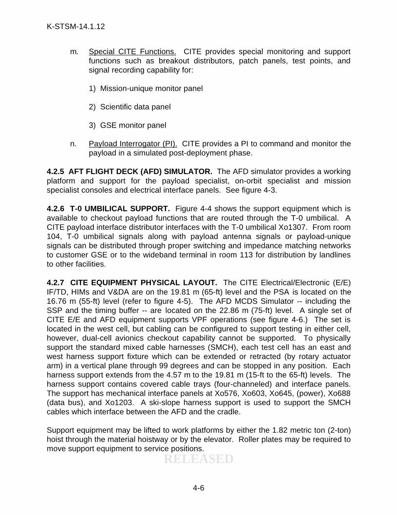
4.2.5 AFT FLIGHT DECK (AFD) SIMULATOR. The AFD simulator provides a workingplatform and support for the payload specialist, on-orbit specialist and missionspecialist consoles and electrical interface panels. See figure 4-3.
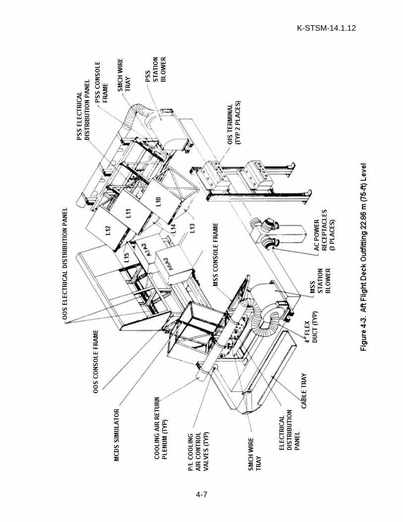
4.2.6 T-0 UMBILICAL SUPPORT. Figure 4-4 shows the support equipment which isavailable to checkout payload functions that are routed through the T-0 umbilical. ACITE payload interface distributor interfaces with the T-0 umbilical Xo1307. From room104, T-0 umbilical signals along with payload antenna signals or payload-uniquesignals can be distributed through proper switching and impedance matching networksto customer GSE or to the wideband terminal in room 113 for distribution by landlinesto other facilities.
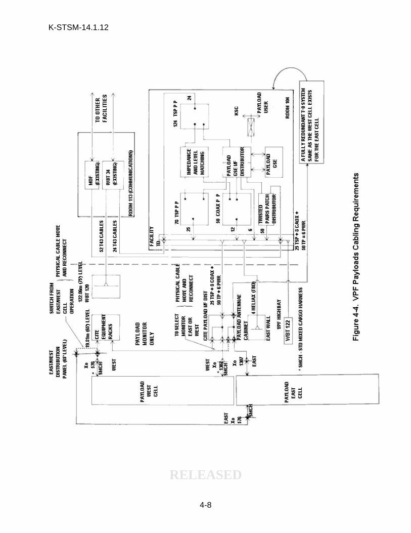
4.2.7 CITE EQUIPMENT PHYSICAL LAYOUT. The CITE Electrical/Electronic (E/E)IF/TD, HIMs and V&DA are on the 19.81 m (65-ft) level and the PSA is located on the16.76 m (55-ft) level (refer to figure 4-5). The AFD MCDS Simulator -- including theSSP and the timing buffer -- are located on the 22.86 m (75-ft) level. A single set ofCITE E/E and AFD equipment supports VPF operations (see figure 4-6.) The set islocated in the west cell, but cabling can be configured to support testing in either cell,however, dual-cell avionics checkout capability cannot be supported. To physicallysupport the standard mixed cable harnesses (SMCH), each test cell has an east andwest harness support fixture which can be extended or retracted (by rotary actuatorarm) in a vertical plane through 99 degrees and can be stopped in any position. Eachharness support extends from the 4.57 m to the 19.81 m (15-ft to the 65-ft) levels. Theharness support contains covered cable trays (four-channeled) and interface panels.The support has mechanical interface panels at Xo576, Xo603, Xo645, (power), Xo688(data bus), and Xo1203. A ski-slope harness support is used to support the SMCHcables which interface between the AFD and the cradle.
Support equipment may be lifted to work platforms by either the 1.82 metric ton (2-ton)hoist through the material hoistway or by the elevator. Roller plates may be required tomove support equipment to service positions.
K-STSM-14.1.12
RELEASED
4-7
K-STSM-14.1.12
RELEASED
4-8

K-STSM-14.1.12
RELEASED
4-9
K-STSM-14.1.12
RELEASED
4-10
Figure 4-6. VPF CITE Equipment Location
4.2.8 INTERFACE TEST PROCEDURES. Before connecting CITE to a payload, theCITE system is validated to ensure proper, safe and compatible operation withpayloads. After the payload is mechanically installed and electrically connected toCITE, a payload interface verification test is performed to validate the interfacesbetween CITE (the simulated orbiter) and the payload. The payload and carrier ownersparticipate in this test. CITE software is provided to test and monitor CITE hardwareprior to and during payload interface testing at CITE.
4.3 AUXILIARY FACILITY INTERFACE POINTS
The north end of the VPF area contains ac power 120/208-V, 100-A, 60-Hz receptaclesalong with portable instrument grade ac power. An interface panel -- located on theeast wall of room 104 -- contains an ac power supply along with an instrument gradepower supply.
K-STSM-14.1.12
RELEASED
4-11
4.4 FUELING/DEFUELING SAFEGUARDS
PGOC will perform power off/on sequences for VPF Highbay hazardous and non-hazardous classified electrical equipment prior to and after payload fueling or defuelingactivities in the VPF East Cell. PGOC will safe all electrical systems in accordancewith the procedures outlined in OMI 2561, 60 Hz Electrical Systems ShutdownProcedure - VPF.

K-STSM-14.1.12
RELEASED
4-12
THIS PAGE INTENTIONALLY LEFT BLANK
K-STSM-14.1.12
RELEASED
5-1
SECTION V
COMMUNICATIONS AND DATA HANDLING
5.1 COMMUNICATIONS
The VPF is serviced by the following administrative and operational communicationssystems: the Operational Intercommunication System-Digital (OIS-D); closed-circuittelevision (CCTV); administrative telephones; range timing signal and count-downindicators; and a public address (PA) system.
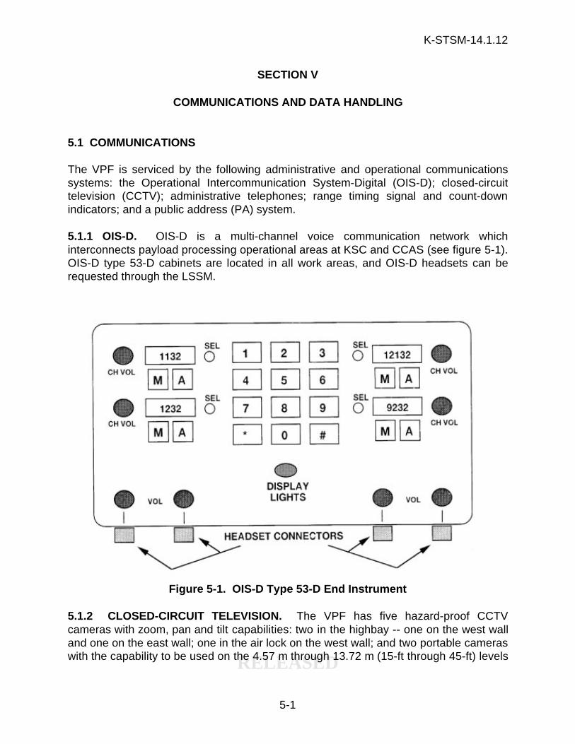
5.1.1 OIS-D. OIS-D is a multi-channel voice communication network whichinterconnects payload processing operational areas at KSC and CCAS (see figure 5-1).OIS-D type 53-D cabinets are located in all work areas, and OIS-D headsets can berequested through the LSSM.
Figure 5-1. OIS-D Type 53-D End Instrument
5.1.2 CLOSED-CIRCUIT TELEVISION. The VPF has five hazard-proof CCTVcameras with zoom, pan and tilt capabilities: two in the highbay -- one on the west walland one on the east wall; one in the air lock on the west wall; and two portable cameraswith the capability to be used on the 4.57 m through 13.72 m (15-ft through 45-ft) levels
K-STSM-14.1.12
RELEASED
5-2
of the test cells. Operations can be monitored at viewer discretion in the OSBconference room as well as other areas with access to the CCTV switching system.
CCTV provides closed-circuit video surveillance and recording of payload processingoperations in the air lock and highbays. CCTV can be monitored and controlled inareas of the OSB, the CITE control room (SSPF room 2397) and the Video RoutingSwitcher Systems (VRSS). A monitor capability also exists in both payload controlrooms in the SAEF-2 Control Facility (M7-1061).
5.1.3 OTHER COMMUNICATIONS. Other forms of communication located in the VPFinclude explosion-proof telephones located in the highbay and air lock. The internal PAsystem is common to both the VPF and OSB. Paging may be inhibited duringhazardous or critical operations. Countdown clocks (displaying Greenwich Mean Timeand range timing) are installed on the east wall of the highbay and on the 19.81 m and22.86 m (65-ft and 75-ft) levels of the test cells.
5.2 DATA HANDLING
Wideband and reradiating antenna systems are available in the VPF to supportpayload element processing requirements. The payload LSSM should be contacted forcurrent data handling capabilities.
5.2.1 WIDEBAND CABLE TRANSMISSION SYSTEM. A wideband terminal distributoris located on the 22.86 m (75-ft) level. CITE signals and payload signals interface atthis distributor and continue to the wideband terminal (WBT) in room 113 and tolandlines to other facilities.
A hardline communications capability is provided to link the payloads in the VPF withremote GSE located at the PPFs. The hardline communications system consists ofdata line drivers and receivers which provide the necessary cable compensation fordigital data transmission of up to 128 KBPS (BiØ-L) or 256 KBPS (NRZ-L) to and fromthe PPFs. These data lines meet the RS-422 standards. The WBT is designed topresent the same signal characteristics as those found at the VPF and pad. The signalcharacteristics for a wideband circuit at KSC references an analog or digital signalbetween 30 Hz and 4.5 MHz at 1.0 Vp-p +/- 0.2 terminated into a 124 ohms balancedload. Twisted pair copper unequipped lines are also available to support customermodems.
Inter-range instrumentation group (IRIG-B), IRIG-E and IRIG-H timing is available on alllevels of the test cells and floor. Cabling is routed from the communications room tothe test cells and travels up a riser to each cell. A timing distributor box is available onall levels. Timing signals terminate in a connecting block.
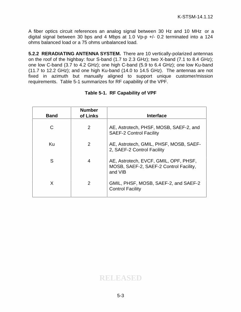
K-STSM-14.1.12
RELEASED
5-3
A fiber optics circuit references an analog signal between 30 Hz and 10 MHz or adigital signal between 30 bps and 4 Mbps at 1.0 Vp-p +/- 0.2 terminated into a 124ohms balanced load or a 75 ohms unbalanced load.
5.2.2 RERADIATING ANTENNA SYSTEM. There are 10 vertically-polarized antennason the roof of the highbay: four S-band (1.7 to 2.3 GHz); two X-band (7.1 to 8.4 GHz);one low C-band (3.7 to 4.2 GHz); one high C-band (5.9 to 6.4 GHz); one low Ku-band(11.7 to 12.2 GHz); and one high Ku-band (14.0 to 14.5 GHz). The antennas are notfixed in azimuth but manually aligned to support unique customer/missionrequirements. Table 5-1 summarizes for RF capability of the VPF.
Table 5-1. RF Capability of VPF
BandNumberof Links Interface
C 2 AE, Astrotech, PHSF, MOSB, SAEF-2, andSAEF-2 Control Facility
Ku 2 AE, Astrotech, GMIL, PHSF, MOSB, SAEF-2, SAEF-2 Control Facility
S 4 AE, Astrotech, EVCF, GMIL, OPF, PHSF,MOSB, SAEF-2, SAEF-2 Control Facility,and VIB
X 2 GMIL, PHSF, MOSB, SAEF-2, and SAEF-2Control Facility
K-STSM-14.1.12
RELEASED
5-4
THIS PAGE INTENTIONALLY LEFT BLANK
K-STSM-14.1.12
RELEASED
6-1
SECTION VI
FACILITY DESCRIPTION SUMMARY
6.1 SAFETY
a. Automatic fire detection system Heat-activated deviceslocated in ceilings,infrared and ultra-violetinstalled on walls and testcells
b. Manually-operated fire alarms Pullboxes located in airlock (101), highbay (102),oven (103), and outside
c. Fire protection system Water deluge system andmanual extinguishers(CO2)
d. Hypergol exhaust system Highbay
e. Hypergol drain system Below test cells in highbay
f. Scrubber system 4.7 m thru 19.81 m (15-ftthrough 65-ft) levels withaspirators
g. Safety equipment Safety showers, eyewashfountains, audio-visualwarning signals, hazard-proof exit lights,emergency breathing airapparatus
6.2 FLOOR SPACE
VPF 1207.7 m2 (13,000 ft2)ofusable floor space
a. Air lock 12.8 m x 22.88 m (42 ftwide x 75 ft) long
b. Highbay 22.88 m x 45.75 m (75 ftwide x 150 ft) long
K-STSM-14.1.12
RELEASED
6-2
c. Operations Support Building 929 m2 (10,000 ft2)and Annex
d. RTG-F 276 m2 (2,967 ft 2)
6.3 CEILING HEIGHT
a. Air lock 22.73 m (74 ft 7 in)
b. Highbay 32.00 m (105 ft)
6.4 EQUIPMENT ENTRY (CLEAR)
a. Air lock Rolling equipment door7.55 m x 21.66 m (24 ft 9in wide x 71 ft 1/8 in) high
b. Highbay Vertical leaf door 11.58 mx 21.77 m (38 ft wide x 71ft 4-1/2 in) high
6.5 CRANES
a. Air lock One 9.08 metric ton (10-ton) monorail
b. Highbay One 22.68 metric ton (25-ton) bridge crane
One 10.89 metric ton (12-ton) bridge crane
c. 22.86 m (75 ft) level test cell 1.8 metric ton (2 ton) hoist
6.6 HOOK HEIGHTS
a. Air lock 20.02 m (65 ft 8 in)
b. Highbay 28.34 m (93 ft) 12 ton
28.65 m (94 ft) 25 ton
K-STSM-14.1.12
RELEASED
6-3
6.7 SYSTEMS AND EQUIPMENT
a. Pneumatics Compressed air at 0-9.24bars (0-135 psig) on alllevels of test cells except22.86 m (75-ft) level; 9.24and 5.52 bars (135 psigand 80 psig) in highbayand air lock
b. C/A exhaust system Air tools used to retractplatforms are serviced bya hose reel connected toan oil supply. The exhaustis contained and routedthrough an outside ventsystem
c. Vacuum system Air lock, highbay, all testcell levels, personnel entryroom, locker room, andequipment air lock
d. Gaseous Nitrogen 413.72/206.86 bars(6000/3000 psig), 51.72bars (750 psig), 3.45 bars(50 psig) to the test cell
e. Gaseous Helium 51.72 bars (750 psig) tothe test cell
f. Breathing air 2400 psig at 14.57 m (15ft), 10.67 m (35 ft), and16.76 m (55 ft) test celllevels
6.8 TEMPERATURE/HUMIDITY
All operational areas 21.7° +/- 3.3°C (71° +/-6°F)/55 percent relativehumidity
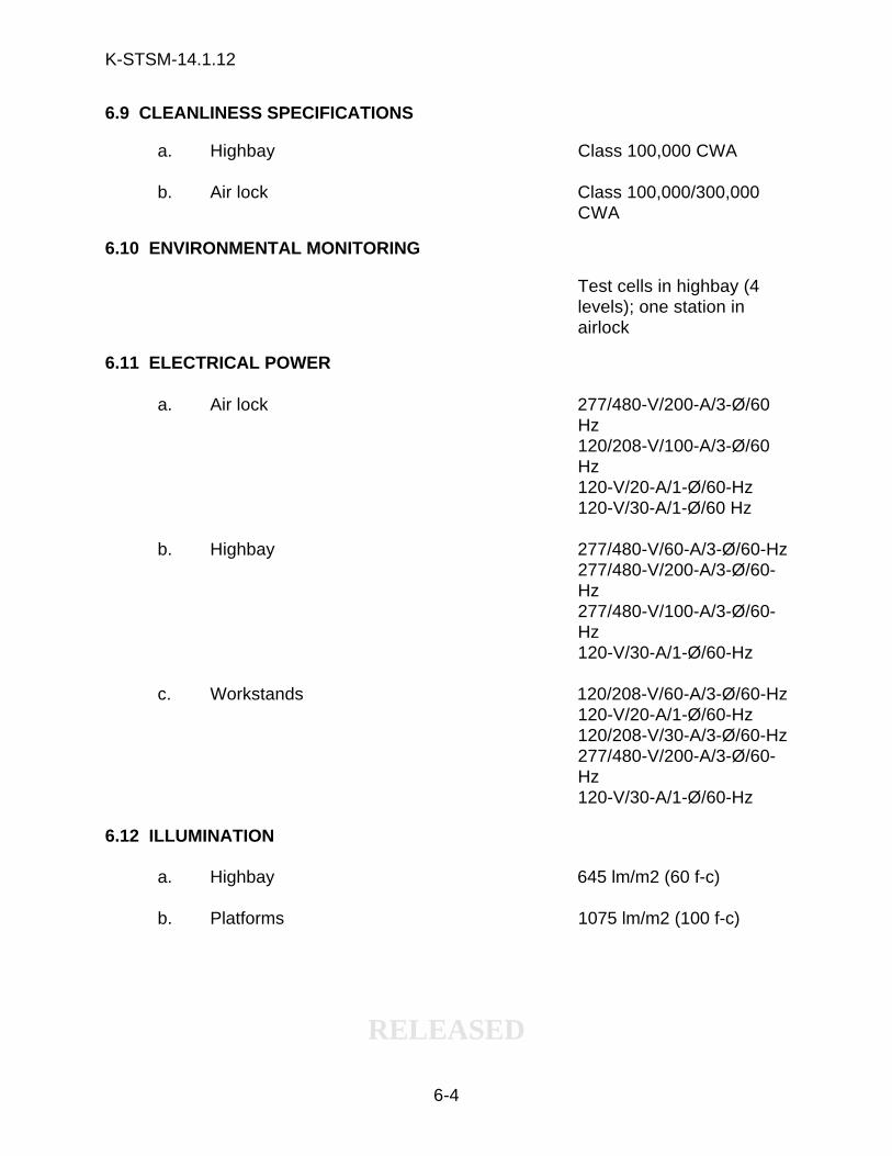
K-STSM-14.1.12
RELEASED
6-4
6.9 CLEANLINESS SPECIFICATIONS
a. Highbay Class 100,000 CWA
b. Air lock Class 100,000/300,000CWA
6.10 ENVIRONMENTAL MONITORING
Test cells in highbay (4levels); one station inairlock
6.11 ELECTRICAL POWER
a. Air lock 277/480-V/200-A/3-Ø/60Hz120/208-V/100-A/3-Ø/60Hz120-V/20-A/1-Ø/60-Hz120-V/30-A/1-Ø/60 Hz
b. Highbay 277/480-V/60-A/3-Ø/60-Hz277/480-V/200-A/3-Ø/60-Hz277/480-V/100-A/3-Ø/60-Hz120-V/30-A/1-Ø/60-Hz
c. Workstands 120/208-V/60-A/3-Ø/60-Hz120-V/20-A/1-Ø/60-Hz120/208-V/30-A/3-Ø/60-Hz277/480-V/200-A/3-Ø/60-Hz120-V/30-A/1-Ø/60-Hz
6.12 ILLUMINATION
a. Highbay 645 lm/m2 (60 f-c)
b. Platforms 1075 lm/m2 (100 f-c)
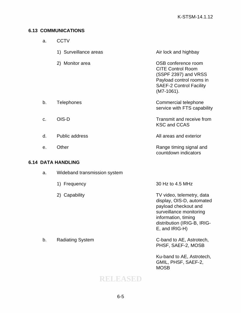
K-STSM-14.1.12
RELEASED
6-5
6.13 COMMUNICATIONS
a. CCTV
1) Surveillance areas Air lock and highbay
2) Monitor area OSB conference roomCITE Control Room(SSPF 2397) and VRSSPayload control rooms inSAEF-2 Control Facility(M7-1061).
b. Telephones Commercial telephoneservice with FTS capability
c. OIS-D Transmit and receive fromKSC and CCAS
d. Public address All areas and exterior
e. Other Range timing signal andcountdown indicators
6.14 DATA HANDLING
a. Wideband transmission system
1) Frequency 30 Hz to 4.5 MHz
2) Capability TV video, telemetry, datadisplay, OIS-D, automatedpayload checkout andsurveillance monitoringinformation, timingdistribution (IRIG-B, IRIG-E, and IRIG-H)
b. Radiating System C-band to AE, Astrotech,PHSF, SAEF-2, MOSB
Ku-band to AE, Astrotech,GMIL, PHSF, SAEF-2,MOSB
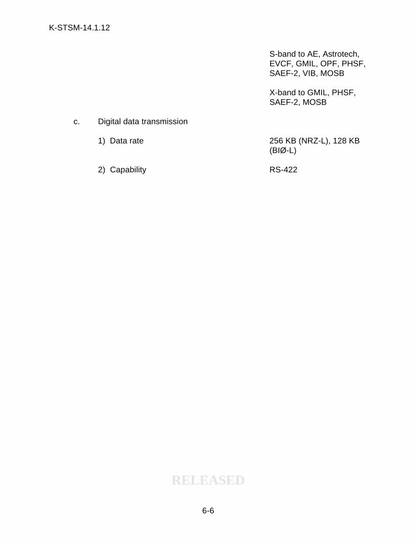
K-STSM-14.1.12
RELEASED
6-6
S-band to AE, Astrotech,EVCF, GMIL, OPF, PHSF,SAEF-2, VIB, MOSB
X-band to GMIL, PHSF,SAEF-2, MOSB
c. Digital data transmission
1) Data rate 256 KB (NRZ-L), 128 KB(BIØ-L)
2) Capability RS-422
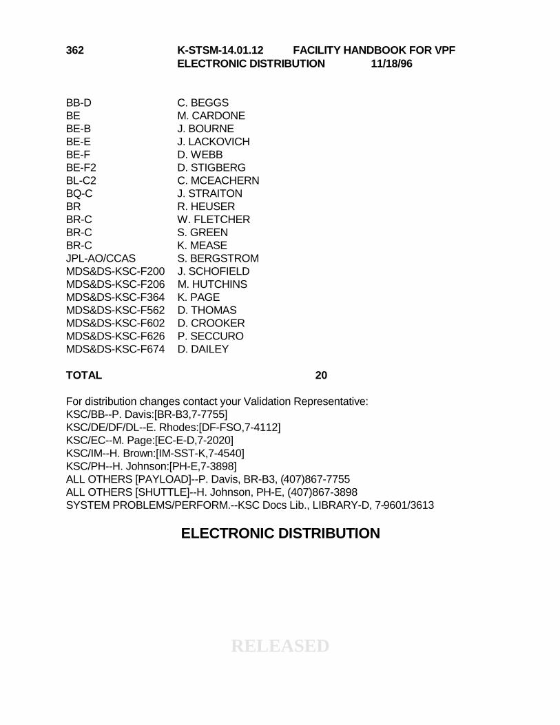
RELEASED
362 K-STSM-14.01.12 FACILITY HANDBOOK FOR VPFELECTRONIC DISTRIBUTION 11/18/96
BB-D C. BEGGSBE M. CARDONEBE-B J. BOURNEBE-E J. LACKOVICHBE-F D. WEBBBE-F2 D. STIGBERGBL-C2 C. MCEACHERNBQ-C J. STRAITONBR R. HEUSERBR-C W. FLETCHERBR-C S. GREENBR-C K. MEASEJPL-AO/CCAS S. BERGSTROMMDS&DS-KSC-F200 J. SCHOFIELDMDS&DS-KSC-F206 M. HUTCHINSMDS&DS-KSC-F364 K. PAGEMDS&DS-KSC-F562 D. THOMASMDS&DS-KSC-F602 D. CROOKERMDS&DS-KSC-F626 P. SECCUROMDS&DS-KSC-F674 D. DAILEY
TOTAL 20
For distribution changes contact your Validation Representative:KSC/BB--P. Davis:[BR-B3,7-7755]KSC/DE/DF/DL--E. Rhodes:[DF-FSO,7-4112]KSC/EC--M. Page:[EC-E-D,7-2020]KSC/IM--H. Brown:[IM-SST-K,7-4540]KSC/PH--H. Johnson:[PH-E,7-3898]ALL OTHERS [PAYLOAD]--P. Davis, BR-B3, (407)867-7755ALL OTHERS [SHUTTLE]--H. Johnson, PH-E, (407)867-3898SYSTEM PROBLEMS/PERFORM.--KSC Docs Lib., LIBRARY-D, 7-9601/3613
ELECTRONIC DISTRIBUTION
RELEASED
362 K-STSM-14.01.12 FACILITY HANDBOOK FOR VPFHARD COPY DISTRIBUTION 11/18/96
45 SPW/SESE W. BREYER SPACEHABAC-PRO N. TALLUTO ATTN: W. SPRADLINBE-B2 LIBRARY 620 MAGELLAN RD.BL D. BRAGDON CAPE CANAVERAL, FLBL-D A. MACKEY 32920BOC-323 S. MCGOVERNBR-C LIBRARY 25BR-D1 LIBRARYCG-LSO-1 D. BRUSEDE H. HILTONDE-FLS R. EVANSEI-F-A W. HIGGINSEI-F-B R. WOODSFORMS WAREHOUSE 30IM-SPS M. JONESJPL-AO/CCAS S. BERGSTROM 2LIBRARY-D KSC LIB DOCS 2MDA-CCAS D. MACLEANMDAC-HSV W. TURNERMDS&DS-KSC-F054 K. BERINGER 2MDS&DS-KSC-F102 J. NICHOLSMDS&DS-KSC-F364 J. SALAMONE 5MDS&DS-KSC-F376 LIBRARY 10MDS&DS-KSC-F546 W. SMITHMDS&DS-KSC-F658 TDC LIBRARYMMC-AF E. O'CONNORPK-D1 LIBRARYUSK-038 LIBRARYLERC-60-3 A. LILLY
TOTAL 99
For distribution changes contact your Validation Representative:KSC/BB--P. Davis:[BR-B3,7-7755]KSC/DE/DF/DL--E. Rhodes:[DF-FSO,7-4112]KSC/EC--M. Page:[EC-E-D,7-2020]KSC/IM--H. Brown:[IM-SST-K,7-4540]KSC/PH--H. Johnson:[PH-E,7-3898]ALL OTHERS [PAYLOAD]--P. Davis, BR-B3, (407)867-7755ALL OTHERS [SHUTTLE]--H. Johnson, PH-E, (407)867-3898SYSTEM PROBLEMS/PERFORM.--KSC Docs Lib., LIBRARY-D, 7-9601/3613
HARD COPY DISTRIBUTION
Related Documents