1 CENTRE DE RECHERCHES EN PHYSIQUE DES PLASMAS ASSOCIATION EURATOM –CONFEDERATION SUISSE CRPP-Technologie de la Fusion, CH 5232 Villigen PSI EDIPO Test Facility User Specification INT 213/15 EDIPO/SULTAN Team Pierluigi Bruzzone, Boris Stepanov, Rainer Wesche, Kamil Sedlak, Davide Uglietti June 2015

Welcome message from author
This document is posted to help you gain knowledge. Please leave a comment to let me know what you think about it! Share it to your friends and learn new things together.
Transcript
1
CENTRE DE RECHERCHES EN PHYSIQUE DES PLASMAS
ASSOCIATION EURATOM –CONFEDERATION SUISSE
CRPP-Technologie de la Fusion, CH 5232 Villigen PSI
EDIPO Test Facility User Specification
INT 213/15
EDIPO/SULTAN Team Pierluigi Bruzzone, Boris Stepanov, Rainer Wesche, Kamil Sedlak, Davide Uglietti
June 2015
2
Table of Content
1. Introduction
2. DC Magnet System
3. Pulsing Coils 4. Bipolar Power Supply for Pulsing Coils 5. Vertical Access
6. Sample Dimensions
6.1 LTS Sample 6.2 HTS Sample
7. Operating Range
8. Cryogenic System
9. Data Acquisition System and Software
10. Instrumentation
10.1 Sensors with Four Wires 10.2 Sensors with Two Wires
11. Sample Condition and Certificates
12. Summary of Key Items to be observed

3
1. Introduction
The EDIPO (acronym for European Dipole) test facility is the second major facility (next to SULTAN) for testing and evaluating high-current forced flow superconductors for the prospective generation of fusion magnets. Located at Paul Scherrer Institut (PSI) in Villigen, Switzerland, the facility was erected during 2011-2013, fully commissioned in April 2015 and is offered to the worldwide cooperation for the development of the high-current superconductors operating at high background magnetic field. In the facility, prototype and R&D conductor samples can be tested over a wide range of operating conditions. The typical studies include experiments on conductor critical current and current sharing temperature, AC losses and the conductor fatigue effects.
The EDIPO test facility consists of the main DC coils providing the background field up to 12.35 T (at 17.2 kA operating current), the AC dipole coils applying the pulsing field to the conductor up to ±0.52 T (±500 A AC power supply) and the superconducting transformer which allows supply the conductor current up to 100 kA.
The EDIPO test facility is applicable to conduct the experiments on LTS conductors and HTS conductors as well. In case of HTS sample, the operating temperature can be extended up to 50 K using the HTS adapter (to limit the heat flow to the transformer) and the counter-flow heat exchanger to re-cool the helium flow return to the cryo-plant.
2. DC Magnet System
In EDIPO the background magnetic field is generated by the DC superconducting coils (tilted heads race-track coils). The coils, wound with use of Nn3Sn cable-in-conduit conductors, are located in a vacuum tank and are cooled by forced flow supercritical helium. To enhance the field quality and intensity in the central bore (sample test well), an iron yoke is used, made by a stack of soft iron laminated sheets. The yoke encloses the coils and it is itself enclosed in a 35 mm thick cylinder, made with high strength austenitic steel, which has the own cooling circuit to provide the required cool-down and warm-up of the full assembly.
The layout of EDIPO magnet system installed inside the vacuum tank is shown in Figure 1 left; and Figure 1 right illustrates the components of the magnet system. The field profile at full current is measured by sliding calibrated Hall sensors along the axis of the test well. The peak field was measured to be 12.35 T at 17.2 kA, compared to 12.4 T from the field computations. At low currents, the large amount of cold iron causes both a reduction of the field uniformity and a nonlinear current-field relationship. At full 17.2 kA current, the ±1% homogenous field length is at ≈900 mm length, Figure 2. The ±0.5% homogeneous length is at 680 mm length (12.3 T) and 580 mm length (6 T).
3. AC Coils
A set of saddle-shaped copper coils located in the bore of the DC magnets around the test well, generates a pulsed field transverse to both the sample axis and the background DC magnetic field as illustrated in Figure 3. The pulse coils are cooled indirectly with supercritical helium though attached copper pipes. To ensure that the coils are not overheating, a maximum power and pulse duration must not be exceeded. The maximum duration of the pulsed field depends on the AC field (AC current) amplitude, AC field frequency and on the DC background magnetic field; the coolant outlet temperature must not exceed 25 K for a short time in order not to cause a thermal shock in the cryo-plant. The main parameters of the pulse coils are summarized in the Table 1.

4
Figure 1 Layout of EDIPO magnet system (left) and its components (right)
Figure 2 Normalized field uniformity in EDIPO, compared to SULTAN
5
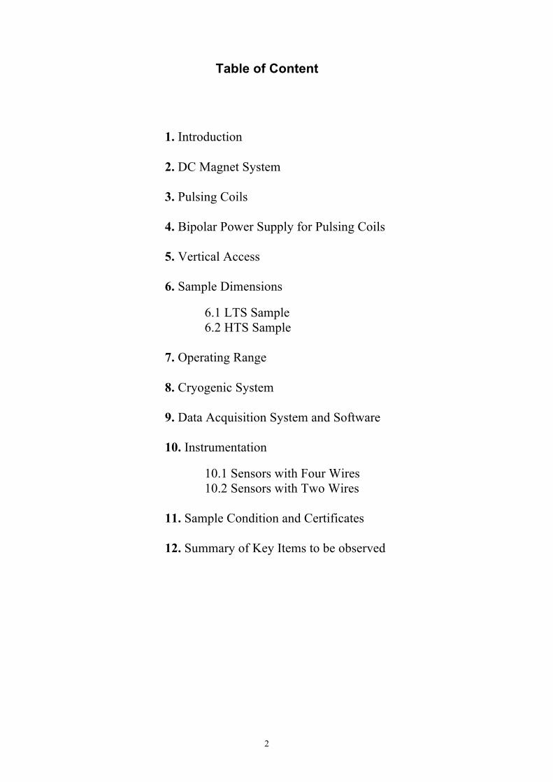
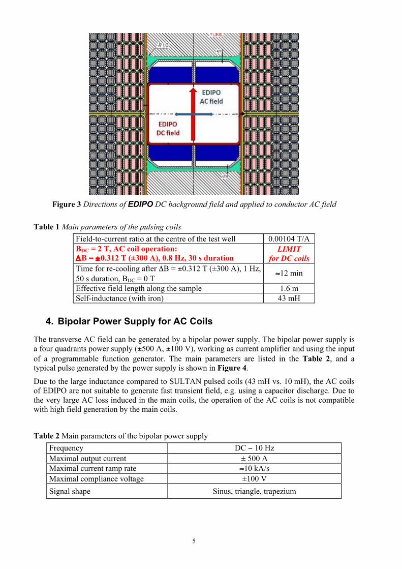
Figure 3 Directions of EDIPO DC background field and applied to conductor AC field
Table 1 Main parameters of the pulsing coils
Field-to-current ratio at the centre of the test well 0.00104 T/A BDC = 2 T, AC coil operation: ΔB = ±0.312 T (±300 A), 0.8 Hz, 30 s duration
LIMIT for DC coils
Time for re-cooling after ΔB = ±0.312 T (±300 A), 1 Hz, 50 s duration, BDC = 0 T
≈12 min
Effective field length along the sample 1.6 m Self-inductance (with iron) 43 mH
4. Bipolar Power Supply for AC Coils
The transverse AC field can be generated by a bipolar power supply. The bipolar power supply is a four quadrants power supply (±500 A, ±100 V), working as current amplifier and using the input of a programmable function generator. The main parameters are listed in the Table 2, and a typical pulse generated by the power supply is shown in Figure 4.
Due to the large inductance compared to SULTAN pulsed coils (43 mH vs. 10 mH), the AC coils of EDIPO are not suitable to generate fast transient field, e.g. using a capacitor discharge. Due to the very large AC loss induced in the main coils, the operation of the AC coils is not compatible with high field generation by the main coils.
Table 2 Main parameters of the bipolar power supply
Frequency DC − 10 Hz Maximal output current ± 500 A Maximal current ramp rate ≈10 kA/s Maximal compliance voltage ±100 V Signal shape Sinus, triangle, trapezium

6
Figure 4 Typical pulse generated by the four quadrants AC power supply (sinus mode).
5. Vertical Access
Short, straight conductor samples are inserted from the top of the facility through a vertical test well into the high field region of EDIPO test facility. The test well is a rectangular pipe with inner dimensions similar to SULTAN test facility; the inner corners are 3 mm rounded. Due to distortions and deformations of the rectangular pipe during manufacture and assembly of the AC coils, the actual free bore for insertion of a long sample is smaller than in SULTAN: to maintain an insertion gap of 1 mm around the sample, the sample cross section in EDIPO must be 89 mm x 138 mm (compared to 92 mm x 142 mm in SULTAN). Its separate vacuum permits insertion and removal of the sample without warming-up or breaking the vacuum of the main vessel, in which the magnet system is located. The insertion unit consists of a telescope-like movable chamber located on top of the facility, a superconducting transformer generating currents up to 100 kA in the sample and the test conductor assembly. The vertical position of the sample can be adjusted by means of steel extenders, between the flange of the transformer unit and the main flange of the vacuum vessel, thus different sections of the sample, including the bottom joint, can be placed into the high field region. Four extenders of 40, 160, 330, and 670 mm length are available. They can be stacked to yield various lengths; however a total of 830 mm should not be exceeded (Figure 5).

7
Figure 5 Position of sample without (left) and with extender (right)
6. Sample Configuration and Dimensions
The sample configuration consists of two straight conductor sections, which are joined at one end at the bottom and clamped between the two terminals of the 100 kA superconducting transformer at the other end in case of LTS sample or clamped between the two terminals of the 100 kA HTS adapter in case of HTS sample, Figures 6a and 6b. For small conductors (round ∅ ≤ 20 mm or rectangular with thickness of ≤ 20 mm) the bottom joint may be replaced by a U-bend (hair-pin configuration), Figure 6c.
Figures 6d and 6e illustrate the final sample layout of LTS sample and HTS sample connected to the HTS adapter, ready for installation in EDIPO test facility. The corners along the sample assembly must be non-metallic, sliding along the surface of stainless sample test well and rounded with radius of >5 mm.

8
Figure 6a LTS sample upper terminations (facing the transformer) with helium pipes
Figure 6b HTS sample upper terminations with piping and terminations of HTS adapter (left)
Figure 6c Bottom U-bend for small conductors (left) and bottom joint (right)

9
Figure 6d LTS sample layout
Figure 6e HTS sample layout
6.1 LTS Sample
The overall length of the LTS sample including the two copper terminals at its top and the clamps at the bottom joint must not exceed (3605.0 ± 0.5) mm, same as SULTAN. The terminals must be at least 500 mm long. In order to avoid that the sample gets stuck in the test well during lowering and lifting, its outer cross sectional dimensions, including the clamping system and the insulation, must be (89.0 ± 0.5) mm x (138.0 ± 0.5) mm.
The four faces must be flat and must extend (without interruption) from the lower end of the bottom joint up to 800 mm below the upper end of the copper terminals. The cross sectional dimensions of the terminal block of the LTS samples to be connected with the transformer unit must be 100.0 ± 0.5 mm wide and 100 +1/- 3 mm thick.
The sample assembly must be absolutely straight to be lowered into the test well; the surfaces of the sample terminals and bottom joint have to be aligned with the mechanical structure around the conductors. The alignment must be such that the horizontal deviation from the vertical axis is less than 2 mm at the bottom of the sample. Figure 7 specifies the required LTS sample lengths, dimensions of terminations with allowed tolerances and position of background magnetic field (no specific requirements for the bottom joint length).
6.2 HTS Sample
In case of HTS sample, the upper terminals must match the interface of the adapter (the bolted connection HTS terminal to HTS adapter enters the test well and must be 89 mm x 138 mm in

10
cross-section. The required lengths and position of background field are shown in Figure 8; the terminals of HTS sample must be 300 mm long.
Figure 7 LTS sample, requirements to lengths and terminations
Figure 8 HTS sample, requirements to lengths and terminations
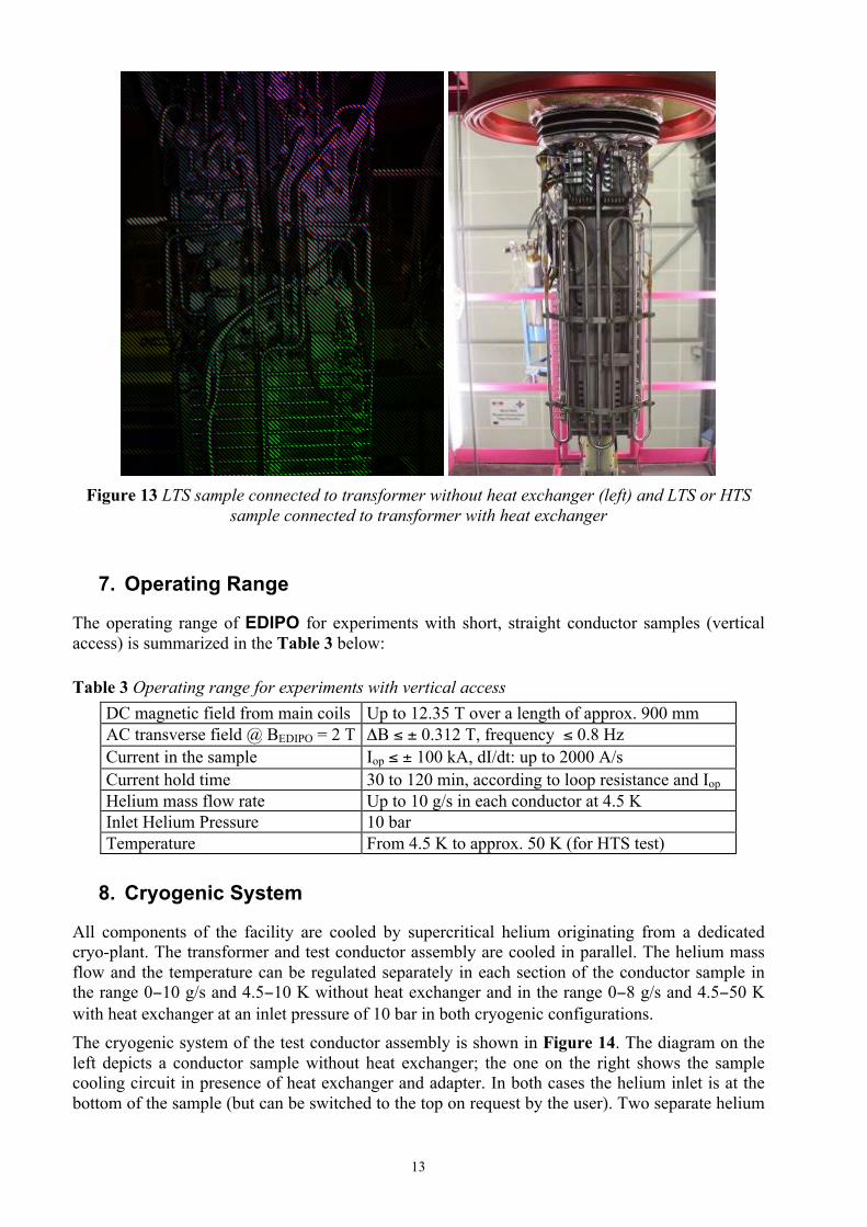
The HTS adapter and its connecting interface to the HTS sample with surrounding mechanical structure are shown in Figure 9 and Figure 10 correspondingly. The each termination of HTS sample must fit a window 64 mm x 41 mm with space of 20 mm between the sample terminations. Figure 12 shows the requirements and allowable tolerances on terminations of HTS sample. Figure 11 shows the connection of the HTS sample to the adapter. Photographs of the copper terminals of the transformer are shown in Figure 12. Figure 13 shows the connection of sample without heat exchanger (only LTS sample) and with heat exchanger (HTS or LTS samples).
The connection of the HTS termination to the adapter is done at CRPP using indium wires and bolted clamps, see Figures 6b and 9. To do the connection, the two HTS conductor terminations

11
must be temporarily moved apart, about 2mm. The clamping system of the HTS sample is loosened during this operation.
The short conductor sample and the secondary winding of the superconducting transformer form a closed loop with low self-inductance L. The total resistance of the loop, including the sample-to-transformer connections and the bottom joint (if present), must be less than 5⋅10-9 Ω in order to allow the transformer to achieve a high current (up to 100 kA) and sustain it over long periods of time. Higher loop resistance, e.g. for HTS sample with the adapter, may limit the range of operation of the transformer, both the maximum current and the time when high current is kept constant.
Figure 9 HTS adapter for the HTS sample
Figure 10 Interface of HTS adapter to HTS sample

12
Figure 11 HTS sample termination requirements
Figure 12 Copper terminals of the transformer
13
Figure 13 LTS sample connected to transformer without heat exchanger (left) and LTS or HTS
sample connected to transformer with heat exchanger
7. Operating Range
The operating range of EDIPO for experiments with short, straight conductor samples (vertical access) is summarized in the Table 3 below: Table 3 Operating range for experiments with vertical access
DC magnetic field from main coils Up to 12.35 T over a length of approx. 900 mm AC transverse field @ BEDIPO = 2 T ΔB ≤ ± 0.312 T, frequency ≤ 0.8 Hz Current in the sample Iop ≤ ± 100 kA, dI/dt: up to 2000 A/s Current hold time 30 to 120 min, according to loop resistance and Iop Helium mass flow rate Up to 10 g/s in each conductor at 4.5 K Inlet Helium Pressure 10 bar Temperature From 4.5 K to approx. 50 K (for HTS test)
8. Cryogenic System
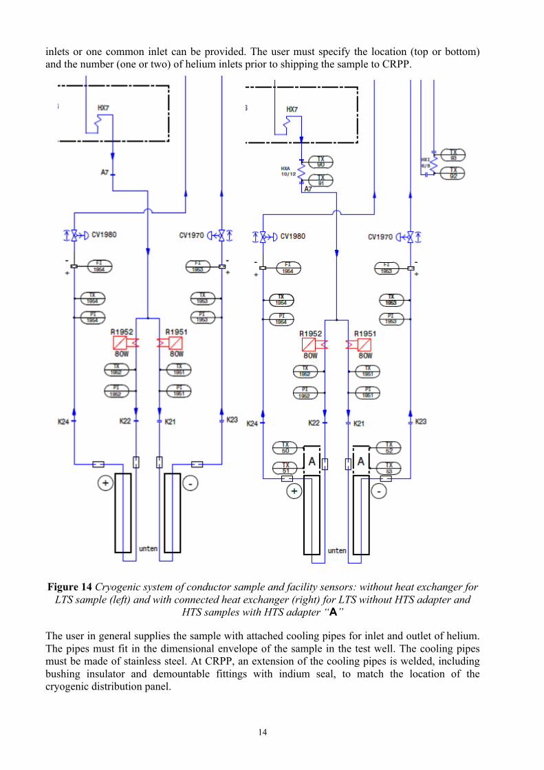
All components of the facility are cooled by supercritical helium originating from a dedicated cryo-plant. The transformer and test conductor assembly are cooled in parallel. The helium mass flow and the temperature can be regulated separately in each section of the conductor sample in the range 0−10 g/s and 4.5−10 K without heat exchanger and in the range 0−8 g/s and 4.5−50 K with heat exchanger at an inlet pressure of 10 bar in both cryogenic configurations. The cryogenic system of the test conductor assembly is shown in Figure 14. The diagram on the left depicts a conductor sample without heat exchanger; the one on the right shows the sample cooling circuit in presence of heat exchanger and adapter. In both cases the helium inlet is at the bottom of the sample (but can be switched to the top on request by the user). Two separate helium
14
inlets or one common inlet can be provided. The user must specify the location (top or bottom) and the number (one or two) of helium inlets prior to shipping the sample to CRPP.
Figure 14 Cryogenic system of conductor sample and facility sensors: without heat exchanger for LTS sample (left) and with connected heat exchanger (right) for LTS without HTS adapter and
HTS samples with HTS adapter “A”
The user in general supplies the sample with attached cooling pipes for inlet and outlet of helium. The pipes must fit in the dimensional envelope of the sample in the test well. The cooling pipes must be made of stainless steel. At CRPP, an extension of the cooling pipes is welded, including bushing insulator and demountable fittings with indium seal, to match the location of the cryogenic distribution panel.

15
There are six power supplies for heaters available in SULTAN, which provide a maximum power of 120 W (Umax = 52 V, Imax = 10 A). Two of them belong to the facility ohmic heaters (R1951 and R1952), which control the coolant temperature for each section of the conductor assembly. The remaining four power supplies with corresponding feeders can be used for user specific heaters attached to the sample. The CRPP staff should be contacted if special arrangements for heaters of the user are required. Four capillary tubes and feedthroughs are available to the users for differential pressure measurements. Connecting the copper terminals and the instrumentation wires as well as flushing and evacuating the cryogenic lines and lowering the sample into EDIPO test well can be completed within one day. Cooling the sample to cryogenic temperatures lasts an additional two days. Approximately the same time is required to warm-up the sample and to remove it from the test well at the end of the experimental period.
9. Data Acquisition System and Software
The Data Acquisition System (DAS) can accommodate up to 128 channels, 25 channels of them are reserved for the instrumentation in EDIPO (Table 4). On-line visualisation of the experiment and data recording run under the program „Lab View”. The on-line visualization and recording of the data is possible for sampling rates up to 35 Hz depending on the visualization options and on the number of recorded signals. The generated data can be stored in (*.dat) file with the names of columns. Table 4 Channels reserved for the EDIPO instrumentation
No. Signals Measured Physical Parameter (Unit) 1 I_18ka P.S. Current of EDIPO DC magnet for background field setting (A) 2 I_Trafo_Primär Transformer primary current (A) 3 I_Trafo Sekundär Transformer secondary current (kA) 4 P.S. EEI (U) Voltage applied to the pulse coils (V) 5 P.S. EEI (I) Current applied to the pulse coils (A) 6 TX1951 Helium inlet temperature, negative conductor section (K) 7 TX1952 Helium inlet temperature, positive conductor section (K) 8 TX1953 Helium outlet temperature, negative conductor section (K) 9 TX1954 Helium outlet temperature, positive conductor section (K) 10 PI1951 Helium inlet pressure, negative conductor section (bar) 11 PI1952 Helium inlet pressure, positive conductor section (bar) 12 PI1953 Helium outlet pressure, negative conductor section (bar) 13 PI1954 Helium outlet pressure, positive conductor section (bar) 14 FI1953 Helium mass flow rate, negative conductor section (g/s) 15 FI1954 Helium mass flow rate, positive conductor section (g/s) 16 R1951 Heater current, negative conductor section (A) 17 R1952 Heater current, positive conductor section (A) 18 TX50 HTS sample/adapter connection, positive side (K) 19 TX51 HTS sample/adapter connection, positive side (K) 20 TX52 HTS sample/adapter connection, negative side (K) 21 TX53 HTS sample/adapter connection, negative side (K) 22 T90 Helium temperature from refrigerator (K) 23 T91 Helium temperature from heat exchanger to sample (K) 24 T92 Helium temperature from sample to heat exchanger (K) 25 T93 Helium temperature from heat exchanger to refrigerator (K)
16
10. Instrumentation
The user selects the sample instrumentation (for example temperature sensors, voltage taps, pressure taps, Hall sensors, pick-up coils, heaters, etc.) and submits a plan to CRPP. In general, signal conditioners, power supply, amplifiers, transmitters are available at CRPP. For temperature sensors, it is recommended to use CERNOX sensors.
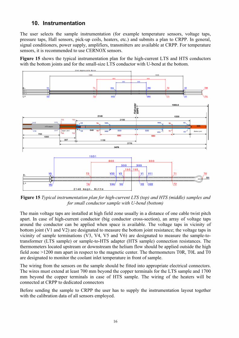
Figure 15 shows the typical instrumentation plan for the high-current LTS and HTS conductors with the bottom joints and for the small-size LTS conductor with U-bend at the bottom.
Figure 15 Typical instrumentation plan for high-current LTS (top) and HTS (middle) samples and for small conductor sample with U-bend (bottom)
The main voltage taps are installed at high field zone usually in a distance of one cable twist pitch apart. In case of high-current conductor (big conductor cross-section), an array of voltage taps around the conductor can be applied when space is available. The voltage taps in vicinity of bottom joint (V1 and V2) are designated to measure the bottom joint resistance; the voltage taps in vicinity of sample terminations (V3, V4, V5 and V6) are designated to measure the sample-to-transformer (LTS sample) or sample-to-HTS adapter (HTS sample) connection resistances. The thermometers located upstream or downstream the helium flow should be applied outside the high field zone >1200 mm apart in respect to the magnetic center. The thermometers T0R, T0L and T0 are designated to monitor the coolant inlet temperature in front of sample.
The wiring from the sensors on the sample should be fitted into appropriate electrical connectors. The wires must extend at least 700 mm beyond the copper terminals for the LTS sample and 1700 mm beyond the copper terminals in case of HTS sample. The wiring of the heaters will be connected at CRPP to dedicated connectors
Before sending the sample to CRPP the user has to supply the instrumentation layout together with the calibration data of all sensors employed.
17
10.1 Sensors with Four Wires
Seven Sub-D-25 connectors are used for sensors like temperature sensors, Hall probes, etc. This type of connector is commonly used for computer parallel ports. The connector version on the user part is „male“.
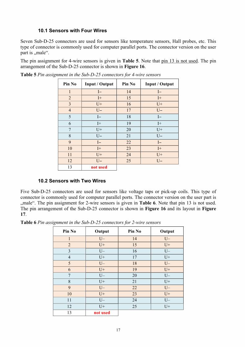
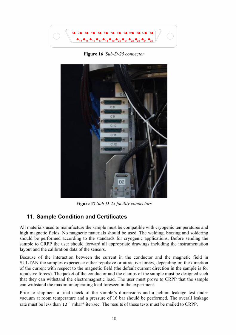
The pin assignment for 4-wire sensors is given in Table 5. Note that pin 13 is not used. The pin arrangement of the Sub-D-25 connector is shown in Figure 16. Table 5 Pin assignment in the Sub-D-25 connectors for 4-wire sensors
Pin No Input / Output Pin No Input / Output
1 I− 14 I− 2 I+ 15 I+ 3 U+ 16 U+ 4 U− 17 U− 5 I− 18 I− 6 I+ 19 I+ 7 U+ 20 U+ 8 U− 21 U− 9 I− 22 I−
10 I+ 23 I+ 11 U+ 24 U+ 12 U− 25 U− 13 not used
10.2 Sensors with Two Wires
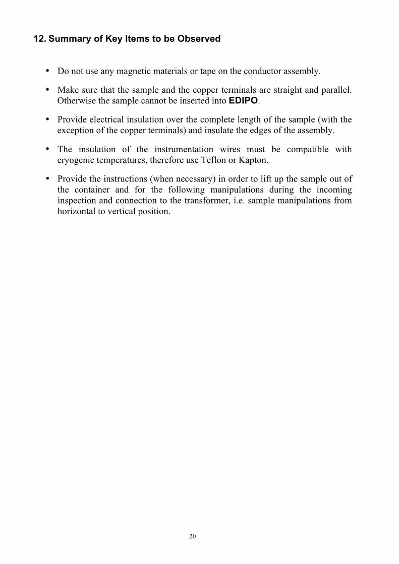
Five Sub-D-25 connectors are used for sensors like voltage taps or pick-up coils. This type of connector is commonly used for computer parallel ports. The connector version on the user part is „male“. The pin assignment for 2-wire sensors is given in Table 6. Note that pin 13 is not used. The pin arrangement of the Sub-D-25 connector is shown in Figure 16 and its layout in Figure 17. Table 6 Pin assignment in the Sub-D-25 connectors for 2-wire sensors
Pin No Output Pin No Output
1 U– 14 U– 2 U+ 15 U+ 3 U– 16 U– 4 U+ 17 U+ 5 U– 18 U– 6 U+ 19 U+ 7 U– 20 U– 8 U+ 21 U+ 9 U– 22 U–
10 U+ 23 U+ 11 U– 24 U– 12 U+ 25 U+ 13 not used
18
Figure 16 Sub-D-25 connector
Figure 17 Sub-D-25 facility connectors
11. Sample Condition and Certificates
All materials used to manufacture the sample must be compatible with cryogenic temperatures and high magnetic fields. No magnetic materials should be used. The welding, brazing and soldering should be performed according to the standards for cryogenic applications. Before sending the sample to CRPP the user should forward all appropriate drawings including the instrumentation layout and the calibration data of the sensors.
Because of the interaction between the current in the conductor and the magnetic field in SULTAN the samples experience either repulsive or attractive forces, depending on the direction of the current with respect to the magnetic field (the default current direction in the sample is for repulsive forces). The jacket of the conductor and the clamps of the sample must be designed such that they can withstand the electromagnetic load. The user must prove to CRPP that the sample can withstand the maximum operating load foreseen in the experiment.
Prior to shipment a final check of the sample’s dimensions and a helium leakage test under vacuum at room temperature and a pressure of 16 bar should be performed. The overall leakage rate must be less than mbar*liter/sec. The results of these tests must be mailed to CRPP.

19
The sample must be supplied as an assembled unit, ready to be inserted into the EDIPO facility. The helium supply pipes must be clean, i.e. free of solid or liquid contamination, and must be protected by removable plugs or caps. Upon arrival of the sample in Villigen the CRPP staff performs a helium leakage test and a dimensional check.
The CRPP staff should be contacted in case of any deviation from the specifications listed above or if further information is required.
20
12. Summary of Key Items to be Observed
• Do not use any magnetic materials or tape on the conductor assembly.
• Make sure that the sample and the copper terminals are straight and parallel. Otherwise the sample cannot be inserted into EDIPO.
• Provide electrical insulation over the complete length of the sample (with the exception of the copper terminals) and insulate the edges of the assembly.
• The insulation of the instrumentation wires must be compatible with cryogenic temperatures, therefore use Teflon or Kapton.
• Provide the instructions (when necessary) in order to lift up the sample out of the container and for the following manipulations during the incoming inspection and connection to the transformer, i.e. sample manipulations from horizontal to vertical position.
Related Documents