1 | Page F1 in Schools ™ Car Design Beginner Tutorial Abstract: After completing this tutorial, you will gain a basic understanding of editing 3D models using Autodesk Fusion 360 to quickly produce an F1 car using a different a range of tools. You will also output an engineering drawing from the model and add dimensions.

Welcome message from author
This document is posted to help you gain knowledge. Please leave a comment to let me know what you think about it! Share it to your friends and learn new things together.
Transcript

1 | P a g e
F1 in Schools
™ Car Design
Beginner Tutorial
Abstract: After completing this tutorial, you will gain a basic understanding of editing 3D models using Autodesk Fusion 360 to quickly produce an F1 car using a different a range of tools. You will also output an engineering drawing from the model and add dimensions.
2 | P a g e
Table of Contents
Introduction ............................................................................................................................... 3
Tutorial Work Flow: ................................................................................................................ 3
Getting Started .......................................................................................................................... 4
Downloading Fusion 360 ........................................................................................................ 4
Datasets ................................................................................................................................. 4
Video Tutorials ....................................................................................................................... 6
F1 in Schools Rules and Technical Regulations ..................................................................... 6
Introduction to Fusion 360 ....................................................................................................... 7
Main User Interface ................................................................................................................ 8
Data Panel Interface .............................................................................................................10
View Navigation ....................................................................................................................10
Mouse ...................................................................................................................................11
Workspaces ..........................................................................................................................12
Understanding Sculpt and Model Workspaces ......................................................................12
Design History .......................................................................................................................13
Autodesk 360 ........................................................................................................................14
Hot Keys ...............................................................................................................................14
Activity 1: Model the F1 Model Block .................................................................................... 15
Step 1: Create a Project ........................................................................................................16
Step 2: Create a New Design and Sketch .............................................................................17
Step 3: Create Features in the Block .....................................................................................20
Activity 2: Modify an Existing F1 in Schools Car Design ..................................................... 26
Step 1: Open an Assembly ....................................................................................................26
Step 2: Design for Manufacture Considerations ....................................................................28
Step 3: Editing the Wings ......................................................................................................31
Step 4: Editing the Form and Splitting the Body ....................................................................41
Activity 3: Checking Dimensions, Exporting as STL files .................................................... 47
Step 1: Check the Dimensions of the F1 Car Design .............................................................48
Step 2: Output the Parts in STL Format ................................................................................50
Activity 4: Creating a Drawing of the F1 Car ......................................................................... 51
Step 1: Create a New Drawing, Create Orthographic View and Add Dimensions ..................52
Next Steps ............................................................................................................................... 55
Credits ..................................................................................................................................... 56
3 | P a g e
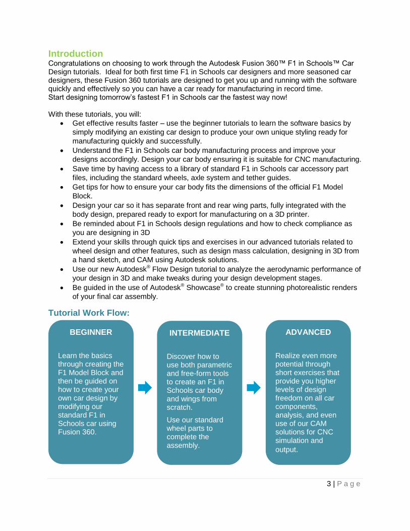
Introduction Congratulations on choosing to work through the Autodesk Fusion 360™ F1 in Schools™ Car Design tutorials. Ideal for both first time F1 in Schools car designers and more seasoned car designers, these Fusion 360 tutorials are designed to get you up and running with the software quickly and effectively so you can have a car ready for manufacturing in record time. Start designing tomorrow’s fastest F1 in Schools car the fastest way now! With these tutorials, you will:
Get effective results faster – use the beginner tutorials to learn the software basics by
simply modifying an existing car design to produce your own unique styling ready for
manufacturing quickly and successfully.
Understand the F1 in Schools car body manufacturing process and improve your
designs accordingly. Design your car body ensuring it is suitable for CNC manufacturing.
Save time by having access to a library of standard F1 in Schools car accessory part
files, including the standard wheels, axle system and tether guides.
Get tips for how to ensure your car body fits the dimensions of the official F1 Model
Block.
Design your car so it has separate front and rear wing parts, fully integrated with the
body design, prepared ready to export for manufacturing on a 3D printer.
Be reminded about F1 in Schools design regulations and how to check compliance as
you are designing in 3D
Extend your skills through quick tips and exercises in our advanced tutorials related to
wheel design and other features, such as design mass calculation, designing in 3D from
a hand sketch, and CAM using Autodesk solutions.
Use our new Autodesk® Flow Design tutorial to analyze the aerodynamic performance of
your design in 3D and make tweaks during your design development stages.
Be guided in the use of Autodesk® Showcase® to create stunning photorealistic renders
of your final car assembly.
Tutorial Work Flow:
BEGINNER
Learn the basics through creating the F1 Model Block and then be guided on how to create your own car design by modifying our standard F1 in Schools car using Fusion 360.
INTERMEDIATE
Discover how to use both parametric and free-form tools to create an F1 in Schools car body and wings from scratch.
Use our standard wheel parts to complete the assembly.
ADVANCED
Realize even more potential through short exercises that provide you higher levels of design freedom on all car components, analysis, and even use of our CAM solutions for CNC simulation and
output.

4 | P a g e
Getting Started
Downloading Fusion 360 Fusion 360 is the first 3D CAD, CAM, and CAE tool of its kind. It connects the entire product development process in a single cloud-based platform that works on both Mac and PC, and has many features accessible from web browser. You can find more information about Fusion 360 and its features here: www.autodesk.com/products/fusion-360/features. To download and use Fusion 360 you will need an Autodesk ID. As a student or educator, you can obtain an Autodesk ID and Fusion 360 at www.autodesk.com/education/free-software/fusion-360.
The design files that you create in Fusion 360 are saved to the cloud-based Autodesk 360 (A360) platform in a Project folder. This means you can access your design files from any web browser or computer with Fusion 360 installed by simply logging in with your Autodesk ID. Projects can be shared with other Fusion 360 users, allowing for design collaboration. As you create your designs, Fusion 360 will save versions and keep a record of your progress. Note: Fusion 360 is currently available for those who are 13 years of age or older.
Datasets All project files that are required to complete the tutorial are provided in a dataset.zip file. Download the dataset file and extract the files to your computer. Do not modify the file structure of the dataset files. Fusion 360 is a cloud-based software. This means you have access to your project files anywhere, as long as your files are saved to a project or a folder in a project. We need a few files to complete our car so let’s upload them to our F1 in Schools project folder. Uploading a data set:
1. Download the dataset to your computer.

5 | P a g e
2. In Fusion 360, click the upload button.
3. Click select files.
4. Locate your files and select them
5. Click upload
Now these files are yours to access wherever you have an internet connection
6 | P a g e
Video Tutorials Download the video tutorials supporting this tutorial. The video tutorials offer the same step-by-step software instruction for learners that prefer guidance through video format.
F1 in Schools Rules and Technical Regulations It is extremely important to that you design your car to comply to the current F1 in Schools rules and regulations. Each country has slightly different specifications that may change from year to year. It is critical that you download and review your country’s F1 in Schools Rules and Regulations documentation and design your car to the outlined specifications. Activities in this tutorial leverage F1 in Schools rules and regulations for 2015-2016 and may not apply to your country. Please confirm the F1 in Schools rules and regulations for your country and competition before getting started. Go to your local F1 website and download the F1 in Schools rules and regulations documentation http://www.f1inschools.com/international-sites/.

7 | P a g e
Introduction to Fusion 360 After logging in to Fusion 360 using your Autodesk ID, you will see your work plane.
1. You should see the work plane below.
8 | P a g e
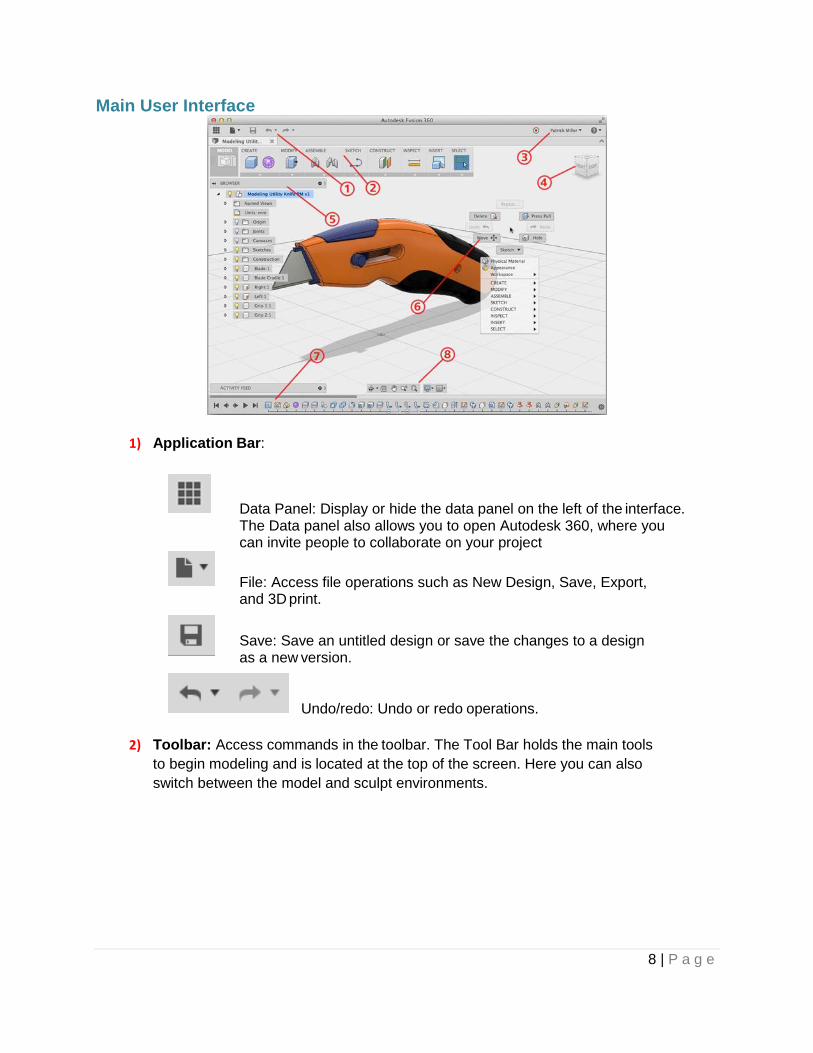
Main User Interface
1) Application Bar:
Data Panel: Display or hide the data panel on the left of the interface. The Data panel also allows you to open Autodesk 360, where you can invite people to collaborate on your project
File: Access file operations such as New Design, Save, Export, and 3D print.
Save: Save an untitled design or save the changes to a design as a new version.
Undo/redo: Undo or redo operations.
2) Toolbar: Access commands in the toolbar. The Tool Bar holds the main tools
to begin modeling and is located at the top of the screen. Here you can also
switch between the model and sculpt environments.
9 | P a g e
3) Profile and Help:
Profile name: Access preferences and your Autodesk profile.
Help: Access help, forums, and tutorials, what’s new, and feedback.
4) ViewCube: Orbit the view and access orthographic and isometric views.
5) Browser: Lists objects in the design.
6) Marking Menu: Another method to access commands. Right-click to display the
marking menu.
7) Timeline: List the operations performed on a design if parametric modeling is active.
8) Navigation Bar and Display Settings: The navigation bar contains commands to navigate the view. The display settings control the display of the design in the canvas. The Navigation Bar allows you to change the model display settings and move around the modeling environment. Use the hand icon to pan or alternatively, use two fingers on a trackpad. You can zoom in and out using the magnifying glass icon or alternatively use the pinch command on a trackpad or scroll wheel on a mouse.

10 | P a g e
Data Panel Interface 1) Project switcher: Select the active project.
2) Project tools
Project Members: Invite
members to the active project.
Project details: Opens the
active project in Autodesk A360
in your default internet browser.
Search: Search the active project
or all projects you have access to.
3) Data tools
Upload: Upload files to Autodesk A360. Many CAD data types are
supported as well as standard files such as documents, spreadsheets,
and presentations.
Data view: Select how data is displayed in the data panel.
Refresh: Refreshes data from Autodesk 360.
4) Thumbnails: Right-click a thumbnail to access commands for that specific design.
View Navigation Use the ViewCube to orbit the design in the canvas. Drag the
ViewCube to perform a free orbit. Click faces and corners of the
ViewCube to access standard orthographic and isometric views.
Use the commands in the Navigation bar to pan, zoom, and orbit the canvas. The
menus on the right end control Display Settings and Layout Grid options.
11 | P a g e
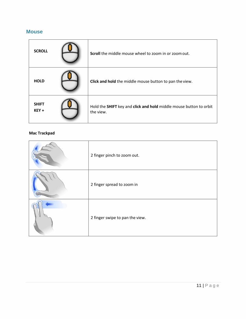
Mouse
SCROLL
Scroll the middle mouse wheel to zoom in or zoom out.
HOLD
Click and hold the middle mouse button to pan the view.
SHIFT
KEY +
Hold the SHIFT key and click and hold middle mouse button to orbit the view.
Mac Trackpad
2 finger pinch to zoom out.
2 finger spread to zoom in
2 finger swipe to pan the view.

12 | P a g e
SHIFT +
Hold SHIFT and 2 finger swipe to orbit the view.
Workspaces Fusion 360 uses workspaces to control the commands that are available and the type of
data that is created. There are multiple workspaces available depending on the work you
plan to perform.
Sculpt: create organic shapes by manipulating faces, edges, and vertices.
Model: create solids with hard edges and flat faces.
Patch: create open surfaces to stitch into solid bodies.
Render: set up the environment and create photo-realistic renderings.
CAM: create and simulate tool-paths, then generate g code for subtractive manufacturing.
Drawing: generate 2D manufacturing drawings.
You also have a drawing workspace for documentation, render workspace for creating photo-
realistic renders, CAM workspace for creating toolpaths.
It’s obvious when to use some workspaces. If you need a 2D manufacturing drawing, you use
the drawing workspace. What about model and sculpt? They are both used to create 3D
designs, so how do you choose one over the other?
Understanding Sculpt and Model Workspaces Fusion 360 allows you to create both free form and parametric models. You will use both methods in this tutorial to create your F1 car. Each one has their uses, advantages and disadvantages. Sculpt The sculpt workspace, free form design, allows you to create curved organic shapes. It involves splitting a model into sections (called T-Splines) and pushing, pulling and twisting them to create beautiful fluid forms.
Model The model workspace, parametric modeling, allows you to create and work with more geometric shapes. It allows you to work accurately with shapes and dimensions and makes editing and updates easy.

13 | P a g e
Design History Fusion 360 can work with or without recording design history. Design history refers to the
operations you perform on the design to create and modify geometry. Operations are
recoded in the timeline at the bottom of the interface.
When using parametric modeling, the design history is captured in the timeline at the bottom of
the interface. Operations are captured in the order they are performed in. History is captured for
commands in the Model and Patch workspaces. You edit the operations in the timeline to make
changes to your design.
When using direct modeling, design history is not captured. The same commands are used
from the toolbar but there is no timeline. You use commands like Press Pull or Move to move
faces and change your design.
So, why use one over the other? Using history allows you to make precise predictable edits to
one or many components and allow the model to rebuild reliably. History is also useful if you
plan to go switch between the model and sculpt workspaces. This allows you to create your
outer shape, then create model operations (shell, split, hole, etc.) then go back and change
your shape. If history is enabled, the model operations will recalculate to fit the new shape.
With direct modeling (history is off), you change geometry by moving faces. There are no
operations to edit and therefore, no relationships between features in the design. Direct
modeling works well for quick concept design or when working the imported data.
You can control the default behavior for new designs using preferences or you can turn
design history on/off in the browser after a model is created.

14 | P a g e
Autodesk 360 Fusion 360 uses Autodesk 360 to manage data and collaborate with teams.
When you access your designs in Fusion, you are actually using A360 under the
hood. You can also access your data in a web browser using A360. A360
provides access and management of the versions of your designs. You can also
upload other supporting design documentation. A360 lets you manage who can
access your design data. All these tools within A360 make it easy to collaborate
with team members.
Hot Keys
Command Windows Mac
Undo Ctrl + Z Command + Z
Redo Ctrl + Y Command + Y
Copy Ctrl + C Command + C
Paste Ctrl + V Command + V
Cut Ctrl + X Command + X
Sculpt Workspace Selection Windows Mac
Grow selection Shift + Up arrow Shift + Up arrow
Shrink selection Shift + Down arrow Shift + Down arrow
Loop selection Alt + P Control + P
Loop grow selection Alt + O Control + O
Ring selection Alt + L Control + L
Ring grow selection Alt + K Control + K
Ring shrink selection Alt + J Control + J
Previous U Alt + Left arrow Control + Command + Left arrow
Next U Alt + Right arrow Control + Command + Right arrow
Previous V Alt + Down arrow Control + Command + Down arrow
Next V Alt + Up arrow Control + Command + Up arrow
Range selection Alt + M Command + M
Invert selection Alt + N Command + N
Toggle box mode Ctrl + 1 Ctrl + 1
Toggle control frame mode Ctrl + 2 Ctrl + 2
Toggle smooth mode Ctrl + 3 Ctrl + 3
Select edge ring Double-click an edge Double-click an edge
Select face ring Select two faces then double- click a third face
Select two faces then double- click a third face
Edit Form Command Windows Mac
Add geometry Alt + Drag Option + Drag
Add geometry and keep creases Alt + Ctrl + Drag Option + Command + Drag
15 | P a g e
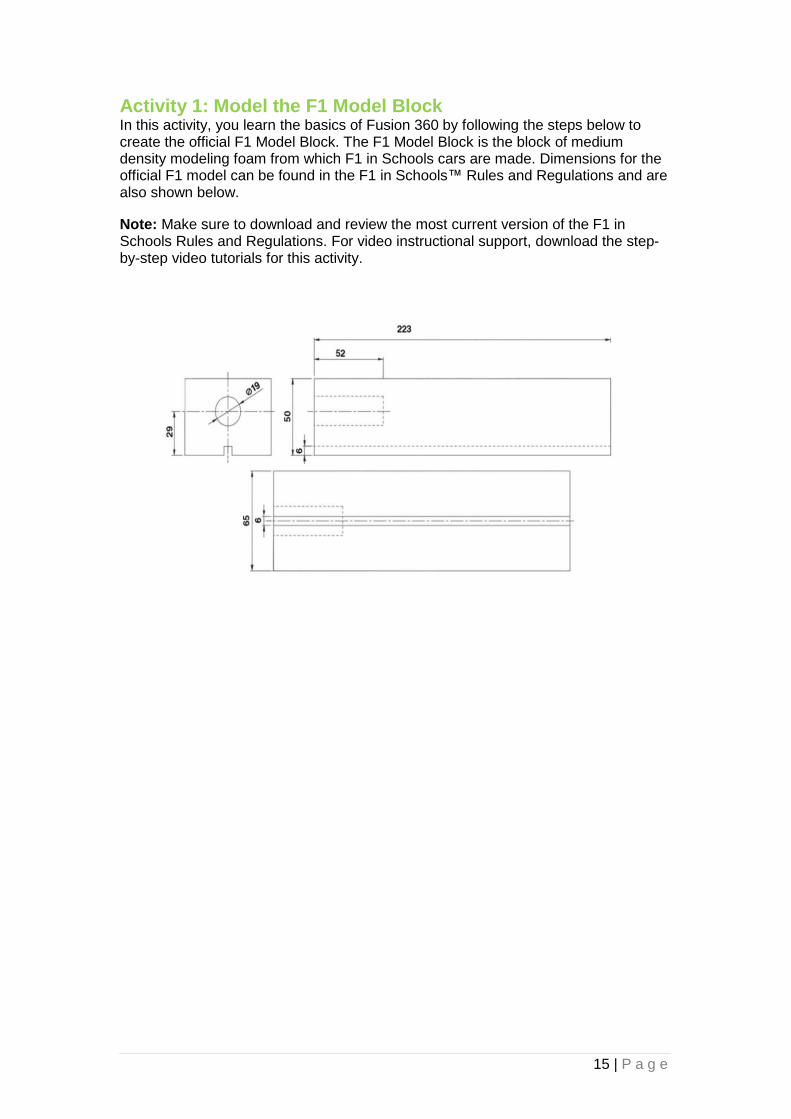
Activity 1: Model the F1 Model Block In this activity, you learn the basics of Fusion 360 by following the steps below to create the official F1 Model Block. The F1 Model Block is the block of medium density modeling foam from which F1 in Schools cars are made. Dimensions for the official F1 model can be found in the F1 in Schools™ Rules and Regulations and are also shown below.
Note: Make sure to download and review the most current version of the F1 in Schools Rules and Regulations. For video instructional support, download the step-by-step video tutorials for this activity.

16 | P a g e
Step 1: Create a Project
1. Expand the Data panel in the Fusion 360 interface and click the New Project button to define the dedicated repository for all designs related to F1 in Schools.
Type in the name of the project, for example ‘F1 in Schools’ and press enter. After a few seconds, the project will appear in the list.
2. Double click the project name to view the contents. By default, it shows all the data available within the project. Now it is empty:
3. If you are working on a team project, invite other team members to the project using the People tab on the right hand side of the window.
4. Return to the main Fusion 360 window.

17 | P a g e
Step 2: Create a New Design and Sketch
1. In Fusion 360, click the File button in the upper-left and select New Design. Before you can save your design, you must start modeling in the workspace.
2. Select Sketch -> Rectangle -> 2-Point Rectangle tool from the dropdown menu to start sketching.
3. Click OK in the notification dialog if it appears. You may also choose not to display this notice in the future.
4. Select the right side plane to base the sketch on.

18 | P a g e
5. Move your cursor to the center of the axis and click when it becomes highlighted to place the corner of the rectangle.
6. Move your cursor up and right to begin to draw a rectangle. In the boxes, type
50(mm) in the box for the vertical line, press Return/Enter and 223(mm) in the horizontal, press Return again to input the dimension. Finally press Return to finish.
Click Stop Sketch.
7. You can now use the Shift key and hold down the middle mouse button (2 fingers on Mac trackpad) to rotate the view. Alternatively, use the view cube to set the orientation you need. The house icon fits the model in the window.
This is called the Origin point

19 | P a g e
8. You will now see that the shape you have created is flat. Now you need to make it solid.
9. From the Create dropdown menu, select Extrude. Select the sketch profile you have just made.
10. In the window, type 32.5 mm for Distance, Select Symmetric for Direction and check New Body is selected for Operation. Click OK.

20 | P a g e
This will create a block that has a plane running through the center of it. This will be useful later on when you need things to be the same on both sides of your car.
11. Save your design by clicking the Save icon on the upper left. Enter a name like ‘F1 in Schools Block’ in the dialog box, and select which A360 project you want to save your design to.
Step 3: Create Features in the Block
1. Now you are going to produce the hole in the end of the block that fits the CO2 cartridge. Select Sketch -> Circle -> Centre Diameter Circle.
21 | P a g e
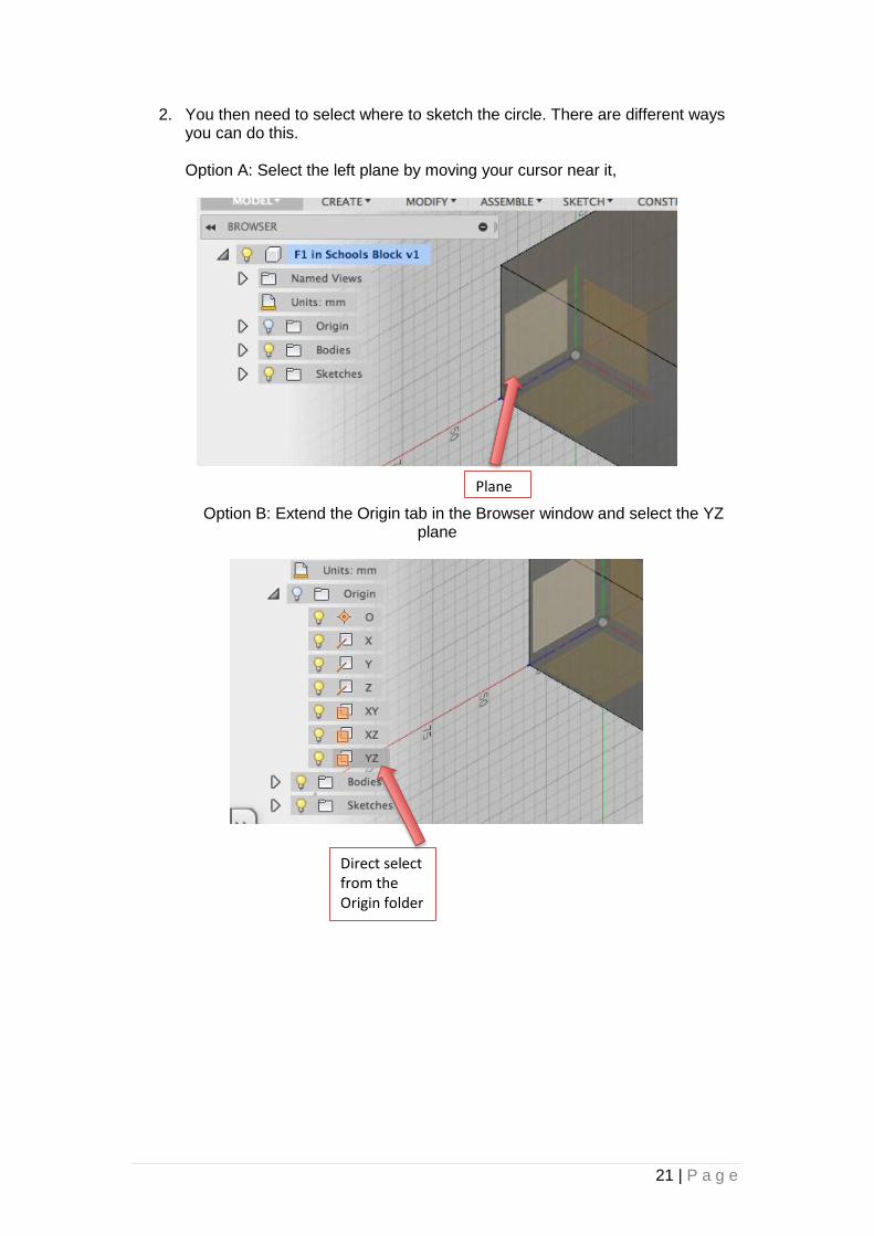
2. You then need to select where to sketch the circle. There are different ways you can do this. Option A: Select the left plane by moving your cursor near it,
Option B: Extend the Origin tab in the Browser window and select the YZ plane
Plane
Direct select from the Origin folder

22 | P a g e
Option C: Use the View Cube to select the left side of the block. This will keep
the back end of the car at the origin, which will be useful later on.
3. Your block will then spin to allow you to work on it easier. On the right side of the window you should see the sketch palette. Make sure Options -> Snap is selected. This makes it easier to position things on the grid.
Rotate the model to select the left face

23 | P a g e
4. Move your cursor up from the origin and you should see a dashed blue line. This indicates it is the center of that face. Go about half way up and click. Dimension the circle to 19mm diameter.
5. You now need to position the circle acutely from the bottom of the block. Select Sketch -> Sketch Dimension from the Tool Bar. Now click the center of your circle and the bottom center of the block (origin point). Change this dimension to 29mm.
6. The circle should update to a new position. Stop the sketch.
7. Select Modify -> Press Pull from the Tool Bar and select the circle.

24 | P a g e
8. In the Extrude window, type a distance of -52mm. By putting Minus (-) it should flick the preview arrow around and make it a Cut inside the block. You can also do this by dragging the blue arrow but it isn’t as accurate. Make sure the Operation says Cut. Click OK.
9. You now need to model the Tether Line Slot. This is the slot that runs underneath the car. Select a Centre Rectangle from the Sketch icon on the Tool Bar. Select the same face as you were just working on. Start the center of the rectangle at the Origin. Make the sizes, 6mm across and 12mm down.
10. Stop the sketch. Select Press Pull from the Tool Bar (or right click to see a shortcut menu). Select the top part of the rectangle to extrude.

25 | P a g e
11. You now need to cut this part all the way through the block. You could drag
the blue arrow inside the block, or select Cut from the Operation option and Through All from Extent. Be sure to select Flip to cut inside the block or you may get an error message.
12. Rotate the model to check everything has worked.
13. You should now notice there is a timeline at the bottom of the screen. This is like a history of everything you have done so far. You can double click to edit these parts and your model will update with the changes.
14. Click the Save icon and name your file.

26 | P a g e
Activity 2: Modify an Existing F1 in Schools Car Design In this activity, you modify an existing F1 in Schools car using the Sculpt command and T-splines. You will then be able to use the techniques learned to very quickly create your own unique body and wing shapes by modifying the standard Autodesk Fusion 360 F1 in Schools Car Model. For video instructional support, download the step-by-step video tutorials for this activity. Following Activity 2, you will be shown how to save parts in *.stl format ready to CNC machine or 3D print and how to generate an orthographic drawing of your 3D F1 in Schools Car assembly.
Step 1: Open an Assembly 1. Select the Data Panel in the top left corner of the screen, open the dataset
folder and select ‘Autodesk Fusion F1 in Schools Car’.
2. Close the data panel when the car is opened.
3. You should see a Browser window on the left side of the screen. If this is not visible, select View -> View Browser. Here you will see all the components that make up this assembly. You can stretch the window to make it easier to read the component names.
Drag to stretch window width
27 | P a g e
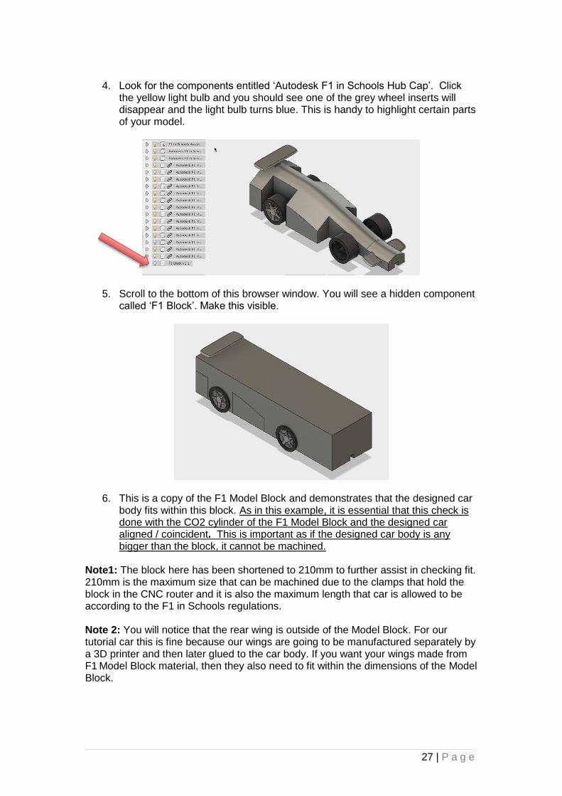
4. Look for the components entitled ‘Autodesk F1 in Schools Hub Cap’. Click
the yellow light bulb and you should see one of the grey wheel inserts will disappear and the light bulb turns blue. This is handy to highlight certain parts of your model.
5. Scroll to the bottom of this browser window. You will see a hidden component called ‘F1 Block’. Make this visible.
6. This is a copy of the F1 Model Block and demonstrates that the designed car body fits within this block. As in this example, it is essential that this check is done with the CO2 cylinder of the F1 Model Block and the designed car aligned / coincident. This is important as if the designed car body is any bigger than the block, it cannot be machined.
Note1: The block here has been shortened to 210mm to further assist in checking fit. 210mm is the maximum size that can be machined due to the clamps that hold the block in the CNC router and it is also the maximum length that car is allowed to be according to the F1 in Schools regulations. Note 2: You will notice that the rear wing is outside of the Model Block. For our tutorial car this is fine because our wings are going to be manufactured separately by a 3D printer and then later glued to the car body. If you want your wings made from F1 Model Block material, then they also need to fit within the dimensions of the Model Block.
28 | P a g e
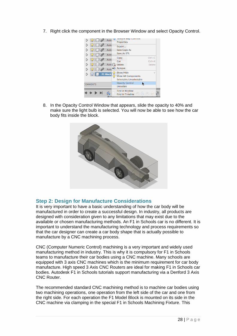
7. Right click the component in the Browser Window and select Opacity Control.
8. In the Opacity Control Window that appears, slide the opacity to 40% and make sure the light bulb is selected. You will now be able to see how the car body fits inside the block.
Step 2: Design for Manufacture Considerations It is very important to have a basic understanding of how the car body will be manufactured in order to create a successful design. In industry, all products are designed with consideration given to any limitations that may exist due to the available or chosen manufacturing methods. An F1 in Schools car is no different. It is important to understand the manufacturing technology and process requirements so that the car designer can create a car body shape that is actually possible to manufacture by a CNC machining process. CNC (Computer Numeric Control) machining is a very important and widely used manufacturing method in industry. This is why it is compulsory for F1 in Schools teams to manufacture their car bodies using a CNC machine. Many schools are equipped with 3 axis CNC machines which is the minimum requirement for car body manufacture. High speed 3 Axis CNC Routers are ideal for making F1 in Schools car bodies. Autodesk F1 in Schools tutorials support manufacturing via a Denford 3 Axis CNC Router. The recommended standard CNC machining method is to machine car bodies using two machining operations, one operation from the left side of the car and one from the right side. For each operation the F1 Model Block is mounted on its side in the CNC machine via clamping in the special F1 in Schools Machining Fixture. This

29 | P a g e
method provides for a wide range of car profile designs to be machined with a minimum amount of machining operations. The picture below illustrates this.
The green arrows above indicate the 3 axis direction system of the CNC machine. These are the three axes of direction that cutting tools move in, often simultaneously, in order to remove the excess Model Block material revealing the profile of your F1 in Schools racer. The standard method of manufacture is to machine the car body using two machining operations, one machining operation on each side of the car. The right side of the car is machined with the Model Block mounted as pictured above, the Model Block is then rotated 180 degrees about the x axis to machine the left side of the car body. The left side machining operation is simply a mirror image of the right side. Due to there being only 3 axes or directions of movement that the cutting tool can move in, some shapes or profiles may not be possible to machine. The diagrams below help explain this further
+Z
+Y
+X
¼ inch / 6.35mm diameter ball nose cutting tool
Fixture
F1 Model Block
The Model Block (green) and car profile (blue) are shown oriented on their side in the
CNC machine. The dark blue circle is the CO2 canister hole
in the Model Block. The cutting tool (shown in grey) can remove all of the
material to produce the design (shown in blue) as it can be reached from left and right
sides of the car. The material shaded in red
cannot be removed as the tool cannot reach this area from the
left and right sides.

30 | P a g e
As pictured on the right, it is possible to mount the Model Block in the CNC Router orientated to allow for machining from the car body top. This can then also be inverted to allow for machining of the car body bottom if required. These would be additional machining processes increasing complexity, time and cost to machine the design. Note that with this design, there are still areas shown in red that the cutter cannot access, these areas are not possible to machine using any orientation. Finally, the size and shape of the cutting tool needs to be considered. The standard machining process for F1 in Schools car bodies uses a ¼ inch (6.35mm) diameter ball nose shaped cutter. Looking at the diagram above, you will notice that a small radius / fillet of material (in red) remains where two edges meet at an internal sharp corner. This is due to the ball nose shape of the cutter tip. The example to the right is a similar body profile to the above example, however here the slot down next to the left and right sides of the CO2 canister housing is not as wide. The slot is narrower than ¼ inch / 6.35mm and therefore the cutter cannot access and remove the material in red. Any slot or groove features like this that are narrower than the diameter of the cutter cannot be machined. Hopefully now you have a better understanding of the CNC machining process used to manufacture F1 in Schools car bodies and the few limitations that this imposes. You should now keep these factors in mind as you unleash your creativity in designing your F1 in Schools racer car bodies.
ABOVE: Material remains in the sharp internal corners (shown in red) due to the ball nose shape of the cutter tip (shown in grey). Model Block material that will be machined away is indicated in
green

31 | P a g e
Step 3: Editing the Wings 1. From the Data Panel, open the Autodesk Fusion F1 in Schools Car.
Note: You will notice this is not an assembly. You will only be editing the body and the wings.
2. Click the + underneath the folder icon at the bottom to open the Timeline.
3. Click on the front wing and you will notice that 3 lines appear over one of the Sculpt icons on the timeline. Right click the icon and select edit, or double click this icon to open up the Sculpt environment. You should notice the Tools change.

32 | P a g e
4. The rest of the components will now be greyed out. The wing is now the active component. You will notice the wing is made of lined sections, called T-splines. These are all editable. Click Modify -> Edit Form.
5. Click on the front left rectangle on the wing. You will notice that the opposite rectangle gets selected also. There is a line of symmetry set up (green line) through the center so any changes you make on one side are reflected on the other.
6. The Triad Indicator allows you to pull and push parts of the sculpted design. Using the Translation arrows, drag to stretch the wing.

33 | P a g e
7. Press Undo to return to normal.
8. This time, turn one of the Rotation handles on the Triad Indicator. You will see the wing twists.
9. Press Undo. Try the same by selecting Edges

34 | P a g e
and selecting Vertices. Notice the different effects. Make sure you click Undo to go back to the original shape.
Note: The Edit Form Window allows you to narrow down the selections.
10. Back on the original shaped wing, click the section as shown below.
35 | P a g e
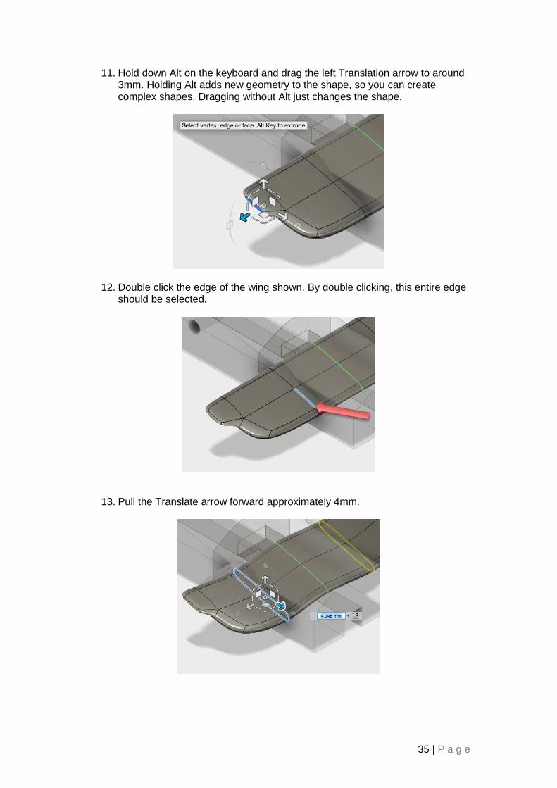
11. Hold down Alt on the keyboard and drag the left Translation arrow to around 3mm. Holding Alt adds new geometry to the shape, so you can create complex shapes. Dragging without Alt just changes the shape.
12. Double click the edge of the wing shown. By double clicking, this entire edge should be selected.
13. Pull the Translate arrow forward approximately 4mm.

36 | P a g e
Note: Rule T8.6 states that the front wheels may only be obstructed to a height of 15mm from the track surface. Because of this you need to alter the positioning of the wing.
14. Select Modify -> Edit Form. Double click one of the faces to select the entire wing.
15. View the car from the side by using the View Cube.
16. Using the top Translate arrow, move the whole wing down approximately 7.5mm.
37 | P a g e
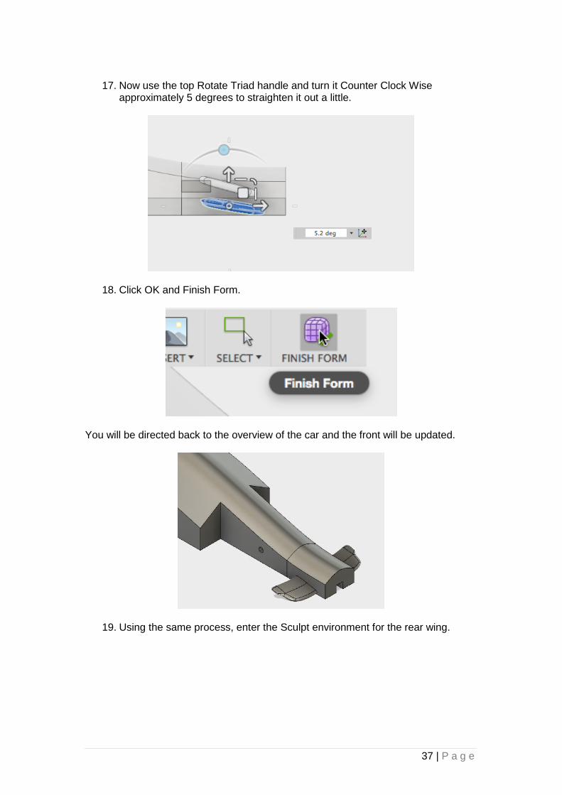
17. Now use the top Rotate Triad handle and turn it Counter Clock Wise
approximately 5 degrees to straighten it out a little.
18. Click OK and Finish Form.
You will be directed back to the overview of the car and the front will be updated.
19. Using the same process, enter the Sculpt environment for the rear wing.

38 | P a g e
20. Select Symmetry -> Mirror Internal.
21. Select the face shown. Then rotate the model to select the face directly underneath it. Click OK. This will create a mirror line through the width of the wing.
22. Select Modify -> Subdivide and select the face of the wing you selected previously, click OK.
39 | P a g e
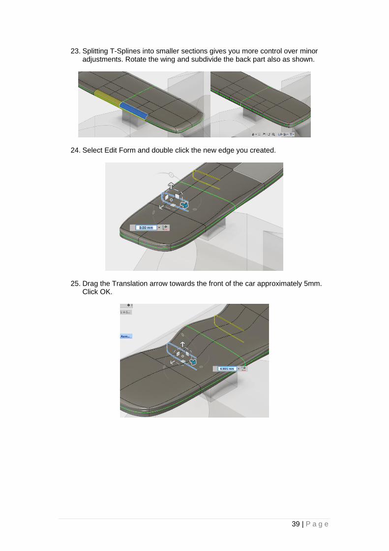
23. Splitting T-Splines into smaller sections gives you more control over minor adjustments. Rotate the wing and subdivide the back part also as shown.
24. Select Edit Form and double click the new edge you created.
25. Drag the Translation arrow towards the front of the car approximately 5mm. Click OK.
40 | P a g e
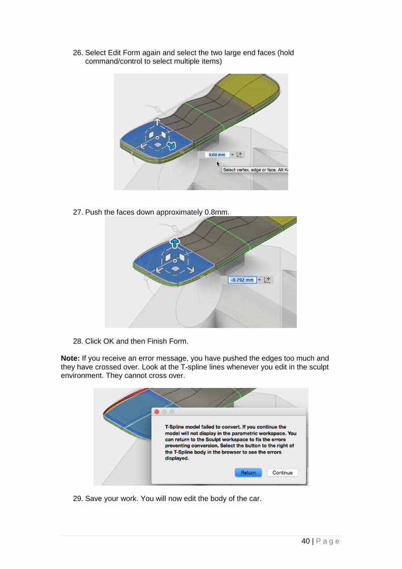
26. Select Edit Form again and select the two large end faces (hold command/control to select multiple items)
27. Push the faces down approximately 0.8mm.
28. Click OK and then Finish Form. Note: If you receive an error message, you have pushed the edges too much and they have crossed over. Look at the T-spline lines whenever you edit in the sculpt environment. They cannot cross over.
29. Save your work. You will now edit the body of the car.

41 | P a g e
Step 4: Editing the Form and Splitting the Body The body of the car is produced in a slightly different way. It is sculpted using T-Splines and then the body is split.
1. Click the body and look for the selected part in the Time Line. Double click the Sculpt icon located before the Split icon which is automatically selected.
Select the car body
Double Click the Sculpt icon to edit
The Split Body icon gets selected

42 | P a g e
2. Again, the body has a line of symmetry through the middle. Double click the left hand edge to select it.
3. Go to Modify -> Edit Form and Click the Translation Triad to stretch it downwards. Type a distance of -10 in the window. Click OK.
4. Modify the same edge again, this time press & hold Alt on the keyboard while pulling the edge approximately 20mm down. Click OK.

43 | P a g e
5. Now modify the 2 Edge T-Splines shown (holding Shift). Click the Triad arrow shown and type -25 to push the front of the car nose inwards. Press OK.
6. Next, subdivide the 3 faces near the back of the car.
Modify, Subdivide
Select these faces

44 | P a g e
7. Select the new edge that has been formed (double click to select its length).
8. Push this edge in 10mm as shown.
9. Rotate the model to check it doesn’t go too close to the canister hole at the back. According to the rules you need to ensure that there is a minimum of 3.5mm (+/- 0.5mm) of Model Block material surrounding the canister hole. Click OK.
45 | P a g e
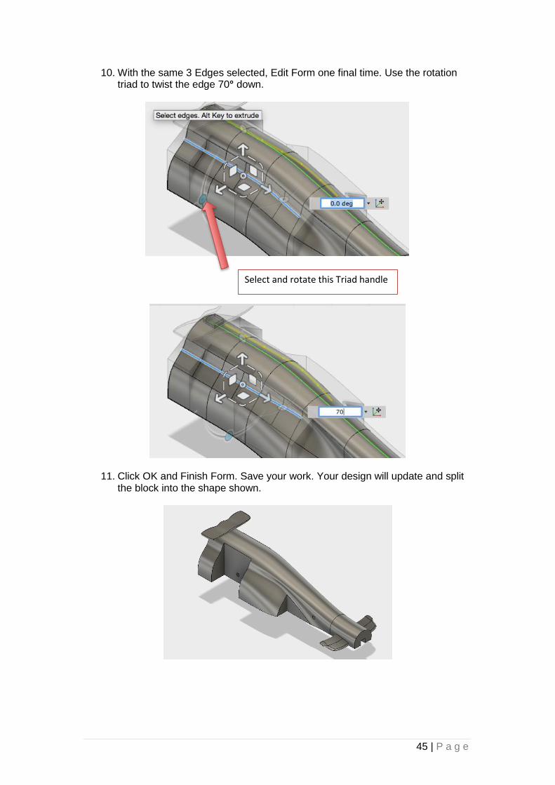
10. With the same 3 Edges selected, Edit Form one final time. Use the rotation triad to twist the edge 70° down.
11. Click OK and Finish Form. Save your work. Your design will update and split the block into the shape shown.
Select and rotate this Triad handle

46 | P a g e
12. Now you will use the tools in the Model Environment to add fillets to your car.
Click Modify -> Fillet.
13. Select (holding Shift) the vertical edges near the wheel spaces. Make sure you select the same on the opposite side.
14. Type in a fillet radius of 3mm. This is to allow for the rounded CNC router, cutting tool that cannot create sharp internal corners when cutting your car.

47 | P a g e
15. Select the front of the car and put a fillet on of 7mm.
16. Apply a 5mm fillet to the edges shown. Be sure to do the other side too.
17. Save your work 18. Now open the original standard /unmodified Autodesk Fusion 360 F1 in
Schools Car and create your own unique design to apply the knowledge and skills you have learned.
Activity 3: Checking Dimensions, Exporting as STL files After making your car design, it is important to check whether your design is suitable for manufacturing. To do this you need to check to see if the body of the car fits within the official F1 in Schools block. You also need to save your parts in a format that the CNC router and 3D printers will recognize (STL format). For video instructional support, download the step-by-step video tutorials for this activity.

48 | P a g e
Step 1: Check the Dimensions of the F1 Car Design 1. Open the Data Panel, right click ‘F1 in Schools Block’ and select ‘Insert into
Current Design’. NOTE: Check to make sure the F1 in Schools Block and your model were created with the same initial layout. It is crucial that the Co2 canister holes line up exactly so that you can ensure your model fits within required dimensions.
2. Close the Data Panel to give you more room. Press OK in the window that appears.
3. Change the opacity of the block and car like you did in Activity 2, Step 1.
49 | P a g e
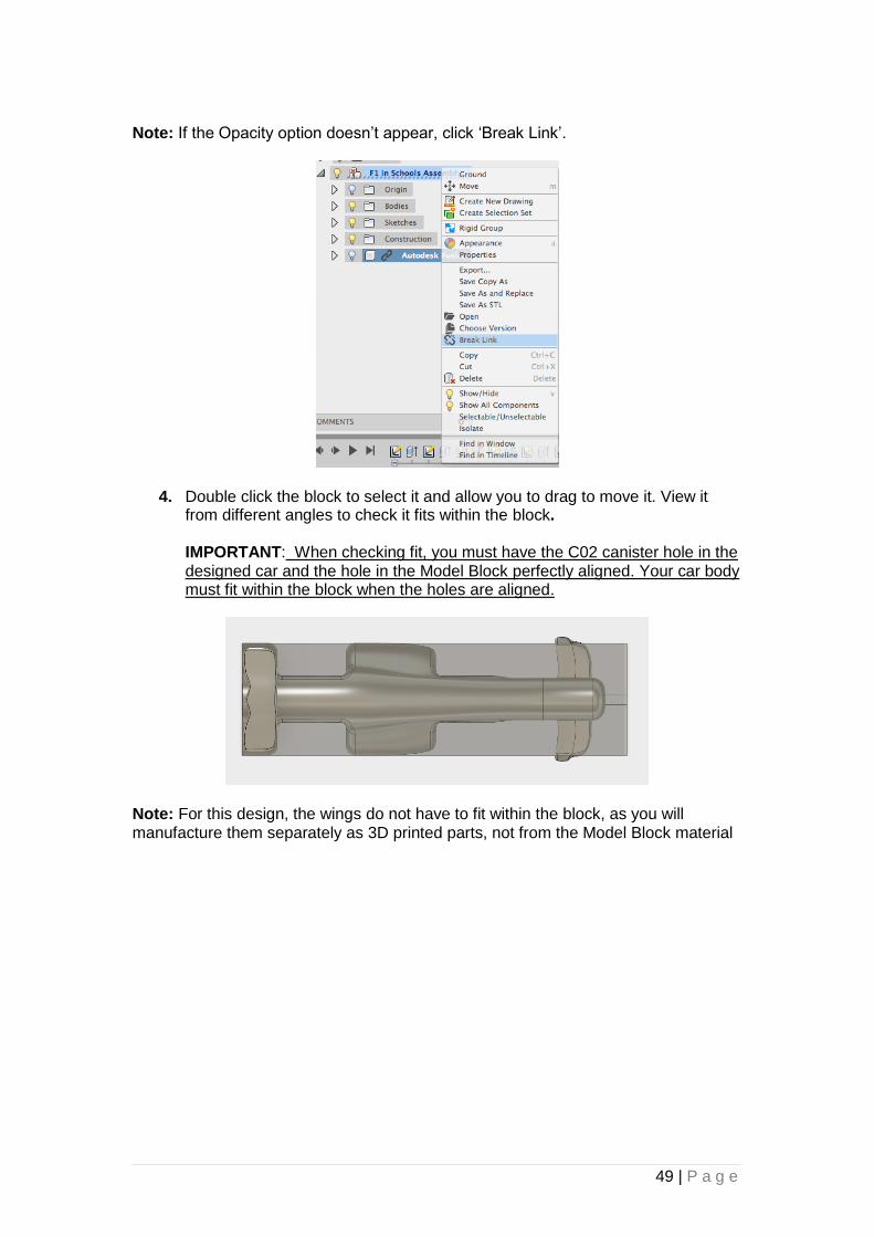
Note: If the Opacity option doesn’t appear, click ‘Break Link’.
4. Double click the block to select it and allow you to drag to move it. View it from different angles to check it fits within the block. IMPORTANT: When checking fit, you must have the C02 canister hole in the designed car and the hole in the Model Block perfectly aligned. Your car body must fit within the block when the holes are aligned.
Note: For this design, the wings do not have to fit within the block, as you will manufacture them separately as 3D printed parts, not from the Model Block material

50 | P a g e
5. You don’t need the block in the window any more. Extend the menu in the Browser window, right click ‘F1 in Schools Block’ and select Delete. Slide the Opacity back to normal.
Step 2: Output the Parts in STL Format Save the parts of the car in .stl format to make them suitable to be CNC machined and/or 3D printed.
1. In the Browser window, open up the Bodies folder and hover over the listed bodies until the model of your car shape is highlighted in the model view. Click the associated Body. The main car body should be selected.
51 | P a g e
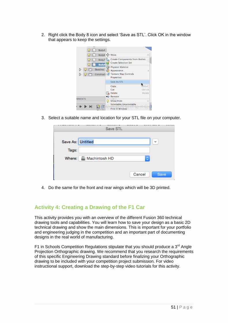
2. Right click the Body 8 icon and select ‘Save as STL’. Click OK in the window
that appears to keep the settings.
3. Select a suitable name and location for your STL file on your computer.
4. Do the same for the front and rear wings which will be 3D printed.
Activity 4: Creating a Drawing of the F1 Car This activity provides you with an overview of the different Fusion 360 technical drawing tools and capabilities. You will learn how to save your design as a basic 2D technical drawing and show the main dimensions. This is important for your portfolio and engineering judging in the competition and an important part of documenting designs in the real world of manufacturing. F1 in Schools Competition Regulations stipulate that you should produce a 3rd Angle Projection Orthographic drawing. We recommend that you research the requirements of this specific Engineering Drawing standard before finalizing your Orthographic drawing to be included with your competition project submission. For video instructional support, download the step-by-step video tutorials for this activity.

52 | P a g e
Step 1: Create a New Drawing, Create Orthographic View and Add Dimensions
1. In the Browser you will see two bodies that are hidden (blue light bulb). Right click and select Remove, or these will show up in the drawing.
2. Select the top feature in the Browser Window, right click and select ‘Create New Drawing’. Give it a suitable name such as ‘Orthographic Drawing’. Make sure the settings are the same as below, click OK.
3. You will be taken into the Drawing Environment. In the View Properties window select 1:2 scale.

53 | P a g e
4. Move your cursor to near the top left of the page. Click to place your car and
click OK. Your car will be drawn on the page from a side view.
5. Select Projected View from the Toolbar.
6. Click your car to use this as the Parent View to base the others from. Move your cursor directly below the car and click. It will create a plan view.
54 | P a g e
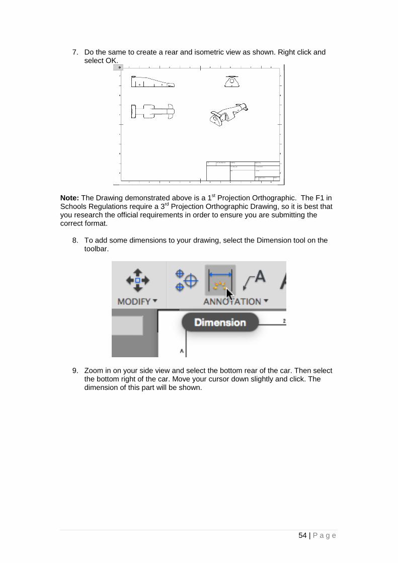
7. Do the same to create a rear and isometric view as shown. Right click and select OK.
Note: The Drawing demonstrated above is a 1st Projection Orthographic. The F1 in Schools Regulations require a 3rd Projection Orthographic Drawing, so it is best that you research the official requirements in order to ensure you are submitting the correct format.
8. To add some dimensions to your drawing, select the Dimension tool on the
toolbar.
9. Zoom in on your side view and select the bottom rear of the car. Then select the bottom right of the car. Move your cursor down slightly and click. The dimension of this part will be shown.

55 | P a g e
10. Do the same for the width of the car.
11. Save your work. 12. Go to the Fusion 360 F1 in Schools Intermediate tutorial to learn about more
advanced Orthographic Drawing functions and features.
Next Steps Now you have successfully edited the existing Autodesk Fusion 360 F1 in Schools car you can move on to the Intermediate tutorial. This will show you how to create your own car design from scratch and how to produce an assembly to include the wheels and show you how to join separate wing components. Before manufacturing your design, you should consider using Autodesk Flow Design software to check your car’s aerodynamic properties. Using this software, you will get results and findings to help you tweak some design features to improve performance. Finally, once your design is final and you have committed to manufacturing, work through the Autodesk Showcase tutorial which will guide you through the process of creating stunning 3D photorealistic renders of your car assembly.

56 | P a g e
Credits Tutorial Author: Ryan Ball, Head of Design Technology, Garden International School Malaysia.
Outline Author/Review Paul Bray, Schools Projects Manager and F1 in Schools Specialist, Yas Marina Circuit
Technical Lead/Author: Jeremy B. Carter, Design Education Evangelist, Autodesk
Technical Lead/Reviewer: Anton Fedoseyev, Premium Support Technical Lead, Autodesk
Partner Manager: Lynn Austin, F1 in Schools Partner Manager, Autodesk
Content Development: Jessica Bendy, Content Development Manager, Autodesk
Related Documents