Procedia Computer Science 18 (2013) 1624 – 1633 1877-0509 © 2013 The Authors. Published by Elsevier B.V. Selection and peer review under responsibility of the organizers of the 2013 International Conference on Computational Science doi:10.1016/j.procs.2013.05.330 International Conference on Computational Science, ICCS 2013 Extended Cyclostatic Dataflow Program Compilation and Execution for an Integrated Manycore Processor Pascal AUBRY a , Pierre-Edouard BEAUCAMPS b , Fr´ ed´ eric BLANC b , Bruno BODIN b , Sergiu CARPOV a , Lo¨ ıc CUDENNEC a , Vincent DAVID a , Philippe DORE a , Paul DUBRULLE a , Benoˆ ıt DUPONT de DINECHIN b , Franc ¸ois GALEA a , Thierry GOUBIER a , Michel HARRAND b , Samuel JONES b , Jean-Denis LESAGE a , St´ ephane LOUISE a , Nicolas MOREY CHAISEMARTIN b , Thanh Hai NGUYEN a , Xavier RAYNAUD b , Renaud SIRDEY a a CEA, LIST, 91191 Gif-sur-Yvette CEDEX, France b Kalray SA, 86 rue de Paris, 91400 Orsay, France Abstract The ever-growing number of cores in embedded chips emphasizes more than ever the complexity inherent to parallel pro- gramming. To solve these programmability issues, there is a renewed interest in the dataflow paradigm. In this context, we present a compilation toolchain for the ΣC language, which allows the hierarchical construction of stream applications and automatic mapping of this application to an embedded manycore target. As a demonstration of this toolchain, we present an implementation of a H.264 encoder and evaluate its performance on Kalray’s embedded manycore MPPA chip. Keywords: sigmac; parallelism; programming language; compilation; cyclostatic dataflow; manycore; embedded. 1. Introduction 1.1. Manycore in embedded environments The generalization of multicore sytems since the beginning of the 21 st century has spread down to embedded devices. Computing parts of today’s smartphones and tomorrow vehicles are increasingly multicore and the new challenge is programming embedded manycore systems. The processing power associated with the emerging manycore systems is a key component toward new classes of applications in the embedded world in accordance with Gustafson’s law [1]. A new area of computing is arising: the embedded High Performance Computing (eHPC). Nonetheless, the key issue of the manycore area is how to express massive parallelism in an application in a manageable way for programmers. ∗ F. Galea tel.: +33-1-6908-1709; fax: +33-1-6908-2082. Available online at www.sciencedirect.com

Welcome message from author
This document is posted to help you gain knowledge. Please leave a comment to let me know what you think about it! Share it to your friends and learn new things together.
Transcript

Procedia Computer Science 18 ( 2013 ) 1624 – 1633
1877-0509 © 2013 The Authors. Published by Elsevier B.V.Selection and peer review under responsibility of the organizers of the 2013 International Conference on Computational Sciencedoi: 10.1016/j.procs.2013.05.330
International Conference on Computational Science, ICCS 2013
Extended Cyclostatic Dataflow Program Compilation andExecution for an Integrated Manycore Processor
Pascal AUBRYa, Pierre-Edouard BEAUCAMPSb, Frederic BLANCb, Bruno BODINb,Sergiu CARPOVa, Loıc CUDENNECa, Vincent DAVIDa, Philippe DOREa,Paul DUBRULLEa, Benoıt DUPONT de DINECHINb, Francois GALEAa,
Thierry GOUBIERa, Michel HARRANDb, Samuel JONESb, Jean-Denis LESAGEa,Stephane LOUISEa, Nicolas MOREY CHAISEMARTINb, Thanh Hai NGUYENa,
Xavier RAYNAUDb, Renaud SIRDEYa
aCEA, LIST, 91191 Gif-sur-Yvette CEDEX, FrancebKalray SA, 86 rue de Paris, 91400 Orsay, France
Abstract
The ever-growing number of cores in embedded chips emphasizes more than ever the complexity inherent to parallel pro-
gramming. To solve these programmability issues, there is a renewed interest in the dataflow paradigm. In this context, we
present a compilation toolchain for the ΣC language, which allows the hierarchical construction of stream applications and
automatic mapping of this application to an embedded manycore target. As a demonstration of this toolchain, we present an
implementation of a H.264 encoder and evaluate its performance on Kalray’s embedded manycore MPPA chip.
Keywords: sigmac; parallelism; programming language; compilation; cyclostatic dataflow; manycore; embedded.
1. Introduction
1.1. Manycore in embedded environments
The generalization of multicore sytems since the beginning of the 21st century has spread down to embedded
devices. Computing parts of today’s smartphones and tomorrow vehicles are increasingly multicore and the new
challenge is programming embedded manycore systems. The processing power associated with the emerging
manycore systems is a key component toward new classes of applications in the embedded world in accordance
with Gustafson’s law [1]. A new area of computing is arising: the embedded High Performance Computing
(eHPC). Nonetheless, the key issue of the manycore area is how to express massive parallelism in an application
in a manageable way for programmers.
∗F. Galea tel.: +33-1-6908-1709; fax: +33-1-6908-2082.
Available online at www.sciencedirect.com
1625 Pascal Aubry et al. / Procedia Computer Science 18 ( 2013 ) 1624 – 1633
1.2. Programmability and data flow programmingToday’s programming concepts coming from the large scale HPC world are mostly focused on OpenMP [2]
and MPI [3]. Neither of them are meet the needs of the embedded field. Moreover, since OpenMP is focused on
threads and shared memory concepts, doubts can be raised on its scalability: data-sharing limits, avoiding both
race conditions, large scale locks and deadlocks is hard [4]. MPI, being message driven, is less of a problem, but
it lacks the soft-real time hooks that are usually required in the embedded world.
The requirements of any language targeting multicore systems are to be able to: easily express massive paral-
lelism, easily detect badly designed applications (at compile time), have a manageable workflow and be determin-
istic enough to permit design tests and easy debugging.
Some of the emerging solutions are based on dataflow paradigms. In the HPC world, this movement is mostly
driven by CUDA [5] and OpenCL [6] whose domain of interest is to develop a means to address the issue of
programming heterogeneous targets with main processors weakly or strongly coupled with accelerators1. Their
usual downside for manycore programming is that they focus too much on the accelerator concept.
Even further in the dataflow concepts, the stream programming languages are raising interest: their advan-
tages rely for a part in their theoretical basis which make them amenable to formal verification of the important
application properties stated above. Two well-known languages in the community are StreamIt [7] and Brook [8].
Another one is ΣC [9] which is a joint development between the CEA LIST and Kalray as a solution to program
Kalray’s new MPPA manycore processor. The topic of this paper is the compilation process of this language, and
especially why it is appropriate for manycore targets and applications.
We shortly describe the MPPA artitecture in Section 2. Then we present in Section 3 the ΣC language and
underlying programming model. Section 4 is an overview of the different aspects involved in the ΣC compilation
toolchain developed as a joint effort by CEA LIST and Kalray for the MPPA architecture. Section 5 presents the
design aspects of a real-world application, and presents performance results. Finally, Section 6 concludes and
presents the current and future works in the ΣC programming environment.
2. The MPPA architecture
The MPPA chip is a (mostly) homogeneous manycore architecture. It contains 256 processing elements (cores)
which are VLIW processors. VLIW are used since they are known for their high energy efficiency with regards to
power consumption (think DSP, e.g. Texas Instruments). These processing elements (PE) which are the number-
crunching parts of the chip are organized in 16 so called “clusters”, each with 16 PEs, and a shared memory. Using
a local shared memory is an interesting part of this architecture, since it enables a high bandwidth and throughput
between the PEs of a single cluster. An additional core is added to each cluster which acts as a scheduler and
manager for the PEs and plays a role in the communication process with other clusters or the external world.
Each cluster is tied to a Network on Chip (NoC) router which is the communication backbone of the chip,
between clusters, but also with so called I/O clusters. These I/O clusters are in charge of managing I/O data
exchanges between either external buses (e.g. PCIe) or SDRAM. As other clusters they have a local processor for
management and interface.
A simplified view of the chip can be seen in Figure 1. Since the first MPPA chip is aimed at simplicity, there
is no implicit communication between clusters and cache coherence is not implemented between the L1 caches
of the PE. This is not an issue with an execution model based on stream processing, since communications are
explicit and data barriers are obvious.
3. The ΣC langage
The basis of stream programming relies on Kahn Process Networks (KPN [10]), more precisely on their
special derivation, Data Process Networks [11]. Process networks eliminate race conditions by construction.
Some restrictive variants, such as Synchronous DataFlow (SDF [12]) or Cyclo-Static DataFlow (CSDF [13]), are
amenable to execution in bounded memory, and the presence of deadlocks can be detected offline [14].
1Nowadays, it usually means GPGPU targets

1626 Pascal Aubry et al. / Procedia Computer Science 18 ( 2013 ) 1624 – 1633
LocalSharedMemory
PE15
NoC node
PE14
PE13
PE12
PE11
PE10
PE9
PE8
DMA InDMA OutManager
Core
PE0
PE1
PE2
PE3
PE4
PE5
PE6
PE7
$I
$D (vliw)
Network on Chip (NoC) and routers
Cluster 0 Cluster 1 Cluster 2
Cluster 4 Cluster 5 Cluster 6 Cluster 7
Cluster 8 Cluster 9 Cluster 10 Cluster 11
Cluster 12 Cluster 13 Cluster 14 Cluster 15
I/O Cluster N
I/O
Clu
ste
r W
I/O Cluster S
I/O
Clu
ste
r E
Cluster 3
Cluster 3 PE0
Multi-bus
Fig. 1. A simplified view of the MPPA chip architecture. Cluster 3 is zoomed to see the details of a cluster with its 16 processing elements(PE). Four I/O clusters ensure the communication with the outside. Clusters communicate between each other thank to a NoC.
ΣC can be related to StreamIt [7], Brook [8], XC [15], or OpenCL [6], i.e. programming languages, either new
or extensions to existing languages, able to describe parallel programs in a stream oriented model of computation.
ΣC defines a superset of CSDF which remains decidable though allowing data dependent control to a certain
extent. CSDF is sufficient to express complex multimedia implementations [16].
As a compiler, ΣC on MPPA can be compared to the StreamIt/RAW compiler [17], that is the compilation
of a high level, streaming oriented, source code with explicit parallelism on a manycore with limited support
for high-level operating system abstractions. However, the execution model supported by the target is different:
dynamic tasks scheduling is allowed on MPPA; the communication topology is arbitrary and uses both a NoC and
shared memory; the average task granularity in ΣC is far larger than the typical StreamIt filter, and the underlying
model (CSDF) is more expressive than StreamIt on RAW because the topology can be arbitrarily defined and is
not limited to (mostly) series-parallel graphs.
Compared to programming IPCs on MPPA, the ΣC compiler relieves the programmer of building per-cluster
executables, computing application-wide identifiers and spreading them in each per-cluster executable, optimizing
the partitioning of its function code and data and communications over the chip (and ensuring each fits in the
memory of each cluster), ensuring the safety, reproducibility and deadlock freeness of the application, while, for
the algorithmic part, keeping the same code.
The goal of the ΣC programming model and language is to ensure programmability and efficiency on many-
cores. It is designed as an extension to C, to enable the reuse of embedded legacy code. This has the advantage
to provide familiarity to embedded developers and allow the use of an underlying C compilation toolchain. It is
designed as a single language, without pragmas, compiler directives or netlist format, to allow for a single view
of the system. It integrates a component model with encapsulation and composition.
3.1. Programming Model
The ΣC programming model builds networks of connected agents. An agent is an autonomous entity, with its
own address space and thread of control. It has an interface describing a set of ports, their direction and the type of
data accepted; and a behavior specification describing the behavior of the agent as a cyclic sequence of transitions
with consumption and production of specified amounts of data on the ports listed in the transition.
A subgraph is a composition of interconnected agents and it too has an interface and a behavior specification.
The contents of the subgraph are entirely hidden and all connections and communications are done with its
interface. Recursive composition is possible and encouraged; an application is in fact a single subgraph named
root. The directional connection of two ports creates a communication link, through which data is exchanged in a
FIFO order with non-blocking write and blocking read operations (the link buffer is considered large enough).
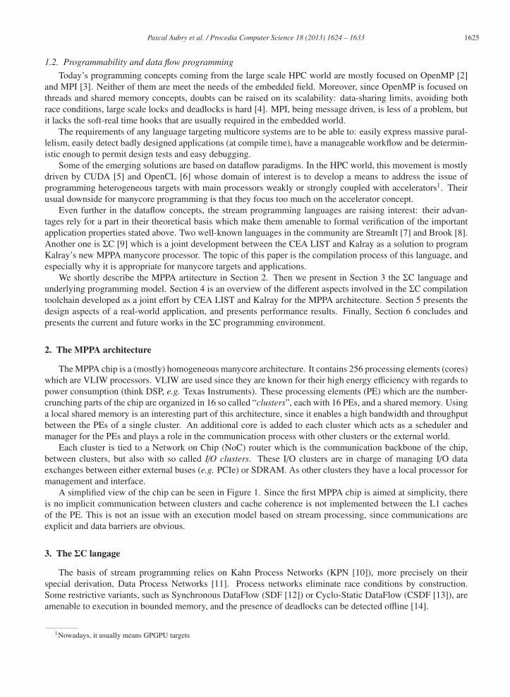
1627 Pascal Aubry et al. / Procedia Computer Science 18 ( 2013 ) 1624 – 1633
1 subgraph r o o t ( i n t width , i n t h e i g h t ) {2 i n t e r f a c e { spec { } ; }3 map {4 agent o u t p u t = new S t r e a m W r i t e r < i n t >(ADDROUT, wid th ∗ h e i g h t ) ;5 agent sy1 = new S p l i t < i n t >( w id th , 1 ) ;6 agent sy2 = new S p l i t < i n t >( w id th , 1 ) ;7 agent j f = new Jo in < i n t >( w id th , 1 ) ;8 connect ( j f . o u t p u t , o u t p u t . i n p u t ) ;9 f o r ( i =0; i < wid th ; i ++) {
10 agent c f = new C o l u m n F i l t e r ( h e i g h t ) ;11 connect ( sy1 . o u t p u t [ i ] , c f . i n 1 ) ;12 connect ( sy2 . o u t p u t [ i ] , c f . i n 2 ) ;13 connect ( c f . out1 , j f . i n p u t [ i ] ) ;14 }15 }16 }
sy1
sy2
cf
jf
cf
cf
cf
Fig. 2. Topology building code, and the associated portion of a ΣC graph, showing multiple column filters (cf) connected to two splits (sy1
and sy2) and one join (jf)
An application is a static dataflow graph, which means there is no agent creation or destruction, and no change
in the topology during the execution of the application. Entity instantiation, initialization and topology building
are performed offline during the compilation process.
System agents ensure distribution of data and control, as well as interactions with external devices. Data
distribution agents are Split, Join (distribute or merge data in round robin fashion over respectively their output
ports / their input ports), Dup (duplicate input data over all output ports) and Sink (consume all data).
3.2. Syntax and examples
Entities are written as a C scoping block with an identifier and parameters, containing C unit level terms
(functions and declarations), and ΣC-tagged sections: interface, init, map and exchange functions.
The communication ports description and the behavior specification are expressed in the interface section.
Port declaration includes orientation and type information, and may be assigned a default value (if oriented for
production) or a sliding window (if oriented for intake).
The construction of the dataflow graph is expressed in the map section using extended C syntax, with the
possibility to use loops and conditional structures. This construction relies on instantiation of ΣC agents and
subgraphs, possibly specialized by parameters passed to an instantiation operator, and on the oriented connection
of their communication ports (as in Figure 2). All assignments to an agent state in its map section during the
construction of the application is preserved and integrated in the final executable.
Exchange functions implement the communicating behavior of the agent. An exchange function is a C function
with an additional exchange keyword, followed by a list of parameter declarations enclosed by parenthesis. Each
parameter declaration creates an exchange variable mapped to a communication port, usable exactly in the same
way as any other function parameter. A call to an exchange function is exactly like a standard C function call, the
exchange parameters being hidden to the caller.
An agent behavior is implemented as in C, as an entry function named start(), which is able to call other
functions as it sees fit, functions which may be exchange functions or not. Figure 3 shows an example of an agent
declaration in ΣC.
4. Description of the toolchain
4.1. Frontend
The frontend of the ΣC toolchain performs syntactic and semantic analysis of the program. It generates per
compilation unit a C source file with separate declarations for the offline topology building and for the online
execution of agent behavior. The instantiation declarations are detailed in subsection 4.2. The declarations for the
online execution of the stream application are a transformation of the ΣC code mainly to turn exchange sections
into calls to a generic communication service. The communication service provides a pointer to a production (resp.

1628 Pascal Aubry et al. / Procedia Computer Science 18 ( 2013 ) 1624 – 1633
1 agent C o l u m n F i l t e r ( i n t h e i g h t ) {2 i n t e r f a c e {3 in< i n t > in1 , i n 2 ;4 out< i n t > ou t1 ;5 spec { i n 1 [ h e i g h t ] ; i n 2 [ h e i g h t ] ; ou t1 [ h e i g h t ] } ; }6 void s t a r t ( ) exchange ( i n 1 a [ h e i g h t ] , i n 2 b [ h e i g h t ] , ou t1 c [ h e i g h t ] ) {7 s t a t i c c o n s t i n t8 g1 [ 1 1 ] = { −1 , −6 , −17 , −17 , 18 , 46 , 18 , −17 , −17 , −6 , −1} ,9 g2 [ 1 1 ] = {0 , 1 , 5 , 17 , 36 , 46 , 36 , 17 , 5 , 1 , 0 } ;
10 i n t i , j ;11 f o r ( i =0; i < h e i g h t ; i ++) {12 c [ i ] = 0 ;13 i f ( i < h e i g h t − 11)14 f o r ( j =0; j < 1 1 ; j ++) {15 c [ i ] += g2 [ j ] ∗ a [ i + j ] ;16 c [ i ] += g1 [ j ] ∗ b [ i + j ] ; }17 }18 }19 }
ColumnFilter
in1
in2
out1
Fig. 3. The ColumnFilter agent used in Figure 2 with two inputs and one output, and the associated portion of ΣC graph
CSDFapplication
Instantiation Parallelismreduction
Dimensioning
E ectiveBu er sizes
Throughputconstraints
Partitionning,placing and
routing
Mapping
NoCdescription
Well-sizedCSDF
Platformdescription
Scheduling
Livenessand minimalbu er sizes
Link edition
SigmaCSource code
Clusterobjects
Fig. 4. The diffi erent stages of the toolchain. Starting with an application written inffff ΣC, we obtain an executable for the MPPA architecture.
intake) area, which is used in code transformation to replace the exchange variable. This leaves the management of
memory for data exchange to the underlying execution support, and gives the possibility to implement a functional
simulator using standard IPC on a POSIX workstation.
4.2. Instantiation and Parallelism Reduction
The ΣC language belongs to the dataflow paradigm in which instances of agents solely communicate through
channels. One intuitive representation of the application relies on a graph, where the vertices are instances of
agents and the edges are channels. This representation can be used for both compiler internal processings and
developer debug interface. This second compiling step of the toolchain aims at building such a representation.
Once built, further analyses are applied to check that the graph is well-formed and that the resulting application
fits to the targeted host. The internal representation of the application (made of C structures) is designed to ease
the implementation and execution of complex graph algorithms.
Instantiating an application is made possible by compiling and running the instantiating program (skeleton)
generated by the frontend parsing step. In this skeleton program, all the ΣC keywords are rewritten using regular
ANSI C code. This code is linked against a library dedicated to the instantiation of agents and communication
channels. The ΣC new agent instructions are replaced by a call to the library’s instance creation function. This
function evaluates the new agent parameters and allocates a new instance in the internal graph. These parameters
can be used to define the initial state of constants and variables, or even set the number of communication ports.
This potentially makes all the instances of the same agent very different, except for the user code. Working on theffff
same basis, a set of functions is provided to instantiate communication ports and channels, and to incrementally
build the complete application graph.
One of the leitmotiv coming with the ΣC language is that the developers should not care about the degree
of parallelism, and that they should only focus on the algorithm side. This is quite a different and uncommonffff
approach regarding regular parallel programming languages. The compiler is therefore in charge of adapting the

1629 Pascal Aubry et al. / Procedia Computer Science 18 ( 2013 ) 1624 – 1633
degree of parallelism of the application to fit the targeted embedded platform, while preserving the semantics and
properties. This step is later refered as parallelism reduction.
The parallelism reduction in the ΣC compilation chain is done in two different ways. Each method has its
benefits and drawbacks. The first method [18] is based on graph pattern substitution. Initially, the instantiations of
a predefined set of patterns are matched in the application (i.e. sub-graphs with a specific structure). Afterwards
each instantiation is replaced by an equivalent pattern of smaller size. The size of the replacement pattern is derived
from a global reduction factor. The goal is to bound the number of actors per processing core to a predefined limit.
A drawback of this method is that the set of patterns must be predefined.
The second method is a generic parallelism reduction. It is based on equivalent agent merge. Two agents are
equivalent if they perform the same computation but on different data streams. All the sets of equivalent agents
are partitioned into subsets. The agents belonging to the same subset are merged together into a single agent. The
sizes of the subsets are chosen such that ΣC application throughput constraints remain satisfied after the merge
operations. The drawback of this method compared to the pattern substitution one is that it does not provide a
fine-grain control over the parallelism reduction, i.e. it can modify the application not in the smartest way.
4.3. Scheduling, Dimensioning, Placing & Routing, Runtime Generation
Once the agents have been instanciated into tasks, the resulting data flow application may pass the scheduling
process. As we are compiling a parallel application for a dynamic parallel scheduling micro-kernel, scheduling
does not consist in fully ordering the execution of the task occurrences and transitions. Instead, it results in a
cyclic partial order of task occurrences, which can be represented with a dependency graph of task occurrences.
The whole scheduling process consists in the following steps. First, one must determine a canonical period,
which corresponds to the execution of one cycle of the application. Basically, once all task occurrences in the
canonical schedule are executed, the application must return to its initial state (list of ready tasks, amount of
data present in the FIFOs). This is determined by calculating the repetition vector which is the minimum non-
zero integer vector whose components correspond to the number of execution cycles of each task transition,
in order to return to the initial state [13]. The number of occurrences for each task in the canonical schedule
is the corresponding component value in the repetition vector multiplied by the task’s number of cyclostatic
transitions. Then, the dependencies between occurrences are determined by symbolic execution of a total order of
all occurrences.
During the symbolic execution, minimum buffer sizes are generated in order to determine a minimum dimen-
sioning of the FIFOs. For this, we consider the FIFO sizes are infinite, and we measure the maximum fill size of
each FIFO during the symbolic execution. Symbolic execution produces a total order of execution of all occur-
rences in the canonical schedule, thus it proves the determined FIFO sizes are sufficient to ensure the canonical
period is executable with no deadlock. Those resulting FIFO sizes strongly depend on the heuristic used in the
symbolic execution for choosing the next task to be symbolically executed. Special care is taken in the choice of
this heuristic to minimize the computed FIFO sizes.
The next step is the computation of effective buffer sizes for the application. Applications require to be exe-
cuted with a certain frequency. For example, a video application requires a certain frame rate. The computation of
buffer size consist in finding minimized buffer sizes that allow to reach the throughput required by the specification
of the application. The execution time for each occurrence is determined by simulation and it allows computation
of throughput or a given storage distribution. Throughput computed at this phase is used for the partitioning.
Once satisfying FIFO sizes have been determined, a working period is generated. The working period consists
in the repetition of several canonical periods, ensuring the allocated buffers for the critical FIFOs may be saturated
during the execution, i.e. the produced (and consumed) amount of data in the period corresponds to the allocated
buffer size. The working period is completed with return dependencies, which are consumer/producer execution
dependencies corresponding to the necessity to not overflow the FIFO buffers. Those dependencies are generated
by performing symbolic execution on each pair of producer and consumer tasks.
Tasks are then mapped on the different clusters of the MPPA chip, and routes are determined for communi-
cation channels between tasks in different clusters. The constraints here are driven by the necessity to respect
the NoC bandwidth, thus tasks are mapped in order to maximize the communication within the clusters, through
concurrent accesses to shared memory. Two placing methods have been implemented for this purpose. The first

1630 Pascal Aubry et al. / Procedia Computer Science 18 ( 2013 ) 1624 – 1633
one involves graph partitioning and quadratic assignment solvers [19]. It typically generates task mappings in less
that 10 seconds, and is suitable in the early cycle of development, where the developer needs fast and repeated
interaction with the compilation toolchain.
The second task mapping method we implemented performs the task mapping in a single step, using a parallel
simulated annealing-based solver [20]. In this case, solving time is longer as it typically takes about 15 minutes
to solve a mapping of around 2000 tasks on a MPPA-like cluster and NoC topology, but solution values in terms
of overall NoC bandwidth usage is much lower. This makes the method suitable in the late cycle of development,
where one can afford to spend time before making the final application ready for running on an embedded chip.
The amount of time the solver actually takes (and thus the quality of the result) can however still be configured to
allow fast prototyping at an early stage of development.
Routing is performed by solving a constrained multiflow problem using an off-the-shelf mixed-integer linear
problem (MILP) solver. As the mapping tends to simplify routing, routing is generally done in less than 5 seconds.
According to the behavior specification of each agent described in the ΣC language, access schemes to the
FIFO buffers are generated to automate the determination of read and write access position in FIFO buffers ac-
cording to the number of the next occurrence of each task.
One major optimization that can be carried out at this stage of the compilation is the inlining or compilation of
the aforementioned system agents. Since these agents do not modify the data they read, but simply reorganize it,
it is possible in many cases to drop the agent from the generated runtime and simply generate a shared buffer, po-
sitioning the pointers of each of the neighboring agents at the appropriate point in the shared buffer and generating
the appropriate pointer increments. The advantages of this optimization are threefold: the system agent does not
need to be scheduled by the runtime, therefore we minimize overheads, the system agent does not need to copy
data from its inputs to its outputs, reducing the overall work, and the shared buffer is often smaller than the sum
of the buffers that would have otherwise been generated, causing significant reductions in memory footprint.
4.4. Link edition and execution supportFor the runtime synchronization of the tasks, the execution support needs runtime data that can be generated
from the information on task behavior gathered in previous compilation steps. One possibility for the execution
support is to use a vector time, as described in [21].
The final stage in the ΣC compiler is the link edition. It consists in building, per cluster hosting tasks, first a
relocatable object file with all the user code, user data and runtime data; then the final binary with the execution
support. All this compilation stage was realized using the GNU binutils for MPPA, with the following constraints:
• constant data declared out of agent scope or shared agent constants are not duplicated;
• variables declared out of agent scope and instance variables are allocated once per task actually accessing
them;
• all functions actually called by a task are linked with the variables allocated for this task, in an object file
we call the task object and in which all symbols are localized.
To obtain the relocatable cluster object, we link the task objects and the object files with the constants and the
runtime data. From there, Memory Protection Unit tables are enough to create the memory context of the tasks.
Depending on external library usage and the size of agent code, some space is wasted with this solution because
of code duplication. It is possible to go further on the MPPA chip because the processor cores support address
translation, which could allow in some cases to share the code between instances.
To link the final binary, the link process adds the execution support that will start the tasks initially ready and
use the runtime data to oversee the execution. The execution support uses the supervision core on MPPA clusters
to support hardware and I/Os. In addition, the supervision core is in charge of the main part of scheduling (it
computes dependencies, allocates tasks to other cores). The other cores just load/unload task contexts to execute
their current activation when they are ready.
5. Application: a H.264 video encoder
Several applications are currently available for the MPPA chip. Most of them have been partially or fully
written in ΣC. Among them is a H.264 video encoder.

1631 Pascal Aubry et al. / Procedia Computer Science 18 ( 2013 ) 1624 – 1633
5.1. H.264 encoder quick overviewH.264/4 MPEG-4 Part 10 or AVC (Advanced Video Coding) is a standard for video compression, and is currently
one of the most commonly used formats for the recording, compression, and distribution of high definition video.
High quality H.264 video encoding requires high compute power and flexibility to handle the different decod-ffff
ing platforms, the numerous image formats, and the various application evolutions.
On the other hand, video encoding algorithms exhibit large amount of parallelism, data, task and instruction
level parallelism lending themselves to efficient execution on manycore processors. This kind of applications can
then be developed using the ΣC environment in order to describe task parallelism when addressing manycore
architectures, such as the MPPA processor.
5.2. H.264 encoder description using ΣC dataflow environmentBased on the x264 library, a parallel implementation of a professional quality H.264 encoder has been made
using the ΣC dataflow language. This implementation starts by partitioning key encoding functions into sepa-
rate modules. Each module contains input and output ports, used for data transfers and data synchronization
(dependencies for example).
The schematic of the parallel implementation of the encoder is shown below. The H.264 encoding process
consists in separately encoding many macroblocks from different rows. This is the first level of parallelization,ffff
allowing a scalable encoding application, where a various number of macroblocks can be encoded in parallel.
In this graph, each “Encode MB Process” subgraph exploits this data parallelism. Fine grained task parallelism
is also described: motion estimation on each macroblock partition (up to 4x4), spatial prediction of intra-coded
macroblocks, RDO analysis and trellis quantization are performed concurrently in separate agents:
EncodeMB process
Reference frame 1
16x16interpolation8x16interpolation16x8interpolation8x8interpolation4x8interpolation8x4interpolation4x4interpolation
Reference frame 2
16x16interpolation8x16interpolation16x8interpolation8x8interpolation4x8interpolation8x4interpolation4x4interpolation
Reference frame n
16x16interpolation8x16interpolation16x8interpolation8x8interpolation4x8interpolation8x4interpolation4x4interpolation
Motion compensationManager
16x16
8x16
16x8
8x8
4x8
8x4 Interpolation
Manager4x4
MB data Manager
MB intraAnalysis
RD inter costAnalysis
16x16 L016x16 L116x16 Bi16x16Direct
Inter 16x8Inter 8x16
Inter 8x8
RD intra costAnalysis
Intra 16x8Intra 8x16
Intra 8x8
MBAnalysis
MB final Encode
CABAC entropycoding
Input frame stream
Outputbitstream
EncodeMBProcess
ReferenceFram
eprocessin
g
EncodeMBProcess
EncodeMBProcess
Fig. 5. H.264 Parallel Implementation.
The ΣC compiler analyzes the dataflow graph and gives to the user an overview of the scheduling of the
application, using profiling data. It is also able to map the application onto the targeted MPPA architecture, and
implements all communication tasks between each ΣC agents.
5.3. Compromise for optimized dataflow descriptionThe ΣC environment supports cyclo-static dataflow application, with execution based on a steady state. The
application then exchanges defined amount of data, independent of runtime’s state or incoming data: in the H.264
algorithm, the amount of data differs according to image type (intra or inter), but theffff ΣC application always works
with data for both cases.
Describing and managing search window for motion estimation is another challenge when using a dataflow
environment: difficulties to describe delay and shared memory between different processes. Fortunately, theffff ΣC
environment implements different kinds of features (including virtual buffff ffers and delays) allowing an effff fficient
implementation (no unnecessary copy, automatic management of data, etc.)
1632 Pascal Aubry et al. / Procedia Computer Science 18 ( 2013 ) 1624 – 1633
5.4. Benefits of ΣC dataflow when developing video application
The ΣC dataflow description helps the user to easily describe and validate data and task parallelism of an
application, abstracting the details of the targeted architecture. He can focus on algorithm development, and
memory optimization (each ΣC agent must contain only useful data for better results). Furthermore, the final
parallelized application can address different kinds of processor architecture based on distributed memory (such
as the MPPA processor).
The ΣC environment takes care of compiling, placing and routing the application. Every step is automatically
made by the compiler. It also includes many optimization techniques, such as double buffering or data coherency
when sharing buffers (ΣC agent inlining). All these operations made by the compiler allow the user to easily
design scalable applications with dynamic configurations: H.264 encoder can then be configured to encode 2, 4,
10 or 16 macroblocks in parallel just by modifying a defined value.
Finally, porting a H.264 encoder to the MPPA processor using the ΣC environment reduces the design time
compared to traditional Posix threads implementations targeting multicore processors or VHDL description for
an FPGA target: ΣC offers an easy way to design an application, thanks to its efficient debugging ability and
the possibility to re-use existent C code. The fast functional simulations are easy to run and decrease validation
time, partitioning and synchronization is hidden by the system software, and all the optimizations are based on
algorithm and buffer sizing.
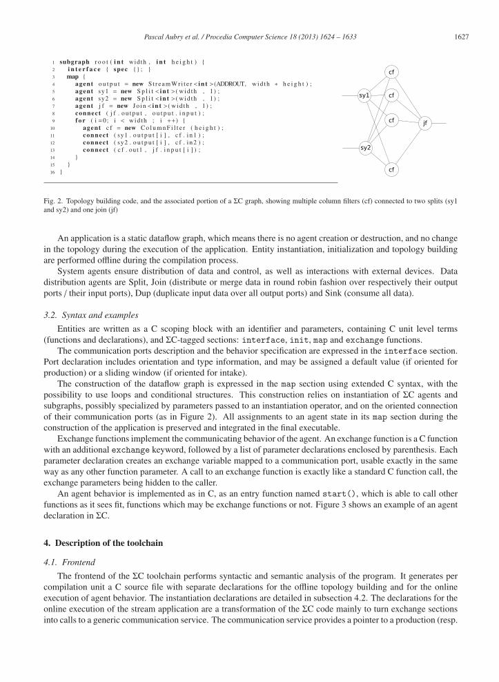
5.5. Results and performance
From the current implementation of the H.264 encoder on ΣC, a performance analysis has been performed to
determine the encoder global quality. Those performance results have been compared to the initial x264 library,
applied on different video sequences frequently used for such analyzes. The conclusions are the following:
- From a quality analysis based on bitstream size and decoded video quality (using SSIM and PSNR criteria),
the parallelized H.264 application using ΣC dataflow language offers better results than the initial x264.
Using MPPA manycore architecture leads to a less restricted implementation (fewer thresholds, less bypass,
etc.). For example, many motion vectors can be tested in parallel, as well as many intra predictors, without
impacting encoder speed. Finally, much more information is available, enabling a better solution, impacting
the resulted encoder quality.
- Implementation of the x264 library on the MPPA processor offers a real-time encoder, for embedded solu-
tions, and low-power needs. It achieves about 110 frames per second in the Intra I-frame case, 40 FPS for
Inter P-frame and 55 FPS for Inter B-frame.
- Using a configuration equivalent to the implementation on MPPA, the x264 encoder has been tested on
an Intel Core i7-3820 (4 hyper-threaded cores). All CPU capabilities have been used, such as MMX2,
SSE2Fast, SSSE3, FastShuffle and SSE4.2. A performance comparison is presented below:
Processor Performance Energy efficiency
Intel Core i7-3820 52 FPS 2.5 W/FPS
Kalray MPPA-256 49 FPS 0.4 W/FPS
It can be concluded that for equivalent H.264 encoding performance, the ΣC implementation on the Kalray
MPPA-256 processor offers better energy efficiency (about 6 times lower energy consumption).
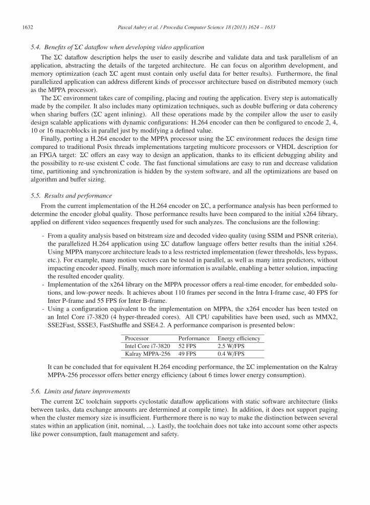
5.6. Limits and future improvements
The current ΣC toolchain supports cyclostatic dataflow applications with static software architecture (links
between tasks, data exchange amounts are determined at compile time). In addition, it does not support paging
when the cluster memory size is insufficient. Furthermore there is no way to make the distinction between several
states within an application (init, nominal, ...). Lastly, the toolchain does not take into account some other aspects
like power consumption, fault management and safety.

1633 Pascal Aubry et al. / Procedia Computer Science 18 ( 2013 ) 1624 – 1633
6. Conclusion and future works
In this paper, we described an end-to-end compilation toolchain and an execution support for the ΣC language,
with an illustration of its performance on an implementation of a H.264 video encoder. Doing so, we assert in
practice that the ΣC language meets the criteria enounced in [9] (good expressivity, efficient integration of existing
C code, properties allowing a compiler to provide guarantees on produced binaries as well as support of modularity
and code reuse, and to produce binaries fit for execution on embedded manycores). The performance results of the
video encoder also demonstrate that, combined to the development ease given by a stream language, architectures
like the MPPA chip offer a good alternative to VHDL description and FPGA-based solutions.
In January 2013, HEVC video compression standard has been released. This new standard offers better and
easier solutions for manycore architecture: increases potential parallelism, reduces number of critical path (like
CABAC), allows more computation for better results, etc. It could be interesting to make a ΣC implementation of
HEVC and evaluate it on the MPPA chip.
Looking at the place and route stage of the toolchain, some ongoing studies in order to include energy related
criteria as well as to allow dynamic reconfiguration at startup. This last point allows an application to run on some
degraded MPPA devices with respect of minimal caracteristics.
Some works have been started to mix, on a MPPA device, both safety-critical modules and high-performance
one. The step forward is to offer a way to design high performance real-time applications.
Some studies intend to allow building dataflow graphs at runtime and provide dynamic channel sizing. This
may be useful for instance in cognitive radio where the device has to adjust its configuration to its environment.
Finally there are ongoing studies to both improve target abstraction and make implementation of some algo-
rithm easier. This refers to extensions to support a DSM (Distributed Shared Memory) and OpenMP.
References
[1] J. L. Gustafson, Reevaluating Amdahl’s law, Communications of the ACM 31 (1988) 532–533.
[2] OpenMP Architectural Review Board, OpenMP 3.0 specification (2008).
[3] M.-P. I. Forum, MPI: A Message-Passing Interface standard.
[4] E. A. Lee, The problem with threads, Computer 39 (5) (2006) 33–42.
[5] NVIDIA Corp., NVIDIA CUDA: Compute Unified Device Architecture, Tech. rep. (2007).
[6] Khronos OpenCl Working Group, The Opencl specification v1.1, Tech. rep. (2011).
[7] S. Amarasinghe, M. I. Gordon, M. Karczmarek, J. Lin, D. Maze, R. M. Rabbah, W. Thies, Language and compiler design for streaming
applications, International Journal of Parallel Programming 33 (2/3) (2005) 261–278.
[8] I. Buck, T. Foley, D. Horn, J. Sugerman, K. Fatahalian, M. Houston, P. Hanrahan, Brook for GPUs: stream computing on graphics
hardware, in: International Conference on Computer Graphics and Interactive Techniques, ACM New York, USA, 2004, pp. 777–786.
[9] T. Goubier, R. Sirdey, S. Louise, V. David, ΣC: A Programming Model and Language for Embedded Manycores, Vol. 7016 of Lecture
Notes in Computer Science, Springer Berlin Heidelberg, 2011, pp. 385–394.
[10] G. Kahn, The semantics of a simple language for parallel programming, in: J. L. Rosenfeld (Ed.), Information processing, North Holland,
Amsterdam, Stockholm, Sweden, 1974, pp. 471–475.
[11] E. A. Lee, T. Parks, Dataflow process networks, in: Proceedings of the IEEE, 1995, pp. 773–799.
[12] E. Lee, D. Messerschmitt, Synchronous data flow, Proceedings of the IEEE 75 (9) (1987) 1235 – 1245. doi:10.1109/PROC.1987.13876.
[13] R. L. G. Bilsen, M. Engels, J. A. Peperstraete, Cyclo-static data flow, IEEE Transactions on Signal Processing 44 (2) (1996) 397–408.
[14] J. T. Buck, E. A. Lee, Scheduling dynamic dataflow graphs with bounded memory using the token flow model, Tech. rep. (1993).
[15] D. Watt, Programming XC on XMOS Devices, XMOS Limited, 2009.
[16] K. Denolf, M. Bekooij, J. Cockx, D. Verkest, H. Corporaal, Exploiting the expressiveness of cyclo-static dataflow to model multimedia
implementations, EURASIP Journal on Advances in Signal Processing 2007 (1) (2007) 084078.
[17] M. I. Gordon, W. Thies, M. Karczmarek, J. Lin, A. S. Meli, C. Leger, A. A. Lamb, J. Wong, H. Hoffman, D. Z. Maze, S. Amarasinghe,
A stream compiler for communication-exposed architectures, in: International Conference on Architectural Support for Programming
Languages and Operating Systems, San Jose, CA USA, 2002.
URL http://groups.csail.mit.edu/commit/papers/02/streamit-asplos.pdf
[18] L. Cudennec, R. Sirdey, Parallelism reduction based on pattern substitution in dataflow oriented programming languages, in: Proceedings
of the 12th International Conference on Computational Science, 2012.
[19] R. Sirdey, Contributions a l’optimisation combinatoire pour l’embarque : des autocommutateurs cellulaires aux microprocesseurs mas-
sivement paralleles, HDR Thesis, Universite de Technologie de Compiegne (Nov. 2011).
[20] F. Galea, R. Sirdey, A parallel simulated annealing approach for the mapping of large process networks, in: PCO’12 as part of the 26th
IEEE International Parallel & Distributed Processing Symposium (IPDPS’12), Shanghai, China, 2012, pp. 1781–1786.
[21] P. Dubrulle, S. Louise, R. Sirdey, V. David, A low-overhead dedicated execution support for stream applications on shared-memory
CMP, in: Proceedings of the tenth ACM international conference on Embedded software, EMSOFT ’12, ACM, New York, USA, 2012,
pp. 143–152.
Related Documents