18th International Symposium on the Application of Laser and Imaging Techniques to Fluid Mechanics・LISBON | PORTUGAL ・JULY 4 – 7, 2016 Experimental study of laser ignition probability, kernel propagation and air and fuel droplet properties in a confined swirled jet-spray burner Javier Marrero Santiago 1,* , Antoine Verdier 1 , Gilles Godard 1 , Alexis Vandel 1 , Gilles Cabot 1 , Mourad Boukhalfa 1 and Bruno Renou 1 1: CORIA-UMR6614, Normandie Université, CNRS, INSA et Université de Rouen, 76800 Saint Etienne du Rouvray, France * Correspondent author: [email protected] Keywords: Swirl jet-spray flame, PDA, Spray ignition, Two-phase combustion, Flame kernel propagation, Laser ignition ABSTRACT Spray combustion is largely used in industrial applications such as aeronautical engines. New engine designs must reduce emissions and increase efficiency through lean combustion. This can carry flame stability problems and re- ignition in altitude has to be well addressed. Two-phase flow ignition and combustion have to be well understood in order to enable technological evolution in this direction. This investigation proposes a laser induced ignition study in a real confined swirled jet-spray burner. Phase Doppler anemometry (PDA) is used to characterise airflow velocity and fuel droplet size distribution and velocity in first place. A probabilistic approach to ignition is presented and propitious regions for ignition are identified. High-speed visualisation is used to track the flame kernel movement and development inside the burner in order to analyse the possible paths followed by the kernel towards a stabilised flame or towards extinction. Results show how local properties vary along the chamber. Airflow velocity and turbulent kinetic energy are very intense in the central region of the burner, over the annular co-flow. Fuel droplets of big diameters show high slip velocities, which are greater outside the air jet. These parameters control droplet evaporation and vapour repartition, and have a great impact on ignition probability. The probabilistic ignition study coupled to the kernel high-speed visualisation reveals that a flame kernel is more likely to survive if trapped by the outer recirculation zone (ORZ), showing great correlation with the airflow velocity field. Ignition probabilities grow towards the chamber lateral walls. The different steps of the development of a kernel towards a stabilised flame are compared to the pressure variation in the chamber. This investigation is useful for numerical simulation validations and contributes to scientific knowledge on two-phase ignition. 1. Introduction New aeronautical burner designs must move onto configurations with lower pollutant emissions and higher efficiencies. This demands a better comprehension of the processes involved in two- phase combustion and ignition. Aeronautical engines present very complex geometries. Here, combustion carries coupled multi-physical and chemical constraints. Flame temperature and burning velocity decrease for low fuel-to-air ratios, implying an increase in flame instabilities. This issue can be translated into more frequent flame extinctions and more difficult flame

Welcome message from author
This document is posted to help you gain knowledge. Please leave a comment to let me know what you think about it! Share it to your friends and learn new things together.
Transcript
18th International Symposium on the Application of Laser and Imaging Techniques to Fluid Mechanics・LISBON | PORTUGAL ・JULY 4 – 7, 2016
Experimental study of laser ignition probability, kernel propagation and air and fuel droplet properties in a confined swirled jet-spray burner
Javier Marrero Santiago1,*, Antoine Verdier1, Gilles Godard1, Alexis Vandel1, Gilles Cabot1, Mourad Boukhalfa1 and Bruno Renou1
1: CORIA-UMR6614, Normandie Université, CNRS, INSA et Université de Rouen, 76800 Saint Etienne du Rouvray, France * Correspondent author: [email protected]
Keywords: Swirl jet-spray flame, PDA, Spray ignition, Two-phase combustion, Flame kernel propagation, Laser ignition
ABSTRACT
Spray combustion is largely used in industrial applications such as aeronautical engines. New engine designs must
reduce emissions and increase efficiency through lean combustion. This can carry flame stability problems and re-
ignition in altitude has to be well addressed. Two-phase flow ignition and combustion have to be well understood
in order to enable technological evolution in this direction. This investigation proposes a laser induced ignition
study in a real confined swirled jet-spray burner. Phase Doppler anemometry (PDA) is used to characterise airflow
velocity and fuel droplet size distribution and velocity in first place. A probabilistic approach to ignition is
presented and propitious regions for ignition are identified. High-speed visualisation is used to track the flame
kernel movement and development inside the burner in order to analyse the possible paths followed by the kernel
towards a stabilised flame or towards extinction. Results show how local properties vary along the chamber.
Airflow velocity and turbulent kinetic energy are very intense in the central region of the burner, over the annular
co-flow. Fuel droplets of big diameters show high slip velocities, which are greater outside the air jet. These
parameters control droplet evaporation and vapour repartition, and have a great impact on ignition probability. The
probabilistic ignition study coupled to the kernel high-speed visualisation reveals that a flame kernel is more likely
to survive if trapped by the outer recirculation zone (ORZ), showing great correlation with the airflow velocity field.
Ignition probabilities grow towards the chamber lateral walls. The different steps of the development of a kernel
towards a stabilised flame are compared to the pressure variation in the chamber. This investigation is useful for
numerical simulation validations and contributes to scientific knowledge on two-phase ignition.
1. Introduction
New aeronautical burner designs must move onto configurations with lower pollutant emissions
and higher efficiencies. This demands a better comprehension of the processes involved in two-
phase combustion and ignition. Aeronautical engines present very complex geometries. Here,
combustion carries coupled multi-physical and chemical constraints. Flame temperature and
burning velocity decrease for low fuel-to-air ratios, implying an increase in flame instabilities.
This issue can be translated into more frequent flame extinctions and more difficult flame

18th International Symposium on the Application of Laser and Imaging Techniques to Fluid Mechanics・LISBON | PORTUGAL ・JULY 4 – 7, 2016
ignitions. In this context, engine re-ignition in altitude for lean air-spray mixtures has to be well
understood. Many parameters within the flow will determine whether a flame kernel inside the
chamber will evolve into a stable flame or not. Indeed, the initial location of the kernel is very
important because flow conditions vary strongly along the burner. Air velocity field, air
temperature field, wall and fuel temperature, fuel droplet size distribution and velocity field,
and turbulence level have great impact on ignition probability and on flame structure and
stabilisation. Fuel evaporation and vapour spatial repartition also depend on these parameters,
and they vary locally too. For this reason, initial conditions have to be correctly characterised as
a first step towards addressing ignition. Two-phase reacting flows have already been
investigated by Kourtmatzis A et al., Correia H et al., Andrew P et al., Cléon G et al., Nicolia C et
al., Morkous S et al. and Sánchez AL et al. but they still remain a challenge for experiments and
simulations in various aspects. For instance, the presence of droplets complicates the
performance of experimental measurements. Anyway, several classical and new laser techniques
can deal with these conditions and many have been conceived for this purpose. Investigations on
ignition have been performed by Garcia N et al., Linassier G et al. and Hwan Lee S et al. but still,
the scientific knowledge on the mechanisms that control the transition from a spark to a
stabilised flame is currently not enough. Ignition is a fast process strongly influenced by local
flow properties. In order to quantify the propitious and adverse regions for ignition, a
probabilistic approach is necessary as done by Cordier M et al. Most sparks in engines are
currently generated by an electrical potential difference between two electrodes. This presents a
number of problems. Indeed, the electrodes perturb the flow and act as heat sinks, and the
location of the spark in the gap is not easy to control. An alternative approach to ignition is the
generation of a spark by a focalised laser beam. Works on laser ignition have been performed by
Cardin C et al., Letty C et al., Mulla IA et al. and Lawes M et al. Still, it is a technique that has to
be further studied and developed. It presents several advantages such as a very high precision
on the deposited energy quantity and location, plus the absence of electrodes.
In this context, the present investigation focuses on an ignition probability study coupled with
the analysis of flame kernel propagation with a previous description of the aerodynamics of the
air and droplets. A canonical n-heptane confined swirled spray flow will be presented and
studied by applying different measurement techniques. Phase Doppler Anemometry (PDA) has
been used to measure fuel droplet size, velocity and distribution, and air co-flow velocity in non-
reactive conditions. Once the initial aerodynamic conditions are determined, a statistical study
on laser ignition probability will be presented, according to the local statistics of carrier phase
velocity and fuel droplet properties. High-speed flame emission visualisation allows tracking the

18th International Symposium on the Application of Laser and Imaging Techniques to Fluid Mechanics・LISBON | PORTUGAL ・JULY 4 – 7, 2016
movement and development of the kernel inside the chamber in order to study the different
possible pathways that can drive the ignition process to succeed or not. The pressure signal in
the chamber will be simultaneously registered.
2. Experimental set-up and optical diagnostics
Experiments are carried out in a two-phase flow version of the KIAI burner (Cordier M et al.),
confined with quartz windows in order to allow full optical access (Fig. 1). The system is
composed of a simplex pressure atomizer (Danfoss, 1.46 kgh-1, 80° hollow cone) and an external
annular swirling air co-flow with an inner and outer diameter of 10 and 20 mm respectively. The
radial swirler is composed of 18 rectangular (6 mm x 8 mm) channels inclined at 45° with a
corresponding swirl number of 0.76 (Cordier M). Air and liquid fuel (n-heptane) mass flow rates
are controlled by thermal and Coriolis mass flow controllers. The air and fuel inlet conditions are
8.2 gs-1 (T=413 K) and 0.28 gs-1 (T=293 K before entering the chamber) respectively. The airflow
leaves the annular pipe to enter the combustion chamber as a turbulent jet at a bulk velocity of
40.7 ms-1 with a strong swirling motion establishing low pressures and a consequent
recirculation region at the centre of the burner. The airflow velocity has great impact on droplet
distribution, mixing the droplets of different sizes and giving a heterogeneous distribution in all
regions along the chamber. Figure 1 also provides a photograph of the flame emission where one
can see the spray at the nozzle exit and green and blue lasers for PDA.
Fig. 1 Detail of the injection system and flame picture with PDA lasers. The spray cone is seen at the nozzle exit.
Droplet size and velocity are measured by a commercial PDA system (DANTEC) operating in
FIBER mode. An argon laser provides green (514.5 nm) and blue (488 nm) beams. Beam spacing
is 50 mm; transmitting and receiving lenses focal lengths are 350 mm and 310 mm, respectively.
Air
inlet
Fuel
Z
0 10 20 30 40 X (mm)r (mm)

18th International Symposium on the Application of Laser and Imaging Techniques to Fluid Mechanics・LISBON | PORTUGAL ・JULY 4 – 7, 2016
Due to technical reasons, the off-axis angle of the receiving optics is 50° (in front scattering
position), not far from the Brewster angle which, in parallel polarization, enhances the refracted
light detection over the reflected light, reducing the trajectory and slit effects. The laser energy
before the beam separation in this work is 2 W. The used aperture mask allows a detection
diameter range of 139 μm. The measurement volume can be approximated by a cylinder of 120
μm in diameter and 200 μm in length. At each measurement location, data sampling is limited to
40,000 droplets or to 30 s of measuring time, allowing converged statistics of size-classified data.
Due to the spray structure and particle concentration distribution, the measurements are not
possible below z=10 mm. The gain and voltage in the photomultipliers (PMs) are adjusted so as
not to saturate the anode currents in order to correctly detect the dispersed phase. The carrier
phase velocity measurements are performed by seeding the air with 2 µm olive oil droplets and
increasing the gain and voltage in the PMs. The air velocity field is measured twice: in presence
of the fuel spray and without the fuel spray. Results show how, for the present interrogation
area, the impact of the fuel droplets on the measured air velocity field is very low for most
regions. For this configuration, fuel droplets (>2 µm) will saturate the PMs (which are under
high voltage and gain in order to prioritise small droplet detection) and either measurements
become impossible for dense spray regions, or voltage and gain have to be decreased, thus, very
few small droplets are detected. Therefore, in absence of the fuel spray, a larger mesh with more
samples per point is achieved. To summarise, three different PDA acquisitions have been
performed. Table 1 helps to clarify the experiments. Both phases are measured in non-reactive
conditions in order to characterise the initial conditions for ignition. As explained before airflow
PDA acquisitions are done without (C1) and with (C2) fuel spray presence. The size and velocity
of the dispersed phase (fuel spray) is measured in absence of the oil seeding (C3).
Measured Phase Conditions Seeding Oil Fuel Spray
C1 Air Non-reactive yes no
C2 Air Non-reactive yes yes
C3 Fuel Non-reactive no yes
Table 1 PDA measurement conditions for carrier and dispersed phases.
Mean velocity and diameter values presented in the next figures are calculated with more than
100 droplets. The hypothesis of rotational symmetry of this configuration is made when
calculating mean values of the velocity fields. This enables stressing the velocity components in
terms of radial profiles. Cylindrical coordinates are considered: u1 represents the axial velocity
following the z-direction, u2 stands for radial velocity and u3 for azimuthal velocity. Provided

18th International Symposium on the Application of Laser and Imaging Techniques to Fluid Mechanics・LISBON | PORTUGAL ・JULY 4 – 7, 2016
that this PDA configuration only measures simultaneously in 2 dimensions (relative to the laser
position), and supposing rotational symmetry, axial and radial velocities are measured
simultaneously following one burner profile; and a perpendicular burner profile enables
measuring axial and azimuthal velocities. The rotational symmetry hypothesis is confirmed by
the good agreement between the perpendicular axial velocity profiles. The radius of the burner is
referred to as r in figures and analysis of PDA data. Given that rotational symmetry is supposed,
r coordinates are coincident with both x and y coordinates in Fig. 2.
The laser ignition study consists in finding the ignition probability in different points of the
burner through statistical observations. A spark is generated by focusing a Nd:YAG laser beam
in the desired location. The wavelength and energy of the laser remain fixed and the burner is
moved with a two-dimensional micrometric displacement system in order to evaluate different
regions in a 2D mesh. For each point in the mesh, ignition probability is calculated over 30 spark
events. Figure 2 presents the apparatus used for this purpose. A pulsed laser beam at 532 nm
passes through an attenuator, a shutter, a beam splitter, a beam expander and a convergent lens
before focusing on the ignition location inside the burner to produce a spark. The attenuator
enables selecting the laser beam energy. The shutter opens when commanded to create a spark
when desired. The beam splitter sends 5% of the beam energy towards energy meter 1 (EM1).
The beam expander increases the beam diameter by a factor 3 to reduce the energy density on
the window and avoid window damaging when focusing the beam. A f=200 mm converging
lens is used for technical reasons. Behind the burner, after the focalisation point, energy meter 2
(EM2) registers the residual laser energy. In order to characterise the amount of energy
deposited in the spark, the residual energy has to be subtracted to the incident energy. The
incident energy is obtained by entering the energy measured by (EM1) in a calibration function.
Previously, a calibration has been performed varying the beam attenuation through the
attenuator angle and relating values in (EM1) to values measured by a third energy meter (EM3)
placed just before the focal point and after the first quartz window, inside the chamber. Part of
the residual light energy (left after spark breakdown, after the focal point) will be reflected and
absorbed by the second quartz window and part will continue to EM2. A second calibration has
also been done in order to estimate the amount of energy reflected by the second window.
Equations 1-4 and Fig. 2 clarify the calculations and the procedure. A, B, C and D are calibration
coefficients:
𝐸𝑑𝑒𝑝𝑜𝑠𝑖𝑡𝑒𝑑 = 𝐸𝑖𝑛𝑐𝑖𝑑𝑒𝑛𝑡 − 𝐸𝑟𝑒𝑠𝑖𝑑𝑢𝑎𝑙 . (1)

18th International Symposium on the Application of Laser and Imaging Techniques to Fluid Mechanics・LISBON | PORTUGAL ・JULY 4 – 7, 2016
𝐸𝑖𝑛𝑐𝑖𝑑𝑒𝑛𝑡 = 𝐴 ∗ 𝐸𝐸𝑀1 + 𝐵 . (2)
𝐸𝑟𝑒𝑠𝑖𝑑𝑢𝑎𝑙 = 𝐸𝑤𝑖𝑛𝑑𝑜𝑤 + 𝐸𝐸𝑀2 . (3)
𝐸𝑤𝑖𝑛𝑑𝑜𝑤 = (𝐶 − 𝐴) ∗ 𝐸𝐸𝑀1 + (𝐷 − 𝐵) . (4)
Droplet concentration will impact on incident and residual energies because there are light-
droplet interactions. In addition, quartz windows become a little dirty after some time due to
droplet impact so they have to be cleaned often. The interrogation mesh is located in the XZ
plane for y=0 and its size is adapted to the ignition probability variations in 5 mm steps for the z
direction and either 1, 2 or 4 mm in x. For technical reasons the burner has been tilted around
the z-axis so as to form an angle of 30° between the laser beam and the window surface. No
impact of the burner angle on ignition probability is observed for this configuration. Wall
temperature has been noticed to be a very important parameter on ignition probability. To
eliminate this variable, a thermocouple has been placed inside the chamber, over the surface of a
lateral window at z=100 mm in order to measure the inner wall temperature (Twi). At nominal
conditions, with the spray flowing, Twi reaches a stable value of 385 K. Without the spray or
when a flame has been previously ignited, Twi is higher than this stable value, so between each
ignition event a certain time has to pass in order to get back to nominal conditions. Provided that
waiting for Twi to descend back to 385 K would take too long, a Twi threshold is fixed to 388 K.
For each laser shot, laser incident energy and Twi are kept constant: 480 ± 10 mJ and 387 ± 0.5 K,
respectively. A second thermocouple is placed on the outer surface of the quartz window, in
front of the inner one. Twe values oscillate between 382 K and 387 K depending on previous
events and on the day. Fuel mass flow rate has been increased to 0.33 gs-1 for this experiment in
order to increase the fuel-air equivalence ratio (ϕ) up to 0.6, which is otherwise too low to ignite
the mixture under these conditions. The hypothesis that the droplet velocity field and size
distribution are not significantly modified by this fuel flow increase is made, so data PDA data
can be still used to make the analysis.
Pressure inside the chamber is measured by a dynamic pressure sensor placed at the cone at the
top exit. A CMOS Phantom V2512 high-speed camera is placed facing the burner following the
normal direction of the first window but placed slightly higher (in z) and tilted downwards
along an axis formed by the intersection of the window with an XY plane in order to capture the
kernel movement inside the chamber (Fig. 2). The size of the recording region is 1280 px x 800
px, with a magnification of 0.139 mm/px. The camera works at an acquisition rate of 4 kHz with
18th International Symposium on the Application of Laser and Imaging Techniques to Fluid Mechanics・LISBON | PORTUGAL ・JULY 4 – 7, 2016
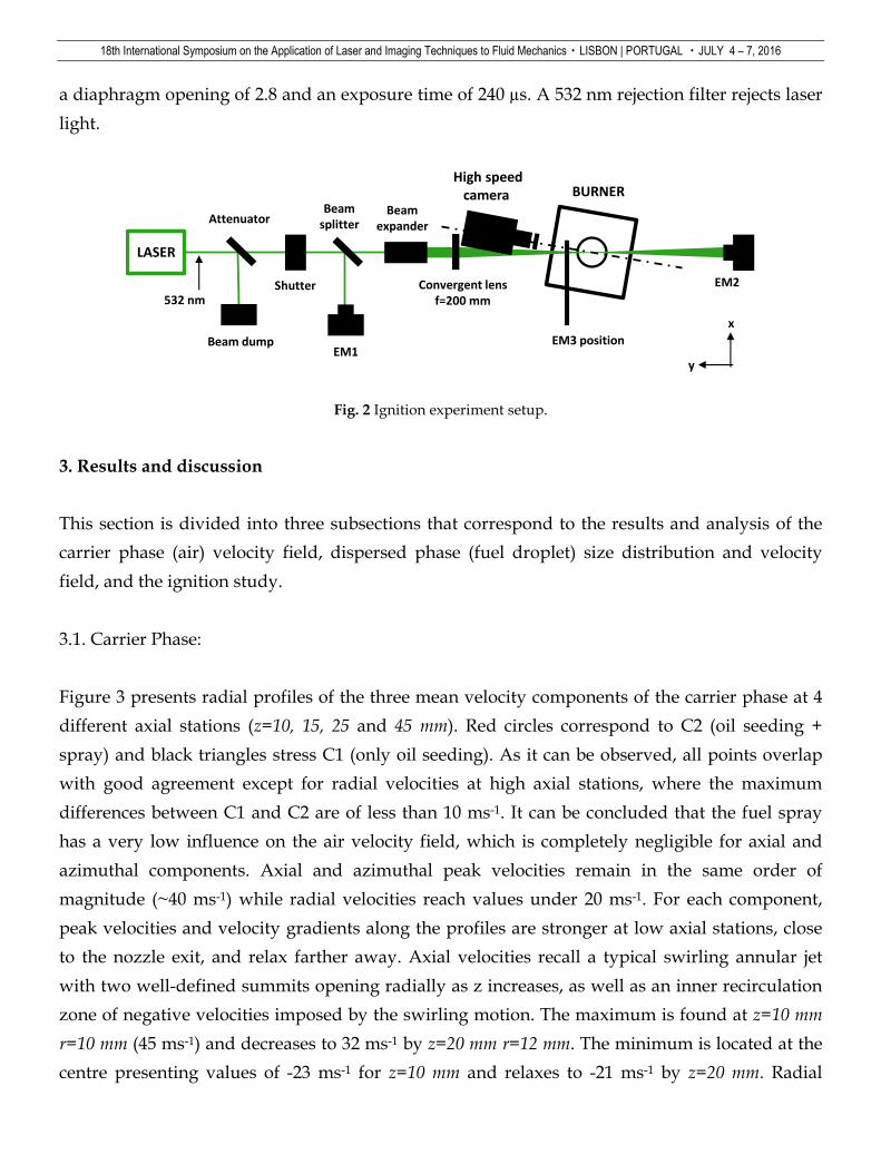
a diaphragm opening of 2.8 and an exposure time of 240 µs. A 532 nm rejection filter rejects laser
light.
Fig. 2 Ignition experiment setup.
3. Results and discussion
This section is divided into three subsections that correspond to the results and analysis of the
carrier phase (air) velocity field, dispersed phase (fuel droplet) size distribution and velocity
field, and the ignition study.
3.1. Carrier Phase:
Figure 3 presents radial profiles of the three mean velocity components of the carrier phase at 4
different axial stations (z=10, 15, 25 and 45 mm). Red circles correspond to C2 (oil seeding +
spray) and black triangles stress C1 (only oil seeding). As it can be observed, all points overlap
with good agreement except for radial velocities at high axial stations, where the maximum
differences between C1 and C2 are of less than 10 ms-1. It can be concluded that the fuel spray
has a very low influence on the air velocity field, which is completely negligible for axial and
azimuthal components. Axial and azimuthal peak velocities remain in the same order of
magnitude (~40 ms-1) while radial velocities reach values under 20 ms-1. For each component,
peak velocities and velocity gradients along the profiles are stronger at low axial stations, close
to the nozzle exit, and relax farther away. Axial velocities recall a typical swirling annular jet
with two well-defined summits opening radially as z increases, as well as an inner recirculation
zone of negative velocities imposed by the swirling motion. The maximum is found at z=10 mm
r=10 mm (45 ms-1) and decreases to 32 ms-1 by z=20 mm r=12 mm. The minimum is located at the
centre presenting values of -23 ms-1 for z=10 mm and relaxes to -21 ms-1 by z=20 mm. Radial
BURNER
LASER
Attenuator
532 nm
Beam dumpEM1
Shutter
Beamsplitter
Beamexpander
Convergent lensf=200 mm
EM2
High speed camera
EM3 position
y
x

18th International Symposium on the Application of Laser and Imaging Techniques to Fluid Mechanics・LISBON | PORTUGAL ・JULY 4 – 7, 2016
velocity profiles show a radially opening jet with higher velocities at low axial stations. For r<10
mm, one can observe very small centripetal velocities at every axial station which are generated
by low pressures in the inner recirculation zone. Below z=25 mm, radial velocities outside the air
jet (r>15 mm) are pointing towards the centre describing the start of the well-known outer
recirculation zone (ORZ), which is characteristic of this kind of burners, as shown by Providakis
T, Paulhiac D and Hannebique G. Azimuthal velocities follow the same behaviour as the axial
velocities, presenting maximum values at low axial stations that move outwards radially with
increasing z.
Fig. 3 Mean components of air velocity flow for non-reactive conditions. Black triangles: C1 (seeding oil without fuel
spray). Red circles: C2 (seeding oil with fuel spray).
Velocity fluctuations are expressed in Fig. 4 (C1) in terms of the turbulent kinetic energy (k),
which is calculated following equation 5:
𝑘 = 1
2((𝑢′1)2 + (𝑢′2)2 + (𝑢′3)2) . (5)
The maximum turbulent energy (~550 m2s-2) is found at low axial stations, in the region where
the air enters the chamber, and follows the same pattern as the axial and azimuthal velocities,
with peaks diffusing radially with increasing axial stations. Given that energetic velocity
fluctuations enhance mixing and that all droplets enter the region of maximum k directly after
atomisation, their trajectories will be strongly influenced by the airflow and all size-classes will
coexist resulting in a heterogeneous droplet size distribution. Zones outside the external shear
layer of the air jet show blue colours indicating the lowest k measured values (<100 m2s-2). Air
velocities appear to be very low in this region. However, it is a characteristic area of these

18th International Symposium on the Application of Laser and Imaging Techniques to Fluid Mechanics・LISBON | PORTUGAL ・JULY 4 – 7, 2016
burners presenting vortices that enclose burnt gases and/or fuel vapour between the air jet
border and the burner walls and base.
Fig. 4 Turbulent kinetic energy of the air in non-reactive conditions (C1)
3.2. Dispersed phase:
The injector used in this experiment yields a hollow cone with droplet sizes ranging from 2 to 80
µm as displayed on the two histograms for two different points in Fig. 5 (left). The central region
contains a very low quantity of droplets due to the centrifugal movement imposed by the
swirling air motion. Droplets are expelled from the atomiser under a cone with an 80° opening,
following a direction that will carry them suddenly into the high velocity and high k area where
they interact with the airflow. The smallest droplets follow more closely the air velocity field
provided their low Stokes number while bigger droplets take more time to adapt to the imposed
aerodynamic conditions. However, all size-classes follow evenly the same presence pattern
along the burner in order to leave a very underpopulated central region and a high population
along the borders of the spray as presented in Fig. 5 (middle). Droplets have been divided into 7
size-classes: [0-10], [10-20], [20-30], [30-40], [40-50], [50-60] and [60-70] µm. Figure 5 (middle)
displays the rate of droplet counts for different size-classes along the burner. Droplets between
10 and 30 µm compose the predominant classes at any location. At z=10 mm, small droplets
appear to locate preferentially in a slightly outer region than big droplets. This behaviour is
inversed for higher axial stations. It is worth noting that the vertical axis in Fig. 5 (middle) is
different for each axial station because there are far fewer droplets at higher axial stations. Figure
5 (right) presents the mean droplet diameter (D10) profiles along the 4 axial stations, yielding
18th International Symposium on the Application of Laser and Imaging Techniques to Fluid Mechanics・LISBON | PORTUGAL ・JULY 4 – 7, 2016
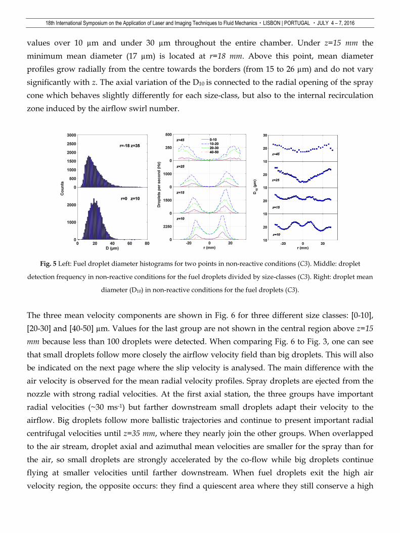
values over 10 µm and under 30 µm throughout the entire chamber. Under z=15 mm the
minimum mean diameter (17 µm) is located at r=18 mm. Above this point, mean diameter
profiles grow radially from the centre towards the borders (from 15 to 26 µm) and do not vary
significantly with z. The axial variation of the D10 is connected to the radial opening of the spray
cone which behaves slightly differently for each size-class, but also to the internal recirculation
zone induced by the airflow swirl number.
Fig. 5 Left: Fuel droplet diameter histograms for two points in non-reactive conditions (C3). Middle: droplet
detection frequency in non-reactive conditions for the fuel droplets divided by size-classes (C3). Right: droplet mean
diameter (D10) in non-reactive conditions for the fuel droplets (C3).
The three mean velocity components are shown in Fig. 6 for three different size classes: [0-10],
[20-30] and [40-50] µm. Values for the last group are not shown in the central region above z=15
mm because less than 100 droplets were detected. When comparing Fig. 6 to Fig. 3, one can see
that small droplets follow more closely the airflow velocity field than big droplets. This will also
be indicated on the next page where the slip velocity is analysed. The main difference with the
air velocity is observed for the mean radial velocity profiles. Spray droplets are ejected from the
nozzle with strong radial velocities. At the first axial station, the three groups have important
radial velocities (~30 ms-1) but farther downstream small droplets adapt their velocity to the
airflow. Big droplets follow more ballistic trajectories and continue to present important radial
centrifugal velocities until z=35 mm, where they nearly join the other groups. When overlapped
to the air stream, droplet axial and azimuthal mean velocities are smaller for the spray than for
the air, so small droplets are strongly accelerated by the co-flow while big droplets continue
flying at smaller velocities until farther downstream. When fuel droplets exit the high air
velocity region, the opposite occurs: they find a quiescent area where they still conserve a high

18th International Symposium on the Application of Laser and Imaging Techniques to Fluid Mechanics・LISBON | PORTUGAL ・JULY 4 – 7, 2016
axial velocity. This is more remarkable at low axial stations and for big droplets, and it is also
observed for the azimuthal component to a lesser extent. Differences of more than 20 ms-1 are
observed between the [0-10] group and the [40-50] group. The other size-classes present the same
trends, but they are not presented here in order to facilitate the comprehension of the figure. The
behaviour of [50-60] and [60-70] groups is very close to the [40-50] group, but, as they contain
less droplets, they are not presented. During their travel, droplets experience important slip
velocities, which certainly control the evaporation process and, therefore, vapour production
and local air-to-fuel ratio. Slip velocities correspond to the relative velocities between droplets
and the airflow. They are a key parameter in two-phase combustion.
Fig. 6 Mean components of fuel droplet velocity in non-reactive conditions (C3) separated in three size-classes.
Purple triangles represent the [0-10] µm group, green squares the [20-30] µm group and red circles the [40-50] µm
group.
In order to calculate the mean slip velocity (s) for each point, the spray mean velocity field was
subtracted to the air mean velocity field component by component, group by group, as equation
6 stresses:
𝑠 = ((𝑈1𝑎𝑖𝑟 − 𝑈1𝑓𝑢𝑒𝑙), (𝑈2𝑎𝑖𝑟 − 𝑈2𝑓𝑢𝑒𝑙), (𝑈3𝑎𝑖𝑟 − 𝑈3𝑓𝑢𝑒𝑙)) . (6)
The magnitude of the resulting vectors is displayed in Fig. 7 for the same three size-classes as
before. Mean slip velocities are more important close to the nozzle exit and for big droplets. The
[0-10] group experiences lower values than the others but these are not negligible. Above z=15
mm, peaks remain under 20 ms-1. For the [40-50] group, mean slip velocities grow up to 38 ms-1
and values above 20 ms-1 can be found below z=25 mm. The maximum slip velocities are found

18th International Symposium on the Application of Laser and Imaging Techniques to Fluid Mechanics・LISBON | PORTUGAL ・JULY 4 – 7, 2016
on the borders of the spray, at the same radial positions as droplet peak radial velocities. Here,
droplets still have high axial velocities and they have exited the high air velocity region. In the
centre, al low z, strong slip velocities are also observed. They are caused by the descending
recirculating air flowing against the rising droplets. Vapour produced at the centre will be
recirculated downwards along the centre. There is a minimum mean slip velocity for all size-
classes above z=10 mm placed over regions of medium turbulence intensity, where velocity
fluctuations are 40% of mean velocities and where k is maximal. Provided that large droplets
present far greater slip velocities than small droplets at many points along the profiles (>20 ms-1),
they will experience high evaporation rates. As they carry most of the fuel mass, they will
contribute significantly to fuel vapour production and repartition along the burner. The vapour
produced at the borders finds a region with low values of air velocity and may be entrained into
the ORZ.
Fig. 7 Mean slip velocity magnitude in non-reactive conditions for three size-classes. Purple triangles represent the
[0-10] µm group, green squares the [20-30] µm group and red circles the [40-50] µm group.
3.3. Ignition:
Ignition probability is strongly influenced by the aerodynamics of the flow inside the chamber
and by fuel droplet and vapour distribution. Air and droplet velocity fields have been discussed
on the previous sections. Fuel vapour is produced at a higher rate in high slip velocity regions,
and it will be transported by the airflow. Furthermore, there is a greater liquid presence in areas
covered by big droplet pathways, so the injection pressure, the injector design and the spray
angle play a very important role too. The coupling of these parameters plus the temperature
18th International Symposium on the Application of Laser and Imaging Techniques to Fluid Mechanics・LISBON | PORTUGAL ・JULY 4 – 7, 2016
distribution along the burner will directly impact on the ignition probability. Results also show
that the flame kernel follows different ways and different propagation directions in function of
local mixture properties and instantaneous airflow velocities. This may influence even more the
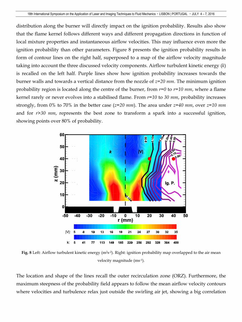
ignition probability than other parameters. Figure 8 presents the ignition probability results in
form of contour lines on the right half, superposed to a map of the airflow velocity magnitude
taking into account the three discussed velocity components. Airflow turbulent kinetic energy (k)
is recalled on the left half. Purple lines show how ignition probability increases towards the
burner walls and towards a vertical distance from the nozzle of z=20 mm. The minimum ignition
probability region is located along the centre of the burner, from r=0 to r=10 mm, where a flame
kernel rarely or never evolves into a stabilised flame. From r=10 to 30 mm, probability increases
strongly, from 0% to 70% in the better case (z=20 mm). The area under z=40 mm, over z=10 mm
and for r>30 mm, represents the best zone to transform a spark into a successful ignition,
showing points over 80% of probability.
Fig. 8 Left: Airflow turbulent kinetic energy (m2s-2). Right: ignition probability map overlapped to the air mean
velocity magnitude (ms-1).
The location and shape of the lines recall the outer recirculation zone (ORZ). Furthermore, the
maximum steepness of the probability field appears to follow the mean airflow velocity contours
where velocities and turbulence relax just outside the swirling air jet, showing a big correlation

18th International Symposium on the Application of Laser and Imaging Techniques to Fluid Mechanics・LISBON | PORTUGAL ・JULY 4 – 7, 2016
between these parameters and ignition. At axial stations close to z=5 mm and for r<5 mm, 1 over
10 sparks will succeed to generate a stabilised flame by a different mechanism than the others.
The air velocity here is negative due to the inner recirculation zone (IRZ) and the flame kernel
will be directed into the spray cone where it will certainly find regions rich in fuel but also a
strong shear and velocities that will intensely stretch it and convect it upwards into poor regions.
Figures 9 to 12 present kernel propagation sequences recorded with the high-speed Phantom
V2512 camera. Although images are acquired every 250 µs, each image here is 500 µs after the
previous one because no such temporal resolution is needed for this purpose. It is worth noting
that the camera is recording at an angle that enables the perception of the azimuthal kernel
displacement but privileges the movement perception in the XZ plane. The spark saturates some
pixels that present high intensities in all images before 3 ms after the shutter opening, and stays
visible in the other ones. Two points from the ignition interrogation mesh have been selected to
be analysed here (red dots in Fig. 8). Figure 9 shows the development and movement of a kernel
for a successful ignition at x=40; z=40 mm. This point has an ignition probability of 67%. The first
image corresponds to the flame kernel 160 µs after the spark breakdown (shutter opening). It
seems to be cut at the left because the camera has no optic access to the region close to the quartz
window (it is hidden by the burner column). The following images show the flame kernel
thermal expansion and global downward movement, trapped by the ORZ and moving towards
the spray through the slow velocity region. After 4 ms, punctual growth of pixel intensities
reveals an increase in heat release.
Fig. 9 Successful ignition. Evolution of the kernel position for laser focusing point at x=40 mm, z=40 mm.
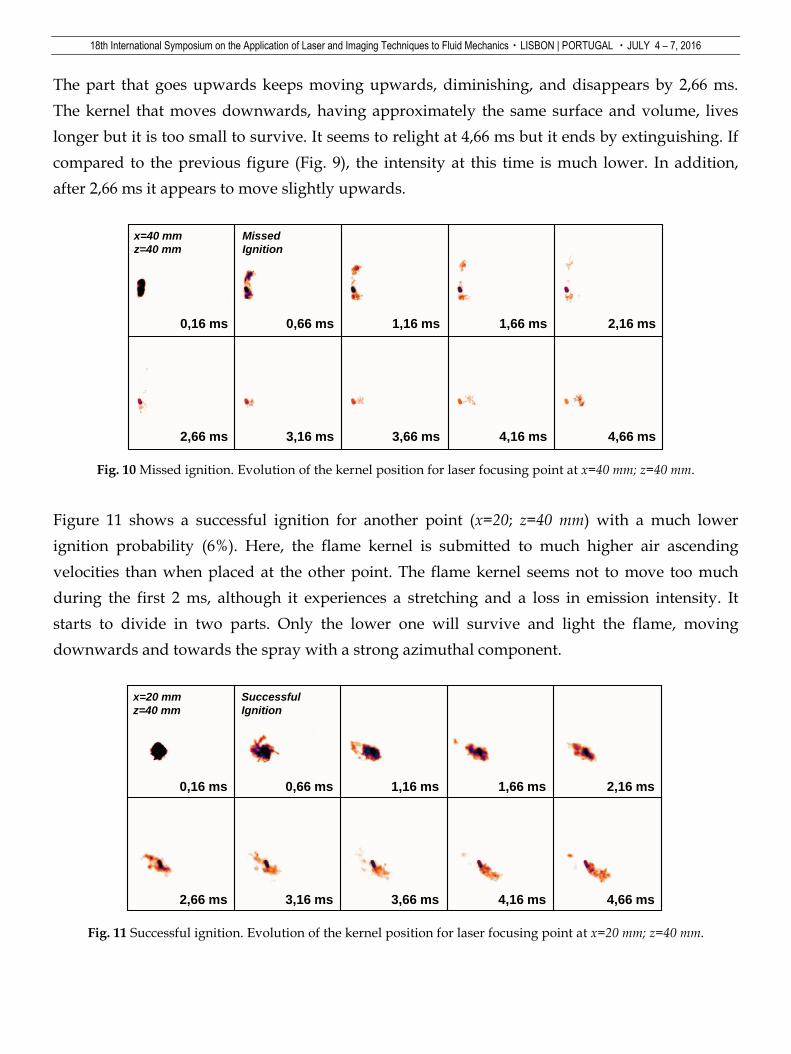
Figure 10 presents an unsuccessful ignition for the same point (x=40; z=40 mm). Since the first
image one can see the thermal expansion divides the flame kernel in two parts of similar sizes.
0,16 ms 0,66 ms 1,16 ms 1,66 ms 2,16 ms
2,66 ms 3,16 ms 3,66 ms 4,16 ms 4,66 ms
x=40 mm
z=40 mm
Successful
Ignition
18th International Symposium on the Application of Laser and Imaging Techniques to Fluid Mechanics・LISBON | PORTUGAL ・JULY 4 – 7, 2016
The part that goes upwards keeps moving upwards, diminishing, and disappears by 2,66 ms.
The kernel that moves downwards, having approximately the same surface and volume, lives
longer but it is too small to survive. It seems to relight at 4,66 ms but it ends by extinguishing. If
compared to the previous figure (Fig. 9), the intensity at this time is much lower. In addition,
after 2,66 ms it appears to move slightly upwards.
Fig. 10 Missed ignition. Evolution of the kernel position for laser focusing point at x=40 mm; z=40 mm.
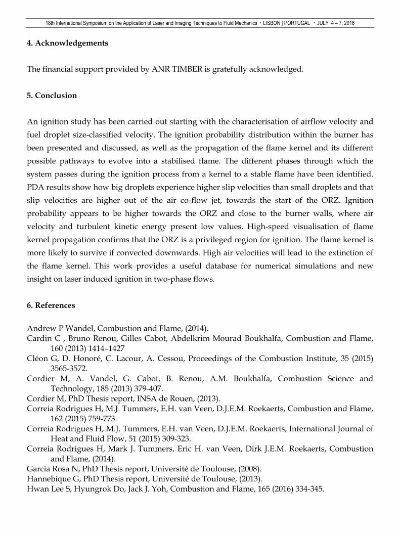
Figure 11 shows a successful ignition for another point (x=20; z=40 mm) with a much lower
ignition probability (6%). Here, the flame kernel is submitted to much higher air ascending
velocities than when placed at the other point. The flame kernel seems not to move too much
during the first 2 ms, although it experiences a stretching and a loss in emission intensity. It
starts to divide in two parts. Only the lower one will survive and light the flame, moving
downwards and towards the spray with a strong azimuthal component.
Fig. 11 Successful ignition. Evolution of the kernel position for laser focusing point at x=20 mm; z=40 mm.
0,16 ms 0,66 ms 1,16 ms 1,66 ms 2,16 ms
2,66 ms 3,16 ms 3,66 ms 4,16 ms 4,66 ms
x=40 mm
z=40 mm
Missed
Ignition
0,16 ms 0,66 ms 1,16 ms 1,66 ms 2,16 ms
2,66 ms 3,16 ms 3,66 ms 4,16 ms 4,66 ms
x=20 mm
z=40 mm
Successful
Ignition

18th International Symposium on the Application of Laser and Imaging Techniques to Fluid Mechanics・LISBON | PORTUGAL ・JULY 4 – 7, 2016
Figure 12 shows two series of images for two missed ignitions at the same point (x=20; z=40 mm),
where kernels are clearly convected upwards losing any chance to find propitious conditions to
survive. The sequences show that the quicker a kernel moves upwards, the quicker it diminishes.
The present kernel evolution sequences are representative of the majority of the observed cases.
It is only at small values of r, in the IRZ, that the kernel is sucked downwards towards the spray
and reconvected upwards very violently by the air co-flow, rarely being successfully ignited.
Fig. 12 Missed ignitions. Evolution of the kernel position for laser focusing point at x=20 mm; z=40 mm.
If the flame kernel survives enough time without being convected upwards and finds propitious
regions to grow and produce more and more chemical reactions, the complete burner ignition
takes some time and passes through different phases. These phases are captured by the high-
speed images and by the pressure signal from the chamber, and are illustrated in Fig. 13. They
can be classified into the following:
Kernel growth and movement
Developed kernel settling in the ORZ
Spray light-around
Maximum heat release
Flame attachment to nozzle
Flame lifting
The pressure signal shows strong pressure variations due to the spark shockwave and noise
from 0 ms to 15 ms after breakdown. During this time, the flame kernel moves through the
chamber and grows into a little weak flame that often touches the opposite wall to descend into
0,16 ms 0,66 ms 1,16 ms 1,66 ms 2,16 ms
x=20 mm
z=40 mm
Missed
Ignition
0,16 ms 0,66 ms 1,16 ms 1,66 ms 2,16 ms
x=20 mm
z=40 mm
Missed
Ignition

18th International Symposium on the Application of Laser and Imaging Techniques to Fluid Mechanics・LISBON | PORTUGAL ・JULY 4 – 7, 2016
the ORZ at about 20 ms after breakdown. At this moment, pressure starts to increase in the
chamber and the spray light-around starts, following an anti-clockwise movement imposed by
the swirling motion. A pressure peak is reached when the whole spray has been lighted, 42 ms
after breakdown. This moment is coupled to the maximum heat release observed in the images
and may be caused by fuel vapour accumulation. This stage is followed by a noisy conical flame
attached to the spray cone that generates strong pressure oscillations and becomes unstable to
disappear at about 70 ms after breakdown. After this, the pressure signal presents oscillations
with lower frequencies and decreasing amplitudes. When the conical intense flame disappears, it
leaves a lifted, lean and stable blue flame, as the one shown in Fig. 1 (here, the last image at 124
ms). Characteristic times vary from one event to another but Fig. 13 is representative of the
process.
Fig. 13 Evolution of the pressure signal inside the chamber during an ignition event. Images of the different ignition
phases at instants from 1 to 125 ms after the energy deposition.
1 ms 21 ms 33 ms 42 ms 54 ms
63 ms 69 ms 73 ms 98 ms 124 ms
18th International Symposium on the Application of Laser and Imaging Techniques to Fluid Mechanics・LISBON | PORTUGAL ・JULY 4 – 7, 2016
4. Acknowledgements
The financial support provided by ANR TIMBER is gratefully acknowledged.
5. Conclusion
An ignition study has been carried out starting with the characterisation of airflow velocity and
fuel droplet size-classified velocity. The ignition probability distribution within the burner has
been presented and discussed, as well as the propagation of the flame kernel and its different
possible pathways to evolve into a stabilised flame. The different phases through which the
system passes during the ignition process from a kernel to a stable flame have been identified.
PDA results show how big droplets experience higher slip velocities than small droplets and that
slip velocities are higher out of the air co-flow jet, towards the start of the ORZ. Ignition
probability appears to be higher towards the ORZ and close to the burner walls, where air
velocity and turbulent kinetic energy present low values. High-speed visualisation of flame
kernel propagation confirms that the ORZ is a privileged region for ignition. The flame kernel is
more likely to survive if convected downwards. High air velocities will lead to the extinction of
the flame kernel. This work provides a useful database for numerical simulations and new
insight on laser induced ignition in two-phase flows.
6. References
Andrew P Wandel, Combustion and Flame, (2014). Cardin C , Bruno Renou, Gilles Cabot, Abdelkrim Mourad Boukhalfa, Combustion and Flame,
160 (2013) 1414–1427 Cléon G, D. Honoré, C. Lacour, A. Cessou, Proceedings of the Combustion Institute, 35 (2015)
3565-3572. Cordier M, A. Vandel, G. Cabot, B. Renou, A.M. Boukhalfa, Combustion Science and
Technology, 185 (2013) 379-407. Cordier M, PhD Thesis report, INSA de Rouen, (2013). Correia Rodrigues H, M.J. Tummers, E.H. van Veen, D.J.E.M. Roekaerts, Combustion and Flame,
162 (2015) 759-773. Correia Rodrigues H, M.J. Tummers, E.H. van Veen, D.J.E.M. Roekaerts, International Journal of
Heat and Fluid Flow, 51 (2015) 309-323. Correia Rodrigues H, Mark J. Tummers, Eric H. van Veen, Dirk J.E.M. Roekaerts, Combustion
and Flame, (2014). Garcia Rosa N, PhD Thesis report, Université de Toulouse, (2008). Hannebique G, PhD Thesis report, Université de Toulouse, (2013). Hwan Lee S, Hyungrok Do, Jack J. Yoh, Combustion and Flame, 165 (2016) 334-345.

18th International Symposium on the Application of Laser and Imaging Techniques to Fluid Mechanics・LISBON | PORTUGAL ・JULY 4 – 7, 2016
Kourmatzis A, P.X. Pham, A.R. Masri, Combustion and Flame, (2015). Lawes M, Y. Lee, A. S. Mokhtar and R. Woolley, Combustion Science and Technology, 180 (2).
pp. 296-313. Letty C, Epaminondas Mastorakos, Assaad R. Masri, Mrinal Juddoo, William O’Loughlin,
Experimental Thermal and Fluid Science, 43 (2012) 47–54. Linassier G, PhD Thesis report, Université de Toulouse, (2012). Morkous S Mansour, Issam Alkhesho, Suk Ho Chung, Experimental Thermal and Fluid Science,
(2015). Mulla IA, Satyanarayanan R. Chakravarthy, Nedunchezhian Swaminathan, Ramanarayanan
Balachandran, Combustion and Flame, 000 (2015) 1–16. Nicolia C, Denet B., Haldenwang P., Combustion and Flame, 000 (2015) 1–14. Paulhiac D, PhD Thesis report, Université de Toulouse, (2015). Providakis T, PhD Thesis report, Ecole Centrale Paris, (2013). Sánchez AL, Javier Urzay, Amable Liñán, Proceedings of the Combustion Institute, 35 (2015)
1549–1577.
Related Documents