http://www.iaeme.com/IJMET/index.asp 1629 [email protected] International Journal of Mechanical Engineering and Technology (IJMET) Volume 8, Issue 8, August 2017, pp. 1629–1641, Article ID: IJMET_08_08_177 Available online at http://www.iaeme.com/IJMET/issues.asp?JType=IJMET&VType=8&IType=8 ISSN Print: 0976-6340 and ISSN Online: 0976-6359 © IAEME Publication Scopus Indexed EXPERIMENTAL INVESTIGATION ON FRICTION STIR WELDED ALUMINIUM –SCILICON ALLOY S. Thirumavalavan Assistant Professor, Department of Mechanical Engineering, Bharath University, Chennai, Tamilnadu, India R. Sabarish Assistant Professor, Department of Mechanical Engineering, Bharath University, Chennai, Tamilnadu, India U. Ganesan Assistant Professor, Department of Mechanical Engineering, Jawahar Engineering College, Chennai, Tamilnadu, India ABSTRACT Friction Stir Welding has been recognized as a potential candidate for joining of non-ferrous materials which found its application in transportation, automobile, ship building and aerospace industries. The aim of the present study is to investigate the flow of material around different tool pin profiles. Tensile strength tests and hardness tests are to be carried out on aluminium – silicon alloy to determine the mechanical properties of weld. The flow of the material around the pin can be determined by tracing the flow lines. The Tensile failure characteristics of the weld are to be discussed. The friction stir welding is done on AA6082 alloy, an Al-Mg-Si alloy. A few of silicon particles remain as such in the aluminium matrix and the remaining forms Mg 2 Si compounds. The Mg 2 Si compounds can be clearly seen as a black phase when viewed under optical microscope. During FSW, coarse grains get refined into finer grains and get deposited in the stir zone. Morphology, Size and Shape variation of grains are helpful in classifying the various zones of friction stir welding. Friction stir welding of aluminium is widely applied in marine, aerospace, rail, automotive and some other transportation industries. Friction Stir Welding of AA6082 Key words: silicon alloy, Friction stir welding, CNC Lathe, fabrication. Cite this Article: S. Thirumavalavan, R. Sabarish, U. Ganesan, Experimental Investigation on Friction Stir Welded Aluminium–Scilicon Alloy, International Journal of Mechanical Engineering and Technology 8(8), 2017, pp. 1629–1641. http://www.iaeme.com/IJMET/issues.asp?JType=IJMET&VType=8&IType=8

Welcome message from author
This document is posted to help you gain knowledge. Please leave a comment to let me know what you think about it! Share it to your friends and learn new things together.
Transcript

http://www.iaeme.com/IJMET/index.asp 1629 [email protected]
International Journal of Mechanical Engineering and Technology (IJMET)
Volume 8, Issue 8, August 2017, pp. 1629–1641, Article ID: IJMET_08_08_177
Available online at http://www.iaeme.com/IJMET/issues.asp?JType=IJMET&VType=8&IType=8
ISSN Print: 0976-6340 and ISSN Online: 0976-6359
© IAEME Publication Scopus Indexed
EXPERIMENTAL INVESTIGATION ON
FRICTION STIR WELDED ALUMINIUM
–SCILICON ALLOY
S. Thirumavalavan
Assistant Professor, Department of Mechanical Engineering,
Bharath University, Chennai, Tamilnadu, India
R. Sabarish
Assistant Professor, Department of Mechanical Engineering,
Bharath University, Chennai, Tamilnadu, India
U. Ganesan
Assistant Professor, Department of Mechanical Engineering,
Jawahar Engineering College, Chennai, Tamilnadu, India
ABSTRACT
Friction Stir Welding has been recognized as a potential candidate for joining of
non-ferrous materials which found its application in transportation, automobile, ship
building and aerospace industries. The aim of the present study is to investigate the
flow of material around different tool pin profiles. Tensile strength tests and hardness
tests are to be carried out on aluminium – silicon alloy to determine the mechanical
properties of weld. The flow of the material around the pin can be determined by
tracing the flow lines. The Tensile failure characteristics of the weld are to be
discussed.
The friction stir welding is done on AA6082 alloy, an Al-Mg-Si alloy. A few of
silicon particles remain as such in the aluminium matrix and the remaining forms
Mg2Si compounds. The Mg2Si compounds can be clearly seen as a black phase when
viewed under optical microscope. During FSW, coarse grains get refined into finer
grains and get deposited in the stir zone. Morphology, Size and Shape variation of
grains are helpful in classifying the various zones of friction stir welding.
Friction stir welding of aluminium is widely applied in marine, aerospace, rail,
automotive and some other transportation industries. Friction Stir Welding of AA6082
Key words: silicon alloy, Friction stir welding, CNC Lathe, fabrication.
Cite this Article: S. Thirumavalavan, R. Sabarish, U. Ganesan, Experimental
Investigation on Friction Stir Welded Aluminium–Scilicon Alloy, International
Journal of Mechanical Engineering and Technology 8(8), 2017, pp. 1629–1641.
http://www.iaeme.com/IJMET/issues.asp?JType=IJMET&VType=8&IType=8

S. Thirumavalavan, R. Sabarish, U. Ganesan
http://www.iaeme.com/IJMET/index.asp 1630 [email protected]
1. INTRODUCTION
1.1. Need for Study
The need for study is to understand the complete process of friction stir welding; the forces
involved in welding the material; defects caused during friction stir welding; and process
parameters involved. This study has given a clear idea about the FSW process behaviour,
setup and procedure of welding. Both mechanical and microstructural tests which were done
on the specimen and its principle of operation was also studied.
1.2. Objective of the Project
The main objective of the project is to friction stir weld the Al-Si alloy using a conventional
Vertical Milling machine; to carry out the microstructural investigation in Optical Microscope
and to determine the flow of material around the tool pin profile by interpreting the
microstructural analysis data; to conduct mechanical tests on the specimen (Tensile Test and
Micro-Vickers Hardness Test) to establish the mechanically sound weld and to report
microstructurally and mechanically optimal weld.
2. MATERIAL SELECTION
2.1. Plate Material
The main aim of the project work is the microstructural investigation i.e., analysing the
microstructures at various zones of FSW. Classifying various region of FSW is a tedious
process. It requires a deep knowledge in material science[1-5].
In case of pure aluminium or Al alloys with same microstructure, this investigation
becomes much tougher. In such cases, the presence of second phase additives will act as
medium to classify the various zones of FSW.
2.2. Silicon
Silicon was chosen as a second phase additive in this project. Silicon is naturally added to the
Aluminium alloys to improve their strength. Silicon remains dispersed in the aluminium
matrix without undergoing any atomic level interaction.
Silicon is a high thermal conductivity material and also it is cheap. These advantages
make silicon a preferable additive in aluminium alloys.
But the main problem with the Silicon is that it is a brittle material. Excessive Silicon in
the material turns a ductile material into a brittle one. So that in almost all aluminium alloys
Silicon content is kept in very low percentages. Figure 1 shows the lump of silicon
powders[6-9].
Figure 1 Silicon powders

Experimental Investigation on Friction Stir Welded Aluminium–Scilicon Alloy
http://www.iaeme.com/IJMET/index.asp 1631 [email protected]
This property of silicon makes it poor alloying elements for thin sections like plates,
sheets, flats etc. If Silicon is present > 10%, it can’t be rolled into a sheet.
If it is at 2-10%, rolled sheets with cracks, voids and residual stresses will be formed. If
Silicon is present < 2%, rolled sheets free of cracks and voids will be formed.
For this project, the presence of high level of Silicon is preferable because it helps in
accurate differentiation of the zones. At the same time, the presence of lower percentage of
Silicon is required for the specimen to be in sheet form. A compromise must be done while
choosing between these two factors. A material must be chosen in such a way that it has
sufficient amount of silicon to classify the zones and to roll the specimen into a sheet.
2.3. Tool Material – M2 Steel
M2 is a high-speed steel in tungsten–molybdenum series. The carbides in it are small and
evenly distributed. It has high wear resistance. After heat treatment, its hardness is the same
as T1 grade tool steel, but its bending strength can reach 4700 MPa, and its toughness and
thermoplasticity are higher than T1 by 50%. It is usually used to manufacture a variety of
tools, such as drill bits, taps and reamers. Its decarburization sensitivity is a little bit high.
3. FABRICATION AND HARDENING OF TOOL
3.1. Fabrication of M2 Tool Steel
The machining was done and the metal was removed from the rod by CNC lathe machine.
The machine was operated at a constant rotational speed throughout the process. The final
finishing to the job was given by cylindrical grinding.
Shaping of M2 tool steels can be carried out using grinding methods. However, they have
poor grinding capability and hence they are regarded as "medium" machinability tool steel
under annealed conditions. The machinability of these steels is only 50% of that of the easily
machinable W group or water hardening tool steels[10-14].
3.2. Heat Treatment of M2 Tool Steel
M2 tool steels were heat treated to achieve Rockwell harness value in range of 55 – 60. They
were pre-heated prior to hardening at 2610°C (4730°F) followed by rapid heating from
2610°C (4730°F) to 3960°C (7160°F). These steels were then cooled for 3 to 5 min and
quenched in air, salt bath or oil.
Annealing: M2 tool steels were annealed at 2925°C (5297°F) and cooled at 72°C (162°F) per
hour or even less.
Tempering: M2 steels were tempered at 1890°C (3434°F) to obtain Rockwell C hardness
from 60 to 65.
Hardening: Finally, M2 steels were hardened by heat treatment and quenching.
Figure 2 Fabricated and Hardened Tool
S. Thirumavalavan, R. Sabarish, U. Ganesan
http://www.iaeme.com/IJMET/index.asp 1632 [email protected]
3.3. Steps to Harden M2 Tool Steel
Hardening of a tool steel is an important process of tool making. The hardening must be
performed carefully otherwise it leads to tool failure. A tool once hardened cannot be de-
hardened. The fabricated and hardened tools used in this work are shown in Figure 2 and 3.
The following are the steps that were followed while hardening the tool steel.
Hardening steel causes the structure of carbon to crystallize, similar to the way coal or
graphite changes to diamond under the heat and pressure within the earth. Without other
metals alloyed with it, steel to be hardened needs to have a carbon content of about 1.0
percent. This kind of steel is called high-carbon steel or tool steel.
Heat the entire piece of tool slowly at first. Then, concentrate the heat on the area that has
to be hardened, until that area glows red hot.
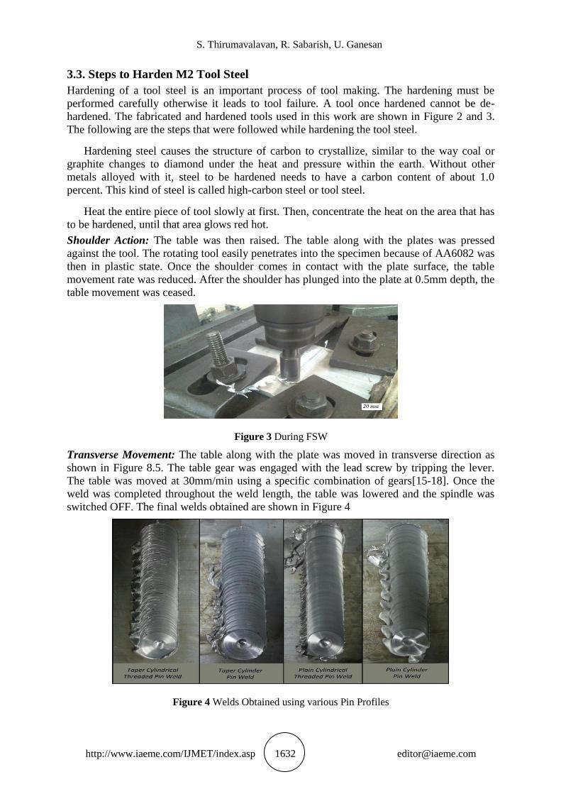
Shoulder Action: The table was then raised. The table along with the plates was pressed
against the tool. The rotating tool easily penetrates into the specimen because of AA6082 was
then in plastic state. Once the shoulder comes in contact with the plate surface, the table
movement rate was reduced. After the shoulder has plunged into the plate at 0.5mm depth, the
table movement was ceased.
Figure 3 During FSW
Transverse Movement: The table along with the plate was moved in transverse direction as
shown in Figure 8.5. The table gear was engaged with the lead screw by tripping the lever.
The table was moved at 30mm/min using a specific combination of gears[15-18]. Once the
weld was completed throughout the weld length, the table was lowered and the spindle was
switched OFF. The final welds obtained are shown in Figure 4
Figure 4 Welds Obtained using various Pin Profiles
Experimental Investigation on Friction Stir Welded Aluminium–Scilicon Alloy
http://www.iaeme.com/IJMET/index.asp 1633 [email protected]
3.4. Post Weld Surface Cleaning
The burrs on the weld surface were removed by using chisels. The weld marks were then
removed by polishing it with rough emery sheet. The surface of the weld was then cleaned
with cleansing solution and it is wiped off with a dry cloth. The welds were ready for testing.
4. MICROSTRUCTURAL INVESTIGATION MOUNTING OF
SPECIMEN
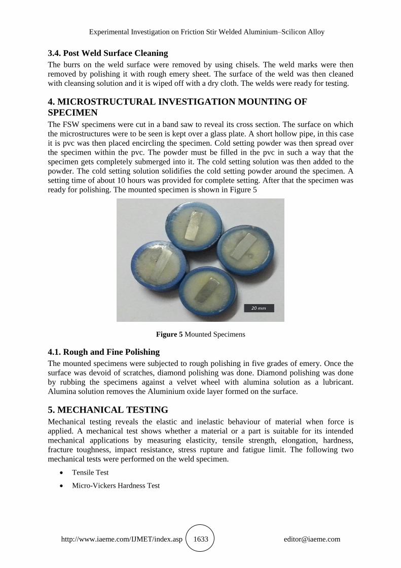
The FSW specimens were cut in a band saw to reveal its cross section. The surface on which
the microstructures were to be seen is kept over a glass plate. A short hollow pipe, in this case
it is pvc was then placed encircling the specimen. Cold setting powder was then spread over
the specimen within the pvc. The powder must be filled in the pvc in such a way that the
specimen gets completely submerged into it. The cold setting solution was then added to the
powder. The cold setting solution solidifies the cold setting powder around the specimen. A
setting time of about 10 hours was provided for complete setting. After that the specimen was
ready for polishing. The mounted specimen is shown in Figure 5
Figure 5 Mounted Specimens
4.1. Rough and Fine Polishing
The mounted specimens were subjected to rough polishing in five grades of emery. Once the
surface was devoid of scratches, diamond polishing was done. Diamond polishing was done
by rubbing the specimens against a velvet wheel with alumina solution as a lubricant.
Alumina solution removes the Aluminium oxide layer formed on the surface.
5. MECHANICAL TESTING
Mechanical testing reveals the elastic and inelastic behaviour of material when force is
applied. A mechanical test shows whether a material or a part is suitable for its intended
mechanical applications by measuring elasticity, tensile strength, elongation, hardness,
fracture toughness, impact resistance, stress rupture and fatigue limit. The following two
mechanical tests were performed on the weld specimen.
Tensile Test
Micro-Vickers Hardness Test
S. Thirumavalavan, R. Sabarish, U. Ganesan
http://www.iaeme.com/IJMET/index.asp 1634 [email protected]
5.1. Tensile Testing
Tensile testing, also known as tension testing is the fundamental materials science test in
which a sample is subjected to controlled tension until failure. The results from the test are
commonly used to predict how a material will react under other types of forces. Properties
that are directly measured via a tensile test are ultimate tensile strength, maximum elongation
and reduction in area
Uniaxial tensile testing is most commonly used for obtaining the mechanical
characteristics of isotropic materials. For anisotropic materials like composite materials and
textiles, biaxial tensile testing is required
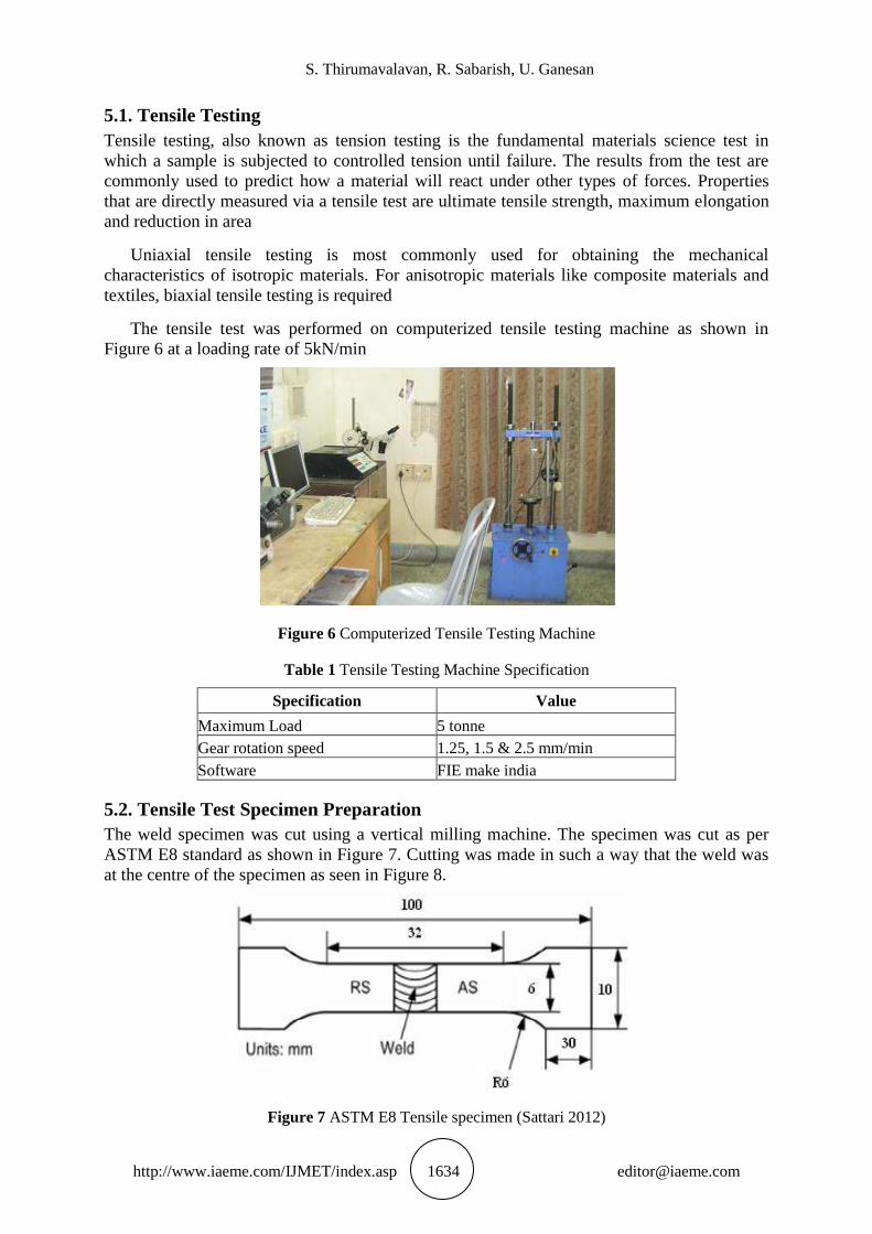
The tensile test was performed on computerized tensile testing machine as shown in
Figure 6 at a loading rate of 5kN/min
Figure 6 Computerized Tensile Testing Machine
Table 1 Tensile Testing Machine Specification
Specification Value
Maximum Load 5 tonne
Gear rotation speed 1.25, 1.5 & 2.5 mm/min
Software FIE make india
5.2. Tensile Test Specimen Preparation
The weld specimen was cut using a vertical milling machine. The specimen was cut as per
ASTM E8 standard as shown in Figure 7. Cutting was made in such a way that the weld was
at the centre of the specimen as seen in Figure 8.
Figure 7 ASTM E8 Tensile specimen (Sattari 2012)

Experimental Investigation on Friction Stir Welded Aluminium–Scilicon Alloy
http://www.iaeme.com/IJMET/index.asp 1635 [email protected]
Figure 8 Weld Specimen Cut to E8 Standard
The tensile specimen was held between the fixed and moving beam by grippers. The
initial gauge length was noted. The machine was switched ON. The curve was generated by
the software. When the weld breaks, the machine was switched OFF and the specimen was
removed. The final gauge length and final area of cross section was measured and fed into the
software.
5.3. Tensile Test Results
The tensile testing of the various welds provide information about the ultimate tensile
strength, fracture point, % of elongation, maximum elongation, reduction in area etc. Other
properties like 0.2% proof stress was measured from the curve, joint efficiency can be
calculated using the following formula.
The stress vs strain curves obtained from the software for all the four different welds are
given in the following Figures 9, 10, 11 and 12.
Figure 9 Stress vs Strain curve for Taper Cylindrical Threaded Pin Weld

S. Thirumavalavan, R. Sabarish, U. Ganesan
http://www.iaeme.com/IJMET/index.asp 1636 [email protected]
Figure 10 Stress vs Strain curve for Plain Cylindrical Threaded Pin Weld
Figure 11 Stress vs Strain curve for Taper Cylindrical Pin Weld
Figure 12 Stress vs Strain curve for Plain Cylindrical Pin Weld

Experimental Investigation on Friction Stir Welded Aluminium–Scilicon Alloy
http://www.iaeme.com/IJMET/index.asp 1637 [email protected]
Table 2 Comparison of Tensile Test Results
Properties
Ultimate
Tensile
Strength
(kN/mm2)
0.2% Proof
Stress (kN/mm2) % of Elongation
Reduction in
Area (%)
Joint Efficiency
(%)
Taper cylinder
threaded 0.182 0.138 14.867 35.964 58.71
Plain cylinder
threaded 0.183 0.132 3.5 9.222 59.03
Taper threaded 0.167 0.127 6.667 32.645 53.87
Plain threaded 0.134 0.083 1.033 6.761 43.23
From Table 10.2, it is seen clearly that threaded pins have dominant tensile properties than
the unthreaded pins. Between the two threaded pin profiles, the taper cylindrical threaded pin
profile has higher elongation characteristics than the plain cylindrical threaded pin profile. In
case of UTS and joint efficiency, the variation between the two threaded profiles was not
much high. So, it could be concluded that the weld made of taper cylindrical threaded pin
profile has dominant tensile characteristics among the four pin profiles.
5.4. Micro-Vicker’s Hardness Testing
Micro-Vickers hardness test is used to determine the hardness of the material to deformation.
When testing metals, indentation hardness correlates linearly with tensile strength. Figure 13
is the Micro Vickers hardness tester used.
Figure 13 Micro Vickers Hardness Tester
Table 3 Micro Hardness Testing Machine Specification
Specification Value
Load Range 10 gm to 1 kg
Magnification 100x and 1500x
Make & Model Baieiss – V test
In Micro-Vickers hardness test, a diamond indenter of specific geometry was impressed
into the surface of the test specimen using 3 kN loads. It has forces of 2N and produce
indentations of about 50 m. The specifications of Vickers tester is given in table 14. It has
been found that microhardness of almost any material was higher than its macrohardness.

S. Thirumavalavan, R. Sabarish, U. Ganesan
http://www.iaeme.com/IJMET/index.asp 1638 [email protected]
Micro-Vickers hardness test dis not require any special specimen preparation. The
specimen that was used for micro examination was used for finding hardness. The specimen
was placed on the table. The microscope was adjusted to get a clear image of the surface. The
table was moved towards the indenter. Now the indenter controller was switched ON. The
load of 300 gms was applied using the diamond tip indenter for a time of 10 secs. The
indenter automatically made an impression and returns back to its home position. The table
was moved towards the microscope. The focusing on the surface was done if required. In the
software, all the four corners of the indentation were marked. The software automatically
calculated the hardness value.
Figure 14 Micro-Hardness Curve for AA 6082 Welds
Table 4 Average Hardness at the Weld Nugget
Pin Profile Hardness Number (VHN) Distribution
Taper Cylindrical
Thread 68.71
Non-Uniform (max. at the RS and
decreases towards the AS)
Plain Cylindrical
Thread 75.03
Almost uniform (high at the interface and
low at weld centre)
Taper Cylinder 68.43
Non-Uniform (max. at the RS and
decreases towards the AS)
Plain Cylinder 50.87 Uniform (lowest at the weld centre)
It can be seen from the hardness curve in Figure 14 and Table 4, plain cylindrical threaded
pin weld has highest hardness of them all. So, it could concluded that plain cylindrical
threaded pin profile has high microhardness characteristics[19-20].
6. RESULTS & DISCUSSIONS
The microstructural analysis and mechanical testing on the friction stir welded joints were
performed and their results were obtained. By carefully interpreting these results, the
microstructural and mechanical characteristics of the four different welds could be briefly
described.
In case of the material flow around the pin, the threaded pins have given better material
mixing than the unthreaded pin profiles. This is because of the fact that the threads in the pin
transported the material from bottom to the top. In Taper cylindrical threaded pin profile, the
material near the threads gets caught by the rotating threads and moved the material upwards.

Experimental Investigation on Friction Stir Welded Aluminium–Scilicon Alloy
http://www.iaeme.com/IJMET/index.asp 1639 [email protected]
On moving up, the material undergoes a pressure rise because of the tapered profile. The
tapered pin occupies most area at the top region than at the bottom. The material then comes
out to the surface because of pressure. That material was again pushed back into the weld
zone by the shoulder. The material then moves downwards due to the shoulder effect. The
material flow in Plain cylindrical threaded pin profile was almost same to that of taper
cylindrical threaded pin with only exception that the pressure throughout the flow was
uniform and high.
In taper cylindrical pin profile, the material movement in vertical direction was restricted
because the surface was devoid of threads. The rotating pin imparted centrifugal force to the
material that comes in immediate contact with it. The material moved only around the tool in
its horizontal plane with no movement in vertical. In plain cylindrical pin profile, the pressure
was high throughout the thickness direction and flow was similar to taper cylindrical pin
profile.
Table 5 Grain Size Comparison
Pin Profile Taper cylindrical
thread
plain cylindrical
thread
Taper thread plain thread
Grain size (mm) 3 – 4 4 – 5 4 – 5 6 – 7
Table 5 indicates the grain size obtained in the weld nugget of the four different welds
made. From the table, it is clear that the taper cylindrical threaded pin results in finer
refinement of the grains. The taper cylindrical threaded pin refined the grains of 25 – 30 m
size in the base material to 3 – 4 m size at the weld nugget. The fine refinement of grains in
the weld nugget indicates that taper cylindrical threaded pin has given better weld than the
rest of the profiles.
Table 6 Percentage of Elongation Comparison
Pin Profile Taper cylindrical
thread
plain cylindrical
thread
Taper thread plain thread
% of Elongation 14.867 3.5 6.667 1.033
Table 6 indicates the % of elongation obtained through tensile testing of the four different
welds. From the table, it is clear that the weld made of taper cylindrical threaded pin profile
has high ductility and fails after an elongation of 14.867%. Only taper cylindrical threaded pin
has given such elongation. The remaining welds had not given atleast half the elongation. So,
the tensile properties of the weld made of taper cylindrical threaded pin were better than the
rest of welds
Table 7 indicates the micro-hardness obtained through Micro-Vickers hardness testing
Pin Profile Taper cylindrical
thread
plain cylindrical
thread
Taper thread plain thread
Hardness No (VHN) 68.71 75.03 68.43 50.87
Table 7 indicates the micro-hardness obtained through Micro-Vickers hardness testing of
the welds. The micro-hardness value of the weld made of plain cylindrical threaded pin
profile was the highest among the welds made. The plain cylindrical threaded pin has
hardness value of 75.03 VHN. But its % of elongation was only 3.5%. So, it could be said that
the weld made of plain cylindrical threaded pin was more brittle and couldn’t be said as better
weld. On moving to the next highest hardness value, weld made of taper cylindrical threaded

S. Thirumavalavan, R. Sabarish, U. Ganesan
http://www.iaeme.com/IJMET/index.asp 1640 [email protected]
pin has hardness value of 68.71 VHN and 14.867% of elongation. This clearly indicates that it
has undergone a ductile fracture. So, the weld made of taper cylindrical threaded pin profile
exhibit high mechanical properties than the rest of welds.
It could be summarized that the weld made of taper cylindrical threaded pin has high
mechanical properties and finer grain refinement in weld nugget. The weld made of taper
cylindrical threaded pin is the optimal weld among the four welds made.
7. CONCLUSIONS
In the present research work, effects of tool pin profile on microstructure and mechanical
properties of Friction stir welded Al - Si joints were investigated using four different tool pin
profiles, i.e., taper cylindrical threaded, plain cylindrical threaded, taper cylindrical and plain
cylindrical pin profiles. Based on the results obtained in this work, the following conclusions
could be drawn:
Sample welded using taper cylindrical threaded pin profile showed fine recrystallized grains
of about 3 m. The grains were evenly distributed throughout the weld nugget region.
The mechanical properties of the joints were in relationship with the grain size and therefore,
sample welded using taper cylindrical threaded pin profile showed higher mechanical
properties relative to sample welded using other pin profiles. It has the elongation of 14.867%
which was highest among the welds made.
The axisymmetric flow of material around the tool pin and also along the vertical direction
was a prime reason for such grain refinement and increased mechanical properties in weld
made of taper cylindrical threaded tool pin profile.
REFERENCES
[1] Akos Meilinger & Imre Torok 2013, “The Importance of Friction Stir Welding Tool”,
Production Processes and Systems, vol. 6, no. 1, pp. 590 – 596.
[2] L.Escalin Tresa & Dr.M.Sundhararajan,” An Intelligent repeated objects tracking on
Video Sequences”, Published in International Journal of Applied Engineering Research,
Vol. 10 No.5(2015).pp 11803-11810.
[3] Ehab A. El-Danaf & Magdy M. El-Rayes 2013, “Microstructure and Mechanical
Properties of Friction Stir Welded AA6082 in As Welded and Post Weld Heat Treated
Conditions”, Materials and Design, vol. 46, pp. 561 – 572.
[4] Gopalakrishnan, K., Prem Jeya Kumar, M., Sundeep Aanand, J., Udayakumar, R.,
Thermal properties of doped azopolyester and its application, Indian Journal of Science
and Technology, v-6, i-SUPPL.6, pp-4722-4725, 2013.
[5] Harinder Grover, Himanshu Tripathi & Raman Sharma 2011, “Experimental Study of
FSW Process Parameters on Tensile Strength of the Al-Si Alloy”, International Journal of
Advanced Engineering Technology, vol. 2, no. 3, pp. 164 – 170.
[6] Revati Shriram & Dr.M.Sundhararajan,” Coherence Analysis of Pressure Pulse and
Photoplethysmogram at Various sites”, Published in International Journal of Applied
Engineering Research, Vol. 10 No.6(2015).pp 14959-14968.
[7] Krasnowski, K, Hamilton, C & Dymek, S 2014, “Influence of Tool Shape and Weld
Configuration on Microstructure and Mechanical Properties of Al 6082 Alloy FSW
Joints”, Archives of Civil and Mechanical Engineering, vol. 6, pp. 193 – 202.
[8] Sharmila, S., Jeyanthi Rebecca, L., Das, M.P., Saduzzaman, M., Isolation and partial
purification of protease from plant leaves, Journal of Chemical and Pharmaceutical
Research, v-4, i-8, pp-3808-3812, 2012.

Experimental Investigation on Friction Stir Welded Aluminium–Scilicon Alloy
http://www.iaeme.com/IJMET/index.asp 1641 [email protected]
[9] Khodaverdizadeh, H, Heidarzadeh, A & Saeid, T 2013, “Effect of Tool Pin Profile on
Microstructure and Mechanical Properties of Friction Stir Welded Pure Copper Joints”,
Materials and Design, vol. 45, pp. 265 – 270.
[10] Nivedita Daimiwal, Dr.M.Sundhararajan & Revati Shriram,” NIRS Based PPG Sensor For
Detection of Oxy –Hb and Deoxy-Hb Change During Activity”, Published in International
Journal of Applied Engineering Research, Vol. 10 No.7(2015).pp 17347-17356.
[11] Leitao, C, Leal, RM, Rodrigues, DM, Vilaca, P & Loureiro, A 2008, “Material Flow in
Friction Stir Welding”, Microsc Microanal, vol. 14, no. 3, pp. 87 – 90.
[12] Sengottuvel, P., Satishkumar, S., Dinakaran, D., Optimization of multiple characteristics
of EDM parameters based on desirability approach and fuzzy modeling, Procedia
Engineering, v-64, i-, pp-1069-1078, 2013.
[13] Motalleb-nejad, P, Saeid, T, Heidarzadeh, A, Darzi, KH & Ashjari, M 2014, “Effect of
Tool Pin Profile on Microstructural and Mechanical Properties of Friction Stir Welded
AZ31B Magnesium Alloy”, Materials and Design, vol. 59, pp. 221 – 226.
[14] S.Arul Selvi & M.Sundararajan,” A Combined Framework for Routing and Channel
Allocation for Dynamic Spectrum Sharing using Cognitive Radio”, Published in
International Journal of Applied Engineering Research, Vol. 11 No.7(2015).pp 4951--
4953.
[15] Narges Dialami, Michele Chiumenti, & Miguel Cervera 2005. “Material Flow
Visualization in Friction Stir Welding via Particle Tracing”, Journal of Materials Science,
vol. 31, pp. 55 - 63.
[16] Anbazhagan, R., Satheesh, B., Gopalakrishnan, K., Mathematical modeling and
simulation of modern cars in the role of stability analysis, Indian Journal of Science and
Technology, v-6, i-SUPPL5, pp-4633-4641, 2013.
[17] Padmanaban, G & Balasubramanian, V 2009, “Selection of FSW Tool Pin Profile,
Shoulder Diameter and Material for Joining AZ31B Magnesium Alloy – An Experimental
Approach”, Materials and Design, vol. 30, pp. 2647 – 2656.
[18] Raghu Babu, G, Murti, KGK & Ranga Janardhana, G 2008, “Experimental Study on
Effect of Welding Parameters on Mechanical and Microstructural Properties of AA 6082 -
T6 Friction Stir Welded Butt Joints”, ARPN Journal of Engineering and Applied
Sciences, vol. 3, no. 5, pp. 68 – 74.
[19] Ram Niwas Bishnoi, Pawan Kumar Sapra & Raman Bhambhu 2013, “Effect of Tool Pin
Profile on Mechanical Properties of Single and Double Sided Friction Stir Welded
Aluminium Alloy AA19000”, International Journal of Current Engineering and
Technology, vol. 3, no. 4, pp. 1338 – 1341.
[20] Surya Prakash, B Prashanth, GVR Seshagirirao and J Anoop. Experimental Investigations
of TIG and Friction Stir Welding Process for AA7075. International Journal of
Mechanical Engineering and Technology, 8(7), 2017, pp. 290-297
Related Documents