Control Engineering Practice 16 (2008) 333–346 Experimental controller tuning and QoS optimization of a wireless transmission scheme for real-time remote control applications $ George Nikolakopoulos , Athanasia Panousopoulou, Anthony Tzes Electrical and Computer Engineering Department, University of Patras, Rio 26500, Greece Received 16 January 2007; accepted 30 April 2007 Available online 26 June 2007 Abstract In this paper an experimental optimization of a wireless (802.11b) transmission scheme, coupled to the tuning process of the controller parameters, for real-time control applications is presented. In congested wireless networked controlled systems (WNCS), there is considerable loss of data-packets in the transmission process between the client and server sides. Accordingly the quality of service (QoS) suffers and the system’s performance deteriorates. An integrated framework is proposed, which monitors the QoS-factor, and (a) adjusts the data retransmission attempts, and (b) periodically tunes the controller’s parameters. Experimental studies on a WNCS-prototype are used for the optimization procedure. These studies indicate the need for a compromise between the achieved QoS, the network’s throughput, and the selected sampling period. r 2007 Elsevier Ltd. All rights reserved. Keywords: Networked controlled systems; 802.11b protocol; QoS; Gain scheduling 1. Introduction Remote client–server architectures are becoming domi- nant due to the developments in the communication capabilities and the improvements in the networks infra- structures. These networks are susceptible to various issues (Chrysostomou, Pitsillides, Rossides, Polycarpou, & Sekercioglu, 2003; Overstreet & Tzes, 1999; Tzes, Nikola- kopoulos, & Koutroulis, 2005) stemming from the need to exchange information over a communication link (Good- win, Haimovich, Quevendo, & Welsh, 2004; Halevi & Ray, 1988; Hussain & Marshall, 2003; Kim, Shin, & Kwon, 2004; Ray & Halevi, 1988; Recht & Andrea, 2004). The utilization of a common wireless communication network (Crow, Widjaja, Kim, & Sakai, 1997; IEEE Std 802.11, 2001; Moller, Johansson, & Hjalmarsson, 2004; Priscoli & Isidori, 2005; Sweet & Sidhu, 1999), where the end user has no control over the provided communication link, leads to an expression of problems associated with the data packet interchange. The resulting WNCS should be able to adjust the settings of their transmission scheme to account for the possible peculiarities encountered in typical real-time control application problems. The most common problems that can be encountered are related to the need for: (a) maintaining an effective bit-rate (Nair, Evans, Mareels, & Moran, 2003), (b) synchronizing heterogeneous computers with varying computing power, (c) utilizing a large bandwidth for the sampling applications (Wong & Brockett, 1999), (d) accounting for loss-of-packets in classical wireless transmissions, (e) using the unreliable UDP rather than the TCP protocol for control related purposes (Overstreet & Tzes, 1999), and (f) stabilizing the resulting time-delayed system (TDS) (Walsh, Ye, & Bushnell, 2002). In the WNCS area, due to the limited bandwidth, there is a need to design controllers with a definite bit-rate ARTICLE IN PRESS www.elsevier.com/locate/conengprac 0967-0661/$ - see front matter r 2007 Elsevier Ltd. All rights reserved. doi:10.1016/j.conengprac.2007.04.015 $ This work was partially supported by (a) the Greek Ministry’s of Education Herakleitos Research Program, (b) the HYCON Network of Excellence (contract number FP6-IST-511368), (c) EU’s FP6 Technolo- gies-004536 RUNES research program, and (d) the European Social Fund (75%), the Greek Secretariat Research and Technology (25%) and ATMEL HELLAS S.A., within the framework of Measure 8.3 of the Operational Programme ‘‘Competitiveness’’ and the 3rd Community Support Programme (PENED03868). Corresponding author. E-mail address: [email protected] (G. Nikolakopoulos).

Welcome message from author
This document is posted to help you gain knowledge. Please leave a comment to let me know what you think about it! Share it to your friends and learn new things together.
Transcript
ARTICLE IN PRESS
0967-0661/$ - se
doi:10.1016/j.co
$This work
Education Hera
Excellence (con
gies-004536 RU
(75%), the Gr
ATMEL HELL
Operational Pr
Support Progra�CorrespondE-mail addr
Control Engineering Practice 16 (2008) 333–346
www.elsevier.com/locate/conengprac
Experimental controller tuning and QoS optimization of a wirelesstransmission scheme for real-time remote control applications$
George Nikolakopoulos�, Athanasia Panousopoulou, Anthony Tzes
Electrical and Computer Engineering Department, University of Patras, Rio 26500, Greece
Received 16 January 2007; accepted 30 April 2007
Available online 26 June 2007
Abstract
In this paper an experimental optimization of a wireless (802.11b) transmission scheme, coupled to the tuning process of the controller
parameters, for real-time control applications is presented. In congested wireless networked controlled systems (WNCS), there is
considerable loss of data-packets in the transmission process between the client and server sides. Accordingly the quality of service (QoS)
suffers and the system’s performance deteriorates. An integrated framework is proposed, which monitors the QoS-factor, and (a) adjusts
the data retransmission attempts, and (b) periodically tunes the controller’s parameters. Experimental studies on a WNCS-prototype are
used for the optimization procedure. These studies indicate the need for a compromise between the achieved QoS, the network’s
throughput, and the selected sampling period.
r 2007 Elsevier Ltd. All rights reserved.
Keywords: Networked controlled systems; 802.11b protocol; QoS; Gain scheduling
1. Introduction
Remote client–server architectures are becoming domi-nant due to the developments in the communicationcapabilities and the improvements in the networks infra-structures. These networks are susceptible to various issues(Chrysostomou, Pitsillides, Rossides, Polycarpou, &Sekercioglu, 2003; Overstreet & Tzes, 1999; Tzes, Nikola-kopoulos, & Koutroulis, 2005) stemming from the need toexchange information over a communication link (Good-win, Haimovich, Quevendo, & Welsh, 2004; Halevi & Ray,1988; Hussain & Marshall, 2003; Kim, Shin, & Kwon,2004; Ray & Halevi, 1988; Recht & Andrea, 2004).
e front matter r 2007 Elsevier Ltd. All rights reserved.
nengprac.2007.04.015
was partially supported by (a) the Greek Ministry’s of
kleitos Research Program, (b) the HYCON Network of
tract number FP6-IST-511368), (c) EU’s FP6 Technolo-
NES research program, and (d) the European Social Fund
eek Secretariat Research and Technology (25%) and
AS S.A., within the framework of Measure 8.3 of the
ogramme ‘‘Competitiveness’’ and the 3rd Community
mme (PENED03868).
ing author.
ess: [email protected] (G. Nikolakopoulos).
The utilization of a common wireless communicationnetwork (Crow, Widjaja, Kim, & Sakai, 1997; IEEE Std802.11, 2001; Moller, Johansson, & Hjalmarsson, 2004;Priscoli & Isidori, 2005; Sweet & Sidhu, 1999), where theend user has no control over the provided communicationlink, leads to an expression of problems associated with thedata packet interchange. The resulting WNCS should beable to adjust the settings of their transmission scheme toaccount for the possible peculiarities encountered in typicalreal-time control application problems. The most commonproblems that can be encountered are related to the needfor: (a) maintaining an effective bit-rate (Nair, Evans,Mareels, & Moran, 2003), (b) synchronizing heterogeneouscomputers with varying computing power, (c) utilizing alarge bandwidth for the sampling applications (Wong &Brockett, 1999), (d) accounting for loss-of-packets inclassical wireless transmissions, (e) using the unreliableUDP rather than the TCP protocol for control relatedpurposes (Overstreet & Tzes, 1999), and (f) stabilizingthe resulting time-delayed system (TDS) (Walsh, Ye, &Bushnell, 2002).In the WNCS area, due to the limited bandwidth, there
is a need to design controllers with a definite bit-rate

ARTICLE IN PRESSG. Nikolakopoulos et al. / Control Engineering Practice 16 (2008) 333–346334
(Li & Baillieul, 2004; Nair & Evans, 2000, 2003; Nair et al.,2003) or to reduce the number of data packet exchangesbetween the sensor and the actuator by utilizing aplant model in the side of the actuator to provide anestimation of the system whenever the sensor data arenot adequate (Montestruque & Antsaklis, 2003), in orderto maintain certain stability margins. In these casesthere is an obvious conflict between the need to achievehighest bit-rate transmissions and reduce the percentageof the data-packet losses, while ensuring the systemstability.
In NCS the selection of the sampling rate is ofparamount importance not only for ensuring the stabilityof the controlled system, but also for avoiding thebottleneck of the network (Nair, Fagnani, Zampieri, &Evans, 2007). The relationship between network’s perfor-mance and sampling rate was studied in Lian (2001); Lian,Moyne, and Tilbury (2002). More specifically, fastsampling leads to increased data transmission rate andthus to increased requirements in terms of bandwidthavailability. For a non-control-dedicated network, such asa common data network is, this may result in phenomenasuch as bottleneck, repeated retransmissions, communica-tion delays and in general data losses. Successive datalosses constrain the amount of information required for theplant’s control and consequently may drive the TDS toinstability. On the other hand, slow sampling does notaffect the network’s performance due to low datatransmission rate, but deteriorates the system’s perfor-mance, since there exist no adequate control information todrive the plant to the desired behavior. Consequently, thesampling rate should be fast enough to ensure plant’sstability and slow enough to prevent from undesirablenetwork behavior.
The research presented aims at highlighting, on anexperimental basis, the close interaction between thecontroller’s and the network’s attributes of a IEEE802.11b–WNCS. More precisely, a Quality-of-Service(QoS) module is inserted into the control loop. This QoS-module measures the network packet losses occurred, inorder to periodically characterize the performance of theunderlying network. When the network’s performance ispoor, the QoS-module attempts to improve the qualityof the data delivery through the wireless medium by dataretransmissions. The controller’s parameters, whichare also affected by the QoS-module, are periodicallyupdated, while preserving the system from destabilization.Classical analysis tools (Linear Matrix Inequalities) areoffered to bridge the ‘‘interaction gap’’ among the QoS-module (Van Antwerp & Braatz, 2000) and the controller’sdesign.
This paper’s structure is the following. In Section 2 theproblem statement for the WNCS is provided, while inSection 3 the main features of the communicationprotocols (802.11b and UDP) are presented. Experimentalresults are presented in Section 4, and conclusive remarksare drawn in Section 5.
2. Problem statement
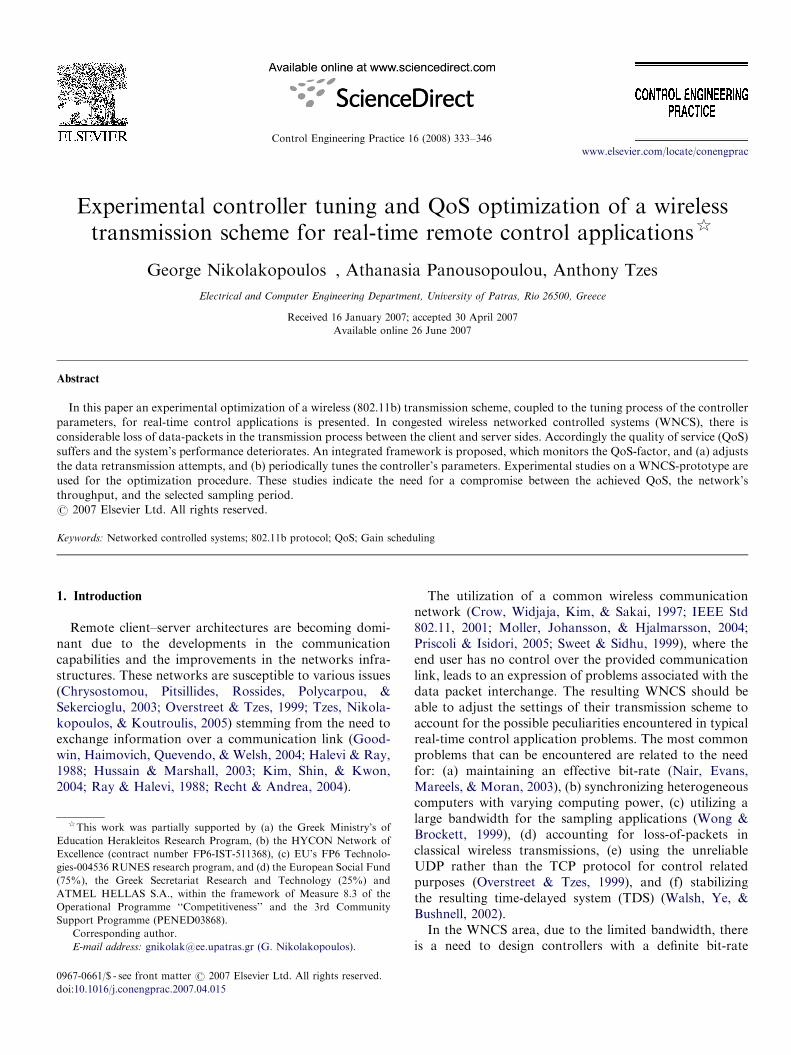
In a WNCS shown in Fig. 1, the system output yðtÞ
(control command uðtÞ) is transmitted in a wireless mannerto the controller (plant). Assume the plant’s transferfunction representation in the state space:
_xðtÞ ¼ AxðtÞ þ BuðtÞ,
yðtÞ ¼ CxðtÞ. ð1Þ
Based on the classical zero-order-hold (ZOH) transforma-tion, the discrete time state space description of the systemin Eq. (1), with sampling period Ts is
xðk þ 1Þ ¼ AxðkÞ þ BuðkÞ,
yðkÞ ¼ CxðkÞ, ð2Þ
where xðkÞ�Rn and uðkÞ�Rm.
2.1. Mathematical formulation of NCS
Let a primitive controller structure of the form (staticoutput feedback) ~uðkÞ ¼ KeðkÞ ¼ KðrðkÞ � yðkÞÞ. The nat-ure of the wireless transmission (collision hits, retransmis-sions, packet losses) results in transmission delays. Theclient-to-server transmission delay, as shown in Fig. 1,uðkÞ ¼ ~uðk � d1Þ and the reverse eðkÞ ¼ rðkÞ � yðk � d2Þ
results in a TDS. Let rðkÞ ¼ 0 and dðkÞ ¼ d1 þ d2 be theoverall delay at time instance k.If the overall delay is time varying, the resulting control
law is given by
uðkÞ ¼ KdðkÞCxðk � dðkÞÞ,
where dðkÞ is a random bounded sequence of integersdðkÞ 2 ½0; 1; . . . ;D�, D is the upper bound of the delay termand KdðkÞ is the controller’s gain, where the index d is usedto emphasize its dependency on the delay. The closed-loopsystem is formed by augmenting the state vector to ~xðkÞ, inorder to include all the delayed terms, as
~x ¼ ½xðkÞT; xðk � 1ÞT . . . xðk �DÞT�T.
The dynamics of the open-loop system, at time k, with theaugmented state vector take the following form:
~xðk þ 1Þ ¼ ~A ~xðkÞ þ ~BuðkÞ,
yðkÞ ¼ ~CdðkÞ ~xðkÞ,
where xðkÞ�RðDþ1Þ�n, and
~A ¼
A 0 . . . 0
I 0 . . . 0 0
0 I . . . 0 0
..
. ... ..
. ... ..
.
0 0 . . . I 0
2666666664
3777777775; ~B ¼
B
0
0
..
.
0
2666666664
3777777775,
~CdðkÞ ¼ ½0̄ . . . 0̄ C 0̄ . . . 0̄�, ð3Þ
where the vector 0̄�R1�n has all its elements zeroed, and thevector C appear at the dðkÞth block of the vector ~Cd .
ARTICLE IN PRESS
Wireless LAN
DeviceWirelessLAN
Device
Feedback
Control
Signal
QoS
Controller
y(k)
u(k)~
y(k-d2)
Latency Time
K
+r(k)
QoS-Module
Scheduling
Controller
d1
d2
u(k)=u(k-d1)
x(s)=Ax(s)+Bu(s)
y(s)=Cx(s)
.
~
ZOHTs
Gain
Fig. 1. WNCS structural representation.
G. Nikolakopoulos et al. / Control Engineering Practice 16 (2008) 333–346 335
Moreover, the augmented state vector affects also thecontrol structure, which obtains the following form:
~KdðkÞ ¼ ½0 . . . 0 KdðkÞ 0 . . . 0�. (4)
The closed loop system is switched, since dðkÞ (and thus thefeedback term ~Kd ðkÞ ~Cd ðkÞ) is of time-varying nature. Theoverall closed loop system is
~xðk þ 1Þ ¼ ð ~Aþ ~B ~KdðkÞ ~CdðkÞÞ ~xðkÞ, ð5Þ
yðkÞ ¼ ~CdðkÞ ~xðkÞ. ð6Þ
The closed loop matrix ~Aþ ~B ~KdðkÞ ~CdðkÞ can switch inany of the Dþ 1-vertices Ai ¼ ~Aþ ~B ~Ki
~Ci, and thereforeconditions are sought for the stabilization of the switchedsystem:
~xðk þ 1Þ ¼ Ai ~xðkÞ; i ¼ 0; . . . ;D.
Under the assumption that at every time instance k thelatency time dðkÞ ¼ d1ðkÞ þ d2ðkÞ can be measured, andtherefore, the index of the switched-state is known, thesystem can be described as
xðk þ 1Þ ¼XD
i¼0
xiðkÞAixðkÞ, (7)
where
xðkÞ ¼ ½x0ðkÞ; . . . ; xDðkÞ�T and x ¼
1 mode ¼ Ai;
0 modeaAi:
(
The stability of the switched system in (7) is ensured ifDþ 1 positive definite matrices Pi; i ¼ 0; . . . ;D can befound that satisfy the following LMI:
Pi ATi Pj
PjAi Pj
24
3540; 8ði; jÞ 2 I � I ,
Pi40; 8i 2 I ¼ f0; 1; . . . ;Dg. ð8Þ
It should be noted that if a time-invariant controller issought ð ~Ki ¼ K ;8iÞ, the controller selection processamounts to the computation of the largest setsI ¼ fImin; Imin þ 1; . . . ; Imaxg, where 0pIminoImaxpD for
which the preset controller gain can stabilize the systemagainst any switching within members of this set. Bynature this philosophy results in a conservative controllerdesign, and less conservative approaches (Hetel, Daafouz,& Iung, 2006) using switched discrete have recentlyemerged.
2.2. WNCS attributes
In WNCS, the communication delays (latency times)cause significant deterioration in the system’s performance.Other factors like the reordering and loss of data packets aswell as the attainable communication bit-rate impede thecontroller design process (Tipsuwan & Chow, 2003).The last factors are of paramount importance in
congested networks, typical in a clustered WNCS, wherethe transmitter cannot easily find a free time-slot totransmit its data packet. In this case, the transmitterdetects a collision and re-attempts for its transmission.In general data retransmission is built inherently in the
MAC-layer to handle the collisions (Cali, Conti, &Gregori, 1998; Crow et al., 1997) of the control messages.These retransmissions subtract channel bandwidth fromthe available one for the successful message transmission.Over the past years, several attempts have focused on theretransmission issue either at the MAC-layer (Wu, Peng,Long, Cheng, & Nat, 2002) relying on enhancements basedon the hidden Markov-sequence of the retransmissionframework, or at the transport layer (Moller et al., 2004;Hwang & Cho, 2004; Fotiadis & Siris, 2005) where there issignificant promise that a modification of the retransmis-sion mechanism can result in a higher throughput. In thiscase, the attempt made is focused on affecting the QoS onthe application layer (Panousopoulou, Nikolakopoulos,Tzes, & Lygeros, 2006) rather than on the lower layers(transport and MAC). It should be noted that the typicalused approach (Hespanha, Naghshtabrizi, & Xu, 2007)(in the application layer) is to avoid packet retransmissionand attempt to design conservative controllers that canprovide robustness against packet dropouts.

ARTICLE IN PRESS
Physical Layer
FH, DS, IR
Logical Link Control(LLC) - 802.2
Media Access Control(MAC)
DataLink Layer
Physical Layer
Upper Layer Protocols of OSI
Network Layer
UDP,TCPTransport Layer
802.1
1b
IP
Fig. 2. Lower-four OSI communication layers (802.11b, UDP/IP proto-
cols).
G. Nikolakopoulos et al. / Control Engineering Practice 16 (2008) 333–346336
Packet transmission increases the communicationload and the overhead associated with it. To avoid thecontinuous attempts for packet retransmissions usingthe UDP-protocol via a wireless link, after a certaintime the transmitter quits, and flags that attempt as afailed one (loss-of-packet). However, a large number(percentage) of packet losses can significantly affect theperformance of the system and reduce the stabilitymargins.
The need to retransmit the data packet results in a pureincrease of the overall delay dðkÞ at the kth instant. From acontrol point of view, the dðkÞ-latency time needs to be assmall as possible; at the same time this increases the load(bit-rate) on the communication network due to the fasttransmissions of the control commands.
A compromise is sought to balance the bit-rate on thewireless link and the need to reduce the latency time forcontrol purposes. Low bit-rates will result in large latencytimes and the system can be destabilized. Small latencytimes may cause bottleneck on the queues of thetransceivers and the link may collapse for short periodsof time.
In this paper, in a prototype WNCS a QoS-module isinserted in each unidirectional communication link toaccount for the loss-of-packets as shown in Fig. 1. Thismodule monitors the recorded lost packets over a slidingwindow, and assigns a certain time interval prior to thenext retransmission. This pre-timed delayed retransmissionresults in a reduced communication load (traffic) at theexpense of applying the control signal to the plant with alarge delay.
To account for these artificially induced delays (by theQoS-module), rather than maintaining a fixed (time–invariant) controller an ad hoc tuning scheme for thecontroller parameters is proposed in order to maintaina certain degree of stability. In this manner, when thelatency time is small the controller gains are indirectlyadjusted so as to increase the closed-loop system band-width. Furthermore, to avoid a continuous tuningof the controller parameters and an increase on theoverhead this process takes place at certain time intervals(batch-tuning).
Strictly, from an experimental point of view, the resultspresented in the sequel indicate the need for the develop-ment and deployment of such a QoS-module and asimplified controller tuning scheme in congested WNCS.An ad hoc procedure for tuning the parameters of such amodule is examined in the sequel by: (1) observing theintricacies of the communication protocols (802.11b anduser Datagram Protocol (UDP)), and (2) obtainingstatistical data regarding the behavior of the wirelesstransmission scheme in lieu of certain parameters (signalstrength, distance between receiver and transmitter, line-of-sight variations, etc.). The batch-tuning procedure isexamined in the following sections and the experimentalresults indicate the need to couple this with the developedQoS-module.
3. Communication protocols
The protocols used in this study are: (a) the IEEE802.11b for the data link and physical layers, and (b) the IPand UDP for the network and transport layers, respec-tively, as shown in Fig. 2.
3.1. 802.11b protocol
The IEEE 802.11b standard (IEEE Std 802.11, 2001) is aprotocol for RF–communication. The standard covers thelower levels (physical layer and medium access control sub-layer) in the OSI model. By using high rate DSSS for datatransmission through the wireless network, 802.11b oper-ates at the 2.4GHz ISM band frequency, while it offersfour transmission data rates: 1, 2, 5.5 and 11Mbps. TheMAC layer utilizes the carrier sense multiple access withcollision avoidance (CSMAnCA) protocol for accessing thecommunication medium. Compared with the CSMA withcollision detection (CSMAnCD) protocol which is widelyused in local area networks, the CSMAnCA protocolprovides a better prediction method in accessing thetransmission medium. CSMAnCA’s main advantage isthe ability of predicting the network’s response time fordata packets transmission, although it cannot providecertain bounds for the delays in the transmission, neitherprevent the collisions of the data packets.The 802.11b (also known as Wi-Fi) is primarily a data
transmission protocol, having its QoS focused on thenetwork’s bandwidth and the utilization of high transmis-sion data-rate. The 802.11b is not considered a real-timecommunication protocol and the inserted communicationdelays can deteriorate the performance of a WNCS system.In a client–server topology, the use of the 802.11b
protocol for the system stabilization is challenging due tothe behavior of the wireless medium. The protocol’sperformance depends on the distance between the clientand server sides, the data rate and the signal strength.Referring to indoor environments, the transmitted signalwill be propagated through the medium by differentmechanisms (such as reflection and diffraction), will
ARTICLE IN PRESSG. Nikolakopoulos et al. / Control Engineering Practice 16 (2008) 333–346 337
experience path loss due to obstacles (e.g. walls, floors,ceilings) and will reach its destination via multiple paths.
3.2. UDP-protocol
Theoretically, transport layer protocols are independentfrom the underlying technology. However, this is oppositeto real-word implementations. For example, the perfor-mance of the transport control protocol (TCP) in wirednetwork is different from the one in the wireless network.This is a consequence of the congestion control algorithmthe latter utilizes; in cases of heavy-loaded networks, TCP’spolicy attempts to reduce the data transmission rate(Tanenbaum, 1996; Xylomenos & Polyzos, 2001). Inwireless networks, where the link is in general unreliable,data losses are confronted with retransmissions. Thus, thereduction of data transmission rate in the case of dataretransmission contributes to packet losses percentage.However, when the user datagram protocol (UDP) isutilized, no such issues arise; UDP is a connection-lessprotocol and therefore, acknowledgment signals are notrequired for synchronizing the client and server sides. Thechoice of UDP as the transport protocol introduces thesynchronization problem, since characteristics such asreliable connection, flow control and handshaking schemesare not supported. Moreover, the usage of UDP can lead todatagrams’ retroactivity, meaning that a packet trans-mitted at k-instant may reach its destination after thepacket transmitted at the ðk þ iÞ-instant. Despite thedrawbacks, UDP has reduced overhead since it neitheroffers packet re-ordering, nor asks for retransmission oflost packets and therefore is the proper choice for controlrelated purposes, as it provides a better real-time behaviorthan TCP does. Moreover, it was shown in Aad andCastelluccia (2003); Xylomenos and Polyzos (1999);Hundal, Makrakis, and Galladro (1999) that wirelessnetworks behave better under the UDP transport protocolrather than TCP in terms of throughput, since TCPprotocol introduces significant overhead during the com-munication process. Under these considerations UDP istypically preferred in remote control applications over TCP(Overstreet & Tzes, 1999), where real-time response iscrucial.
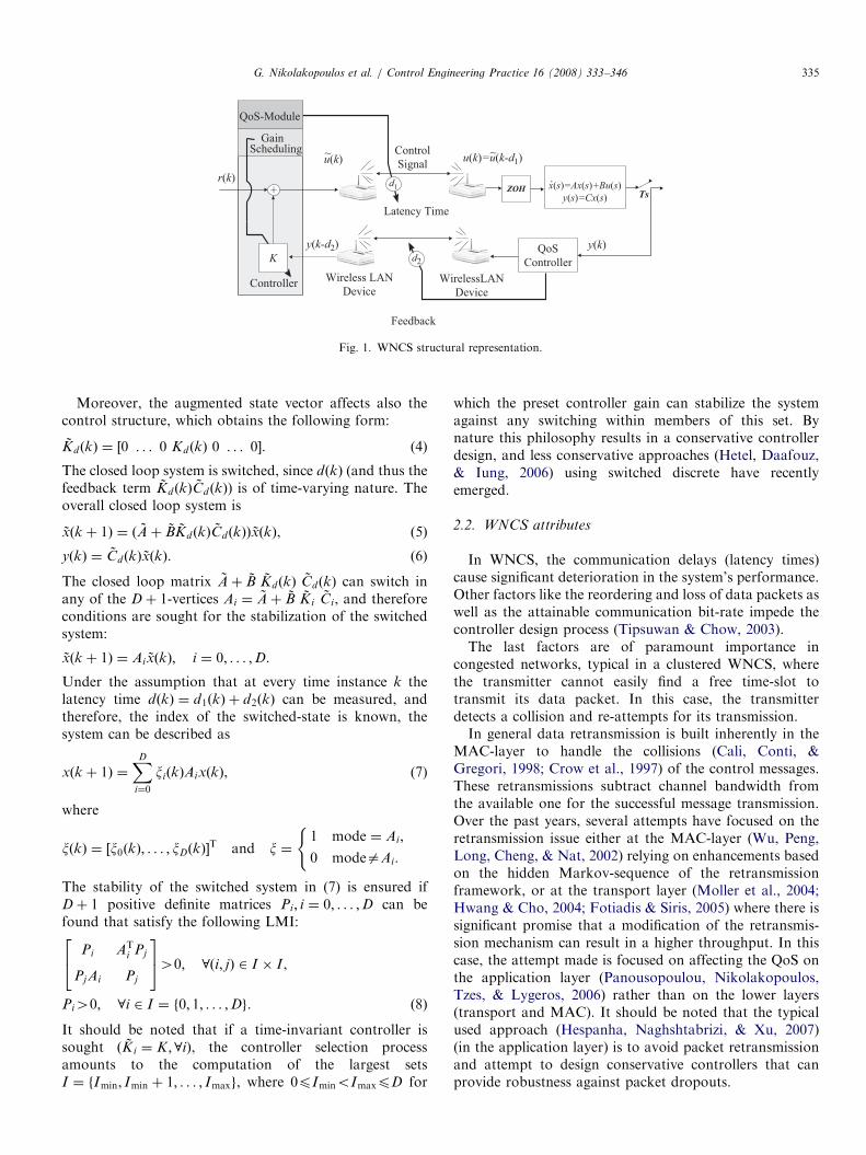
UDP packets are embedded in IP-datagrams. Since IP-packets have a maximum length of 576 bytes, the UDP-
Client
Wireless LAN
Device
F
ru
yt
Fig. 3. Client–server netwo
related information is 516 bytes (60 bytes IP-header) out ofwhich only 500 bytes are the useful data (16 bytes UDP-header).
3.3. Experimental Wi-Fi network behavior
Prior to the tuning of the QoS-module, a study isperformed on testing the attributes of the client–servercommunication link. Each side is equipped with a Wi-Fi(802.11b) WLAN Media Access Controller and operateson a ‘‘peer-to-peer’’ environment.Proper software has been developed for the monitoring
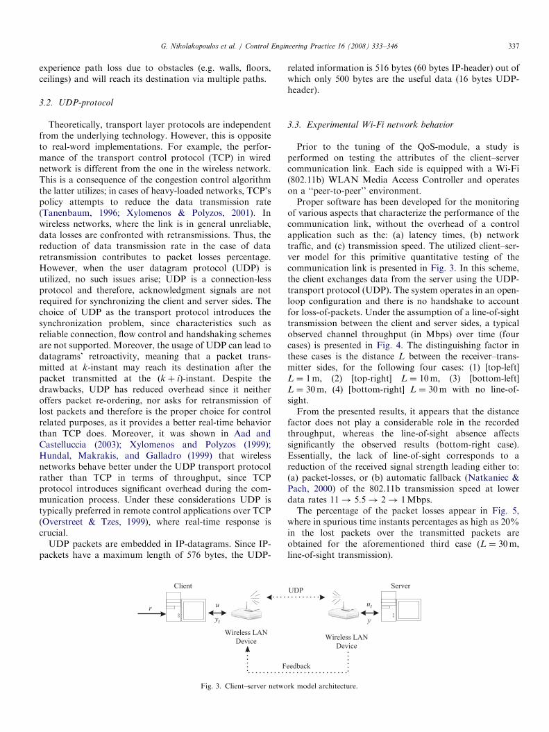
of various aspects that characterize the performance of thecommunication link, without the overhead of a controlapplication such as the: (a) latency times, (b) networktraffic, and (c) transmission speed. The utilized client–ser-ver model for this primitive quantitative testing of thecommunication link is presented in Fig. 3. In this scheme,the client exchanges data from the server using the UDP-transport protocol (UDP). The system operates in an open-loop configuration and there is no handshake to accountfor loss-of-packets. Under the assumption of a line-of-sighttransmission between the client and server sides, a typicalobserved channel throughput (in Mbps) over time (fourcases) is presented in Fig. 4. The distinguishing factor inthese cases is the distance L between the receiver–trans-mitter sides, for the following four cases: (1) [top-left]L ¼ 1m, (2) [top-right] L ¼ 10m, (3) [bottom-left]L ¼ 30m, (4) [bottom-right] L ¼ 30m with no line-of-sight.From the presented results, it appears that the distance
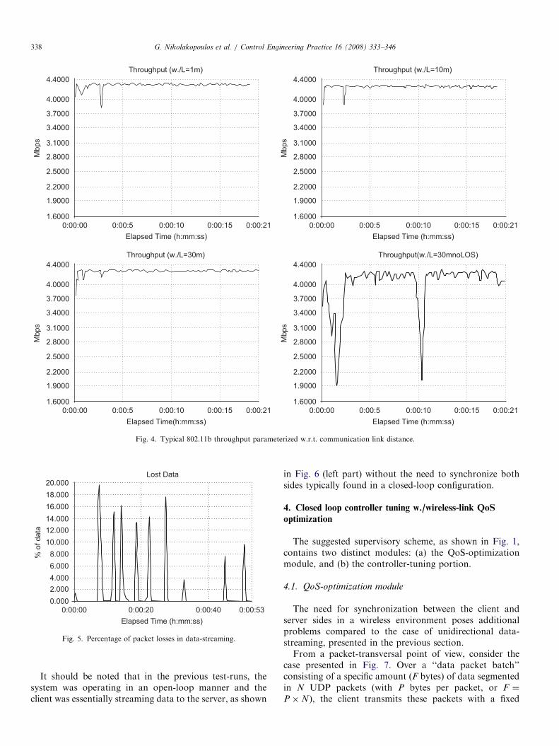
factor does not play a considerable role in the recordedthroughput, whereas the line-of-sight absence affectssignificantly the observed results (bottom-right case).Essentially, the lack of line-of-sight corresponds to areduction of the received signal strength leading either to:(a) packet-losses, or (b) automatic fallback (Natkaniec &Pach, 2000) of the 802.11b transmission speed at lowerdata rates 11! 5:5! 2! 1Mbps.The percentage of the packet losses appear in Fig. 5,
where in spurious time instants percentages as high as 20%in the lost packets over the transmitted packets areobtained for the aforementioned third case (L ¼ 30m,line-of-sight transmission).
ServerUDP
Wireless LAN
Device
eedback
ut
y
rk model architecture.
ARTICLE IN PRESS
0:00:00 0:00:5 0:00:10 0:00:15
Mbps
0:00:21
1.9000
2.2000
2.5000
2.8000
3.4000
4.0000
3.1000
1.6000
3.7000
4.4000
Throughput (w./L=1m)
Elapsed Time (h:mm:ss)
0:00:00 0:00:5 0:00:10 0:00:15
Elapsed Time (h:mm:ss)
Mbps
0:00:21
1.9000
2.2000
2.5000
2.8000
3.4000
4.0000
3.1000
1.6000
3.7000
4.4000
Throughput(w./L=30mnoLOS)
Elapsed Time(h:mm:ss)
Throughput (w./L=30m)
0:00:00 0:00:5 0:00:10 0:00:15
Mbps
0:00:21
1.9000
2.2000
2.5000
2.8000
3.4000
4.0000
3.1000
1.6000
3.7000
4.4000
Throughput (w./L=10m)
0:00:00 0:00:5 0:00:10 0:00:15
Elapsed Time (h:mm:ss)
Mbps
0:00:21
1.9000
2.2000
2.5000
2.8000
3.4000
4.0000
3.1000
1.6000
3.7000
4.4000
Fig. 4. Typical 802.11b throughput parameterized w.r.t. communication link distance.
Lost Data
0:00:00
2.000
4.000
6.000
8.000
10.000
14.000
16.000
18.000
20.000
12.000
0.0000:00:20 0:00:40 0:00:53
Elapsed Time (h:mm:ss)
% o
f data
Fig. 5. Percentage of packet losses in data-streaming.
G. Nikolakopoulos et al. / Control Engineering Practice 16 (2008) 333–346338
It should be noted that in the previous test-runs, thesystem was operating in an open-loop manner and theclient was essentially streaming data to the server, as shown
in Fig. 6 (left part) without the need to synchronize bothsides typically found in a closed-loop configuration.
4. Closed loop controller tuning w./wireless-link QoS
optimization
The suggested supervisory scheme, as shown in Fig. 1,contains two distinct modules: (a) the QoS-optimizationmodule, and (b) the controller-tuning portion.
4.1. QoS-optimization module
The need for synchronization between the client andserver sides in a wireless environment poses additionalproblems compared to the case of unidirectional data-streaming, presented in the previous section.From a packet-transversal point of view, consider the
case presented in Fig. 7. Over a ‘‘data packet batch’’consisting of a specific amount (F bytes) of data segmentedin N UDP packets (with P bytes per packet, or F ¼
P�N), the client transmits these packets with a fixed

ARTICLE IN PRESS
PL
LLC
MAC
UDP
IP
PL
LLC
MAC
UDP
IP
PL
LLC
MAC
UDP
IP
PL
LLC
MAC
UDP
IP
Client Server
Close - Loop Control with QoS
Session
Layer
Session
Layer
QoS
Handler
Supervisory
Module
Supervisory
Module
Client Server
Open Loop Data Streaming
Fig. 6. Open-loop data streaming and QoS supervisory closed-loop control.
#0 #1 #2 #N-1 #0 #1 #N-1
Client
M-Batch (M+1) -Batch
#0 #1 #2 #N-1 #0 #1 #N-1
Server
�M+1�M�M
Fig. 7. Data packet timing diagram w./QoS optimization.
Table 1
Experimental parameters for wireless transmission
Experimental parameters Values
Amount of data (bytes) 5 283 840
Bytes per UDP packet 516
Inner-packet delay (ms) 0–50
Distance (m) 1–30
Line of sight Supported
Nodal motion No
G. Nikolakopoulos et al. / Control Engineering Practice 16 (2008) 333–346 339
inner-packet delay of DM . The duration of the Mth‘‘batch’’ period is TM
t ¼ N � ðD0 þ DMÞ and clearly dependson the value of the inner-packet delay DM , and the packet’stransmission time delay D0.
The QoS-module on each side (client and server) recordsthe arrived packets and keeps statistical data relevantto the channel’s Quality of Service (QoS). The link’sQoS is measured in terms of the packet losses recordedat the server’s side. Essentially, at the beginning of theMth batch period, the client transmits to the serverthe total number N of packets that are to be sent duringthis period. During the actual batch period the serverrecords the received number of packets. At the end ofthis pretimed period, the server has received HM packets,where HMpN, and calculates the packet loss ratioðððN �HM Þ=NÞ100%Þ. The inner packet delay DMþ1 forthe next batch period is decided based on the packet lossratio recorded for the Mth period; if the packet lossratio exceeds a certain level (on a percentage scale), theinner packet delay DMþ1 is properly adjusted by asupervisory theme. The latter is implemented at theOSI’s Session Layer, as shown in Fig. 6 (right part),while the utilized experimental parameters are outlined inTable 1.
This artificially induced delay affects the rate oftransmitted packets over the wireless-link, since the packetdelay-insertion reduces the traffic on the channel (measuredin Mbps). Since the network’s traffic is reduced, thecollision avoidance probability increases (based on theCSMAnCA-protocol) during the packet transmissionprocess. Therefore, the percentage of the received packetsversus the transmitted packets increases at the expense ofreducing the channel’s throughput.The necessary experimental setup was developed in
National Instruments’ Labview graphical environment.For the experimental verification, a F ¼ 5283840B file isused, fragmented into 10 240 UDP packets (P ¼ 516B per
ARTICLE IN PRESSG. Nikolakopoulos et al. / Control Engineering Practice 16 (2008) 333–346340
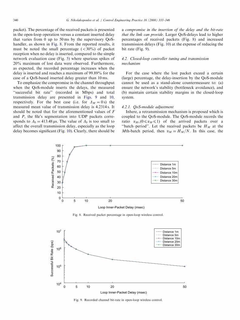
packet). The percentage of the received packets is presentedin the open-loop operation versus a constant inserted delaythat varies from 0 up to 50ms by the supervisory QoS-handler, as shown in Fig. 8. From the reported results, itmust be noted the small percentage ðo30%Þ of packetreception when no delay is inserted, compared to the simplenetwork evaluation case (Fig. 5) where spurious spikes of20% maximum of lost data were observed. Furthermore,as expected, the recorded percentage increases when thedelay is inserted and reaches a maximum of 99.89% for thecase of a QoS-based inserted delay greater than 10ms.
To emphasize the compromise in the channel throughputwhen the QoS-module inserts the delays, the measured‘‘successful bit rate’’ (recorded in Mbps) and totaltransmission delay are presented in Figs. 9 and 10,respectively. For the best case (i.e. for DM ¼ 0 s) themeasured mean value of transmission delay is 4.2314 s. Itshould be noted that for the aforementioned values of F
and P, the file’s segmentation into UDP packets corre-sponds to D0 ¼ 413:48ms. The value of D0 is too small toaffect the overall transmission delay, especially as the loopdelay becomes significant (Fig. 10). Clearly, there should be
0 5 10 200
10
20
30
40
50
60
70
80
90
100
Loop Inner-Pack
Receiv
ed P
ackets
(%
)
Fig. 8. Received packet percentage
0 5 10 20104
105
106
107
Loop Inner-Pa
Succe
ssfu
l B
it R
ate
(bp
s)
Fig. 9. Recorded channel bit-rate
a compromise in the insertion of the delay and the bit-rate
that the link can provide. Larger QoS-delays lead to higherpercentages of received packets (Fig. 8) and increasedtransmission delays (Fig. 10) at the expense of reducing thebit rate (Fig. 9).
4.2. Closed-loop controller tuning and transmission
mechanism
For the case where the lost packet exceed a certain(large) percentage, the delay-insertion by the QoS-modulecannot be used as a stand-alone countermeasure to: (a)ensure the network’s stability (bottleneck avoidance), and(b) maintain certain stability margins in the closed-loopsystem.
4.2.1. QoS-module adjustment
Inhere, a retransmission mechanism is proposed which iscoupled to the QoS-module. The QoS-module records theratio aM ; ð0paMp1Þ of the arrived packets over a‘‘batch–period’’. Let the received packets be HM at theMth-batch period, then aM ¼ HM=N. In this case, the
50
et Delay (msec)
Distance 1m
Distance 5m
Distance 30m
Distance 20m
Distance 10m
in open-loop wireless control.
50
cket Delay (msec)
Distance 1m
Distance 5mDistance 10mDistance 20mDistance 30m
in open-loop wireless control.

ARTICLE IN PRESS
0 5 10 20 50100
101
102
103
Loop Inner-Packet Delay (msec)
Tra
nsm
issio
n D
ela
y (
sec)
Distance 1m
Distance 5m
Distance 10m
Distance 20m
Distance 30m
Fig. 10. Total transmission delay in open-loop wireless control.
#0 #1 #2 #N-1
ClientM-Batch (M+1)-Batch
#0 #1
Server
#N-1
#0 #0
�M �M
#1 #1 #N-1 #N-1
�M+1 �M+1 �M+1 �M+1
Fig. 11. Data packet timing diagram w./QoS optimization and retransmission.
G. Nikolakopoulos et al. / Control Engineering Practice 16 (2008) 333–346 341
client: (1) adjusts the inner packet delay DMþ1, and (2)retransmits each packet lM ¼ d1=aMe-times, as shown inFig. 11 for l ¼ 2.
From a statistical point of view, based on thisretransmission the receiving side should receive almost alltransmitted packets ðlMaM ’ 1Þ over the ðM þ 1Þth batch.However, this occurs over a larger time span of
TMþ1t ¼ lMNðD0 þ DMþ1Þ.
Indirectly, this time-extension results in an equivalentlengthening of the d1 and d2 latency times, shown in Fig. 1.Subsequently, the maximum delay dðkÞ can increasedrastically and there is a chance that the controllerdesigned for smaller delays may not be able to stabilizethe system. This dictates the tuning of the controllerparameters in order to accommodate the new inserteddelays.
This tuning with the QoS-module described aboveoccurs at the end of each ‘‘batch’’, while an estimationfor the network’s performance for the same period isalso provided. This procedure alleviates the traffic loadsince the delays introduced in the transmission processreduce the requirements in bandwidth. On the other hand,
the retransmission scheme ‘‘decelerates’’ the controlprocess, increasing the possibility of leading the systeminto instability. Therefore, the tuning needs to be simpli-fied in order to balance the overhead introduced in thecontrol procedure and the deterioration of the network’sstatus.
4.2.2. Controller–module adjustment
Towards this goal, an ad hoc procedure is employed; atthe end of a ‘‘batch’’ tuning period, the controller’s gainKMþ1 is adapted according to the network performancemetrics at this batch, in order to guarantee a certain degreeof stability. More specifically, assume that over theðM þ 1Þth batch the number lM of retransmissions andthe inner packet delay DMþ1 have been determined by theQoS-module. Let the recorded delays for such a situationbe bounded in the interval [dmin; dmax].Accordingly the discrete delays belong to the set Il
shown in the following equation:
Il ¼ lM
dmin
TMþ1s
& ’; . . . ; lM
dmax
TMþ1s
& ’( ), (9)

ARTICLE IN PRESSG. Nikolakopoulos et al. / Control Engineering Practice 16 (2008) 333–346342
where TMþ1s is the sampling rate for the ðM þ 1Þth batch
period and d:e is the ceiling function.The controller’s objective for the ðM þ 1Þth batch is not
only to stabilize the system and henceforth to satisfy theLMIs from Eq. (8), for I ¼ Il but also to address thesystem’s performance by decreasing the system’s sensitiv-ity. This statement can be formulated as: Select KMþ1 thatminimizes the following cost:
S ¼1
1þ CðsI � AÞ�1BKMþ1
,
subject to the ‘‘LMI’’ constraints:
Pi ATi Pj
PjAi Pj
24
3540; 8ði; jÞ 2 Il � Il, ð10Þ
Pi40; 8i 2 Il, ð11Þ
� KMþ140. ð12Þ
This problem is transformed to: Compute KMþ1 such that,
KMþ1 : maxKMþ1o0
CðsI � AÞ�1BKMþ1, (13)
subject to the LMI–constraints of (10)–(12).Since the cost in (13) can be made arbitrarily large by
decreasing KMþ1, the only restriction to the selection ofKMþ1 is the satisfaction of (10)–(12). Henceforth, theproblem is similarly restated as:
Select the minimum KMþ1 that satisfies the set of LMIsin (10)–(12).
Because of K being a scalar, a simplified feasibility searchalgorithm can be employed for this problem. A typicalpseudocode of this algorithm appears in Table 2. LetKMþ1ðjÞ be the KMþ1 value at the jth iteration of thealgorithm; assume that this value satisfies the LMIs(10)–(12).
4.3. Experimental closed–loop studies
The aforementioned controller is applied in a prototypeWNCS. The controlled plant corresponds to a sampledðTs ¼ 150msÞ continuous system with a transfer functionof 103=ðsþ 10Þ3. The selected Ts-period is large enough tocover the time needed to transfer the control command andthe system response between the client and the server side.For simplicity reasons, rather than adjusting the innerpacket delay, the QoS-module adjusts only the lM factoraffecting the retransmissions. The parameters used for theexperiment are: P ¼ 400B, DM fixed, D0 þ DM ¼ 150msand N ¼ 20=Ts. However, due to the QoS-module and the
Table 2
Simplified feasibility search algorithm
1 KMþ1ðj þ 1Þ ¼ KMþ1ðjÞ � DðKMþ1Þ
2 If (10)–(12) are satisfied with KMþ1ðj þ 1Þ, go to 1
3 DðKMþ1Þ ¼ �DðKMþ1Þ
2
4 If DðKMþ1Þp� ’ 0 stop, else go to 1
retransmission mechanism adopted, the actual value of theclosed-loop sampling period TM
s is updated at the end ofeach batch tuning period according to:
TMþ1s ¼ lMðD0 þ DMÞ ¼ lMTs. (14)
Based on Eq. (14), the discrete delay set described byEq. (9) is simplified into
Il ¼ lM
dmin
lMTs
& ’; . . . ; lM
dmax
lMTs
� �( ). (15)
The goal of the presented research focuses on the study ofthe proposed optimization scheme in near–congestionconditions. The experiment consists of two nodes thatunder normal operation would exchange small, periodicalamount of control data and consequently would havelimited bandwidth requirements. Therefore, in order toexamine the behavior of the control process in a highlycompetitive environment, exogenous traffic correspondingto 4Mbps throughput is inserted artificially on the Wi-Filink. The extensive runs of the open-loop reveal that theQoS-module has encountered four distinct ratios aM
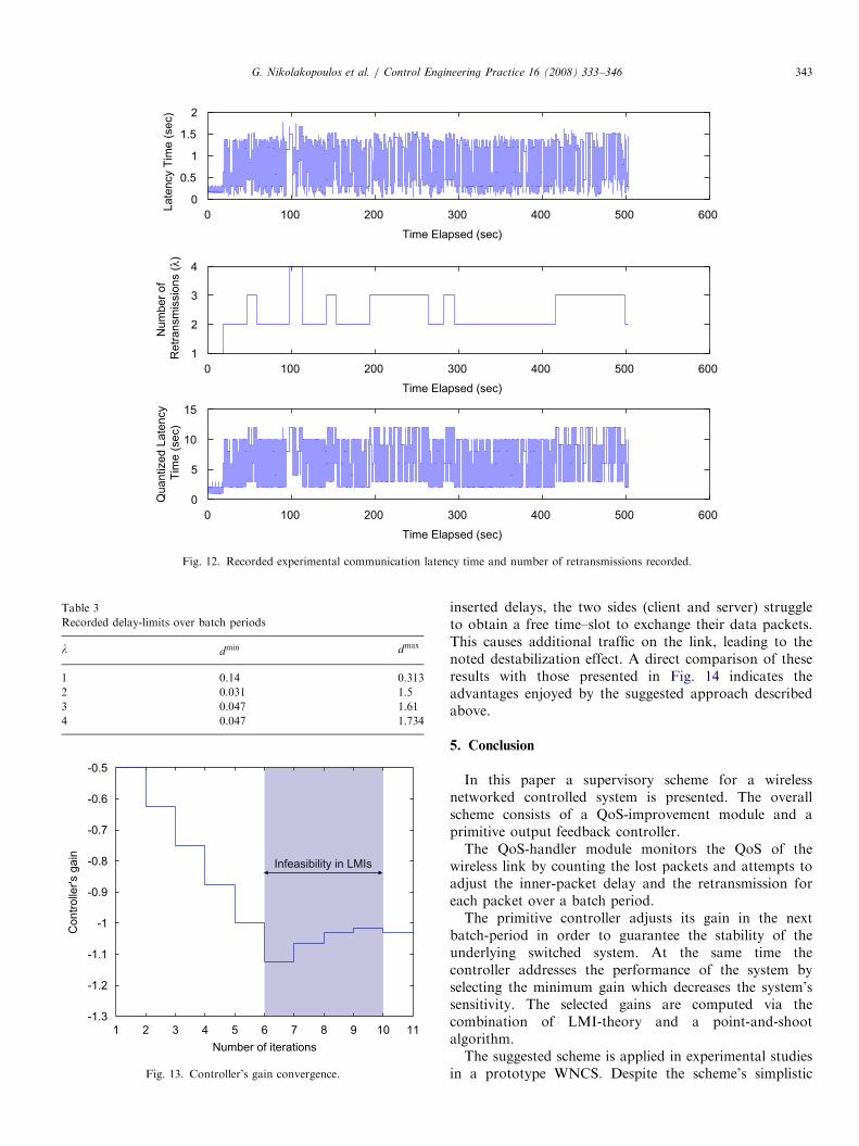
according to the arrived packets. The worst case amountsto receiving 29% of the packets within one batch periodðaM ¼ 0:29Þ, and accordingly lM 2 f1; 2; 3; 4g ð¼ d1=aMeÞ,as shown in Fig. 12.The top portion in Fig. 12 corresponds to d1 þ d2, the
middle refers to the lM -factor, while the bottom partcorresponds to lMdðd1 þ d2Þ=lMTMþ1
s e. For each lM thedelays dmin and dmax that have been measured over thosebatch periods are recorded. These measurements arehighlighted in Table 3.Based on the Table’s entries the sets Il are I1 ¼ f1; 2g,
I2 ¼ f2; 4; 6; 8; 10g, I3 ¼ f3; 6; 9; 12g, and I4 ¼ f4; 8; 12g.The minimum K for each set is
K1 ¼ �1:0234; K2 ¼ �0:65625; K3 ¼ �0:656,
K4 ¼ �0:625.
A typical convergence for the simplified search algorithmfor the first case ðK1; I1Þ appears in Fig. 13.The switched-controller is applied to the prototype
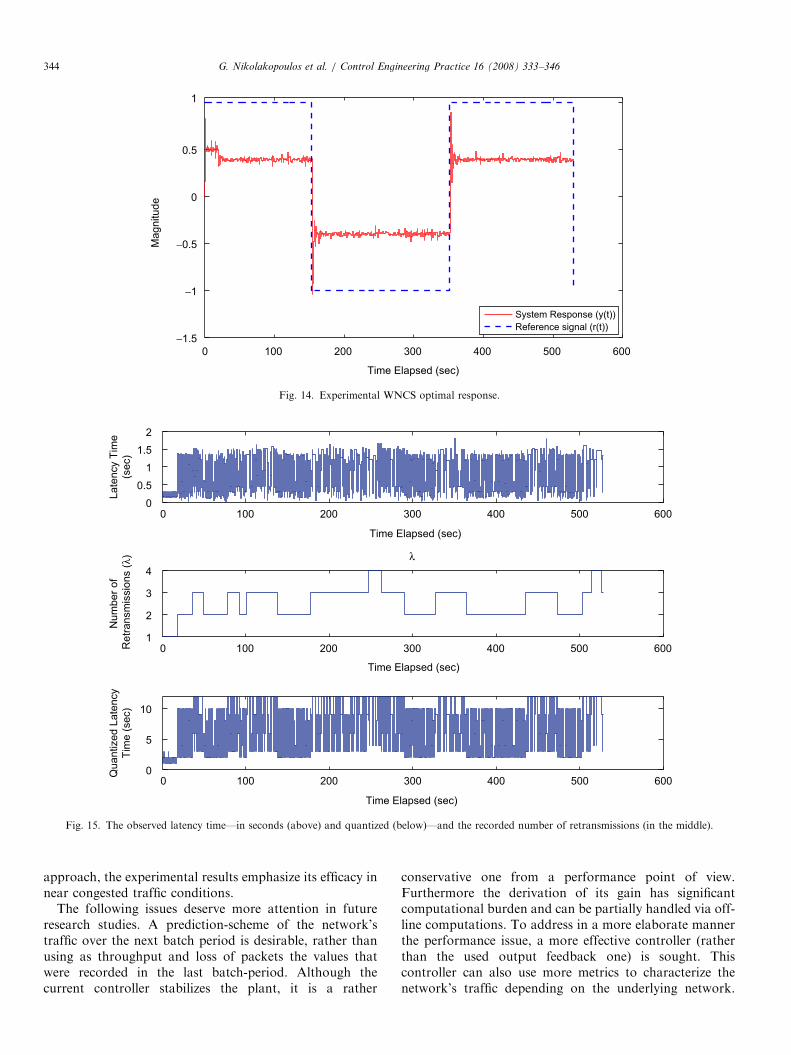
system. The system’s response appears in Fig. 14. Theeffect of the controller tuning is evident on the system’sresponse. The sudden deviations observed in the system’sresponse are a result of the controller’s gain adaptation,according to the network’s performance.In Fig. 15 the observed latency time is outlined for each
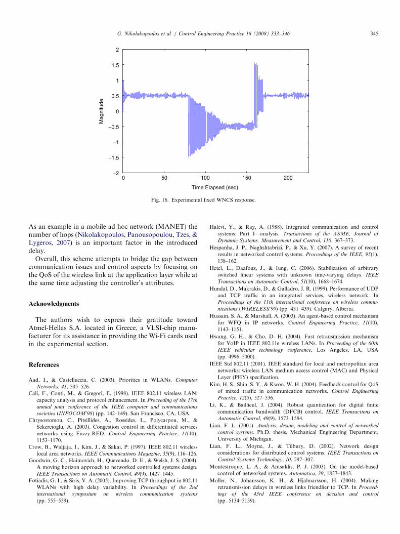
experimental case. The dependence of system’s response onthe network performance for the second case is dominantsince as the reception conditions worsen, the systemswitches its operation from I2 to I3 and I4.For comparison purposes, a similar system response is
provided in Fig. 16 with fixed gain K ¼ �1, where there areno provisions for handling the QoS-issue. It should benoted the destabilization effect that takes place after the80th second, where there is considerable loss of packets.Since there are neither retransmissions nor any artificial
ARTICLE IN PRESS
0 100 200 300 400 500 600
0
0.5
1
1.5
2
Time Elapsed (sec)
Late
ncy T
ime (
sec)
0 100 200 300 400 500 600
1
2
3
4
Time Elapsed (sec)
Num
ber
of
Retr
ansm
issio
ns (
λ)
0 100 200 300 400 500 600
0
5
10
15
Time Elapsed (sec)
Quantized L
ate
ncy
Tim
e (
sec)
Fig. 12. Recorded experimental communication latency time and number of retransmissions recorded.
Table 3
Recorded delay-limits over batch periods
l dmin dmax
1 0.14 0.313
2 0.031 1.5
3 0.047 1.61
4 0.047 1.734
Infeasibility in LMIs
-0.5
-0.6
-0.7
-0.8
-0.9
-1
-1.1
-1.2
-1.31 2 3 4 5 6 7 8 9 10 11
Number of iterations
Contr
olle
r's g
ain
Fig. 13. Controller’s gain convergence.
G. Nikolakopoulos et al. / Control Engineering Practice 16 (2008) 333–346 343
inserted delays, the two sides (client and server) struggleto obtain a free time–slot to exchange their data packets.This causes additional traffic on the link, leading to thenoted destabilization effect. A direct comparison of theseresults with those presented in Fig. 14 indicates theadvantages enjoyed by the suggested approach describedabove.
5. Conclusion
In this paper a supervisory scheme for a wirelessnetworked controlled system is presented. The overallscheme consists of a QoS-improvement module and aprimitive output feedback controller.The QoS-handler module monitors the QoS of the
wireless link by counting the lost packets and attempts toadjust the inner-packet delay and the retransmission foreach packet over a batch period.The primitive controller adjusts its gain in the next
batch-period in order to guarantee the stability of theunderlying switched system. At the same time thecontroller addresses the performance of the system byselecting the minimum gain which decreases the system’ssensitivity. The selected gains are computed via thecombination of LMI-theory and a point-and-shootalgorithm.The suggested scheme is applied in experimental studies
in a prototype WNCS. Despite the scheme’s simplistic
ARTICLE IN PRESS
0 100 200 300 400 500 600
−1.5
−1
−0.5
0
0.5
1
Time Elapsed (sec)
Magnitude
System Response (y(t))
Reference signal (r(t))
Fig. 14. Experimental WNCS optimal response.
0 100 200 300 400 500 6000
0.5
1
1.5
2
Time Elapsed (sec)
Late
ncy T
ime
(sec)
0 100 200 300 400 500 6001
2
3
4
λ
Time Elapsed (sec)
Num
ber
of
Retr
ansm
issio
ns (
λ)
0 100 200 300 400 500 6000
5
10
Time Elapsed (sec)
Quantized L
ate
ncy
Tim
e (
sec)
Fig. 15. The observed latency time—in seconds (above) and quantized (below)—and the recorded number of retransmissions (in the middle).
G. Nikolakopoulos et al. / Control Engineering Practice 16 (2008) 333–346344
approach, the experimental results emphasize its efficacy innear congested traffic conditions.
The following issues deserve more attention in futureresearch studies. A prediction-scheme of the network’straffic over the next batch period is desirable, rather thanusing as throughput and loss of packets the values thatwere recorded in the last batch-period. Although thecurrent controller stabilizes the plant, it is a rather
conservative one from a performance point of view.Furthermore the derivation of its gain has significantcomputational burden and can be partially handled via off-line computations. To address in a more elaborate mannerthe performance issue, a more effective controller (ratherthan the used output feedback one) is sought. Thiscontroller can also use more metrics to characterize thenetwork’s traffic depending on the underlying network.
ARTICLE IN PRESS
0 50 100 150 200−2
−1.5
−1
−0.5
0
0.5
1
1.5
2
Time Elapsed (sec)
Magnitude
Fig. 16. Experimental fixed WNCS response.
G. Nikolakopoulos et al. / Control Engineering Practice 16 (2008) 333–346 345
As an example in a mobile ad hoc network (MANET) thenumber of hops (Nikolakopoulos, Panousopoulou, Tzes, &Lygeros, 2007) is an important factor in the introduceddelay.
Overall, this scheme attempts to bridge the gap betweencommunication issues and control aspects by focusing onthe QoS of the wireless link at the application layer while atthe same time adjusting the controller’s attributes.
Acknowledgments
The authors wish to express their gratitude towardAtmel-Hellas S.A. located in Greece, a VLSI-chip manu-facturer for its assistance in providing the Wi-Fi cards usedin the experimental section.
References
Aad, I., & Castelluccia, C. (2003). Priorities in WLANs. Computer
Networks, 41, 505–526.
Cali, F., Conti, M., & Gregori, E. (1998). IEEE 802.11 wireless LAN:
capacity analysis and protocol enhancement. In Proceeding of the 17th
annual joint conference of the IEEE computer and communications
societies (INFOCOM’98) (pp. 142–149). San Francisco, CA, USA.
Chrysostomou, C., Pitsillides, A., Rossides, L., Polycarpou, M., &
Sekercioglu, A. (2003). Congestion control in differentiated services
networks using Fuzzy-RED. Control Engineering Practice, 11(10),
1153–1170.
Crow, B., Widjaja, I., Kim, J., & Sakai, P. (1997). IEEE 802.11 wireless
local area networks. IEEE Communications Magazine, 35(9), 116–126.
Goodwin, G. C., Haimovich, H., Quevendo, D. E., & Welsh, J. S. (2004).
A moving horizon approach to networked controlled systems design.
IEEE Transactions on Automatic Control, 49(9), 1427–1445.
Fotiadis, G. I., & Siris, V. A. (2005). Improving TCP throughput in 802.11
WLANs with high delay variability. In Proceedings of the 2nd
international symposium on wireless communication systems
(pp. 555–559).
Halevi, Y., & Ray, A. (1988). Integrated communication and control
systems: Part I—analysis. Transactions of the ASME, Journal of
Dynamic Systems, Measurement and Control, 110, 367–373.
Hespanha, J. P., Naghshtabrizi, P., & Xu, Y. (2007). A survey of recent
results in networked control systems. Proceedings of the IEEE, 95(1),
138–162.
Hetel, L., Daafouz, J., & Iung, C. (2006). Stabilization of arbitrary
switched linear systems with unknown time-varying delays. IEEE
Transactions on Automatic Control, 51(10), 1668–1674.
Hundal, D., Makrakis, D., & Galladro, J. R. (1999). Performance of UDP
and TCP traffic in an integrated services, wireless network. In
Proceedings of the 11th international conference on wireless commu-
nications (WIRELESS’99) (pp. 431–439). Calgary, Alberta.
Hussain, S. A., & Marshall, A. (2003). An agent-based control mechanism
for WFQ in IP networks. Control Engineering Practice, 11(10),
1143–1151.
Hwang, G. H., & Cho, D. H. (2004). Fast retransmission mechanism
for VoIP in IEEE 802.11e wireless LANs. In Proceeding of the 60th
IEEE vehicular technology conference, Los Angeles, LA, USA
(pp. 4996–5000).
IEEE Std 802.11 (2001). IEEE standard for local and metropolitan area
networks: wireless LAN medium access control (MAC) and Physical
Layer (PHY) specification.
Kim, H. S., Shin, S. Y., & Kwon, W. H. (2004). Feedback control for QoS
of mixed traffic in communication networks. Control Engineering
Practice, 12(5), 527–536.
Li, K., & Baillieul, J. (2004). Robust quantization for digital finite
communication bandwidth (DFCB) control. IEEE Transactions on
Automatic Control, 49(9), 1573–1584.
Lian, F. L. (2001). Analysis, design, modeling and control of networked
control systems. Ph.D. thesis, Mechanical Engineering Department,
University of Michigan.
Lian, F. L., Moyne, J., & Tilbury, D. (2002). Network design
considerations for distributed control systems. IEEE Transactions on
Control Systems Technology, 10, 297–307.
Montestruque, L. A., & Antsaklis, P. J. (2003). On the model-based
control of networked systems. Automatica, 39, 1837–1843.
Moller, N., Johansson, K. H., & Hjalmarsson, H. (2004). Making
retransmission delays in wireless links friendlier to TCP. In Proceed-
ings of the 43rd IEEE conference on decision and control
(pp. 5134–5139).
ARTICLE IN PRESSG. Nikolakopoulos et al. / Control Engineering Practice 16 (2008) 333–346346
Nair, G., & Evans, R. (2000). Stabilization with data-rate-limited
feedback: Tightest attainable bounds. Systems and Control Letters,
41(1), 49–56.
Nair, G., & Evans, R. (2003). Exponential stability of finite-dimensional
linear systems with limited data rates. Automatica, 39(4), 585–593.
Nair, G., Evans, R., Mareels, I., & Moran, W. (2003). Feedback data rates
for nonlinear systems. In Proceedings of the European control
conference (Vol. 112), Cambridge, UK.
Nair, G. N., Fagnani, F., Zampieri, S., & Evans, R. J. (2007). Feedback
control under data rate constraints: An overview. Proceedings of the
IEEE, 95(1), 108–137.
Natkaniec, M., & Pach, A. (2000). An analysis of the backoff mechanism
used in EEE 802.11 networks. In Proceedings of the 5th IEEE
symposium on computer and communications, Antibes-Juan les Prins,
France.
Nikolakopoulos, G., Panousopoulou, A., Tzes, A., & Lygeros, J. (2007).
Multi-hopping induced gain scheduling for wireless networked
controlled systems. Asian Journal of Control, 9(4), to appear. A shorter
version appears in the proceedings of the 44th IEEE conference on
decision and control (CDC-ECC’05) (pp. 470–475). Seville Spain,
December 2005.
Overstreet, J., & Tzes, A. (1999). An internet-based real time control
engineering laboratory. IEEE Control Systems Magazine, 99, 19–34.
Panousopoulou, A., Nikolakopoulos, G., Tzes, A., & Lygeros, J. (2006).
Recent trends on QoS for wireless networked controlled systems.
Mediterranean Journal of Computers and Networks, 2(1), 31–40.
Priscoli, F. D., & Isidori, A. (2005). A control-engineering approach to
integrated congestion control and scheduling in wireless local area
networks. Control Engineering Practice, 13(5), 541–558.
Ray, A., & Halevi, Y. (1988). Integrated communication and control
systems: Part II—design considerations. Transactions of the ASME,
Journal of Dynamic Systems, Measurement and Control, 110, 374–381.
Recht, B., & Andrea, R. (2004). Distributed control of systems over
discrete groups. IEEE Transactions on Automatic Control, 49(9),
1446–1542.
Sweet, C., & Sidhu, D. (1999). Performance analysis of the IEEE 802.11
wireless standard. In Proceedings of the IEEE global telecommunica-
tions conference (Globecom’99), Rio de Janeiro, Brazil.
Tanenbaum, A. S. (1996). Computer networks (3rd ed.). Englewood Cliffs,
NJ: Prentice-Hall.
Tipsuwan, Y., & Chow, M. (2003). Control methodologies in networked
control systems. Control Engineering Practice, 11(10), 1099–1111.
Tzes, A., Nikolakopoulos, G., & Koutroulis, I. (2005). Development and
experimental verification of a mobile client-centric networked con-
trolled system. European Journal of Control, 11(3), 229–241.
Van Antwerp, J. G., & Braatz, R. D. (2000). A tutorial on linear and
bilinear matrix inequalities. Journal of Process Control, 10(4), 363–385.
Walsh, G. C., Ye, H., & Bushnell, L. (2002). Stability analysis of
networked control systems. IEEE Transactions on Control Systems
Technology, 10(3), 438–446.
Wu, H., Peng, Y., Long, K., Cheng, S., & Nat, J. M. (2002). Performance
of reliable transport protocol over IEEE 802.11 wireless LAN:
Analysis and enhancement. In Proceedings of the 21st annual joint
conference of the IEEE computer and communications societies
(INFOCOM’02) (pp. 599–607). New York, NY, USA.
Wong, W. S., & Brockett, R. (1999). Systems with finite communication
bandwidth constraints-II: Stabilization with limited information feed-
back. IEEE Transactions on Automatic Control, 44(5), 1049–1053.
Xylomenos, G., & Polyzos, G. (1999). TCP and UDP performance over a
wireless LAN. In Proceedings of the 18th annual joint conference of
the IEEE computer and communications societies (INFOCOM’99)
(pp. 439–446). New York, NY, USA.
Xylomenos, G., & Polyzos, G. (2001). TCP Performance over wireless
links. IEEE Communications Magazine, 39(4), 52–58.
Related Documents