ن الرحيم الرحم بسمSUDAN UNIVERSITY OF SCIENCE AND TECHNOLOGY COLLEGE OF GRADUTE STUDIES TUNING OF FUZZY LOGIC CONTROLLER USING GENETIC ALGORITHM ضبط الخوارزمية الجينيةستخداملغامض با المنطق اتحكم مA Thesis Submitted in Partial Fulfillment of the Requirements for the Degree of Master of Science in Electrical Engineering (Microprocessors and Control) Prepared By: Mohammed Almurtada Elzein Ahmed Supervisor: Dr. Awadalla Taifour Ali Ismail April 2017

Welcome message from author
This document is posted to help you gain knowledge. Please leave a comment to let me know what you think about it! Share it to your friends and learn new things together.
Transcript

بسم هللا الرحمن الرحيم
SUDAN UNIVERSITY OF SCIENCE AND TECHNOLOGY
COLLEGE OF GRADUTE STUDIES
TUNING OF FUZZY LOGIC CONTROLLER
USING GENETIC ALGORITHM
متحكم المنطق الغامض باستخدام الخوارزمية الجينية ضبط
A Thesis Submitted in Partial Fulfillment of the Requirements for the Degree of Master
of Science in Electrical Engineering (Microprocessors and Control)
Prepared By:
Mohammed Almurtada Elzein Ahmed
Supervisor:
Dr. Awadalla Taifour Ali Ismail
April 2017

i
اآليـــــــة
قال تعالى في محكم تنزيله:
عني أن أشكر نعمتك التي أنعمت علي وعلى والدي وأن أعمل صالحا ترضاه } أوز لني رب وأدخ
ين برحمت الح ك الص باد {ك في ع
صدق هللا العظيم
(19اآلية ) سورة النمل

ii
DEDICATION
I dedicate my dissertation work to my family and many friends. A special
feeling of gratitude to my loving parents, Almortada and Sawsan whose words
of encouragement and push for tenacity ring in my ears. I also dedicate this
work to my wife, I really appreciate your help and support I have to admit
without your support I do not think I can make it through. To my son who has
been affected in every way possible by this quest.
I dedicate this work to each of those who taught me one single letter that
became a light bulb guides and lights the way in front of me. And then to all
those who encouraged me and supported me to bring this work in perfection I
ask the almighty Allah to reward them with the best reward.

iii
ACKNOWLEDGMENT
Alhamdullilah... Finally I have finished my research. I would like to
express my sincere thankful and appreciation to my supervisor Dr.Awadalla
Taifour Ali for sharing his knowledge with me and for providing me with
much guidance, support and encouragement.

iv
ABSTRACT
In this dissertation, the controller be tuned using the Genetic Algorithm
(GA) technique in MATLAB environment. The controller is designed based on
the expert knowledge of the system. For the proposed Direct Current (DC)
motor case, there are nine fuzzy rules designed for Fuzzy Logic Controller
(FLC). GA is the search technique being applied in this research to determine
the parameters of the controller. The output response of the system is obtained
by using three types of controllers, namely, Proportional Integral Derivative
(PID), FLC and FLC with GA. The results showed the better performance
achieved with GA.

v
مستخلص
في بيئة ماتالب. تم الجينية الخوارزمية باستخدام تقنية المتحكمةفي هذه األطروحة، يتم ضبط
تسعةلمحرك التيار المستمر المقترح هنالك للنظام. بالنسبةعلى اساس المعرفة الفنية المتحكمة تصميم
هذا تقنية بحث يجرى تطبيقها في هيالجينية الغامض. الخوارزميةعلى المتحكم للسيطرةقوانين
انواع من المتحكمات ثالثة النظام باستخدام استجابةتم الحصول على .لمتحكمةا ثوابتالبحث لتحديد
المتحكم الغامض و (FLC) المتحكم الغامضو (PIDالتفاضلي )-التكاملي-المتحكم التناسبي
.الجينيةالنتائج ان االداء االفضل يتحقق بواسطه الخوارزميات الجينية. وأظهرتبالخوارزميات
vi
TABLE OF CONTENTS
Page No
i اآلية
DEDICATION ii
ACKNOWLEDGEMENT iii
ABSTRACT iv
v مستخلص
TABLE OF CONTENTS vi
LIST OF ABBRIEVATIONS ix
LIST OF FIGURES x
LIST OF TABLES xii
CHAPTER ONE
INTRODUCTION
1.1 General 1
1.2 Problem Statement 2
1.3 Objectives 2
1.4 Methodology 2
1.5 Thesis Layout 2
CHAPTER TWO
LITERATURE REVIEW AND THEORETICAL BACKGROUND
2.1 Tuning 4
2.2 Fuzzy Logic Theory 4
2.2.1 Fuzzy sets 5
2.2. 2 Membership functions 5
2.3 Fuzzy Logic Controller 7
2.3.1 Preprocessing 7
2.3.2 Postprocessing 8
vii
2.3.3 Fuzzification 8
2.3.4 Fuzzy inferencing 8
2.3.5 Defuzzification 9
2.4 Types of Fuzzy Controllers 10
2.4.1 Direct controller 10
2.4.2 Supervisory control 10
2.4.3 PID adaptation 10
2.4.4 Fuzzy intervention 10
2.5 Fuzzy Controller Versus Conventional Controller 11
2.6 Genetic Algorithm 12
2.6.1 Basic steps 14
2.6.2 Parameters and operators 15
2.7 DC Motor 17
CHAPTER THREE
CONTROL SYSTEM DESIGN
3.1 Mathematical Modelling 19
3.2 PID Controller Design 21
3.3 Fuzzy Controller Design 23
3.3.1 FIS editor 24
3.3.2 Membership function editor 26
3.3.3 Rule editor 26
3.3.4 Rule viewer 29
3.3.5 Surface viewer 29
3.4 Fuzzy Controller Design With GA 29
CHAPTER FOUR
SIMULATION RESULTS
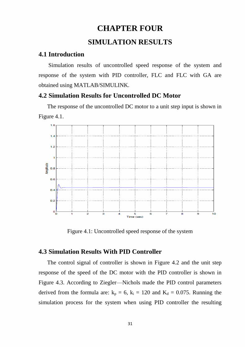
4.1 Introduction 31
4.2 Simulation Results for Uncontrolled DC Motor 31

viii
4.3 Simulation Results With PID Controller 31
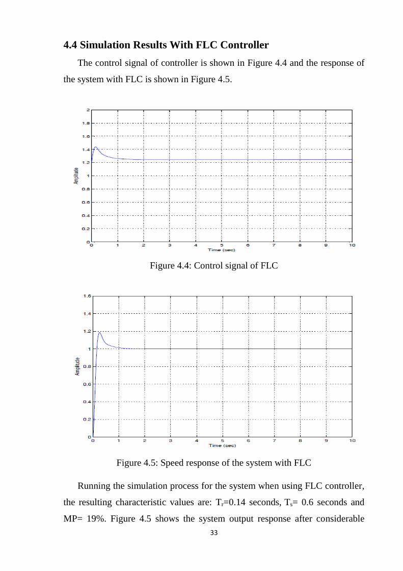
4.4 Simulation Results With FLC Controller 33
4.5 Simulation Results of FLC Controller With GA 34
4.6 Results Comparison 35
CHAPTER FIVE
CONCLUSION AND RECOMMENDATIONS
5.1 Conclusion 37
5.2 Recommendations 37
REFERENCES 38
APPENDICES 39
APPENDIX A : SYSTEM MODEL PARAMETERS 39
APPENDIX B: MATLAB SOURCE CODE 40

ix
LIST OF ABBREVIATIONS
COA Centre Of Area
COG Centre Of Gravity
COS Centre Of Sum
DC Direct Current
ECOA Extended Centre Of Area
EMF Electro-Motive Force
EQM Extended Quality Method
FCD Fuzzy Clustering Defuzzification
FIS Fuzzy Interface System
FLC Fuzzy Logic Controller
FM Fuzzy Mean
FOM First Of Maximum
GA Genetic Algorithm
GUI Graphical User Interface
LN Large Negative
LP Large Positive
MF Membership Function
MN Medium Negative
MP Medium Positive
PID Proportional Integral Derivative
SN Small Negative
SP Small Positive
WFM Weighted Fuzzy Mean
Z Zero

x
LIST OF FIGURES
Figure Title Page
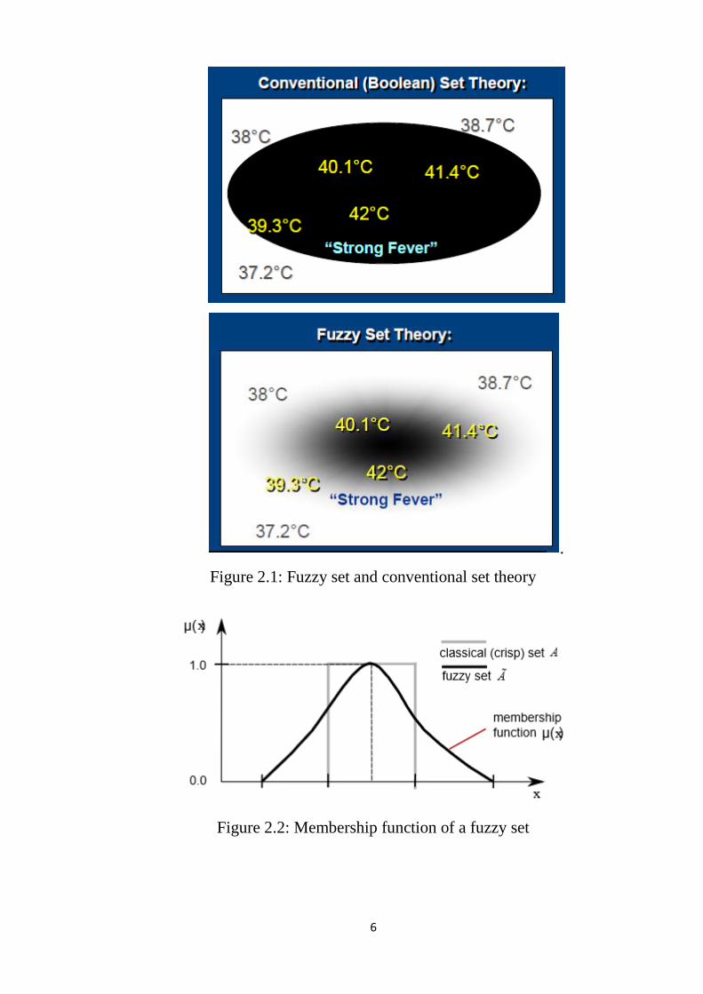
2.1 Fuzzy set and conventional set theory 6
2.2 Membership function of a fuzzy set 6
2.3 Structure of fuzzy logic controller 8
2.4 Example of fuzzification 9
2.5 Direct controller 11
2.6 Supervisory control 11
2.7 PID adaptation 11
2.8 Fuzzy intervention 12
2.9 A Procedure of simple GA 11
2.10 Basic steps of a genetic algorithm 11
2.11 Crossover 11
2.12 Mutation 17
3.1 DC motor model 11
3.2 Conventional feedback control system 11
3.3 MATLAB/SIMULINK model of system using PID controller 11
3.4 Fuzzy controller design 11
3.5 Fuzzy inference system 25
3.6 FIS editor 25
3.7 Membership function editor for error 11
3.8 Membership function editor for change in error 27
3.9 Membership function editor for control 28
3.10 Rule editor 28
3.11 Rule viewer 29
3.12 Surface viewer 30
3.13 Fuzzy controller design with GA 30

xi
4.1 Uncontrolled speed response of the system 31
4.2 Control signal of PID controller 32
4.3 Speed response of the system with PID controller 32
4.4 Control signal of FLC 33
4.5 Speed response of the system with FLC 33
4.6 Control signal of FLC with GA 34
4.7 Speed response of the system with fuzzy controller using GA 35
4.8 Comparative responses 35

xii
LIST OF TABLES
Table Title Page
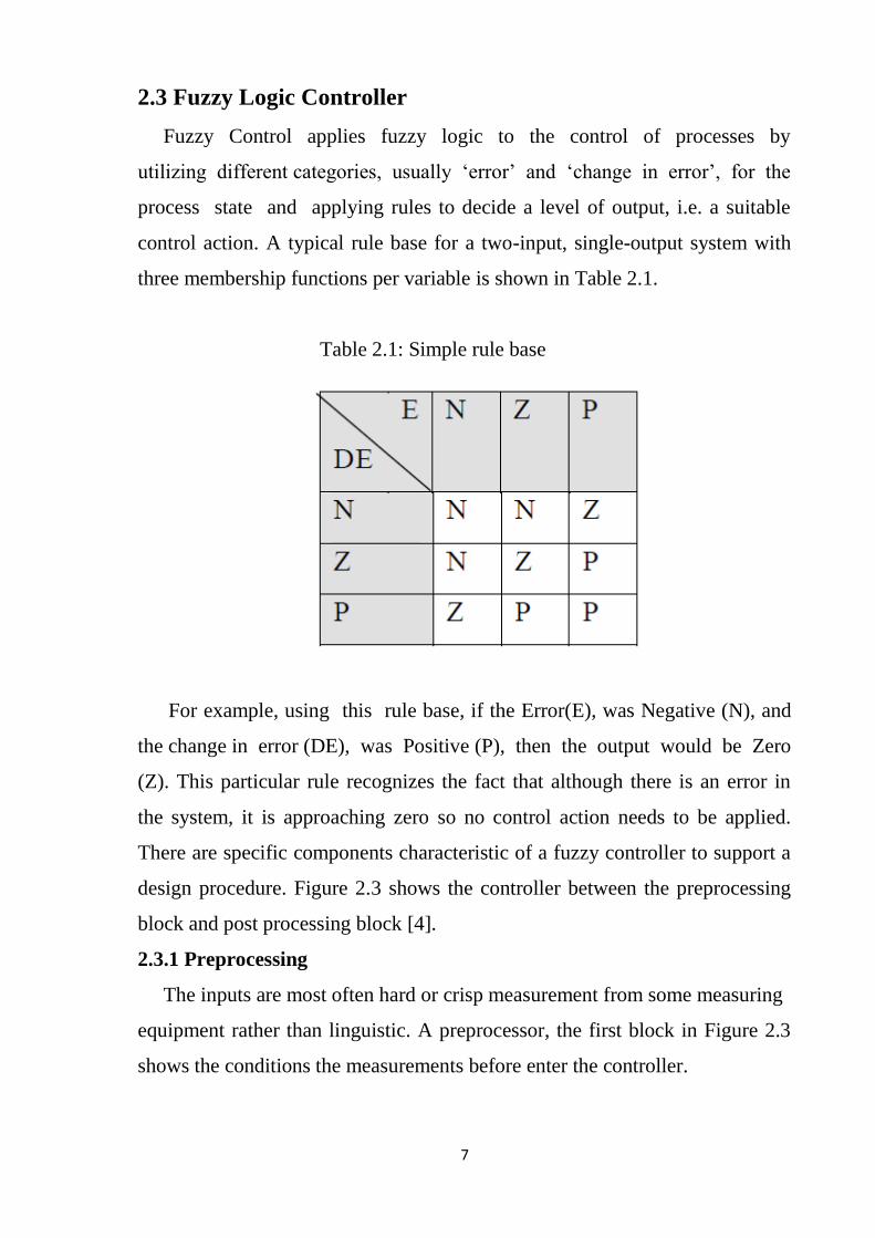
2.1 Simple rule base 7
3.1 Fuzzy rules 27
4.1 Comparison of results 36

1
CHAPTER ONE
INTRODUCTION
1.1 General
Control system in the general plant plays an important role in the
development of robotic and mechatronics. Many approaches were proposed to
control various systems such as fuzzy control, robust control, genetic
algorithms based control and model reference control. Artificial intelligent
system based fuzzy method has an active research topic in automation and
control theory. It provides a systematic method to incorporate human
experience and implement nonlinear algorithm characterized by a series of
linguistic statement into the controller. Fuzzy logic controller used fuzzy logic
as design methodology which can be applied in developing linear and
nonlinear system for embedded control unlike the classic logic approach,
which requires a deep understand of the system, exact equations and precise
numeric value, fuzzy logic incorporates an alternative way of thinking which
allows one to model complex systems using a high level of abstraction
originated form accumulated knowledge and experience [1].
Since fuzzy logic has proven to be a very useful tool for representing
human knowledge by means of mathematical expressions, the optimization of
the involved parameters has been one of the most investigated problems in the
theory of fuzzy expert systems. Typically, fuzzy systems have two
components: a discrete one, the rules, and a continuous one on the other hand,
the so-called fuzzy sets. Genetic algorithms are optimization methods which
are based on the mechanisms of natural evolution, such as selection, mutation,
or sexual reproduction. Genetic algorithms were introduced approximately 25
years ago and turned out to be a very promising approach to the solution of
many problems in artificial intelligence. Very many recent publications
concern with the optimization of fuzzy sets parameters with Genetic
Algorithms (GAs).
2
1.2 Problem Statement
The life cycle of a control system demands several optimizations in
several steps. Probably the most demanding steps are those in the phases of
process modeling and controller design. Sometimes these optimizations are
very simple, based on experiences, tuning rules or simulation trials. Sometimes
better result are obtained by conventional optimization techniques. This
approach is extremely important for control system with lower number loops
and with called parametric controllers. However more advanced control
algorithms contain usually much more parameters, which must be
appropriately tuned. More complex control algorithms result in better
efficiency, when systems are complex, nonlinear or time varying,
multivariable, highly oscillating, with significant delays etc. Conventional
optimization algorithms are not able to properly handle such problems, so
there is a constant search for new and better methods.
1.3 Objectives
The objectives of this research are:
• To provide a profound introduction to both fuzzy logic and genetic
algorithms and to explore the possibilities to combine the two
paradigms.
• To Demonstrates the effectiveness of using genetic algorithms to
optimize fuzzy logic control systems.
1.4 Methodology
• Develop the mathematical model of the DC motor.
• Build the MATLAB/SIMULINK complete system with different
controllers.
• Evaluate the performance of the system based on simulation results.
1.5 Thesis Layout
This thesis consists of five chapters including chapter one. Chapter two
presents the literature review and theoretical background. Chapter three

3
concentrates on the controller design. Chapter four gives the simulation results.
Finally in chapter five handle the recommendations for future work in this area
are given together with a conclusion on the work done in this study.
4
CHAPTER TWO
LITERATURE REVIEW AND THEORETICAL
BACKGROUND
2.1 Tuning
The process of selecting the controller parameters to meet given
performance specification is known as controller tuning. The control system
performs poor in characteristics and even it becomes unstable, if improper
values of the controller tuning constants are used. So it becomes necessary to
tune the controller parameters to achieve good control performance with the
proper choice of tuning constants. The performance of a fuzzy logic controller
depends on its control rules, membership functions and scaling factors for
each variable. Hence, it is very important to adjust these parameters to the
process to be controlled [2].
2.2 Fuzzy Logic Theory
Fuzzy logic emerged as a consequence of the 1965 proposal of fuzzy set
theory by Lotfi Zadeh. Though fuzzy logic has been applied to many fields,
from control theory to artificial intelligence, it still remains controversial among
most statisticians, who prefer Bayesian logic, and some control engineers, who
prefer traditional two-valued logic. Fuzzy logic is against aristotelian logic.
According to aristotelian logic, for a given proposition or state only have two
logical values: true-false, black-white, 1-0. However in real life, things are not
necessary be either black or white. In fact most of the times are grey. Thus, in
many practical situations, it is convenient to consider intermediate logical
values.
Japanese companies developed a wide range of products using fuzzy logic,
ranging from washing machines to autofocus cameras and industrial air
conditioners. Also, some work performed on fuzzy logic systems in the US and
Europe, and a number of products were developed using fuzzy logic controllers.

5
However, little has been said about the technology in recent years, which
implies that it has either become such an ordinary tool that it is no longer worth
much comment, or it turned out to be an industrial fad that has now generally
died out [3].
2.2.1 Fuzzy sets
Fuzzy logic starts with the concept of a fuzzy set. Fuzzy sets are sets without
crisp and clearly defined boundary. It contains elements with only a partial
degree of membership. Fuzzy set is an extension of the classical set. In classical
set theory, the membership of elements in a set is assessed in binary terms
according to a bivalent condition — it wholly includes or excludes any given
element. By contrast, fuzzy set theory permits the gradual assessment of the
membership of elements in a set; this is described with the aid of a membership
function valued in the real unit interval [0, 1] as shown in Figure 2.1. The fuzzy
set theory can be used in a wide range of domains in which information is
incomplete or imprecise, such as bioinformatics. The following statement lays
the foundation of fuzzy logic:
In the world of fuzzy logic, the truth of any statement becomes only a matter of
degree.
2.2.2 Membership functions
A Membership Function (MF) is a curve that defines the degree of
membership (lies between 0 and 1) that a value in the input universe of
discourse (input space) is mapped to as shown in Figure 2.2. The simplest
membership functions are formed using straight lines. Of these, the most
commonly used MFs include the triangular MF and the trapezoidal MF, which
is really a truncated triangular MF. If X is the universe of discourse and its
elements are denoted by x, then µA(x) is defined as the membership value or
degree of membership of x in the MF of the linguistic variable A. The linguistic
variables are usually labelled Large Negative (LN), Medium Negative (MN),
Small Negative (SN), Zero (Z), Small Positive (SP), Medium Positive (MP) and
Large Positive (LP).
6
.
Figure 2.1: Fuzzy set and conventional set theory
Figure 2.2: Membership function of a fuzzy set
7
2.3 Fuzzy Logic Controller
Fuzzy Control applies fuzzy logic to the control of processes by
utilizing different categories, usually ‘error’ and ‘change in error’, for the
process state and applying rules to decide a level of output, i.e. a suitable
control action. A typical rule base for a two-input, single-output system with
three membership functions per variable is shown in Table 2.1.
Table 2.1: Simple rule base
For example, using this rule base, if the Error(E), was Negative (N), and
the change in error (DE), was Positive (P), then the output would be Zero
(Z). This particular rule recognizes the fact that although there is an error in
the system, it is approaching zero so no control action needs to be applied.
There are specific components characteristic of a fuzzy controller to support a
design procedure. Figure 2.3 shows the controller between the preprocessing
block and post processing block [4].
2.3.1 Preprocessing
The inputs are most often hard or crisp measurement from some measuring
equipment rather than linguistic. A preprocessor, the first block in Figure 2.3
shows the conditions the measurements before enter the controller.

8
Figure 2.3: Structure of fuzzy logic controller
2.3.2 Postprocessing
The postprocessing block often contains an output gain that can be tuned
and also become as an integrator.
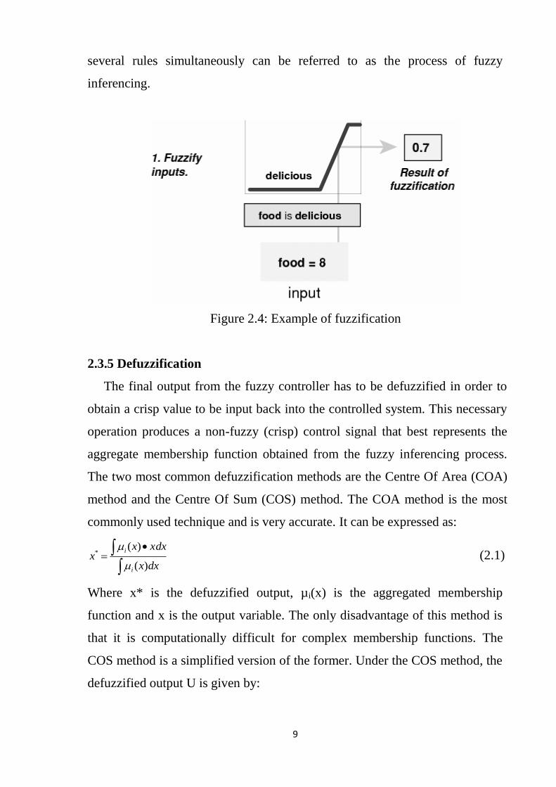
2.3.3 Fuzzification
A fuzzy controller will receive crisp inputs on its input or communications
port and initially fuzzify them. Each system input is divided into sets of
membership functions which are overlapping. The predefined membership
functions cover the whole range of values for an input and will then define a
degree of truth for every point in the range of values [5]. The input is always a
crisp numerical value limited to a range of values of the input variable and the
output is a fuzzy degree of membership (always in the interval between 0 and
1) corresponding to one or more membership functions. A diagram of an
example of fuzzification is shown in Figure 2.4.
2.3.4 Fuzzy inferencing
Fuzzy rules combine two or more input fuzzy sets, called the anecedents
sets, and associate an output with them, or consequent set. Due to the partial
matching attribute of fuzzy control rules and the fact that the preconditions of
the rules do overlap, usually more than one fuzzy rule will fire off at one time.
The methodology in deciding what control action to take as a result of firing
9
several rules simultaneously can be referred to as the process of fuzzy
inferencing.
Figure 2.4: Example of fuzzification
2.3.5 Defuzzification
The final output from the fuzzy controller has to be defuzzified in order to
obtain a crisp value to be input back into the controlled system. This necessary
operation produces a non-fuzzy (crisp) control signal that best represents the
aggregate membership function obtained from the fuzzy inferencing process.
The two most common defuzzification methods are the Centre Of Area (COA)
method and the Centre Of Sum (COS) method. The COA method is the most
commonly used technique and is very accurate. It can be expressed as:
•
dxx
xdxxx
i
i
)(
)(*
(2.1)
Where x* is the defuzzified output, µi(x) is the aggregated membership
function and x is the output variable. The only disadvantage of this method is
that it is computationally difficult for complex membership functions. The
COS method is a simplified version of the former. Under the COS method, the
defuzzified output U is given by:

10
m
i
iz
i
m
i
iz z
U
1
,
1
,
(2.2)
Where m is the number of overlapped rules that are fired simultaneously, µz,i is
the membership value of the output for the ith fired rule and iz is specific crisp
(numerical) value assigned to each linguistic variable. There are many
different methods of defuzzification available, including the following [6]:
1. Centre Of Area (COA).
2. Centre Of Gravity (COG).
3. Extended Centre Of Area (ECOA).
4. Extended Quality Method (EQM).
5. Fuzzy Clustering Defuzzification (FCD).
6. Fuzzy Mean (FM).
7. First Of Maximum (FOM).
8. Weighted Fuzzy Mean (WFM).
2.4 Types of Fuzzy Controllers
The main types of fuzzy controllers are:
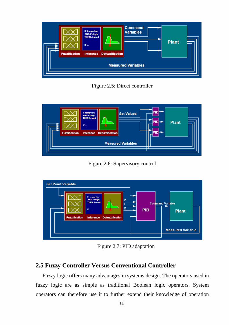
2.4.1 Direct controller
The outputs of the fuzzy logic system are the command variables of the
plant as shown in Figure 2.5.
2.4.2 Supervisory control
Fuzzy logic controller outputs set values for underlying PID controllers as
shown in Figure 2.6.
2.4.3 PID adaptation
Fuzzy logic controller adapts the Proportional (P), Integral (I), and Derivative
(D) parameter of a conventional PID controller as shown in Figure 2.7.
2.4.4 Fuzzy intervention
Fuzzy logic controller and PID controller in parallel as shown in Figure 2.8.
11
Figure 2.5: Direct controller
Figure 2.6: Supervisory control
Figure 2.7: PID adaptation
2.5 Fuzzy Controller Versus Conventional Controller
Fuzzy logic offers many advantages in systems design. The operators used in
fuzzy logic are as simple as traditional Boolean logic operators. System
operators can therefore use it to further extend their knowledge of operation

12
into the domain of membership functions and fuzzy logic rules, which
linguistically is modelled on our own language. For traditional system
developers with complex systems, the complexity can be simplified using fuzzy
logic. Complex applications with multiple inputs and outputs can be modelled
and implemented using fuzzy logic.
Another advantage is that fuzzy logic reduces the processing requirement of
a system and thus reduces the cost of the embedded control hardware. In many
cases, complex mathematical modelling can be replaced with membership
functions and a set of fuzzy rules to control a system. Minimizing these
mathematical constraints can reduce code size and hence allow the system to
run faster [7].
Figure 2.8: Fuzzy intervention
2.6 Genetic Algorithm
Genetic algorithms are search algorithms that use operations found in
natural genetics to guide the trek through a search space. GAs use a direct
analogy of natural behaviour. They work with a population of chromosomes,
each one representing a possible solution to a given problem. Each
chromosome has assigned a fitness score according to how good a solution to
the problem it is. GAs are theoretically and empirically proven to provide
robust search in complex spaces, giving a valid approach to problems requiring
efficient and effective searching.
13
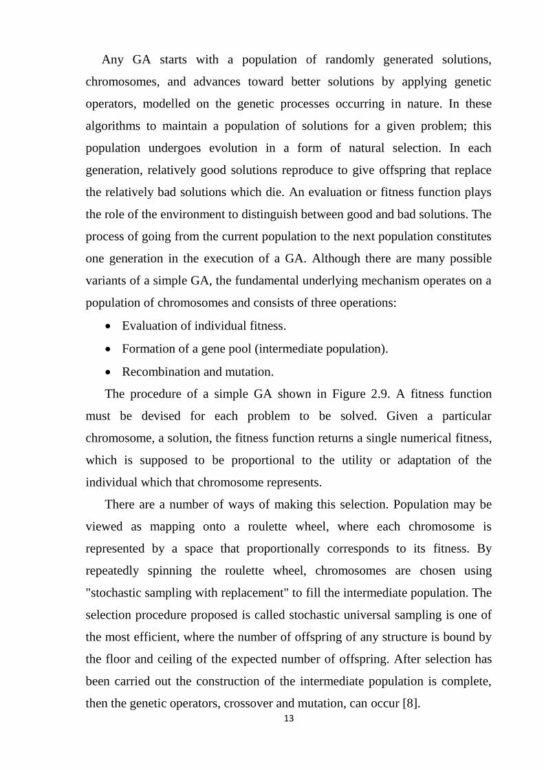
Any GA starts with a population of randomly generated solutions,
chromosomes, and advances toward better solutions by applying genetic
operators, modelled on the genetic processes occurring in nature. In these
algorithms to maintain a population of solutions for a given problem; this
population undergoes evolution in a form of natural selection. In each
generation, relatively good solutions reproduce to give offspring that replace
the relatively bad solutions which die. An evaluation or fitness function plays
the role of the environment to distinguish between good and bad solutions. The
process of going from the current population to the next population constitutes
one generation in the execution of a GA. Although there are many possible
variants of a simple GA, the fundamental underlying mechanism operates on a
population of chromosomes and consists of three operations:
• Evaluation of individual fitness.
• Formation of a gene pool (intermediate population).
• Recombination and mutation.
The procedure of a simple GA shown in Figure 2.9. A fitness function
must be devised for each problem to be solved. Given a particular
chromosome, a solution, the fitness function returns a single numerical fitness,
which is supposed to be proportional to the utility or adaptation of the
individual which that chromosome represents.
There are a number of ways of making this selection. Population may be
viewed as mapping onto a roulette wheel, where each chromosome is
represented by a space that proportionally corresponds to its fitness. By
repeatedly spinning the roulette wheel, chromosomes are chosen using
"stochastic sampling with replacement" to fill the intermediate population. The
selection procedure proposed is called stochastic universal sampling is one of
the most efficient, where the number of offspring of any structure is bound by
the floor and ceiling of the expected number of offspring. After selection has
been carried out the construction of the intermediate population is complete,
then the genetic operators, crossover and mutation, can occur [8].
14
begin (1)
t=0;
initialize P(t);
evaluate P(t);
While (NOT termination-condition) do
begin (2)
t = t + 1
select P(t) from P(T-1)
recombine P(t)
evaluate P(t)
end (2)
end (1)
Figure 2.9: A procedure of simple GA
2.6.1 Basic steps
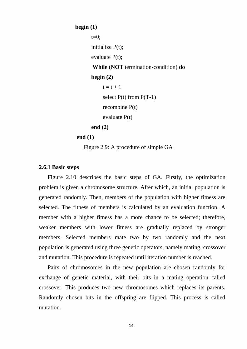
Figure 2.10 describes the basic steps of GA. Firstly, the optimization
problem is given a chromosome structure. After which, an initial population is
generated randomly. Then, members of the population with higher fitness are
selected. The fitness of members is calculated by an evaluation function. A
member with a higher fitness has a more chance to be selected; therefore,
weaker members with lower fitness are gradually replaced by stronger
members. Selected members mate two by two randomly and the next
population is generated using three genetic operators, namely mating, crossover
and mutation. This procedure is repeated until iteration number is reached.
Pairs of chromosomes in the new population are chosen randomly for
exchange of genetic material, with their bits in a mating operation called
crossover. This produces two new chromosomes which replaces its parents.
Randomly chosen bits in the offspring are flipped. This process is called
mutation.
15
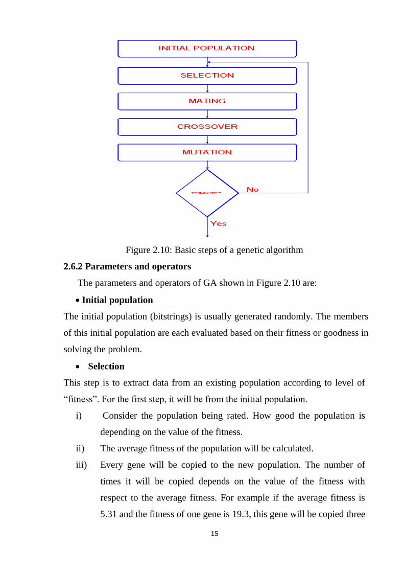
Figure 2.10: Basic steps of a genetic algorithm
2.6.2 Parameters and operators
The parameters and operators of GA shown in Figure 2.10 are:
• Initial population
The initial population (bitstrings) is usually generated randomly. The members
of this initial population are each evaluated based on their fitness or goodness in
solving the problem.
• Selection
This step is to extract data from an existing population according to level of
“fitness”. For the first step, it will be from the initial population.
i) Consider the population being rated. How good the population is
depending on the value of the fitness.
ii) The average fitness of the population will be calculated.
iii) Every gene will be copied to the new population. The number of
times it will be copied depends on the value of the fitness with
respect to the average fitness. For example if the average fitness is
5.31 and the fitness of one gene is 19.3, this gene will be copied three

16
times. Only genes with fitness at the average and above will be
copied. Those with fitness lower than the average will be removed.
iv) Following steps i) to iii), one can prove that in most cases the new
population will be a little smaller than the previous population.
Hence the new population will be filled up with randomly chosen
genes from the old population.
• Mating/crossover
The next steps in generating a new population are mating and crossover. One
type of mating/crossover is the random mating with a defined probability and
the b_nX crossover type.
i) PM percent of each gene of the new population will be selected randomly
and mated in pairs.
ii) A crossover point shown in Figure 2.11 will be chosen for each pair.
iii) The information after the crossover-point will be exchanged between the
two genes of each pair.
However, a slightly different algorithm called b_uX is used more often. This
crossover type usually offers greater performance in the search.
i) PM percent of each gene of the new population will be selected randomly
and mated in pairs.
ii) With the probability PC, also known as crossover rate, two bits in the
same position will be exchanged between the two genes. Thus, more
than one crossover point is chosen. Each bit has a certain probability to
get exchanged with its counterpart in the other gene.
• Mutation
Mutation is a random alteration of a gene in a chromosome. In GA, mutation
includes selecting a random point in the chromosome and replacing the value
found at that point with a suitable value that had been generated randomly as
shown in Figure 2.12. The main purpose of mutation is to ensure diversity in
the population and avoid allele loss. The rate of allele loss is inversely
proportional to the mutation rate of a genetic system [9].

17
Figure 2.11: Crossover
Figure 2.12: Mutation
2.7 DC Motor
The electric motor uses an electrical energy to produce a mechanical
energy. The principles of electrical energy into mechanical energy by
electromagnetic means was demonstrated by the British scientist Michael
Faraday and consisted of a free hanging wire dipping into a pool of mercury. A
permanent magnet was placed in the middle of the pool of mercury. When a
current passé through the wire, the wire rotated around the magnet, showing
that the current gave rise to a circular magnetic field around the wire.
A number of types of electric motors exist, but most BEAM-bots use DC
motors in some form or another. DC motors have the potential for very high
torque capabilities (although this is generally a function of the physical size of
the motor), are easy to miniaturize, and can be "throttled" via adjusting their
supply voltage. DC motors are also not only the simplest, but the oldest
electric motors. The classic DC motor design generates an oscillating current

18
in a wound rotor with a split ring commutator or permanent magnet stator. A
rotor consists of a coil wound around a rotor which is then powered by any
type of battery [10].

19
CHAPTER THREE
CONTROL SYSTEM DESIGN
3.1 Mathematical Modelling
The goal in the development of the mathematical model is to relate the
voltage applied to the armature to the velocity of the motor. Figure 3.1 shows a
separately excited DC motor equivalent model [11]. Note that the various
annotations in the Figure 3.1 are defined as follows:
Va is the armature voltage (Volts).
Eb is back emf the motor (Volts).
Ia is the armature current (Ampere).
Ra is the armature resistance (Ohm).
La is the armature inductance (Henry).
Tm is the mechanical torque developed (Nm).
Jm is moment of inertia (Kgm²).
Bm is friction coefficient of the motor (Nms/rad).
ω is angular velocity (rad/sec).
Figure 3.1: DC motor model
The equations describing the dynamic behavior of the DC motor are given
by the following equations:

20
The armature voltage equation is given by:
Va(t) = Eb(t)+ Ra Ia(t) +La (dIa(t)
dt) (3.1)
The torque balance equation will be given by:
Tm(t) = Jm(dω(t)
dt)+Bmω(t) (3.2)
Friction in rotor of motor is very small (can be neglected), so Bm = 0.
Therefore, new torque balance equation will be given by:
Tm(t) = Jm(dω(t)
dt) (3.3)
The current drawn by a motor is ultimately determined by the torque
produced by a motor. The generated torque (Tm) is dependent upon the current
(Ia), and factors determined by the materials and internal geometry of the
motor. Since the construction of a finished motor will not change during
operation, a constant of proportionality between the motor current and the
materials geometry dependent factors can be calculated for a given motor. This
constant, the torque constant Kt, describes the torque generated by the motor
for a specific motor current:
Tm(t) = Kt Ia(t) (3.4)
Once again, there is a constant of proportionality which describes the
relationship between coil rotational speed (ω) and materials/geometry factors,
commonly known as the back EMF constant (Kb). The back EMF constant is
typically given in volts per unit of rotational speed (which in turn is generally
expressed either in RPM or radians/second).
Eb(t) = Kb ω(t) (3.5)
Let us combine the upper equations together, we have:
21
Va(t) = Kb ω(t)+ Ra Ia(t) +La (dIa(t)
dt) (3.6)
Kt Ia(t) = Jm(dω(t)
dt) (3.7)
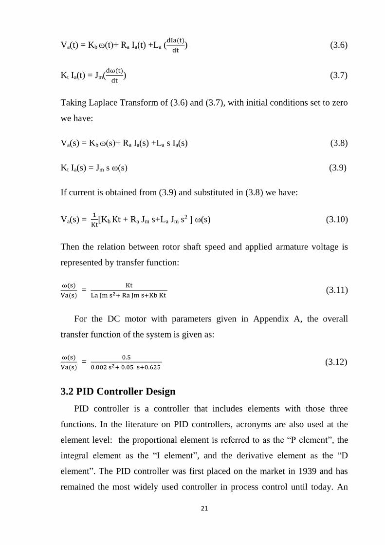
Taking Laplace Transform of (3.6) and (3.7), with initial conditions set to zero
we have:
Va(s) = Kb ω(s)+ Ra Ia(s) +La s Ia(s) (3.8)
Kt Ia(s) = Jm s ω(s) (3.9)
If current is obtained from (3.9) and substituted in (3.8) we have:
Va(s) = 1
Kt[Kb Kt + Ra Jm s+La Jm s2 ] ω(s) (3.10)
Then the relation between rotor shaft speed and applied armature voltage is
represented by transfer function:
ω(s)
Va(s) =
Kt
La Jm s2+ Ra Jm s+Kb Kt (3.11)
For the DC motor with parameters given in Appendix A, the overall
transfer function of the system is given as:
ω(s)
Va(s) =
0.5
0.002 s2+ 0.05 s+0.625 (3.12)
3.2 PID Controller Design
PID controller is a controller that includes elements with those three
functions. In the literature on PID controllers, acronyms are also used at the
element level: the proportional element is referred to as the “P element”, the
integral element as the “I element”, and the derivative element as the “D
element”. The PID controller was first placed on the market in 1939 and has
remained the most widely used controller in process control until today. An

22
investigation performed in 1989 in Japan indicated that more than 90% of the
controllers used in process industries are PID controllers and advanced
versions of the PID controller.
PID control is the method of feedback control that uses the PID controller
as the main tool. Figure 3.2 shows the schematic model of a control system
with a PID controller. In this figure, the process is the object to be controlled.
The purpose of control is to make the process variable y(t) follow the set-point
value r(t). To achieve this purpose, the manipulated variable u(t) is changed at
the command of the controller. As an example of processes, consider a heating
tank in which some liquid is heated to a desired temperature by burning fuel
gas. The process variable y(t) is the temperature of the liquid, and the
manipulated variable u(t) is the flow of the fuel gas. The error e(t) is defined
by e(t)=r(t) –y(t). The last thing to notice about Figure 3.2 is that the process
variable y(t) is assumed to be measured by the detector, which is not shown
explicitly here, with sufficient accuracy instantaneously that the input to the
controller can be regarded as being exactly equal to y(t). Control signal u(t) is
a linear combination of error e(t), its integral and derivative.
u(t)=kPe(t)+ ki ∫ e(t)dt+kd de(t)
dt (3.13)
where kP is the proportional gain, kd is the differential gain, and ki is the
integral gain.
.
Figure 3.2: Conventional feedback control system

23
In applying PID controllers, engineers must design the control system. In
other words, they must first decide which element(s) to keep in action and then
adjust the parameters so that their control problems are solved appropriately.
To that end, they need to know the characteristics of the process. As the basis
for this design procedure, they must have certain criteria to evaluate the
performance of the control system [12].
The process of controlling the DC motor using a PID controller starts by
achieving the error input. The error input is the difference between the output
from the system, and the output of step source. And then the two outputs were
compared using a sum point. Then this error is connected to the PID controller,
and the PID controller is fed to the subsystem.
Since the speed of the DC motor is the variable under control, any change
in the speed will produce an error signal which will reach the PID controller,
indicating a change in speed. Then the PID controller will work trying to
maintain the speed of the DC motor. Then after connecting the output to a
display “scope” to view the result (the output of the DC motor). Figure 3.3
shows the PID control system designed in MATLAB/SIMULINK where
controller parameters are adjusted using Ziegler-Nichols method.
Figure 3.3:MATLAB/SIMULINK model of system using PID controller
3.3 Fuzzy Controller Design
Now after controlling the DC motor using a PID controller, the DC motor
is controlled using a FLC. Following the same procedure used for the PID
controller, the PID is replaced with a fuzzy logic controller as shown in Figure
24
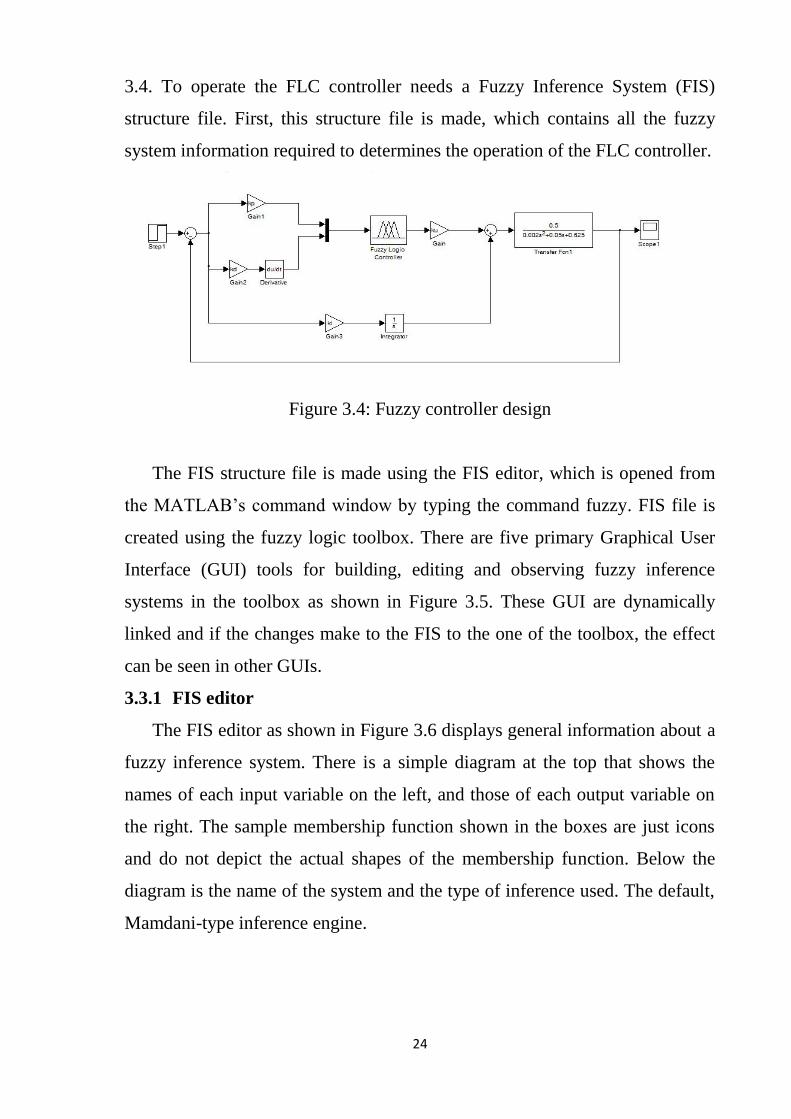
3.4. To operate the FLC controller needs a Fuzzy Inference System (FIS)
structure file. First, this structure file is made, which contains all the fuzzy
system information required to determines the operation of the FLC controller.
Figure 3.4: Fuzzy controller design
The FIS structure file is made using the FIS editor, which is opened from
the MATLAB’s command window by typing the command fuzzy. FIS file is
created using the fuzzy logic toolbox. There are five primary Graphical User
Interface (GUI) tools for building, editing and observing fuzzy inference
systems in the toolbox as shown in Figure 3.5. These GUI are dynamically
linked and if the changes make to the FIS to the one of the toolbox, the effect
can be seen in other GUIs.
3.3.1 FIS editor
The FIS editor as shown in Figure 3.6 displays general information about a
fuzzy inference system. There is a simple diagram at the top that shows the
names of each input variable on the left, and those of each output variable on
the right. The sample membership function shown in the boxes are just icons
and do not depict the actual shapes of the membership function. Below the
diagram is the name of the system and the type of inference used. The default,
Mamdani-type inference engine.

25
Figure 3.5: Fuzzy inference system
Figure 3.6: FIS editor
26
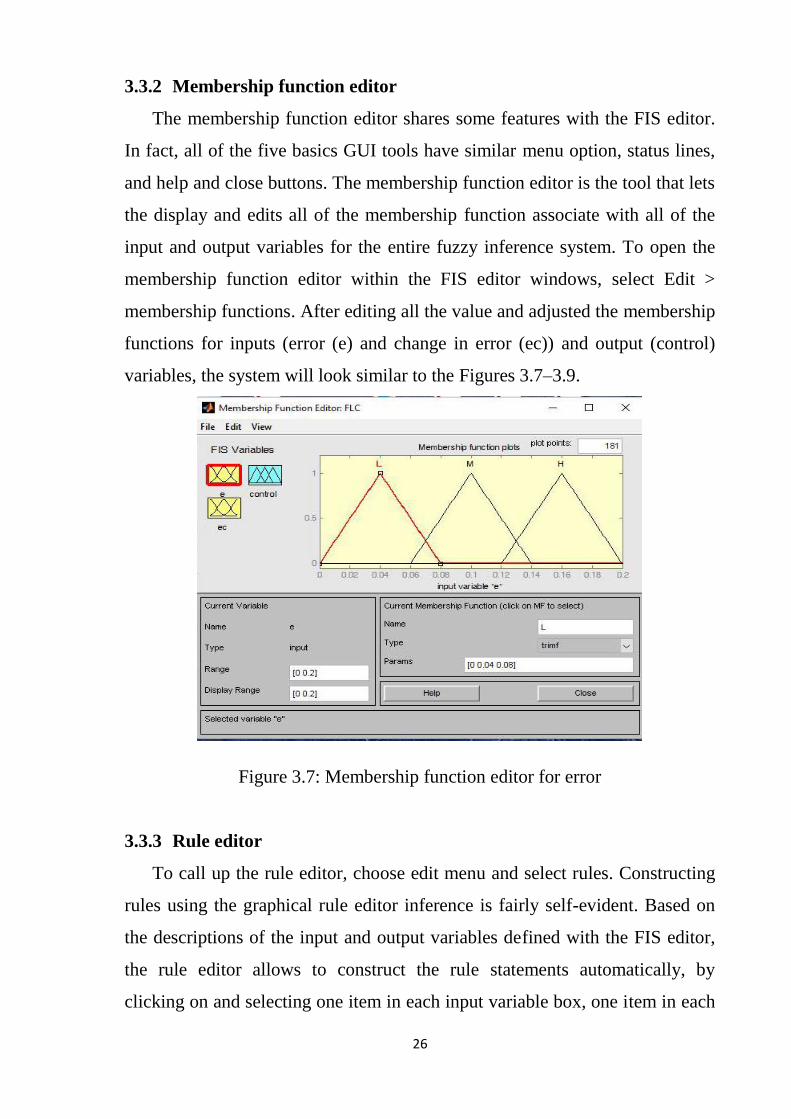
3.3.2 Membership function editor
The membership function editor shares some features with the FIS editor.
In fact, all of the five basics GUI tools have similar menu option, status lines,
and help and close buttons. The membership function editor is the tool that lets
the display and edits all of the membership function associate with all of the
input and output variables for the entire fuzzy inference system. To open the
membership function editor within the FIS editor windows, select Edit >
membership functions. After editing all the value and adjusted the membership
functions for inputs (error (e) and change in error (ec)) and output (control)
variables, the system will look similar to the Figures 3.7–3.9.
Figure 3.7: Membership function editor for error
3.3.3 Rule editor
To call up the rule editor, choose edit menu and select rules. Constructing
rules using the graphical rule editor inference is fairly self-evident. Based on
the descriptions of the input and output variables defined with the FIS editor,
the rule editor allows to construct the rule statements automatically, by
clicking on and selecting one item in each input variable box, one item in each

27
output box, and one connection item. Choosing none as one of the variable
qualities will exclude that variable from a given rule. Choosing not under any
variable name will negate the associated quality. Rules may be changed,
deleted, or added, by clicking on the appropriate button. The rule editor also
has some familiar landmarks, similar to those in the FIS editor and the
membership function editor, including the menu bar and the status line. The
format pop-up menu is available from the option pull-down menu from the top
menu bar this is used to set the format for display. The set of linguistic rules is
the essential part of a fuzzy controller. The various linguistic variables to
design rule base for output of the FLC are enlisted in Table 3.1.
Table 3.1: Fuzzy rules
e ec L M H
L L M M
M L M H
H M M H
Figure 3.8: Membership function editor for change in error
28
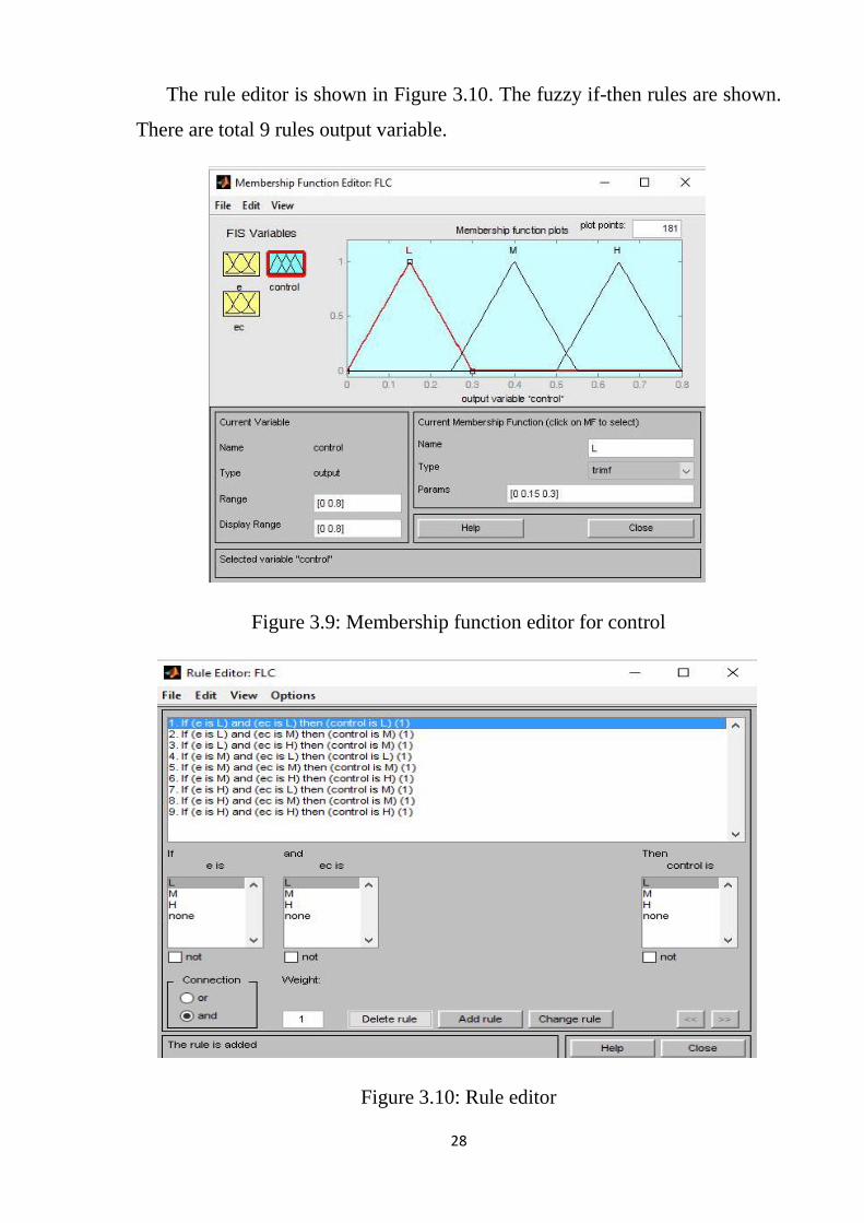
The rule editor is shown in Figure 3.10. The fuzzy if-then rules are shown.
There are total 9 rules output variable.
Figure 3.9: Membership function editor for control
Figure 3.10: Rule editor

29
3.3.4 Rule viewer
The rule viewer as shown in Figure 3.11 displays a road map of the whole
fuzzy inference process. It is based on the fuzzy inference diagram described
in the previous section. The three plots across the top of the Figure 3.11
represent the antecedent and consequent of the first rule. Each rule is a row of
plots, and each column is a variable. The rule numbers are displayed on the left
of each row. To view the rule in the status line click the rule number.
Figure 3.11: Rule viewer
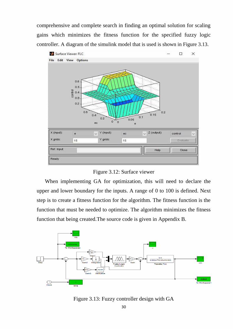
3.3.5 Surface viewer
This is the last of five basic GUI tools in the fuzzy logic toolbox, and
opening it by selecting View surface... from the view menu. then the output of
an FIS generates a 3-D surface from two input variables The surface viewer is
shown in Figure 3.12.
3.4 Fuzzy Controller Design With GA
The fuzzy controller for a motor speed is re-implemented but the only
difference this time is that is optimized. The GA is employed to perform a
30
comprehensive and complete search in finding an optimal solution for scaling
gains which minimizes the fitness function for the specified fuzzy logic
controller. A diagram of the simulink model that is used is shown in Figure 3.13.
Figure 3.12: Surface viewer
When implementing GA for optimization, this will need to declare the
upper and lower boundary for the inputs. A range of 0 to 100 is defined. Next
step is to create a fitness function for the algorithm. The fitness function is the
function that must be needed to optimize. The algorithm minimizes the fitness
function that being created.The source code is given in Appendix B.
Figure 3.13: Fuzzy controller design with GA
31
CHAPTER FOUR
SIMULATION RESULTS
4.1 Introduction
Simulation results of uncontrolled speed response of the system and
response of the system with PID controller, FLC and FLC with GA are
obtained using MATLAB/SIMULINK.
4.2 Simulation Results for Uncontrolled DC Motor
The response of the uncontrolled DC motor to a unit step input is shown in
Figure 4.1.
Figure 4.1: Uncontrolled speed response of the system
4.3 Simulation Results With PID Controller
The control signal of controller is shown in Figure 4.2 and the unit step
response of the speed of the DC motor with the PID controller is shown in
Figure 4.3. According to Ziegler—Nichols made the PID control parameters
derived from the formula are: kp = 6, ki = 120 and Kd = 0.075. Running the
simulation process for the system when using PID controller the resulting

32
characteristic values are: rise time (Tr)= 0.0458 seconds, Settling time (Ts) =
0.21seconds and Maximum Overshoot (MP)=40.8%.
Figure 4.2: Control signal of PID controller
Figure 4.3: Speed response of the system with PID controller
As can be seen from Figure 4.3 the PID controlled response of the system
has considerably high overshoot . Hence, an attempt is made to further
improve the response of the system using fuzzy logic controller.
33
4.4 Simulation Results With FLC Controller
The control signal of controller is shown in Figure 4.4 and the response of
the system with FLC is shown in Figure 4.5.
Figure 4.4: Control signal of FLC
Figure 4.5: Speed response of the system with FLC
Running the simulation process for the system when using FLC controller,
the resulting characteristic values are: Tr=0.14 seconds, Ts= 0.6 seconds and
MP= 19%. Figure 4.5 shows the system output response after considerable
34
hand tuning of FLC, when compared to the PID using classic ZN method the
fuzzy logic controller shows a better performance in terms of overshoot while
it exhibits a slightly lesser performance in terms of rise time and settling time.
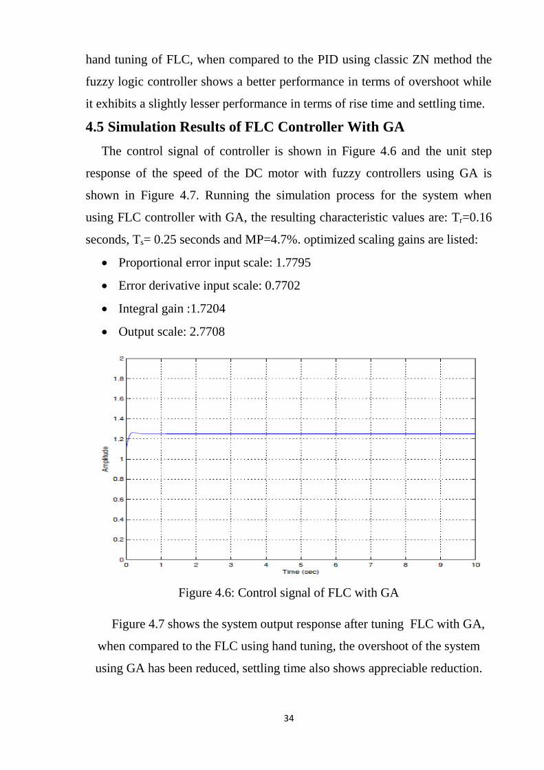
4.5 Simulation Results of FLC Controller With GA
The control signal of controller is shown in Figure 4.6 and the unit step
response of the speed of the DC motor with fuzzy controllers using GA is
shown in Figure 4.7. Running the simulation process for the system when
using FLC controller with GA, the resulting characteristic values are: Tr=0.16
seconds, Ts= 0.25 seconds and MP=4.7%. optimized scaling gains are listed:
• Proportional error input scale: 1.7795
• Error derivative input scale: 0.7702
• Integral gain :1.7204
• Output scale: 2.7708
Figure 4.6: Control signal of FLC with GA
Figure 4.7 shows the system output response after tuning FLC with GA,
when compared to the FLC using hand tuning, the overshoot of the system
using GA has been reduced, settling time also shows appreciable reduction.

35
Figure 4.7: Speed response of the system with fuzzy controller using GA
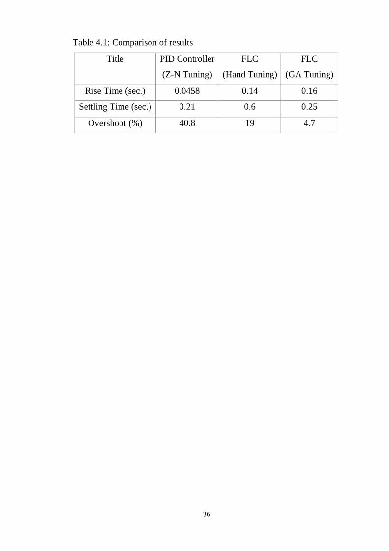
4.6 Results Comparison
A comparison of the step response is shown in Figure 4.8. The
performance metrics obtained from different tuning methods are also shown in
the Table 4.1.
Figure 4.8: Comparative responses
36
Table 4.1: Comparison of results
Title PID Controller
(Z-N Tuning)
FLC
(Hand Tuning)
FLC
(GA Tuning)
Rise Time (sec.) 0.0458 0.14 0.16
Settling Time (sec.) 0.21 0.6 0.25
Overshoot (%) 40.8 19 4.7
37
CHAPTER FIVE
CONCLUSION AND RECOMMENDATIONS
5.1 Conclusion
This study has succeeded in the design of an optimal fuzzy logic controller
using genetic algorithm technique. MATLAB/SIMULINK is used to simulate
and fine-tune the controller models. the proper optimized gain values of
controller are obtained with GA. By comparing the results of the performance
metrics in Table 4.1, it can be noted that the GA-optimized fuzzy logic
controller produces better more desirable performance compared with other
controllers. The simulation results show that the optimal fuzzy logic controller
is functioning better than other in term of the overshoot.
5.2 Recommendations
At the end of this study many points could be taken as suggested future
works:
• Use other types of membership functions.
• Use graphical user interface for GA.
• Hardware implementation in order to further analyze and verify the
performance of the optimal fuzzy logic controller.
38
REFERENCES
[1] Chen Guo, Zhen Ye, Zengqi Sun, Purnendu Sarkar, Mo Jamshidi, "A
hybrid fuzzy cerebellar model articulation controller based autonomous
controller", Journal Computer and Electrical Engineering, 2002.
[2] Katsuhiko Ogata , "Modern Control Engineering", Pearson, 2009.
[3] Earl Cox,” Fuzzy Fundamentals", IEEE SPECTRUM, 1992.
[4] Jan Jantzen, ''Design of Fuzzy Controllers'', Technical University of
Denmark, 1998.
[5] Rashmi Garde Phalnikar, Nisha V. Kimmatkar, Suhas Patil and SHashank
Joshi, "Fuzzy logic and its use in control engineering", Allied Publishers,
2005.
[6] Van Leekwijck and Kerre, ''Defuzzification: criteria and classification'',
Journal Fuzzy Sets and Systems, 1999.
[7] M. Tim Jones. "AI Application Programming", Charles River Media, 2005.
[8] Beasley D, Bull D and Martin R, "An Overview of Genetic Algorithms",
university computing, 1994.
[9] Peter Hackett, "A Comparison of Selection Methods Based on the
Performance of a Genetic Program Applied to the Cart-pole Problem". Griffith
University, 1995.
[10] B.L. Theraja "A Textbook Of Electrical Technology", Chand (S.) & Co
Ltd ,India, 2008.
[11] Chi-Tsong Chen, "Analog and Digital Control System Design", Oxford
University Press, 2006.
[12] Norman S.Nise, "Control Systems Engineering", Wiley, 2012.

39
APPENDICES
APPENDIX A: SYSTEM MODEL PARAMETERS
Armature resistance (Ra) 0.5Ω
Armature inductance (La) 0.02 H
Armature voltage (Va) 200 V
Mechanical inertia (jm) 0.1 Kg.m2
Friction coefficient (Bm) 0.008 Nms/rad
Back emf constant (k) 1.25 V/rad/sec
Motor torque constant (k) 0.5 N.m/A
40
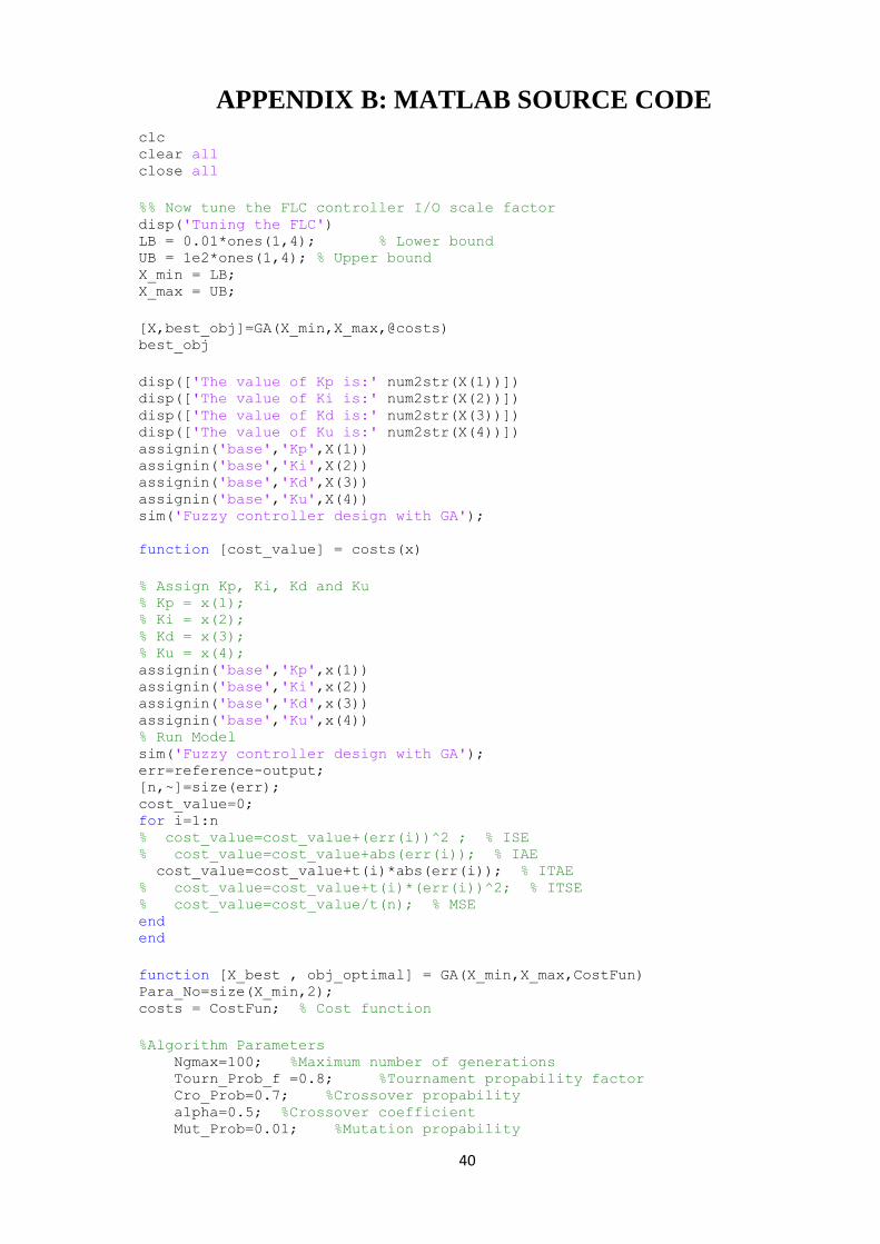
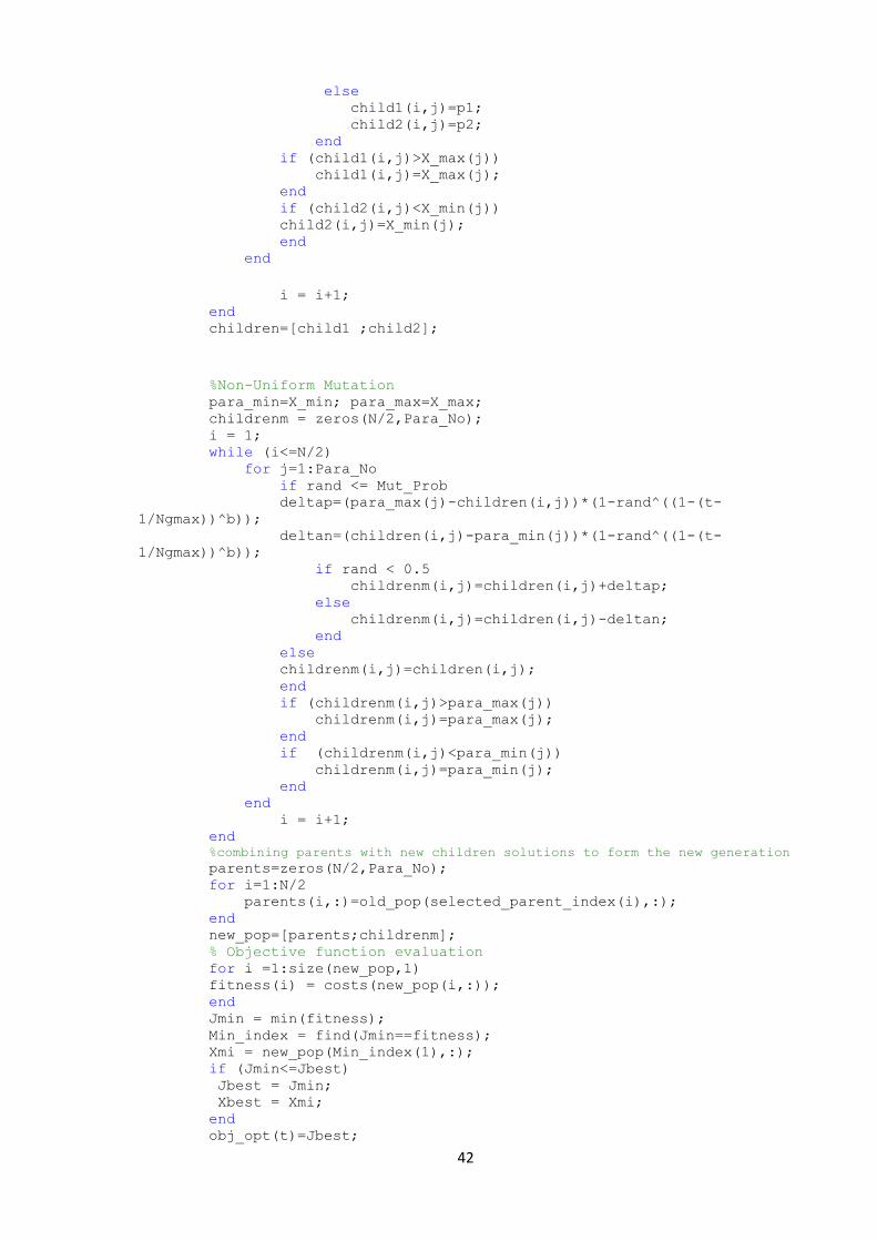
APPENDIX B: MATLAB SOURCE CODE
clc clear all close all
%% Now tune the FLC controller I/O scale factor disp('Tuning the FLC') LB = 0.01*ones(1,4); % Lower bound UB = 1e2*ones(1,4); % Upper bound X_min = LB; X_max = UB;
[X,best_obj]=GA(X_min,X_max,@costs) best_obj
disp(['The value of Kp is:' num2str(X(1))]) disp(['The value of Ki is:' num2str(X(2))]) disp(['The value of Kd is:' num2str(X(3))]) disp(['The value of Ku is:' num2str(X(4))]) assignin('base','Kp',X(1)) assignin('base','Ki',X(2)) assignin('base','Kd',X(3)) assignin('base','Ku',X(4)) sim('Fuzzy controller design with GA');
function [cost_value] = costs(x)
% Assign Kp, Ki, Kd and Ku % Kp = x(1); % Ki = x(2); % Kd = x(3); % Ku = x(4); assignin('base','Kp',x(1)) assignin('base','Ki',x(2)) assignin('base','Kd',x(3))
assignin('base','Ku',x(4)) % Run Model sim('Fuzzy controller design with GA'); err=reference-output; [n,~]=size(err); cost_value=0; for i=1:n % cost_value=cost_value+(err(i))^2 ; % ISE % cost_value=cost_value+abs(err(i)); % IAE cost_value=cost_value+t(i)*abs(err(i)); % ITAE % cost_value=cost_value+t(i)*(err(i))^2; % ITSE % cost_value=cost_value/t(n); % MSE end end
function [X_best , obj_optimal] = GA(X_min,X_max,CostFun) Para_No=size(X_min,2); costs = CostFun; % Cost function
%Algorithm Parameters Ngmax=100; %Maximum number of generations Tourn_Prob_f =0.8; %Tournament propability factor Cro_Prob=0.7; %Crossover propability alpha=0.5; %Crossover coefficient Mut_Prob=0.01; %Mutation propability
41
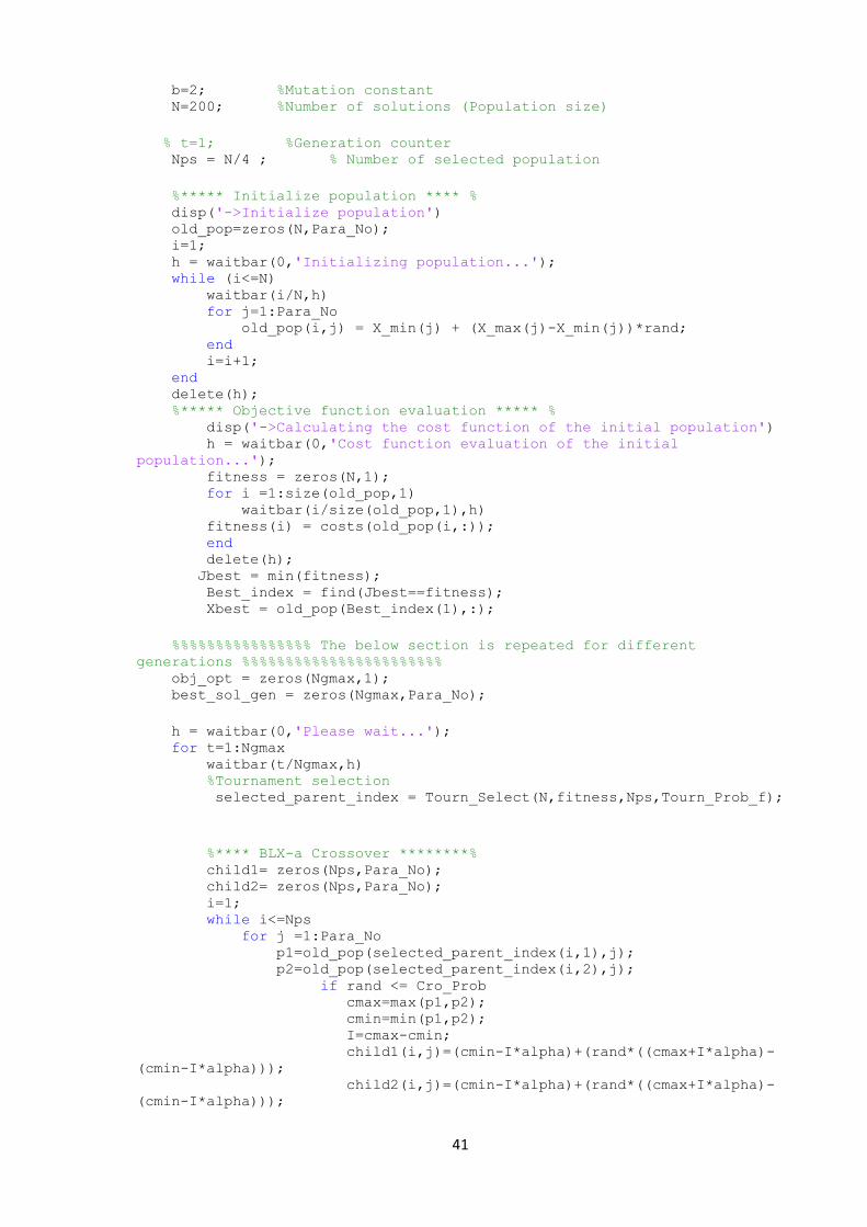
b=2; %Mutation constant N=200; %Number of solutions (Population size)
% t=1; %Generation counter Nps = N/4 ; % Number of selected population
%***** Initialize population **** % disp('->Initialize population') old_pop=zeros(N,Para_No); i=1; h = waitbar(0,'Initializing population...'); while (i<=N) waitbar(i/N,h) for j=1:Para_No old_pop(i,j) = X_min(j) + (X_max(j)-X_min(j))*rand; end i=i+1; end delete(h); %***** Objective function evaluation ***** % disp('->Calculating the cost function of the initial population') h = waitbar(0,'Cost function evaluation of the initial
population...'); fitness = zeros(N,1); for i =1:size(old_pop,1) waitbar(i/size(old_pop,1),h) fitness(i) = costs(old_pop(i,:)); end delete(h); Jbest = min(fitness); Best_index = find(Jbest==fitness); Xbest = old_pop(Best_index(1),:);
%%%%%%%%%%%%%%%% The below section is repeated for different
generations %%%%%%%%%%%%%%%%%%%%%%% obj_opt = zeros(Ngmax,1); best_sol_gen = zeros(Ngmax,Para_No);
h = waitbar(0,'Please wait...'); for t=1:Ngmax waitbar(t/Ngmax,h) %Tournament selection selected_parent_index = Tourn_Select(N,fitness,Nps,Tourn_Prob_f);
%**** BLX-a Crossover ********% child1= zeros(Nps,Para_No); child2= zeros(Nps,Para_No); i=1; while i<=Nps for j =1:Para_No p1=old_pop(selected_parent_index(i,1),j); p2=old_pop(selected_parent_index(i,2),j); if rand <= Cro_Prob cmax=max(p1,p2); cmin=min(p1,p2); I=cmax-cmin; child1(i,j)=(cmin-I*alpha)+(rand*((cmax+I*alpha)-
(cmin-I*alpha))); child2(i,j)=(cmin-I*alpha)+(rand*((cmax+I*alpha)-
(cmin-I*alpha)));
42
else child1(i,j)=p1; child2(i,j)=p2; end if (child1(i,j)>X_max(j)) child1(i,j)=X_max(j); end if (child2(i,j)<X_min(j)) child2(i,j)=X_min(j); end end
i = i+1; end children=[child1 ;child2];
%Non-Uniform Mutation para_min=X_min; para_max=X_max; childrenm = zeros(N/2,Para_No); i = 1; while (i<=N/2) for j=1:Para_No if rand <= Mut_Prob deltap=(para_max(j)-children(i,j))*(1-rand^((1-(t-
1/Ngmax))^b)); deltan=(children(i,j)-para_min(j))*(1-rand^((1-(t-
1/Ngmax))^b)); if rand < 0.5 childrenm(i,j)=children(i,j)+deltap; else childrenm(i,j)=children(i,j)-deltan; end else childrenm(i,j)=children(i,j); end if (childrenm(i,j)>para_max(j)) childrenm(i,j)=para_max(j); end if (childrenm(i,j)<para_min(j)) childrenm(i,j)=para_min(j); end end i = i+1; end %combining parents with new children solutions to form the new generation
parents=zeros(N/2,Para_No); for i=1:N/2 parents(i,:)=old_pop(selected_parent_index(i),:); end new_pop=[parents;childrenm]; % Objective function evaluation for i =1:size(new_pop,1) fitness(i) = costs(new_pop(i,:)); end Jmin = min(fitness); Min_index = find(Jmin==fitness); Xmi = new_pop(Min_index(1),:); if (Jmin<=Jbest) Jbest = Jmin; Xbest = Xmi; end obj_opt(t)=Jbest;

43
%best_sol_index=find(fitness==obj_opt(t)); best_sol_gen(t,:)=Xbest; old_pop=new_pop; end delete(h); obj_optm = obj_opt;
obj_optimal=min(obj_optm); op_sol_index=find(obj_optm==obj_optimal); X_best=best_sol_gen(op_sol_index(1),:);
return
% This function is responsible for the tournament selection operation it % receives the following arguments: % The number of solution (population) (N) % The fitness value of each solution (fitness) % The number of selected solution (Nps) % The tournament selection probability (Tourn_Prob_f) % Then it produces the selected parant index (Selected_Parent_index)
function Selected_Parent_index = Tourn_Select(N,fitness,Nps,Tourn_Prob_f) Selected_Parent_index=zeros(Nps,2); for i=1:Nps ti1=randi([1 N],1); %Random Tournament index 1 ti2=randi([1 N],1); %Random Tournament index 2 if rand <= Tourn_Prob_f if fitness(ti1)<fitness(ti2) pi1=ti1; %Parent index 1 else pi1=ti2; end else if fitness(ti1)<fitness(ti2) pi1=ti2; else pi1=ti1; end end
ti1=randi([1 N],1); %Random Tournament index 1 ti2=randi([1 N],1); %Random Tournament index 2 if rand()<= Tourn_Prob_f if fitness(ti1)<fitness(ti2) pi2=ti1; %Parent index 2 else pi2=ti2; end else if fitness(ti1)<fitness(ti2) pi2=ti2; else pi2=ti1; end end Selected_Parent_index(i,:)=[pi1 pi2]; %Parent index vector end return
Related Documents