Experimental access to higher-order Zeeman effects by precision spectroscopy of highly charged ions in a Penning trap D. von Lindenfels GSI Helmholtzzentrum f¨ ur Schwerionenforschung, Planckstrasse 1, 64291 Darmstadt, Germany and Max-Planck-Institut f¨ ur Kernphysik, Saupfercheckweg 1, 69117 Heidelberg, Germany M. Wiesel Institut f¨ ur Angewandte Physik, Technische Universit¨ at Darmstadt, 64289 Darmstadt, Germany and Physikalisches Institut, Im Neuenheimer Feld 226, 69120 Heidelberg, Germany D. A. Glazov and A. V. Volotka Department of Physics, St. Petersburg State University, Oulianovskaya 1, Petrodvorets, 198504 St. Petersburg, Russia and Institut f¨ ur Theoretische Physik, Technische Universit¨ at Dresden, Mommsenstraße 13, 01062 Dresden, Germany M. M. Sokolov and V. M. Shabaev Department of Physics, St. Petersburg State University, Oulianovskaya 1, Petrodvorets, 198504 St. Petersburg, Russia G. Plunien Institut f¨ ur Theoretische Physik, Technische Universit¨ at Dresden, Mommsenstraße 13, 01062 Dresden, Germany W. Quint GSI Helmholtzzentrum f¨ ur Schwerionenforschung, Planckstrasse 1, 64291 Darmstadt, Germany and Physikalisches Institut, Im Neuenheimer Feld 226, 69120 Heidelberg, Germany G. Birkl, A. Martin, and M. Vogel * Institut f¨ ur Angewandte Physik, Technische Universit¨ at Darmstadt, 64289 Darmstadt, Germany We present an experimental concept and setup for laser-microwave double-resonance spectroscopy of highly charged ions in a Penning trap. Such spectroscopy allows a highly precise measurement of the Zeeman splittings of fine- and hyperfine-structure levels due the magnetic field of the trap. We have performed detailed calculations of the Zeeman effect in the framework of quantum electrody- namics of bound states as present in such highly charged ions. We find that apart from the linear Zeeman effect, second- and third-order Zeeman effects also contribute to the splittings on a level of 10 -4 and 10 -8 , respectively, and hence are accessible to a determination within the achievable spectroscopic resolution of the ARTEMIS experiment currently in preparation. PACS numbers: 32.60.+i, 42.62.Fi, 78.70.Gq, 37.10.Ty I. INTRODUCTION Ever since the discovery of a quadratic contribution to the Zeeman effect by Jenkins and Segr´ e in the 1930s [1, 2], there have been numerous studies both experi- mental and theoretical of higher-order Zeeman contri- butions in atoms, molecules, and singly charged ions in laboratory magnetic fields (see, for example, [3–6]). The high magnetic field strengths present in astro- nomical objects have given impetus to corresponding studies in observational astronomy [7–11], identifying * [email protected] a quadratic Zeeman effect in abundant species like hy- drogen and helium. Although highly charged ions are both abundant in the universe and readily accessible in laboratories, to our knowledge, no higher-order Zee- man effect in highly charged ions has been observed so far. In highly charged ions of a given charge state, the electronic energy level splittings depend strongly on the nuclear charge Z . For one-electron ions (i.e., hy- drogenlike ions) the energy splitting is proportional to Z 2 for principal transitions, to Z 3 for hyperfine- structure transitions, and to Z 4 for fine-structure transitions. In other few-electron ions the scaling is very similar [12, 13]. Since in the hydrogen atom prin- cipal transitions are typically at a few eV, the scaling arXiv:1306.1393v1 [physics.atom-ph] 6 Jun 2013

Welcome message from author
This document is posted to help you gain knowledge. Please leave a comment to let me know what you think about it! Share it to your friends and learn new things together.
Transcript
Experimental access to higher-order Zeeman effectsby precision spectroscopy of highly charged ions in a Penning trap
D. von LindenfelsGSI Helmholtzzentrum fur Schwerionenforschung,Planckstrasse 1, 64291 Darmstadt, Germany and
Max-Planck-Institut fur Kernphysik, Saupfercheckweg 1, 69117 Heidelberg, Germany
M. WieselInstitut fur Angewandte Physik, Technische Universitat Darmstadt, 64289 Darmstadt, Germany and
Physikalisches Institut, Im Neuenheimer Feld 226, 69120 Heidelberg, Germany
D. A. Glazov and A. V. VolotkaDepartment of Physics, St. Petersburg State University,
Oulianovskaya 1, Petrodvorets, 198504 St. Petersburg, Russia andInstitut fur Theoretische Physik, Technische Universitat Dresden,
Mommsenstraße 13, 01062 Dresden, Germany
M. M. Sokolov and V. M. ShabaevDepartment of Physics, St. Petersburg State University,
Oulianovskaya 1, Petrodvorets, 198504 St. Petersburg, Russia
G. PlunienInstitut fur Theoretische Physik, Technische Universitat Dresden,
Mommsenstraße 13, 01062 Dresden, Germany
W. QuintGSI Helmholtzzentrum fur Schwerionenforschung,Planckstrasse 1, 64291 Darmstadt, Germany and
Physikalisches Institut, Im Neuenheimer Feld 226, 69120 Heidelberg, Germany
G. Birkl, A. Martin, and M. Vogel∗
Institut fur Angewandte Physik, Technische Universitat Darmstadt, 64289 Darmstadt, Germany
We present an experimental concept and setup for laser-microwave double-resonance spectroscopyof highly charged ions in a Penning trap. Such spectroscopy allows a highly precise measurement ofthe Zeeman splittings of fine- and hyperfine-structure levels due the magnetic field of the trap. Wehave performed detailed calculations of the Zeeman effect in the framework of quantum electrody-namics of bound states as present in such highly charged ions. We find that apart from the linearZeeman effect, second- and third-order Zeeman effects also contribute to the splittings on a levelof 10−4 and 10−8, respectively, and hence are accessible to a determination within the achievablespectroscopic resolution of the ARTEMIS experiment currently in preparation.
PACS numbers: 32.60.+i, 42.62.Fi, 78.70.Gq, 37.10.Ty
I. INTRODUCTION
Ever since the discovery of a quadratic contributionto the Zeeman effect by Jenkins and Segre in the 1930s[1, 2], there have been numerous studies both experi-mental and theoretical of higher-order Zeeman contri-butions in atoms, molecules, and singly charged ionsin laboratory magnetic fields (see, for example, [3–6]).The high magnetic field strengths present in astro-nomical objects have given impetus to correspondingstudies in observational astronomy [7–11], identifying
a quadratic Zeeman effect in abundant species like hy-drogen and helium. Although highly charged ions areboth abundant in the universe and readily accessiblein laboratories, to our knowledge, no higher-order Zee-man effect in highly charged ions has been observedso far.
In highly charged ions of a given charge state, theelectronic energy level splittings depend strongly onthe nuclear charge Z. For one-electron ions (i.e., hy-drogenlike ions) the energy splitting is proportionalto Z2 for principal transitions, to Z3 for hyperfine-structure transitions, and to Z4 for fine-structuretransitions. In other few-electron ions the scaling isvery similar [12, 13]. Since in the hydrogen atom prin-cipal transitions are typically at a few eV, the scaling
arX
iv:1
306.
1393
v1 [
phys
ics.
atom
-ph]
6 J
un 2
013
2
with Z2 shifts these transitions far into the XUV andx-ray regime for heavier hydrogenlike ions, and thusout of the reach of studies like the present one.
In an external magnetic field, the Zeeman effect liftsthe degeneracy of energies within fine- and hyperfine-structure levels. For highly charged ions in magneticfields of a few tesla strength as typical for Penningtrap operation, the corresponding Zeeman splitting iswell within the microwave domain and thus accessi-ble for precision spectroscopy. In addition, in fine-and hyperfine-structure transitions, the strong scal-ing with Z eventually shifts the corresponding ener-gies into the laser-accessible region and thus makesthem available for precision optical spectroscopy [14].
We are currently setting up a laser-microwavedouble-resonance spectroscopy experiment withhighly charged ions in a Penning trap, which com-bines precise spectroscopy of both optical transitionsand microwave Zeeman splittings [15, 16]. The exper-iment aims at spectroscopic precision measurementsof such energy level splittings and magnetic momentsof bound electrons on the ppb level of accuracy andbetter. At the same time, it allows access to thenuclear magnetic moment in the absence of diamag-netic shielding [15, 17]. For first tests within theAsymmetRic Trap for the measurement of ElectronMagnetic moments in IonS (ARTEMIS) experiment,the 40Ar13+ (spectroscopic notation: ArXIV) ion hasbeen chosen. It has a spinless nucleus, such that onlya fine structure is present. Similar measurementsin hyperfine structures are to be performed withions of higher charge states such as, for example,207Pb81+ and 209Bi82+ as available to ARTEMISwithin the framework of the HITRAP facility [18] atGSI, Germany.
We have performed detailed relativistic calculationsof the Zeeman effect in boronlike ions such as Ar13+.These calculations show that at the ppb level of ex-perimental accuracy, higher-order effects play a sig-nificant role and need to be accounted for. In turn,precision spectroscopy of highly charged ions allowsa measurement of these higher-order contributions tothe Zeeman effect.
II. CALCULATION OF THE ZEEMANEFFECT
We consider a five-electron argon ion in theground [(1s)2(2s)22p] 2P1/2 and in the first excited
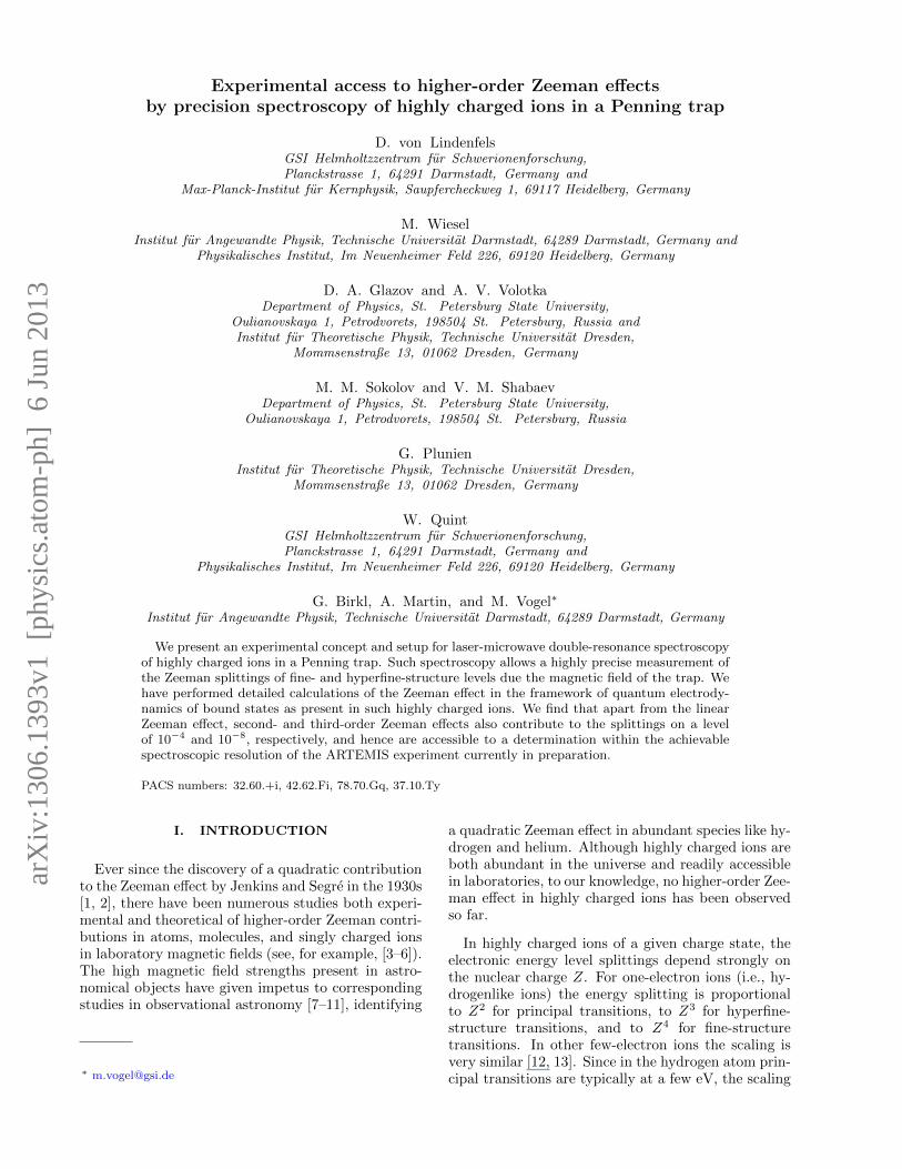
[(1s)2(2s)22p] 2P3/2 states. The fine-structure inter-val between these levels has previously been studied[19–22], as well as the corresponding magnetic dipoletransition rate [23–26]. An external magnetic fieldsplits levels with different angular momentum projec-tion onto the direction of the field. While this split-ting is equidistant in the first-order approximation,the nonlinear magnetic field effects disturb this sym-metry. The corresponding level structure is schemat-
ically depicted in Fig. 1.
FIG. 1. (Color online) Level scheme of the 2 2PJ states ofboronlike argon ArXIV in an external magnetic field withhigher-order contributions to the Zeeman effect (not trueto scale).
The Zeeman shift of each level can be evaluatedwithin perturbation theory,
EA(B) = E(0)A + ∆E
(1)A (B)
+∆E(2)A (B) + ∆E
(3)A (B) + · · · , (1)
where |A〉 = |J,MJ〉 is the 2 2PJ state with total angu-lar momentum J and its projection MJ . In the follow-ing, the quantities which do not depend on MJ (e.g.,
the energy in the absence of magnetic field, E(0)A ) are
labeled with J only. Each term of the perturbation ex-pansion is proportional to the magnetic field strength
to the corresponding power, ∆E(n)A (B) ∼ Bn. The
first-order term is directly related to the gJ factor by
∆E(1)A (B) = gJMJµBB, (2)
where µB is the Bohr magneton. The Dirac equationfor the valence |a〉 = |2p〉 electron is an appropriate
zeroth approximation to find ∆E(1)A (B) as
∆E(1)A (B) = 〈a|Vm|a〉, (3)
where the operator
Vm =|e|2
[r×α] ·B (4)
represents the interaction with the external homoge-neous magnetic field B. For the Coulomb potential ofa pointlike nucleus, one finds
g1/2 =2
3
[√2[1 +
√1− (αZ)2
]− 1
]
=2
3− 1
6(αZ)2 − 5
96(αZ)4 − · · · , (5)
g3/2 =4
15
[2√
4− (αZ)2 + 1]
=4
3− 2
15(αZ)2 − 1
120(αZ)4 − · · · . (6)

3
The interelectronic interaction, quantum electrody-namical, and nuclear effects give rise to corrections tothese values. Evaluation of the gJ factors of the 2 2P1/2
and 2 2P3/2 states of boronlike argon in Ref. [21]yielded g1/2 = 0.663 65 and g3/2 = 1.332 28. Thesevalues include the one-loop QED term and the inter-electronic interaction correction. The latter was cal-culated within the configuration-interaction methodwith the basis functions derived from the Dirac-Fockand Dirac-Fock-Sturm equations. The contribution ofthe negative-energy states, which is crucially impor-tant for the Zeeman effect, was taken into accountwithin perturbation theory. Recently, the gJ fac-tors have been improved to g1/2 = 0.663 647(1) andg3/2 = 1.332 285(3) [27]. In comparison to those fromRef. [21], these include the 1/Z term of the inter-electronic interaction, evaluated within the QED ap-proach, the screening correction to the one-loop self-energy term, and the nuclear recoil effect.
The second- and third-order terms in the Zeemansplitting can be presented in the following form:
∆E(2)A (B) = g
(2)J (MJ)(µBB)2/E0, (7)
∆E(3)A (B) = g
(3)J (MJ)(µBB)3/E2
0 , (8)
where E0 = mc2 is the electron rest energy, while g(2)J
and g(3)J are dimensionless coefficients. Their depen-
dence on MJ is not as simple as for the first-ordereffect; however, they obey the symmetry relations
g(2)J (−MJ) = g
(2)J (MJ) and g
(3)J (−MJ) = −g(3)J (MJ).
The leading-order contributions to ∆E(2)A and
∆E(3)A can be calculated according to the formulas
∆E(2)A (B) =
∑n
′ 〈a|Vm|n〉〈n|Vm|a〉εa − εn
, (9)
∆E(3)A (B) =
∑n1,n2
′ 〈a|Vm|n1〉〈n1|Vm|n2〉〈n2|Vm|a〉(εa − εn1)(εa − εn2)
−∑n
′ 〈a|Vm|n〉〈n|Vm|a〉(εa − εn)2
〈a|Vm|a〉, (10)
where the summations run over the complete Diracspectrum, excluding the reference state |a〉. It is ab-solutely important to take into account the negative-energy states in Eqs. (9) and (10), since their con-tribution is not small as compared to that of thepositive-energy states even for low nuclear charge Z(nonrelativistic limit). In particular, in hydrogenlike(|a〉 = |1s〉) and lithiumlike (|a〉 = |2s〉) ions the neg-ative continuum delivers a dominant part of thesehigher-order terms. However, in magnetic fields ofseveral tesla, their magnitudes appear to be far be-low the experimental precision. For example, the gJfactors of hydrogen- and lithiumlike silicon ions havebeen measured recently with ppb accuracy at a mag-netic field of 3.76 T [28, 29]. In these cases, the relativecontribution of the third-order effect |∆E(3)/∆E(1)|is 0.05 · 10−15 and 0.8 · 10−15, respectively. Although
the quadratic shift is not so small, |∆E(2)/∆E(1)| =0.7 · 10−6 for lithiumlike silicon, it does not affect theground-state Zeeman splitting for states with J = 1/2.Just as in the present case (see Fig. 1), both sublevelsare shifted by the same amount, which cancels in thetransition frequency.
In contrast, in boronlike ions the higher-order ef-fects appear to be well observable. This is due tothe relatively small fine-structure interval between thestates 2p1/2 and 2p3/2. Below we consider the Zee-man shifts for both of these states. While |a〉 =∣∣2p1/2⟩,∣∣2p3/2⟩ denotes the reference state, |b〉 =∣∣2p3/2⟩ , ∣∣2p1/2⟩ denotes the other state of these two.It has been verified by rigorous calculations that thecontribution of the fine-structure partner |b〉 in Eqs.(9) and (10) is dominant in the case of MJ = ±1/2.Accordingly, the summations can be restricted to|n〉 = |n1〉 = |n2〉 = |b〉 to yield the estimations
∆E(2)A (B) ≈ |〈a|Vm|b〉|
2
εa − εb, (11)
∆E(3)A (B) ≈ |〈a|Vm|b〉|
2
(εa − εb)2(〈b|Vm|b〉 − 〈a|Vm|a〉) .(12)
Equation (11) shows that ∆E(2)A is approximately
of the same magnitude and of opposite sign for thetwo considered states. Equation (12) shows that the
same holds for ∆E(3)A . Even more simplified order-of-
magnitude estimations of these effects are valid in thepresent case,
∆E(2)A (B)
∆E(1)A (B)
∼∆E
(1)A (B)
∆EFS∼ 10−4, (13)
∆E(3)A (B)
∆E(1)A (B)
∼
(∆E
(1)A (B)
∆EFS
)2
∼ 10−8, (14)
where ∆EFS = E(0)3/2 − E
(0)1/2 is the fine-structure in-
terval. Please note, however, that Eqs. (11)–(14) arejustified by rigorous calculations according to Eqs. (9)and (10) for the 2p1/2 and 2p3/2 states and are notnecessarily valid in other cases.
We have performed the calculations according toEqs. (9) and (10) within the dual-kinetic-balance(DKB) approach [30] with the basis functions con-structed from B splines [31]. Several effective screen-ing potentials, which partly take into account theinterelectronic-interaction effects (see, e.g., [32–35]),have been employed to estimate the uncertainty ofthe results. As one can see from Eqs. (9) and (10)the higher-order effects are highly sensitive to the fine-structure energy splitting ∆EFS, which is significantlyaffected by the interelectronic-interaction and QEDeffects. Therefore, instead of the value of ∆EFS pro-vided by the Dirac equation with the screening poten-tial we employed the best up-to-date theoretical valuefrom Ref. [20], which is in perfect agreement with theexperimental one [22]. Finally, the values for different
4
TABLE I. g(2)J and g
(3)J factors [Eqs. (7) and (8)] and
the corresponding coefficients a(2)J and a
(3)J [Eqs. (17) and
(18)] for boronlike argon.
J , MJ g(2)J (MJ) a
(2)J (MJ) g
(3)J (MJ) a
(3)J (MJ)
(kHz/T2) (Hz/T3)
3/2, ±3/2 0.95 · 103 1.5 ∓5.7 · 103 ∓1.0 · 10−6
3/2, ±1/2 41.0 · 103 65.1 ∓2.5 · 109 ∓0.45
1/2, ±1/2 −39.5 · 103 −62.6 ±2.5 · 109 ±0.45
TABLE II. Contributions to the Zeeman energy shifts forboronlike argon at 7 T. First, second, and third orders inthe magnetic field are presented in terms of the frequencies∆E/h.
J , MJ ∆E(1)A /h (GHz) ∆E
(2)A /h (MHz) ∆E
(3)A /h (Hz)
3/2, +3/2 195.793 0.074 −0.00035
3/2, +1/2 65.264 3.19 −153
3/2, −1/2 −65.264 3.19 153
3/2, −3/2 −195.793 0.074 0.00035
1/2, +1/2 32.5100 −3.07 153
1/2, −1/2 −32.5100 −3.07 −153
screening potentials have been averaged. The results
for g(2)J and g
(3)J are presented in Table I. They are
in agreement with the values obtained by Tupitsynwithin the large-scale configuration-interaction Dirac-Fock-Sturm method [36]. We estimate the uncertaintyof the values obtained roughly as 10%. Rigorous eval-uation of the correlation effects beyond the screening-potential approximation is needed. QED and nuclearrecoil effects have to be taken into account as well.
The energies of the Zeeman sublevels including thelinear and nonlinear effects can be written as
EA(B) = E(0)J + h
∞∑i=1
a(i)J (MJ)Bi. (15)
The coefficients a(i)J (MJ) are directly related to the
gJ , g(2)J , and g
(3)J factors, defined by Eqs. (2), (7),
and (8),
ha(1)J (MJ) = gJMJµB, (16)
ha(2)J (MJ) = g
(2)J (MJ)µ2
B/(mc2), (17)
ha(3)J (MJ) = g
(3)J (MJ)µ3
B/(mc2)2. (18)
The values of the coefficients a(2)J and a
(3)J are pre-
sented in Table I along with g(2)J and g
(3)J .
Table II shows the first-, second-, and third-ordercontributions to the Zeeman shift of individual lev-els in boronlike argon in a magnetic field of 7 T. Thelinear effect separates the two ground-state (2 2P1/2)levels by about 65 GHz and the four excited-state(2 2P3/2) levels by about 130 GHz. The quadratic ef-fect shifts both |1/2,±1/2〉 levels down and the two
|3/2,±1/2〉 levels up by about 3 MHz. This effect isexactly independent of the sign of MJ , while the shiftsfor J = 1/2 and J = 3/2 are slightly different. The|3/2,±3/2〉 levels are shifted up by 74 kHz. So thesecond-order effect contributes to the transition fre-quencies νa and νc, which are introduced in the nextsection (see also Fig. 2). The cubic effect increasesthe splitting between the ground-state levels by about306 Hz, thus simulating a contribution of 3 · 10−9 tog1/2. The splitting between the |3/2,±1/2〉 levels isdecreased by approximately the same value.
III. DOUBLE-RESONANCESPECTROSCOPY
A. General concept
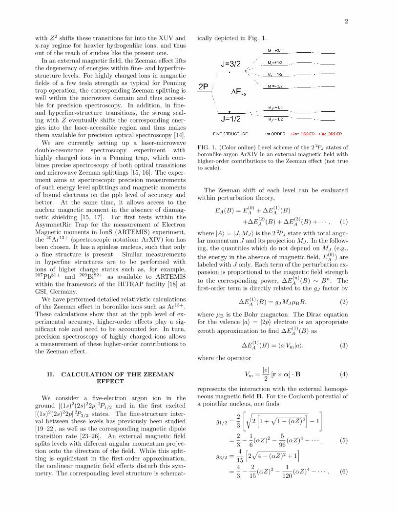
The technique of laser-microwave double-resonancespectroscopy has been applied in experiments withsingly charged ions [37–39]. Presently, the conceptcan be exemplified by Fig. 2. It shows all six com-ponents of the Zeeman-split magnetic dipole transi-tion between the two fine-structure states of a P elec-tron. Neighboring lines are all separated by aboutthe same frequency difference, because the upper-statelevel spacing is about twice as large as that in thelower state. If an ion gets excited by the most red-shifted frequencies (ν1 or ν2), the angular momen-tum projection is lowered by 1. The fluorescence lightcorresponding to these transitions is emitted mainlyalong the quantization axis with circular polarization.Yet a fraction can also be detected under radial ob-servation. This component is polarized parallel to theaxis. The frequencies ν3 and ν4 are the closest tothe field-free frequency. The corresponding transitionspreserve the angular momentum projection and can beobserved only radially and with perpendicular polar-ization. Excitation with the most blueshifted lines atν5 or ν6 increases the angular momentum projection.The emitted fluorescence follows the same distributionas in the case of ν1 or ν2, but has opposite helicity.
The basic idea of double-resonance spectroscopy iscontained in the following example: A closed opti-cal cycle between the extremal states |1/2,+1/2〉 and|3/2,+3/2〉 is driven resonantly by a laser at frequencyν6. The corresponding fluorescence light (dotted ar-row) is observed continuously. In the absence of mi-crowave radiation the fluorescence light intensity isconstant. When either of the microwave transitionsat νa or νd is driven resonantly, population is with-drawn from the optical cycle and the amount of flu-orescence light is reduced. Hence, the optical signalindicates when the desired microwave transition is res-onantly driven, yielding the desired Zeeman transitionfrequency. A detailed discussion of the applicabilityof this concept in different level-scheme situations isgiven in [15]. Note that all Zeeman sublevels can beaddressed individually since their separation is much
5
larger than the laser width and the Doppler widths ofthe optical transitions.
FIG. 2. (Color online) Spectroscopy of the 2 2P1/2-
2 2P3/2 fine-structure transition, as in a boronlike argon ionArXIV, with Zeeman effect. The level scheme (not true toscale) and all magnetic dipole transitions are shown. Solidarrows indicate excitation by laser photons, while dottedarrows are spontaneous decays. Gray double arrows rep-resent microwave transitions.
B. Application to an optical P doublet
In the present application, the optical transition isa ground-state fine-structure transition in a highlycharged ion, while the microwave transition occursbetween corresponding Zeeman sub-levels. Both aremagnetic dipole (M 1) transitions with accordinglylong lifetimes of the upper levels. By laser-microwavedouble-resonance spectroscopy, the Zeeman sublevelsplittings can be measured with high accuracy. Thisyields access to differences of the coefficients definedin Sec. II rather than to the values themselves. There-fore we abbreviate:
ai ≡ a(i)1/2(1/2)− a(i)1/2(−1/2), i = 1, 3,
bi ≡ a(i)3/2(3/2)− a(i)3/2(1/2), i = 1, 2, 3,
b′3 ≡ a(3)3/2(3/2).
Due to the tiny value of b′3B3 < 1 mHz, we cannot
distinguish b3 from −a(3)3/2(1/2).
The upper-level Zeeman splitting is of particularinterest, because here the quadratic shift actually hasa measurable effect on the Larmor frequencies. Wename the three frequencies νa, νb, and νc, while theground-state Larmor frequency is νd, as denoted inFig. 2.
The combination of particular frequencies can beused to disentangle the different orders:
νd = a1B + a3B3,
νa + νc = 2b1B + 2b3B3,
νa − νc = 2b2B2,
νa + νb + νc = 3b1B + 2b′3B3,
νa + νc − 2νb = 6b3B3 − 4b′3B
3.
Neglecting b′3B3, we can immediately derive b1, b2, b3
from the latter equations, provided the magnetic fieldstrength has been measured with corresponding accu-racy. In the lower state, the quadratic effect cancels.This is different for the cubic order: So far, we haveto use the theoretical prediction for a3 in order to de-termine a1. A similar procedure would yield b1 in thecase of an insufficient νb measurement:
g1/2µB
h≡ a1 =
1
B
(νd − a3B3
),
g3/2µB
h≡ b1 =
1
B
(νa + νc
2− b3B3
).
Under these conditions, we can imagine several dif-ferent spectroscopic options. All involve blue laserradiation (λ ≈ 441 nm) and a microwave field with atleast one of the aforementioned frequencies. There-fore, the term “double resonance” may be extendedto “triple” or even “quadruple” resonance. In anycase, the optical spectroscopy serves to prepare or de-tect population in specific Zeeman states and thus al-lows us to see whether the microwave frequency is atresonance with the transition of interest. The set fre-quency together with the measured response of theions is used to determine the Larmor frequency. Inthe following, we will explain the most useful and vi-able concept and just briefly mention variations.
For any microwave scan, we start with a spectrallybroad signal (statistical or a Landau-Zener sweep) anditeratively lower the width. This can be performedby an external modulation of the output frequency ofthe microwave generator. In addition, the modulationtechnique allows us to apply multiple sharp frequen-cies at once.
The ratio of gJ values in the respective states isclose to 2, namely, 2.007. The frequencies to be gen-erated before multiplication are, according to the cur-rent theoretical estimation,
νa/8 = 16.323 GHz,
νb/8 = 16.323 GHz,
νc/8 = 16.324 GHz,
νd/4 = 16.262 GHz.
These frequencies are well within the few-percentspectral acceptance of an active quadrupler for νd.We use an additional doubling stage for the upper-level Larmor frequencies νa, νb, and νc. Thus we can

6
address several upper-level Larmor transitions simul-taneously, namely, by nonlinear mixing of close-lyingfundamental frequencies.
The relatively long lifetime of 9.6 ms has two ben-efits: First, it allows a temporal separation of ex-citation and detection, and, second, the microwaveshave enough time to stimulate transitions betweenthe excited-level substates in the upper fine-structurelevel. Anyway, the precision of the upper-level Lar-mor frequencies is limited by the natural linewidth ofabout 100 Hz.
1. Separation of the linear and quadratic effects
The |1/2,+1/2〉 population is probed by a laser atfrequency ν6 (see Fig. 3). This drives the closed tran-sition to the |3/2,+3/2〉 sublevel. If the laser is res-onant, we repeatedly see fluorescence photons fromroughly half of all ions. When the microwave field isresonant with the upper-level Larmor frequency, thecycle will be disturbed. An additional decay channelis opened that leads via |3/2,+1/2〉 either back or intothe dark state |1/2,−1/2〉. Therefore, after a pumpingperiod with length depending on the respective inten-sities and temporal overlap of the exciting fields, thefluorescence signal will vanish. A microwave in reso-
FIG. 3. (Color online) Probe spectroscopy in the Zeeman-split fine-structure doublet. Solid arrows indicate the sat-urated probing and, optionally, pumping laser photons,while dotted arrows are spontaneous decays. Gray arrowsrepresent microwave-stimulated transitions.
nance with νd repumps at least half of the ions (theaccurate number again depends on the relative inten-sities) back to the bright state. This is a reversibleprocess. We can measure pumping and repumpingefficiencies over and over and arrive at a count ratethat depends on the frequencies only and not on thehistory of irradiation. This procedure defines a lineshape. However, the scan of a single parameter re-quires the others to be kept sufficiently stable. At least
the ground-state repumping can be done efficiently bysweeping over the resonance. This intensifies the sig-nal for finding the upper-level Larmor resonance. Amore general concept is to monitor the yielded fluores-cence intensity as a function of all three frequencies.The multiresonance condition will be represented as asaddle point in this map.
Simultaneous or alternating irradiation with an ad-ditional repumping laser beam would facilitate themeasurement. Unfortunately, this is currently not fea-sible, because the frequencies ν5 and ν6 are separatedby 65 GHz. There are no modulators producing suchfar-distant sidebands, and a second light source wouldbe needed. A weaker magnetic field or smaller gJ fac-tor would bring this method back into play.
This method may be inverted in the following sense:The microwave frequency νa is replaced by νc, whilethe laser frequency is reduced by 325 GHz from ν6to ν1. Given the spontaneous transition rate betweenadjacent Zeeman levels of the order of 10−10 s−1, theinverse processes are equivalent to the original ones.
2. Separation of the cubic effect
a. Saturated excitation. According to the abovearithmetic, many Zeeman coefficients can be derivedalready from the frequencies discussed so far. To im-prove the coefficient b1 or to get any reliable infor-mation about the cubic order, it is desirable to mea-sure νb as well. To this end, we look into a method
FIG. 4. (Color online) Pump spectroscopy in the Zeeman-split fine-structure doublet. Solid arrows indicate the sat-urated pumping laser photons, while dotted arrows arespontaneous decays. Projection-conserving decays of thestates |3/2,+1/2〉 and |3/2,−1/2〉 are preferred. Gray ar-rows represent microwave-stimulated transitions.
that uses laser pumping instead of probing. This isillustrated in Fig. 4: For instance, we depopulatethe sublevel |1/2,−1/2〉 by exciting ions in this stateto the |3/2,+1/2〉 state with the pump frequency ν5.This level can decay back to the original state or into
7
the dark state |1/2,+1/2〉. After a few cycles, thefluorescence will vanish. Additional irradiation of amicrowave at the lower-level resonant frequency willrepump ions to the state |1/2,−1/2〉. A continuousfluorescence signal is a signature of both waves beingin resonance with the corresponding transition.
As a side effect, this would even improve the two-dimensional line shape (the map of the fluorescenceintensity versus the two frequencies of the laser andthe microwave): The maximum of this can be deter-mined with higher accuracy than the above-mentionedsaddle point. On the downside, the detectable fluores-cence intensity suffers compared to the probe transi-tion, which is a pure |∆MJ | = 1 transition with en-hanced emission in the axial direction.
This argument leads back to the original chain ofthought: We can identify specific substates by the di-rectional characteristic and branching of different de-cay modes. If we drive the upper-level Larmor transi-tion from the |3/2,+1/2〉 state to |3/2,+3/2〉, ionswill decay in the projection-changing channel only.This should lead to a more intense optical signal.However, for this interference-prone signature, it isnecessary to have excellent control of the populationdistribution in the ground-state sublevels. If the driveworks efficiently, we see yet another effect: The pump-ing ends faster than before, because |3/2,+1/2〉 canstill decay into the bright state.
This study of pumping efficiencies works in a similarway for the transition from |3/2,+1/2〉 to |3/2,−1/2〉.The decay branching of the |3/2,+1/2〉 level is 2:1in favor of |1/2,+1/2〉, while the total decay rate isthe same as of the |3/2,+3/2〉 state. Now we candistinguish |3/2,+1/2〉 from |3/2,−1/2〉 in a spectro-scopic experiment: After excitation from |1/2,−1/2〉to |3/2,+1/2〉, ions usually come back with a proba-bility of 1/3, while the remaining ions fall into the darkstate |1/2,+1/2〉. A resonant microwave stimulationof the |3/2,+1/2〉 ↔ |3/2,−1/2〉 transition enhancesthe decay into the original state up to a probabilityof 2/3, which is a factor of 2 in pumping efficiency.An additional drive of the |3/2,−1/2〉 ↔ |3/2,−3/2〉transition could theoretically prevent the ions fromdecaying into the dark state at all.
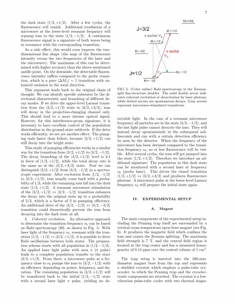
b. Coherent excitation. An alternative approachto determine the transition frequency νb can be basedon Rabi spectroscopy [40], as shown in Fig. 5. Withlaser light of the frequency ν5, resonant with the tran-sition |1/2,−1/2〉 ↔ |3/2,+1/2〉, it is possible to driveRabi oscillations between both states. The prepara-tion scheme starts with all population in |1/2,−1/2〉.An applied laser light pulse with area π (π pulse)leads to a complete population transfer to the state|3/2,+1/2〉. From there, a microwave pulse at a fre-quency close to νb pumps the ions to |3/2,−1/2〉 withan efficiency depending on power, frequency, and du-ration. The remaining population in |3/2,+1/2〉 willbe transferred back to the initial |1/2,−1/2〉 statewith a second laser light π pulse, yielding no de-
FIG. 5. (Color online) Rabi spectroscopy in the Zeeman-split fine-structure doublet. The solid double arrow indi-cates coherent excitation or deexcitation by laser photons,while dotted arrows are spontaneous decays. Gray arrowsrepresent microwave-stimulated transitions.
tectable light. In the case of a resonant microwavefrequency all particles are in the state |3/2,−1/2〉, andthe last light pulse cannot deexcite the ions. They willinstead decay spontaneously in the subsequent mil-liseconds and can with a certain detection efficiencybe seen by the detector. When the frequency of themicrowave has been detuned compared to the transi-tion frequency νb, no or less fluorescence will be visi-ble. After several cycles, the ions will get pumped intothe state |1/2,+1/2〉. Therefore we introduce an ad-ditional signature: The population in this dark statecan be monitored with a second laser at frequencyν6 (probe laser). This drives the closed transition|1/2,+1/2〉 ↔ |3/2,+3/2〉 and produces fluorescencephotons. A microwave pulse at the lower-level Larmorfrequency νd will prepare the initial state again.
IV. EXPERIMENTAL SETUP
A. Magnet
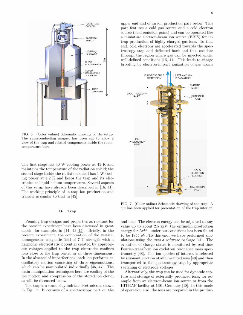
The main components of the experimental setup in-cluding the Penning trap itself are surrounded by avertical room-temperature open-bore magnet (see Fig.6). It produces the magnetic field which confines theions and causes the Zeeman splitting. The maximumfield strength is 7 T, and the central field region islocated at the trap center and has a measured homo-geneity of 0.14 ppm over the central volume of 1 cm3.
The trap setup is inserted into the 160-mm-diameter magnet bore from the top and representsa shielded cryostat which employs a pulse-tube cry-ocooler, to which the Penning trap and the cryoelec-tronic components are attached. The cryostat is a low-vibration pulse-tube cooler with two thermal stages.
8
FIG. 6. (Color online) Schematic drawing of the setup.The superconducting magnet has been cut to allow aview of the trap and related components inside the room-temperature bore.
The first stage has 40 W cooling power at 45 K andmaintains the temperature of the radiation shield; thesecond stage inside the radiation shield has 1 W cool-ing power at 4.2 K and keeps the trap and its elec-tronics at liquid-helium temperature. Several aspectsof this setup have already been described in [16, 41].The working principle of in-trap ion production andtransfer is similar to that in [42].
B. Trap
Penning trap designs and properties as relevant forthe present experiment have been discussed in greatdepth, for example, in [14, 43–45]. Briefly, in thepresent experiment, the combination of the verticalhomogeneous magnetic field of 7 T strength with aharmonic electrostatic potential created by appropri-ate voltages applied to the trap electrodes confinesions close to the trap center in all three dimensions.In the absence of imperfections, each ion performs anoscillatory motion consisting of three eigenmotions,which can be manipulated individually [46, 47]. Themain manipulation techniques here are cooling of theion motion and compression of the stored ion cloud,as will be discussed below.
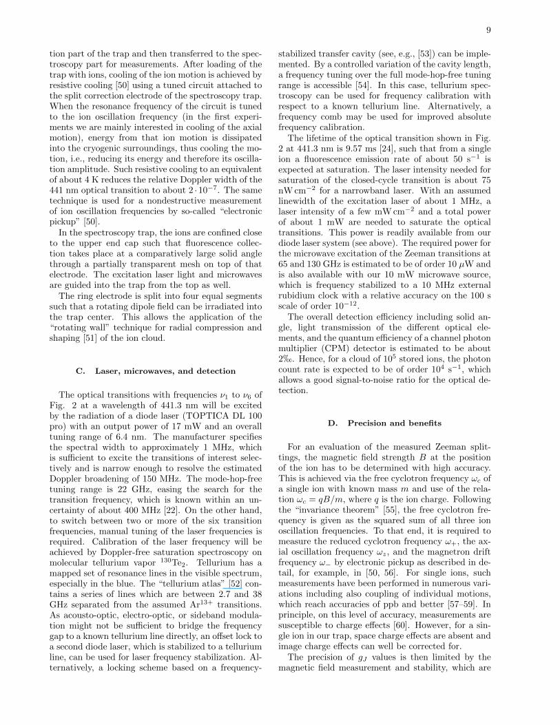
The trap is a stack of cylindrical electrodes as shownin Fig. 7. It consists of a spectroscopy part on the
upper end and of an ion production part below. Thispart features a cold gas source and a cold electronsource (field emission point) and can be operated likea miniature electron-beam ion source (EBIS) for in-trap production of highly charged gas ions. To thatend, cold electrons are accelerated towards the spec-troscopy trap and deflected back and thus oscillatethrough the region where gas can be injected underwell-defined conditions [16, 41]. This leads to chargebreeding by electron-impact ionization of gas atoms
FIG. 7. (Color online) Schematic drawing of the trap. Acut has been applied for presentation of the trap interior.
and ions. The electron energy can be adjusted to anyvalue up to about 2.5 keV, the optimum productionenergy for Ar13+ under our conditions has been foundto be 1855 eV. To this end, we have performed sim-ulations using the cbsim software package [41]. Theevolution of charge states is monitored by real-timeFourier-transform ion cyclotron resonance mass spec-trometry [48]. The ion species of interest is selectedby resonant ejection of all unwanted ions [49] and thentransported to the spectroscopy trap by appropriateswitching of electrode voltages.
Alternatively, the trap can be used for dynamic cap-ture and storage of externally produced ions, for ex-ample from an electron-beam ion source or from theHITRAP facility at GSI, Germany [18]. In this modeof operation also, the ions are prepared in the produc-
9
tion part of the trap and then transferred to the spec-troscopy part for measurements. After loading of thetrap with ions, cooling of the ion motion is achieved byresistive cooling [50] using a tuned circuit attached tothe split correction electrode of the spectroscopy trap.When the resonance frequency of the circuit is tunedto the ion oscillation frequency (in the first experi-ments we are mainly interested in cooling of the axialmotion), energy from that ion motion is dissipatedinto the cryogenic surroundings, thus cooling the mo-tion, i.e., reducing its energy and therefore its oscilla-tion amplitude. Such resistive cooling to an equivalentof about 4 K reduces the relative Doppler width of the441 nm optical transition to about 2 ·10−7. The sametechnique is used for a nondestructive measurementof ion oscillation frequencies by so-called “electronicpickup” [50].
In the spectroscopy trap, the ions are confined closeto the upper end cap such that fluorescence collec-tion takes place at a comparatively large solid anglethrough a partially transparent mesh on top of thatelectrode. The excitation laser light and microwavesare guided into the trap from the top as well.
The ring electrode is split into four equal segmentssuch that a rotating dipole field can be irradiated intothe trap center. This allows the application of the“rotating wall” technique for radial compression andshaping [51] of the ion cloud.
C. Laser, microwaves, and detection
The optical transitions with frequencies ν1 to ν6 ofFig. 2 at a wavelength of 441.3 nm will be excitedby the radiation of a diode laser (TOPTICA DL 100pro) with an output power of 17 mW and an overalltuning range of 6.4 nm. The manufacturer specifiesthe spectral width to approximately 1 MHz, whichis sufficient to excite the transitions of interest selec-tively and is narrow enough to resolve the estimatedDoppler broadening of 150 MHz. The mode-hop-freetuning range is 22 GHz, easing the search for thetransition frequency, which is known within an un-certainty of about 400 MHz [22]. On the other hand,to switch between two or more of the six transitionfrequencies, manual tuning of the laser frequencies isrequired. Calibration of the laser frequency will beachieved by Doppler-free saturation spectroscopy onmolecular tellurium vapor 130Te2. Tellurium has amapped set of resonance lines in the visible spectrum,especially in the blue. The “tellurium atlas” [52] con-tains a series of lines which are between 2.7 and 38GHz separated from the assumed Ar13+ transitions.As acousto-optic, electro-optic, or sideband modula-tion might not be sufficient to bridge the frequencygap to a known tellurium line directly, an offset lock toa second diode laser, which is stabilized to a telluriumline, can be used for laser frequency stabilization. Al-ternatively, a locking scheme based on a frequency-
stabilized transfer cavity (see, e.g., [53]) can be imple-mented. By a controlled variation of the cavity length,a frequency tuning over the full mode-hop-free tuningrange is accessible [54]. In this case, tellurium spec-troscopy can be used for frequency calibration withrespect to a known tellurium line. Alternatively, afrequency comb may be used for improved absolutefrequency calibration.
The lifetime of the optical transition shown in Fig.2 at 441.3 nm is 9.57 ms [24], such that from a singleion a fluorescence emission rate of about 50 s−1 isexpected at saturation. The laser intensity needed forsaturation of the closed-cycle transition is about 75nW cm−2 for a narrowband laser. With an assumedlinewidth of the excitation laser of about 1 MHz, alaser intensity of a few mW cm−2 and a total powerof about 1 mW are needed to saturate the opticaltransitions. This power is readily available from ourdiode laser system (see above). The required power forthe microwave excitation of the Zeeman transitions at65 and 130 GHz is estimated to be of order 10 µW andis also available with our 10 mW microwave source,which is frequency stabilized to a 10 MHz externalrubidium clock with a relative accuracy on the 100 sscale of order 10−12.
The overall detection efficiency including solid an-gle, light transmission of the different optical ele-ments, and the quantum efficiency of a channel photonmultiplier (CPM) detector is estimated to be about2h. Hence, for a cloud of 105 stored ions, the photoncount rate is expected to be of order 104 s−1, whichallows a good signal-to-noise ratio for the optical de-tection.
D. Precision and benefits
For an evaluation of the measured Zeeman split-tings, the magnetic field strength B at the positionof the ion has to be determined with high accuracy.This is achieved via the free cyclotron frequency ωc ofa single ion with known mass m and use of the rela-tion ωc = qB/m, where q is the ion charge. Followingthe “invariance theorem” [55], the free cyclotron fre-quency is given as the squared sum of all three ionoscillation frequencies. To that end, it is required tomeasure the reduced cyclotron frequency ω+, the ax-ial oscillation frequency ωz, and the magnetron driftfrequency ω− by electronic pickup as described in de-tail, for example, in [50, 56]. For single ions, suchmeasurements have been performed in numerous vari-ations including also coupling of individual motions,which reach accuracies of ppb and better [57–59]. Inprinciple, on this level of accuracy, measurements aresusceptible to charge effects [60]. However, for a sin-gle ion in our trap, space charge effects are absent andimage charge effects can well be corrected for.
The precision of gJ values is then limited by themagnetic field measurement and stability, which are
10
typically in the ppb regime within the usual measure-ment times. In the case of boronlike argon, the upper-level Larmor frequency sets a comparable limit by itsnatural width. The Zeeman splitting in longer-livedstates, however, can be determined with the signifi-cantly higher accuracy of microwave and rf technol-ogy. The present system involves two different gJ fac-tors. The relation of simultaneously measured Larmorfrequencies may profit from this: In general, one gJfactor may be used as reference for the other insteadof the cyclotron frequency.
This is of particular interest because of the followingphysical motivation: The leading-order value of mostgJ factors is a rational number given by the Lande for-mula for coupling of spin and orbital moments. For in-stance, in a P doublet, the lower and upper levels haveg1/2 = 2/3 and g3/2 = 4/3, respectively. Deviationsfrom the ratio of exactly 2 are of purely relativisticand quantum-electrodynamical origin, as discussed inSec. II. They usually do not scale with the same ra-tional factor; hence they are not canceled, but refinedfrom the trivial offset, by the arithmetic operationg′ = g3/2 − 2g1/2. This small difference can be mea-sured more directly by modulation of the fundamen-tal microwave oscillation with a finite radio frequencyinstead of generating the radiation with two separatemicrowave synthesizers. Carrier and sidebands will bemixed in the up-conversion process and the frequencyinterval, as defined by the modulation, is conserved.Then both Zeeman transitions are driven simultane-ously with a single source, and the refined value g′ isderived from the radio frequency with its attendantprecision. This removes the uncertainty due to can-cellation of two microwave frequencies.
The deviation of this radio frequency from zeroreflects the deviation of the actual gJ factors from
the Lande formula and allows determination of theanomalous contributions without the precision restric-tion caused by the cyclotron frequency.
V. SUMMARY AND OUTLOOK
We have shown that an understanding of the Zee-man effect at higher orders also is indispensable forspectroscopy of highly charged ions at the current levelof experimental precision. We have provided a de-tailed calculation of the first-, second-, and third-orderZeeman effects for a boronlike system as presentlyunder investigation. Experimental schemes for theseparation of the respective contributions to the Zee-man effect have been given, together with a descrip-tion of the corresponding experimental setup for in-trap laser-microwave double-resonance spectroscopyof confined, highly charged ions. Such measurementsyield well-defined access to higher-order Zeeman ef-fects in highly charged ions.
ACKNOWLEDGMENTS
This work has been supported in part by DFG(Grants No. VO 1707/1-2 and No. BI 647/4-1) andGSI. D.A.G., A.V.V., M.M.S., V.M.S., and G.P. re-ceived support from a grant of the President of theRussian Federation (Grant No. MK-3215.2011.2), byRFBR (Grants No. 12-02-31803 and No. 10-02-00450), and by the Ministry of Education and Scienceof Russian Federation. D.A.G. acknowledges supportby the FAIR-Russia Research Center, and by the “Dy-nasty” Foundation. D.L. is supported by IMPRS-QDHeidelberg.
[1] F. A. Jenkins and E. Segre. Phys. Rev., 55(52), 1939.[2] L. I. Schiff and H. Snyder. Phys. Rev., 55(59), 1939.[3] W. R. S. Garton and F. S. Tomkins. Astrophys. J.,
158(839), 1969.[4] G. Feinberg, A. Rich, and J. Sucher. Phys. Rev. A,
41(3478), 1990.[5] M. Raoult, S. Guizard, D. Gauyacq, and A. Matzkin.
J. Phys. B, 38(171), 2005.[6] K. Numazaki, H. Imai, and A. Morinaga. Phys. Rev.
A, 81(032124), 2010.[7] G. W. Preston. Astrophys. J., 160(L143), 1970.[8] T. Hamada. Publ. Astron. Soc. Jpn., 23(271), 1971.[9] S. B. Kemic. Astrophys. Space Sci., 36(459), 1974.
[10] R. Williams and A. Mason. Rev. Mex. Astron. As-trofiz., Ser. Conf., 26(33), 2006.
[11] C. Moran, T. R. Marsh, and V. S. Dhillon. Mon. Not.R. Astron. Soc., 299(218), 1998.
[12] H. F. Beyer and V. P. Shevelko. Introduction to thePhysics of Highly Charged Ions. Institute of Physics,London, 2002.
[13] H. F. Beyer and V. P. Shevelko. Atomic Physics withHeavy Ions. Springer, Heidelberg, 1999.
[14] M. Vogel and W. Quint. Phys. Rep., 490(1), 2010.[15] W. Quint, D. L. Moskovkhin, V. M. Shabaev, and
M. Vogel. Phys. Rev. A, 78(032517), 2008.[16] D. von Lindenfels, N. Brantjes, G. Birkl, W. Quint,
V. Shabaev, and M. Vogel. Can. J. Phys., 89(79),2011.
[17] V. A. Yerokhin and K. Pachucki and Z. Harman andC. H. Keitel. Phys. Rev. Lett., 107(043004), 2011.
[18] H.-J. Kluge, T. Beier, K. Blaum, L. Dahl, S. Eliseev,F. Herfurth, B. Hofmann, O. Kester, S. Koszudowski,C. Kozhuharov, G. Maero, W. Nortershauser, J. Pfis-ter, W. Quint, U. Ratzinger, A. Schempp, R. Schuch,Th. Stohlker, R. C. Thompson, M. Vogel, G. Vorob-jev, D. F. A. Winters, and G. Werth. Adv. QuantumChem., 53(83), 2008.
[19] I. Draganic, J. R. Crespo Lopez-Urrutia, R. DuBois,S. Fritzsche, V. M. Shabaev, R. Soria Orts, I. I.Tupitsyn, Y. Zou, and J. Ullrich. Phys. Rev. Lett.,91(183001), 2003.
11
[20] A. N. Artemyev, V. M. Shabaev, I. I. Tupitsyn,G. Plunien, and V. A. Yerokhin. Phys. Rev. Lett.,98(173004), 2007.
[21] R. Soria Orts, J. R. Crespo Lopez-Urrutia, H. Bruhns,A. J. Gonzalez Martınez, Z. Harman, U. D.Jentschura, C. H. Keitel, A. Lapierre, H. Tawara, I. I.Tupitsyn, J. Ullrich, and A. V. Volotka. Phys. Rev.A, 76(052501), 2007.
[22] V. Mackel, R. Klawitter, G. Brenner, J. R. Cre-spo Lopez-Urrutia, and J. Ullrich. Phys. Rev. Lett.,107(143002), 2011.
[23] I. I. Tupitsyn, A. V. Volotka, D. A. Glazov, V. M.Shabaev, G. Plunien, J. R. Crespo Lopez-Urrutia,A. Lapierre, and J. Ullrich. Phys. Rev. A, 72(062503),2005.
[24] A. Lapierre, U. D. Jentschura, J. R. Crespo Lopez-Urrutia, J. Braun, G. Brenner, H. Bruhns, D. Fis-cher, A. J. Gonzalez Martınez, Z. Harman, W. R.Johnson, C. H. Keitel, V. Mironov, C. J. Osborne,G. Sikler, R. Soria Orts, V. Shabaev, H. Tawara, I. I.Tupitsyn, J. Ullrich, and A. Volotka. Phys. Rev. Lett.,95(183001), 2005.
[25] A. V. Volotka, D. A. Glazov, G. Plunien, V. M.Shabaev, and I. I. Tupitsyn. Eur. Phys. J. D, 38(293),2006.
[26] A. V. Volotka, D. A. Glazov, G. Plunien, V. M.Shabaev, and I. I. Tupitsyn. Eur. Phys. J. D, 48(167),2008.
[27] D. A. Glazov, A. V. Volotka, A. A. Schepetnov, M. M.Sokolov, V. M. Shabaev, I. I. Tupitsyn, and G. Plu-nien. Phys. Scr. (to be published).
[28] S. Sturm, A. Wagner, B. Schabinger, J. Zatorski,Z. Harman, W. Quint, G. Werth, C. H. Keitel, andK. Blaum. Phys. Rev. Lett., 107(023002), 2011.
[29] A. Wagner, S. Sturm, F. Kohler, D. A. Glazov,A. V. Volotka, G. Plunien, W. Quint, G. Werth,V. M. Shabaev, and K. Blaum. Phys. Rev. Lett.,110(033003), 2013.
[30] V. M. Shabaev, I. I. Tupitsyn, V. A. Yerokhin, G. Plu-nien, and G. Soff. Phys. Rev. Lett., 93(130405), 2004.
[31] J. Sapirstein and W. R. Johnson. J. Phys. B,29(5213), 1996.
[32] R. Cowan. The Theory of Atomic Spectra. Universityof California Press, Berkeley, CA, 1981.
[33] J. Sapirstein and K. T. Cheng. Phys. Rev. A,66(042501), 2002.
[34] D. A. Glazov, A. V. Volotka, V. M. Shabaev, I. I.Tupitsyn, and G. Plunien. Phys. Lett. A, 357(330),2006.
[35] A. V. Volotka, D. A. Glazov, I. I. Tupitsyn, N. S.Oreshkina, G. Plunien, and V. M. Shabaev. Phys.Rev. A, 78(062507), 2008.
[36] I. I. Tupitsyn. 2012.[37] F. Arbes, M. Benzing, Th. Gudjons, F. Kurth, and
G. Werth. Z. Phys. D, 31(27), 1994.[38] A. Munch, M. Berkler, Ch. Gerz, D. Wilsdorf, and
G. Werth. Phys. Rev. A, 35(4147), 1987.[39] F. Arbes, O. Becker, H. Knab, K. H. Knoll, and
G. Werth. Nucl. Instrum. Methods Phys. Res. B,70(494), 1992.
[40] W. Demtroder. Laserspektroskopie. Springer, Berlin,1993.
[41] D. von Lindenfels. Diploma thesis, University of Hei-delberg, 2010.
[42] H. Haffner, T. Beier, S. Djekic, N. Hermanspahn, H.-J. Kluge, W. Quint, S. Stahl, J. Verdu, T. Valenzuela,and G. Werth. Eur. Phys. J. D, 22(163), 2003.
[43] L. S. Brown and G. Gabrielse. Rev. Mod. Phys.,58(233), 1986.
[44] G. Gabrielse, L. Haarsma, and S. L. Rolston. Int. J.Mass Spectrom. Ion Process., 88(319), 1989.
[45] F. G. Major, V. N. Gheorghe, and G. Werth. ChargedParticle Traps. Springer, Heidelberg, 2005.
[46] S. Djekic, J. Alonso, H.-J. Kluge, W. Quint, S. Stahl,T. Valenzuela, J. Verdu, M. Vogel, and G. Werth.Eur. Phys. J. D, 31(451), 2004.
[47] M. Vogel, W. Quint, and W. Nortershauser. Sensors,10(2169), 2010.
[48] A. G. Marshall, C. L. Hendrickson, and G. S. Jackson.Mass Spectrom. Rev., 17(1), 1998.
[49] S. Guan and A. G. Marshall. Anal. Chem., 65(1288),1993.
[50] D. J. Wineland and H. G. Dehmelt. J. Appl. Phys.,46(919), 1975.
[51] S. Bharadia, M. Vogel, D. M. Segal, and R. C. Thomp-son. Appl. Phys. B: Lasers Opt., 107(1105), 2012.
[52] J. Cariou and P. Luc. Atlas du Spectre d’Absorption dela Molecule Tellure. CNRS Laboratoire Aime-Cotton,Paris, 1980.
[53] S. Albrecht, S. Altenburg, C. Siegel, N. Herschbach,and G. Birkl. Appl. Phys. B: Lasers Opt., 107(1069),2012.
[54] S. Albrecht, H. Jestadt, and G. Birkl. 2011.[55] L. S. Brown and G. Gabrielse. Phys. Rev. A, 25(2423),
1982.[56] L. Gruber, J. P. Holder, and D. Schneider. Phys. Scr.,
71(60), 2005.[57] K. Blaum. Phys. Rep., 425(1), 2006.[58] S. Ulmer, K. Blaum, H. Kracke, A. Mooser, W. Quint,
C. C. Rodegheri, and J. Walz. Phys. Rev. Lett.,107(103002), 2011.
[59] S. Sturm, A. Wagner, B. Schabinger, and K. Blaum.Phys. Rev. Lett., 107(143003), 2011.
[60] D. F. A. Winters, M. Vogel, D. M. Segal, and R. C.Thompson. J. Phys. B, 39(3131), 2006.
Related Documents
![arXiv:1709.00783v2 [physics.plasm-ph] 3 Oct 2017 · systems, the Penning-Malmberg trap and the magnetic dipole trap. ... [17, 18] and represent a promising source of applications](https://static.cupdf.com/doc/110x72/5fc3b72278634101a11a5531/arxiv170900783v2-3-oct-2017-systems-the-penning-malmberg-trap-and-the-magnetic.jpg)