Experiment-1 Introduction to the DSP-based Electric-Drives System 1.1 Introduction There are four major components of the DSP-based electric-drives system, which will be used to perform all the experiments in this course. They are as follows: 1) Motor coupling system, 2) Power Electronics Drives Board, 3) DSP based DS1104 R&D controller card and CP 1104 I/O board and 4) MATLAB Simulink and Control-desk. In this experiment, you will be briefly introduced to the role of above mentioned four components in the DSP-based electric-drives system. An example of speed-control of a DC-motor will be demonstrated. The Simulink file and Control-desk layout will be supplied to perform this experiment. The communication between the four components will be explained while controlling the speed of the motor. Section 1.2 details the DSP-based electric-drives system vis-à-vis the role of the four components listed above. In Section 1.3 a step-by-step procedure to run the DC motor speed-control will be performed. 1.2 DSP-based electric-drives system Fig. 1.1 shows the block diagram of the DSP-based electric-drives system. Motor coupling system: This system contains the motor that needs to be characterized or controlled. The system has a mechanical coupling arrangement to couple two electric machines. The motor under test (MUT) whose speed/torque needs to be controlled, could be either a DC motor or a Three-phase induction motor or a Three-phase Permanent-Magnet AC (PMAC) motor. The system also has an encoder mounted on the machine which is used to measure the speed of the MUT. This can be used for close loop feedback speed-control of the motor. The motor demands a controlled pulse-width-modulated (PWM) voltage to run at controlled speed or torque. The PWM voltage is generated by Power Electronics Drives Board (briefed next); the voltage source thus generated is connected to the motor coupling system as shown in Fig 1.2.

Welcome message from author
This document is posted to help you gain knowledge. Please leave a comment to let me know what you think about it! Share it to your friends and learn new things together.
Transcript

E x p e r i m e n t - 1
I n t r o d u c t i o n t o t h e D S P - b a s e d
E l e c t r i c - D r i v e s S y s t e m
1.1 Introduction
There are four major components of the DSP-based electric-drives system, which will be used to
perform all the experiments in this course. They are as follows: 1) Motor coupling system,
2) Power Electronics Drives Board, 3) DSP based DS1104 R&D controller card and CP 1104 I/O
board and 4) MATLAB Simulink and Control-desk. In this experiment, you will be briefly
introduced to the role of above mentioned four components in the DSP-based electric-drives
system. An example of speed-control of a DC-motor will be demonstrated. The Simulink file and
Control-desk layout will be supplied to perform this experiment. The communication between the
four components will be explained while controlling the speed of the motor. Section 1.2 details the
DSP-based electric-drives system vis-à-vis the role of the four components listed above. In Section
1.3 a step-by-step procedure to run the DC motor speed-control will be performed.
1.2 DSP-based electric-drives system
Fig. 1.1 shows the block diagram of the DSP-based electric-drives system.
Motor coupling system: This system contains the motor that needs to be characterized or
controlled. The system has a mechanical coupling arrangement to couple two electric
machines. The motor under test (MUT) whose speed/torque needs to be controlled, could be
either a DC motor or a Three-phase induction motor or a Three-phase Permanent-Magnet AC
(PMAC) motor. The system also has an encoder mounted on the machine which is used to
measure the speed of the MUT. This can be used for close loop feedback speed-control of the
motor. The motor demands a controlled pulse-width-modulated (PWM) voltage to run at
controlled speed or torque. The PWM voltage is generated by Power Electronics Drives Board
(briefed next); the voltage source thus generated is connected to the motor coupling system as
shown in Fig 1.2.

CURR B1CURR A1 CURR A2 CURR B2
GND
+42 V
ENCODER
To INC 1/INC 2
(on CP 1104)
CP 1104 I/O board
42
V D
C P
ow
er
Su
pp
ly
A 1 B 1 C 1 C 2B 2A 2
Slave I/O PWM
Input
+12 V
VOLT DC
Power Electronics Drive
Board
Motor coupling system
ADC and DAC interface,
Digitial I/O, Encoder interface
and RS232
Computer
MATLAB-
Simulink
DS1104 R&D Controller Card
Control-desk
Communication between Control-
desk and Hardware in real-time
Motor Current, DC Voltage
etc. for feedback control
Figure 1.1: DSP-based electric-drives laboratory system
Figure 1.2: Motor Coupling System showing DC Motor, DC Generator and Encoder
DC Generator DC Motor Encoder
Power Electronics Drives Board: This board has the capability to generate two independent
PWM voltage sources (A1B1C1 and A2B2C2) from a constant DC voltage source (see Fig 1 in
Appendix). Hence two machines can be controlled independently for independent control of
variables, at the same time. This board also provides the motor phase currents, dc-bus voltage
etc. to control the motor for a desired speed or torque. To generate the controlled PWM voltage
source, this board requires various digital control signals. These control signals dictate the
magnitude and phase of the PWM voltage source. They are generated by the DS1104 R&D
Controller board inside the computer.
DS1104 R&D controller Board and CP 1104 I/O board: In each discrete-time-step, the
DS1104 controller board takes some action to generate the digital control signals. The type of
action is governed by what we have programmed in this board with the help of MATLAB-
Simulink real-time interface. This board monitors the input (i.e. motor current, speed, voltage
etc) with the help of CP1104 I/O board in each discrete-time step. Based on the inputs and the
variables that need to be controlled (i.e. motor speed or torque); it takes the programmed action
to generate the controlled digital signals. The CP1104 I/O board is an input-output interface
board between the Power Electronics Drives Board and DS1104 controller board. It takes the
motor current, dc-voltage etc. from the Power Electronics Drives Board and also, speed signal
(from encoder) from motor coupling system, to the DS1104 controller board. In turn, the
controlled digital signals supplied by DS1104 controller board are taken to the Power
Electronics Drives Board by CP1104.
MATLAB Simulink and Control-desk (Programming DS1104 and control in real-time):
Simulink is a software program with which one can do model-based design such as designing a
control system for a DC motor speed-control. The I/O ports of CP 1104 are accessible from
inside the Simulink library browser. Creating a program in Simulink and the procedure to use
the I/O port of CP 1104 will be detailed in future experiments. At this stage, let us assume that
we have created a control-system inside the Simulink that can control the speed of a DC
motor. When you build the Simulink control-system (pressing CTRL+B) by using real-time
option, it implements the whole system inside the DSP of DS1104 board, i.e. the control-
system that was earlier in software (Simulink) gets converted into a real-time system on
hardware (DS1104). Simulink generates a *.sdf file when you build (CTRL+B) the control-

system. This file gives access to the variables of control-system (like reference speed, gain,
tuning the controller etc) to a separate software called Control-desk. In this software a control
panel (see Fig 1.3) can be created that can change the variables of control-system in real time
to communicate with DS1104 and hence change the reference quantities such as the speed or
torque of the motor.
1.3 Demonstration of Speed Control of a DC motor
The system for the speed-control of a DC motor is shown in Fig 1.3. Note that the currA1 (i.e.
phase-current of DC motor) and encoder signal (speed of DC motor) is fed back to the DS1104
board via CP 1104. The requirement of feeding back phase-current and speed of the motor will be
studied in experiment-4. For now, assume that these two quantities are required to control the
speed of DC motor. Perform the following steps to run the experiment. The communication
between the four components (explained in section 1.2) is detailed in each step, wherever
necessary.
Computer
MATLAB-
Simulink
DS1104 R&D Controller Card
Control-desk
CURR A1
ADC 5
INC 1
GND
+42 V
ENCODER
To INC 1
(on CP 1104)
From
ENCODER
CP 1104
42
V D
C P
ow
er
Su
pp
ly
B 1A 1
Slave I/O
PWM
+
_
+
_
Input
+12 V
*.sdf Control-desk provides a bi-
directional communication
between its control panel and
DS1104
Power Electronics Drive Board
Figure 1.3: Demonstration of DC motor speed-control
Connect the circuit as shown in Fig 1.3. You are given with files Exp1.mdl (Simulink control-
system file) and Exp1.lay (control panel in Control-desk). Create a new folder on desktop as
Exp1 and bring these two files into that folder. Open MATLAB Simulink and set the folder
Exp1 as the path of the current working directory. Verify in the command window for the
correct path (Fig 1.4). Open the Simulink file Exp1.mdl as shown in Fig 1.4.
Note : (When the MATLAB ® is opened, We chose RTI 1104 OK)
Figure 1.4: Opening the Simulink file Exp1.mdl, changing the path of current working directory
The Simulink file Exp1.mdl will look as shown in Fig 1.5. Open the simulation parameters (Or
could be Configuration parameters based on the MATLAB version) from the tools menu and
set the parameters as shown in Fig 1.5. The fixed step size is the same as the discrete-step,
which will be used by the DSP DS1104. This means that in every “discrete-step” the whole
program (i.e. control-system in this case) will be executed, I/O data will be exchanged and the
decision making will be done inside DS1104.
Type Vd=42 and Ts=1e-4 in the Matlab prompt. Press CTRL+B to build the control-system
in real-time now. Refer to Fig 1.6, note the sequence: 1) Compilation of C-code that is

generated by Simulink, which will be used to implement control-system in hardware DS1104,
2) Generation of Exp1.sdf file, which will be used later on by Control-desk, to access the
variables of control-system.
Figure 1.5: Simulink file Exp1.mdl, setting the simulation parameter
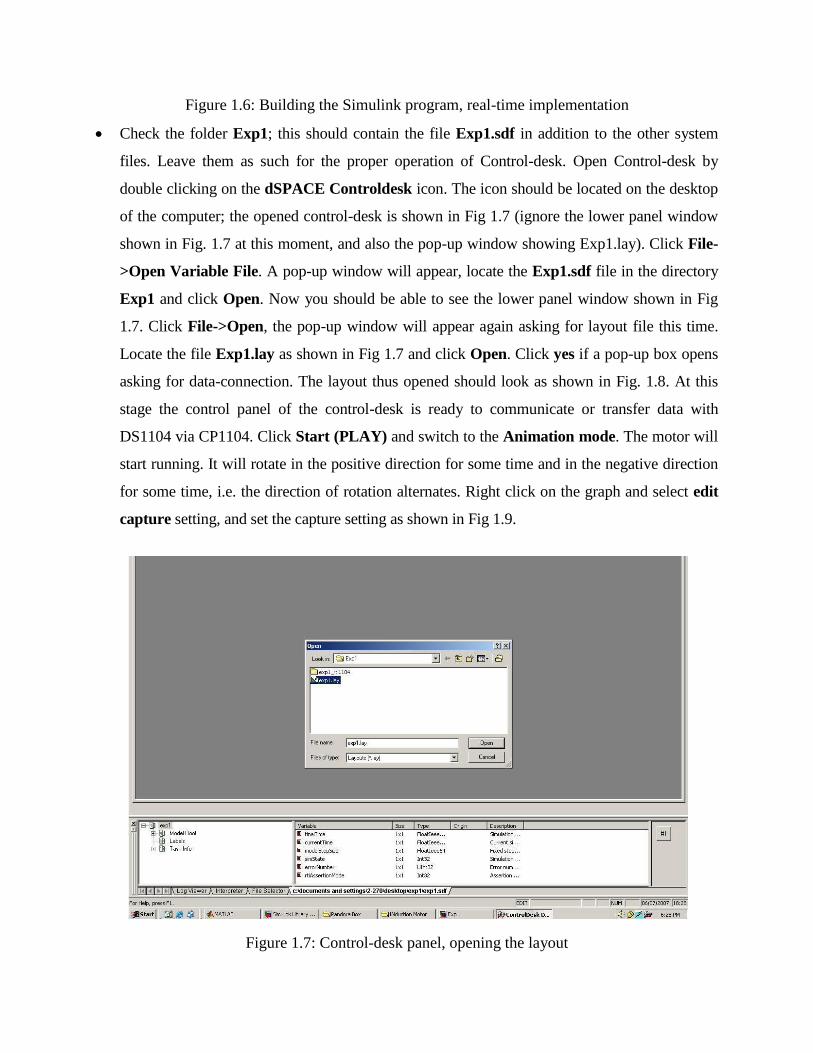
Figure 1.6: Building the Simulink program, real-time implementation
Check the folder Exp1; this should contain the file Exp1.sdf in addition to the other system
files. Leave them as such for the proper operation of Control-desk. Open Control-desk by
double clicking on the dSPACE Controldesk icon. The icon should be located on the desktop
of the computer; the opened control-desk is shown in Fig 1.7 (ignore the lower panel window
shown in Fig. 1.7 at this moment, and also the pop-up window showing Exp1.lay). Click File-
>Open Variable File. A pop-up window will appear, locate the Exp1.sdf file in the directory
Exp1 and click Open. Now you should be able to see the lower panel window shown in Fig
1.7. Click File->Open, the pop-up window will appear again asking for layout file this time.
Locate the file Exp1.lay as shown in Fig 1.7 and click Open. Click yes if a pop-up box opens
asking for data-connection. The layout thus opened should look as shown in Fig. 1.8. At this
stage the control panel of the control-desk is ready to communicate or transfer data with
DS1104 via CP1104. Click Start (PLAY) and switch to the Animation mode. The motor will
start running. It will rotate in the positive direction for some time and in the negative direction
for some time, i.e. the direction of rotation alternates. Right click on the graph and select edit
capture setting, and set the capture setting as shown in Fig 1.9.
Figure 1.7: Control-desk panel, opening the layout
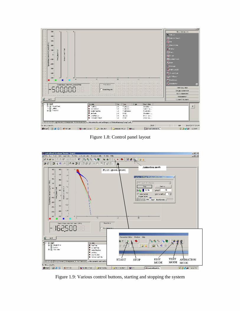
Figure 1.8: Control panel layout
Figure 1.9: Various control buttons, starting and stopping the system

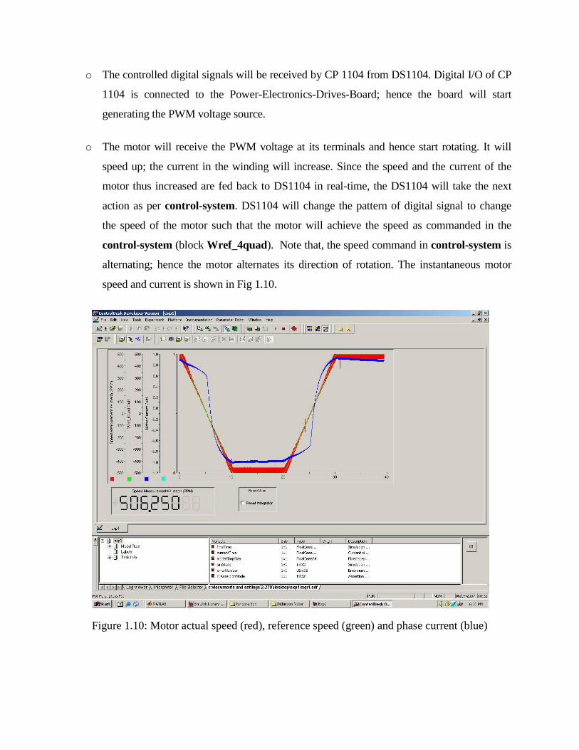
You should be able to observe the speed of the motor on control panel (Fig. 1.9). The
waveform for motor phase current, reference speed and actual speed is also shown. Press the
button Edit mode and then press STOP. Take the waveform as shown in Fig 1.10. Study the
explanations detailed next. The control-desk is able to access the following data with the help
of Exp1.sdf file:
o Actual Speed of the motor from W_mech subsystem which is inside the Simulink
control-system. You can open the subsystem W_mech; you will observe how the input
port INC1 (DS1104ENC_POS_C1) of CP 1104 is utilized to read the actual speed of the
motor. In the actual system, this port is connected (hardwired) to DS1104 though. But, this
port is also a part of Simulink control-system; hence it will be listed as a variable inside
the Exp1.sdf. Since the control-desk has access to the variables of control-system through
Exp1.sdf, hence the control-desk can read the port INC1, modify the data and send it back
to any of the output port of CP 1104, if necessary.
o Motor current, reference speed and actual speed can be observed in the same manner,
the communication among components is same as explained above.
o Note that, in this demonstration, we are only observing the variables of control-system
such as speed of the motor and current. It is also possible to change the variables of
control-system in real-time from the control panel. In the future experiments, this will be
done to give a reference speed command to run the motor at a desired speed. This reference
speed command will be changed in real-time to change the speed of the motor.
Sequence of events, when Start button is pressed on the control panel:
o DS1104 will be commanded to generate the controlled digital signals as per the speed and
phase-current of the motor in real-time. The information about the speed and current of the
motor is available to DS1104 via CP 1104, which is connected to the Power-Electronics-
Drives-Board (for current feedback) and the Motor coupling system (for speed feedback).
o The controlled digital signals will be received by CP 1104 from DS1104. Digital I/O of CP
1104 is connected to the Power-Electronics-Drives-Board; hence the board will start
generating the PWM voltage source.
o The motor will receive the PWM voltage at its terminals and hence start rotating. It will
speed up; the current in the winding will increase. Since the speed and the current of the
motor thus increased are fed back to DS1104 in real-time, the DS1104 will take the next
action as per control-system. DS1104 will change the pattern of digital signal to change
the speed of the motor such that the motor will achieve the speed as commanded in the
control-system (block Wref_4quad). Note that, the speed command in control-system is
alternating; hence the motor alternates its direction of rotation. The instantaneous motor
speed and current is shown in Fig 1.10.
Figure 1.10: Motor actual speed (red), reference speed (green) and phase current (blue)
Lab Report and
List the sequence of events i.e. the communication between the four major components when
STOP button is pressed in the control panel.
For this experiment draw a flowchart indicating step-by-step procedure to create a real-time
model in Simulink, which is followed by controlling a DC motor from control-desk.
Study thoroughly Appendix-A, pay special attention to the Power-Electronics-Drives-Board
features. Make a note of voltage and current scaling in the Drives board.
Draw a block diagram of Power-Electronics-Drives-Board indicating the inputs (like power
supplies, digital input, resets etc) and outputs (like PWM voltage, motor current, dc-bus voltage
etc).
Related Documents