Exhumation and Design of Anchorages in Chalk Barley, Mothersille, Weerasinghe 1 Exhumation and Design of Anchorages in Chalk. A D Barley - Managing Director, SBMA Systems Ltd. D Mothersille - Director, Geoserve Global Ltd. R B Weerasinghe - Director, Geoserve Global Ltd. Paper to be published in Geotechnical Engineering, ICE publication, April 2003.

Welcome message from author
This document is posted to help you gain knowledge. Please leave a comment to let me know what you think about it! Share it to your friends and learn new things together.
Transcript
Exhumation and Design of Anchorages in Chalk
Barley, Mothersille, Weerasinghe 1
Exhumation and Design of Anchorages in Chalk.
A D Barley - Managing Director, SBMA Systems Ltd.
D Mothersille - Director, Geoserve Global Ltd.
R B Weerasinghe - Director, Geoserve Global Ltd.
Paper to be published in Geotechnical Engineering, ICE publication, April 2003.
Exhumation and Design of Anchorages in Chalk
Barley, Mothersille, Weerasinghe 2
Synopsis
An anchorage test programme carried out on the site of deep basement construction in
Norwich, UK, allowed determination of anchorage capacities, creep characteristic data and the
exhumation of several anchor bodies in chalk.
This paper reports on the performance of the chalk based anchorages, the observation of
exhumed grout body shapes and sizes, extent of grout penetration into dissolution cavities,
pressure grouted fissures and the formation of grout cake around the grout body periphery.
Knowledge of construction techniques utilised for drilling, flushing, pre-grouting, redrilling,
pressure grouting and the general methods of control implemented to prevent dissolution cavity
collapse, has been related to the characteristics of the exhumed anchor bodies. Analysis of
these grout bodies has allowed the proposal of a failure mechanism, comprising shaft resistance
and shear of grouted fissures.
Tests were carried out on both conventional and single bore multiple anchors (SBMA). Using
short fixed length capacities with recently developed efficiency factors allowed accurate
evaluation of the ultimate capacity of a typical 10m fixed length conventional anchorage. This
design approach confirms that the SBMA system mobilised double the capacity of a
conventional 10m fixed anchor. Advancements in SMBA technology has enabled designs of
20m fixed lengths, safely supporting working loads of 3000 kN.
Exhumation and Design of Anchorages in Chalk
Barley, Mothersille, Weerasinghe 3
INTRODUCTION Although the installation of anchorages in chalk is not a new technology, there is a dearth of
published literature adequately relating the constructed product and the load transfer
mechanisms to the design approach. Most developments in ground anchorage technology over
the past 30 years have been driven by the sound application of reliable field data from
anchorage practitioners. One benefit of the rigorous construction and testing requirements for
ground anchorages is that analysis can be carried out on the field data acquired during
installation and testing. However, when the opportunity arises to exhume a tested anchorage
the observations from such operations are of immense value and allow correlation with the
associated ground conditions, construction technique, grout penetration and design.
This paper describes the testing, exhumation, inspection and analyses of anchorages installed
in chalk during the Castle Mall Development in Norwich, UK. The results have been used to
present a novel approach to design of the fixed anchor for an anchorage installed in fissured
chalk.
DESCRIPTION OF SITE The Castle Mall development is a two-story shopping centre with a basement up to 18m below
ground level adjacent to a five story underground car park in the centre of Norwich. The
permanent works comprised a 900mm diameter contiguous bored pile perimeter retaining wall
propped by the floor slabs. Temporary support of the perimeter wall during construction was
achieved using 1120 ground anchorages. Overall stability analysis determined that a limited
number of fixed anchor lengths would be located in the Norwich Crag (granular materials) but
that the majority would be founded in the underlying chalk stratum (Grose and Toone, 1992).
The site topography varies widely from 17 to 28 m OD resulting in retained heights of 7 to
18m. A five-phase site investigation comprised three inspection shafts up to 28m deep and 65
shell and auger boreholes up to 50m deep at the locations shown in Figure 1. The general
findings of these investigations are summarised in Table 1.
Exhumation and Design of Anchorages in Chalk
Barley, Mothersille, Weerasinghe 4
Description Level (m OD) Depth (m) Thickness (m)
MADE GROUND 17 to 29 0 0.1 to 11
Silty SANDS and GRAVELS with lenses and pockets of silty clay (NORWICH CRAG)
14 to 26 0 to 5 (av. 3m) 0 to 10
Very weak to moderately weak partly weathered to weathered white CHALK with flint bands (UPPER CHALK).
12 to 18 3 to 15 (av. 8m) Proved to 45m
Table 1 Summary of ground conditions at trial anchorage locations The groundwater table was at about 1m OD, some 8m below basement level. As part of the site
investigation 24 boreholes were put down outside the site to establish the stratigraphy and
confirm the Crag and Chalk were similar to the materials investigated in more detail
throughout the site. Within the fixed anchor zones, chalk with Munford (Ward et al, 1968)
grades IV to VI were encountered with SPT values ranging from 5 to 15 (Barley et al, 1992).
The presence of dissolution features within chalk is a well-documented phenomenon and they
were anticipated on this site. Not surprisingly, drilling and sampling anomalies, attributed to
dissolution features, were recorded to depths of 30m (-3m OD) in eight of the 65 boreholes.
These sub-vertical, steep sided features tended to be loosely infilled and sometimes associated
with voids. The anchorage design and construction techniques had to overcome the difficulties
that these dissolution features presented. Furthermore their location could not be predicted so
they would only be discovered and accommodated during anchorage construction.
ANCHORAGE CONSTRUCTION AND DESIGN All anchorages involved the use of duplex drilling and water flush techniques. Drill casing of
114mm diameter with a 120mm casing shoe was advanced to full depth of all anchors. During
drilling the majority of the chalk matrix was dissolved in the flush water and removed as a
milky solution. Drillers reported extensive bands of flint beds, plus randomly occurring flints
that were subsequently identified during anchorage exhumation as ranging in thickness from
20mm to over 1 m.
On this busy city site, where anchors passed below main streets, the risk of collapse of existing
cavities induced by anchoring operations caused great concern. Strict controls of drilling,
flushing, flush loss and precise rules for borehole termination and pre-grouting, or borehole
completion and pre-grouting were applied. Where pregrouting was required then a grout mix
Exhumation and Design of Anchorages in Chalk
Barley, Mothersille, Weerasinghe 5
containing sand filler was used in order to reduce unnecessary penetration into fissures and
cavities remote from the borehole. This also reduced grout flow characteristics and utilised a
more economic grout as a filler. The implementation of controlled ground improvement as an
integral element of the anchoring operations was specified in the contract. However, the
contract also ensured appropriate itemisation for reimbursement for materials used and
operations executed. Many of the 800 anchorages installed in the chalks did encounter full loss
of flush within cavities or flint beds. Pregrouting was therefore essential to mitigate the risk of
sink hole collapse. All anchorages were finally constructed using end of casing pressure-
grouting techniques utilising pressure of up to 6 bar and a 0.45 water/cement ratio grout.
For design purposes sacrificial test anchorages installed in similar chalk conditions some 1.5
km from Castle Mall provided values of ultimate bond stress of normal anchors with long fixed
lengths. However, such anchorages were unlikely to provide the ultimate anchor capacity
with the specified factor of safety of 2.5. As a result anchorages were designed as Single Bore
Multiple Anchor (SBMA) type, mobilising 525kN working load in the very weak chalk
utilising short efficient unit fixed lengths.
PROVING TESTS As part of the contract requirements, proving tests were specified in advance of the main
contract in order to demonstrate the designed anchorages performance in relation to the weak
ground conditions, workmanship and materials. Eighteen proving test anchorages were
required of which eleven were installed with fixed anchor lengths located in the underlying
chalks. The construction and performance of these test anchorages is fully described by Barley
et al (1992).
Having successfully tested the anchorages up to 2.4 times working load (1260kN), it was
established that during the site excavation at one location, it would be possible to exhume three
of the proving test anchorages installed in the chalk (see Table 2).
Exhumation and Design of Anchorages in Chalk
Barley, Mothersille, Weerasinghe 6
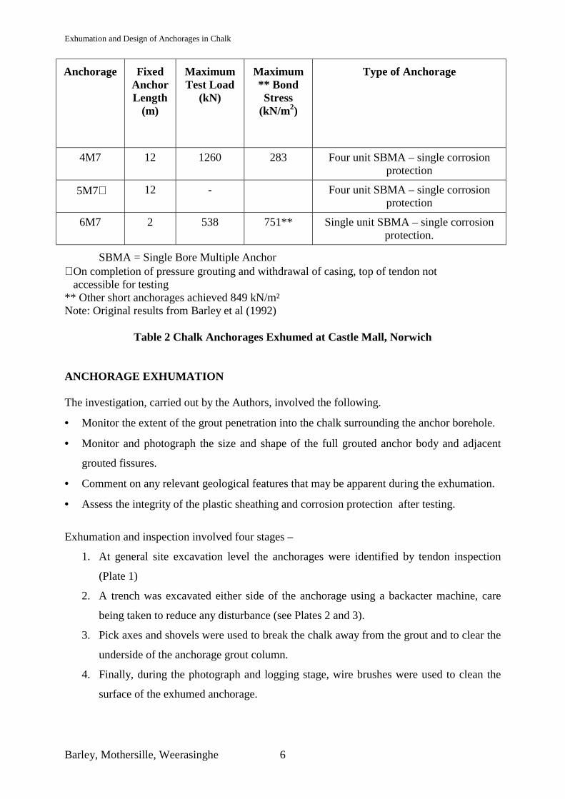
Anchorage Fixed Anchor Length
(m)
Maximum Test Load
(kN)
Maximum ** Bond Stress
(kN/m2)
Type of Anchorage
4M7 12 1260 283 Four unit SBMA – single corrosion protection
5M7∗ 12 - Four unit SBMA – single corrosion protection
6M7 2 538 751** Single unit SBMA – single corrosion protection.
SBMA = Single Bore Multiple Anchor ∗ On completion of pressure grouting and withdrawal of casing, top of tendon not accessible for testing ** Other short anchorages achieved 849 kN/m² Note: Original results from Barley et al (1992)
Table 2 Chalk Anchorages Exhumed at Castle Mall, Norwich
ANCHORAGE EXHUMATION The investigation, carried out by the Authors, involved the following.
• Monitor the extent of the grout penetration into the chalk surrounding the anchor borehole.
• Monitor and photograph the size and shape of the full grouted anchor body and adjacent
grouted fissures.
• Comment on any relevant geological features that may be apparent during the exhumation.
• Assess the integrity of the plastic sheathing and corrosion protection after testing.
Exhumation and inspection involved four stages –
1. At general site excavation level the anchorages were identified by tendon inspection
(Plate 1)
2. A trench was excavated either side of the anchorage using a backacter machine, care
being taken to reduce any disturbance (see Plates 2 and 3).
3. Pick axes and shovels were used to break the chalk away from the grout and to clear the
underside of the anchorage grout column.
4. Finally, during the photograph and logging stage, wire brushes were used to clean the
surface of the exhumed anchorage.
Exhumation and Design of Anchorages in Chalk
Barley, Mothersille, Weerasinghe 7
Certain sections broke during the above procedure but generally intact sections were cut in a
controlled manner using a Stihl Saw, then lifted and placed aside for observation and logging.
A valuable consideration for any future exhumations would be a staged approach whereby
finite lengths (1 to 1.5m) of fixed anchor are exposed, then cut and removed. By adopting this
method, the process of handling long slender sections of the anchor grout would be avoided
and facilitate easier inspection.
Anchorage 4M7
On recovery the 4680mm of fixed anchor grout was cut into four shorter lengths. Each length
was visually inspected and key physical dimensions recorded. Figure 2 graphically presents the
field measurements together with the original drilled diameter shown as a dashed line. The
Figure shows longitudinal sections (two axes) and one cross section through the grouted end
bulb.
Photographs corresponding to the sections in Figure 2 are presented in Plates 4, 5 and 6.
Over the last 520mm of the fixed anchor length a large bulbous formation of grout was
observed (Plate 7 and 8). Beyond the fixed anchor lay a separate mass of grout (1.2m x 1m x
0.45m) (Plate 9)
Anchorage 5M7
A 4990mm grout column was recovered from the lower free length as one section. In addition
a horizontal irregular ‘block’ of grout spanning either side of and perpendicular to the bore axis
was encountered. Figures 3 and 4 presents a graphical representation of the field measurements
for the free tendon length grout recovered and the large grout bulb. This is also shown in Plates
10 and 11.
Anchorage 6M7
A 770mm length of cylindrical grout column from the lower fixed length was recovered. No
bulbs or major sectional changes were observed.
Exhumation and Design of Anchorages in Chalk
Barley, Mothersille, Weerasinghe 8
OBSERVATIONS AND DISCUSSIONS Grouts and Grouting Pebble sized flints were observed at the contact interface between the grout and the chalk,
mainly at the underside but others randomly located. Larger, more irregular shaped flints were
also unevenly distributed. These flints, together with the grouted voids and fissures in the
chalk, accounted for the local variations in the surface roughness at the grout-chalk interface.
The presence of flints was observed over the free length of anchorage 5M7 and the bore
diameter was reasonably uniform. The exception to this was that large irregular shaped block
of grout attached to a section of the tendon free length 1500mm beneath the main section that
was logged. This block, 1840mm by 790mm, was considered to be an existing cavity that may
have been expanded during flushing prior to filling with by neat grout or the sand /cement
grout (Figure 4 and Plate 11).
At four locations in the fixed length of anchorage 4M7, localised increases in diameter were
observed. (see Figure 2 and Plate 4). The shape of these grout enlargements bore no
resemblance to the original drilled hole. The orientation of these enlargements was random,
and shapes varied from thick to thin fin-like protrusions on one side of the fixed anchor grout
to the bulbous shapes seen in Plate 4. It is considered that the general shape of the grout bulbs
reflect the grouting of existing voids or voids created by the water flushing operations and
pressure grouting. The larger grout bulb at the distal end of the fixed anchor 4M7 (Figure 2 and
Plates 7 and 8), is considered to have been formed as a result of extended flushing operation
carried out on the completion of the hole in an effort to clear loose spoil.
In 4M7 the grout was observed to be either a neat cement grout, or a sanded cement grout
surrounding a neat cement grout. The sanded grout is known to be from the pregrouting
operations, whilst the neat cement grout is the grout used during the final pressure grouting
carried out whilst withdrawing the drill casing
Besides the presence of the grouted voids the recovered bodies showed evidence that local
fissures in the chalk had been grouted along the length of the anchorage. This was evident from
thin 1 mm to 30mm wide broken fissure grout that protruded perpendicular to the
circumference of the grout shaft (Plate 12). The clean dark fracture of these grouted fissures
indicated the grout had penetrated into the fissures to some depth in the chalk mass, and that
during the process of exhumation, some of these thin protrusions, associated with fissure
Exhumation and Design of Anchorages in Chalk
Barley, Mothersille, Weerasinghe 9
grouting, had been severed from the grout mass. Other protrusions remained intact and resulted
in withdrawal of a fissure grouted chalk matrix. Removal of the chalk provided evidence of an
irregular skeletal grout body (Plate 13).
These observations of the grouted fissures within the chalk mass are consistent with those
recorded by Newman & Ingle (2002) in their inspection of exposed lance-grouted tunnel faces
in chalk of similar grading. Plate 14 illustrates the existence of “grout patches” and “grout
vein” adjacent to the grouted lanced hole.
Parts of the grout column exhumed from pressure grouted anchorage 4M7 (Plate 15),
highlights the presence of a dense, dark grout (grout “cake”) of thickness from zero to 20mm
around the grout body periphery (typical grout pressure between 5 and 10 bar). It is known that
during pressure application rapid squeezing of the excess water from within the grout body into
the permeable chalk can occur. As the grout density increase, reducing permeability further,
water cannot flow from the inner grout body and further squeezing can only influence the
peripheral zones. Hence, when observed, the colour change in the peripheral zones marking the
dried cake boundary is well defined. Littlejohn (1970) observed similar characteristics in fine
to medium sized sand and stated “In fine soil the value of A [locked in pressure] depends
primarily on the residual grout pressure at the fixed anchor/soil interface, since during the
injection stage the cement forms a filter cake at the interface through which only water
travels”.
From exhumation of an end casing pressure grouted anchors founded in granular materials in
Ealing, London in 1983, Barley (1997)1 recorded his observations and findings. The anchorage
was installed in soils with a high proportion of gravels but it was the presence of fine to
medium sand that prevented the cement particles penetrating the soil (as concluded by
Littlejohn 1970). However chemical analysis on a sample of fixed anchor grout demonstrated
that the water:cement ratio had been reduced from 0.5 to 0.34 fully confirming that excess
water had been squeezed from the grout into the surrounding soil.
Chemical analysis of the exhumed grout at Castle Mall revealed that the water cement ratio of
the installed grout had reduced from 0.45 to as low as 0.29 and 0.261 (established by silicate
analysis,) or 0.27 to 0.31 (established by calcium analysis)(Barley 1997)2.
Exhumation and Design of Anchorages in Chalk
Barley, Mothersille, Weerasinghe 10
Experimental research work carried out by McKinley (1993) and by Kleyner and Krizek
(1995) have investigated the practice of application of pressure to grouts contained in
permeable soils and have produced valuable data on the change in the grout body. It was
explained that changes in grout body are controlled by initial grout water/cement ratio, applied
pressure, application time, soil permeability and locked in pressure.
The formation of an observed dense filter cake of grout around the borehole periphery is
considered to be a major contributory factor in ensuring that a proportion of the applied grout
pressure is maintained in the surrounding soil thereby enhancing pull out capacity. However
the quantification of this phenomena is beyond the scope of this study and it is suggested that
this could form the basis of future investigation in chalk anchorages.
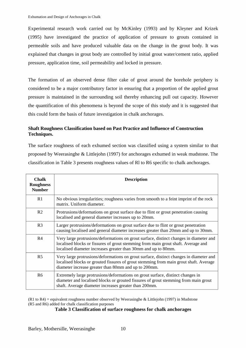
Shaft Roughness Classification based on Past Practice and Influence of Construction Techniques. The surface roughness of each exhumed section was classified using a system similar to that
proposed by Weerasinghe & Littlejohn (1997) for anchorages exhumed in weak mudstone. The
classification in Table 3 presents roughness values of Rl to R6 specific to chalk anchorages.
Chalk
Roughness Number
Description
R1 No obvious irregularities; roughness varies from smooth to a feint imprint of the rock matrix. Uniform diameter.
R2 Protrusions/deformations on grout surface due to flint or grout penetration causing localised and general diameter increases up to 20mm.
R3 Larger protrusions/deformations on grout surface due to flint or grout penetration causing localised and general diameter increases greater than 20mm and up to 30mm.
R4 Very large protrusions/deformations on grout surface, distinct changes in diameter and localised blocks or fissures of grout stemming from main grout shaft. Average and localised diameter increases greater than 30mm and up to 80mm.
R5 Very large protrusions/deformations on grout surface, distinct changes in diameter and localised blocks or grouted fissures of grout stemming from main grout shaft. Average diameter increase greater than 80mm and up to 200mm.
R6 Extremely large protrusions/deformations on grout surface, distinct changes in diameter and localised blocks or grouted fissures of grout stemming from main grout shaft. Average diameter increases greater than 200mm.
(R1 to R4) = equivalent roughness number observed by Weerasinghe & Littlejohn (1997) in Mudstone (R5 and R6) added for chalk classification purposes
Table 3 Classification of surface roughness for chalk anchorages
Exhumation and Design of Anchorages in Chalk
Barley, Mothersille, Weerasinghe 11
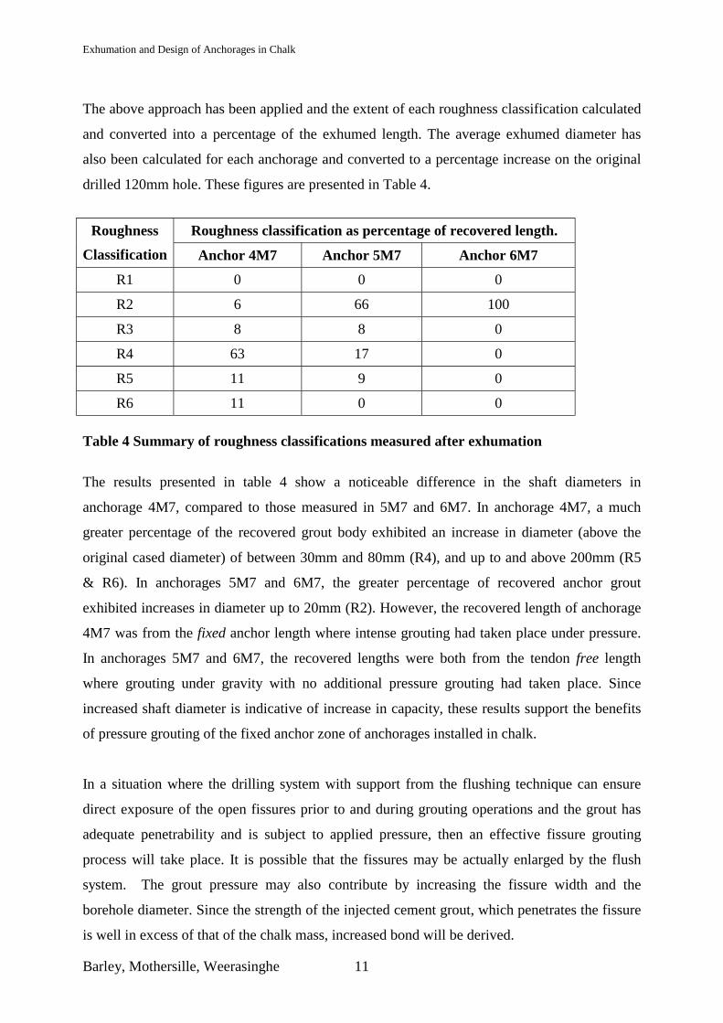
The above approach has been applied and the extent of each roughness classification calculated
and converted into a percentage of the exhumed length. The average exhumed diameter has
also been calculated for each anchorage and converted to a percentage increase on the original
drilled 120mm hole. These figures are presented in Table 4.
Roughness classification as percentage of recovered length. Roughness
Classification Anchor 4M7 Anchor 5M7 Anchor 6M7
R1 0 0 0
R2 6 66 100
R3 8 8 0
R4 63 17 0
R5 11 9 0
R6 11 0 0 Table 4 Summary of roughness classifications measured after exhumation
The results presented in table 4 show a noticeable difference in the shaft diameters in
anchorage 4M7, compared to those measured in 5M7 and 6M7. In anchorage 4M7, a much
greater percentage of the recovered grout body exhibited an increase in diameter (above the
original cased diameter) of between 30mm and 80mm (R4), and up to and above 200mm (R5
& R6). In anchorages 5M7 and 6M7, the greater percentage of recovered anchor grout
exhibited increases in diameter up to 20mm (R2). However, the recovered length of anchorage
4M7 was from the fixed anchor length where intense grouting had taken place under pressure.
In anchorages 5M7 and 6M7, the recovered lengths were both from the tendon free length
where grouting under gravity with no additional pressure grouting had taken place. Since
increased shaft diameter is indicative of increase in capacity, these results support the benefits
of pressure grouting of the fixed anchor zone of anchorages installed in chalk.
In a situation where the drilling system with support from the flushing technique can ensure
direct exposure of the open fissures prior to and during grouting operations and the grout has
adequate penetrability and is subject to applied pressure, then an effective fissure grouting
process will take place. It is possible that the fissures may be actually enlarged by the flush
system. The grout pressure may also contribute by increasing the fissure width and the
borehole diameter. Since the strength of the injected cement grout, which penetrates the fissure
is well in excess of that of the chalk mass, increased bond will be derived.
Exhumation and Design of Anchorages in Chalk
Barley, Mothersille, Weerasinghe 12
However there are drilling and grouting or concreting systems carried out in chalks that may
not offer such benefits -
• auguring, which smears the entrance to chalk fissures that intersect the borehole
• the use of a “grout” (or concrete) which will not adequately penetrate the fissures
• the use of a grouting method that does not ensure some fissure penetration .
In such circumstances there is no or little enhancement from the shear of the grout and the
capacity is only available from chalk/grout bond or from smeared chalk to grout bond.
This is consistent with observation of anchor grout bodies exhumed from weak mudstones.
Here the grain structure is finer, there are no flints or cavities in the rock matrix and no
pressure grouting was applied, Weerasinghe and Littlejohn (1997) observed no obvious
irregularities in the fixed anchor surface. The exhumed anchorages were found to exhibit a fine
imprint of the rock and diametric variations were generally below 10mm (R2); the exhumed
diameters varied between -8% (reduced) and + 11 % of the original shaft diameter.
In chalk anchorages where grout take of fissures and voids may be high there is effectively a
balance between the volume of grout which penetrates the chalk mass (associated with the
enhancement of the anchor capacity), and the volume of grout which travels away from the
anchor bore and is associated with ground improvement. The balance between these volumes is
difficult to achieve. For a contract measurement guideline BS8081:1989 advises that in
addition to the grouting of the drilled borehole, a supplementary grout volume of twice the
borehole volume may be associated with ground strengthening adjacent to the bore to provide
this enhancement in anchor capacity i.e. a total grout take of three times the volume of the
fixed length bore. At Castle Mall total grout takes, even utilising stiff sanded mix, were
considerably higher.
The Integrity of the Corrosion Protection System in Exhumed Anchor Bodies The integrity of the corrosion protection applied to any anchor of permanent or semi permanent
usage is critical to the success of the performance of the anchor (European Standard
EN1537:2000).
At Castle Mall, although the anchors were in principle “temporary” it was considered that there
was a possibility of construction interruption such that the anchor support may be required for
Exhumation and Design of Anchorages in Chalk
Barley, Mothersille, Weerasinghe 13
a lengthy period. Such occurrences due to change of ownership or financial difficulties have
unfortunately been encountered on other deep basement sites. The production anchors were
therefore required to be double protected whilst test anchors were required to be single
protected. This would allow two strands to be installed in each unit SBMA encapsulations in
lieu of one, resulting in the testing to a much higher load, particularly appropriate in trial
anchor works.
Free length protection consisted of a greased strand surrounded by a 1mm thick close fitting
plastic sheath, then contained within a loose fitting plastic sheath (often considered to be
sacrificial). Damage to this loose fitting sheath was apparent but generally attributable to the
excavator works during exhumation and anchor body withdrawal. There was however no
evidence of the perforation or splitting of the tight fitting sheath around the individual strands.
The bond lengths of the unit anchors were contained and grouted within a 50mm diameter
corrugated plastic duct of the form generally used in the anchor industry. Close inspection
revealed that where ducts were contained within the grout bodies, undamaged by exhumation,
the ducts were fully intact with no cracks to allow entry of corrosive elements (Plate16).
THE CONSTRUCTED ANCHOR BODY AND SHORT LENGTH LOAD TRANSFER MECHANISM The photographs of the exhumed anchorages highlight the distribution of grout, despatched
under pressure, from the anchor bore into the chalk mass to form a black irregular “skeleton”
of grout within the chalk mass itself; this grout being many times greater in strength than that
of the chalk material.
Over a one metre length of bore it is reasonable to assume that the elasticity of the anchor
tendon and the progressive debonding mechanism does not influence pull out, i.e. the tendon
and grout body move as one unit within the chalk mass. Thus, for this one metre long
cylindrical body to pull-out from the chalk mass the following must occur:
1. failure of bond over the area of the grout/chalk interface approximately to the original
bore and
2. failure of the grout in shear at the intersection of the grouted fissures within the failure
cylinder or
3. failure at chalk/chalk and/or grout/chalk interface along a larger diameter irregular
cylindrical shape than the original bore
Failure mechanisms (1) and (2) along a cylindrical failure plane are presented in Figure 5 (a).
The surface area of the cylindrical failure plane has been projected in order to illustrate the area
Exhumation and Design of Anchorages in Chalk
Barley, Mothersille, Weerasinghe 14
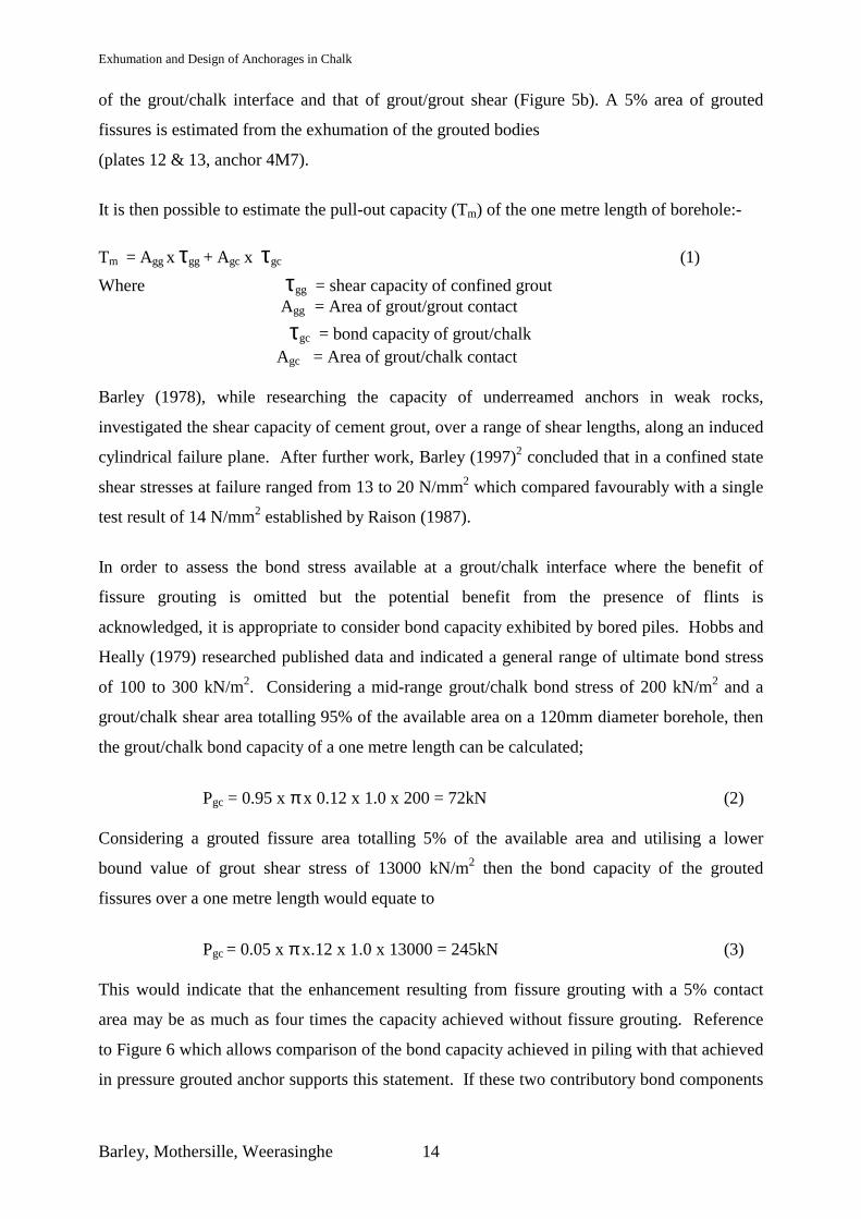
of the grout/chalk interface and that of grout/grout shear (Figure 5b). A 5% area of grouted
fissures is estimated from the exhumation of the grouted bodies
(plates 12 & 13, anchor 4M7).
It is then possible to estimate the pull-out capacity (Tm) of the one metre length of borehole:- Tm = Agg x τgg + Agc x τgc (1) Where τgg = shear capacity of confined grout
Agg = Area of grout/grout contact τgc = bond capacity of grout/chalk Agc = Area of grout/chalk contact Barley (1978), while researching the capacity of underreamed anchors in weak rocks,
investigated the shear capacity of cement grout, over a range of shear lengths, along an induced
cylindrical failure plane. After further work, Barley (1997)2 concluded that in a confined state
shear stresses at failure ranged from 13 to 20 N/mm2 which compared favourably with a single
test result of 14 N/mm2 established by Raison (1987).
In order to assess the bond stress available at a grout/chalk interface where the benefit of
fissure grouting is omitted but the potential benefit from the presence of flints is
acknowledged, it is appropriate to consider bond capacity exhibited by bored piles. Hobbs and
Heally (1979) researched published data and indicated a general range of ultimate bond stress
of 100 to 300 kN/m2. Considering a mid-range grout/chalk bond stress of 200 kN/m2 and a
grout/chalk shear area totalling 95% of the available area on a 120mm diameter borehole, then
the grout/chalk bond capacity of a one metre length can be calculated;
Pgc = 0.95 x π x 0.12 x 1.0 x 200 = 72kN (2)
Considering a grouted fissure area totalling 5% of the available area and utilising a lower
bound value of grout shear stress of 13000 kN/m2 then the bond capacity of the grouted
fissures over a one metre length would equate to
Pgc = 0.05 x π x.12 x 1.0 x 13000 = 245kN (3)
This would indicate that the enhancement resulting from fissure grouting with a 5% contact
area may be as much as four times the capacity achieved without fissure grouting. Reference
to Figure 6 which allows comparison of the bond capacity achieved in piling with that achieved
in pressure grouted anchor supports this statement. If these two contributory bond components
Exhumation and Design of Anchorages in Chalk
Barley, Mothersille, Weerasinghe 15
are then considered together, the overall bond stress, averaged over a metre length at failure
would be
τ = 72 + 245 = 840 kN/m2 (4) π x 0.12 x 1.0 This design approach, evolved from Castle Mall exhumation, is supported by the results
achieved over short fixed length tests. Several pull out tests on 2m fixed lengths exhibited bond
stress values of 849 kN/m², some without failure (Table 2).
However there is the potential alternative failure mechanism 3 (Figure 5a) in which pull-out of
a large diameter cylinder containing grouted fissures and voids could occur. When a failure
bond stress of 840 kN/m² is mobilised along the 120mm diameter grouted bore then a bond
stress of 200 kN/m² is being mobilised at the grout/chalk interface on a 500mm diameter
cylinder. Exhumation of pressure grouted fixed anchors did suggest that such overall diameters
of grout and grouted bulbs did exist.
PROGRESSIVE DEBONDING, EFFICIENCY FACTORS AND ANCHOR DESIGN When considering long fixed lengths it is fully acknowledged by numerous researchers who
have investigated the load transfer from anchor tendon to the ground via grout, that the
distribution of stress along fixed lengths greater than one or two metres is non-uniform. This
results from the general incompatibility between the elastic modulus of the anchor tendon, of
the anchor grout and of the grouted ground. Typically, an anchor tendon with a 6m fixed
length will at proof load need to extend some 15 to 20mm at the proximal end of the fixed
length before any load will be transferred by the tendon to the distal end.
Thus, in the vast majority of anchors, when applying the initial load, the bond stress is
concentrated over the proximal length of the fixed anchor and at that time the distal component
of the fixed anchor is unstressed and redundant. As load is increased in the anchor, the
ultimate bond stress at either (or both) the tendon grout and grout ground interface (chalk) is
exceeded. After interfacial movement the residual bond stress at that location is generally of a
lower order. For example Weerasinghe and Littlejohn (1997) report ultimate bond stresses in
mudstone of 520kN/m2 and residual bond stresses of 425kN/m2.
Exhumation and Design of Anchorages in Chalk
Barley, Mothersille, Weerasinghe 16
As load in the overall anchor is further increased the bond stress concentration zone progresses
further along the fixed anchor. Prior to failure of the anchor the load concentration zone
approaches the distal end of the anchor. Figure 7a typifies the distribution of bond stress along
a normal fixed anchor during initial loading and when approaching failure, albeit the
relationship between the ultimate bond stress and the residual bond stress will vary with
ground conditions and grouting techniques.
Barley (1990) demonstrated qualitatively how anchorages in chalk (and other soils) much
potential bond capacity was lost before failure as a consequence of progressive load transfer.
In 1995 Barley compared the ultimate tensile capacity of anchorages of the same diameter but
with different fixed lengths; generally in stiff to very stiff clayey soils. Based on this data and
with consideration of the Norwich chalk test anchorage which also investigated anchor
capacities with different fixed lengths Barley introduced an efficiency factor, itself a function
of the fixed anchor length L, to take account of the occurrence of progressive debonding such
that the ultimate anchor load Tult is given by:
Tult = τavg x π x D x L
and τ avg = feff xτult
Tult = Ultimate load (kN)
D = borehole diameter (m)
L = fixed length (m)
τult = ultimate bond stress over a short fixed length (kN/m²)
τ avg = average value of ultimate bond stress over a long length (kN/m²)
By normalising the results from anchors of different lengths in clayey soils Barley (1995)
empirically obtained:
feff = 1.6 L – 0.57
From Figure 8 it may be seen that an anchor 2.3m long would have an efficiency factor of
100%. If such an anchor developed an ultimate bond stress τ ult, then for a fixed anchor of
length L
(τ avg)L = 1.6 L –0.57 x τ ult
Exhumation and Design of Anchorages in Chalk
Barley, Mothersille, Weerasinghe 17
If an ultimate average bond stress of (τavg)l was measured on a trial anchor of fixed length l it
can be shown that for a longer contract anchor of length L the ultimate average bond stress is
given by:
(τ avg)l = (1/L)0.57 (τ avg)L
Thus an 8m long fixed anchor would be expected to develop an ultimate average bond stress
which was 67% of that for a 4m long fixed anchor.
Barley and Windsor (2000) reported on the investigation of the validity of the use of the value
of the efficiency factor in a wide range of soils. They concluded that the curve defined by
1.6L-0.57 when imposed on similar graphical plots (defining reduction in bond stress with
increase in fixed length) closely reflected the boundaries selected by Ostermayer (1974) in his
extensive studies. This applied to anchors founded in stiff to very stiff clays, postgrouted or
non-postgrouted and in sands and sandy gravels. Anchors founded in chalk which achieve
grout penetration of open discontinuities may compare closely in finished form with post
grouted anchors in clay or with pressure grouted anchors in gravels. On that basis Barley and
Windsor suggested that provided the design formulae for fixed anchors in soils and weak rocks
always incorporate an efficiency factor, test anchors 2.5 to 5m in length may easily be taken to
failure to establish the average bond stress of that length, and then the fixed length of
production anchorages may be accurately designed to provide the required factor of safety
using the relationship between (τavg)l and (τavg)L given above.
In the modern application of this principle to Castle Mall Test Anchors, a 2m fixed anchor with
an ultimate bond capacity of 840 kN/m² would provide a production anchor design for a
normal 8m fixed length with an average bond capacity at failure load of 411 kN/m². Employing
a factor of safety of 2.5 the maximum working load would be 496 kN.
Exhumation and Design of Anchorages in Chalk
Barley, Mothersille, Weerasinghe 18
THE SINGLE BORE MULTIPLE ANCHOR It was realised in the late 1970’s but not developed until the late 1980’s that the combination of
a number of “unit” anchors, each with a short fixed anchor length, could be founded at
staggered depths in a single borehole and provide an exceptionally high capacity multiple
anchor (Barley et al 1992, Barley 1995). It was this development and research work that
allowed evolution of the efficiency factor concept (Figure 8) and a design formula that
accommodated the progressive debonding phenomenon.
The method of calculation of capacity of short fixed anchors is summarised above. The
ultimate capacity of a multiple of short “unit” anchors, the lengths of which themselves may
vary (2.5 to 4m generally) is the summation of the capacity of each unit
i.e. SBMA capacity = ∑ Tult (of a multiple of units) = π x D x L1 x feff x τult + π x D x L2 x feff xτult + ……+ π x D x Ln x feff xτult The comparison of capacity of an SBMA with a conventional anchor is best illustrated in
Figure 7b: the shaded area under the lines equating to the anchor capacity. Hence the efficiency
of ground strength mobilisation of a multiple of short anchors, say 4 x 2.5m units, is in the
order of twice that of a normal 10m long fixed anchor. Furthermore for each additional unit
anchor added beyond 10m (generally up to 7 in total) the SBMA capacity increases
proportionally. Hence with efficient multiple fixed lengths up to 25m, capacities of up to 3
times that of normal anchors may be achieved. The system is particularly suited to soils and
weak rocks such as chalk. The 800 chalk anchors installed at the Castle Mall site utilised this
system and encountered no failures. Based on bond capacities previously demonstrated in
grades 2 to 3 Chalk and application of the multiple anchor design principles, chalk anchor
working capacities of up to 3000 kN have recently been proposed.
Exhumation and Design of Anchorages in Chalk
Barley, Mothersille, Weerasinghe 19
CONCLUSIONS
1. The installation, testing and subsequent exhumation of trial anchors, founded in
fissured chalk using end of casing pressure grouting techniques, has allowed
considerable advancement in the understanding of load transfer in chalk anchors.
Gravity pregrouting of chalk cavities and wide fissures using a sanded mix stemmed the
unnecessary flow of grout away from the bore. Subsequent pressure grouting with a
neat grout resulted in the local grout penetration of fine but irregular fissures which
were clearly observed on removal of the grouted anchor bodies from the chalk mass.
2. Pressure application on the neat grout also resulted in the forced filtration of water from
grout into the chalk matrix leaving a dark dense annulus of grout up to 20 mm thick
around the grouted bore. Such observations are comparable to the characteristics
identified in exhumed injection anchors founded in fine granular material.
3. After removal of the chalk matrix from within the skeletal formation of grouted fissures
two potential modes of load transfer from the grout body to the chalk are evident. The
necessary shearing of the grout in the fissures prior to pull-out failure would provide a
shear resistance of an order of magnitude greater than the grout/chalk bond resistance.
Such fissure penetration is considered to be the major contributory factor in chalk
injection anchors which allows mobilisation of average bond stresses of four times that
obtained in piling practice.
4. Based on an assumed grouted fissure profile adjacent to the anchor body (from
exhumation observations), and knowing from previous research the direct shear
capacity of grout, it is possible to assess the pull-out capacity per metre length of
grouted bore for design purposes.
5. Measurements of exhumed shaft diameters revealed that in the fixed anchor length
where pressure grouting was used during construction, over 85% of the recovered
length exhibited an increased diameter ranging from 30mm to in excess of 200mm (i.e.
expanding from 120 mm bore to a 180 to 520 mm anchor body). In the free length,
where the anchorage was grouted under gravity during construction, between 74% and
100% of the recovered length exhibited an increased diameter of less than 30mm. Since
increase in diameter is likely to result in an increase in capacity, it is concluded that
pressure grouting in the fixed anchor length is grossly beneficial to the enhancement of
capacity of anchorages in chalk.
Exhumation and Design of Anchorages in Chalk
Barley, Mothersille, Weerasinghe 20
6. Acknowledging that the anchor capacity in soils and weak rocks is not proportional to
the fixed anchor length, it is possible, using the recently developed “efficiency” factor
theory, to estimate the capacity of normal long fixed length anchor, or of the single bore
multiple anchor in which unit anchors utilise a multiple of short efficient fixed lengths.
Using the latter techniques some ten years of research and practice has demonstrated
ultimate anchor capacities of up to 5000kN. Working capacities of 2000 kN have been
satisfactorily achieved, complete with proof loading. Working capacities of 3000 kN
are currently proposed for multiple anchors founded in chalk.
7. Inspection of the tendons and encapsulation units over the fixed anchor length revealed
that the corrosion protection system in the individual unit anchors had remained fully
intact during anchor installation and during proof load testing to 2.4 times working
load.
Information from exhumation and anchor performance has provided a much improved
understanding of the benefits of appropriate methods of flushing and grouting, and of the
ensuing load transfer mechanisms, within the anchor body.
Exhumation and Design of Anchorages in Chalk
Barley, Mothersille, Weerasinghe 21
ACKNOWLEDGEMENTS The authors wish to thank the following for the provision of valuable data without which this paper could not have been presented: Client: Estates and General plc and Friends Provident Consulting Engineer: Ove Arup and Partners Management Contractor: Bovis Construction Ltd Ground Anchorage Contractor: Keller Colcrete Ltd Exhumation Monitoring: University of Bradford REFERENCES Barley A.D. (1978), “A Study and Investigation of underreamed anchors and associated load transfer mechanisms”. Research Thesis, Marischal College, Aberdeen. Barley A.D. (1988) “Ten thousand Anchorages in rock” Ground Engineering, Sept,Oct,Nov 1998. Barley A.D. (1990), ‘Contribution to discussion on underground excavations and slope stability in Chalk’, In: Chalk, Proc. Int. Chalk Sym, Brighton polytechnic, 1989, Thomas Telford, London. P552 Barley A.D., Eve R and Twine D (1992), ‘Design and Construction of Temporary Ground Anchors at castle Mall Developments’, Norwich. ICE Conference on Retaining Structures, Cambridge July 1992. Barley A.D. (1995), “Theory and Practice of The Single Bore Multiple Anchor System” Proc. of Int. Symposium on Anchors in Theory and Practice – Salzburg Austria, October. Barley A.D. (1997)1 “The effects of application of pressure in a ground anchor from inspection of exhumed grout bodies” Personnel correspondence. Barley A.D. (1997)2 “Properties of Anchor Grouts in a confined state” Proc. of Int. Conference on Ground Anchorages, ICE London. Barley A.D. and Windsor C (2000), “Recent advances in ground anchor technology with reference to the development of the art” Int. Conference on Geotechnical and Geological Engineering, Melbourne November. British Standard Code of Practice BS8081:1989 – Ground Anchorage, British Standard Institution, 1989. CIRIA (1994) “Foundations in Chalk”, CIRIA Project Report 11, Construction Industry Research and Information Association, London, 189pp
Exhumation and Design of Anchorages in Chalk
Barley, Mothersille, Weerasinghe 22
European Standard EN 1537:2000 The Execution of Special Geotechnical Work – Ground Anchors Grose W.J. and Toone B.H. (1992), “The Selection, design and performance of a multi-propped contiguous pile retaining wall in Norwich. Int. Conference on Retaining Structures, Cambridge July 1992. Hobbs N.B. and Heally R. (1979), “Piling in Chalk” CIRIA Publication. Kleyner and Krizek. (1995), “Mathematical Model For Bore-Injection Cement Grout Installations” Journal of Geotechnical Engineering, November Littlejohn, G.S. (1970), ‘Soil Anchors’ ICE Conference on Ground Engineering, June 1970. McKinley (1993), “Grouted ground anchors and the soil mechanics aspects of cement grouting” PhD Thesis, Cambridge, 1993. Newman T.G. and Ingle J.L.(2002), ‘A comparison between tube-a-manchette and lance grouting to assist tunnel excavation through chalk’, Proceedings of the Institution of Civil Engineers. Geotechnical Engineering 135 July 2002 Issue 3, pp.175-186 Ostermayer H. (1974), Construction Carrying Behaviour and Creep Characteristics of Ground Anchors. ICE Conference on Diaphragm Walls and Anchorages, London. Raison C.A. (1987), “Ground Anchorages: component testing at the British Library, Euston” Proceedings of Institution of Civil Engineers, Part 1, 1987, 82 Jan. pp 615-626 Ward, W.H., Burland, J.B. and Gallois, R.M (1968), “Geotechnical assessment of a site at Munford, Norfolk for a Proton Accelerator”, Geotechnique, 18(4) 399-431. Weerasinghe, R.B & Littlejohn, G.S. (1997), “Uplift capacity of shallow anchorages in weak mudstone” Proc. Int. Conf. On Ground Anchorages and Anchored Structures, ICE, London, 20-21 March 1997, pp.23 – 33.
Related Documents