26 EWJ / EW / SWJ / SW Series EWJ / EW SWJ / SW Series Model Number Designation ... 27 Shaft Arrangement ........... 28 Models ............................... 29 Motor Options ................... 29 Mounting Examples.......... 30 Motor and Reduction Ratio Combinations.................... 31 Sizing Chart ............... 32 - 34 Technical Data ........... 35 - 40 Actual Reduction Ratio Allowable Loads on Shafts Starting Efficiency Moment of Inertia on Input Shaft Internal Construction .... 41 - 44 Dimensional Drawings .. 45 - 74 Single Reduction Gear Reducers

Welcome message from author
This document is posted to help you gain knowledge. Please leave a comment to let me know what you think about it! Share it to your friends and learn new things together.
Transcript

26
EWJ
/ EW
/ SW
J / S
W S
erie
s
EWJ / EW SWJ / SW Series
Model Number Designation ... 27
Shaft Arrangement ........... 28
Models ............................... 29
Motor Options ................... 29
Mounting Examples .......... 30
Motor and Reduction Ratio Combinations.................... 31
Sizing Chart ............... 32 - 34
Technical Data ........... 35 - 40Actual Reduction Ratio Allowable Loads on Shafts Starting Efficiency Moment of Inertia on Input Shaft
Internal Construction .... 41 - 44
Dimensional Drawings .. 45 - 74
Single Reduction Gear Reducers
27
一段減速 (減速比1/10~1/60)Single Reduction Reducer (Reduction ratio 1/10 to 1/60)
Model Number DesignationSeries Size Mounting Position Reduction Ratio Shaft Arrangement Motor Capacity Motor Specifi cations Options
EWJEWJM
EWEWMSWJ
SWJMSW
SWMSeries
EWJ 25 E 10 L -T2
SWJ 50 E 20 DF
EW 100 B 30 R
SW 100 B 40 LF
EWJM 42 E 30 LR 040 S
SWJM 63 E 40 DF 075 S H-K
EWM 100 T 25 H 370 S
SWM 100 V 60 SRF 220 SB V
EWJ/SWJ
25/35/42
50/63/70
EWJM
42/50
63/70
SWJM
35/42/50
63/70
EW/SW
80/100
125/150
175/200
EWM/SWM
80/100
125/150
EWJ25 to 42
EWJM42
SWJ25 to 70
SWJM35 to 70
E: E type
EWJ50 to 70
EWJM50 to 70
E: E type
V: V type
EW/EWM
SW/SWM
80 to 200
T: T type
B: B type
V: V type
10: 1/10
15: 1/15
20: 1/20
25: 1/25
30: 1/30
40: 1/40
50: 1/50
60: 1/60
See Page
29
(3-phase)
010: 0.1 kW
020: 0.2 kW
040: 0.4 kW
075: 0.75 kW
150: 1.5 kW
220: 2.2 kW
370: 3.7 kW
550: 5.5 kW
S:Ship with standard
motormounted.
SB:Ship with standard
motor with brake
mounted.
SX:Ship with customer-supplied
motormounted.
Y:Customerto mount
motor
Reducer 1)
See pages
225 - 237
Motor 2)
See pages
238 - 239
Withoutmotor
Withmotor
Single Reduction Gear Reducers
Note 1) Enter a hyphen before the reducer option symbol. 2) Specify the motor option symbol after the motor instruction symbols "S" or "SB".
28
EWJ
/ EW
/ SW
J / S
W S
erie
sSi
ngle
Red
uctio
n Ge
ar R
educ
ers
Spec
ifi ca
tions
3Eつばきウォーム減速機Tsubaki Worm Gear Reducer Search
Sing
le R
educ
tion
Gear
Red
ucer
sSi
ze42
Sing
le R
educ
tion
Gear
Red
ucer
sSi
ze50
Sing
le R
educ
tion
Gear
Red
ucer
sSi
ze63
Sing
le R
educ
tion
Gear
Red
ucer
sSi
ze70
Sing
le R
educ
tion
Gear
Red
ucer
sSi
ze80
Sing
le R
educ
tion
Gear
Red
ucer
sSi
ze10
0
Sing
le R
educ
tion
Gear
Red
ucer
sSi
ze12
5
Sing
le R
educ
tion
Gear
Red
ucer
sSi
ze15
0
Sing
le R
educ
tion
Gear
Red
ucer
sSi
ze17
5
Sing
le R
educ
tion
Gear
Red
ucer
sSi
ze20
0
Single
Red
uctio
n Ge
ar Re
duce
rsSiz
e25/3
5
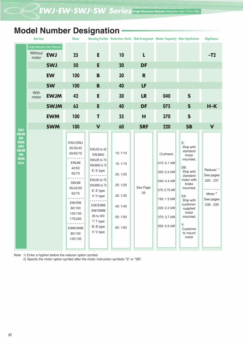
Shaft ArrangementArrows in fi gures indicate direction of rotation.
E typeE-L E-R E-LR
T type
T-L T-R T-LR T-H
B type
B-L B-R B-LR B-H
V typeV-LU V-LD V-LUD
V-RU V-RD V-RUDNote 1) E type applies to the EWJ series, and the hollow output shaft type (-H) applies to the EW series. 2) If the shaft type is double output, the keyway may not be in the same phase. Contact us if the phases must be matched.
Arrows in fi gures indicate direction of rotation.
E typeE-L E-R E-LR
T type
T-L T-R T-LR T-H
V typeV-LU V-LD V-LUD
V-RU V-RD V-RUDNote 1) E type applies to the EWJM series, and the hollow output shaft type (-H) applies to the EWM series. 2) If the shaft type is double output, the keyway may not be in the same phase. Contact us if the phases must be matched.
Arrows in fi gures indicate direction of rotation.
Without motor With motor
E type
E-DF E-DF
B type(E type)
B-LF(E-LF) B-RF(E-RF) B-SLF B-SRF B-LF(E-LF) B-RF(E-RF) B-SLF B-SRF
T type(E type)
T-LF(E-RF) T-RF(E-LF) T-SLF T-SRF T-LF(E-RF) T-RF(E-LF) T-SLF T-SRF
V type(E type)
V-LF(E-LF) V-RF(E-RF) V-SLF V-SRF V-LF(E-LF) V-RF(E-RF) V-SLF V-SRFNote 1) The solid output shaft type (-SLF, -SRF) applies to the SW/SWM series. Shaft arrangements for models SWJ25 to 63 and SWJM35 to 63 are E-DF. 2) If the shaft type is double output, the keyway may not be in the same phase. Contact us if the phases must be matched.
EWJ / EW Series
EWJM / EWM Series
SWJ / SW / SWJM / SWM Series
29
一段減速 (減速比1/10~1/60)Single Reduction Reducer (Reduction ratio 1/10 to 1/60)
Series EWJ SWJ EW SW EW SW EWJ/EW SW
Redu
cer O
ptio
ns
EWJ/SWJ EW/SW SWJ/SW SWJ/SWMounting Position E T B V E T, B, V E, T, B, V E, T, B, V
Shaft Arrangement Solid
out
put
LRLR
–LRLR
SLFSRF
LRLR
SLFSRF
LULD
LUDRURD
RUD
SLFSRF
Doubleinput shaft :
T2
Doubleinput shaft :
See page 228 for symbol.
– –
Hollo
w ou
tput
–DFLFRF
H LFRF H LF
RF – LFRF
POWER-LOCKspecifi cation: K
Taper bushingspecifi cation:
TB
With
out m
otor
EWJ/SWJ25 – – – – – – – – –EWJ/SWJ35 – – – – – – – – –EWJ/SWJ42 – – – – – – – – –EWJ/SWJ50 – – – – – – –EWJ/SWJ63 – – – – – – –EWJ/SWJ70 – – – – – –EW/SW80 – – –EW/SW100 – – –EW/SW125 – – –EW/SW150 – – –EW/SW175 – – – –EW/SW200 – – – –
With
mot
or
SWJM35 – – – – – – – – –EWJM/SWJM42 – – – – – – – – –EWJM/SWJM50 – – – – – – –EWJM/SWJM63 – – – – – – –EWJM/SWJM70 – – – – – –EWM/SWM80 – – –EWM/SWM100 – – –EWM/SWM125 – – –EWM/SWM150 – – –EWM/SWM175 – – – –EWM/SWM200 – – – –
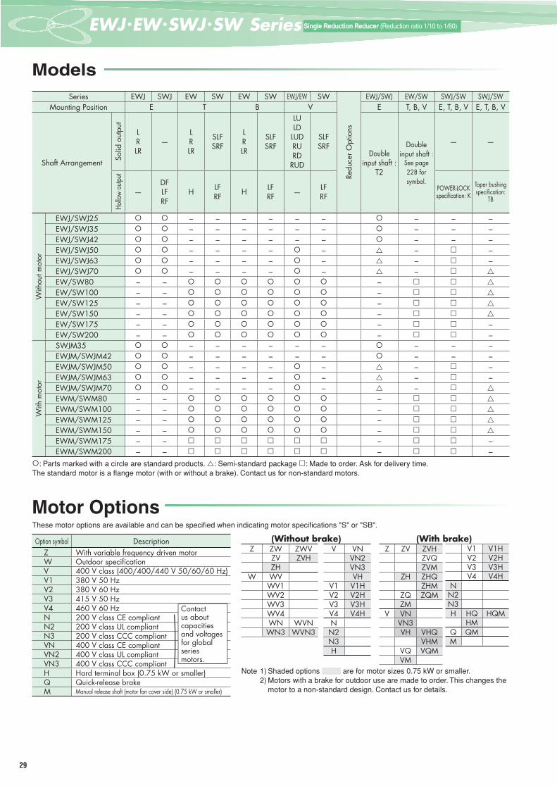
: Parts marked with a circle are standard products. : Semi-standard package : Made to order. Ask for delivery time.The standard motor is a fl ange motor (with or without a brake). Contact us for non-standard motors.
Models
Motor OptionsThese motor options are available and can be specifi ed when indicating motor specifi cations "S" or "SB".
Option symbol DescriptionZ With variable frequency driven motorW Outdoor specifi cationV 400 V class (400/400/440 V 50/60/60 Hz)V1 380 V 50 HzV2 380 V 60 HzV3 415 V 50 HzV4 460 V 60 HzN 200 V class CE compliantN2 200 V class UL compliantN3 200 V class CCC compliantVN 400 V class CE compliantVN2 400 V class UL compliantVN3 400 V class CCC compliantH Hard terminal box (0.75 kW or smaller)Q Quick-release brakeM Manual release shaft (motor fan cover side) (0.75 kW or smaller)
Note 1) Shaded options are for motor sizes 0.75 kW or smaller. 2) Motors with a brake for outdoor use are made to order. This changes the
motor to a non-standard design. Contact us for details.
Contactus about capacitiesand voltages for global seriesmotors.
)
Z ZW ZWVZV ZVHZH
W WVWV1WV2WV3WV4WN WVNWN3 WVN3
Z ZV ZVHZVQZVM
ZH ZHQZHM
ZQ ZQMZM
V VNVN3VH VHQ
VHMVQ VQMVM
V1 V1HV2 V2HV3 V3HV4 V4H
NN2N3H HQ HQM
HMQ QMM
(Without brake) (With brake)V VN
VN2VN3VH
V1 V1HV2 V2HV3 V3HV4 V4HNN2N3H

30
EWJ
/ EW
/ SW
J / S
W S
erie
sSi
ngle
Red
uctio
n Ge
ar R
educ
ers
Spec
ifi ca
tions
3Eつばきウォーム減速機Tsubaki Worm Gear Reducer Search
Sing
le R
educ
tion
Gear
Red
ucer
sSi
ze42
Sing
le R
educ
tion
Gear
Red
ucer
sSi
ze50
Sing
le R
educ
tion
Gear
Red
ucer
sSi
ze63
Sing
le R
educ
tion
Gear
Red
ucer
sSi
ze70
Sing
le R
educ
tion
Gear
Red
ucer
sSi
ze80
Sing
le R
educ
tion
Gear
Red
ucer
sSi
ze10
0
Sing
le R
educ
tion
Gear
Red
ucer
sSi
ze12
5
Sing
le R
educ
tion
Gear
Red
ucer
sSi
ze15
0
Sing
le R
educ
tion
Gear
Red
ucer
sSi
ze17
5
Sing
le R
educ
tion
Gear
Red
ucer
sSi
ze20
0
Single
Red
uctio
n Ge
ar Re
duce
rsSiz
e25/3
5
Mounting Examples
* EWJ/EWJM series may be mounted on any side.* Specify mounting position from examples 1 to 10 (shown below) when ordering models EW80 to 200 and EWM80 to 200 with standard
mounting.
EWJ / EW / EWJM / EWM Series
Installation direction T/B type Installation direction V type
Stan
dard
mou
ntin
gW
all m
ount
Example 1 Example 2 Example 3 Example 5 Example 7
Example 4 Example 6 Example 8
Cei
ling
mou
nt
Exam
ple
9
Exam
ple
10
Note) Contact us about the SW/SWM series.
Inpu
t hor
izon
tal,
outp
ut fa
ce u
p
Out
put h
oriz
onta
lIn
put f
ace
up
Out
put h
oriz
onta
lIn
put f
ace
up
Ou
tpu
t h
ori
zon
tal
on
botto
mIn
put h
oriz
onta
l on
top
Out
put h
oriz
onta
l on
top
Inpu
t hor
izon
tal o
n bo
ttom
Out
put h
oriz
onta
lIn
put f
ace
dow
n
Mount using top of housing.
Out
put h
oriz
onta
lIn
put f
ace
dow
n
Inpu
t hor
izon
tal,
outp
ut fa
ce d
own

31
一段減速 (減速比1/10~1/60)Single Reduction Reducer (Reduction ratio 1/10 to 1/60)
Motor and Reduction Ratio Combinations- Output torque values are for motor speeds of 1450 r/min, 1750 r/min (50/60 Hz).- Motor/reducer combinations shown are standard.- Shaded boxes indicate the motor capacity exceeds the allowable input kW of the reducer. Confi rm output torque before using. (Thermal
rating factor is 1.0)- Torque values may be lower if the ambient temperature is cold. Consult us for further details.- Refer to pages 21 to 22 for sizing.
0.2 kW 0.4 kW 0.75 kW 1.5 kW 2.2 kW 3.7 kW 5.5 kW
Size
Output torque
Size
Output torque
Size
Output torque
Size
Output torque
Size
Output torque
Size
Output torque
Size
Output torque50 Hz 60 Hz 50 Hz 60 Hz 50 Hz 60 Hz 50 Hz 60 Hz 50 Hz 60 Hz 50 Hz 60 Hz 50 Hz 60 Hz
N·m(kgf·m)
N·m(kgf·m)
N·m(kgf·m)
N·m(kgf·m)
N·m(kgf·m)
N·m(kgf·m)
N·m(kgf·m)
N·m(kgf·m)
N·m(kgf·m)
N·m(kgf·m)
N·m(kgf·m)
N·m(kgf·m)
N·m(kgf·m)
N·m(kgf·m)
10
Select from the Croise motor
series.
See Page 198
5044.0 37.0
6390 75
70132 110
80224 187
100337 281
(4.5) (3.8) (9.1) (7.6) (13.5) (11.2) (22.8) (19.1) (34.3) (28.6)
15 4232.2 27.0
5064.0 53.0
63129 108
70191 160
80325 272
100491 410
(3.3) (2.8) (6.5) (5.5) (13.2) (11.0) (19.4) (16.3) (33.1) (27.7) (50.1) (41.8)
20 4240.8 34.4
5083.0 69.0
63167 140
70247 207
80412 353
100637 533
(4.2) (3.5) (8.4) (7.1) (17.0) (14.3) (25.2) (21.1) (42.0) (36.0) (65.0) (54.4)
25 4249.2 41.5
50100 84.0
63196 171
80305 256
100525 440
125791 662
(5.0) (4.2) (10.2) (8.6) (20.0) (17.4) (31.2) (26.2) (53.6) (44.9) (80.7) (67.6)
30 4251.1 47.3
50103 95
63198 180
80350 295
100607 510
125916 770
(5.2) (4.8) (10.5) (9.7) (20.2) (18.4) (35.7) (30.1) (61.9) (52.1) (93.5) (78.5)
40 4234.1 29.0
5076 65.0
63145 123
80302 256
100457 386
125792 667
1501193 1003
(3.5) (3.0) (7.8) (6.6) (14.8) (12.6) (30.8) (26.1) (46.7) (39.4) (80.8) (68.0) (122) (102)
50 4240.0 34.2
5090 76
63174 147
80362 307
100552 467
125949 802
1501453 1225
(4.1) (3.5) (9.2) (7.8) (17.7) (15.0) (36.9) (31.3) (56.3) (47.6) (96.8) (81.8) (148) (125)
60 4245.2 38.8
5092 86
63177 163
80376 342
100628 543
1251017 931
1501561 1401
(4.6) (4.0) (9.4) (8.8) (18.1) (16.7) (38.4) (34.9) (64.1) (55.4) (104) (95.0) (159) (143)
0.2 kW 0.4 kW 0.75 kW 1.5 kW 2.2 kW 3.7 kW 5.5 kW
Size
Output torque
Size
Output torque
Size
Output torque
Size
Output torque
Size
Output torque
Size
Output torque
Size
Output torque50 Hz 60 Hz 50 Hz 60 Hz 50 Hz 60 Hz 50 Hz 60 Hz 50 Hz 60 Hz 50 Hz 60 Hz 50 Hz 60 Hz
N·m(kgf·m)
N·m(kgf·m)
N·m(kgf·m)
N·m(kgf·m)
N·m(kgf·m)
N·m(kgf·m)
N·m(kgf·m)
N·m(kgf·m)
N·m(kgf·m)
N·m(kgf·m)
N·m(kgf·m)
N·m(kgf·m)
N·m(kgf·m)
N·m(kgf·m)
10 3511.2 9.3
4222.5 18.8
5044 37
6390.0 75
70132 110
80224 187
100337 281
(1.1) (1.0) (2.3) (1.9) (4.5) (3.8) (9.1) (7.6) (13.5) (11.2) (22.8) (19.1) (34.4) (28.6)
15 3515.9 13.4
4232.2 27.0
5064 53
63129 108 *80
210 25080
325 272100
491 410(1.6) (1.4) (3.3) (2.8) (6.5) (5.5) (13.2) (11.0) (21.4) (25.5) (33.1) (27.7) (50.1) (41.8)
20 3520.1 16.9
4240.8 34.4
6383 70
70168 141
80250 210
80412 353
100637 533
(2.1) (1.7) (4.2) (3.5) (8.5) (7.1) (17.2) (14.4) (25.5) (21.4) (42.0) (36.0) (65.0) (54.4)
25 3524.2 20.4
4249.2 41.5
63102 85
70205 172
80305 256
100525 440
125791 662
(2.5) (2.1) (5.0) (4.2) (10.4) (8.7) (20.8) (17.6) (31.2) (26.2) (53.6) (44.9) (80.7) (67.6)
30 4228.0 23.7
5060 51
63115 98 *80
184 16580
350 295100
607 510125
916 770(2.9) (2.4) (6.6) (5.2) (11.8) (9.9) (18.8) (16.8) (35.7) (30.1) (61.9) (52.1) (93.5) (78.5)
40 4234.1 29.0
5076 65
63145 123
80302 256
100457 386
125792 667
1501193 1003
(3.5) (3.0) (7.8) (6.6) (14.8) (12.6) (30.8) (26.1) (46.7) (39.4) (80.8) (68.0) (122) (102)
50 4240.0 39.2
5086 76
63168 147
80362 307
100552 467
125949 802
1501453 1225
(4.1) (3.5) (8.8) (7.8) (17.1) (15.0) (36.9) (31.3) (56.3) (47.6) (96.8) (81.8) (145) (125)
60 4245.2 38.8
5086 80
70171 15.8
80376 342
100628 543
1251017 931
1501561 1401
(4.6) (4.0) (8.7) (8.2) (17.5) (16.2) (38.4) (34.9) (64.1) (55.4) (104) (95.0) (159) (143)* Consult us about non-standard combinations.
EWJM / EWM Series
SWJM / SWM Series
32
EWJ
/ EW
/ SW
J / S
W S
erie
sSi
ngle
Red
uctio
n Ge
ar R
educ
ers
Spec
ifi ca
tions
3Eつばきウォーム減速機Tsubaki Worm Gear Reducer Search
Sing
le R
educ
tion
Gear
Red
ucer
sSi
ze42
Sing
le R
educ
tion
Gear
Red
ucer
sSi
ze50
Sing
le R
educ
tion
Gear
Red
ucer
sSi
ze63
Sing
le R
educ
tion
Gear
Red
ucer
sSi
ze70
Sing
le R
educ
tion
Gear
Red
ucer
sSi
ze80
Sing
le R
educ
tion
Gear
Red
ucer
sSi
ze10
0
Sing
le R
educ
tion
Gear
Red
ucer
sSi
ze12
5
Sing
le R
educ
tion
Gear
Red
ucer
sSi
ze15
0
Sing
le R
educ
tion
Gear
Red
ucer
sSi
ze17
5
Sing
le R
educ
tion
Gear
Red
ucer
sSi
ze20
0
Single
Red
uctio
n Ge
ar Re
duce
rsSiz
e25/3
5
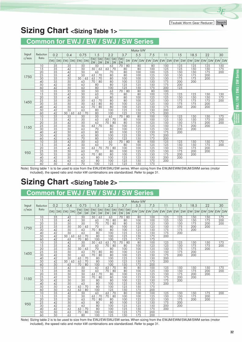
Sizing Chart <Sizing Table 1>
Common for EWJ / EW / SWJ / SW Series
Inputr/min
ReductionRatio
Motor kW0.2 0.4 0.75 1.5 2.2 3.7 5.5 7.5 11 15 18.5 22 30
EWJ SWJ EWJ SWJ EWJ SWJ EWJEW
SWJSW
EWJEW
SWJSW
EWJEW SW EW SW EW SW EW SW EW SW EW SW EW SW EW SW
1750
10 35 35 50 50 63 70 80 80 80 100 125 125 125 15015 35 42 50 50 63 63 70 80 80 100 125 125 150 150 17520 35 42 50 63 70 80 100 100 125 150 150 175 20025 35 42 50 63 70 80 80 100 125 150 150 175 20030 35 50 50 63 63 70 80 100 100 125 150 175 175 20040 35 50 63 70 80 80 100 125 150 175 200 20050 42 50 63 80 80 125 125 150 175 20060 42 50 63 80 100 125 150 175 200 125
1450
10 35 35 50 50 63 70 80 80 80 10015 35 42 50 63 70 80 80 100 125 125 125 150 15020 35 42 50 63 80 80 100 125 125 150 150 150 17525 35 50 50 63 70 80 80 100 125 150 175 175 175 20030 35 50 50 63 80 80 100 125 125 150 175 175 20040 42 50 63 70 80 80 100 125 150 175 200 200 20050 42 50 63 80 100 125 150 150 20060 42 50 63 63 70 80 100 125 150 175 200
1150
10 35 35 50 50 63 70 80 80 100 100 125 150 150 17515 35 42 50 63 63 70 80 100 100 125 150 150 175 20020 35 42 50 63 70 80 80 100 125 150 150 175 200 20025 35 50 50 63 70 80 100 125 125 150 175 200 20030 35 50 63 70 80 100 125 125 150 200 20040 42 50 63 80 80 100 125 150 175 20050 42 50 63 80 100 125 150 175 20060 42 63 70 80 100 125 150 175 200
950
10 35 42 50 63 63 70 80 80 100 125 125 150 150 17515 35 42 50 63 70 80 100 125 125 150 150 175 20020 35 42 50 63 70 70 80 100 100 125 150 150 175 20025 35 50 63 70 80 100 125 125 150 175 200 20030 35 50 63 70 80 80 100 125 150 175 200 20040 42 50 63 80 100 125 125 150 200 20050 42 63 63 80 100 125 150 175 20060 50 63 70 100 125 125 150 175
Note) Sizing table 1 is to be used to size from the EWJ/EW/SWJ/SW series. When sizing from the EWJM/EWM/SWJM/SWM series (motor included), the speed ratio and motor kW combinations are standardized. Refer to page 31.
Sizing Chart <Sizing Table 2>
Common for EWJ / EW / SWJ / SW Series
Inputr/min
ReductionRatio
Motor kW0.2 0.4 0.75 1.5 2.2 3.7 5.5 7.5 11 15 18.5 22 30
EWJ SWJ EWJ SWJ EWJEW
SWJSW
EWJEW
SWJSW
EWJEW
SWJSW
EWJEW
SWJSW EW SW EW SW EW SW EW SW EW SW EW SW EW SW
1750
10 35 42 50 50 63 63 70 80 80 100 125 125 150 150 17515 35 42 50 63 70 80 80 100 100 125 150 150 175 20020 35 50 50 70 70 80 80 100 125 150 150 175 200 20025 35 50 50 63 70 80 100 125 125 150 175 200 20030 42 50 63 70 80 80 100 125 150 175 175 20040 42 50 63 80 100 125 125 150 175 20050 42 50 63 63 70 80 100 125 150 175 20060 42 63 70 80 100 100 125 175 175
1450
10 35 42 50 50 63 63 70 70 80 80 100 125 125 150 150 17515 35 42 50 63 70 80 80 100 125 125 150 175 175 20020 35 50 50 63 70 80 100 100 125 150 175 175 20025 35 50 63 70 80 80 100 125 125 150 175 20030 42 50 63 70 80 80 100 125 150 175 200 20040 42 50 63 70 80 100 125 150 150 20050 42 50 63 63 70 80 100 125 150 175 20060 50 63 70 80 100 100 150 175 200
1150
10 35 42 50 63 63 70 80 80 100 125 150 150 150 17515 35 50 50 63 70 80 80 100 125 150 150 175 200 20020 35 50 50 63 70 80 100 125 125 150 175 200 20025 42 50 50 70 80 80 100 125 150 175 200 20030 42 50 50 80 80 100 125 150 175 20040 42 50 63 80 100 125 150 175 20050 50 63 63 70 80 100 125 150 17560 50 63 63 80 100 125 150 175 200
950
10 35 42 50 63 63 70 80 100 100 125 150 150 175 20015 35 50 50 63 70 70 80 100 100 125 150 150 175 20020 35 50 63 70 80 80 100 125 125 150 175 200 20025 42 50 63 80 80 100 125 150 175 20030 42 50 63 80 100 125 125 150 200 20040 42 63 63 70 80 100 125 150 175 20050 50 63 70 80 100 100 125 175 20060 50 63 80 100 125 150 175 200
Note) Sizing table 2 is to be used to size from the EWJ/EW/SWJ/SW series. When sizing from the EWJM/EWM/SWJM/SWM series (motor included), the speed ratio and motor kW combinations are standardized. Refer to page 31.
33
一段減速 (減速比1/10~1/60)Single Reduction Reducer (Reduction ratio 1/10 to 1/60)
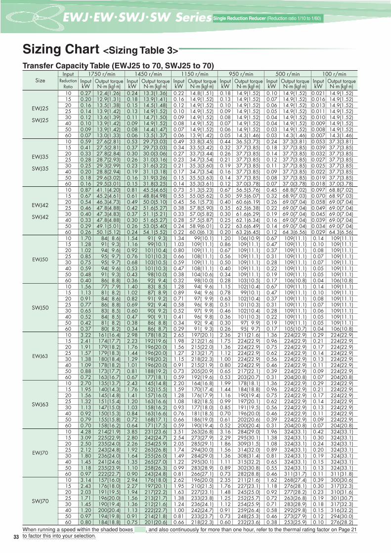
Sizing Chart <Sizing Table 3>
SizeInput 1750 r/min 1450 r/min 1150 r/min 950 r/min 500 r/min 100 r/min
ReductionRatio
Input Output torque Input Output torque Input Output torque Input Output torque Input Output torque Input Output torquekW N·m (kgf·m) kW N·m (kgf·m) kW N·m (kgf·m) kW N·m (kgf·m) kW N·m (kgf·m) kW N·m (kgf·m)
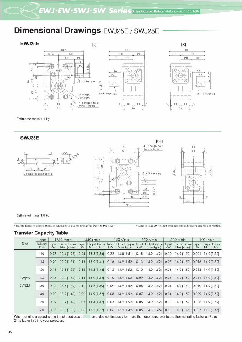
EWJ25
SWJ25
10 0.27 12.4 (1.26) 0.24 13.3 (1.36) 0.22 14.8 (1.51) 0.18 14.9 (1.52) 0.10 14.9 (1.52) 0.021 14.9 (1.52)15 0.20 12.9 (1.31) 0.18 13.9 (1.41) 0.16 14.9 (1.52) 0.13 14.9 (1.52) 0.07 14.9 (1.52) 0.016 14.9 (1.52)20 0.16 13.5 (1.38) 0.15 14.5 (1.48) 0.12 14.9 (1.52) 0.10 14.9 (1.52) 0.06 14.9 (1.52) 0.013 14.9 (1.52)25 0.14 13.9 (1.42) 0.13 14.9 (1.52) 0.10 14.9 (1.52) 0.09 14.9 (1.52) 0.05 14.9 (1.52) 0.011 14.9 (1.52)30 0.12 13.6 (1.39) 0.11 14.7 (1.50) 0.09 14.9 (1.52) 0.08 14.9 (1.52) 0.04 14.9 (1.52) 0.010 14.9 (1.52)40 0.10 13.9 (1.42) 0.09 14.9 (1.52) 0.08 14.9 (1.52) 0.07 14.9 (1.52) 0.04 14.9 (1.52) 0.009 14.9 (1.52)50 0.09 13.9 (1.42) 0.08 14.4 (1.47) 0.07 14.9 (1.52) 0.06 14.9 (1.52) 0.03 14.9 (1.52) 0.008 14.9 (1.52)60 0.07 13.0 (1.33) 0.06 13.5 (1.37) 0.06 13.9 (1.42) 0.05 14.3 (1.46) 0.03 14.3 (1.46) 0.007 14.3 (1.46)
EWJ35
SWJ35
10 0.59 27.6 (2.81) 0.53 29.7 (3.03) 0.49 33.8 (3.45) 0.44 36.5 (3.73) 0.24 37.3 (3.81) 0.053 37.3 (3.81)15 0.41 27.5 (2.81) 0.37 29.7 (3.03) 0.34 33.5 (3.42) 0.32 37.7 (3.85) 0.18 37.7 (3.85) 0.039 37.7 (3.85)20 0.33 27.8 (2.84) 0.30 30.0 (3.06) 0.27 33.7 (3.44) 0.26 37.7 (3.85) 0.14 37.7 (3.85) 0.032 37.7 (3.85)25 0.28 28.7 (2.93) 0.26 31.0 (3.16) 0.23 34.7 (3.54) 0.21 37.7 (3.85) 0.12 37.7 (3.85) 0.027 37.7 (3.85)30 0.25 29.3 (2.99) 0.23 31.6 (3.22) 0.21 35.3 (3.60) 0.19 37.7 (3.85) 0.11 37.7 (3.85) 0.025 37.7 (3.85)40 0.20 28.8 (2.94) 0.19 31.1 (3.18) 0.17 34.7 (3.54) 0.16 37.7 (3.85) 0.09 37.7 (3.85) 0.022 37.7 (3.85)50 0.18 29.6 (3.02) 0.16 31.9 (3.26) 0.15 35.5 (3.63) 0.14 37.7 (3.85) 0.08 37.7 (3.85) 0.019 37.7 (3.85)60 0.16 29.5 (3.01) 0.15 31.8 (3.25) 0.14 35.3 (3.61) 0.12 37.0 (3.78) 0.07 37.0 (3.78) 0.018 37.0 (3.78)
EWJ42
SWJ42
10 0.87 41.1 (4.20) 0.81 45.5 (4.65) 0.73 51.3 (5.23) 0.67 56.5 (5.76) 0.45 68.8 (7.02) 0.097 68.8 (7.02)15 0.67 45.2 (4.61) 0.61 48.8 (4.98) 0.55 55.0 (5.62) 0.50 59.5 (6.07) 0.32 68.9 (7.03) 0.070 68.9 (7.03)20 0.54 46.3 (4.73) 0.49 50.0 (5.10) 0.45 56.1 (5.73) 0.40 60.6 (6.19) 0.26 69.0 (7.04) 0.058 69.0 (7.04)25 0.46 47.8 (4.88) 0.42 51.6 (5.27) 0.38 57.8 (5.90) 0.35 62.5 (6.38) 0.22 69.0 (7.04) 0.049 69.0 (7.04)30 0.40 47.3 (4.83) 0.37 51.1 (5.21) 0.33 57.0 (5.82) 0.30 61.6 (6.29) 0.19 69.0 (7.04) 0.045 69.0 (7.04)40 0.33 47.8 (4.88) 0.30 51.6 (5.27) 0.28 57.5 (5.87) 0.25 62.1 (6.34) 0.16 69.0 (7.04) 0.039 69.0 (7.04)50 0.29 49.1 (5.01) 0.26 53.0 (5.40) 0.24 58.9 (6.01) 0.22 63.6 (6.49) 0.14 69.0 (7.04) 0.034 69.0 (7.04)60 0.26 50.1 (5.12) 0.24 54.1 (5.52) 0.22 60.0 (6.13) 0.20 63.2 (6.45) 0.12 64.3 (6.56) 0.029 64.3 (6.56)
EWJ50
10 1.70 84( 8.6) 1.54 91( 9.3) 1.34 99(10.1) 1.20 106(10.9) 0.67 109(11.1) 0.14 109(11.1)15 1.28 91( 9.3) 1.16 99(10.1) 1.03 109(11.1) 0.86 109(11.1) 0.47 109(11.1) 0.10 109(11.1)20 1.02 94( 9.6) 0.92 101(10.4) 0.80 109(11.1) 0.67 109(11.1) 0.37 109(11.1) 0.08 109(11.1)25 0.85 95( 9.7) 0.76 101(10.3) 0.66 108(11.1) 0.56 109(11.1) 0.31 109(11.1) 0.07 109(11.1)30 0.75 95( 9.7) 0.68 103(10.5) 0.59 109(11.1) 0.50 109(11.1) 0.28 109(11.1) 0.07 109(11.1)40 0.59 94( 9.6) 0.53 101(10.3) 0.47 108(11.1) 0.40 109(11.1) 0.22 109(11.1) 0.05 109(11.1)50 0.48 91( 9.3) 0.43 98(10.0) 0.38 104(10.6) 0.34 109(11.1) 0.19 109(11.1) 0.05 109(11.1)60 0.40 86( 8.8) 0.36 92( 9.4) 0.32 98(10.0) 0.28 103(10.5) 0.17 106(10.8) 0.04 106(10.8)
SWJ50
10 1.56 77( 7.9) 1.40 83( 8.5) 1.28 94( 9.6) 1.15 102(10.4) 0.67 109(11.1) 0.14 109 (11.1)15 1.13 81( 8.2) 1.02 87( 8.9) 0.89 94( 9.6) 0.78 99(10.1) 0.47 109(11.1) 0.10 109 (11.1)20 0.91 84( 8.6) 0.82 91( 9.2) 0.71 97( 9.9) 0.63 102(10.4) 0.37 109(11.1) 0.08 109 (11.1)25 0.77 86( 8.8) 0.69 92( 9.4) 0.58 96( 9.8) 0.51 101(10.3) 0.31 109(11.1) 0.07 109 (11.1)30 0.65 83( 8.5) 0.60 90( 9.2) 0.52 97( 9.9) 0.46 102(10.4) 0.28 109(11.1) 0.06 109 (11.1)40 0.52 84( 8.5) 0.47 90( 9.1) 0.41 96( 9.8) 0.36 101(10.3) 0.22 109(11.1) 0.05 109 (11.1)50 0.42 81( 8.2) 0.38 86( 8.8) 0.34 92( 9.4) 0.30 97( 9.9) 0.19 109(11.1) 0.05 109 (11.1)60 0.37 80( 8.2) 0.34 86( 8.7) 0.29 91( 9.3) 0.26 95( 9.7) 0.17 105(10.7) 0.04 106 (10.8)
EWJ63
10 3.22 161(16.4) 2.98 178(18.2) 2.65 197(20.1) 2.36 211(21.6) 1.36 224(22.9) 0.29 224(22.9)15 2.41 174(17.7) 2.23 192(19.6) 1.98 212(21.6) 1.75 224(22.9) 0.96 224(22.9) 0.21 224(22.9)20 1.91 179(18.2) 1.76 196(20.0) 1.56 215(22.0) 1.36 224(22.9) 0.75 224(22.9) 0.17 224(22.9)25 1.57 179(18.3) 1.44 196(20.0) 1.27 213(21.7) 1.12 224(22.9) 0.62 224(22.9) 0.14 224(22.9)30 1.38 180(18.4) 1.29 198(20.2) 1.15 218(22.3) 1.00 224(22.9) 0.56 224(22.9) 0.13 224(22.9)40 1.09 178(18.2) 1.01 196(20.0) 0.91 215(21.9) 0.80 224(22.9) 0.46 224(22.9) 0.11 224(22.9)50 0.88 173(17.7) 0.81 188(19.2) 0.73 205(20.9) 0.65 217(22.1) 0.39 224(22.9) 0.09 224(22.9)60 0.72 163(16.7) 0.67 177(18.1) 0.59 192(19.6) 0.53 203(20.7) 0.31 204(20.8) 0.07 204(20.8)
SWJ63
10 2.70 135(13.7) 2.43 145(14.8) 2.20 164(16.8) 1.99 178(18.1) 1.36 224(22.9) 0.29 224(22.9) 15 1.95 140(14.3) 1.76 152(15.5) 1.59 170(17.4) 1.44 184(18.8) 0.96 224(22.9) 0.21 224(22.9) 20 1.56 145(14.8) 1.41 157(16.0) 1.28 176(17.9) 1.16 190(19.4) 0.75 224(22.9) 0.17 224(22.9) 25 1.32 151(15.4) 1.20 163(16.6) 1.08 182(18.5) 0.99 197(20.1) 0.62 224(22.9) 0.14 224(22.9) 30 1.13 147(15.0) 1.03 158(16.2) 0.93 177(18.0) 0.85 191(19.5) 0.56 224(22.9) 0.13 224(22.9) 40 0.92 150(15.3) 0.84 163(16.6) 0.76 181(18.5) 0.70 196(20.0) 0.46 224(22.9) 0.11 224(22.9) 50 0.79 155(15.8) 0.72 168(17.1) 0.66 186(19.0) 0.61 202(20.6) 0.39 224(22.9) 0.09 224(22.9) 60 0.70 158(16.2) 0.64 171(17.5) 0.59 190(19.4) 0.52 200(20.4) 0.31 204(20.8) 0.07 204(20.8)
EWJ70
10 4.28 214(21.9) 3.85 231(23.6) 3.51 263(26.8) 3.16 284(29.0) 1.96 324(33.1) 0.42 324(33.1)15 3.09 225(22.9) 2.80 242(24.7) 2.54 273(27.9) 2.29 295(30.1) 1.38 324(33.1) 0.30 324(33.1)20 2.50 235(24.0) 2.26 254(25.9) 2.05 285(29.1) 1.86 309(31.5) 1.08 324(33.1) 0.24 324(33.1)25 2.12 243(24.8) 1.92 263(26.8) 1.74 294(30.0) 1.56 314(32.0) 0.89 324(33.1) 0.20 324(33.1)30 1.80 236(24.0) 1.64 255(26.0) 1.49 284(29.0) 1.36 308(31.4) 0.81 324(33.1) 0.19 324(33.1)40 1.45 241(24.6) 1.35 265(27.0) 1.22 295(30.1) 1.11 315(32.2) 0.65 324(33.1) 0.15 324(33.1)50 1.18 235(23.9) 1.10 258(26.3) 0.99 283(28.9) 0.89 302(30.8) 0.55 324(33.1) 0.13 324(33.1)60 0.97 222(22.7) 0.90 243(24.8) 0.81 266(27.1) 0.73 282(28.8) 0.46 311(31.7) 0.11 311(31.8)
SWJ70
10 3.14 157(16.0) 2.94 176(18.0) 2.62 196(20.0) 2.35 211(21.6) 1.62 268(27.4) 0.39 300(30.6) 15 2.43 176(18.0) 2.27 197(20.1) 1.95 210(21.5) 1.76 227(23.1) 1.18 276(28.1) 0.30 317(32.3) 20 2.03 191(19.5) 1.94 217(22.2) 1.63 227(23.1) 1.48 245(25.0) 0.92 277(28.2) 0.23 310(31.6) 25 1.71 196(20.0) 1.56 213(21.7) 1.38 233(23.8) 1.25 252(25.7) 0.72 263(26.8) 0.19 301(30.7) 30 1.45 190(19.4) 1.36 212(21.6) 1.24 236(24.1) 1.12 254(25.9) 0.71 283(28.9) 0.18 317(32.3) 40 1.20 200(20.4) 1.13 222(22.7) 1.00 242(24.7) 0.91 259(26.4) 0.58 292(29.8) 0.15 316(32.2) 50 0.97 194(19.8) 0.91 214(21.8) 0.81 233(23.7) 0.73 248(25.3) 0.46 273(27.9) 0.12 294(30.0) 60 0.80 184(18.8) 0.75 201(20.6) 0.66 218(22.3) 0.60 232(23.6) 0.38 253(25.9) 0.10 276(28.2)
When running a speed within the shaded boxes , and also continuously for more than one hour, refer to the thermal rating factor on Page 21to factor this into your selection.
Transfer Capacity Table (EWJ25 to 70, SWJ25 to 70)
34
EWJ
/ EW
/ SW
J / S
W S
erie
sSi
ngle
Red
uctio
n Ge
ar R
educ
ers
Spec
ifi ca
tions
3Eつばきウォーム減速機Tsubaki Worm Gear Reducer Search
Sing
le R
educ
tion
Gear
Red
ucer
sSi
ze42
Sing
le R
educ
tion
Gear
Red
ucer
sSi
ze50
Sing
le R
educ
tion
Gear
Red
ucer
sSi
ze63
Sing
le R
educ
tion
Gear
Red
ucer
sSi
ze70
Sing
le R
educ
tion
Gear
Red
ucer
sSi
ze80
Sing
le R
educ
tion
Gear
Red
ucer
sSi
ze10
0
Sing
le R
educ
tion
Gear
Red
ucer
sSi
ze12
5
Sing
le R
educ
tion
Gear
Red
ucer
sSi
ze15
0
Sing
le R
educ
tion
Gear
Red
ucer
sSi
ze17
5
Sing
le R
educ
tion
Gear
Red
ucer
sSi
ze20
0
Single
Red
uctio
n Ge
ar Re
duce
rsSiz
e25/3
5
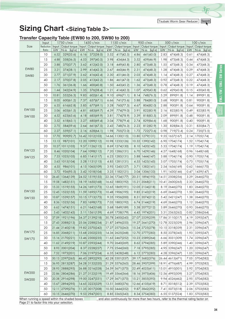
SizeInput 1750 r/min 1450 r/min 1150 r/min 950 r/min 500 r/min 100 r/min
ReductionRatio
Input Output torque Input Output torque Input Output torque Input Output torque Input Output torque Input Output torquekW N·m (kgf·m) kW N·m (kgf·m) kW N·m (kgf·m) kW N·m (kgf·m) kW N·m (kgf·m) kW N·m (kgf·m)
EW80
SW80
10 6.52 329(33.6) 6.16 372(38.0) 5.52 417(42.5) 4.86 441(45.0) 2.83 474(48.3) 0.61 474(48.3)
15 4.88 358(36.5) 4.53 397(40.5) 3.98 434(44.3) 3.52 459(46.9) 1.98 473(48.3) 0.44 474(48.3)
20 3.88 370(37.7) 3.62 412(42.0) 3.18 449(45.8) 2.80 473(48.3) 1.55 473(48.3) 0.34 473(48.3)
25 3.21 374(38.1) 2.99 414(42.3) 2.67 460(46.9) 2.31 474(48.3) 1.28 474(48.3) 0.29 474(48.3)
30 2.77 371(37.9) 2.62 416(42.4) 2.30 451(46.0) 2.03 474(48.3) 1.14 474(48.3) 0.27 474(48.3)
40 2.17 370(37.8) 2.05 413(42.2) 1.86 461(47.0) 1.62 473(48.3) 0.92 473(48.3) 0.22 474(48.3)
50 1.76 361(36.8) 1.66 400(40.8) 1.50 443(45.2) 1.36 473(48.3) 0.78 474(48.3) 0.19 474(48.3)
60 1.44 342(34.9) 1.35 376(38.4) 1.21 414(42.3) 1.07 429(43.8) 0.62 429(43.8) 0.15 430(43.8)
EW100
SW100
10 10.81 552(56.3) 9.83 602(61.4) 9.10 696(71.1) 8.14 748(76.3) 5.29 899(91.8) 1.14 899(91.8)
15 8.05 600(61.2) 7.37 657(67.1) 6.66 741(75.6) 5.88 784(80.0) 3.68 900(91.8) 0.81 900(91.8)
20 6.35 616(62.8) 5.85 677(69.1) 5.28 760(77.5) 4.67 804(82.0) 2.88 900(91.8) 0.64 900(91.8)
25 5.06 603(61.5) 4.81 683(69.7) 4.39 774(79.0) 3.91 822(83.9) 2.16 822(83.9) 0.49 822(83.9)
30 4.52 623(63.6) 4.18 685(69.9) 3.81 774(78.9) 3.39 818(83.5) 2.09 899(91.8) 0.48 900(91.8)
40 3.52 618(63.1) 3.27 680(69.4) 3.04 778(79.4) 2.74 829(84.6) 1.68 900(91.8) 0.40 900(91.8)
50 2.75 584(59.6) 2.64 661(67.5) 2.43 748(76.3) 2.23 812(82.9) 1.30 828(84.5) 0.31 830(84.7)
60 2.27 559(57.1) 2.16 628(64.1) 1.98 705(72.0) 1.72 722(73.6) 0.98 719(73.4) 0.24 720(73.5)
EW125
SW125
10 17.70 909(92.7) 16.42 1012(103) 14.66 1130(115) 13.80 1279(131) 9.55 1637(167) 2.14 1705(174)
15 13.13 987(101) 12.20 1099(112) 10.98 1233(126) 10.32 1390(142) 6.90 1704(174) 1.52 1704(174)
20 10.27 1011(103) 9.57 1126(115) 8.69 1274(130) 8.10 1420(145) 5.33 1704(174) 1.19 1704(174)
25 8.46 1020(104) 7.64 1098(112) 7.20 1286(131) 6.70 1429(146) 4.27 1648(168) 0.96 1648(168)
30 7.33 1025(105) 6.85 1141(117) 6.23 1285(131) 5.88 1444(147) 3.88 1704(174) 0.90 1705(174)
40 5.63 1015(104) 5.28 1131(115) 4.85 1281(131) 4.55 1425(145) 3.07 1705(174) 0.73 1705(174)
50 4.55 986(101) 4.15 1065(109) 3.95 1245(127) 3.71 1382(141) 2.54 1656(169) 0.62 1666(170)
60 3.72 936(95.5) 3.42 1018(104) 3.25 1182(121) 3.04 1306(133) 1.91 1430(146) 0.47 1439(147)
EW150
SW150
10 26.45 1364(139) 24.52 1519(155) 22.36 1734(177) 20.31 1894(193) 14.51 2508(256) 3.29 2646(270)
15 19.58 1482(151) 18.19 1650(168) 16.62 1883(192) 15.21 2068(211) 10.41 2600(265) 2.33 2646(270)
20 15.33 1519(155) 14.26 1691(173) 12.65 1869(191) 12.05 2134(218) 8.19 2646(270) 1.83 2646(270)
25 12.45 1522(155) 11.59 1695(173) 10.48 1906(195) 9.85 2143(219) 6.69 2646(270) 1.50 2646(270)
30 10.87 1539(157) 10.15 1713(175) 9.35 1956(200) 8.31 2074(212) 5.42 2421(247) 1.38 2646(270)
40 8.36 1525(156) 7.83 1698(173) 7.03 1883(192) 6.74 2144(219) 4.69 2646(270) 1.12 2646(270)
50 6.62 1474(151) 6.21 1642(168) 5.68 1849(189) 5.38 2077(212) 3.89 2646(270) 0.93 2646(270)
60 5.43 1402(143) 5.11 1561(159) 4.69 1758(179) 4.45 1974(201) 3.31 2563(262) 0.82 2586(264)
EW175
SW175
10 37.09 1921(196) 34.37 2139(218) 30.78 2400(245) 27.07 2539(259) 17.86 3110(317) 4.19 3395(347)
15 27.43 2088(213) 25.06 2288(234) 21.87 2496(255) 19.27 2641(270) 12.78 3223(329) 2.96 3396(347)
20 21.44 2140(218) 19.82 2370(242) 17.27 2575(263) 15.24 2725(278) 10.15 3318(339) 2.31 3396(347)
25 16.85 2068(211) 15.68 2302(235) 14.36 2625(268) 12.70 2777(283) 8.50 3378(345) 1.93 3395(347)
30 15.16 2170(221) 13.46 2300(235) 11.63 2467(252) 10.23 2589(264) 6.66 3031(309) 1.74 3396(347)
40 11.62 2149(219) 10.87 2393(244) 9.70 2640(269) 8.62 2794(285) 5.89 3390(346) 1.40 3396(347)
50 8.93 2001(204) 8.37 2228(227) 7.75 2544(260) 7.18 2795(285) 4.95 3396(347) 1.20 3396(347)
60 7.52 1973(201) 7.06 2197(224) 6.35 2428(248) 6.12 2773(283) 4.28 3396(347) 1.05 3396(347)
EW200
SW200
10 50.13 2597(265) 46.43 2892(295) 42.28 3301(337) 39.17 3682(376) 26.44 4613(471) 7.05 5704(582)
15 36.95 2813(287) 34.28 3132(320) 31.29 3576(365) 28.46 3907(399) 18.91 4776(487) 4.99 5703(582)
20 28.93 2888(295) 26.88 3216(328) 24.59 3671(375) 22.49 4025(411) 15.01 4910(501) 3.92 5704(582)
25 22.86 2804(286) 21.27 3122(319) 19.49 3564(364) 18.16 3975(406) 12.56 4992(509) 3.27 5704(582)
30 20.38 2916(298) 19.00 3247(331) 17.29 3671(375) 15.21 3855(393) 9.94 4526(462) 2.95 5704(582)
40 15.67 2894(295) 14.65 3223(329) 13.51 3680(376) 12.66 4105(419) 8.71 5018(512) 2.39 5703(582)
50 12.11 2709(276) 11.35 3017(308) 10.50 3444(352) 9.87 3842(392) 7.41 5073(518) 2.06 5703(582)
60 10.15 2646(270) 9.53 2947(301) 8.85 3365(343) 8.34 3754(383) 6.55 5137(524) 1.83 5703(582)
When running a speed within the shaded boxes , and also continuously for more than two hours, refer to the thermal rating factor on Page 21 to factor this into your selection.
Sizing Chart <Sizing Table 3>
Transfer Capacity Table (EW80 to 200, SW80 to 200)
35
一段減速 (減速比1/10~1/60)Single Reduction Reducer (Reduction ratio 1/10 to 1/60)
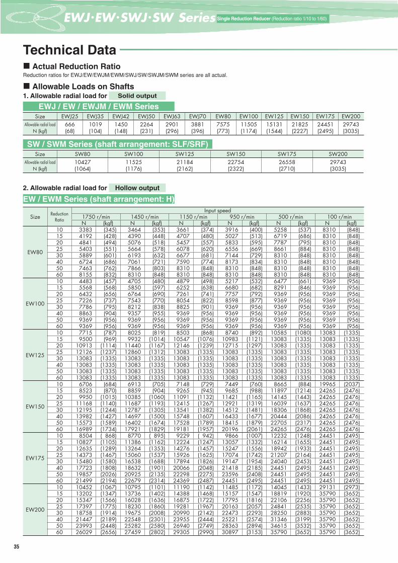
Technical Data Actual Reduction Ratio
Reduction ratios for EWJ/EW/EWJM/EWM/SWJ/SW/SWJM/SWM series are all actual.
Allowable Loads on Shafts1. Allowable radial load for Solid output
Size EWJ25 EWJ35 EWJ42 EWJ50 EWJ63 EWJ70 EW80 EW100 EW125 EW150 EW175 EW200Allowable radial load
N (kgf)666(68)
1019(104)
1450(148)
2264(231)
2901(296)
3881(396)
7575(773)
11505(1174)
15131(1544)
21825(2227)
24451(2495)
29743(3035)
Size SW80 SW100 SW125 SW150 SW175 SW200Allowable radial load
N (kgf)10427(1064)
11525(1176)
21184(2162)
22754(2322)
26558(2710)
29743(3035)
2. Allowable radial load for Hollow output
Size ReductionRatio
Input speed1750 r/min 1450 r/min 1150 r/min 950 r/min 500 r/min 100 r/minN (kgf) N (kgf) N (kgf) N (kgf) N (kgf) N (kgf)
EW80
10 3383 (345) 3464 (353) 3661 (374) 3916 (400) 5258 (537) 8310 (848)15 4192 (428) 4390 (448) 4707 (480) 5027 (513) 6719 (686) 8310 (848)20 4841 (494) 5076 (518) 5457 (557) 5833 (595) 7787 (795) 8310 (848)25 5403 (551) 5664 (578) 6078 (620) 6556 (669) 8661 (884) 8310 (848)30 5889 (601) 6193 (632) 6677 (681) 7144 (729) 8310 (848) 8310 (848)40 6724 (686) 7061 (721) 7590 (774) 8173 (834) 8310 (848) 8310 (848)50 7463 (762) 7866 (803) 8310 (848) 8310 (848) 8310 (848) 8310 (848)60 8155 (832) 8310 (848) 8310 (848) 8310 (848) 8310 (848) 8310 (848)
EW100
10 4483 (457) 4705 (480) 4879 (498) 5217 (532) 6477 (661) 9369 (956)15 5568 (568) 5850 (597) 6252 (638) 6680 (682) 8291 (846) 9369 (956)20 6432 (656) 6764 (690) 7261 (741) 7757 (792) 9369 (956) 9369 (956)25 7226 (737) 7543 (770) 8054 (822) 8598 (877) 9369 (956) 9369 (956)30 7786 (795) 8212 (838) 8825 (901) 9369 (956) 9369 (956) 9369 (956)40 8863 (904) 9357 (955) 9369 (956) 9369 (956) 9369 (956) 9369 (956)50 9369 (956) 9369 (956) 9369 (956) 9369 (956) 9369 (956) 9369 (956)60 9369 (956) 9369 (956) 9369 (956) 9369 (956) 9369 (956) 9369 (956)
EW125
10 7715 (787) 8025 (819) 8503 (868) 8740 (892) 10585 (1080) 13083 (1335)15 9500 (969) 9932 (1014) 10547 (1076) 10983 (1121) 13083 (1335) 13083 (1335)20 10913 (1114) 11440 (1167) 12146 (1239) 12715 (1297) 13083 (1335) 13083 (1335)25 12126 (1237) 12860 (1312) 13083 (1335) 13083 (1335) 13083 (1335) 13083 (1335)30 13083 (1335) 13083 (1335) 13083 (1335) 13083 (1335) 13083 (1335) 13083 (1335)40 13083 (1335) 13083 (1335) 13083 (1335) 13083 (1335) 13083 (1335) 13083 (1335)50 13083 (1335) 13083 (1335) 13083 (1335) 13083 (1335) 13083 (1335) 13083 (1335)60 13083 (1335) 13083 (1335) 13083 (1335) 13083 (1335) 13083 (1335) 13083 (1335)
EW150
10 6706 (684) 6913 (705) 7148 (729) 7449 (760) 8665 (884) 19965 (2037)15 8523 (870) 8859 (904) 9265 (945) 9685 (988) 11897 (1214) 24265 (2476)20 9950 (1015) 10385 (1060) 11091 (1132) 11421 (1165) 14145 (1443) 24265 (2476)25 11168 (1140) 11687 (1193) 12415 (1267) 12921 (1319) 16039 (1637) 24265 (2476)30 12195 (1244) 12787 (1305) 13541 (1382) 14512 (1481) 18306 (1868) 24265 (2476)40 13982 (1427) 14697 (1500) 15748 (1607) 16433 (1677) 20444 (2086) 24265 (2476)50 15573 (1589) 16402 (1674) 17528 (1789) 18415 (1879) 22705 (2317) 24265 (2476)60 16989 (1734) 17921 (1829) 19181 (1957) 20196 (2061) 24265 (2476) 24265 (2476)
EW175
10 8504 ( 868) 8770 ( 895) 9229 ( 942) 9866 (1007) 12232 (1248) 24451 (2495)15 10827 (1105) 11386 (1162) 12224 (1247) 13057 (1332) 16214 (1655) 24451 (2495)20 12635 (1289) 13264 (1353) 14276 (1457) 15247 (1556) 18942 (1933) 24451 (2495)25 14373 (1467) 15060 (1537) 15926 (1625) 17074 (1742) 21207 (2164) 24451 (2495)30 15480 (1580) 16538 (1688) 17894 (1826) 19147 (1954) 24040 (2453) 24451 (2495)40 17723 (1808) 18632 (1901) 20066 (2048) 21418 (2185) 24451 (2495) 24451 (2495)50 19857 (2026) 20925 (2135) 22298 (2275) 23596 (2408) 24451 (2495) 24451 (2495)60 21499 (2194) 22679 (2314) 24369 (2487) 24451 (2495) 24451 (2495) 24451 (2495)
EW200
10 10452 (1067) 10795 (1101) 11190 (1142) 11485 (1172) 14045 (1433) 29131 (2973)15 13202 (1347) 13736 (1402) 14388 (1468) 15157 (1547) 18819 (1920) 35790 (3652)20 15347 (1566) 16028 (1636) 16875 (1722) 17795 (1816) 22106 (2256) 35790 (3652)25 17397 (1775) 18230 (1860) 19281 (1967) 20163 (2057) 24841 (2535) 35790 (3652)30 18758 (1914) 19675 (2008) 20990 (2142) 22473 (2293) 28250 (2883) 35790 (3652)40 21447 (2189) 22548 (2301) 23955 (2444) 25221 (2574) 31346 (3199) 35790 (3652)50 23993 (2448) 25282 (2580) 26940 (2749) 28363 (2894) 34615 (3532) 35790 (3652)60 26029 (2656) 27459 (2802) 29305 (2990) 30897 (3153) 35790 (3652) 35790 (3652)
EWJ / EW / EWJM / EWM Series
EW / EWM Series (shaft arrangement: H)
SW / SWM Series (shaft arrangement: SLF/SRF)
36
EWJ
/ EW
/ SW
J / S
W S
erie
sSi
ngle
Red
uctio
n Ge
ar R
educ
ers
Spec
ifi ca
tions
3Eつばきウォーム減速機Tsubaki Worm Gear Reducer Search
Sing
le R
educ
tion
Gear
Red
ucer
sSi
ze42
Sing
le R
educ
tion
Gear
Red
ucer
sSi
ze50
Sing
le R
educ
tion
Gear
Red
ucer
sSi
ze63
Sing
le R
educ
tion
Gear
Red
ucer
sSi
ze70
Sing
le R
educ
tion
Gear
Red
ucer
sSi
ze80
Sing
le R
educ
tion
Gear
Red
ucer
sSi
ze10
0
Sing
le R
educ
tion
Gear
Red
ucer
sSi
ze12
5
Sing
le R
educ
tion
Gear
Red
ucer
sSi
ze15
0
Sing
le R
educ
tion
Gear
Red
ucer
sSi
ze17
5
Sing
le R
educ
tion
Gear
Red
ucer
sSi
ze20
0
Single
Red
uctio
n Ge
ar Re
duce
rsSiz
e25/3
5
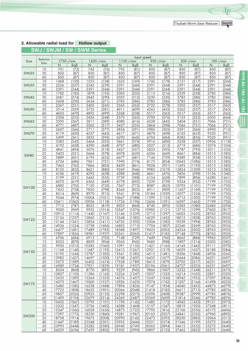
2. Allowable radial load for Hollow output
Size ReductionRatio
Input speed1750 r/min 1450 r/min 1150 r/min 950 r/min 500 r/min 100 r/minN (kgf) N (kgf) N (kgf) N (kgf) N (kgf) N (kgf)
SWJ2510 701 (72) 743 (76) 793 (81) 850 (87) 850 (87) 850 (87)30 850 (87) 850 (87) 850 (87) 850 (87) 850 (87) 850 (87)60 850 (87) 850 (87) 850 (87) 850 (87) 850 (87) 850 (87)
SWJ3510 1468 (150) 1553 (158) 1653 (169) 1742 (178) 2131 (217) 2391 (244)30 2226 (227) 2342 (239) 2391 (244) 2391 (244) 2391 (244) 2391 (244)60 2391 (244) 2391 (244) 2391 (244) 2391 (244) 2391 (244) 2391 (244)
SWJ4210 1782 (182) 1878 (192) 2005 (205) 2113 (216) 2529 (258) 3783 (386)30 2681 (274) 2845 (290) 3055 (312) 3230 (330) 3783 (386) 3783 (386)60 3428 (350) 3634 (371) 3783 (386) 3783 (386) 3783 (386) 3783 (386)
SWJ5010 2267 (231) 2405 (245) 2565 (262) 2722 (278) 3305 (337) 5517 (563)30 3514 (359) 3733 (381) 4011 (409) 4263 (435) 5262 (537) 5517 (563)60 4603 (470) 4892 (499) 5268 (538) 5517 (563) 5517 (563) 5517 (563)
SWJ6310 2304 (235) 2426 (248) 2570 (262) 2700 (276) 3153 (322) 6505 (664)30 3595 (367) 3811 (389) 4080 (416) 4328 (442) 5404 (551) 7066 (721)60 4771 (487) 5062 (517) 5437 (555) 5864 (598) 7066 (721) 7066 (721)
SWJ7010 2607 (266) 2711 (277) 2854 (291) 2985 (305) 3591 (366) 6990 (713)30 4119 (420) 4337 (443) 4617 (471) 4878 (498) 6103 (623) 9320 (951)60 5499 (561) 5832 (595) 6290 (642) 6704 (684) 8385 (856) 9320 (951)
SW80
10 3383 (345) 3464 (353) 3661 (374) 3916 (400) 5258 (537) 10956 (1118)15 4192 (428) 4390 (448) 4707 (480) 5027 (513) 6719 (686) 13274 (1354)20 4841 (494) 5076 (518) 5457 (557) 5833 (595) 7787 (795) 15011 (1532)25 5403 (551) 5664 (578) 6078 (620) 6556 (669) 8661 (884) 15513 (1583)30 5889 (601) 6193 (632) 6677 (681) 7144 (729) 9389 (958) 15513 (1583)40 6724 (686) 7061 (721) 7590 (774) 8173 (834) 10643 (1086) 15513 (1583)50 7463 (762) 7866 (803) 8439 (861) 9028 (921) 11693 (1193) 15513 (1583)60 8155 (832) 8621 (880) 9269 (946) 9983 (1019) 12824 (1309) 15513 (1583)
SW100
10 4106 (419) 4292 (438) 4388 (448) 4661 (476) 5856 (598) 13136 (1340)15 5199 (531) 5443 (555) 5759 (588) 6154 (628) 7899 (806) 16280 (1661)20 6070 (619) 6365 (649) 6778 (692) 7239 (739) 9334 (952) 17199 (1755)25 6882 (702) 7150 (730) 7567 (772) 8087 (825) 10793 (1101) 17199 (1755)30 7432 (758) 7820 (798) 8345 (852) 8911 (909) 11457 (1169) 17199 (1755)40 8514 (869) 8970 (915) 9541 (974) 10184 (1039) 13077 (1334) 17199 (1755)50 9544 (974) 10004 (1021) 10667 (1088) 11299 (1153) 14715 (1502) 17199 (1755)60 10411 (1062) 10956 (1118) 11724 (1196) 12656 (1291) 16297 (1663) 17199 (1755)
SW125
10 7715 (787) 8025 (819) 8503 (868) 8740 (892) 10585 (1080) 22485 (2294)15 9500 (969) 9932 (1014) 10547 (1076) 10983 (1121) 13710 (1399) 27605 (2817)20 10913 (1114) 11440 (1167) 12146 (1239) 12715 (1297) 16022 (1635) 28763 (2935)25 12126 (1237) 12860 (1312) 13548 (1382) 14229 (1452) 18015 (1838) 28763 (2935)30 13144 (1341) 13824 (1411) 14752 (1505) 15504 (1582) 19539 (1994) 28763 (2935)40 14936 (1524) 15738 (1606) 16802 (1715) 17704 (1807) 22240 (2269) 28763 (2935)50 16477 (1681) 17489 (1785) 18588 (1897) 19625 (2003) 24524 (2502) 28763 (2935)60 17897 (1826) 18981 (1937) 20241 (2065) 21417 (2185) 27148 (2770) 28763 (2935)
SW150
10 6706 (684) 6913 (705) 7148 (729) 7449 (760) 8665 (884) 19965 (2037)15 8523 (870) 8859 (904) 9265 (945) 9685 (988) 11897 (1214) 25303 (2582)20 9950 (1015) 10385 (1060) 11091 (1132) 11421 (1165) 14145 (1443) 29111 (2970)25 11168 (1140) 11687 (1193) 12415 (1267) 12921 (1319) 16039 (1637) 32180 (3284)30 12195 (1244) 12787 (1305) 13541 (1382) 14512 (1481) 18306 (1868) 34936 (3565)40 13982 (1427) 14697 (1500) 15748 (1607) 16433 (1677) 20444 (2086) 36231 (3697)50 15573 (1589) 16402 (1674) 17528 (1789) 18415 (1879) 22705 (2317) 36231 (3697)60 16989 (1734) 17921 (1829) 19181 (1957) 20196 (2061) 24727 (2523) 36231 (3697)
SW175
10 8504 (868) 8770 (895) 9229 (942) 9866 (1007) 12232 (1248) 26211 (2675)15 10827 (1105) 11386 (1162) 12224 (1247) 13057 (1332) 16214 (1655) 32851 (3352)20 12635 (1289) 13264 (1353) 14276 (1457) 15247 (1556) 18942 (1933) 37597 (3836)25 14373 (1467) 15060 (1537) 15926 (1625) 17074 (1742) 21207 (2164) 41498 (4235)30 15480 (1580) 16538 (1688) 17894 (1826) 19147 (1954) 24040 (2453) 44873 (4579)40 17723 (1808) 18632 (1901) 20066 (2048) 21418 (2185) 26611 (2715) 47785 (4876)50 19857 (2026) 20925 (2135) 22298 (2275) 23596 (2408) 29387 (2999) 47785 (4876)60 21499 (2194) 22679 (2314) 24369 (2487) 25569 (2609) 31814 (3246) 47785 (4876)
SW200
10 10452 (1067) 10795 (1101) 11190 (1142) 11485 (1172) 14045 (1433) 29131 (2973)15 13202 (1347) 13736 (1402) 14388 (1468) 15157 (1547) 18819 (1920) 37348 (3811)20 15347 (1566) 16028 (1636) 16875 (1722) 17795 (1816) 22106 (2256) 43175 (4406)25 17397 (1775) 18230 (1860) 19281 (1967) 20163 (2057) 24841 (2535) 47945 (4892)30 18758 (1914) 19675 (2008) 20990 (2142) 22473 (2293) 28250 (2883) 52064 (5313)40 21447 (2189) 22548 (2301) 23955 (2444) 25221 (2574) 31346 (3199) 55272 (5640)50 23993 (2448) 25282 (2580) 26940 (2749) 28363 (2894) 34615 (3532) 55272 (5640)60 26029 (2656) 27459 (2802) 29305 (2990) 30897 (3153) 37462 (3823) 55272 (5640)
SWJ / SWJM / SW / SWM Series
37
一段減速 (減速比1/10~1/60)Single Reduction Reducer (Reduction ratio 1/10 to 1/60)
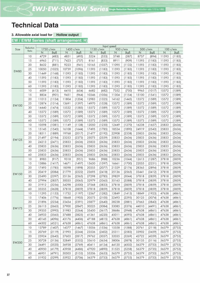
3. Allowable axial load for Hollow output
Size ReductionRatio
Input speed1750 r/min 1450 r/min 1150 r/min 950 r/min 500 r/min 100 r/minN (kgf) N (kgf) N (kgf) N (kgf) N (kgf) N (kgf)
EW80
10 4729 (483) 4851 (495) 5224 (533) 5748 (587) 8757 (894) 11593 (1183)15 6963 (711) 7423 (757) 8161 (833) 8911 (909) 11593 (1183) 11593 (1183)20 8632 (881) 9223 (941) 10165 (1037) 11095 (1132) 11593 (1183) 11593 (1183)25 10050 (1025) 10739 (1096) 11593 (1183) 11593 (1183) 11593 (1183) 11593 (1183)30 11449 (1168) 11593 (1183) 11593 (1183) 11593 (1183) 11593 (1183) 11593 (1183)40 11593 (1183) 11593 (1183) 11593 (1183) 11593 (1183) 11593 (1183) 11593 (1183)50 11593 (1183) 11593 (1183) 11593 (1183) 11593 (1183) 11593 (1183) 11593 (1183)60 11593 (1183) 11593 (1183) 11593 (1183) 11593 (1183) 11593 (1183) 11593 (1183)
EW100
10 6009 (613) 6410 (654) 6682 (682) 7352 (750) 9965 (1017) 15572 (1589)15 8834 (901) 9451 (964) 10346 (1056) 11304 (1154) 15100 (1541) 15572 (1589)20 11013 (1124) 11804 (1204) 12983 (1325) 14162 (1445) 15572 (1589) 15572 (1589)25 12874 (1314) 13691 (1397) 14970 (1528) 15572 (1589) 15572 (1589) 15572 (1589)30 14440 (1474) 15532 (1585) 15572 (1589) 15572 (1589) 15572 (1589) 15572 (1589)40 15572 (1589) 15572 (1589) 15572 (1589) 15572 (1589) 15572 (1589) 15572 (1589)50 15572 (1589) 15572 (1589) 15572 (1589) 15572 (1589) 15572 (1589) 15572 (1589)60 15572 (1589) 15572 (1589) 15572 (1589) 15572 (1589) 15572 (1589) 15572 (1589)
EW125
10 10598 (1081) 11149 (1138) 12050 (1230) 12449 (1270) 16238 (1657) 25833 (2636)15 15145 (1545) 16108 (1644) 17495 (1785) 18524 (1890) 24919 (2543) 25833 (2636)20 18511 (1889) 19768 (2017) 21477 (2192) 22908 (2338) 25833 (2636) 25833 (2636)25 21497 (2194) 23253 (2373) 25075 (2559) 25833 (2636) 25833 (2636) 25833 (2636)30 24213 (2471) 25833 (2636) 25833 (2636) 25833 (2636) 25833 (2636) 25833 (2636)40 25833 (2636) 25833 (2636) 25833 (2636) 25833 (2636) 25833 (2636) 25833 (2636)50 25833 (2636) 25833 (2636) 25833 (2636) 25833 (2636) 25833 (2636) 25833 (2636)60 25833 (2636) 25833 (2636) 25833 (2636) 25833 (2636) 25833 (2636) 25833 (2636)
EW150
10 8983 (917) 9318 (951) 9686 (988) 10236 (1044) 12613 (1287) 37818 (3859)15 13886 (1417) 14671 (1497) 15650 (1597) 16661 (1700) 22055 (2251) 37818 (3859)20 17493 (1785) 18598 (1898) 20355 (2077) 21329 (2176) 28365 (2894) 37818 (3859)25 20419 (2084) 21779 (2222) 23695 (2418) 25136 (2565) 33441 (3412) 37818 (3859)30 23490 (2397) 25136 (2565) 27298 (2785) 29829 (3044) 37818 (2859) 37818 (3859)40 27994 (2857) 30035 (3065) 32979 (3365) 35163 (3588) 37818 (3859) 37818 (3859)50 31912 (3256) 34298 (3500) 37568 (3833) 37818 (3859) 37818 (3859) 37818 (3859)60 35555 (3628) 37818 (3859) 37818 (3859) 37818 (3859) 37818 (3859) 37818 (3859)
EW175
10 11295 (1153) 11732 (1197) 12567 (1282) 13849 (1413) 18849 (1923) 47638 (4861)15 17406 (1776) 18668 (1905) 20575 (2100) 22493 (2295) 30125 (3074) 47638 (4861)20 21896 (2234) 23434 (2391) 25877 (2640) 28238 (2881) 37663 (3843) 47638 (4861)25 26113 (2665) 27900 (2847) 30225 (3084) 33085 (3376) 44010 (4491) 47638 (4861)30 29355 (2995) 31983 (3264) 35450 (3617) 38686 (3948) 47638 (4861) 47638 (4861)40 34933 (3565) 37488 (3825) 41361 (4220) 45011 (4593) 47638 (4861) 47638 (4861)50 40145 (4096) 43176 (4406) 47188 (4815) 47638 (4861) 47638 (4861) 47638 (4861)60 44302 (4521) 47638 (4861) 47638 (4861) 47638 (4861) 47638 (4861) 47638 (4861)
EW200
10 13789 (1407) 14377 (1467) 15056 (1536) 15558 (1588) 20761 (2118) 56379 (5753)15 20769 (2119) 21993 (2244) 23536 (2402) 25311 (2583) 33902 (3459) 56379 (5753)20 25924 (2645) 27603 (2817) 29762 (3037) 32035 (3269) 42722 (4359) 56379 (5753)25 30728 (3136) 32849 (3352) 35610 (3634) 38006 (3878) 50135 (5116) 56379 (5753)30 34491 (3520) 36938 (3769) 40411 (4124) 44120 (4502) 56379 (5753) 56379 (5753)40 40950 (4179) 43958 (4486) 47920 (4890) 51525 (5258) 56379 (5735) 56379 (5753)50 46951 (4791) 50503 (5153) 55206 (5633) 56379 (5753) 56379 (5753) 56379 (5753)60 51932 (5299) 55922 (5706) 56379 (5753) 56379 (5753) 56379 (5753) 56379 (5753)
EW / EWM Series (shaft arrangement: H)
Technical Data

38
EWJ
/ EW
/ SW
J / S
W S
erie
sSi
ngle
Red
uctio
n Ge
ar R
educ
ers
Spec
ifi ca
tions
3Eつばきウォーム減速機Tsubaki Worm Gear Reducer Search
Sing
le R
educ
tion
Gear
Red
ucer
sSi
ze42
Sing
le R
educ
tion
Gear
Red
ucer
sSi
ze50
Sing
le R
educ
tion
Gear
Red
ucer
sSi
ze63
Sing
le R
educ
tion
Gear
Red
ucer
sSi
ze70
Sing
le R
educ
tion
Gear
Red
ucer
sSi
ze80
Sing
le R
educ
tion
Gear
Red
ucer
sSi
ze10
0
Sing
le R
educ
tion
Gear
Red
ucer
sSi
ze12
5
Sing
le R
educ
tion
Gear
Red
ucer
sSi
ze15
0
Sing
le R
educ
tion
Gear
Red
ucer
sSi
ze17
5
Sing
le R
educ
tion
Gear
Red
ucer
sSi
ze20
0
Single
Red
uctio
n Ge
ar Re
duce
rsSiz
e25/3
5
3. Allowable axial load for Hollow output
Size ReductionRatio
Input speed1750 r/min 1450 r/min 1150 r/min 950 r/min 500 r/min 100 r/minN (kgf) N (kgf) N (kgf) N (kgf) N (kgf) N (kgf)
SWJ2510 1093 (112) 1180 (120) 1287 (131) 1443 (147) 1838 (188) 1838 (188)30 1838 (188) 1838 (188) 1838 (188) 1838 (188) 1838 (188) 1838 (188)60 1838 (188) 1838 (188) 1838 (188) 1838 (188) 1838 (188) 1838 (188)
SWJ3510 2787 (284) 3005 (307) 3263 (333) 3501 (357) 4141 (423) 4141 (423)30 4141 (423) 4141 (423) 4141 (423) 4141 (423) 4141 (423) 4141 (423)60 4141 (423) 4141 (423) 4141 (423) 4141 (423) 4141 (423) 4141 (423)
SWJ4210 3449 (352) 3698 (377) 4034 (412) 4329 (442) 5505 (562) 5733 (585)30 5733 (585) 5733 (585) 5733 (585) 5733 (585) 5733 (585) 5733 (585)60 5733 (585) 5733 (585) 5733 (585) 5733 (585) 5733 (585) 5733 (585)
SWJ5010 3643 (372) 3940 (402) 4291 (438) 4645 (474) 6016 (614) 7546 (770)30 6845 (698) 7410 (756) 7546 (770) 7546 (770) 7546 (770) 7546 (770)60 7546 (770) 7546 (770) 7546 (770) 7546 (770) 7546 (770) 7546 (770)
SWJ6310 4148 (423) 4443 (453) 4798 (490) 5126 (523) 6252 (638) 8281 (845)30 7512 (767) 8099 (826) 8281 (845) 8281 (845) 8281 (845) 8281 (845)60 8281 (845) 8281 (845) 8281 (845) 8281 (845) 8281 (845) 8281 (845)
SWJ7010 4846 (494) 5107 (521) 5474 (559) 5818 (594) 7475 (763) 11613 (1185)30 9409 (960) 10107 (1031) 11031 (1126) 11613 (1185) 11613 (1185) 11613 (1185)60 11613 (1185) 11613 (1185) 11613 (1185) 11613 (1185) 11613 (1185) 11613 (1185)
SW80
10 4729 (483) 4851 (495) 5224 (533) 5748 (587) 8757 (894) 13217 (1349)15 6963 (711) 7423 (757) 8161 (833) 8911 (909) 12984 (1325) 14190 (1448)20 8632 (881) 9223 (941) 10165 (1037) 11095 (1132) 14793 (1509) 14582 (1488)25 10050 (1025) 10739 (1096) 11806 (1205) 13000 (1327) 15011 (1532) 14808 (1511)30 11449 (1168) 12284 (1254) 13563 (1384) 14794 (1510) 15356 (1567) 15146 (1546)40 13579 (1386) 14553 (1485) 15673 (1599) 15626 (1595) 15544 (1586) 15339 (1565)50 15451 (1577) 15899 (1622) 15793 (1612) 15731 (1605) 15651 (1597) 15453 (1577)60 16067 (1640) 15993 (1632) 15903 (1623) 15876 (1620) 15807 (1613) 15625 (1594)
SW100
10 5189 (529) 5502 (561) 5594 (571) 6102 (623) 8515 (869) 20964 (2139)15 8101 (827) 8635 (881) 9339 (953) 10217 (1043) 14258 (1455) 21560 (2200)20 10331 (1054) 11039 (1126) 12042 (1229) 13138 (1341) 18234 (1861) 21560 (2200)25 12232 (1248) 12949 (1321) 14033 (1432) 15309 (1562) 21560 (2200) 21560 (2200)30 13815 (1410) 14830 (1513) 16219 (1655) 17663 (1802) 21560 (2200) 21560 (2200)40 16521 (1686) 17760 (1812) 19371 (1977) 21077 (2151) 21560 (2200) 21560 (2200)50 18962 (1935) 20295 (2071) 21560 (2200) 21560 (2200) 21560 (2200) 21560 (2200)60 21074 (2150) 21560 (2200) 21560 (2200) 21560 (2200) 21560 (2200) 21560 (2200)
SW125
10 10598 (1081) 11149 (1138) 12050 (1230) 12449 (1270) 16238 (1657) 30488 (3111)15 15145 (1545) 16108 (1644) 17495 (1785) 18524 (1890) 24919 (2543) 32787 (3346)20 18511 (1889) 19768 (2017) 21477 (2192) 22908 (2338) 31008 (3164) 33615 (3430)25 21497 (2194) 23253 (2373) 25075 (2559) 26857 (2741) 34822 (3553) 34348 (3505)30 24213 (2471) 25979 (2651) 28410 (2899) 30473 (3109) 35522 (3625) 35053 (3577)40 28527 (2911) 30668 (3129) 33558 (3424) 36087 (3682) 35921 (3665) 35464 (3619)50 32330 (3299) 34989 (3570) 36505 (3725) 36505 (3725) 36278 (3702) 35829 (3656)60 35787 (3652) 36505 (3725) 36505 (3725) 36505 (3725) 36505 (3725) 36343 (3708)
SW150
10 8983 (917) 9318 (951) 9686 (988) 10236 (1044) 12613 (1287) 16089 (1642)15 13886 (1417) 14671 (1497) 15650 (1597) 16661 (1700) 19897 (2030) 19105 (1949)20 17493 (1785) 18598 (1898) 20355 (2077) 21329 (2176) 20914 (2134) 20283 (2070)25 20419 (2084) 21779 (2222) 22945 (2341) 22465 (2292) 21372 (2181) 20762 (2119)30 23490 (2397) 24185 (2468) 23828 (2431) 23663 (2415) 23011 (2348) 22077 (2253)40 24782 (2529) 24569 (2507) 24324 (2482) 23989 (2448) 23261 (2374) 22657 (2312)50 24960 (2547) 24767 (2527) 24515 (2501) 24236 (2473) 23479 (2396) 22893 (2336)60 25216 (2573) 25053 (2556) 24840 (2535) 24604 (2511) 23869 (2436) 23306 (2378)
SW175
10 11295 (1153) 11732 (1197) 12567 (1282) 13849 (1413) 18849 (1923) 26945 (2749)15 17406 (1776) 18668 (1905) 20575 (2100) 22493 (2295) 30125 (3074) 30319 (3094)20 21896 (2234) 23434 (2391) 25877 (2640) 28238 (2881) 32465 (3313) 31634 (3228)25 26113 (2665) 27900 (2847) 30225 (3084) 33085 (3376) 33208 (3389) 32508 (3317)30 29355 (2995) 31983 (3264) 35450 (3617) 35456 (3618) 34756 (3546) 33645 (3433)40 34933 (3565) 36177 (3692) 35932 (3666) 35744 (3647) 34957 (3567) 34291 (3499)50 36818 (3757) 36608 (3736) 36306 (3705) 36061 (3680) 35373 (3609) 34723 (3543)60 36967 (3772) 36774 (3752) 36556 (3730) 36245 (3698) 35588 (3631) 34949 (3566)
SW200
10 13789 (1407) 14377 (1467) 15056 (1536) 15558 (1588) 20761 (2118) 22785 (2325)15 20769 (2119) 21993 (2244) 23536 (2402) 25311 (2583) 30020 (3063) 27350 (2791)20 25924 (2645) 27603 (2817) 29762 (3037) 32035 (3269) 31325 (3196) 29171 (2977)25 30728 (3136) 32849 (3352) 34204 (3490) 33663 (3435) 32237 (3289) 30367 (3099)30 34491 (3520) 35464 (3619) 35066 (3578) 34852 (3556) 33993 (3469) 31861 (3251)40 36262 (3700) 35987 (3672) 35591 (3632) 35238 (3596) 34291 (3499) 32756 (3342)50 36677 (3743) 36451 (3719) 36123 (3686) 35807 (3654) 34763 (3547) 33347 (3403)60 36913 (3767) 36714 (3746) 36425 (3717) 36144 (3688) 35098 (3581) 33781 (3447)
SWJ / SWJM / SW / SWM Series
39
一段減速 (減速比1/10~1/60)Single Reduction Reducer (Reduction ratio 1/10 to 1/60)
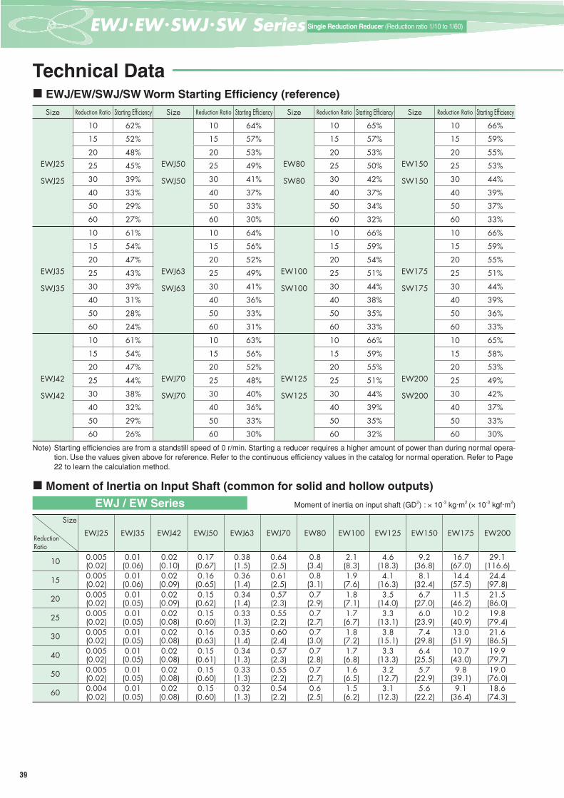
EWJ/EW/SWJ/SW Worm Starting Effi ciency (reference)Size Reduction Ratio Starting Effi ciency Size Reduction Ratio Starting Effi ciency Size Reduction Ratio Starting Effi ciency Size Reduction Ratio Starting Effi ciency
EWJ25
SWJ25
10 62%
EWJ50
SWJ50
10 64%
EW80
SW80
10 65%
EW150
SW150
10 66%
15 52% 15 57% 15 57% 15 59%
20 48% 20 53% 20 53% 20 55%
25 45% 25 49% 25 50% 25 53%
30 39% 30 41% 30 42% 30 44%
40 33% 40 37% 40 37% 40 39%
50 29% 50 33% 50 34% 50 37%
60 27% 60 30% 60 32% 60 33%
EWJ35
SWJ35
10 61%
EWJ63
SWJ63
10 64%
EW100
SW100
10 66%
EW175
SW175
10 66%
15 54% 15 56% 15 59% 15 59%
20 47% 20 52% 20 54% 20 55%
25 43% 25 49% 25 51% 25 51%
30 39% 30 41% 30 44% 30 44%
40 31% 40 36% 40 38% 40 39%
50 28% 50 33% 50 35% 50 36%
60 24% 60 31% 60 33% 60 33%
EWJ42
SWJ42
10 61%
EWJ70
SWJ70
10 63%
EW125
SW125
10 66%
EW200
SW200
10 65%
15 54% 15 56% 15 59% 15 58%
20 47% 20 52% 20 55% 20 53%
25 44% 25 48% 25 51% 25 49%
30 38% 30 40% 30 44% 30 42%
40 32% 40 36% 40 39% 40 37%
50 29% 50 33% 50 35% 50 33%
60 26% 60 30% 60 32% 60 30%
Note) Starting effi ciencies are from a standstill speed of 0 r/min. Starting a reducer requires a higher amount of power than during normal opera-tion. Use the values given above for reference. Refer to the continuous effi ciency values in the catalog for normal operation. Refer to Page 22 to learn the calculation method.
Moment of Inertia on Input Shaft (common for solid and hollow outputs)
Moment of inertia on input shaft (GD2) : × 10-3 kg·m2 (× 10-3 kgf·m2)
Size
ReductionRatio
EWJ25 EWJ35 EWJ42 EWJ50 EWJ63 EWJ70 EW80 EW100 EW125 EW150 EW175 EW200
10 0.005(0.02)
0.01(0.06)
0.02(0.10)
0.17(0.67)
0.38(1.5)
0.64(2.5)
0.8(3.4)
2.1(8.3)
4.6(18.3)
9.2(36.8)
16.7(67.0)
29.1(116.6)
15 0.005(0.02)
0.01(0.06)
0.02(0.09)
0.16(0.65)
0.36(1.4)
0.61(2.5)
0.8(3.1)
1.9(7.6)
4.1(16.3)
8.1(32.4)
14.4(57.5)
24.4(97.8)
20 0.005(0.02)
0.01(0.05)
0.02(0.09)
0.15(0.62)
0.34(1.4)
0.57(2.3)
0.7(2.9)
1.8(7.1)
3.5(14.0)
6.7(27.0)
11.5(46.2)
21.5(86.0)
25 0.005(0.02)
0.01(0.05)
0.02(0.08)
0.15(0.60)
0.33(1.3)
0.55(2.2)
0.7(2.7)
1.7(6.7)
3.3(13.1)
6.0(23.9)
10.2(40.9)
19.8(79.4)
30 0.005(0.02)
0.01(0.05)
0.02(0.08)
0.16(0.63)
0.35(1.4)
0.60(2.4)
0.7(3.0)
1.8(7.2)
3.8(15.1)
7.4(29.8)
13.0(51.9)
21.6(86.5)
40 0.005(0.02)
0.01(0.05)
0.02(0.08)
0.15(0.61)
0.34(1.3)
0.57(2.3)
0.7(2.8)
1.7(6.8)
3.3(13.3)
6.4(25.5)
10.7(43.0)
19.9(79.7)
50 0.005(0.02)
0.01(0.05)
0.02(0.08)
0.15(0.60)
0.33(1.3)
0.55(2.2)
0.7(2.7)
1.6(6.5)
3.2(12.7)
5.7(22.9)
9.8(39.1)
19.0(76.0)
60 0.004(0.02)
0.01(0.05)
0.02(0.08)
0.15(0.60)
0.32(1.3)
0.54(2.2)
0.6(2.5)
1.5(6.2)
3.1(12.3)
5.6(22.2)
9.1(36.4)
18.6(74.3)
EWJ / EW Series
Technical Data

40
EWJ
/ EW
/ SW
J / S
W S
erie
sSi
ngle
Red
uctio
n Ge
ar R
educ
ers
Spec
ifi ca
tions
3Eつばきウォーム減速機Tsubaki Worm Gear Reducer Search
Sing
le R
educ
tion
Gear
Red
ucer
sSi
ze42
Sing
le R
educ
tion
Gear
Red
ucer
sSi
ze50
Sing
le R
educ
tion
Gear
Red
ucer
sSi
ze63
Sing
le R
educ
tion
Gear
Red
ucer
sSi
ze70
Sing
le R
educ
tion
Gear
Red
ucer
sSi
ze80
Sing
le R
educ
tion
Gear
Red
ucer
sSi
ze10
0
Sing
le R
educ
tion
Gear
Red
ucer
sSi
ze12
5
Sing
le R
educ
tion
Gear
Red
ucer
sSi
ze15
0
Sing
le R
educ
tion
Gear
Red
ucer
sSi
ze17
5
Sing
le R
educ
tion
Gear
Red
ucer
sSi
ze20
0
Single
Red
uctio
n Ge
ar Re
duce
rsSiz
e25/3
5
Moment of Inertia on Input Shaft (common for solid and hollow outputs)
Moment of inertia on input shaft (GD2) : × 10-3 kg·m2 (× 10-3 kgf·m2)
Size
ReductionRatio
EWJM42 EWJM50 EWJM63 EWJM70 EWM80 EWM100 EWM125 EWM150
MotorkW
Moment of inertia on input shaft
MotorkW
Moment of inertia on input shaft
MotorkW
Moment of inertia on input shaft
MotorkW
Moment of inertia on input shaft
MotorkW
Moment of inertia on input shaft
MotorkW
Moment of inertia on input shaft
MotorkW
Moment of inertia on input shaft
MotorkW
Moment of inertia on input shaft
10 0.75 1.9(7.5) 0.75 2.0
(7.8) 1.5 4.2(17.0) 2.2 4.5
(18.0) 3.7 7.9(31.4) 5.5 19.7
(78.8) – –
15 0.4 1.0(4.2) 0.75 2.0
(7.8) 1.5 4.2(16.9) 2.2 4.5
(17.9) 3.7 7.9(31.4) 5.5 19.7
(78.8) – –
20 0.4 1.0(4.2) 0.75 1.9
(7.8) 1.5 4.2(16.8) 2.2 4.4
(17.7) 3.7 7.9(31.4) 5.5 19.5
(77.8) – –
25 0.4 1.0(4.2) 0.75 1.9
(7.8) 1.5 4.2(16.8) 1.5 4.4
(17.7) 2.2 4.6(18.4) 3.7 8.9
(35.4) 5.5 21.0(83.8) –
30 0.4 1.0(4.2) 0.75 2.0
(7.8) 1.5 4.2(16.9) 1.5 4.5
(17.9) 2.2 4.6(18.4) 3.7 8.9
(35.4) 5.5 21.5(85.8) –
40 0.2 0.5(2.0) 0.4 1.1
(4.5) 0.75 2.1 (8.5) 0.75 2.3
(9.4) 1.5 4.5(18.1) 2.2 5.6
(22.4) 3.7 10.4(41.4) 5.5 24.0
(95.8)
50 0.2 0.5(2.0) 0.4 1.1
(4.5) 0.75 2.1 (8.4) 0.75 2.3
(9.3) 1.5 4.5(18.1) 2.2 5.6
(22.4) 3.7 10.4(41.4) 5.5 23.5
(93.8)
60 0.2 0.5(2.0) 0.4 1.1
(4.5) 0.75 2.1 (8.4) 0.75 2.3
(9.3) 1.5 4.5(18.1) 2.2 5.4
(21.4) 3.7 10.1(40.4) 5.5 23.2
(92.8)* For motors with brakes, add the moment of inertia and GD2 listed in the Brake Characteristics table on Page 218.
Moment of inertia on input shaft (GD2) : × 10-3 kg·m2 (× 10-3 kgf·m2)
Size
ReductionRatio
SWJ25 SWJ35 SWJ42 SWJ50 SWJ63 SWJ70 SW80 SW100 SW125 SW150 SW175 SW200
10 0.005(0.02)
0.02(0.06)
0.03(0.11)
0.09(0.37)
0.38(1.5)
0.33(1.3)
0.8(3.4)
2.1(8.3)
4.6(18.3)
9.2(36.8)
16.7(67.0)
29.1(116.6)
15 0.005(0.02)
0.01(0.06)
0.02(0.09)
0.09(0.35)
0.36(1.4)
0.30(1.2)
0.8(3.1)
1.9(7.6)
4.1(16.3)
8.1(32.4)
14.4(57.5)
24.4(97.8)
20 0.005(0.02)
0.01(0.05)
0.02(0.09)
0.08(0.31)
0.34(1.4)
0.29(1.2)
0.7(2.9)
1.8(7.1)
3.5(14.0)
6.7(27.0)
11.5(46.2)
21.5(86.0)
25 0.005(0.02)
0.01(0.05)
0.02(0.08)
0.08(0.30)
0.33(1.3)
0.26(1.0)
0.7(2.7)
1.7(6.7)
3.3(13.1)
6.0(23.9)
10.2(40.9)
19.8(79.4)
30 0.005(0.02)
0.01(0.05)
0.02(0.08)
0.08(0.33)
0.35(1.4)
0.28(1.1)
0.7(3.0)
1.8(7.2)
3.8(15.1)
7.4(29.8)
13.0(51.9)
21.6(86.5)
40 0.005(0.02)
0.01(0.05)
0.02(0.08)
0.08(0.31)
0.34(1.3)
0.29(1.1)
0.7(2.8)
1.7(6.8)
3.3(13.3)
6.4(25.5)
10.7(43.0)
19.9(79.7)
50 0.005(0.02)
0.01(0.05)
0.02(0.08)
0.07(0.30)
0.33(1.3)
0.25(1.0)
0.7(2.7)
1.6(6.5)
3.2(12.7)
5.7(22.9)
9.8(39.1)
19.0(76.0)
60 0.004(0.02)
0.01(0.05)
0.02(0.08)
0.07(0.29)
0.32(1.3)
0.23(0.9)
0.6(2.5)
1.5(6.2)
3.1(12.3)
5.6(22.2)
9.1(36.4)
18.6(74.3)
Moment of inertia on input shaft (GD2) : × 10-3 kg·m2 (× 10-3 kgf·m2)
Size
ReductionRatio
SWJM35 SWJM42 SWJM50 SWJM63 SWJM70 SWM80 SWM100 SWM125 SWM150
MotorkW
Moment of inertia on input shaft
MotorkW
Moment of inertia on input shaft
MotorkW
Moment of inertia on input shaft
MotorkW
Moment of inertia on input shaft
MotorkW
Moment of inertia on input shaft
MotorkW
Moment of inertia on input shaft
MotorkW
Moment of inertia on input shaft
MotorkW
Moment of inertia on input shaft
MotorkW
Moment of inertia on input shaft
10 0.2 0.5(1.9) 0.4 1.1
(4.2) 0.75 2.2(8.6) 1.5 4.6
(18.2) 2.2 5.0(20.0) 3.7 7.9
(31.4) 5.5 19.7(78.8) – –
15 0.2 0.5(1.9) 0.4 1.0
(4.2) 0.75 2.2(8.6) 1.5 4.5
(18.2) 1.5 4.5(17.9) 3.7 7.9
(31.4) 5.5 19.7(78.8) – –
20 0.2 0.5(1.9) 0.4 1.0
(4.2) 0.4 1.3(5.3) 0.75 2.4
(9.7) 1.5 4.5(17.9)
3.7 7.9(31.4)
5.5 19.5(77.8) – –
2.2 4.6(18.2)
25 0.2 0.5(1.9) 0.4 1.0
(4.2) 0.4 1.3(5.3) 0.75 2.4
(9.6) 1.5 4.4(17.7) 2.2 4.6
(18.4) 3.7 8.9(35.4) 5.5 21.0
(83.8) –
30 – 0.2 0.5(2.0) 0.4 1.3
(5.3) 0.75 2.4 (9.7) 0.75 2.3
(9.4) 2.2 4.6(18.4) 3.7 8.9
(35.4) 5.5 21.5(85.8) –
40 – 0.2 0.5(2.0) 0.4 1.3
(5.3) 0.75 2.4 (9.6) 0.75 2.4
(9.4) 1.5 4.5(18.1) 2.2 5.6
(22.4) 3.7 10.4(41.4) 5.5 24.0
(95.8)
50 – 0.2 0.5(2.0) 0.4 1.3
(5.3) 0.75 2.4 (9.6) 0.75 2.3
(9.3) 1.5 4.5(18.1) 2.2 5.6
(22.4) 3.7 10.4(41.4) 5.5 23.5
(93.8)
60 – 0.2 0.5(2.0) 0.4 1.3
(5.3) 0.75 2.4 (9.6) 0.75 2.3
(9.2) 1.5 4.5(18.1) 2.2 5.4
(21.4) 3.7 10.1(40.4) 5.5 23.2
(92.8)* For motors with brakes, add the moment of inertia and GD2 listed in the Brake Characteristics table on Page 218.
EWJM / EWM Series
SWJ / SW Series
SWJM / SWM Series
41
一段減速 (減速比1/10~1/60)Single Reduction Reducer (Reduction ratio 1/10 to 1/60)
(EW150 to 200)
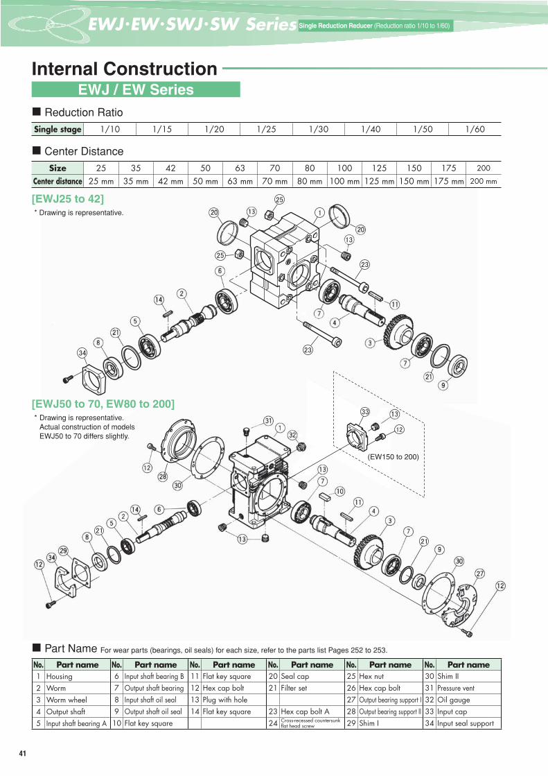
Internal ConstructionEWJ / EW Series
Reduction Ratio
Center Distance
[EWJ25 to 42]
[EWJ50 to 70, EW80 to 200]
Part Name For wear parts (bearings, oil seals) for each size, refer to the parts list Pages 252 to 253.
Single stage 1/10 1/15 1/20 1/25 1/30 1/40 1/50 1/60
Size 25 35 42 50 63 70 80 100 125 150 175 200
Center distance 25 mm 35 mm 42 mm 50 mm 63 mm 70 mm 80 mm 100 mm 125 mm 150 mm 175 mm 200 mm
No. Part name1 Housing2 Worm3 Worm wheel4 Output shaft5 Input shaft bearing A
No. Part name6 Input shaft bearing B7 Output shaft bearing8 Input shaft oil seal9 Output shaft oil seal10 Flat key square
No. Part name11 Flat key square12 Hex cap bolt13 Plug with hole14 Flat key square
No. Part name20 Seal cap21 Filter set
23 Hex cap bolt A24 Cross-recessed countersunk
fl at head screw
No. Part name25 Hex nut26 Hex cap bolt27 Output bearing support I28 Output bearing support II29 Shim I
No. Part name30 Shim II31 Pressure vent32 Oil gauge33 Input cap34 Input seal support
* Drawing is representative.Actual construction of models EWJ50 to 70 differs slightly.
* Drawing is representative.
42
EWJ
/ EW
/ SW
J / S
W S
erie
sSi
ngle
Red
uctio
n Ge
ar R
educ
ers
Spec
ifi ca
tions
3Eつばきウォーム減速機Tsubaki Worm Gear Reducer Search
Sing
le R
educ
tion
Gear
Red
ucer
sSi
ze42
Sing
le R
educ
tion
Gear
Red
ucer
sSi
ze50
Sing
le R
educ
tion
Gear
Red
ucer
sSi
ze63
Sing
le R
educ
tion
Gear
Red
ucer
sSi
ze70
Sing
le R
educ
tion
Gear
Red
ucer
sSi
ze80
Sing
le R
educ
tion
Gear
Red
ucer
sSi
ze10
0
Sing
le R
educ
tion
Gear
Red
ucer
sSi
ze12
5
Sing
le R
educ
tion
Gear
Red
ucer
sSi
ze15
0
Sing
le R
educ
tion
Gear
Red
ucer
sSi
ze17
5
Sing
le R
educ
tion
Gear
Red
ucer
sSi
ze20
0
Single
Red
uctio
n Ge
ar Re
duce
rsSiz
e25/3
5
12
(EWM150)
32
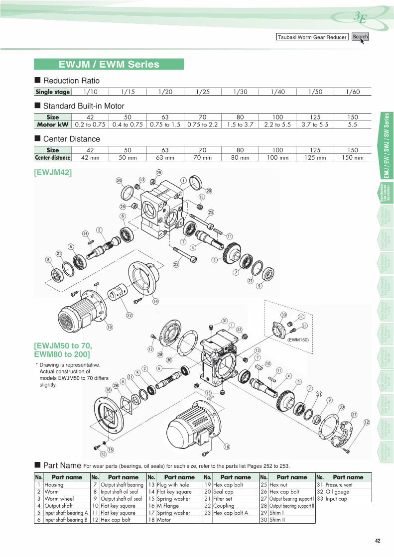
EWJM / EWM Series
Reduction Ratio
Standard Built-in Motor
Center Distance
[EWJM42]
[EWJM50 to 70,EWM80 to 200]
Part Name For wear parts (bearings, oil seals) for each size, refer to the parts list Pages 252 to 253.
Single stage 1/10 1/15 1/20 1/25 1/30 1/40 1/50 1/60
Size 42 50 63 70 80 100 125 150Motor kW 0.2 to 0.75 0.4 to 0.75 0.75 to 1.5 0.75 to 2.2 1.5 to 3.7 2.2 to 5.5 3.7 to 5.5 5.5
Size 42 50 63 70 80 100 125 150Center distance 42 mm 50 mm 63 mm 70 mm 80 mm 100 mm 125 mm 150 mm
No. Part name1 Housing2 Worm3 Worm wheel4 Output shaft5 Input shaft bearing A6 Input shaft bearing B
No. Part name7 Output shaft bearing8 Input shaft oil seal9 Output shaft oil seal
10 Flat key square11 Flat key square12 Hex cap bolt
No. Part name13 Plug with hole14 Flat key square15 Spring washer16 M Flange17 Spring washer18 Motor
No. Part name19 Hex cap bolt20 Seal cap21 Filter set22 Coupling23 Hex cap bolt A
No. Part name25 Hex nut26 Hex cap bolt27 Output bearing support I28 Output bearing support II29 Shim I30 Shim II
No. Part name31 Pressure vent32 Oil gauge33 Input cap
* Drawing is representative. Actual construction of
models EWJM50 to 70 differs slightly.

43
一段減速 (減速比1/10~1/60)Single Reduction Reducer (Reduction ratio 1/10 to 1/60)
Internal Construction
Reduction Ratio
Center Distance
Part Name For wear parts (bearings, oil seals) for each size, refer to the parts list Pages 252 to 253.
Single stage 1/10 1/15 1/20 1/25 1/30 1/40 1/50 1/60
Size 25 35 42 50 63 70 80 100 125 150 175 200
Center distance 25 mm 35 mm 42 mm 50 mm 63 mm 70 mm 80 mm 100 mm 125 mm 150 mm 175 mm 200 mm
No. Part name1 Housing2 Worm3 Integral output shaft with worm wheel
5 Input shaft bearing A
No. Part name6 Input shaft bearing B7 Output shaft bearing8 Input shaft oil seal9 Output shaft oil seal
No. Part name
12 Hex cap bolt13 Plug with hole14 Flat key square
No. Part name20 Seal cap21 Filter set
23 Hex cap bolt A24 Cross-recessed countersunk
fl at head screw
No. Part name25 Hex nut26 Hex cap bolt27 Output bearing support I
29 Shim I
No. Part name30 Shim II31 Pressure vent32 Oil gauge33 Input cap34 Input seal support
SWJ / SW Series
*Drawing is representative.
[SWJ50 to 70, SW80 to 200]* Drawing is representative. Actual
construction of models SWJ50 and 63 differs slightly.
* Drawing is representative.
[SWJ25 to 42]

44
EWJ
/ EW
/ SW
J / S
W S
erie
sSi
ngle
Red
uctio
n Ge
ar R
educ
ers
Spec
ifi ca
tions
3Eつばきウォーム減速機Tsubaki Worm Gear Reducer Search
Sing
le R
educ
tion
Gear
Red
ucer
sSi
ze42
Sing
le R
educ
tion
Gear
Red
ucer
sSi
ze50
Sing
le R
educ
tion
Gear
Red
ucer
sSi
ze63
Sing
le R
educ
tion
Gear
Red
ucer
sSi
ze70
Sing
le R
educ
tion
Gear
Red
ucer
sSi
ze80
Sing
le R
educ
tion
Gear
Red
ucer
sSi
ze10
0
Sing
le R
educ
tion
Gear
Red
ucer
sSi
ze12
5
Sing
le R
educ
tion
Gear
Red
ucer
sSi
ze15
0
Sing
le R
educ
tion
Gear
Red
ucer
sSi
ze17
5
Sing
le R
educ
tion
Gear
Red
ucer
sSi
ze20
0
Single
Red
uctio
n Ge
ar Re
duce
rsSiz
e25/3
5
Reduction Ratio
Standard Built-in Motor
Center Distance
Part Name For wear parts (bearings, oil seals) for each size, refer to the parts list Pages 252 to 253.
Single stage 1/10 1/15 1/20 1/25 1/30 1/40 1/50 1/60
Size 35 42 50 63 70 80 100 125 150Motor kW 0.2 0.2 to 0.4 0.4 to 0.75 0.75 to 1.5 0.75 to 2.2 1.5 to 3.7 2.2 to 5.5 3.7 to 5.5 5.5
Size 35 42 50 63 70 80 100 125 150Center distance 35 mm 42 mm 50 mm 63 mm 70 mm 80 mm 100 mm 125 mm 150 mm
No. Part name1 Housing2 Worm3 Integral output shaft with worm wheel
5 Input shaft bearing A6 Input shaft bearing B
No. Part name7 Output shaft bearing8 Input shaft oil seal9 Output shaft oil seal
10 Flat key square11 Flat key square12 Hex cap bolt
No. Part name13 Plug with hole14 Flat key square15 Spring washer16 M Flange17 Spring washer18 Motor
No. Part name19 Hex cap bolt20 Seal cap21 Filter set
23 Hex cap bolt A
No. Part name25 Hex nut26 Hex cap bolt27 Output bearing support I
29 Shim I30 Shim II
No. Part name31 Pressure vent32 Oil gauge33 Input cap
SWJM / SWM Series
* Drawing is representative.
12
[SWJM50 to 70, SWM80 to 200]* Drawing is representative. Actual
construction of models SWJM50 and 63 differs slightly.
[SWJM35 to 42]
45
一段減速 (減速比1/10~1/60)Single Reduction Reducer (Reduction ratio 1/10 to 1/60)
SizeInput 1750 r/min 1450 r/min 1150 r/min 950 r/min 500 r/min 100 r/min
ReductionRatio
Input Output torque Input Output torque Input Output torque Input Output torque Input Output torque Input Output torquekW N·m (kgf·m) kW N·m (kgf·m) kW N·m (kgf·m) kW N·m (kgf·m) kW N·m (kgf·m) kW N·m (kgf·m)
EWJ25
SWJ25
10 0.27 12.4 (1.26) 0.24 13.3 (1.36) 0.22 14.8 (1.51) 0.18 14.9 (1.52) 0.10 14.9 (1.52) 0.021 14.9 (1.52)
15 0.20 12.9 (1.31) 0.18 13.9 (1.41) 0.16 14.9 (1.52) 0.13 14.9 (1.52) 0.07 14.9 (1.52) 0.016 14.9 (1.52)
20 0.16 13.5 (1.38) 0.15 14.5 (1.48) 0.12 14.9 (1.52) 0.10 14.9 (1.52) 0.06 14.9 (1.52) 0.013 14.9 (1.52)
25 0.14 13.9 (1.42) 0.13 14.9 (1.52) 0.10 14.9 (1.52) 0.09 14.9 (1.52) 0.05 14.9 (1.52) 0.011 14.9 (1.52)
30 0.12 13.6 (1.39) 0.11 14.7 (1.50) 0.09 14.9 (1.52) 0.08 14.9 (1.52) 0.04 14.9 (1.52) 0.010 14.9 (1.52)
40 0.10 13.9 (1.42) 0.09 14.9 (1.52) 0.08 14.9 (1.52) 0.07 14.9 (1.52) 0.04 14.9 (1.52) 0.009 14.9 (1.52)
50 0.09 13.9 (1.42) 0.08 14.4 (1.47) 0.07 14.9 (1.52) 0.06 14.9 (1.52) 0.03 14.9 (1.52) 0.008 14.9 (1.52)
60 0.07 13.0 (1.33) 0.06 13.5 (1.37) 0.06 13.9 (1.42) 0.05 14.3 (1.46) 0.03 14.3 (1.46) 0.007 14.3 (1.46)
When running a speed within the shaded boxes , and also continuously for more than one hour, refer to the thermal rating factor on Page 21 to factor this into your selection.
Transfer Capacity Table
EWJ25E
Estimated mass 1.1 kg
φ45.6
□39
57
3090
98.56236.5
40 222015
φ10h7
71
3×3キーキー
77
7 7
4828
2535 M5タップM5タップ
深さ10深さ10
4-M6ボルト用-M6ボルト用貫通穴貫通穴
3×3 keyway
M5 tap, 10 deep
4-Through-hole for M6 bolts
88
50
2860 28
32
3020
3 3φ15h7
25 25
5×5キーキー5×5 keyway
88
50
28602832
3020
33
φ15h7
2525
5×5キー5×5 keyway
[L] [R]
Dimensional Drawings EWJ25E / SWJ25E
SWJ25E
Estimated mass 1.0 kg
3525
2848
77
77
3×3キー
71
φ10h715
202240
36.5 6298.5
9030
57
□39φ45.6
4-M6ボルト用貫通穴
3 x 3 keyway
4-Through-hole for M6 bolts
[DF]
φ20
φ20
325 25
3
6055 50
φ12H8
13.8
4Js9
φ2030°φ2030°
211821
φ13
11
Details of output shaft hole
*Refer to Page 29 for shaft arrangements and relative direction of rotation.*Tsubaki Emerson offers optional mounting bolts and mounting feet. Refer to Page 225.

46
3Eつばき PDF図面ライブラリーTSUBAKI EMERSON PDF Drawing Library Search
EWJ
/ EW
/ SW
J / S
W S
erie
s
*Tsubaki Emerson offers optional mounting bolts and mounting feet. Refer to Page 225.
Transfer Capacity Table
Size
Standard combination 1750 r/min 1450 r/min Values in ( ) for the motor indicates dimensions for a motor with a brake.
MotorkW
ReductionRatio
Output torque N·m (kgf·m)
Output torque N·m (kgf·m) MA MC MW1 MW MB MD MT
Estimatedmasskg
SWJM35 0.2
10 9.3 (0.95) 11.2 (1.14)212(229)
100(100)
312(329)
358(375)
140(140)
160(160)
81(104.5)
9.1(11)
15 13.4 (1.36) 15.9 (1.62)20 16.9 (1.73) 20.1 (2.05)25 20.4 (2.08) 24.2 (2.47)
* Motor/reducer combinations shown are standard.* Refer to Page 21 for sizing. * Thermal rating factor is 1.0.
[DF]SWJM35E
252025
130° φ
30
φ21
30°
φ30 22.8
1
φ20H8
6Js9
Details of output shaft hole
32.532.5MT
652.5
φ72h8
φ30
70
2.5 2.5
2.5
φ72h8
φ30
φMB
44
46
φMD
MA
MWMW1
φ80
MC
60.535.545
35
909.5 9.571
115
359.5
9.5
4-M8ボルト用貫通穴4-Through-hole for M8 bolts
Dimensional Drawings EWJ35E / SWJ35E / SWJM35E
SizeInput 1750 r/min 1450 r/min 1150 r/min 950 r/min 500 r/min 100 r/min
ReductionRatio
Input Output torque Input Output torque Input Output torque Input Output torque Input Output torque Input Output torquekW N·m (kgf·m) kW N·m (kgf·m) kW N·m (kgf·m) kW N·m (kgf·m) kW N·m (kgf·m) kW N·m (kgf·m)
EWJ35
SWJ35
10 0.59 27.6 (2.81) 0.53 29.7 (3.03) 0.49 33.8 (3.45) 0.44 36.5 (3.73) 0.24 37.3 (3.81) 0.053 37.3 (3.81)15 0.41 27.5 (2.81) 0.37 29.7 (3.03) 0.34 33.5 (3.42) 0.32 37.7 (3.85) 0.18 37.7 (3.85) 0.039 37.7 (3.85)20 0.33 27.8 (2.84) 0.30 30.0 (3.06) 0.27 33.7 (3.44) 0.26 37.7 (3.85) 0.14 37.7 (3.85) 0.032 37.7 (3.85)25 0.28 28.7 (2.93) 0.26 31.0 (3.16) 0.23 34.7 (3.54) 0.21 37.7 (3.85) 0.12 37.7 (3.85) 0.027 37.7 (3.85)30 0.25 29.3 (2.99) 0.23 31.6 (3.22) 0.21 35.3 (3.60) 0.19 37.7 (3.85) 0.11 37.7 (3.85) 0.025 37.7 (3.85)40 0.20 28.8 (2.94) 0.19 31.1 (3.18) 0.17 34.7 (3.54) 0.16 37.7 (3.85) 0.09 37.7 (3.85) 0.022 37.7 (3.85)50 0.18 29.6 (3.02) 0.16 31.9 (3.26) 0.15 35.5 (3.63) 0.14 37.7 (3.85) 0.08 37.7 (3.85) 0.019 37.7 (3.85)60 0.16 29.5 (3.01) 0.15 31.8 (3.25) 0.14 35.3 (3.61) 0.12 37.0 (3.78) 0.07 37.0 (3.78) 0.018 37.0 (3.78)
When running a speed within the shaded boxes , and also continuously for more than one hour, refer to the thermal rating factor on Page 21 to factor this into your selection.
SWJ35E
Estimated mass 1.9 kg
Estimated mass 9.1 kg (11 kg with brake)
252025
1
30° φ30
φ21
30°
φ30 22.8
1
φ20H8
6Js9
60.5
35.545
35
909.5 9.571
12346 77
50 272520
φ12h7
115
359.5
9.5
4×4キー
4-M8ボルト用貫通穴4-Through-hole for M8 bolts
4 x 4 keyway
Details of output shaft hole
[DF]
2.52.532.532.5
70
φ30
φ72h8
2.52.5 65
φ72h8
φ30
EWJ35E
Estimated mass 1.9 kg
φ47.6
□41
9.5
9.5
35115
φ12h720
252750
7746123
71 9.59.590
3545 35.5
60.5
4×4キー
M6タップ深さ12
4-M8ボルト用貫通穴
4 x 4 keyway
M6 tap, 12 deep4-Through-hole for M8 bolts
106
φ18h7
3434
38
3630
72
32.5 32.565
1.5 1.5
6×6キー6 x 6 keyway
106
φ18h7
3434
38
3630
72
32.532.565
1.51.5
6×6キー6 x 6 keyway
[L] [R]
*Refer to Page 29 for shaft arrangements and relative direction of rotation.
Single
Red
uctio
n Ge
ar Re
duce
rsSp
ecifi c
ation
s
Sing
le R
educ
tion
Gear
Red
ucer
sSi
ze42
Sing
le R
educ
tion
Gear
Red
ucer
sSi
ze50
Sing
le R
educ
tion
Gear
Red
ucer
sSi
ze63
Sing
le R
educ
tion
Gear
Red
ucer
sSi
ze70
Sing
le R
educ
tion
Gear
Red
ucer
sSi
ze80
Sing
le R
educ
tion
Gear
Red
ucer
sSi
ze10
0
Sing
le R
educ
tion
Gear
Red
ucer
sSi
ze12
5
Sing
le R
educ
tion
Gear
Red
ucer
sSi
ze15
0
Sing
le R
educ
tion
Gear
Red
ucer
sSi
ze17
5
Sing
le R
educ
tion
Gear
Red
ucer
sSi
ze20
0
Single
Red
uctio
n Ge
ar Re
duce
rsSiz
e25/3
5
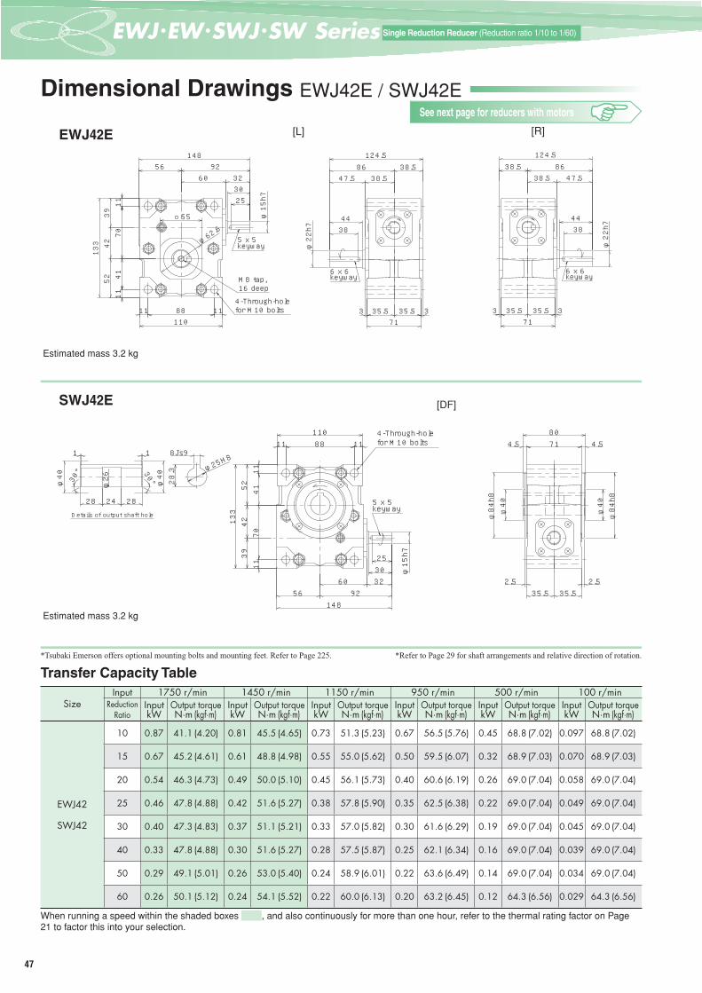
47
一段減速 (減速比1/10~1/60)Single Reduction Reducer (Reduction ratio 1/10 to 1/60)
SizeInput 1750 r/min 1450 r/min 1150 r/min 950 r/min 500 r/min 100 r/min
ReductionRatio
Input Output torque Input Output torque Input Output torque Input Output torque Input Output torque Input Output torquekW N·m (kgf·m) kW N·m (kgf·m) kW N·m (kgf·m) kW N·m (kgf·m) kW N·m (kgf·m) kW N·m (kgf·m)
EWJ42
SWJ42
10 0.87 41.1 (4.20) 0.81 45.5 (4.65) 0.73 51.3 (5.23) 0.67 56.5 (5.76) 0.45 68.8 (7.02) 0.097 68.8 (7.02)
15 0.67 45.2 (4.61) 0.61 48.8 (4.98) 0.55 55.0 (5.62) 0.50 59.5 (6.07) 0.32 68.9 (7.03) 0.070 68.9 (7.03)
20 0.54 46.3 (4.73) 0.49 50.0 (5.10) 0.45 56.1 (5.73) 0.40 60.6 (6.19) 0.26 69.0 (7.04) 0.058 69.0 (7.04)
25 0.46 47.8 (4.88) 0.42 51.6 (5.27) 0.38 57.8 (5.90) 0.35 62.5 (6.38) 0.22 69.0 (7.04) 0.049 69.0 (7.04)
30 0.40 47.3 (4.83) 0.37 51.1 (5.21) 0.33 57.0 (5.82) 0.30 61.6 (6.29) 0.19 69.0 (7.04) 0.045 69.0 (7.04)
40 0.33 47.8 (4.88) 0.30 51.6 (5.27) 0.28 57.5 (5.87) 0.25 62.1 (6.34) 0.16 69.0 (7.04) 0.039 69.0 (7.04)
50 0.29 49.1 (5.01) 0.26 53.0 (5.40) 0.24 58.9 (6.01) 0.22 63.6 (6.49) 0.14 69.0 (7.04) 0.034 69.0 (7.04)
60 0.26 50.1 (5.12) 0.24 54.1 (5.52) 0.22 60.0 (6.13) 0.20 63.2 (6.45) 0.12 64.3 (6.56) 0.029 64.3 (6.56)
When running a speed within the shaded boxes , and also continuously for more than one hour, refer to the thermal rating factor on Page 21 to factor this into your selection.
Dimensional Drawings EWJ42E / SWJ42E
EWJ42E
Estimated mass 3.2 kg
φ62.6
□55
25303260
9256148
88 1111110
4170
4239
52133
1111
φ15h7
5×5キー
M8タップ深さ164-M10ボルト用貫通穴
5 x 5 keyway
M8 tap, 16 deep4-Through-hole for M10 bolts
124.5
φ22h7 38
44
47.5 38.538.586
35.5 35.53 371
6×6キー6 x 6 keyway
124.5
φ22h738
44
47.538.538.5 86
35.535.5 3371
6×6キー6 x 6 keyway
[L] [R]
SWJ42E
Estimated mass 3.2 kg
28.330°30°
11
2828 24
φ26 φ40
φ40
8Js9
φ25H8
Details of output shaft hole
[DF]
φ84h8
φ40
35.5
φ84h8
φ40
4.54.58071
2.52.535.5
φ15h7
1111
133
5239
4270
41
11011 1188
14856 92
60 323025
5×5キー
4-M10ボルト用貫通穴4-Through-hole for M10 bolts
5 x 5 keyway
Transfer Capacity Table*Refer to Page 29 for shaft arrangements and relative direction of rotation.*Tsubaki Emerson offers optional mounting bolts and mounting feet. Refer to Page 225.
See next page for reducers with motors

48
3Eつばき PDF図面ライブラリーTSUBAKI EMERSON PDF Drawing Library Search
EWJ
/ EW
/ SW
J / S
W S
erie
s
Dimensional Drawings EWJM42E / SWJM42E
[R]
SWJM42E
EWJM42E
Size
Standard combination 1750 r/min 1450 r/min Values in ( ) for the motor indicates dimensions for a motor with a brake.
MotorkW
ReductionRatio
Output torque N·m (kgf·m)
Output torque N·m (kgf·m) MA MC MW1 MW MB MD MT
Estimatedmasskg
EWJM42
0.260 38.8 (3.96) 45.2 (4.62)
212(229)
130(130)
342(359)
398(415)
140(140)
160(160)
81(104.5)
11(13)50 34.2 (3.49) 40.0 (4.08)
40 29.0 (2.96) 34.1 (3.48)
0.4
30 47.3 (4.83) 51.1 (5.21)224(241)
130(130)
354(371)
410(427)
140(140)
160(160)
81(104.5)
12(14)
25 41.5 (4.23) 49.2 (5.02)20 34.4 (3.51) 40.8 (4.17)15 27.0 (2.76) 32.2 (3.29)
0.75 10 35.3 (3.60) 42.4 (4.30) 235(262)
140(140)
375(402)
431(458)
158(158)
200(200)
90(113.5)
18(21)
SWJM42
0.2
30 23.7 (2.42) 28.0 (2.85)212(229)
130(130)
342(359)
398(415)
140(140)
160(160)
81(104.5)
11(13)
40 29.0 (2.96) 34.1 (3.48)50 34.2 (3.49) 40.0 (4.08)60 38.8 (3.96) 45.2 (4.62)
0.4
10 18.8 (1.92) 22.5 (2.29)224(241)
130(130)
354(371)
410(427)
140(140)
160(160)
81(104.5)
12(14)
15 27.0 (2.76) 32.2 (3.29)20 34.4 (3.51) 40.8 (4.17)25 41.5 (4.23) 49.2 (5.02)
* Motor/reducer combinations shown are standard.* Shaded boxes indicate the motor capacity exceeds the input kW of the reducer. Confi rm output torque before using.* Refer to Page 21 for sizing. * Thermal rating factor is 1.0.
54MCMA
MW1MW
MT
φ62.6
□55
6×6キー6 x 6 keyway
56
8811 11110
4142
3952
133
1111
φ22h7MB
3844
47.5 38.538.586
35.5 35.53 371
124.5
M8タップ 深さ16M8 tap, 16 deep
70
φMD
4-M10ボルト用貫通穴4-Through-hole for M10 bolts
28.330°30°
11
2828 24
φ26 φ40
φ40
8Js9
φ25H8
Details of output shaft hole
[DF]
MA
MWMW1
MC54
MT
φMDφ84h8
φ40
35.5
φ84h8
φ40
4.54.58071
2.52.5
35.5
1111
13352
3942 70
41
11011 1188
56
φMB
4-M10ボルト用貫通穴4-Through-hole for M10 bolts
Transfer Capacity Table*Refer to Page 29 for shaft arrangements and relative direction of rotation.*Tsubaki Emerson offers optional mounting bolts and mounting feet. Refer to Page 225.
See previous page for reducers without motors
Single
Red
uctio
n Ge
ar Re
duce
rsSp
ecifi c
ation
s
Sing
le R
educ
tion
Gear
Red
ucer
sSi
ze42
Sing
le R
educ
tion
Gear
Red
ucer
sSi
ze50
Sing
le R
educ
tion
Gear
Red
ucer
sSi
ze63
Sing
le R
educ
tion
Gear
Red
ucer
sSi
ze70
Sing
le R
educ
tion
Gear
Red
ucer
sSi
ze80
Sing
le R
educ
tion
Gear
Red
ucer
sSi
ze10
0
Sing
le R
educ
tion
Gear
Red
ucer
sSi
ze12
5
Sing
le R
educ
tion
Gear
Red
ucer
sSi
ze15
0
Sing
le R
educ
tion
Gear
Red
ucer
sSi
ze17
5
Sing
le R
educ
tion
Gear
Red
ucer
sSi
ze20
0
Single
Red
uctio
n Ge
ar Re
duce
rsSiz
e 25/3
5

49
一段減速 (減速比1/10~1/60)Single Reduction Reducer (Reduction ratio 1/10 to 1/60)
Dimensional Drawings EWJ50E / EWJ50V / SWJ50E
[L] [R]
Estimated mass 7.0 kg
Estimated mass 7.6 kg
EWJ50E74
74 41115
189
6×6キー6 x 6 keyway
3038
φ19h7
112144
1616
M8タップ深さ16M8 tap, 16 deep
5080
68198
10652 54
8×7キー8 x 7 keyway
φ25h7 50
40
4-9穴4-φ9
11
11088
1111
54160
8×7キー
4-φ94-9穴11
1188110
11
4050
54 5210654
160
φ25h7
4-φ9
8 x 7 keyway
EWJ50V
SWJ50E
Estimated mass 11 kg
56 56112
φ45
φ100H7
φ138
5
2
5072
58180
7474 41115
189
φ19h730
38
φ45
φ100H7
φ138
5
2
6×6キー6 x 6 keyway
4-M8タップ深さ164-M8 tap, 16 deep(PCD120)
[DF]
出力軸穴部詳細Details of output shaft hole
8Js9
51.351.35535 38 35
φ31.4
φ45
1.5 1.5
30°
φ31
30°
φ45
φ31.4 φ3
0H8
33.3
SizeInput 1750 r/min 1450 r/min 1150 r/min 950 r/min 500 r/min 100 r/min
ReductionRatio
Input Output torque Input Output torque Input Output torque Input Output torque Input Output torque Input Output torquekW N·m (kgf·m) kW N·m (kgf·m) kW N·m (kgf·m) kW N·m (kgf·m) kW N·m (kgf·m) kW N·m (kgf·m)
EWJ50
10 1.70 84 (8.6) 1.54 91 ( 9.3) 1.34 99 (10.1) 1.20 106 (10.9) 0.67 109 (11.1) 0.14 109 (11.1)15 1.28 91 (9.3) 1.16 99 (10.1) 1.03 109 (11.1) 0.86 109 (11.1) 0.47 109 (11.1) 0.10 109 (11.1)20 1.02 94 (9.6) 0.92 101 (10.4) 0.80 109 (11.1) 0.67 109 (11.1) 0.37 109 (11.1) 0.08 109 (11.1)25 0.85 95 (9.7) 0.76 101 (10.3) 0.66 108 (11.1) 0.56 109 (11.1) 0.31 109 (11.1) 0.07 109 (11.1)30 0.75 95 (9.7) 0.68 103 (10.5) 0.59 109 (11.1) 0.50 109 (11.1) 0.28 109 (11.1) 0.07 109 (11.1)40 0.59 94 (9.6) 0.53 101 (10.3) 0.47 108 (11.1) 0.40 109 (11.1) 0.22 109 (11.1) 0.05 109 (11.1)50 0.48 91 (9.3) 0.43 98 (10.0) 0.38 104 (10.6) 0.34 109 (11.1) 0.19 109 (11.1) 0.05 109 (11.1)60 0.40 86 (8.8) 0.36 92 ( 9.4) 0.32 98 (10.0) 0.28 103 (10.5) 0.17 106 (10.8) 0.04 106 (10.8)
SWJ50
10 1.56 77 (7.9) 1.40 83 ( 8.5) 1.28 94 ( 9.6) 1.15 102 (10.4) 0.67 109 (11.1) 0.14 109 (11.1)15 1.13 81 (8.2) 1.02 87 ( 8.9) 0.89 94 ( 9.6) 0.78 99 (10.1) 0.47 109 (11.1) 0.10 109 (11.1)20 0.91 84 (8.6) 0.82 91 ( 9.2) 0.71 97 ( 9.9) 0.63 102 (10.4) 0.37 109 (11.1) 0.08 109 (11.1)25 0.77 86 (8.8) 0.69 92 ( 9.4) 0.58 96 ( 9.8) 0.51 101 (10.3) 0.31 109 (11.1) 0.07 109 (11.1)30 0.65 83 (8.5) 0.60 90 ( 9.2) 0.52 97 ( 9.9) 0.46 102 (10.4) 0.28 109 (11.1) 0.06 109 (11.1)40 0.52 84 (8.5) 0.47 90 ( 9.1) 0.41 96 ( 9.8) 0.36 101 (10.3) 0.22 109 (11.1) 0.05 109 (11.1)50 0.42 81 (8.2) 0.38 86 ( 8.8) 0.34 92 ( 9.4) 0.30 97 ( 9.9) 0.19 109 (11.1) 0.05 109 (11.1)60 0.37 80 (8.2) 0.34 86 ( 8.7) 0.29 91 ( 9.3) 0.26 95 ( 9.7) 0.17 105 (10.7) 0.04 106 (10.8)
When running a speed within the shaded boxes , and also continuously for more than one hour, refer to the thermal rating factor on Page 21 to factor this into your selection.
Transfer Capacity Table*Refer to Page 29 for shaft arrangements and relative direction of rotation.
φ19h738
30
6×6キー6 x 6 keyway
12013 13146
74189
11574 41
M8タップ深さ16M8 tap, 16 deep
106
40 50
φ25h768
198
538413
13 4-9穴4-φ9
5452
82
80508×7キー8 x 7 keyway
11
163
188
198
φ25h78×7キー
5384 1313
4050
4-9穴
5482
24106
50
11
163
68 80
160
4-φ98 x 7 keyway
[RU] [RD]
See next page for reducers with motors

50
3Eつばき PDF図面ライブラリーTSUBAKI EMERSON PDF Drawing Library Search
EWJ
/ EW
/ SW
J / S
W S
erie
s
Dimensional Drawings EWJM50E / EWJM50V / SWJM50E
EWJM50VEWJM50E
5040
11
198
68
1111 881104-9穴
8050
φ25h7
8×7キー
106
16 112
74
M8タップ深さ16M8 tap, 16 deep
16144
MTMA
12
φMD
MB
91
MWMW1
16054
5452
8 x 7 keyway
4-φ9
11
50 80
8252
54
4-9穴
74
1461313 120 13 13
16384 53
19868
φ25h78×7キー
5040
106
MB
φMD
MT12
188
91MAMW1
MWM8タップ深さ16M8 tap, 16 deep
8 x 7 keyway
4-φ9
[R] [LU]
φ100H7
φ138
5656
MWMW1
MAMC
φMB
112
φ45
φ100H7
φ138
52
5072
58180
74
52
4-M8タップ 深さ164-M8 tap, 16 deep(PCD120)
8Js9
51.351.35535 38 35
φ31.4
1.5 1.5
30°
φ31
30°
φ45
φ31.4 φ3
0H8
33.3
φ45
φ45
φMD出力軸穴部詳細Details of output shaft hole
SWJM50E
[DF]
Size
Standard combination 1750 r/min 1450 r/min Values in ( ) for the motor indicates dimensions for a motor with a brake.
MotorkW
ReductionRatio
Output torque N·m (kgf·m)
Output torque N·m (kgf·m) MA MC MW1 MW MB MD MT
E typeEstimated mass
kg
V typeEstimated mass
kg
EWJM50
0.440 65 (6.6) 76 ( 7.8)
224(241) – 315
(332)389(406)
140(140)
160(160)
81(104.5)
15(17)
15(17)50 76 (7.8) 90 ( 9.2)
60 86 (8.8) 92 ( 9.4)
0.75
10 37 (3.8) 44 ( 4.5)
235(262) – 328
(355)402(429)
158(158)
200(200)
90(113.5)
19(22)
19(22)
15 53 (5.5) 64 ( 6.5)20 69 (7.1) 83 ( 8.4)25 84 (8.6) 100 (10.2)30 95 (9.7) 103 (10.5)
SWJM500.4
20 37 (3.8) 44 ( 4.5)
224(241)
148(148)
372(389)
446(463)
140(140)
160(160)
81(104.5)
21(23) –
25 45 (4.6) 53 ( 5.4)30 51 (5.2) 60 ( 6.1)40 65 (6.6) 76 ( 7.8)50 76 (7.8) 86 ( 8.8)60 80 (8.2) 86 ( 8.8)
0.75 10 37 (3.8) 44 ( 4.5) 235(262)
158(158)
393(420)
467(494)
158(158)
200(200)
90(113.5)
25(28) –15 53 (5.5) 64 ( 6.5)
* Motor/reducer combinations shown are standard.* Shaded boxes indicate the motor capacity exceeds the input kW of the reducer. Confi rm output torque before using.* Refer to Page 21 for sizing. * Thermal rating factor is 1.0.
Transfer Capacity Table*Refer to Page 29 for shaft arrangements and relative direction of rotation.
See previous page for reducers without motors
Single
Red
uctio
n Ge
ar Re
duce
rsSp
ecifi c
ation
s
Single
Red
uctio
n Ge
ar Re
duce
rsSiz
e 42
Sing
le R
educ
tion
Gear
Red
ucer
sSi
ze50
Sing
le R
educ
tion
Gear
Red
ucer
sSi
ze63
Sing
le R
educ
tion
Gear
Red
ucer
sSi
ze70
Sing
le R
educ
tion
Gear
Red
ucer
sSi
ze80
Sing
le R
educ
tion
Gear
Red
ucer
sSi
ze10
0
Sing
le R
educ
tion
Gear
Red
ucer
sSi
ze12
5
Sing
le R
educ
tion
Gear
Red
ucer
sSi
ze15
0
Sing
le R
educ
tion
Gear
Red
ucer
sSi
ze17
5
Sing
le R
educ
tion
Gear
Red
ucer
sSi
ze20
0
Single
Red
uctio
n Ge
ar Re
duce
rsSiz
e 25/3
5

51
一段減速 (減速比1/10~1/60)Single Reduction Reducer (Reduction ratio 1/10 to 1/60)
Dimensional Drawings EWJ63E / EWJ63V / SWJ63E
EWJ63E
Estimated mass 11 kg
EWJ63V
Estimated mass 12 kg
174
90 52
23290
19 136 19
4050
φ25h7
142
M10タップ深さ20M10 tap, 20 deep
7863
98239 8×7キー
8
8 x 7 keyway
8
8×7キー8 x 7 keyway
4050
φ25h7
144 1616176
90 142232
5290
M10タップ深さ20M10 tap, 20 deep
12463
5060
φ30h7
10411 11126
13
4-11穴4-φ11
61
8×7キー
61185
4
8 x 7 keyway
φ30h7
126
61
8×7キー
13
11 11104
6050
63124
4-11穴
61185
4-φ11
8 x 7 keyway
[L] [R]
611246350 60
8×7キーφ30h7986378
239
6416
16197
9513
101219
4-11穴4-φ11
8 x 7 keyway
8×7キー 4-11穴
61
78239
64 1616 101197
95
5060 29124
13
9863
185
φ30h7 4-φ118 x 7
keyway
[RU] [RD]
SWJ63E
66 66132
5
2
φ48
φ165
5
2φ48
φ120H7
φ120H7
φ165
φ48
φ48
10Js9
38.3 φ3
5H8
φ37
φ36 30°
1.65 6
2
40
φ37
40
30°
1.656
2
48
出力軸穴部詳細Details of output shaft hole φ25h7
6387
70220
9090 52142
232
4050
8×7キー8 x 7 keyway
4-M10タップ深さ184-M10 tap, 18 deep(PCD145)
[DF]
Estimated mass 16 kg
SizeInput 1750 r/min 1450 r/min 1150 r/min 950 r/min 500 r/min 100 r/min
ReductionRatio
Input Output torque Input Output torque Input Output torque Input Output torque Input Output torque Input Output torquekW N·m (kgf·m) kW N·m (kgf·m) kW N·m (kgf·m) kW N·m (kgf·m) kW N·m (kgf·m) kW N·m (kgf·m)
EWJ63
10 3.22 161 (16.4) 2.98 178 (18.2) 2.65 197 (20.1) 2.36 211 (21.6) 1.36 224 (22.9) 0.29 224 (22.9)15 2.41 174 (17.7) 2.23 192 (19.6) 1.98 212 (21.6) 1.75 224 (22.9) 0.96 224 (22.9) 0.21 224 (22.9)20 1.91 179 (18.2) 1.76 196 (20.0) 1.56 215 (22.0) 1.36 224 (22.9) 0.75 224 (22.9) 0.17 224 (22.9)25 1.57 179 (18.3) 1.44 196 (20.0) 1.27 213 (21.7) 1.12 224 (22.9) 0.62 224 (22.9) 0.14 224 (22.9)30 1.38 180 (18.4) 1.29 198 (20.2) 1.15 218 (22.3) 1.00 224 (22.9) 0.56 224 (22.9) 0.13 224 (22.9)40 1.09 178 (18.2) 1.01 196 (20.0) 0.91 215 (21.9) 0.80 224 (22.9) 0.46 224 (22.9) 0.11 224 (22.9)50 0.88 173 (17.7) 0.81 188 (19.2) 0.73 205 (20.9) 0.65 217 (22.1) 0.39 224 (22.9) 0.09 224 (22.9)60 0.72 163 (16.7) 0.67 177 (18.1) 0.59 192 (19.6) 0.53 203 (20.7) 0.31 204 (20.8) 0.07 204 (20.8)
SWJ63
10 2.70 135 (13.7) 2.43 145 (14.8) 2.20 164 (16.8) 1.99 178 (18.1) 1.36 224 (22.9) 0.29 224 (22.9) 15 1.95 140 (14.3) 1.76 152 (15.5) 1.59 170 (17.4) 1.44 184 (18.8) 0.96 224 (22.9) 0.21 224 (22.9) 20 1.56 145 (14.8) 1.41 157 (16.0) 1.28 176 (17.9) 1.16 190 (19.4) 0.75 224 (22.9) 0.17 224 (22.9) 25 1.32 151 (15.4) 1.20 163 (16.6) 1.08 182 (18.5) 0.99 197 (20.1) 0.62 224 (22.9) 0.14 224 (22.9) 30 1.13 147 (15.0) 1.03 158 (16.2) 0.93 177 (18.0) 0.85 191 (19.5) 0.56 224 (22.9) 0.13 224 (22.9) 40 0.92 150 (15.3) 0.84 163 (16.6) 0.76 181 (18.5) 0.70 196 (20.0) 0.46 224 (22.9) 0.11 224 (22.9) 50 0.79 155 (15.8) 0.72 168 (17.1) 0.66 186 (19.0) 0.61 202 (20.6) 0.39 224 (22.9) 0.09 224 (22.9) 60 0.70 158 (16.2) 0.64 171 (17.5) 0.59 190 (19.4) 0.52 200 (20.4) 0.31 204 (20.8) 0.07 204 (20.8)
When running a speed within the shaded boxes , and also continuously for more than one hour, refer to the thermal rating factor on Page 21 to factor this into your selection.
Transfer Capacity Table*Refer to Page 29 for shaft arrangements and relative direction of rotation.
See next page for reducers with motors

52
3Eつばき PDF図面ライブラリーTSUBAKI EMERSON PDF Drawing Library Search
EWJ
/ EW
/ SW
J / S
W S
erie
s
Dimensional Drawings EWJM63E / EWJM63V / SWJM63E
EWJM63E EWJM63V
4-11穴4-φ11 104 1111126
19 136 19174
MB
MA
φMD
61
M10タップ深さ20M10 tap, 20 deep 13
60φ30h7
50
6378
98239
63124
14
90108
MW1MW
61185
MT
8×7キー8 x 7 keyway
611246350 60
988×7キー8 x 7 keywayφ30h7
6378239
64 1616197
9513
4-11穴4-φ1114416 16176
90
MB
MA
φMD 14
101
219
108MW1
MW
MT
M10タップ深さ20M10 tap, 20 deep
[R] [LU]
SWJM63E
出力軸穴部詳細Details of output shaft hole
φ48
φ48φ37
22
486 1.65
30°
40
φ37
4061.65
30°
φ36
10Js9
38.3 φ3
5H8
[DF]
φ120H7
φ165
6666132
5
2
φ120H7
φ165
5
2
φ48
φ48
MTMC
6387
70
90
4-M10タップ 深さ184-M10 tap, 18 deep(PCD145)
220
φMB
MAMW1
MW
φMD
Size
Standard combination 1750 r/min 1450 r/min Values in ( ) for the motor indicates dimensions for a motor with a brake.
MotorkW
ReductionRatio
Output torque N·m (kgf·m)
Output torque N·m (kgf·m) MA MC MW1 MW MB MD MT
E typeEstimated mass
kg
V typeEstimated mass
kg
EWJM63
0.7540 123 (12.6) 145 (14.8)
235(262) – 343
(370)433(460)
158(158)
200(200)
90(113.5)
23(26)
24(27)50 147 (15.0) 174 (17.7)
60 163 (16.7) 177 (18.1)
1.5
10 75 ( 7.6) 90 ( 9.1)
274(328) – 382
(436)472(526)
198(198)
200(200)
151(149)
31(36)
32(37)
15 108 (11.0) 129 (13.2)20 140 (14.3) 167 (17.0)25 171 (17.4) 196 (20.0)30 180 (18.4) 198 (20.2)
SWJM630.75
20 70 ( 7.1) 83 ( 8.5)
235(262)
185(185)
420(447)
510(537)
158(158)
200(200)
90(113.5)
31(34) –
25 85 ( 8.7) 102 (10.4) 30 98 ( 9.9) 115 (11.8) 40 123 (12.6) 145 (14.8) 50 147 (15.0) 168 (17.1) 60 158 (16.2) 171 (17.5)
1.5 10 75 ( 7.6) 90 ( 9.1) 274(328)
185(185)
459(513)
549(603)
198(198)
200(200)
151(149)
39(44) -–15 108 (11.0) 129 (13.2)
* Motor/reducer combinations shown are standard.* Shaded boxes indicate the motor capacity exceeds the input kW of the reducer. Confi rm output torque before using.* Refer to Page 21 for sizing. * Thermal rating factor is 1.0.
Transfer Capacity Table*Refer to Page 29 for shaft arrangements and relative direction of rotation.
See previous page for reducers without motors
Single
Red
uctio
n Ge
ar Re
duce
rsSp
ecifi c
ation
s
Single
Red
uctio
n Ge
ar Re
duce
rsSiz
e 42
Single
Red
uctio
n Ge
ar Re
duce
rsSiz
e 50
Sing
le R
educ
tion
Gear
Red
ucer
sSi
ze63
Sing
le R
educ
tion
Gear
Red
ucer
sSi
ze70
Sing
le R
educ
tion
Gear
Red
ucer
sSi
ze80
Sing
le R
educ
tion
Gear
Red
ucer
sSi
ze10
0
Sing
le R
educ
tion
Gear
Red
ucer
sSi
ze12
5
Sing
le R
educ
tion
Gear
Red
ucer
sSi
ze15
0
Sing
le R
educ
tion
Gear
Red
ucer
sSi
ze17
5
Sing
le R
educ
tion
Gear
Red
ucer
sSi
ze20
0
Single
Red
uctio
n Ge
ar Re
duce
rsSiz
e 25/3
5

53
一段減速 (減速比1/10~1/60)Single Reduction Reducer (Reduction ratio 1/10 to 1/60)
Dimensional Drawings EWJ70E / EWJ70V / SWJ70E
EWJ70E
Estimated mass 13 kg
EWJ70V
Estimated mass 14.6 kg
[L] [R]
[RU] [RD]
SWJ70E
Estimated mass 21 kg
SizeInput 1750 r/min 1450 r/min 1150 r/min 950 r/min 500 r/min 100 r/min
ReductionRatio
Input Output torque Input Output torque Input Output torque Input Output torque Input Output torque Input Output torquekW N·m (kgf·m) kW N·m (kgf·m) kW N·m (kgf·m) kW N·m (kgf·m) kW N·m (kgf·m) kW N·m (kgf·m)
EWJ70
10 4.28 214 (21.9) 3.85 231 (23.6) 3.51 263 (26.8) 3.16 284 (29.0) 1.96 324 (33.1) 0.42 324 (33.1)15 3.09 225 (22.9) 2.80 242 (24.7) 2.54 273 (27.9) 2.29 295 (30.1) 1.38 324 (33.1) 0.30 324 (33.1)20 2.50 235 (24.0) 2.26 254 (25.9) 2.05 285 (29.1) 1.86 309 (31.5) 1.08 324 (33.1) 0.24 324 (33.1)25 2.12 243 (24.8) 1.92 263 (26.8) 1.74 294 (30.0) 1.56 314 (32.0) 0.89 324 (33.1) 0.20 324 (33.1)30 1.80 236 (24.0) 1.64 255 (26.0) 1.49 284 (29.0) 1.36 308 (31.4) 0.81 324 (33.1) 0.19 324 (33.1)40 1.45 241 (24.6) 1.35 265 (27.0) 1.22 295 (30.1) 1.11 315 (32.2) 0.65 324 (33.1) 0.15 324 (33.1)50 1.18 235 (23.9) 1.10 258 (26.3) 0.99 283 (28.9) 0.89 302 (30.8) 0.55 324 (33.1) 0.13 324 (33.1)60 0.97 222 (22.7) 0.90 243 (24.8) 0.81 266 (27.1) 0.73 282 (28.8) 0.46 311 (31.7) 0.11 311 (31.8)
SWJ70
10 3.14 157 (16.0) 2.94 176 (18.0) 2.62 196 (20.0) 2.35 211 (21.6) 1.62 268 (27.4) 0.39 300 (30.6) 15 2.43 176 (18.0) 2.27 197 (20.1) 1.95 210 (21.5) 1.76 227 (23.1) 1.18 276 (28.1) 0.30 317 (32.3) 20 2.03 191 (19.5) 1.94 217 (22.2) 1.63 227 (23.1) 1.48 245 (25.0) 0.92 277 (28.2) 0.23 310 (31.6) 25 1.71 196 (20.0) 1.56 213 (21.7) 1.38 233 (23.8) 1.25 252 (25.7) 0.72 263 (26.8) 0.19 301 (30.7) 30 1.45 190 (19.4) 1.36 212 (21.6) 1.24 236 (24.1) 1.12 254 (25.9) 0.71 283 (28.9) 0.18 317 (32.3) 40 1.20 200 (20.4) 1.13 222 (22.7) 1.00 242 (24.7) 0.91 259 (26.4) 0.58 292 (29.8) 0.15 316 (32.2) 50 0.97 194 (19.8) 0.91 214 (21.8) 0.81 233 (23.7) 0.73 248 (25.3) 0.46 273 (27.9) 0.12 294 (30.0) 60 0.80 184 (18.8) 0.75 201 (20.6) 0.66 218 (22.3) 0.60 232 (23.6) 0.38 253 (25.9) 0.10 276 (28.2)
When running a speed within the shaded boxes , and also continuously for more than one hour, refer to the thermal rating factor on Page 21 to factor this into your selection.
1914219180
5040
53
24194
94147
φ25h7
8×7キー8 x 7 keyway
M10タップ深さ20M10 tap, 20 deep
14794
241
5394
4050
φ25h7
8×7キー8 x 7 keyway
152 17186
17
M10タップ深さ20M10 tap, 20 deep
20062
62138
76
7055
15
13214 14104
250
100
7080
φ35h7
4-14穴4-φ14
10×8キー10 x 8 keyway
φ35h7
4-14穴4-φ14
10×8キー10 x 8 keyway
250
20062
6213876
7055
15
1321414 104
100
7080
15 104
242
67106207
1717
7055
2501007080
10×8キー10 x 8 keyway
6276
138
φ35h7
4-14穴4-φ14
10×8キー10 x 8 keyway
φ35h7 4-14穴4-φ14
15
20062
138
34104
100
70 55
2507080
207176710617
5042
25h7
240
7870
92
277112 165 6-M8タップ
深さ15
8×7キー8 x 7 keyway
113 526-M8 tap, 15 deep(PCD157)
40H812Js9
43.341
1.95 7
45
42.5
58
2
1.957
4045
30° 30°42.5
58
2
出力軸穴部詳細Details of output shaft hole
5
5
58137H7
177
135
6570
[LF]
Transfer Capacity Table*Refer to Page 29 for shaft arrangements and relative direction of rotation.
See next page for reducers with motors

54
3Eつばき PDF図面ライブラリーTSUBAKI EMERSON PDF Drawing Library Search
EWJ
/ EW
/ SW
J / S
W S
erie
s
Dimensional Drawings EWJM70E / EWJM70V / SWJM70E
Size
Standard combination 1750 r/min 1450 r/min Values in ( ) for the motor indicates dimensions for a motor with a brake.
MotorkW
ReductionRatio
Output torque N·m (kgf·m)
Output torque N·m (kgf·m) MA MC MW1 MW MB MD MT
E typeEstimated mass
kg
V typeEstimated mass
kg
EWJM70
0.7540 125 (12.7) 148 (15.1)
235(262) – 349
(376)443(470)
158(158)
200(200)
90(113.5)
25(28)
26(29)50 150 (15.3) 176 (18.0)
60 172 (17.6) 203 (20.7)
1.5 25 172 (17.6) 205 (20.9) 274(328) – 388
(442)482(536)
198(198)
200(200)
151(149)
33(38)
34(39)30 197 (20.1) 233 (23.8)
2.210 110 (11.2) 132 (13.5)
278(332) – 392
(446)486(540)
198(198)
250(250)
143(141)
38(43)
40(45)15 160 (16.3) 191 (19.4)
20 207 (21.1) 247 (25.2)
SWJM70
0.75
30 98 (10.0) 116 (11.9) 235(262)
198(198)
433(460)
545(572)
158(158)
200(200)
90(113.5)
39(42) –40 125 (12.7) 148 (15.1)
50 150 (15.3) 176 (18.0) 60 172 (17.6) 201 (20.6)
1.515 109 (11.1) 130 (13.3)
274(328)
198(198)
472(526)
584(638)
198(198)
200(200)
151(149)
47(52) –20 141 (14.4) 168 (17.2)
25 172 (17.6) 205 (20.9)
2.2 10 110 (11.2) 132 (13.5) 278(332)
222(222)
500(554)
612(666)
198(198)
250(250)
143(141)
52(57) –
* Motor/reducer combinations shown are standard.* Shaded boxes indicate the motor capacity exceeds the input kW of the reducer. Confi rm output torque before using.* Refer to Page 21 for sizing. * Thermal rating factor is 1.0.
EWJM70E EWJM70V
MWMW1
MA
MB
14
φMD
94114
20062
62
φ35h7
1387670
55
1914219180
15
13214104
250
100
7080
M10M10タップタップ深さ20深さ20M10 tap, 20 deep
10×810×8キーキー10×8 keyway
4-14 14 穴4-φ14
MT
4-14穴
MWMW1
11494
MA
MB
14
φMD
24213876
62
7055
15
1861717 152
207176717 106
104
1002507080
10×8キー10×8 keyway
φ35h7
4-14穴4-φ14
MT
M10タップ 深さ20M10 tap, 20 deep
[R] [LU]
SWJM70E
5
5
φ58
φ137H7
φ177
13565 70
MT
φ40H812Js9
43.3
φ41
1.95 745
30°
φ42.5
φ58
2
1.9574045
30°
φ42.5
φ58
2
Details of output shaft hole
MWMW1
MA
φMB
112MC
φMD
240
7870
92
6-M8タップ 深さ156-M8 tap, 15 deep(PCD157)
[LF]
Transfer Capacity Table*Refer to Page 29 for shaft arrangements and relative direction of rotation.
See previous page for reducers without motors
Single
Red
uctio
n Ge
ar Re
duce
rsSp
ecifi c
ation
s
Single
Red
uctio
n Ge
ar Re
duce
rsSiz
e 42
Single
Red
uctio
n Ge
ar Re
duce
rsSiz
e 50
Single
Red
uctio
n Ge
ar Re
duce
rsSiz
e 63
Sing
le R
educ
tion
Gear
Red
ucer
sSi
ze70
Sing
le R
educ
tion
Gear
Red
ucer
sSi
ze80
Sing
le R
educ
tion
Gear
Red
ucer
sSi
ze10
0
Sing
le R
educ
tion
Gear
Red
ucer
sSi
ze12
5
Sing
le R
educ
tion
Gear
Red
ucer
sSi
ze15
0
Sing
le R
educ
tion
Gear
Red
ucer
sSi
ze17
5
Sing
le R
educ
tion
Gear
Red
ucer
sSi
ze20
0
Single
Red
uctio
n Ge
ar Re
duce
rsSiz
e 25/3
5

55
一段減速 (減速比1/10~1/60)Single Reduction Reducer (Reduction ratio 1/10 to 1/60)
Dimensional Drawings EW80T / EW80B / EW80V
EW80T
Estimated mass 28 kg
EW80B
Estimated mass 27 kg
EW80V
Estimated mass 30 kg
SizeInput 1750 r/min 1450 r/min 1150 r/min 950 r/min 500 r/min 100 r/min
ReductionRatio
Input Output torque Input Output torque Input Output torque Input Output torque Input Output torque Input Output torquekW N·m (kgf·m) kW N·m (kgf·m) kW N·m (kgf·m) kW N·m (kgf·m) kW N·m (kgf·m) kW N·m (kgf·m)
EW80
10 6.52 329 (33.6) 6.16 372 (38.0) 5.52 417 (42.5) 4.86 441 (45.0) 2.83 474 (48.3) 0.61 474 (48.3)
15 4.88 358 (36.5) 4.53 397 (40.5) 3.98 434 (44.3) 3.52 459 (46.9) 1.98 473 (48.3) 0.44 474 (48.3)
20 3.88 370 (37.7) 3.62 412 (42.0) 3.18 449 (45.8) 2.80 473 (48.3) 1.55 473 (48.3) 0.34 473 (48.3)
25 3.21 374 (38.1) 2.99 414 (42.3) 2.67 460 (46.9) 2.31 474 (48.3) 1.28 474 (48.3) 0.29 474 (48.3)
30 2.77 371 (37.9) 2.62 416 (42.4) 2.30 451 (46.0) 2.03 474 (48.3) 1.14 474 (48.3) 0.27 474 (48.3)
40 2.17 370 (37.8) 2.05 413 (42.2) 1.86 461 (47.0) 1.62 473 (48.3) 0.92 473 (48.3) 0.22 474 (48.3)
50 1.76 361 (36.8) 1.66 400 (40.8) 1.50 443 (45.2) 1.36 473 (48.3) 0.78 474 (48.3) 0.19 474 (48.3)
60 1.44 342 (34.9) 1.35 376 (38.4) 1.21 414 (42.3) 1.07 429 (43.8) 0.62 429 (43.8) 0.15 430 (43.8)
When running a speed within the shaded boxes , and also continuously for more than two hours, refer to the thermal rating factor on Page 21 to factor this into your selection.
Transfer Capacity Table*Refer to Page 29 for shaft arrangements and relative direction of rotation.
[L] [R] [H]
16517.5 17.5200
177100277
120 57
φ25h7
8580
110
275
15 15114144
17
4555
7474148
φ70
オイルゲージOil gauge
ドレンプラグDrain plug
4-14キリ4-φ14
8×7キー
プレッシャベントPressure vent
8×7キー8×7keyway
8×7keyway
10 x 8keyway
10 x 8keyway
2-M8タップ 深さ162-M8 tap, 16 deep
プレッシャベントPressure vent
ドレンプラグDrain plug
4-φ14 4-φ14 16517.5 17.5200
177100277
120 57
20
4555
オイルゲージOil gauge
φ25h7
3
5048502.2
3
2.2 88
φ70
14Js9
53.8 φ5
0H8
φ51
φ70 30°φ53 30°
φ53
出力軸穴部詳細Details of output shaft hole
[L] [R] [H]
16517.5 17.5200
177100277
120 57
5545オイルゲージ
8×7キー
Pressure vent Pressure vent
2-M8 tap,16 deep
Oil gauge
Oil gauge
Drain plug
Drain plug8 x 7 keyway
8 x 7 keyway
10 x 8 keyway 10 x 8
keyway
4-φ14 4-φ14 4-φ14
φ25h7
8580
110
275
15 15114144
74
17
74148
φ70
3
5048502.2
3
2.2 88
φ70
14Js9
53.8 φ5
0H8
φ51
φ70 30°φ53 30°
φ53
出力軸穴部詳細Details of output shaft hole
120 57
[RU]
120 57
20
2-M8タップ深さ162-M8 tap, 16 deep
Oil gauge
Pressure vent
4-φ15
4-φ15
Pressure vent
10 x 8 keyway
10 x 8 keyway
Drain plug
8 x 7 keyway
[RD]

56
3Eつばき PDF図面ライブラリーTSUBAKI EMERSON PDF Drawing Library Search
EWJ
/ EW
/ SW
J / S
W S
erie
s
Dimensional Drawings SW80T / SW80B / SW80V
SW80T
Estimated mass 26 kg
SW80B
Estimated mass 26 kg
SW80V
Estimated mass 26 kg
SizeInput 1750 r/min 1450 r/min 1150 r/min 950 r/min 500 r/min 100 r/min
ReductionRatio
Input Output torque Input Output torque Input Output torque Input Output torque Input Output torque Input Output torquekW N·m (kgf·m) kW N·m (kgf·m) kW N·m (kgf·m) kW N·m (kgf·m) kW N·m (kgf·m) kW N·m (kgf·m)
SW80
10 6.52 329 (33.6) 6.16 372 (38.0) 5.52 417 (42.5) 4.86 441 (45.0) 2.83 474 (48.3) 0.61 474 (48.3)
15 4.88 358 (36.5) 4.53 397 (40.5) 3.98 434 (44.3) 3.52 459 (46.9) 1.98 473 (48.3) 0.44 474 (48.3)
20 3.88 370 (37.7) 3.62 412 (42.0) 3.18 449 (45.8) 2.80 473 (48.3) 1.55 473 (48.3) 0.34 473 (48.3)
25 3.21 374 (38.1) 2.99 414 (42.3) 2.67 460 (46.9) 2.31 474 (48.3) 1.28 474 (48.3) 0.29 474 (48.3)
30 2.77 371 (37.9) 2.62 416 (42.4) 2.30 451 (46.0) 2.03 474 (48.3) 1.14 474 (48.3) 0.27 474 (48.3)
40 2.17 370 (37.8) 2.05 413 (42.2) 1.86 461 (47.0) 1.62 473 (48.3) 0.92 473 (48.3) 0.22 474 (48.3)
50 1.76 361 (36.8) 1.66 400 (40.8) 1.50 443 (45.2) 1.36 473 (48.3) 0.78 474 (48.3) 0.19 474 (48.3)
60 1.44 342 (34.9) 1.35 376 (38.4) 1.21 414 (42.3) 1.07 429 (43.8) 0.62 429 (43.8) 0.15 430 (43.8)
When running a speed within the shaded boxes , and also continuously for more than two hours, refer to the thermal rating factor on Page 21 to factor this into your selection.
Transfer Capacity Table*Refer to Page 29 for shaft arrangements and relative direction of rotation.
6
プレッシャベントPressure vent
8×7キ-8 x 7 keyway8 x 7 keyway
10 x 8 keyway
6-M10 tap, 20 deep evenly spaced
Pressure vent
ドレンプラグ
(PCD180)
(反対側)オイルゲ-ジ
出力軸穴部詳細Details of output shaft hole Oil gauge
(Opposite side)Oil gauge(Opposite side)
φ70
4
φ160H7
φ200
5545
φ25h7
104.5
80
72256.5
78 74152
57120177119
296
3
5048502.2
3
2.2 88
φ70
14Js9
53.8 φ5
0H8
φ51
φ70 30°φ53
30°
φ53
[T-SLF][T-LF]
64φ
160H7
φ200
5545
φ25h7
104.5
80
72256.5
78 7457120177119
296
20
φ38h7
7560
76228
2-M8タップ 深さ162-M8 tap, 16 deepドレンプラグDrain plugDrain plug(PCD180)
6-M10タップ 深さ20 等配6-M10 tap, 20 deep evenly spaced
6
プレッシャベントPressure vent6-M10 tap, 20 deep evenly spaced
8×7キ-8 x 7 keyway 8 x 7 keyway
10 x 8 keyway
ドレンプラグ
(PCD180)
(反対側)(Opposite side)オイルゲ-ジOil gauge Drain plug
φ70
4
78 74152
φ160H7
φ200
177120
55
119296
57
45
φ25h7
104.5
8072
256.5
3
5048502.2
3
2.2 88
φ70
14Js9
53.8 φ5
0H8
φ51
φ70 30°φ53 30°
φ53
出力軸穴部詳細Details of output shaft hole
[B-SLF][B-LF]
64
78 74
φ160H7
φ200
177120
55
119296
57
45
φ25h7
104.5
8072
256.5
76
20
2-M8タップ 深さ16 2-M8 tap, 16 deep
φ38h7
7560
プレッシャベントPressure vent
ドレンプラグDrain plug Oil gauge (Opposite side)
(PCD180)6-M10 tap, 20 deep evenly spaced
228
オイルゲージOil gauge
296119
120 57177
256.5
8072
104.5
71
5545
φ25h7
φ200
φ70
64
80
(φ20)
φ160H7
8×7キー8 x 7 keyway
プレッシャベントPressure vent
152
(122)
78
地BottomドレンプラグDrain plug
6-M10 tap, 20 deep evenly spaced
天Top
74
(PCD180)
3
5048502.2
3
2.2 88
φ70
14Js9
53.8 φ5
0H8
φ51
φ70 30°φ53 30°
φ53
出力軸穴部詳細Details of output shaft hole
[V-SLF][V-LF]
64
78 74
φ160H7
φ200
177120
55
119296
57
45
φ25h7
104.5
8072
256.5
80
(122)71
(φ28)
10×8キー10 x 8 keyway
6075
φ38h7
2-M8タップ 深さ162-M8 tap, 16 deep
20
オイルゲージOil gauge(PCD180)6-M10 tap, 20 deep evenly spaced
76228
ドレンプラグDrain plug
8×7キー8 x 7 keyway
プレッシャベントPressure vent
地Bottom 天Top
See next page for reducers with motors
Single
Red
uctio
n Ge
ar Re
duce
rsSp
ecifi c
ation
s
Single
Red
uctio
n Ge
ar Re
duce
rsSiz
e 42
Single
Red
uctio
n Ge
ar Re
duce
rsSiz
e 50
Single
Red
uctio
n Ge
ar Re
duce
rsSiz
e 63
Single
Red
uctio
n Ge
ar Re
duce
rsSiz
e 70
Sing
le R
educ
tion
Gear
Red
ucer
sSi
ze80
Sing
le R
educ
tion
Gear
Red
ucer
sSi
ze10
0
Sing
le R
educ
tion
Gear
Red
ucer
sSi
ze12
5
Sing
le R
educ
tion
Gear
Red
ucer
sSi
ze15
0
Sing
le R
educ
tion
Gear
Red
ucer
sSi
ze17
5
Sing
le R
educ
tion
Gear
Red
ucer
sSi
ze20
0
Single
Red
uctio
n Ge
ar Re
duce
rsSiz
e 25/3
5
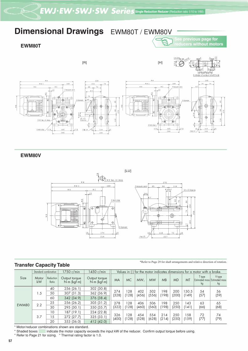
57
一段減速 (減速比1/10~1/60)Single Reduction Reducer (Reduction ratio 1/10 to 1/60)
Dimensional Drawings EWM80T / EWM80V
EWM80T
EWM80V
Transfer Capacity Table*Refer to Page 29 for shaft arrangements and relative direction of rotation.
Size
Standard combination 1750 r/min 1450 r/min Values in ( ) for the motor indicates dimensions for a motor with a brake.
MotorkW
ReductionRatio
Output torque N·m (kgf·m)
Output torque N·m (kgf·m) MA MC MW1 MW MB MD MT
T typeEstimated mass
kg
V typeEstimated mass
kg
EWM80
1.540 256 (26.1) 302 (30.8)
274(328)
128(128)
402(456)
502(556)
198(198)
200(200)
150.5(149)
54(57)
56(59)50 307 (31.3) 362 (36.9)
60 342 (34.9) 376 (38.4)
2.225 256 (26.2) 305 (31.2) 278
(322)128(128)
406(460)
506(560)
198(198)
250(250)
143(141)
63(66)
65(68)30 295 (30.1) 350 (35.7)
3.710 187 (19.1) 224 (22.8)
326(400)
128(128)
454(528)
554(628)
214(214)
250(250)
158(159)
72(77)
74(79)15 272 (27.7) 325 (33.1)
20 353 (36.0) 412 (42.0)* Motor/reducer combinations shown are standard.* Shaded boxes indicate the motor capacity exceeds the input kW of the reducer. Confi rm output torque before using.* Refer to Page 21 for sizing. * Thermal rating factor is 1.0.
165 17.517.5200
100
1515 114144
74 74
148
オイルゲージOil gauge
ドレンプラグ
プレッシャベントPressure vent
13
MC
MW1
MW
MB
MA
MD
MT
8580
110
275
17φ70
4-14キリ
3
5048502.2
3
2.2 88
φ70
14Js9
53.8 φ5
0H8
φ51
φ70 30°φ53 30°
φ53
出力軸穴部詳細Details of output shaft hole
4-14キリ4-φ14
10×8キー10 x 8 keyway
154
228
74
7480
75
60
144
11415 15
17
8580
110
275
φ38h7
MT
2-M8タップ 深さ162-M8 tap, 16 deep
オイルゲージOil gauge
ドレンプラグDrain plug
プレッシャベントPressure vent
200
16517.5 17.5
20
13
MD
MC
100
MA
MB
MW1
MW
[R] [H]
4-φ14
Drain plug
4-15キリ4-φ15
10×8キー10 x 8 keyway
プレッシャベントPressure ventφ38h7
11818 73 18
227
85 80 110
275
104
154
25874
8017
(38)
60 75
MT
オイルゲージOil gauge
ドレンプラグDrain plug
17418 18
210
MC
100
13
MD
MA
MB
MW1
MW
20
2-M8タップ深さ162-M8 tap, 16 deep
[LU]
See previous page for reducers without motors
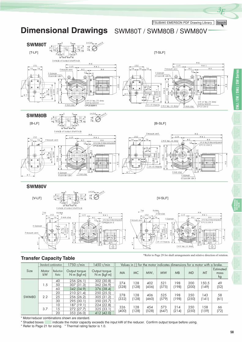
58
3Eつばき PDF図面ライブラリーTSUBAKI EMERSON PDF Drawing Library Search
EWJ
/ EW
/ SW
J / S
W S
erie
s
Dimensional Drawings SWM80T / SWM80B / SWM80V
SWM80T
SWM80B
SWM80V
Transfer Capacity Table*Refer to Page 29 for shaft arrangements and relative direction of rotation.
Size
Standard combination 1750 r/min 1450 r/min Values in ( ) for the motor indicates dimensions for a motor with a brake.
MotorkW
ReductionRatio
Output torque N·m (kgf·m)
Output torque N·m (kgf·m) MA MC MW1 MW MB MD MT
Estimatedmasskg
SWM80
1.540 256 (26.1) 302 (30.8)
274(328)
128(128)
402(456)
521(575)
198(198)
200(200)
150.5(149)
49(52)50 307 (31.3) 362 (36.9)
60 342 (34.9) 376 (38.4)
2.220 210 (21.4) 250 (25.5)
278(332)
128(128)
406(460)
525(579)
198(198)
250(250)
143(141)
58(61)25 256 (26.2) 305 (31.2)
30 295 (30.1) 350 (35.7)
3.710 187 (19.1) 224 (22.8)
326(400)
128(128)
454(528)
573(647)
214(214)
250(250)
158(159)
66(72)15 272 (27.7) 325 (33.1)
20 353 (36.0) 412 (42.0)* Motor/reducer combinations shown are standard.* Shaded boxes indicate the motor capacity exceeds the input kW of the reducer. Confi rm output torque before using.* Refer to Page 21 for sizing. * Thermal rating factor is 1.0.
出力軸穴部詳細Details of output shaft hole
30°
φ53
φ70 φ51
8 82.2
3
50 48 50
3
φ5330°
φ70
φ50H8
53.8
14Js9
2.2 [T-SLF][T-LF]
6
φ704
φ160H7
φ200
73 78151
プレッシャベントPressure vent
6-M10 タップ深さ20 等配(PCD180)ドレンフラグDrain plug
6-M10 tap, 20 deep evenly spaced
オイルゲージ(反対側)
Oil gauge(Opposite side) M
D
104.5
8072
256.5
13MC
119
MB
MAMW1
MW
MT
MD
104.5
8072
256.5
13MC
1197874
6-M10 タップ深さ20 等配(PCD180)
6-M10 tap, 20 deep evenly spaced
ドレンプラグDrain plug2-M8 タ ップ深さ162-M8 tap, 16 deep
プレッシャベントPressure vent
オイルゲージ(反対面)Oil gauge(Opposite side)
76
20
MB
MAMW1
MW152
6
10×8 キー10 x 8 keyway
6075
φ38h7 φ200
φ160H7
4MT
出力軸穴部詳細Details of output shaft hole
30°
φ53
φ70 φ51
8 82.2
3
50 48 50
3
φ5330°
φ70
φ50H8
53.8
14Js9
2.2 [B-SLF][B-LF]
6
φ70
4
φ160H7
φ200
プレッシャベントPressure vent7874
MT
152
ドレンプラグDrain plugオイルゲージ(反対側)
Oil gauge(Opposite side)
104.5
8072
256.5
6-M10 タップ深さ20 等配(PCD180)6-M10 tap, 20 deep evenly spaced
119
13
MD
MC
MB
MAMW1
MW119
787413
MD
104.5
8072
256.5
MC
10×8 キー10 x 8 keyway
6-M10 タ ップ深さ20 等配(PCD180)6-M10 tap, 20 deep evenly spaced
オイルゲージ(反対面)Oil gauge(Opposite side)
ドレンプラグDrain plug
プレッシャベントPressure vent
6075
φ38h7
2-M8 タ ップ深さ162-M8 tap, 16 deep
20
φ200
φ160H7
46
76
MT
MAMW1
MW
MB
152
[V-SLF][V-LF]
出力軸穴部詳細Details of output shaft hole
30°
φ53
φ70 φ51
8 82.2
3
50 48 50
3
φ5330°
φ70
φ50H8
53.8
14Js9
2.2
6-M10 タップ深さ20 等配(PCD180)6-M10 tap, 20 deep evenly spaced
119
13
MD
104.5
8072
256.5
MT
MC MA
MB
MW1MW
ドレンプラグDrain plug
オイルゲージOil gauge
プレッシャベントPressure vent
天Top 地Bottom
7874152
6
φ70
4
φ160H7
φ200
MT
天Top 地Bottom
1197874
13
MD
104.5
8072
256.5
MC
6
プレッシャベントPressure vent
ドレンプラグDrain plug
6-M10 タ ップ深さ20 等配(PCD180)6-M10 tap, 20 deep evenly spacedオイルゲージOil gauge
20
2-M8 タ ップ深さ162-M8 tap, 16 deep
φ38h7
7560
10×8 キー10 x 8 keyway
φ200
φ160H7
4
76
MB
MAMW1
MW152
Single
Red
uctio
n Ge
ar Re
duce
rsSp
ecifi c
ation
s
Single
Red
uctio
n Ge
ar Re
duce
rsSiz
e 42
Single
Red
uctio
n Ge
ar Re
duce
rsSiz
e 50
Single
Red
uctio
n Ge
ar Re
duce
rsSiz
e 63
Single
Red
uctio
n Ge
ar Re
duce
rsSiz
e 70
Sing
le R
educ
tion
Gear
Red
ucer
sSi
ze80
Sing
le R
educ
tion
Gear
Red
ucer
sSi
ze10
0
Sing
le R
educ
tion
Gear
Red
ucer
sSi
ze12
5
Sing
le R
educ
tion
Gear
Red
ucer
sSi
ze15
0
Sing
le R
educ
tion
Gear
Red
ucer
sSi
ze17
5
Sing
le R
educ
tion
Gear
Red
ucer
sSi
ze20
0
Single
Red
uctio
n Ge
ar Re
duce
rsSiz
e 25/3
5
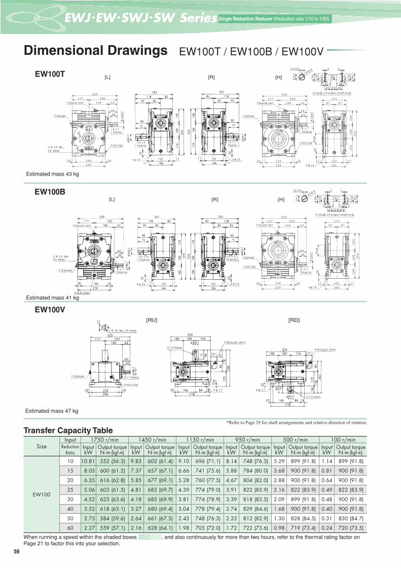
59
一段減速 (減速比1/10~1/60)Single Reduction Reducer (Reduction ratio 1/10 to 1/60)
Dimensional Drawings EW100T / EW100B / EW100V
EW100T
Estimated mass 43 kg
EW100B
Estimated mass 41 kg
EW100V
Estimated mass 47 kg
SizeInput 1750 r/min 1450 r/min 1150 r/min 950 r/min 500 r/min 100 r/min
ReductionRatio
Input Output torque Input Output torque Input Output torque Input Output torque Input Output torque Input Output torquekW N·m (kgf·m) kW N·m (kgf·m) kW N·m (kgf·m) kW N·m (kgf·m) kW N·m (kgf·m) kW N·m (kgf·m)
EW100
10 10.81 552 (56.3) 9.83 602 (61.4) 9.10 696 (71.1) 8.14 748 (76.3) 5.29 899 (91.8) 1.14 899 (91.8)
15 8.05 600 (61.2) 7.37 657 (67.1) 6.66 741 (75.6) 5.88 784 (80.0) 3.68 900 (91.8) 0.81 900 (91.8)
20 6.35 616 (62.8) 5.85 677 (69.1) 5.28 760 (77.5) 4.67 804 (82.0) 2.88 900 (91.8) 0.64 900 (91.8)
25 5.06 603 (61.5) 4.81 683 (69.7) 4.39 774 (79.0) 3.91 822 (83.9) 2.16 822 (83.9) 0.49 822 (83.9)
30 4.52 623 (63.6) 4.18 685 (69.9) 3.81 774 (78.9) 3.39 818 (83.5) 2.09 899 (91.8) 0.48 900 (91.8)
40 3.52 618 (63.1) 3.27 680 (69.4) 3.04 778 (79.4) 2.74 829 (84.6) 1.68 900 (91.8) 0.40 900 (91.8)
50 2.75 584 (59.6) 2.64 661 (67.5) 2.43 748 (76.3) 2.23 812 (82.9) 1.30 828 (84.5) 0.31 830 (84.7)
60 2.27 559 (57.1) 2.16 628 (64.1) 1.98 705 (72.0) 1.72 722 (73.6) 0.98 719 (73.4) 0.24 720 (73.5)
When running a speed within the shaded boxes , and also continuously for more than two hours, refer to the thermal rating factor on Page 21 to factor this into your selection.
Transfer Capacity Table*Refer to Page 29 for shaft arrangements and relative direction of rotation.
19420 20234
140 63203117
320
5060
ドレンプラグDrain plug
オイルゲージOil gauge
8×7キー8 x 7keyway
プレッシャベントPressure vent
φ28h7
13217 17166
20
100
100
124
324
87 87174
4-16キリ4-φ16
φ80
8×7キー8 x 7 keyway
2-M10タップ 深さ202-M10 tap, 20 deep
プレッシャベントPressure vent
ドレンプラグDrain plug
4-φ16 4-φ16
14 x 9 keyway
14 x 9 keyway
19420 20234
140 63203117
320
5060
22
オイルゲージOil gauge
φ28h7
出力軸穴部詳細Details of output shaft hole
30°
φ5859.3
60
3
2.2
30°
φ55H8
φ58
φ80
3
8 2.2 860
φ80φ56
54
16Js9
[L] [R] [H]
19420 20234
140 63203117
320
5060
オイルゲージOil gauge
8×7キー8 x 7 keyway
プレッシャベントPressure vent
ドレンプラグDrain plug
φ28h7
13217 17166
20 100
100
124
324
87 87174
4-16キリ4-φ16
φ80
出力軸穴部詳細Details of output shaft hole
2-M10 tap, 20 deep
Pressure vent
Oil gauge
14 x 9keyway
4-φ16
14 x 9keyway
4-φ16
Drain plug
8 x 7 keyway
30°
φ5859.3
60
3
2.2
30°
φ55H8
φ58
φ80
3
8 2.2 860
φ80φ56
54
16Js9
[L] [R] [H]
2-M10タップ 深さ202-M10 tap, 20 deep
14 x 9 keywayPressure vent
Pressure vent
4-φ17 4-φ17
14 x 9 keyway
Oil gauge
Drain plug
8 x 7 keyway
22 [RU] [RD]
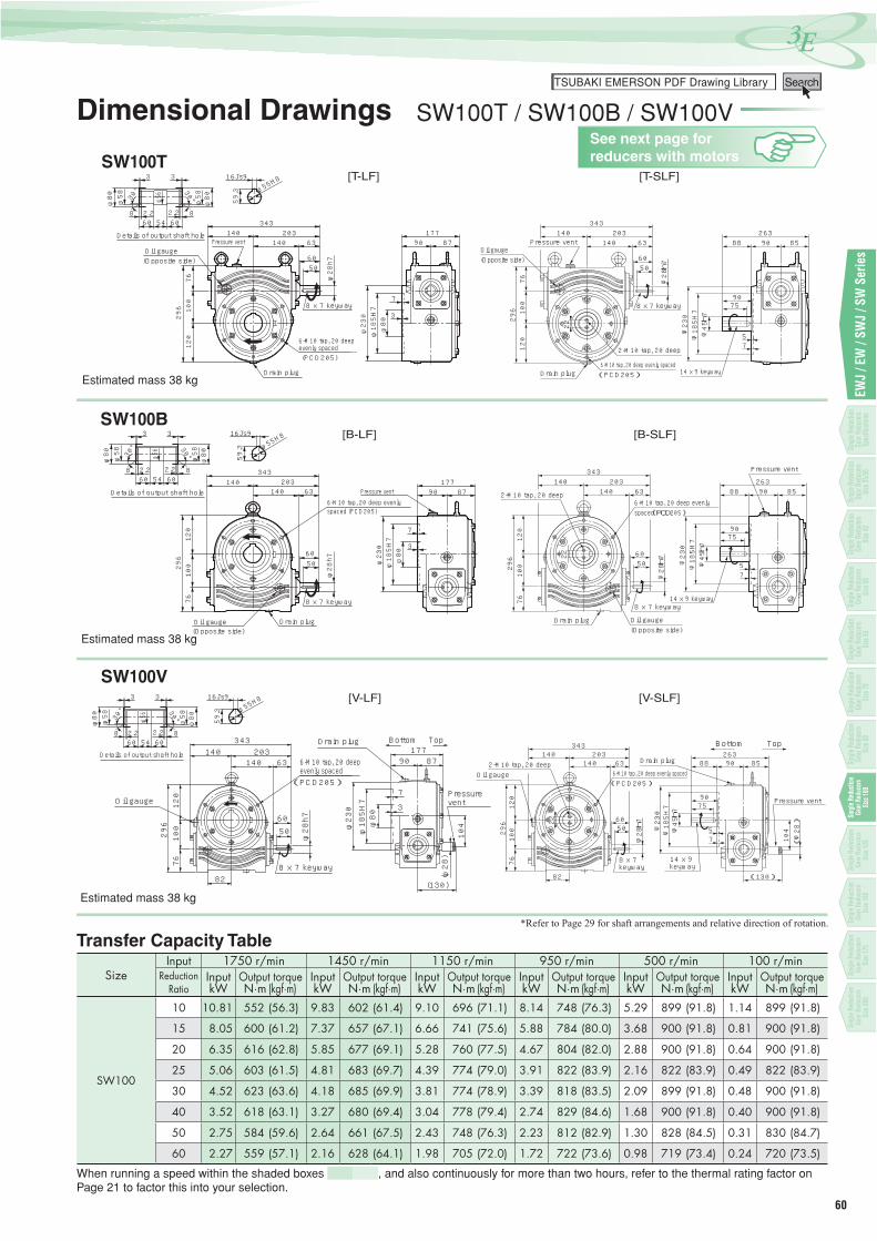
60
3Eつばき PDF図面ライブラリーTSUBAKI EMERSON PDF Drawing Library Search
EWJ
/ EW
/ SW
J / S
W S
erie
s
Dimensional Drawings SW100T / SW100B / SW100V
SW100T
Estimated mass 38 kg
SW100B
Estimated mass 38 kg
SW100V
Estimated mass 38 kg
SizeInput 1750 r/min 1450 r/min 1150 r/min 950 r/min 500 r/min 100 r/min
ReductionRatio
Input Output torque Input Output torque Input Output torque Input Output torque Input Output torque Input Output torquekW N·m (kgf·m) kW N·m (kgf·m) kW N·m (kgf·m) kW N·m (kgf·m) kW N·m (kgf·m) kW N·m (kgf·m)
SW100
10 10.81 552 (56.3) 9.83 602 (61.4) 9.10 696 (71.1) 8.14 748 (76.3) 5.29 899 (91.8) 1.14 899 (91.8)
15 8.05 600 (61.2) 7.37 657 (67.1) 6.66 741 (75.6) 5.88 784 (80.0) 3.68 900 (91.8) 0.81 900 (91.8)
20 6.35 616 (62.8) 5.85 677 (69.1) 5.28 760 (77.5) 4.67 804 (82.0) 2.88 900 (91.8) 0.64 900 (91.8)
25 5.06 603 (61.5) 4.81 683 (69.7) 4.39 774 (79.0) 3.91 822 (83.9) 2.16 822 (83.9) 0.49 822 (83.9)
30 4.52 623 (63.6) 4.18 685 (69.9) 3.81 774 (78.9) 3.39 818 (83.5) 2.09 899 (91.8) 0.48 900 (91.8)
40 3.52 618 (63.1) 3.27 680 (69.4) 3.04 778 (79.4) 2.74 829 (84.6) 1.68 900 (91.8) 0.40 900 (91.8)
50 2.75 584 (59.6) 2.64 661 (67.5) 2.43 748 (76.3) 2.23 812 (82.9) 1.30 828 (84.5) 0.31 830 (84.7)
60 2.27 559 (57.1) 2.16 628 (64.1) 1.98 705 (72.0) 1.72 722 (73.6) 0.98 719 (73.4) 0.24 720 (73.5)
When running a speed within the shaded boxes , and also continuously for more than two hours, refer to the thermal rating factor on Page 21 to factor this into your selection.
Transfer Capacity Table*Refer to Page 29 for shaft arrangements and relative direction of rotation.
[T-SLF][T-LF]
プレッシャベントPressure vent
8×7キ-8 x 7 keyway
6-M10タップ 深さ20 等配(PCD205)
ドレンプラグ
(反対側)(Opposite side)オイルゲ-ジOil gauge
φ230
φ185H7
φ80
7
3
φ28h760
50
120
100
76296
63140203140
343
90 87177出力軸穴部詳細Details of output shaft hole
30°
φ58 59.3
60
3
2.2
30°
φ55H8
φ58
φ80
3
8 2.2 860
φ80φ56
54
16Js9
7
φ28h760
50
120
100
76296
63140203140
343
90
2-M10タ ップ 深さ20 2-M10 tap, 20 deep
14×9キー14 x 9 keyway
9075
φ45h7
22
φ185H7
φ230
8588263
ドレンプラグDrain plug6-M10タップ 深さ20 等配(PCD205)6-M10 tap, 20 deep evenly spaced(PCD205)
5
オイルゲージ(反対側)Oil gauge(Opposite side)
プレッシャベントPressure vent
8×7キー8 x 7 keyway
6-M10 tap, 20 deep evenly spaced
Drain plug
[B-SLF][B-LF]
Pressure vent
8×7キ-8 x 7 keyway
6-M10タップ 深さ20 等配6-M10 tap, 20 deep evenly spaced (PCD205)
ドレンプラグDrain plug(Opposite side)オイルゲ-ジOil gauge
出力軸穴部詳細Details of output shaft hole 90 87177
φ230
φ185H7
φ80
7
3
63140203140
343
φ28h7
6050
120
100
76296
30°
φ58 59.3
60
3
2.2
30°
φ55H8
φ58
φ80
3
8 2.2 860
φ80φ56
54
16Js9
φ230
φ185H7
7
63140203140
343
φ28h760
50
120
100
76296
8526390
22
φ45h7
7590
88
プレッシャベントPressure vent
14 x 9 keyway
2-M10タ ップ 深さ202-M10 tap, 20 deep
オイルゲージ(反対側)Oil gauge(Opposite side)
ドレンプラグDrain plug
6-M10タップ 深さ20 等配(PCD205)6-M10 tap, 20 deep evenly spaced(PCD205)
8×7キー8 x 7 keyway
5
オイルゲージOil gauge
296
76100
120
343140
828×7キー8 x 7 keyway
5060
(PCD205)
地Bottom177
7
3
プレッシャベント
90
(130)
ドレンプラグDrain plug
87
天Top
φ28h7
φ230
(φ28)
104
φ185H7
φ80
140 63203
6-M10タップ 深さ20 等配
出力軸穴部詳細Details of output shaft hole
30°
φ58 59.3
60
3
2.2
30°φ55H8
φ58
φ80
3
8 2.2 860
φ80φ56
54
16Js9
140203140
343
[V-SLF][V-LF]
90
7
63140203140
343
φ28h760
50
120
100
76296
104
(130)
(φ28)
82
5φ230
φ185H7
22
φ45h7 75
90
14×9キー14 x 9 keyway
2-M10タ ップ 深さ20 2-M10 tap, 20 deepオイルゲージOil gauge 6-M10タップ 深さ20 等配
(PCD205)6-M10 tap, 20 deep evenly spaced(PCD205)
8588263
ドレンプラグDrain plug
プレッシャベントPressure vent
8×7キー8 x 7 keyway
天地
6-M10 tap, 20 deep evenly spaced
Pressure vent
Bottom Top
See next page for reducers with motors
Single
Red
uctio
n Ge
ar Re
duce
rsSp
ecifi c
ation
s
Single
Red
uctio
n Ge
ar Re
duce
rsSiz
e 42
Single
Red
uctio
n Ge
ar Re
duce
rsSiz
e 50
Single
Red
uctio
n Ge
ar Re
duce
rsSiz
e 63
Single
Red
uctio
n Ge
ar Re
duce
rsSiz
e 70
Single
Red
uctio
n Ge
ar Re
duce
rsSiz
e 80
Sing
le R
educ
tion
Gear
Red
ucer
sSi
ze10
0
Sing
le R
educ
tion
Gear
Red
ucer
sSi
ze12
5
Sing
le R
educ
tion
Gear
Red
ucer
sSi
ze15
0
Sing
le R
educ
tion
Gear
Red
ucer
sSi
ze17
5
Sing
le R
educ
tion
Gear
Red
ucer
sSi
ze20
0
Single
Red
uctio
n Ge
ar Re
duce
rsSiz
e 25/3
5

61
一段減速 (減速比1/10~1/60)Single Reduction Reducer (Reduction ratio 1/10 to 1/60)
Dimensional Drawings EWM100T / EWM100V
EWM100T
EWM100V
Transfer Capacity Table*Refer to Page 29 for shaft arrangements and relative direction of rotation.
Size
Standard combination 1750 r/min 1450 r/min Values in ( ) for the motor indicates dimensions for a motor with a brake.
MotorkW
ReductionRatio
Output torque N·m (kgf·m)
Output torque N·m (kgf·m) MA MC MW1 MW MB MD MT
T typeEstimated mass
kg
V typeEstimated mass
kg
EWM100
2.240 386 (39.4) 457 (46.7)
278(332)
150(150)
428(482)
545(599)
198(198)
250(250)
143(143)
78(81)
82(85)50 467 (47.6) 552 (56.3)
60 543 (55.4) 628 (64.1)
3.725 440 (44.9) 525 (53.6) 326
(400)150(150)
476(550)
593(667)
214(214)
250(250)
158(159)
86(92)
90(96)30 510 (52.1) 607 (61.9)
5.510 281 (28.6) 337 (34.3)
413(511)
157(157)
570(668)
687(785)
252(252)
300(300)
190(193)
104(120)
108(124)15 410 (41.8) 491 (50.1)
20 533 (54.4) 637 (65.0)* Motor/reducer combinations shown are standard.* Shaded boxes indicate the motor capacity exceeds the input kW of the reducer. Confi rm output torque before using.* Refer to Page 21 for sizing. * Thermal rating factor is 1.0.
[R] [H]
出力軸穴部詳細Details of output shaft hole
30°
φ5859.3
60
3
2.2
30°
φ55H8
φ58
φ80
3
8 2.2 860
φ80φ56
54
16Js9
13217 17
166
20
100
100
124
324
194 2020
234
117
φ80
87 87
174
ドレンプラグDrain plug
オイルゲージOil gauge
プレッシャベントPressure vent
4-16キリ4-φ16
MA
MW1
MW
MB
MC
14
MD MT
4-16キリ4-φ16
14×9キー14 x 9 keyway
13217 17
166
20
φ45h7
75
90
93 85
178 85
263
124
324
100
100
MT
2-M10タップ 深さ202-M10 tap, 20 deep
オイルゲージOil gauge
ドレンプラグDrain plug
プレッシャベントPressure vent
19420 20
234
22
MC
117
MB
MA
MW1
MW
MD
14
[LU]
4-17キリ4-φ17
2-M10タップ 深さ202-M10 tap, 20 deep
14×9キー14 x 9 keyway
プレッシャベントPressure vent
φ45h7
22
146 8420 28
278
2085
93
178
120
298
100 100 124
324
(38)
75 90
MT
オイルゲージOil gauge
ドレンプラグDrain plug
220 2020
260
117
MC
14
MD
MB
MA
MW1
MW
See previous page for reducers without motors

62
3Eつばき PDF図面ライブラリーTSUBAKI EMERSON PDF Drawing Library Search
EWJ
/ EW
/ SW
J / S
W S
erie
s
Dimensional Drawings SWM100T / SWM100B / SWM100V
SWM100T
SWM100B
SWM100V
Transfer Capacity Table*Refer to Page 29 for shaft arrangements and relative direction of rotation.
Size
Standard combination 1750 r/min 1450 r/min Values in ( ) for the motor indicates dimensions for a motor with a brake.
MotorkW
ReductionRatio
Output torque N·m (kgf·m)
Output torque N·m (kgf·m) MA MC MW1 MW MB MD MT
Estimatedmasskg
SWM100
2.240 386 (39.4) 457 (46.7)
278(332)
150(150)
428(482)
568(622)
198(198)
250(250)
143(141)
71(74)50 467 (47.6) 552 (56.3)
60 543 (55.4) 628 (64.1)
3.725 440 (44.9) 525 (53.6) 326
(400)150(150)
476(550)
616(690)
214(214)
250(250)
158(159)
79(85)30 510 (52.1) 607 (61.9)
5.510 281 (28.6) 337 (34.3)
413(511)
157(157)
570(668)
710(808)
252(252)
300(300)
190(193)
92(108)15 410 (41.8) 491 (50.1)
20 533 (54.4) 637 (65.0)* Motor/reducer combinations shown are standard.* Shaded boxes indicate the motor capacity exceeds the input kW of the reducer. Confi rm output torque before using.* Refer to Page 21 for sizing. * Thermal rating factor is 1.0.
59.3
602.2
16Js9
φ58
φ58 φ5
5H8
82.28
φ80
φ80
5460
3 3
φ56
出力軸穴部詳細Details of output shaft hole
30°30°
[B-SLF][B-LF]
120
100
76296
14
MD
140MC90
5
6-M10 タ ップ深さ20 等配(PCD205)6-M10 tap, 20 deep evenly spaced(PCD205)
ドレンプラグDrain plugオイルゲージ(反対面)Oil gauge(Opposite side)
2-M10 タップ深さ202-M10 tap, 20 deep
キー 14×914 x 9 keyway
プレッシャベントPressure vent88
9075
φ 45h7
22
7 φ185H7
φ230
85
MB
MT
MAMW1
MW175
プレッシャベントPressure vent
φ230
φ185H7
φ80
73
9087177
6-M10 タップ深さ20 等配(PCD205)6-M10 tap, 20 deep evenly spaced(PCD205)
ドレンプラグDrain plugオイルゲージ(反対側)
Oil gauge(Opposite side)
120
100
76296
14
140MC MA
MB
MD
MW1MW
MT
59.3
602.2
16Js9
φ58
φ58 φ5
5H8
82.28
φ80
φ80
5460
3 3
φ56
出力軸穴部詳細Details of output shaft hole
30°30°
[T-SLF][T-LF]
120
10076
296
MD
MC140
14プレッシャベントPressure vent
オイルゲージ(反対面)Oil gauge(Opposite side)
6-M10 タ ップ深さ20 等配(PCD205)
6-M10 tap, 20 deep evenly spaced(PCD205)
ドレンプラグDrain plug
22
2-M10 タップ深さ202-M10 tap, 20 deep
MB
MAMW1
MW
90
5
88
φ230
φ185H7
φ 45h7
7590
キー14×914 x 9 keyway7
85
MT
175
MT
φ230
φ185H7
φ80
7
3
9087177
6-M10 タップ深さ20 等配(PCD205)6-M10 tap, 20 deep evenly spaced(PCD205)ドレンプラグDrain plug
オイルゲージ(反対側)
Oil gauge(Opposite side)
プレッシャベントPressure vent
120
10076
296
MC140
14MA
MB
MD
MW1MW
[V-SLF][V-LF] 59.3
602.2
16Js9
φ58
φ58 φ55
H8
82.28
φ80
φ80
5460
3 3
φ56
出力軸穴部詳細Details of output shaft hole
30°30°
6-M10 タップ深さ20 等配(PCD205)6-M10 tap, 20 deep evenly spaced(PCD205)
120
100
76296
14
140MC
MD
MA
MB
MW1MW
ドレンプラグDrain plug
オイルゲージOil gauge
プレッシャベントPressure vent
天 地
9087177
φ230
φ185H7
φ80
37
MT
120
100
76296
14
MD
140MC
6-M10 タ ップ深さ20 等配(PCD205)6-M10 tap, 20 deep evenly spaced(PCD205)
オイルゲージOil gauge2-M10 タップ深さ202-M10 tap, 20 deep
22
MAMW1
MW
MB
天 地
90プレッシャベントPressure vent
ドレンプラグDrain plug88
キー 14×914 x 9 keyway
9075
φ 45h7 φ185H7
φ230
5
7
85
MT
175
Top BottomTop Bottom
Single
Red
uctio
n Ge
ar Re
duce
rsSp
ecifi c
ation
s
Single
Red
uctio
n Ge
ar Re
duce
rsSiz
e 42
Single
Red
uctio
n Ge
ar Re
duce
rsSiz
e 50
Single
Red
uctio
n Ge
ar Re
duce
rsSiz
e 63
Single
Red
uctio
n Ge
ar Re
duce
rsSiz
e 70
Single
Red
uctio
n Ge
ar Re
duce
rsSiz
e 80
Sing
le R
educ
tion
Gear
Red
ucer
sSi
ze10
0
Sing
le R
educ
tion
Gear
Red
ucer
sSi
ze12
5
Sing
le R
educ
tion
Gear
Red
ucer
sSi
ze15
0
Sing
le R
educ
tion
Gear
Red
ucer
sSi
ze17
5
Sing
le R
educ
tion
Gear
Red
ucer
sSi
ze20
0
Single
Red
uctio
n Ge
ar Re
duce
rsSiz
e 25/3
5
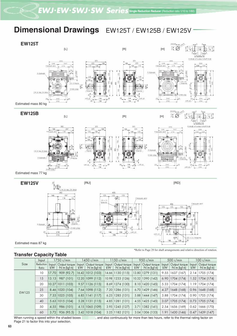
63
一段減速 (減速比1/10~1/60)Single Reduction Reducer (Reduction ratio 1/10 to 1/60)
Dimensional Drawings EW125T / EW125B / EW125V
EW125T
Estimated mass 80 kg
EW125B
Estimated mass 77 kg
EW125V
Estimated mass 87 kg
SizeInput 1750 r/min 1450 r/min 1150 r/min 950 r/min 500 r/min 100 r/min
ReductionRatio
Input Output torque Input Output torque Input Output torque Input Output torque Input Output torque Input Output torquekW N·m (kgf·m) kW N·m (kgf·m) kW N·m (kgf·m) kW N·m (kgf·m) kW N·m (kgf·m) kW N·m (kgf·m)
EW125
10 17.70 909 (92.7) 16.42 1012 (103) 14.66 1130 (115) 13.80 1279 (131) 9.55 1637 (167) 2.14 1705 (174)
15 13.13 987 (101) 12.20 1099 (112) 10.98 1233 (126) 10.32 1390 (142) 6.90 1704 (174) 1.52 1704 (174)
20 10.27 1011 (103) 9.57 1126 (115) 8.69 1274 (130) 8.10 1420 (145) 5.33 1704 (174) 1.19 1704 (174)
25 8.46 1020 (104) 7.64 1098 (112) 7.20 1286 (131) 6.70 1429 (146) 4.27 1648 (168) 0.96 1648 (168)
30 7.33 1025 (105) 6.85 1141 (117) 6.23 1285 (131) 5.88 1444 (147) 3.88 1704 (174) 0.90 1705 (174)
40 5.63 1015 (104) 5.28 1131 (115) 4.85 1281 (131) 4.55 1425 (145) 3.07 1705 (174) 0.73 1705 (174)
50 4.55 986 (101) 4.15 1065 (109) 3.95 1245 (127) 3.71 1382 (141) 2.54 1656 (169) 0.62 1666 (170)
60 3.72 936 (95.5) 3.42 1018 (104) 3.25 1182 (121) 3.04 1306 (133) 1.91 1430 (146) 0.47 1439 (147)
When running a speed within the shaded boxes , and also continuously for more than two hours, refer to the thermal rating factor on Page 21 to factor this into your selection.
Transfer Capacity Table*Refer to Page 29 for shaft arrangements and relative direction of rotation.
[L] [R] [H]
10×8キー10 x 8 keyway
2-M10タップ 深さ202-M10 tap, 20 deep
プレッシャベントPressure vent
ドレンプラグDrain plug 18 x 11 keyway
4-φ18
24773174
146393
5570
24225 25292
36
φ35h7
Oil gauge
100
125
125
155
405
154194
20 20
25
100100200
φ105
4-18キリ4-φ18
24773174
146393
5570
24225 25292
φ35h7
オイルゲージOil gauge
4-φ18
18 x 11 keyway
ドレンプラグDrain plug
10×8キー10 x 8 keyway
プレッシャベントPressure vent
20Js9
74.9 φ7
0H8
φ73
φ73
φ105
φ105
706070
30°
2.72.7 88
33
φ71
出力軸穴部詳細Details of output shaft hole
30°
[L] [R] [H]
100
125
125
155
405
154194
20 20
25
100200
φ105
4-18キリ4-φ18
24773174
146393
5570
24225 25292
φ35h7
オイルゲージOil gauge
ドレンプラグ
4-φ18
10×8キー10 x 8 keyway
プレッシャベントPressure vent
20Js9
74.9 φ7
0H8
φ73
φ73
φ105
φ105
706070
30°
2.72.7 88
33
φ71
出力軸穴部詳細Details of output shaft hole
30°
Pressure vent
2-M10 tap, 20 deep
Oil gauge
18 x 11 keyway
18 x 11 keyway
Drain plug
10 x 8 keyway
4-φ18
Drain plug
[RU] [RD]
2-M10タップ 深さ202-M10 tap, 20 deep
Oil gauge
Drain plug
Pressure vent
Pressure vent
4-φ194-φ19
18 x 11 keyway
18 x 11 keyway
10 x 8 keyway
36

64
3Eつばき PDF図面ライブラリーTSUBAKI EMERSON PDF Drawing Library Search
EWJ
/ EW
/ SW
J / S
W S
erie
s
Dimensional Drawings SW125T / SW125B / SW125V
SW125T
Estimated mass 72 kg
SW125B
Estimated mass 72 kg
SW125V
Estimated mass 72 kg
SizeInput 1750 r/min 1450 r/min 1150 r/min 950 r/min 500 r/min 100 r/min
ReductionRatio
Input Output torque Input Output torque Input Output torque Input Output torque Input Output torque Input Output torquekW N·m (kgf·m) kW N·m (kgf·m) kW N·m (kgf·m) kW N·m (kgf·m) kW N·m (kgf·m) kW N·m (kgf·m)
SW125
10 17.70 909 (92.7) 16.42 1012 (103) 14.66 1130 (115) 13.80 1279 (131) 9.55 1637 (167) 2.14 1705 (174)
15 13.13 987 (101) 12.20 1099 (112) 10.98 1233 (126) 10.32 1390 (142) 6.90 1704 (174) 1.52 1704 (174)
20 10.27 1011 (103) 9.57 1126 (115) 8.69 1274 (130) 8.10 1420 (145) 5.33 1704 (174) 1.19 1704 (174)
25 8.46 1020 (104) 7.64 1098 (112) 7.20 1286 (131) 6.70 1429 (146) 4.27 1648 (168) 0.96 1648 (168)
30 7.33 1025 (105) 6.85 1141 (117) 6.23 1285 (131) 5.88 1444 (147) 3.88 1704 (174) 0.90 1705 (174)
40 5.63 1015 (104) 5.28 1131 (115) 4.85 1281 (131) 4.55 1425 (145) 3.07 1705 (174) 0.73 1705 (174)
50 4.55 986 (101) 4.15 1065 (109) 3.95 1245 (127) 3.71 1382 (141) 2.54 1656 (169) 0.62 1666 (170)
60 3.72 936 (95.5) 3.42 1018 (104) 3.25 1182 (121) 3.04 1306 (133) 1.91 1430 (146) 0.47 1439 (147)
When running a speed within the shaded boxes , and also continuously for more than two hours, refer to the thermal rating factor on Page 21 to factor this into your selection.
Transfer Capacity Table*Refer to Page 29 for shaft arrangements and relative direction of rotation.
φ285
φ230H7
φ105
6
10
110 100210
プレッシャベントPressure vent
6-M12タップ 深さ25 等配6-M12 tap, 25 deep evenly spaced(PCD255)
ドレンプラグDrain plug
(反対側)オイルゲ-ジOil gauge(Opposite side)
10×8キ-10 x 8 keyway
5570
φ35h7
148
125
87360
174 73247174
421
20Js9
74.9 φ7
0H8
φ73
φ73
φ105
φ105
706070
30°
2.72.7 88
33
φ71
出力軸穴部詳細Details of output shaft hole
30°
5570
φ35h7
148
125
87360
6
110 100174 73247174
421
2-M10タップ 深さ202-M10 tap, 20 deep 18×11キー18 x 11 keyway
10
120100
φ60h7
36
オイルゲージ(反対側)Oil gauge
(Opposite side)
ドレンプラグDrain plug
10×8キー10 x 8 keyway
6-M12タ ップ 深さ25 等配(PCD255)
6-M12 tap, 25 deep evenly spaced(PCD255)
プレッシャベントPressure vent 115325
φ285
φ230H7
[T-SLF][T-LF]
プレッシャベントPressure vent
6-M12 tap, 25 deep evenly spaced
110 100210
φ285
φ230H7
φ105
6
10
(PCD255)
10×8キ-10 x 8 keyway
5570
φ35h7
174 73247174
421
Drain plug(反対側)(Opposite side)オイルゲ-ジOil gauge
148
125
87360
20Js9
74.9 φ7
0H8
φ73
φ73
φ105
φ105
706070
30°
2.72.7 88
33
φ71
出力軸穴部詳細Details of output shaft hole
30°
5570
φ35h7
174 73247174
421
148
125
87360
110 100プレッシャベントPressure vent6-M12タ ップ 深さ25 等配(PCD255)6-M12 tap, 25 deep evenly spaced(PCD255)
10×8キー10 x 8 keyway
ドレンプラグDrain plug オイルゲージ(反対側)Oil gauge(Opposite side)
36
φ60h7
100120
115325
610
18×11キー18 x 11 keyway
2-M10タップ 深さ202-M10 tap, 20 deep
φ285
φ230H7
[B-SLF][B-LF]
オイルゲージOil gauge
10×8キー10 x 8 keyway
5570
φ35h7
174 73247174
421
148
125
87360
105
6-M12タップ 深さ25 等配6-M12 tap, 25 deep evenly spaced(PCD255)
プレッシャベント
ドレンプラグDrain plug地 天Bottom Top
110 100210
φ285
φ230H7
φ105
610
(φ35)
(145)
125
174 73247174
421
20Js9
74.9 φ7
0H8
φ73
φ73
φ105
φ105
706070
30°
2.72.7 88
33
φ71
出力軸穴部詳細Details of output shaft hole
30°
5570
φ35h7
174 73247174
421
148
125
87360
110 100
(φ35)
(145)
125
105
2-M10タップ 深さ20 2-M10 tap, 20 deep
18×11キー18 x 11 keyway
10
120100
φ60h7
36
オイルゲージ(反対側)Oil gauge ドレンプラグ
10×8キー10 x 8 keyway
6-M12タ ップ 深さ25 等配(PCD255)6-M12 tap, 25 deep evenly spaced(PCD255)
ドレンプラグDrain plug
プレッシャベントPressure vent
6
115325
φ285
φ230H7
天地
[V-SLF][V-LF]
Pressure vent
Bottom Top
See next page for reducers with motors
Single
Red
uctio
n Ge
ar Re
duce
rsSp
ecifi c
ation
s
Single
Red
uctio
n Ge
ar Re
duce
rsSiz
e 42
Single
Red
uctio
n Ge
ar Re
duce
rsSiz
e 50
Single
Red
uctio
n Ge
ar Re
duce
rsSiz
e 63
Single
Red
uctio
n Ge
ar Re
duce
rsSiz
e 70
Single
Red
uctio
n Ge
ar Re
duce
rsSiz
e 80
Single
Red
uctio
n Ge
ar Re
duce
rsSiz
e 100
Sing
le R
educ
tion
Gear
Red
ucer
sSi
ze12
5
Sing
le R
educ
tion
Gear
Red
ucer
sSi
ze15
0
Sing
le R
educ
tion
Gear
Red
ucer
sSi
ze17
5
Sing
le R
educ
tion
Gear
Red
ucer
sSi
ze20
0
Single
Red
uctio
n Ge
ar Re
duce
rsSiz
e 25/3
5

65
一段減速 (減速比1/10~1/60)Single Reduction Reducer (Reduction ratio 1/10 to 1/60)
Dimensional Drawings EWM125T / EWM125V
EWM125T
EWM125V
Transfer Capacity Table*Refer to Page 29 for shaft arrangements and relative direction of rotation.
Size
Standard combination 1750 r/min 1450 r/min Values in ( ) for the motor indicates dimensions for a motor with a brake.
MotorkW
ReductionRatio
Output torque N·m (kgf·m)
Output torque N·m (kgf·m) MA MC MW1 MW MB MD MT
T typeEstimated mass
kg
V typeEstimated mass
kg
EWM125
3.7
40 667 (68.0) 792 ( 80.8)326(400)
185(185)
511(585)
657(731)
214(214)
250(250)
158(159)
123(129)
130(136)50 802 (81.8) 949 ( 96.8)
60 931 (95.0) 1017 (104 )
5.525 662 (67.6) 791 ( 80.7) 413
(511)185(185)
598(696)
744(842)
252(252)
300(300)
190(193)
141(157)
148(164)30 770 (78.5) 916 ( 93.5)
* Motor/reducer combinations shown are standard.* Shaded boxes indicate the motor capacity exceeds the input kW of the reducer. Confi rm output torque before using.* Refer to Page 21 for sizing. * Thermal rating factor is 1.0.
[LU]
ドレンプラグ
オイルゲージOil gauge
Drain plug
27022 22
314
146
MC
14
MD
MA
MB
MW1
MW
4-19キリ4-φ19
プレッシャベントφ60h7
22 186 104 34
346
25
225
145
370
100
125
120
100
125 125 155
405
(44)
MT
18×11キー18 x 11 keyway
2-M10タップ 深さ202-M10 tap, 20 deep
Pressure vent
36
[R] [H] 20Js9
74.9 φ7
0H8
φ73
φ73
φ105
φ105
706070
30°
2.72.7 88
33
φ71
出力軸穴部詳細Details of output shaft hole
30°
125
125
155
405
154
194
20 20
25
100100
200
φ105
オイルゲージ
4-φ18
MTプレッシャベントPressure vent
Oil gauge
ドレンプラグDrain plug 24225 25
292
146
MC
14
MD
MB
MA
MW1
MW
4-18キリ4-φ18
18×11キー18 x 11 keyway
100
120
225
100125
100325
φ60h7
125
125
155
405
154
194
20 20
25
MT
2-M10タップ 深さ202-M10 tap, 20 deep
オイルゲージOil gauge
プレッシャベントPressure vent
ドレンプラグDrain plug 24225 25
292
36
146
MC
14
MD
MB
MA
MW1
MW
See previous page for reducers without motors

66
3Eつばき PDF図面ライブラリーTSUBAKI EMERSON PDF Drawing Library Search
EWJ
/ EW
/ SW
J / S
W S
erie
s
Size
Standard combination 1750 r/min 1450 r/min Values in ( ) for the motor indicates dimensions for a motor with a brake.
MotorkW
ReductionRatio
Output torque N·m (kgf·m)
Output torque N·m (kgf·m) MA MC MW1 MW MB MD MT
Estimatedmasskg
SWM125
3.7
40 667 (68.0) 792 (80.8)326(400)
185(185)
511(585)
685(759)
214(214)
250(250)
158(159)
112(118)50 802 (81.8) 949 (96.8)
60 931 (95.0) 1017 (104)
5.525 662 (67.6) 791 (80.7) 413
(511)185(185)
598(696)
772(870)
252(252)
300(300)
190(193)
126(142)30 770 (78.5) 916 (93.5)
* Motor/reducer combinations shown are standard.* Shaded boxes indicate the motor capacity exceeds the input kW of the reducer. Confi rm output torque before using.* Refer to Page 21 for sizing. * Thermal rating factor is 1.0.
Dimensional Drawings SWM125T / SWM125B / SWM125V
SWM125T
SWM125B
SWM125V
Transfer Capacity Table*Refer to Page 29 for shaft arrangements and relative direction of rotation.
20Js9
74.9 φ7
0H8
φ73
φ73
φ105
φ105
706070
30°
2.72.7 88
33
φ71
出力軸穴部詳細
30°
[T-SLF][T-LF]
MT
φ285
φ230H7
φ105
6
10
100 110210
プレッシャベント
6-M12 タップ深さ25 等配(PCD255)ドレンプラグ
オイルゲージ(反対側)
148
125
360
87
MC174
14MA
MB
MD
MW1MW
2-M10 タップ深さ20
100 110 115
φ 60h7
100120
10
キー 18×11
6
φ285
φ230H7
MT
210
148
125
360
MD
87
MC174
14プレッシャベント
6-M12 タップ深さ25 等配(PCD255)ドレンプラグ
オイルゲージ(反対面)
36
MWMW1
MA
MB
Details of output shaft hole
Pressure ventOil gauge(Opposite side)
Drain plug
6-M12 tap, 25 deep evenly spaced
Oil gauge(Opposite side)
Pressure vent
18 x 11 keyway 2-M10 tap, 20 deep Drain plug
6-M12 tap, 25 deep evenly spaced
20Js9
74.9 φ7
0H8
φ73
φ73
φ105
φ105
706070
30°
2.72.7 88
33
φ71
出力軸穴部詳細
30°
[B-SLF][B-LF]
プレッシャベント110100210
φ285
φ230H7
φ105
610
6-M12 タップ 深さ25 等配(PCD255)
ドレンプラグオイルゲージ(反対側)
148
125360
14
174MC
87
MD
MA
MB
MW1MW
MT148
125360
110100
87
φ230H7
φ285
2-M10 タップ深さ20
キー 18×11
10
6
115
120100
φ 60h7
プレッシャベント
MT
210
MD
14
174MC
36オイルゲージ(反対面)
ドレンプラグ
6-M12 タップ深さ25 等配(PCD255)
MWMW1
MA
MB
Pressure vent
Details of output shaft hole
Oil gauge(Opposite side) Drain plug
6-M12 tap, 25 deep evenly spaced
Pressure vent
18 x 11 keyway
2-M10 tap, 20 deep
Oil gauge(Opposite side)
Drain plug
6-M12 tap, 25 deep evenly spaced(PCD255)
[V-SLF][V-LF]
20Js9
74.9 φ7
0H8
φ73
φ73
φ105
φ105
706070
30°
2.72.7 88
33
φ71
出力軸穴部詳細
30°
ドレンプラグ
φ285
φ230H7
φ105
地天
110100210
610 14
8125360
87
6-M12 タップ深さ25 等配(PCD255)
MB
MAMW1
MD
14MC
MW174
MT
プレッシャベント
オイルゲージ
MT
MB
MD
14 6-M12 タップ深さ25 等配(PCD255)
MWMW1
MAMC
148
125360
174
87
オイルゲージ
2-M10 タップ深さ20
36
φ 230H7
φ 285
ドレンプラグ
φ 60h7
キー 18×11
115
100120
6
プレッシャベント
10
地天
110100210
Oil gauge
Pressure vent
Top Bottom
Drain plug
Details of output shaft hole
6-M12 tap, 25 deep evenly spaced
Top BottomDrain plug
Oil gauge
Pressure vent
18 x 11 keyway
2-M10 tap, 20 deep
6-M12 tap, 25 deep evenly spaced
Single
Red
uctio
n Ge
ar Re
duce
rsSp
ecifi c
ation
s
Single
Red
uctio
n Ge
ar Re
duce
rsSiz
e 42
Single
Red
uctio
n Ge
ar Re
duce
rsSiz
e 50
Single
Red
uctio
n Ge
ar Re
duce
rsSiz
e 63
Single
Red
uctio
n Ge
ar Re
duce
rsSiz
e 70
Single
Red
uctio
n Ge
ar Re
duce
rsSiz
e 80
Single
Red
uctio
n Ge
ar Re
duce
rsSiz
e 100
Sing
le R
educ
tion
Gear
Red
ucer
sSi
ze12
5
Sing
le R
educ
tion
Gear
Red
ucer
sSi
ze15
0
Sing
le R
educ
tion
Gear
Red
ucer
sSi
ze17
5
Sing
le R
educ
tion
Gear
Red
ucer
sSi
ze20
0
Single
Red
uctio
n Ge
ar Re
duce
rsSiz
e 25/3
5

67
一段減速 (減速比1/10~1/60)Single Reduction Reducer (Reduction ratio 1/10 to 1/60)
Dimensional Drawings EW150T / EW150B / EW150V
EW150T
Estimated mass 122 kg
EW150B
Estimated mass 116 kg
EW150V
Estimated mass 141 kg
SizeInput 1750 r/min 1450 r/min 1150 r/min 950 r/min 500 r/min 100 r/min
ReductionRatio
Input Output torque Input Output torque Input Output torque Input Output torque Input Output torque Input Output torquekW N·m (kgf·m) kW N·m (kgf·m) kW N·m (kgf·m) kW N·m (kgf·m) kW N·m (kgf·m) kW N·m (kgf·m)
EW150
10 26.45 1364 (139) 24.52 1519 (155) 22.36 1734 (177) 20.31 1894 (193) 14.51 2508 (256) 3.29 2646 (270)
15 19.58 1482 (151) 18.19 1650 (168) 16.62 1883 (192) 15.21 2068 (211) 10.41 2600 (265) 2.33 2646 (270)
20 15.33 1519 (155) 14.26 1691 (173) 12.65 1869 (191) 12.05 2134 (218) 8.19 2646 (270) 1.83 2646 (270)
25 12.45 1522 (155) 11.59 1695 (173) 10.48 1906 (195) 9.85 2143 (219) 6.69 2646 (270) 1.50 2646 (270)
30 10.87 1539 (157) 10.15 1713 (175) 9.35 1956 (200) 8.31 2074 (212) 5.42 2421 (247) 1.38 2646 (270)
40 8.36 1525 (156) 7.83 1698 (173) 7.03 1883 (192) 6.74 2144 (219) 4.69 2646 (270) 1.12 2646 (270)
50 6.62 1474 (151) 6.21 1642 (168) 5.68 1849 (189) 5.38 2077 (212) 3.89 2646 (270) 0.93 2646 (270)
60 5.43 1402 (143) 5.11 1561 (159) 4.69 1758 (179) 4.45 1974 (201) 3.31 2563 (262) 0.82 2586 (264)
When running a speed within the shaded boxes , and also continuously for more than two hours, refer to the thermal rating factor on Page 21 to factor this into your selection.
Transfer Capacity Table*Refer to Page 29 for shaft arrangements and relative direction of rotation.
[L] [R] [H]
10×8キー
2-M12タップ 深さ24
プレッシャベント
ドレンプラグ
29229 29350
175 284204 80
7560
459
36
φ38h7
オイルゲージ
30
150
150
180
480
17823 23224
125 125250
φ115
4-22キリ29229 29350
175 284204 80
7560
459
φ38h7
プレッシャベント
ドレンプラグ
10×8キー
オイルゲージ
出力軸穴部詳細
φ83.5
φ115
30。
φ81
80 90 808 2.7
4
φ83.5
φ11530°
82.7
4
85.4
22Js9
φ80H8
128 118 118 128Pressure vent
Oil gauge
2-M12 tap, 24 deep
Drain plug
10 x 8 keyway
18 x 11 keyway
4-φ22
18 x 11 keyway
4-φ22
Oil gauge
Pressure vent
10 x 8 keyway
4-φ22
Drain plug
Details of output shaft hole
[L] [R] [H]
30 150
150
180
480
17823 23224
125 125250
φ115
4-22キリ
プレッシャベント
ドレンプラグ
オイルゲージ
10×8キー
29229 29350
175 284204 80
7560
459
φ38h7
出力軸穴部詳細
φ83.5
φ115
30。
φ81
80 90 808 2.7
4
φ83.5
φ11530°
82.7
4
85.4
22Js9
φ80H8
128 118 128118Pressure vent
2-M12 tap, 24 deep
Oil gauge
Drain plug
10 x 8 keyway
18 x 11 keyway
4-φ22 4-φ22
18 x 11 keyway
Pressure vent
Oil gauge
Drain plug 10 x 8 keyway
4-φ22
Details of output shaft hole
[RU] [RD]
128
118
2-M12タップ 深さ24
36
Oil gauge
2-M12 tap, 24 deep
10 x 8 keyway
Drain plug
18 x 11 keyway
4-φ24
Pressure vent
Pressure vent
18 x 11 keyway4-φ24

68
3Eつばき PDF図面ライブラリーTSUBAKI EMERSON PDF Drawing Library Search
EWJ
/ EW
/ SW
J / S
W S
erie
s
Dimensional Drawings SW150T / SW150B / SW150V
SW150T
Estimated mass 113 kg
SW150B
Estimated mass 113 kg
SW150V
Estimated mass 113 kg
SizeInput 1750 r/min 1450 r/min 1150 r/min 950 r/min 500 r/min 100 r/min
ReductionRatio
Input Output torque Input Output torque Input Output torque Input Output torque Input Output torque Input Output torquekW N·m (kgf·m) kW N·m (kgf·m) kW N·m (kgf·m) kW N·m (kgf·m) kW N·m (kgf·m) kW N·m (kgf·m)
SW150
10 26.45 1364 (139) 24.52 1519 (155) 22.36 1734 (177) 20.31 1894 (193) 14.51 2508 (256) 3.29 2646 (270)
15 19.58 1482 (151) 18.19 1650 (168) 16.62 1883 (192) 15.21 2068 (211) 10.41 2600 (265) 2.33 2646 (270)
20 15.33 1519 (155) 14.26 1691 (173) 12.65 1869 (191) 12.05 2134 (218) 8.19 2646 (270) 1.83 2646 (270)
25 12.45 1522 (155) 11.59 1695 (173) 10.48 1906 (195) 9.85 2143 (219) 6.69 2646 (270) 1.50 2646 (270)
30 10.87 1539 (157) 10.15 1713 (175) 9.35 1956 (200) 8.31 2074 (212) 5.42 2421 (247) 1.38 2646 (270)
40 8.36 1525 (156) 7.83 1698 (173) 7.03 1883 (192) 6.74 2144 (219) 4.69 2646 (270) 1.12 2646 (270)
50 6.62 1474 (151) 6.21 1642 (168) 5.68 1849 (189) 5.38 2077 (212) 3.89 2646 (270) 0.93 2646 (270)
60 5.43 1402 (143) 5.11 1561 (159) 4.69 1758 (179) 4.45 1974 (201) 3.31 2563 (262) 0.82 2586 (264)
When running a speed within the shaded boxes , and also continuously for more than two hours, refer to the thermal rating factor on Page 21 to factor this into your selection.
Transfer Capacity Table*Refer to Page 29 for shaft arrangements and relative direction of rotation.
出力軸穴部詳細 プレッシャベント8-M12タップ 深さ25 等配(PCD300)
ドレンプラグ(反対側)オイルゲ-ジ
7560
φ38h7
φ83.5
φ115
30。
φ81
80 90 808 2.7
4
φ83.5
φ11530°
82.7
4
85.4
22Js9
φ80H8
125 125250
φ335
φ270H7
φ115
6
204 80284204
488
173
150
97420
10×8キ-
[B-SLF][B-LF]
7560
φ38h7
125204 80284204
488
173
150
97420
121
36
プレッシャベント
オイルゲージ(反対側)
ドレンプラグ
10×8キー
2-M12タップ 深さ24 8-M12タップ 深さ25 等配(PCD300)
110126
φ335
φ270H7
6
φ65h7
18×11キー
7
118364
Details of output shaft hole
Oil gauge(Opposite side)
Drain plug
10 x 8 keyway
Pressure vent8-M12 tap, 25 deep evenly spaced
2-M12 tap, 24 deep8-M12 tap,
25 deep evenly spaced
Drain plug Oil gauge(Opposite side)
10 x 8 keyway
18 x 11 keyway
Pressure vent
10×8キ-
プレッシャベント
8-M12タップ 深さ25 等配(PCD300)
ドレンプラグ
(反対側)オイルゲ-ジ 75
60
φ38h7
φ335
φ270H7
φ115
6
173
150
97420
204204 80284
488
125 125250出力軸穴部詳細
φ83.5
φ115
30。
φ81
80 90 808 2.7
4
φ83.5
φ11530°
82.7
4
85.4
22Js9
φ80H8 [T-SLF][T-LF]
7560
φ38h7
173
150
97420
204204 80284
488
125
18×11キー
φ65h7
6
φ270H7
φ335
126110
8-M12タップ 深さ25 等配(PCD300)
2-M12タップ 深さ24
10×8キー
ドレンプラグ
オイルゲージ(反対側)
36
プレッシャベント121
7
118364Details of output shaft hole
Oil gauge(Opposite side)
Pressure vent
10 x 8 keyway
8-M12 tap, 25 deep evenly spaced
Drain plug
Pressure ventOil gauge
(Opposite side)
8-M12 tap, 25 deep evenly spaced Drain plug
2-M12 tap, 24 deep
10 x 8 keyway
18 x 11 keyway
10×8キー
プレッシャベント
8-M12タップ 深さ25 等配(PCD300)
ドレンプラグ
オイルゲージ
地 天
7560
φ38h7
125 125250
φ335
φ270H7
φ115
6
204 80284204
488
173
150
97420
(160)
134
(φ35)
130
204 80284204
488出力軸穴部詳細
φ83.5
φ115
30。
φ81
80 90 808 2.7
4
φ83.5
φ11530°
82.7
4
85.4
22Js9
φ80H8 [V-SLF][V-LF]
地 天
7560
φ38h7
125204 80284204
488
173
150
97420
(160)
134
(φ35)
13018×11キー
φ 65h7
φ115
φ270H7
φ335
126
110
8-M12タップ 深さ25 等配(PCD300)
2-M12タップ 深さ24
ドレンプラグ
オイルゲージ(反対側)
プレッシャベント
36
10×8キー
ドレンプラグ121
6
7
118364
Details of output shaft hole
Oil gauge
10 x 8 keyway
8-M12 tap, 25 deep evenly spaced
Drain plugBottom Top
2-M12 tap, 24 deepOil gauge
(Opposite side)
Pressure vent
evenly spaced
Bottom Top
Drain plug
Pressure vent
10 x 8 keyway
Drain plug
18 x 11 keyway
8-M12 tap, 25 deep
See next page for reducers with motors
Single
Red
uctio
n Ge
ar Re
duce
rsSp
ecifi c
ation
s
Single
Red
uctio
n Ge
ar Re
duce
rsSiz
e 42
Single
Red
uctio
n Ge
ar Re
duce
rsSiz
e 50
Single
Red
uctio
n Ge
ar Re
duce
rsSiz
e 63
Single
Red
uctio
n Ge
ar Re
duce
rsSiz
e 70
Single
Red
uctio
n Ge
ar Re
duce
rsSiz
e 80
Single
Red
uctio
n Ge
ar Re
duce
rsSiz
e 100
Single
Red
uctio
n Ge
ar Re
duce
rsSiz
e 125
Sing
le R
educ
tion
Gear
Red
ucer
sSi
ze15
0
Sing
le R
educ
tion
Gear
Red
ucer
sSi
ze17
5
Sing
le R
educ
tion
Gear
Red
ucer
sSi
ze20
0
Single
Red
uctio
n Ge
ar Re
duce
rsSiz
e 25/3
5
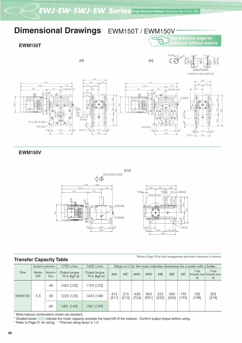
69
一段減速 (減速比1/10~1/60)Single Reduction Reducer (Reduction ratio 1/10 to 1/60)
Dimensional Drawings EWM150T / EWM150V
EWM150T
EWM150V
Transfer Capacity Table*Refer to Page 29 for shaft arrangements and relative direction of rotation.
Size
Standard combination 1750 r/min 1450 r/min Values in ( ) for the motor indicates dimensions for a motor with a brake.
MotorkW
ReductionRatio
Output torque N·m (kgf·m)
Output torque N·m (kgf·m) MA MC MW1 MW MB MD MT
T typeEstimated mass
kg
V typeEstimated mass
kg
EWM150 5.5
40 1003 (102) 1193 (122)
413(511)
215(215)
628(726)
803(901)
252(252)
300(300)
190(193)
182(198)
202(218)50 1225 (125) 1453 (148)
60 1401 (143) 1561 (159)
* Motor/reducer combinations shown are standard.* Shaded boxes indicate the motor capacity exceeds the input kW of the reducer. Confi rm output torque before using.* Refer to Page 21 for sizing. * Thermal rating factor is 1.0.
[R] [H]
4-22キリ
2-M12タップ 深さ24
18×11キー
オイルゲージ
プレッシャベント
ドレンプラグ
29229 29
350
36
30
150
150
180
480
17823 23
224
361
246 115
118128
126
110
φ65h7
MD
MC
175
16
MA
MB
MT
MW1
MW
出力軸穴部詳細
φ83.5
φ115
30。
φ81
80 90 808 2.7
4
φ83.5
φ11530°
82.7
4
85.4
22Js9
φ80H8
30
150
150
180
480
17823 23
224
125 125
250
φ115
4-22キリ
オイルゲージ
MTプレッシャベント
ドレンプラグ
29229 29
350
MD
MC
175
16
MA
MB
MW1
MW
2-M12 tap, 24 deep
Drain plug
Pressure vent
Oil gauge
18 x 11 keyway
4-φ22Drain plug
Oil gauge
Pressure vent
Details of output shaft hole
4-φ22
[LU]
4-24キリ
2-M12タップ 深さ24
18×11キープレッシャベント
φ65h7
225 12525 45420
150 180150480
110
126
128
118246
167
413
30
36
(44)
MT
オイルゲージ
ドレンプラグ
30025 25350
MD
MC175
MA
MB
172
MW1MW
2-M12 tap, 24 deep
Drain plug
Oil gauge
Pressure vent18 x 11 keyway
4-φ24
See previous page for reducers without motors

70
3Eつばき PDF図面ライブラリーTSUBAKI EMERSON PDF Drawing Library Search
EWJ
/ EW
/ SW
J / S
W S
erie
s
Size
Standard combination 1750 r/min 1450 r/min Values in ( ) for the motor indicates dimensions for a motor with a brake.
MotorkW
ReductionRatio
Output torque N·m (kgf·m)
Output torque N·m (kgf·m) MA MC MW1 MW MB MD MT
Estimatedmasskg
SWM150 5.5
40 1003 (102) 1193 (122)
413(511)
215(215)
628(726)
832(930)
252(252)
300(300)
190(193)
166(182)50 1225 (125) 1453 (148)
60 1401 (143) 1561 (159)
* Motor/reducer combinations shown are standard.* Shaded boxes indicate the motor capacity exceeds the input kW of the reducer. Confi rm output torque before using.* Refer to Page 21 for sizing. * Thermal rating factor is 1.0.
Dimensional Drawings SWM150T / SWM150B / SWM150V
SWM150T
SWM150B
SWM150V
Transfer Capacity Table*Refer to Page 29 for shaft arrangements and relative direction of rotation.
出力軸穴部詳細
φ83.5
φ115
30。
φ81
80 90 808 2.7
4
φ83.5
φ11530°
82.7
4
85.4
22Js9
φ80H8
[T-SLF][T-LF]
6
ドレンプラグ 8-M12 タップ深さ25 等配(PCD300)
プレッシャベントオイルゲージ(反対側)
173
15097
420
MD
16MC
204MA
MB
MW1MW
φ335
φ270H7
φ115
125125250
MT
173
15097
420
MD
MB
16MC MA
MW1204MW
125 121プレッシャベント
36
オイルゲージ(反対面)
ドレンプラグ2-M12 タップ深さ248-M12 タ ップ深さ25 等配(PCD300)
110126
φ335
φ270H7
6
10
φ65h7
115
10×8キー
MT
240Details of output shaft hole
Pressure ventOil gauge(Opposite side)
Drain plug8-M12 tap, 25 deepevenly spaced
Pressure ventOil gauge(Opposite side)
10 x 8 keyway
2-M12 tap, 24 deep Drain plug
8-M12 tap, 25 deep evenly spaced
[B-SLF][B-LF]
出力軸穴部詳細
φ83.5
φ115
30。
φ81
80 90 808 2.7
4
φ83.5
φ11530°
82.7
4
85.4
22Js9
φ80H8
6
MT
8-M12 タップ深さ25 等配(PCD300)
ドレンプラグ
オイルゲージ(反対側)
204
173
150
97420 MD
16MC MA
MB
MW1プレッシャベント125125
250
φ335
φ270H7
φ115
125204
173
150
97420 MD
16
MB
MC MAMW1
MW
MT
18×11キー
φ65h710
6
φ270H7
φ335
126110
8-M12 タ ップ深さ25 等配(PCD300)
2-M12 タップ深さ24
ドレンプラグオイルゲージ(反対面)
プレッシャベント
36
121115240
Pressure vent
Details of output shaft hole
Oil gauge(Opposite side)
Drain plug
8-M12 tap, 25 deep evenly spaced
Pressure vent2-M12 tap, 24 deep
18 x 11 keyway
Oil gauge(Opposite side)
Drain plug
8-M12 tap, 25 deep evenly spaced
出力軸穴部詳細
φ83.5
φ115
30。
φ81
80 90 808 2.7
4
φ83.5
φ11530°
82.7
4
85.4
22Js9
φ80H8
[V-SLF][V-LF]
プレッシャベント
ドレンプラグ
地天
オイルゲージ
125125250
φ335
φ270H7
φ115
6
173
150
97420
MT
8-M12 タップ深さ25 等配(PCD300)
204
MD
16MC MA
MB
MW1MW
地天
125
MT
ドレンプラグ
プレッシャベント
110126
φ65h7
18×11キー
106
115 121240 204
173
150
97420
MD
16
MB
MC MAMW1
MW
36
オイルゲージ
ドレンプラグ
2-M12 タップ深さ24
8-M12 タ ップ深さ25等配(PCD300)
φ335
φ270H7
Top BottomDetails of output shaft hole
Drain plug
Oil gauge
Pressure vent
8-M12 tap, 25 deep evenly spaced
Pressure vent
Top Bottom
Drain plug
18 x 11 keyway
Oil gauge2-M12 tap, 24 deep
Drain plug
8-M12 tap, 25 deep evenly spaced
Single
Red
uctio
n Ge
ar Re
duce
rsSp
ecifi c
ation
s
Single
Red
uctio
n Ge
ar Re
duce
rsSiz
e 42
Single
Red
uctio
n Ge
ar Re
duce
rsSiz
e 50
Single
Red
uctio
n Ge
ar Re
duce
rsSiz
e 63
Single
Red
uctio
n Ge
ar Re
duce
rsSiz
e 70
Single
Red
uctio
n Ge
ar Re
duce
rsSiz
e 80
Single
Red
uctio
n Ge
ar Re
duce
rsSiz
e 100
Single
Red
uctio
n Ge
ar Re
duce
rsSiz
e 125
Sing
le R
educ
tion
Gear
Red
ucer
sSi
ze15
0
Sing
le R
educ
tion
Gear
Red
ucer
sSi
ze17
5
Sing
le R
educ
tion
Gear
Red
ucer
sSi
ze20
0
Single
Red
uctio
n Ge
ar Re
duce
rsSiz
e 25/3
5
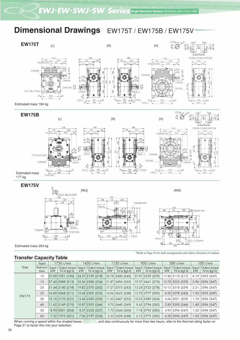
71
一段減速 (減速比1/10~1/60)Single Reduction Reducer (Reduction ratio 1/10 to 1/60)
Dimensional Drawings EW175T / EW175B / EW175V
EW175T
Estimated mass 184 kg
EW175B
Estimated mass 177 kg
EW175V
Estimated mass 204 kg
SizeInput 1750 r/min 1450 r/min 1150 r/min 950 r/min 500 r/min 100 r/min
ReductionRatio
Input Output torque Input Output torque Input Output torque Input Output torque Input Output torque Input Output torquekW N·m (kgf·m) kW N·m (kgf·m) kW N·m (kgf·m) kW N·m (kgf·m) kW N·m (kgf·m) kW N·m (kgf·m)
EW175
10 37.09 1921 (196) 34.37 2139 (218) 30.78 2400 (245) 27.07 2539 (259) 17.86 3110 (317) 4.19 3395 (347)
15 27.43 2088 (213) 25.06 2288 (234) 21.87 2496 (255) 19.27 2641 (270) 12.78 3223 (329) 2.96 3396 (347)
20 21.44 2140 (218) 19.82 2370 (242) 17.27 2575 (263) 15.24 2725 (278) 10.15 3318 (339) 2.31 3396 (347)
25 16.85 2068 (211) 15.68 2302 (235) 14.36 2625 (268) 12.70 2777 (283) 8.50 3378 (345) 1.93 3395 (347)
30 15.16 2170 (221) 13.46 2300 (235) 11.63 2467 (252) 10.23 2589 (264) 6.66 3031 (309) 1.74 3396 (347)
40 11.62 2149 (219) 10.87 2393 (244) 9.70 2640 (269) 8.62 2794 (285) 5.89 3390 (346) 1.40 3396 (347)
50 8.93 2001 (204) 8.37 2228 (227) 7.75 2544 (260) 7.18 2795 (285) 4.95 3396 (347) 1.20 3396 (347)
60 7.52 1973 (201) 7.06 2197 (224) 6.35 2428 (248) 6.12 2773 (283) 4.28 3396 (347) 1.05 3396 (347)
When running a speed within the shaded boxes , and also continuously for more than two hours, refer to the thermal rating factor on Page 21 to factor this into your selection.
Transfer Capacity Table*Refer to Page 29 for shaft arrangements and relative direction of rotation.
[L] [R] [H]
2-M12タップ 深さ24
14×9キー
プレッシャベント
ドレンプラグ
201234 95
9075
329530
33633 33402
36
φ45h7
オイルゲージ
20226 26254
34
180
175
200
555
135 135270
φ125
プレッシャベント201
234 95
9075
329530
33633 33402
φ45h7
オイルゲ-ジ
ドレンプラグ(反対側)
4-22キリ
14×9キー
出力軸穴部詳細
30°
φ93.5
φ125
9 3.290 90 90
4
30° φ125
φ93.5
93.2
4φ90H825Js9
95.4
φ91
142 142133 133Pressure vent
Oil gauge
2-M12 tap, 24 deep
14 x 9 keyway
Drain plug20 x 12 keyway
4-φ22
Oil gauge
4-φ224-φ22
20 x 12 keyway
Pressure vent
14 x 9 keyway
Drain plug
Details of output shaft hole
[L] [H][R]
20226 26254
34 180
175
200
555
135 135270
φ125
201234 95
9075
329530
33633 33402
φ45h7
プレッシャベント
オイルゲージ
ドレンプラグ(反対側)
4-22キリ
14×9キー
出力軸穴部詳細
30°
φ93.5
φ125
9 3.290 90 90
4
30° φ125
φ93.5
93.2
4φ90H825Js9
95.4
φ91
142 142133 133Pressure vent
2-M12 tap, 24 deep
Oil gauge
Drain plug
14 x 9 keyway
4-φ22
20 x 12 keyway
20 x 12 keyway
4-φ224-φ22
Drain plug
Oil gauge
Pressure vent
14 x 9 keyway
Details of output shaft hole
[RU] [RD]
142
133
2-M12タップ 深さ24
36
2-M12 tap, 24 deep
Oil gaugeDrain plug
14 x 9 keyway
20 x 12 keyway
4-φ24
Pressure vent
Pressure vent
4-φ2420 x 12 keyway
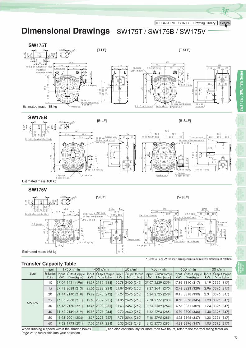
72
3Eつばき PDF図面ライブラリーTSUBAKI EMERSON PDF Drawing Library Search
EWJ
/ EW
/ SW
J / S
W S
erie
s
Dimensional Drawings SW175T / SW175B / SW175V
SW175T
Estimated mass 168 kg
SW175B
Estimated mass 168 kg
SW175V
Estimated mass 168 kg
SizeInput 1750 r/min 1450 r/min 1150 r/min 950 r/min 500 r/min 100 r/min
ReductionRatio
Input Output torque Input Output torque Input Output torque Input Output torque Input Output torque Input Output torquekW N·m (kgf·m) kW N·m (kgf·m) kW N·m (kgf·m) kW N·m (kgf·m) kW N·m (kgf·m) kW N·m (kgf·m)
SW175
10 37.09 1921 (196) 34.37 2139 (218) 30.78 2400 (245) 27.07 2539 (259) 17.86 3110 (317) 4.19 3395 (347)
15 27.43 2088 (213) 25.06 2288 (234) 21.87 2496 (255) 19.27 2641 (270) 12.78 3223 (329) 2.96 3396 (347)
20 21.44 2140 (218) 19.82 2370 (242) 17.27 2575 (263) 15.24 2725 (278) 10.15 3318 (339) 2.31 3396 (347)
25 16.85 2068 (211) 15.68 2302 (235) 14.36 2625 (268) 12.70 2777 (283) 8.50 3378 (345) 1.93 3395 (347)
30 15.16 2170 (221) 13.46 2300 (235) 11.63 2467 (252) 10.23 2589 (264) 6.66 3031 (309) 1.74 3396 (347)
40 11.62 2149 (219) 10.87 2393 (244) 9.70 2640 (269) 8.62 2794 (285) 5.89 3390 (346) 1.40 3396 (347)
50 8.93 2001 (204) 8.37 2228 (227) 7.75 2544 (260) 7.18 2795 (285) 4.95 3396 (347) 1.20 3396 (347)
60 7.52 1973 (201) 7.06 2197 (224) 6.35 2428 (248) 6.12 2773 (283) 4.28 3396 (347) 1.05 3396 (347)
When running a speed within the shaded boxes , and also continuously for more than two hours, refer to the thermal rating factor on Page 21 to factor this into your selection.
Transfer Capacity Table*Refer to Page 29 for shaft arrangements and relative direction of rotation.
14×9キ-
(PCD350)8-M14タップ 深さ30 等配
プレッシャベント
ドレンプラグ
(反対側)オイルゲ-ジ 90
75
φ45h7
203
175
115
493
φ385
φ320H7
φ125
5
135 135270
95234329234
563
出力軸穴部詳細
30°
φ93.5
φ125
9 3.290 90 90
4
30° φ125
φ93.5
93.2
4φ90H825Js9
95.4
φ91
[T-SLF][T-LF]
9075
φ45h7
203
175
115
493
135 13595234329234
563410
2-M12タップ 深さ248-M14タップ 深さ30 等配(PCD350)
オイルゲージ(反対側)
ドレンプラグ
14×9キー
20×12キー
140
120
プレッシャベント
φ70h7
36
φ320H7
φ385
135
5
2
Details of output shaft holeOil gauge(Opposite side)
Pressure vent
14 x 9 keyway
Drain plug
8-M14 tap, 30 deep evenly spaced
Oil gauge(Opposite side)
Pressure vent
14 x 9 keyway
20 x 12 keyway
8-M14 tap, 30 deep evenly spaced
2-M12 tap, 24 deep Drain plug
出力軸穴部詳細
14×9キ-
(PCD350)8-M14タップ 深さ30 等配プレッシャベント
ドレンプラグ(反対側)オイルゲ-ジ
9075
φ45h7
30°
φ93.5
φ125
9 3.290 90 90
4
30° φ125
φ93.5
93.2
4φ90H825Js9
95.4
φ91
203
175
115
493
234 95329234
563
135 135270
φ385
φ320H7
φ125
5
9075
φ45h7
203
175
115
493
234 95329234
563
135
φ385
φ320H7
36
φ70h7
プレッシャベント
120
5
20×12キー14×9キー
ドレンプラグオイルゲージ(反対側)
8-M14タップ 深さ30 等配(PCD350)
2-M12タップ 深さ24 410135140
2
[B-SLF][B-LF]
Details of output shaft hole
(Opposite side)Oil gauge Drain plug Drain plug
14 x 9 keyway
Pressure vent8-M14 tap, 30 deep evenly spaced
2-M12 tap, 24 deep
(Opposite side)Oil gauge
14 x 9 keyway 20 x 12 keyway
Pressure vent8-M14 tap, 30 deep evenly spaced
14×9キー
(PCD350)8-M14タップ 深さ30 等配
オイルゲージ
プレッシャベント
ドレンプラグ地 天
9075
φ45h7
203
175
115
493
234 95329234
563
135 135270
φ385
φ320H7
φ125
5
(φ35)
(175)
155
160
234329234
563
出力軸穴部詳細
30°
φ93.5
φ125
9 3.290 90 90
430° φ
125
φ93.5
93.2
4φ90H825Js9
95.4
φ91
[V-SLF][V-LF]
地 天
9075
φ45h7
203
175
115
493
234 95329234
563
135 135
(φ35)
(175)
155
160
410
2-M12タップ 深さ24 8-M14タップ 深さ30 等配(PCD350)
オイルゲージ(反対側)
14×9キー 20×12キー
140
120 プレッシャベント
φ70h7
36
φ320H7
φ385
ドレンプラグ 135
52
Details of output shaft hole
Oil gauge
14 x 9 keyway
Drain plug8-M14 tap, 30 deep evenly spaced
Bottom Top
Pressure vent
2-M12 tap, 24 deep Drain plug
8-M14 tap, 30 deep evenly spaced
Bottom Top
Pressure vent
Oil gauge
14 x 9 keyway 20 x 12 keywaySin
gle R
educ
tion
Gear
Redu
cers
Spec
ifi cati
ons
Single
Red
uctio
n Ge
ar Re
duce
rsSiz
e 42
Single
Red
uctio
n Ge
ar Re
duce
rsSiz
e 50
Single
Red
uctio
n Ge
ar Re
duce
rsSiz
e 63
Single
Red
uctio
n Ge
ar Re
duce
rsSiz
e 70
Single
Red
uctio
n Ge
ar Re
duce
rsSiz
e 80
Single
Red
uctio
n Ge
ar Re
duce
rsSiz
e 100
Single
Red
uctio
n Ge
ar Re
duce
rsSiz
e 125
Single
Red
uctio
n Ge
ar Re
duce
rsSiz
e 150
Sing
le R
educ
tion
Gear
Red
ucer
sSi
ze17
5
Sing
le R
educ
tion
Gear
Red
ucer
sSi
ze20
0
Single
Red
uctio
n Ge
ar Re
duce
rsSiz
e 25/3
5

73
一段減速 (減速比1/10~1/60)Single Reduction Reducer (Reduction ratio 1/10 to 1/60)
Dimensional Drawings EW200T / EW200B / EW200V
EW200T
Estimated mass 314 kg
EW200B
Estimated mass 304 kg
EW200V
Estimated mass 354 kg
SizeInput 1750 r/min 1450 r/min 1150 r/min 950 r/min 500 r/min 100 r/min
ReductionRatio
Input Output torque Input Output torque Input Output torque Input Output torque Input Output torque Input Output torquekW N·m (kgf·m) kW N·m (kgf·m) kW N·m (kgf·m) kW N·m (kgf·m) kW N·m (kgf·m) kW N·m (kgf·m)
EW200
10 50.13 2597 (265) 46.43 2892 (295) 42.28 3301 (337) 39.17 3682 (376) 26.44 4613 (471) 7.05 5704 (582)
15 36.95 2813 (287) 34.28 3132 (320) 31.29 3576 (365) 28.46 3907 (399) 18.91 4776 (487) 4.99 5703 (582)
20 28.93 2888 (295) 26.88 3216 (328) 24.59 3671 (375) 22.49 4025 (411) 15.01 4910 (501) 3.92 5704 (582)
25 22.86 2804 (286) 21.27 3122 (319) 19.49 3564 (364) 18.16 3975 (406) 12.56 4992 (509) 3.27 5704 (582)
30 20.38 2916 (298) 19.00 3247 (331) 17.29 3671 (375) 15.21 3855 (393) 9.94 4526 (462) 2.95 5704 (582)
40 15.67 2894 (295) 14.65 3223 (329) 13.51 3680 (376) 12.66 4105 (419) 8.71 5018 (512) 2.39 5703 (582)
50 12.11 2709 (276) 11.35 3017 (308) 10.50 3444 (352) 9.87 3842 (392) 7.41 5073 (518) 2.06 5703 (582)
60 10.15 2646 (270) 9.53 2947 (301) 8.85 3365 (343) 8.34 3754 (383) 6.55 5137 (524) 1.83 5703 (582)
When running a speed within the shaded boxes , and also continuously for more than two hours, refer to the thermal rating factor on Page 21 to factor this into your selection.
Transfer Capacity Table
[L] [R] [H]
2-M12タップ 深さ24
14×9キー
プレッシャベント
ドレンプラグ
45
φ48h7
37637 37450
225115262
377602
90110
オイルゲージ
4-26キリ
200
200
235
635
23030 30290
37
147 147294
φ48h7
37637 37450
225115262
377602
90110
14×9キー
ドレンプラグ
オイルゲージ
プレッシャベント
出力軸穴部詳細
30°
φ103.5
φ145
995 100 953.2
4
30° φ103.5
φ145
93.2
4
φ100H828Js9
106.4
φ101
Details of output shaft hole
Pressure vent
Oil gauge
2-M12 tap, 24 deep
14 x 9 keyway
Drain plug22 x 14 keyway
4-φ26 4-φ26
22 x 14 keyway
Oil gauge
14 x 9 keyway
Drain plug
4-φ26
Pressure vent
[L] [R] [H]
23030 30290
200
200
235
635
37
147 147294
4-26キリ37637 37450
90110
377225602
φ48h7
115262
オイルゲージ
ドレンプラグ
14×9キー
プレッシャベント
出力軸穴部詳細
30°
φ103.5
φ145
995 100 953.2
4
30° φ103.5
φ145
93.2
4
φ100H828Js9
106.4
φ101
Details of output shaft hole
Pressure vent
2-M12 tap, 24 deepOil gauge
Drain plug
14 x 9 keyway
22 x 14 keyway
4-φ26
22 x 14 keyway
4-φ26
Oil gauge
Drain plug
Pressure vent
14 x 9 keyway
4-φ26
[RU] [RD]2-M12タップ 深さ24
45
2-M12 tap, 24 deep
Oil gauge
14 x 9 keyway
Drain plug
22 x 14 keywayPressure vent
4-φ26
Pressure vent
4-φ26 22 x 14 keyway
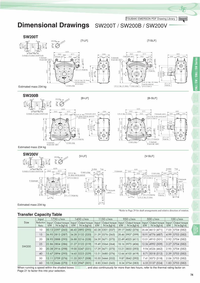
74
3Eつばき PDF図面ライブラリーTSUBAKI EMERSON PDF Drawing Library Search
EWJ
/ EW
/ SW
J / S
W S
erie
s
Dimensional Drawings SW200T / SW200B / SW200V
SW200T
Estimated mass 234 kg
SW200B
Estimated mass 234 kg
SW200V
Estimated mass 234 kg
SizeInput 1750 r/min 1450 r/min 1150 r/min 950 r/min 500 r/min 100 r/min
ReductionRatio
Input Output torque Input Output torque Input Output torque Input Output torque Input Output torque Input Output torquekW N·m (kgf·m) kW N·m (kgf·m) kW N·m (kgf·m) kW N·m (kgf·m) kW N·m (kgf·m) kW N·m (kgf·m)
SW200
10 50.13 2597 (265) 46.43 2892 (295) 42.28 3301 (337) 39.17 3682 (376) 26.44 4613 (471) 7.05 5704 (582)
15 36.95 2813 (287) 34.28 3132 (320) 31.29 3576 (365) 28.46 3907 (399) 18.91 4776 (487) 4.99 5703 (582)
20 28.93 2888 (295) 26.88 3216 (328) 24.59 3671 (375) 22.49 4025 (411) 15.01 4910 (501) 3.92 5704 (582)
25 22.86 2804 (286) 21.27 3122 (319) 19.49 3564 (364) 18.16 3975 (406) 12.56 4992 (509) 3.27 5704 (582)
30 20.38 2916 (298) 19.00 3247 (331) 17.29 3671 (375) 15.21 3855 (393) 9.94 4526 (462) 2.95 5704 (582)
40 15.67 2894 (295) 14.65 3223 (329) 13.51 3680 (376) 12.66 4105 (419) 8.71 5018 (512) 2.39 5703 (582)
50 12.11 2709 (276) 11.35 3017 (308) 10.50 3444 (352) 9.87 3842 (392) 7.41 5073 (518) 2.06 5703 (582)
60 10.15 2646 (270) 9.53 2947 (301) 8.85 3365 (343) 8.34 3754 (383) 6.55 5137 (524) 1.83 5703 (582)
When running a speed within the shaded boxes , and also continuously for more than two hours, refer to the thermal rating factor on Page 21 to factor this into your selection.
Transfer Capacity Table*Refer to Page 29 for shaft arrangements and relative direction of rotation.
出力軸穴部詳細
(PCD380)8-M16タップ 深さ30 等配
プレッシャベント
ドレンプラグ
(反対側)オイルゲ-ジ
14×9キ-
90110
φ48h7
30°
φ103.5
φ145
995 100 953.2
4
30° φ103.5
φ145
93.2
4
φ100H828Js9
106.4
φ420
φ340H7
φ145
5
223
200
120
543
φ101
262 115377262
639
145 145290
[T-SLF][T-LF]
90110
φ48h7
223
200
120
543
262 115377262
639
145
14×9キー
オイルゲージ(反対側)
ドレンプラグ2-M12タップ 深さ24 8-M16タ ップ 深さ30 等配(PCD380)
22×14キー
プレッシャベント 184
φ80h7
170150
5
483
45
φ340H7
φ420
154Details of output shaft holeOil gauge(Opposite side)
Pressure vent
14 x 9 keyway
Drain plug
8-M16 tap, 30 deep evenly spaced
Oil gauge(Opposite side)
Pressure vent
2-M12 tap, 24 deep Drain plug
14 x 9 keyway
8-M16 tap, 30 deep evenly spaced 22 x 14
keyway
出力軸穴部詳細
30°
φ103.5
φ145
995 100 953.2
4
30° φ103.5
φ145
93.2
4
φ100H828Js9
106.4
φ101
(PCD380)8-M16タップ 深さ30 等配
プレッシャベント
ドレンプラグ(反対側)オイルゲ-ジ
14×9キ-
90110
φ48h7
145 145290
φ420
φ340H7
φ145
5
262 115377262
639
223
200
120
543
[B-SLF][B-LF]
90110
φ48h7
145
φ420
φ340H7
262 115377262
639
223
200
120
543 45
154483
5
145
150170
φ80h7
184プレッシャベント
22×14キー
8-M16タ ップ 深さ30 等配(PCD380)
2-M12タップ 深さ24
ドレンプラグ オイルゲージ(反対側)
14×9キー
Details of output shaft hole
Oil gauge(Opposite side)
Drain plug
14 x 9 keyway
Pressure vent8-M16 tap, 30 deep evenly spaced
2-M12 tap, 24 deep
Drain plug
Pressure vent8-M16 tap, 30 deep evenly spaced
14 x 9 keyway22 x 14 keyway
Oil gauge(Opposite side)
(PCD380)8-M16タップ 深さ30 等配
プレッシャベント
ドレンプラグ
オイルゲージ
14×9キー
地 天
90110
φ48h7
145 145290
5
262 115377262
639
223
200
120
543
165
(179)
(φ35)
170
φ145
φ420
φ340H7
262 1377262
639
出力軸穴部詳細
30°
φ103.5
φ145
995 100 953.2
430° φ1
03.5
φ145
93.2
4
φ100H828Js9
106.4
φ101
[V-SLF][V-LF]
地 天
90110
φ48h7
145 154262 115377262
639
223
200
120
543
165
(179)
(φ35)
170
オイルゲージ(反対側) ドレンプラグ
2-M12タップ 深さ24
8-M16タ ップ 深さ30 等配(PCD380)
22×14キー
プレッシャベント
184
φ80h7
170150
5
483
45
φ340H7
φ420
14×9キー
Details of output shaft hole
Oil gauge
14 x 9 keyway
Drain plug8-M16 tap, 30 deep evenly spaced
Bottom Top
Pressure vent
Oil gaugeDrain plug
8-M16 tap, 30 deep evenly spaced
2-M12 tap, 24 deep14 x 9 keyway
22 x 14 keyway
Bottom Top
Pressure vent
Single
Red
uctio
n Ge
ar Re
duce
rsSp
ecifi c
ation
s
Single
Red
uctio
n Ge
ar Re
duce
rsSiz
e 42
Single
Red
uctio
n Ge
ar Re
duce
rsSiz
e 50
Single
Red
uctio
n Ge
ar Re
duce
rsSiz
e 63
Single
Red
uctio
n Ge
ar Re
duce
rsSiz
e 70
Single
Red
uctio
n Ge
ar Re
duce
rsSiz
e 80
Single
Red
uctio
n Ge
ar Re
duce
rsSiz
e 100
Single
Red
uctio
n Ge
ar Re
duce
rsSiz
e 125
Single
Red
uctio
n Ge
ar Re
duce
rsSiz
e 150
Single
Red
uctio
n Ge
ar Re
duce
rsSiz
e 175
Sing
le R
educ
tion
Gear
Red
ucer
sSi
ze20
0
Single
Red
uctio
n Ge
ar Re
duce
rsSiz
e 25/3
5

75
一段減速 (減速比1/10~1/60)Single Reduction Reducer (Reduction ratio 1/10 to 1/60)
Memo
Related Documents