CCIE™ and CCDE™ Written Exam Version X.1 Evolving Technologies Study Guide By: Nicholas J. Russo CCIE™ #42518 (RS/SP) CCDE™ #20160041 Revision 1.1 (10 December 2016)

Welcome message from author
This document is posted to help you gain knowledge. Please leave a comment to let me know what you think about it! Share it to your friends and learn new things together.
Transcript
CCIE™ and CCDE™
Written Exam
Version X.1
Evolving Technologies
Study Guide
By: Nicholas J. Russo
CCIE™ #42518 (RS/SP)
CCDE™ #20160041
Revision 1.1 (10 December 2016)
2 Nicholas J. Russo
About the Author
Nicholas (Nick) Russo holds active CCIE certifications in Routing and Switching and Service Provider, as
well as CCDE. Nick authored a comprehensive study guide for the CCIE Service Provider version 4
examination and this document provides updates to the written test for all CCIE/CCDE tracks. Nick also
holds a Bachelor’s of Science in Computer Science, and a minor in International Relations, from the
Rochester Institute of Technology (RIT). Nick lives in Maryland, USA with his wife, Carla, and daughter,
Olivia. For updates to this document and Nick’s other professional publications, please follow the author
on Twitter with the handle @nickrusso42518.
Technical Reviewers: Guilherme Loch Góes, Nathan Wall, and many from the RouterGods community.
This material is not sponsored or endorsed by Cisco Systems, Inc. Cisco, Cisco Systems, CCIE and the CCIE
Logo are trademarks of Cisco Systems, Inc. and its affiliates. The symbol ™ is included in the Logo
artwork provided to you and should never be deleted from this artwork. All Cisco products, features, or
technologies mentioned in this document are trademarks of Cisco. This includes, but is not limited to,
Cisco IOS®, Cisco IOS-XE®, and Cisco IOS-XR®. Within the body of this document, not every instance of
the aforementioned trademarks are combined with the symbols ® or ™ as they are demonstrated above.
THE INFORMATION HEREIN IS PROVIDED ON AN “AS IS” BASIS, WITHOUT ANY WARRANTIES OR
REPRESENTATIONS, EXPRESS, IMPLIED OR STATUTORY, INCLUDING WITHOUT LIMITATION, WARRANTIES
OF NONINFRINGEMENT, MERCHANTABILITY OR FITNESS FOR A PARTICULAR PURPOSE.
Author’s Notes
This book is designed for any CCIE track (as well as the CCDE) that introduces the “Evolving
Technologies” section of the blueprint for the written qualification exam. It is not specific to any
examination track and provides an overview of the three key evolving technologies: Cloud, Software
Defined Networking (SDN), and Internet of Things (IoT). More detailed references are included at the
end of each chapter; candidates are encouraged to review those resources. Italic text represents cited
text from another not created by the author. This is typically directly from a Cisco document, which is
appropriate given that this is a summary of Cisco’s vision on the topics therein.
This book is not an official publication, does not have an ISBN assigned, and is not protected by any
copyright. It is not for sale and is intended for free, unrestricted distribution. The opinions expressed in
this study guide belong to the author and are not necessarily those of Cisco.
3 Nicholas J. Russo
Contents 1. Cloud 4
1.1 Compare and contrast Cloud deployment models 4
1.1.1 Infrastructure, platform, and software services (XaaS) 8
1.1.2 Performance and reliability 9
1.1.3 Security and privacy 11
1.1.4 Scalability and interoperability 13
1.2 Describe Cloud implementations and operations 14
1.2.1 Automation and orchestration 17
1.2.2 Workload mobility 18
1.2.3 Troubleshooting and management 19
1.2.4 OpenStack components 19
1.3 Resources and References 22
2. Network programmability [SDN] 22
2.1 Describe functional elements of network programmability (SDN) and how they interact 26
2.1.1 Controllers 26
2.1.2 APIs 26
2.1.3 Scripting 26
2.1.4 Agents 27
2.1.5 Northbound vs. Southbound protocols 28
2.2 Describe aspects of virtualization and automation in network environments 29
2.2.1 DevOps methodologies, tools and workflows 30
2.2.2 Network/application function virtualization (NFV, AFV) 31
2.2.3 Service function chaining 32
2.2.4 Performance, availability, and scaling considerations 32
2.3 Resources and References 33
3. Internet of Things (IoT) 34
3.1 Describe architectural framework and deployment considerations 34
3.1.1 Performance, reliability and scalability 37
3.1.2 Mobility 38
3.1.3 Security and privacy 38
3.1.4 Standards and compliance 39
3.1.5 Migration 41
3.1.6 Environmental impacts on the network 42
3.2 Resources and References 42
4 Nicholas J. Russo
1. Cloud
Cisco has defined cloud as follows:
IT resources and services that are abstracted from the underlying infrastructure and provided “on-
demand” and “at scale” in a multitenant environment.
Cisco identifies three key components from this definition that differentiate cloud deployments from
ordinary data center (DC) outsourcing strategies:
a. “On-demand” means that resources can be provisioned immediately when needed, released
when no longer required, and billed only when used.
b. “At-scale” means the service provides the illusion of infinite resource availability in order to meet
whatever demands are made of it.
c. “Multitenant environment” means that the resources are provided to many consumers from a
single implementation, saving the provider significant costs.
These distinctions are imported for a few reasons. Some organizations joke that migrating to cloud is
simple; all they have to do is update their on-premises DC diagram with the words “Private Cloud” and
upper management will be satisfied. While it is true that the term “cloud” is often abused, it is
important to differentiate it from a traditional private DC. This is discussed next.
1.1 Compare and contrast Cloud deployment models
Cloud architectures generally come in four variants:
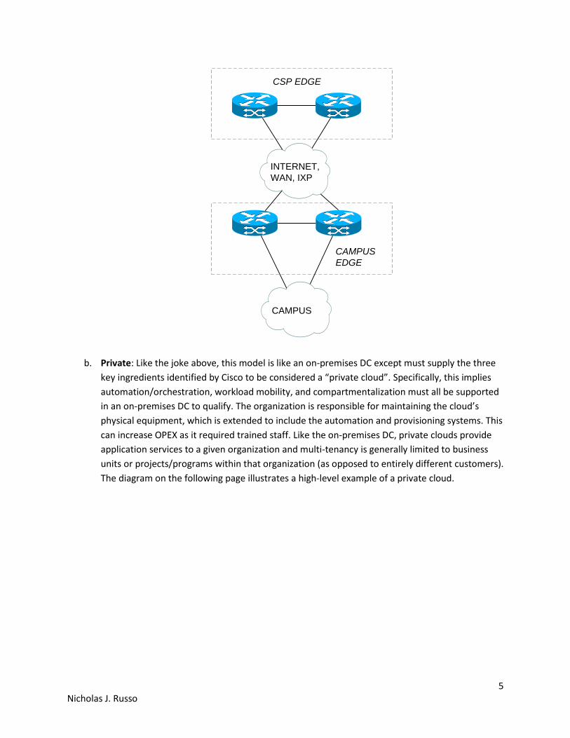
a. Public: Public clouds are generally the type of cloud most people think about when the word
“cloud” is spoken. They rely on a third party organization (off-premise) to provide infrastructure
where a customer pays a subscription fee for a given amount of compute/storage, time, data
transferred, or any other metric that meaningfully represents the customer’s “use” of the cloud
provider’s shared infrastructure. Naturally, the supported organizations do not need to maintain
the cloud’s physical equipment. This is viewed by many businesses as a way to reduce capital
expenses (CAPEX) since purchasing new DC equipment is unnecessary. It can also reduce
operating expenses (OPEX) since the cost of maintaining an on-premise DC, along with trained
staff, could be more expensive than a public cloud solution. A basic public cloud design is shown
on the following page; the enterprise/campus edge uses some kind of transport to reach the
public cloud network.
5 Nicholas J. Russo
CAMPUS
EDGE
CSP EDGE
INTERNET,
WAN, IXP
CAMPUS
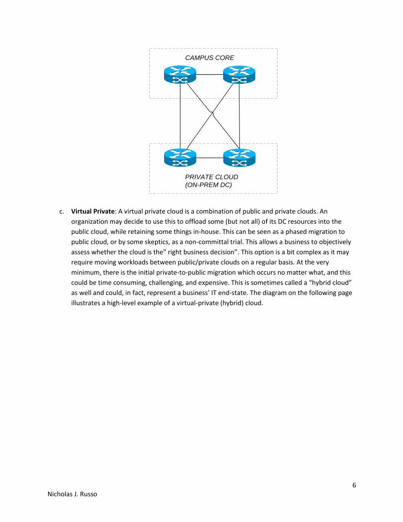
b. Private: Like the joke above, this model is like an on-premises DC except must supply the three
key ingredients identified by Cisco to be considered a “private cloud”. Specifically, this implies
automation/orchestration, workload mobility, and compartmentalization must all be supported
in an on-premises DC to qualify. The organization is responsible for maintaining the cloud’s
physical equipment, which is extended to include the automation and provisioning systems. This
can increase OPEX as it required trained staff. Like the on-premises DC, private clouds provide
application services to a given organization and multi-tenancy is generally limited to business
units or projects/programs within that organization (as opposed to entirely different customers).
The diagram on the following page illustrates a high-level example of a private cloud.
6 Nicholas J. Russo
PRIVATE CLOUD
(ON-PREM DC)
CAMPUS CORE
c. Virtual Private: A virtual private cloud is a combination of public and private clouds. An
organization may decide to use this to offload some (but not all) of its DC resources into the
public cloud, while retaining some things in-house. This can be seen as a phased migration to
public cloud, or by some skeptics, as a non-committal trial. This allows a business to objectively
assess whether the cloud is the” right business decision”. This option is a bit complex as it may
require moving workloads between public/private clouds on a regular basis. At the very
minimum, there is the initial private-to-public migration which occurs no matter what, and this
could be time consuming, challenging, and expensive. This is sometimes called a “hybrid cloud”
as well and could, in fact, represent a business’ IT end-state. The diagram on the following page
illustrates a high-level example of a virtual-private (hybrid) cloud.

7 Nicholas J. Russo
CAMPUS
EDGE
CSP EDGE
INTERNET,
WAN, IXP
PRIVATE CLOUD
(ON-PREM DC)
CAMPUS
d. Inter-cloud: Like the Internet (a non-hierarchical interconnection of various autonomous
systems to exchange network reachability information), Cisco suggests that, in the future, the
contiguity of cloud computing may extend between many third-party organizations. This is
effectively how the Internet works; a customer signs a contract with a given service provider
(SP) yet has access to several thousand other AS resources on the Internet. The same concept
could be applied to cloud and this is an active area of research for Cisco.
Below is a based-on-a-true-story discussion that highlights some of the decisions and constraints
relating to cloud deployments.
a. An organization decides to retain their existing on-premises DC for legal/compliance reasons. By
adding automation/orchestration and multi-tenancy components, they are able to quickly
increase and decrease virtual capacity. Multiple business units or supported organizations are
free to adjust their security policy requirements within the shared DC in a manner that is secure
and invisible to other tenants; this is the result of compartmentalization within the cloud
architecture. This deployment would qualify as a “private cloud”.

8 Nicholas J. Russo
b. Years later, the same organization decides to keep their most important data on-premises to
meet seemingly-inflexible Government regulatory requirements, yet feels that migrating a
portion of their private cloud to the public cloud is a solution to reduce OPEX. This helps
increase the scalability of the systems for which the Government does not regulate, such as
virtualized network components or identity services, as the on-premises DC is bound by CAPEX
reductions. The private cloud footprint can now be reduced as it is used only for a subset of
tightly controlled systems, while the more generic platforms can be hosted from a cloud
provider at lower cost. Note that actually exchanging/migrating workloads between the two
clouds at will is not appropriate for this organization as they are simply trying to outsource
capacity to reduce cost. This deployment could be considered a “virtual private cloud” by Cisco,
but is also commonly referred to as a “hybrid cloud”.
c. Years later still, this organization considers a full migration to the public cloud. Perhaps this is
made possible by the relaxation of the existing Government regulations or by the new security
enhancements offered by cloud providers. In either case, the organization can migrate its
customized systems to the public cloud and consider a complete decommission of their existing
private cloud. Such decommissioning could be done gracefully, perhaps by first shutting down
the entire private cloud and leaving it in “cold standby” before removing the physical racks.
Rather than using the public cloud to augment the private cloud (like a virtual private cloud), the
organization could migrate to a fully public cloud solution.
1.1.1 Infrastructure, platform, and software services (XaaS)
Cisco defines four critical service layers of cloud computing:
a. Software as a Service (SaaS) is where application services are delivered over the network on a
subscription and on-demand basis. A simple example would be to create a document but not
installing the appropriate text editor on a user’s personal computer. Instead, the application is
hosted “as a service” that a user can access anywhere, anytime, from any machine.
b. Platform as a Service (PaaS) consists of run-time environments and software development
frameworks and components delivered over the network on a pay-as-you-go basis. PaaS
offerings are typically presented as API to consumers. Similar to SaaS, PaaS is focused on
providing a complete development environment for computer programmers to test new
applications, typically in the development (dev) phase. Although less commonly used by
organizations using mostly commercial-off-the-shelf (COTS) applications, it is a valuable offering
for organizations developing and maintaining specific, in-house applications.
c. Infrastructure as a Service (IaaS) is where compute, network, and storage are delivered over the
network on a pay-as-you-go basis. The approach that Cisco is taking is to enable service
providers to move into this area. This is likely the first thing that comes to mind when individuals
think of “cloud”. It represents the classic “outsourced DC” mentality that has existed for years

9 Nicholas J. Russo
and gives the customer flexibility to deploy any applications they wish. Compared to SaaS, IaaS
just provides the “hardware”, roughly speaking, while SaaS provides both. IaaS may also provide
a virtualization layer by means of a hypervisor. A good example of an IaaS deployment could be
a miniature public cloud environment within an SP point of presence (POP) which provides
additional services for each customer: firewall, intrusion prevention, WAN acceleration, etc.
d. IT foundation is the basis of the above value chain layers. It provides basic building blocks to
architect and enable the above layers. While more abstract than the XaaS layers already
discussed, the IT foundation is generally a collection of core technologies that evolve over time.
For example, DC virtualization became very popular about 15 years ago and many organizations
spent most of the last decade virtualizing “as much as possible”. DC fabrics have also changed in
recent years; the original designs represented a traditional core/distribution/access layer design
yet the newer designs represent leaf/spine architectures. These are “IT foundation” changes
that occur over time which help shape the XaaS offerings, which are always served using the
architecture defined at this layer.
1.1.2 Performance and reliability
Assessing the performance and reliability of cloud networks presents an interesting set of trade-offs. For
years, network designers have considered creating “failure domains” in the network so as to isolate
faults. With routing protocols, this is conceptually easy to understand, but often times difficult to design
and implement, especially when considering business/technical constraints. Designing a DC comes with
its own set of trade-offs when identifying the “failure domains” (which are sometimes called “availability
zones” within a fabric), but that is outside the scope of this document. The real trade-offs with a cloud
environment revolve around the introduction of automation. Automation is discussed in detail in section
1.2.1 but the trade-offs are discussed here as they directly influence the performance and reliability of a
system. Note that this discussion is typically relevant for private and virtual private clouds, as a public
cloud provider will always be large enough to warrant several automation tools.
Automation usually reduces the total cost of ownership (TCO), which is a desirable thing for any
business. This is the result of reducing the time (and labor wages) it takes for individuals to “do things”:
provision a new service, create a backup, add VLANs to switches, test MPLS traffic-engineering tunnel
computations, etc. The trade-off is that all software (including the automation system being discussed)
requires maintenance, whether that is in the form of in-house development or a subscription fee from a
third-party. If in the form of in-house development, software engineers are paid to maintain and
troubleshoot the software which could potentially be more expensive than just doing things manually,
depending on how much maintenance and unit testing the software requires. Most individuals who
have worked as software developers (including the author) know that bugs or feature requests always
seem to pop up, and maintenance is continuous for any non-trivial piece of code. Businesses must also
consider the cost of the subscription for the automation software against the cost of not having it (in
labor wages). Typically this becomes a simple choice as the network grows; automation often shines
here. This is why automation is such a key component of cloud environments because the cost of
dealing with software maintenance is almost always less than the cost of a large IT staff.

10 Nicholas J. Russo
The main takeaway is that automation should be deployed where it makes sense (TCO reduction) and
where it can be maintained with a reasonable amount of effort. This is how the performance and
reliability of a cloud environment can be maximized. Another key aspect of cloud design is accessibility,
which assumes sufficient network bandwidth to reach the cloud environment. A DC that was once
located at a corporate site with 2,000 employees was accessible to those employees over a company’s
campus LAN architecture. Often times this included high-speed core and DC edge layers whereby
accessing DC resources was fast and highly available. With public cloud, the Internet/private WAN
becomes involved, so cloud access becomes an important consideration.
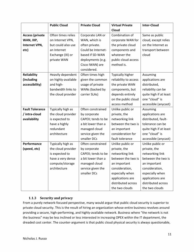
The following page includes a table that compares access methods, reliability, and other characteristics
of the different cloud solutions.
11 Nicholas J. Russo
Public Cloud Private Cloud Virtual Private
Cloud
Inter-Cloud
Access (private
WAN, IXP,
Internet VPN,
etc)
Often times relies
on Internet VPN,
but could also use
an Internet
Exchange (IX) or
private WAN
Corporate LAN or
WAN, which is
often private.
Could be Internet-
based if SD-WAN
deployments (e.g.
Cisco IWAN) are
considered.
Combination of
corporate WAN for
the private cloud
components and
whatever the
public cloud access
method is.
Same as public
cloud, except relies
on the Internet as
transport between
cloud
Reliability
(including
accessibility)
Heavily dependent
on highly-available
and high-
bandwidth links to
the cloud provider
Often times high
given the common
usage of private
WANs (backed by
carrier SLAs)
Typically higher
reliability to access
the private WAN
components, but
depends entirely
on the public cloud
access method
Assuming
applications are
distributed,
reliability can be
quite high if at least
one “cloud” is
accessible (anycast)
Fault Tolerance
/ intra-cloud
availability
Typically high as
the cloud provider
is expected to
have a highly
redundant
architecture
Often constrained
by corporate
CAPEX; tends to be
a bit lower than a
managed cloud
service given the
smaller DCs
Unlike public or
private, the
networking link
between the two is
an important
consideration for
fault tolerance
Assuming
applications are
distributed, fault-
tolerance can be
quite high if at least
one “cloud” is
accessible (anycast)
Performance
(speed, etc)
Typically high as
the cloud provider
is expected to
have a very dense
compute/storage
architecture
Often constrained
by corporate
CAPEX; tends to be
a bit lower than a
managed cloud
service given the
smaller DCs
Unlike public or
private, the
networking link
between the two is
an important
consideration,
especially when
applications are
distributed across
the two clouds
Unlike public or
private, the
networking link
between the two is
an important
consideration,
especially when
applications are
distributed across
the two clouds
1.1.3 Security and privacy
From a purely network-focused perspective, many would argue that public cloud security is superior to
private cloud security. This is the result of hiring an organization whose entire business revolves around
providing a secure, high-performing, and highly-available network. Business where “the network is not
the business” may be less inclined or less interested in increasing OPEX within the IT department, the
dreaded cost center. The counter-argument is that public cloud physical security is always questionable,

12 Nicholas J. Russo
even if the digital security is strong. Should a natural disaster strike a public cloud facility where disk
drives are scattered across a large geographic region (tornado comes to mind), what is the cloud
provider’s plan to protect customer data? What if the data is being stored in a region of the world
known to have unfriendly relations towards the home country of the supported business? These are
important questions to ask because when data is in the public cloud, the customer’s never really know
exactly “where” the data is being stored. This uncertainty can be offset by using “availability zones”
where some cloud providers will ensure the data is confined to a given geographic region. In many
cases, this sufficiently addresses the concern for most customers, but not always. As a customer, it is
also hard to enforce and prove this. This sometimes comes with an additional cost, too.
Privacy in the cloud is achieved mostly by introducing multi-tenancy separation. Compartmentalization
at the host, network, and application layers ensure that the entire cloud architecture keeps data private;
that is to say, customers can never access data from other customers. Sometimes this multi-tenancy can
be done as crudely as separating different customers onto different hosts, which use different VLANs
and are protected behind different virtual firewall contexts. Sometimes the security is integrated with
an application shared by many customers using some kind of public key infrastructure (PKI). Often times
maintaining this security and privacy is a combination of many techniques. Like all things, the security
posture is a continuum which could be relaxed between tenants if, for example, the two of them were
partners and wanted to share information within the same public cloud provider (like a cloud extranet).
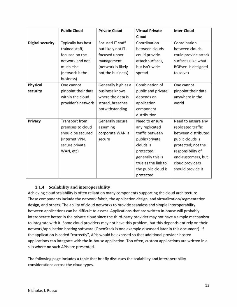
The following page compares the security and privacy characteristics between the different cloud
deployment options.
13 Nicholas J. Russo
Public Cloud Private Cloud Virtual Private
Cloud
Inter-Cloud
Digital security Typically has best
trained staff,
focused on the
network and not
much else
(network is the
business)
Focused IT staff
but likely not IT-
focused upper
management
(network is likely
not the business)
Coordination
between clouds
could provide
attack surfaces,
but isn’t wide-
spread
Coordination
between clouds
could provide attack
surfaces (like what
BGPsec is designed
to solve)
Physical
security
One cannot
pinpoint their data
within the cloud
provider’s network
Generally high as a
business knows
where the data is
stored, breaches
notwithstanding
Combination of
public and private;
depends on
application
component
distribution
One cannot
pinpoint their data
anywhere in the
world
Privacy Transport from
premises to cloud
should be secured
(Internet VPN,
secure private
WAN, etc)
Generally secure
assuming
corporate WAN is
secure
Need to ensure
any replicated
traffic between
public/private
clouds is
protected;
generally this is
true as the link to
the public cloud is
protected
Need to ensure any
replicated traffic
between distributed
public clouds is
protected; not the
responsibility of
end-customers, but
cloud providers
should provide it
1.1.4 Scalability and interoperability
Achieving cloud scalability is often reliant on many components supporting the cloud architecture.
These components include the network fabric, the application design, and virtualization/segmentation
design, and others. The ability of cloud networks to provide seamless and simple interoperability
between applications can be difficult to assess. Applications that are written in-house will probably
interoperate better in the private cloud since the third-party provider may not have a simple mechanism
to integrate with it. Some cloud providers may not have this problem, but this depends entirely on their
network/application hosting software (OpenStack is one example discussed later in this document). If
the application is coded “correctly”, APIs would be exposed so that additional provider-hosted
applications can integrate with the in-house application. Too often, custom applications are written in a
silo where no such APIs are presented.
The following page includes a table that briefly discusses the scalability and interoperability
considerations across the cloud types.
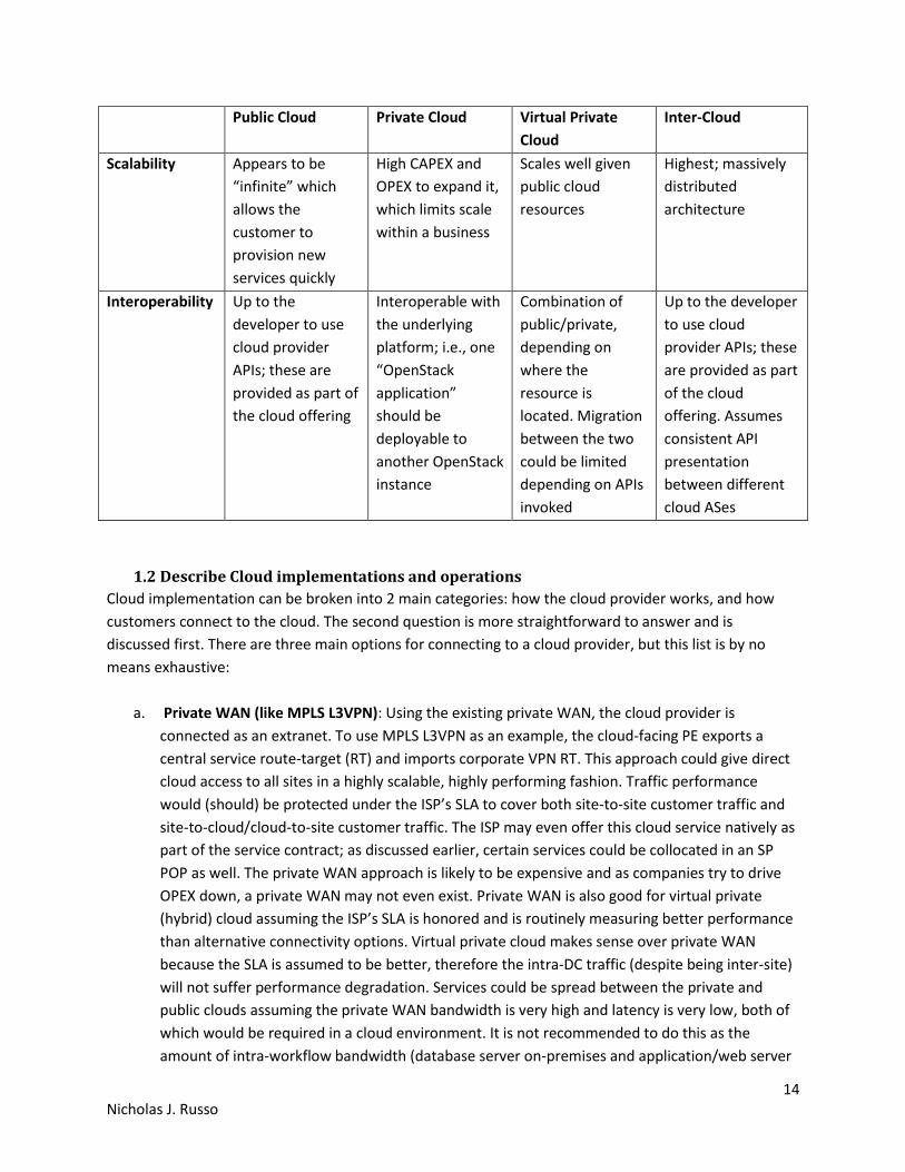
14 Nicholas J. Russo
Public Cloud Private Cloud Virtual Private
Cloud
Inter-Cloud
Scalability Appears to be
“infinite” which
allows the
customer to
provision new
services quickly
High CAPEX and
OPEX to expand it,
which limits scale
within a business
Scales well given
public cloud
resources
Highest; massively
distributed
architecture
Interoperability Up to the
developer to use
cloud provider
APIs; these are
provided as part of
the cloud offering
Interoperable with
the underlying
platform; i.e., one
“OpenStack
application”
should be
deployable to
another OpenStack
instance
Combination of
public/private,
depending on
where the
resource is
located. Migration
between the two
could be limited
depending on APIs
invoked
Up to the developer
to use cloud
provider APIs; these
are provided as part
of the cloud
offering. Assumes
consistent API
presentation
between different
cloud ASes
1.2 Describe Cloud implementations and operations
Cloud implementation can be broken into 2 main categories: how the cloud provider works, and how
customers connect to the cloud. The second question is more straightforward to answer and is
discussed first. There are three main options for connecting to a cloud provider, but this list is by no
means exhaustive:
a. Private WAN (like MPLS L3VPN): Using the existing private WAN, the cloud provider is
connected as an extranet. To use MPLS L3VPN as an example, the cloud-facing PE exports a
central service route-target (RT) and imports corporate VPN RT. This approach could give direct
cloud access to all sites in a highly scalable, highly performing fashion. Traffic performance
would (should) be protected under the ISP’s SLA to cover both site-to-site customer traffic and
site-to-cloud/cloud-to-site customer traffic. The ISP may even offer this cloud service natively as
part of the service contract; as discussed earlier, certain services could be collocated in an SP
POP as well. The private WAN approach is likely to be expensive and as companies try to drive
OPEX down, a private WAN may not even exist. Private WAN is also good for virtual private
(hybrid) cloud assuming the ISP’s SLA is honored and is routinely measuring better performance
than alternative connectivity options. Virtual private cloud makes sense over private WAN
because the SLA is assumed to be better, therefore the intra-DC traffic (despite being inter-site)
will not suffer performance degradation. Services could be spread between the private and
public clouds assuming the private WAN bandwidth is very high and latency is very low, both of
which would be required in a cloud environment. It is not recommended to do this as the
amount of intra-workflow bandwidth (database server on-premises and application/web server
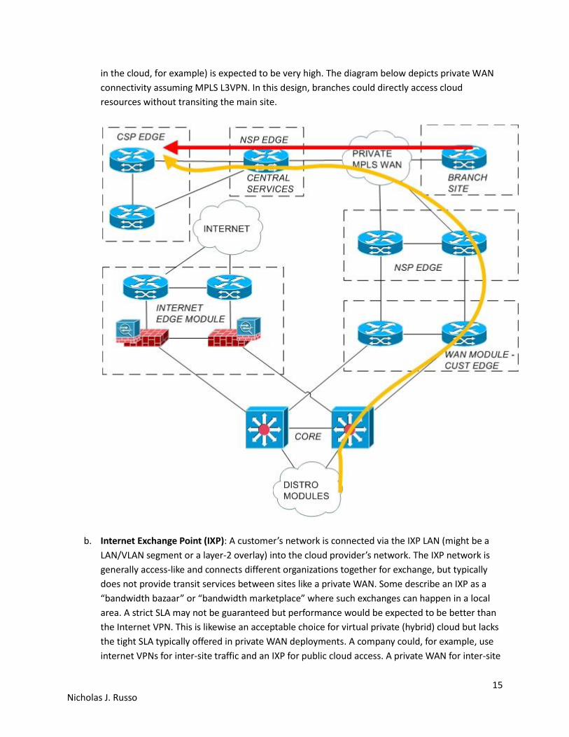
15 Nicholas J. Russo
in the cloud, for example) is expected to be very high. The diagram below depicts private WAN
connectivity assuming MPLS L3VPN. In this design, branches could directly access cloud
resources without transiting the main site.
b. Internet Exchange Point (IXP): A customer’s network is connected via the IXP LAN (might be a
LAN/VLAN segment or a layer-2 overlay) into the cloud provider’s network. The IXP network is
generally access-like and connects different organizations together for exchange, but typically
does not provide transit services between sites like a private WAN. Some describe an IXP as a
“bandwidth bazaar” or “bandwidth marketplace” where such exchanges can happen in a local
area. A strict SLA may not be guaranteed but performance would be expected to be better than
the Internet VPN. This is likewise an acceptable choice for virtual private (hybrid) cloud but lacks
the tight SLA typically offered in private WAN deployments. A company could, for example, use
internet VPNs for inter-site traffic and an IXP for public cloud access. A private WAN for inter-site

16 Nicholas J. Russo
access is also acceptable. The diagram below shows a private WAN for branch connectivity and
an IXP used for cloud connectivity from the main campus site.
c. Internet VPN: By far the most common deployment, a customer creates a secure VPN over the
Internet (could be multipoint if outstations required direct access as well) to the cloud provider.
It is simple and cost effective, both from a WAN perspective and DC perspective, but offers no
SLA whatsoever. Although suitable for most customers, it is likely to be the most inconsistent
performing option. While broadband Internet connectivity is much cheaper than private WAN
bandwidth (in terms of price per Mbps), the quality is often lower. Whether this is “better” is
debatable and depends on the business drivers. Also note that Internet VPNs, even high
bandwidth ones, offer no latency guarantees at all. This option is best for fully public cloud
solutions since the majority of traffic transiting this VPN tunnel should be user service flows. The
solution is likely to be a poor choice for virtual private clouds, especially if workloads are
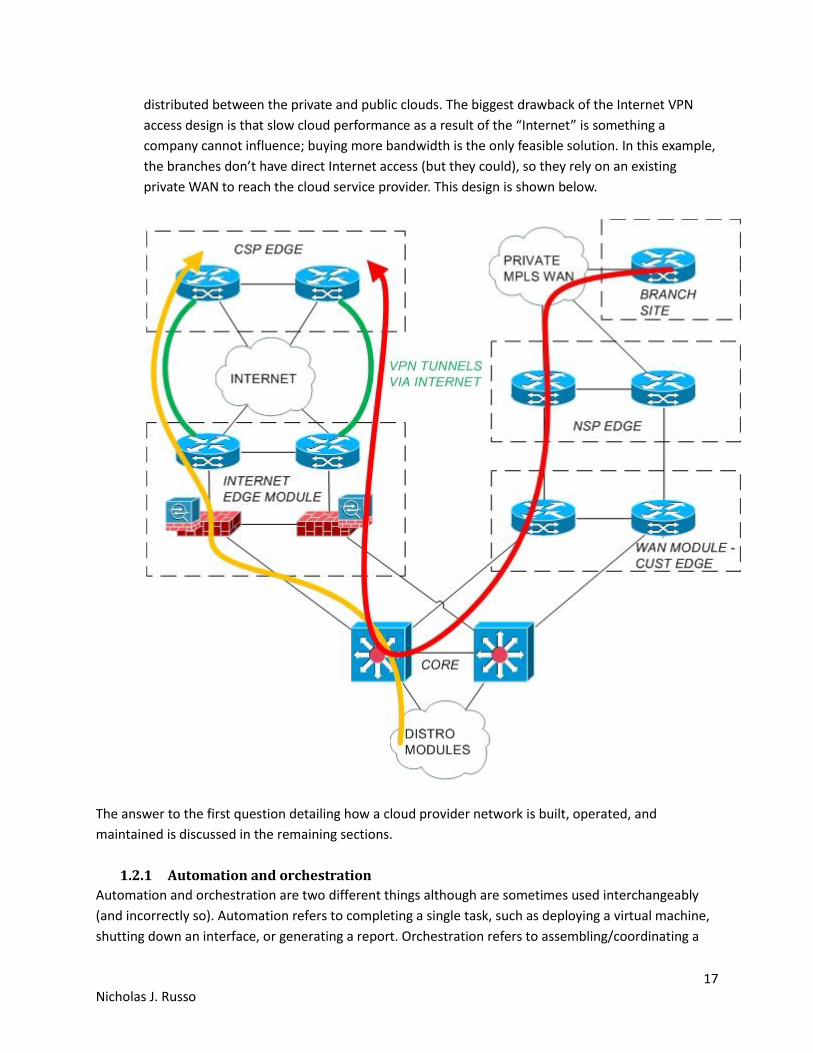
17 Nicholas J. Russo
distributed between the private and public clouds. The biggest drawback of the Internet VPN
access design is that slow cloud performance as a result of the “Internet” is something a
company cannot influence; buying more bandwidth is the only feasible solution. In this example,
the branches don’t have direct Internet access (but they could), so they rely on an existing
private WAN to reach the cloud service provider. This design is shown below.
The answer to the first question detailing how a cloud provider network is built, operated, and
maintained is discussed in the remaining sections.
1.2.1 Automation and orchestration
Automation and orchestration are two different things although are sometimes used interchangeably
(and incorrectly so). Automation refers to completing a single task, such as deploying a virtual machine,
shutting down an interface, or generating a report. Orchestration refers to assembling/coordinating a

18 Nicholas J. Russo
process/workflow, which is effectively and ordered set of tasks glued together with conditions. For
example, deploy this virtual machine, and if it fails, shutdown this interface and generate a report.
Automation is to task as orchestration is to process/workflow.
Often times the task to automate is what an engineer would configure using some
programming/scripting language such as Java, C, Python, Perl, Ruby, etc. The variance in tasks can be
very large since an engineer could be presented with a totally different task every hour. Creating 500
VLANs on 500 switches isn’t difficult, but is monotonous, so writing a short script to complete this task is
ideal. Adding this script as an input for an orchestration engine could properly insert this task into a
workflow. For example, run the VLAN-creation script after the nightly backups but before 6:00 AM the
following day. If it fails, the orchestrator can revert all configurations so that the developer can
troubleshoot any script errors.
1.2.2 Workload mobility
Workload mobility is a generic goal and has been around since the first virtualized DCs were created.
This gives IT administrators an increased ability to share resources amount different workloads within
the virtual DC (which could consist of multiple DCs connected across a Data Center Interconnect, or DCI).
It also allows workloads to be balanced across a collection of resources. For example, if 4 hosts exist in a
cluster, one of them might be performing more than 50% of the computationally-expensive work while
the others are underutilized. The ability to move these workloads is an important capability.
It is important to understand that workload mobility is not necessarily the same thing as VM mobility.
For example, a workload’s accessibility can be abstracted using anycast while the application exists in
multiple availability zones (AZ) spread throughout the cloud provider’s network. Using Domain Name
System (DNS), different application instances can be utilized based on geographic location, time of day,
etc. The VMs have not actually moved but the resource performing the workload may vary.
Although this concept has been around since the initial virtualization deployments, it is even more
relevant in cloud, since the massively scalable and potentially distributed nature of that environment is
abstracted into a single “cloud” entity. Using the cluster example from above, those 4 hosts might not
even be in the same DC, or even within the same cloud provider (as could be the case with Inter-cloud).
The concept of workload mobility needs to be extended large-scale; note that this doesn’t necessarily
imply layer-2 extensions across the globe. It simply implies that the workload needs to be moved or
distributed differently, which can be solved with geographically-based anycast solutions, for example.
As discussed in the automation/orchestration section above, orchestrating workloads is a major goal of
cloud. The individual tasks that are executed in sequence (and conditionally) by the orchestration engine
could be distributed throughout the cloud. The task itself (and the code for it) is likely centralized by the
targets of those tasks, such as a specific container or storage device, could be distributed.
19 Nicholas J. Russo
1.2.3 Troubleshooting and management
One of the fundamental tenets of managing a cloud network is automation. Common scripting
languages, such as Python, can be used to automate a specific management task as discussed in an
earlier section. Other network device management tools, such as Ansible, allow an administrator to
create a custom script and execute it on many devices concurrently. This is one example of the method
by which administrators can directly apply task automation in the workplace.
Other protocols and languages, such as NETCONF and YANG, also help automate/simplify network
management indirectly. NETCONF (RFC6241) is the protocol by which configurations are installed and
changed. YANG (RFC6020) is the modeling language used to represent device configuration and state,
much like Extensible Markup Language (XML). Put simply, NETCONF is the transport vessel for YANG
information to be transferred from a network management system (NMS) to a network device. Although
YANG can be quite complex to humans, it is similar to SNMP; it is simple for machines. YANG is an
abstraction away from network device CLIs which promotes simplified management in cloud
environments and a progressive migration toward one of the SDN models discussed later in this
document. Devices that implement NETCONF/YANG provide a uniform manageability interface which
means vendor hardware/software can be swapped in a network without affecting the management
architecture, operations, or strategy.
A brief discussion on other data modeling languages is worthwhile. While YANG is quite common,
especially when paired with NETCONF, there are easier-to-read alternatives available. One such option is
YAML Ain’t Markup Language (YAML). It solves a similar problem as YANG since it is primarily used for
configuration files, but generally contains a subset of functionality as it was specifically designed to be
simpler.
JavaScript Object Notation (JSON) is another data modeling language that is similar to YAML in concept.
It was designed to be simpler than traditional markup languages and uses key/value pairs to store
information. The “value” of a given pair can be another key/value pair, which enables hierarchical data
nesting. The key/value pair structure and syntax is very similar to the “dictionary” data type in Python.
JSON is even lighter than YAML and is also commonly used for maintaining configuration files.
Troubleshooting a cloud network is often reliant on real-time network analytics. Collecting network
performance statistics is not a new concept, but designing software to intelligently parse, correlate, and
present the information in a human-readable format is constantly evolving. With a good analytics
engine, the NMS can move/provision flows around the network (assuming the network is both
disaggregated and programmable) to resolve any problems. For problems that cannot be resolved
automatically, the issues are brought to the administrator’s attention using these engines. The
administrator can use other troubleshooting tools or NMS features to isolate and repair the fault.
1.2.4 OpenStack components
Before discussing the OpenStack components, background information on OpenStack is provided below.
Although OpenStack seems similar to a hypervisor, it adds additional abstractions for virtual instances to
reduce the management burden on administrators. OpenStack is part of the motion that technology is
20 Nicholas J. Russo
moving “from virtual Machines (VM) to APIs”. VMs allow users to dynamically instantiate a server
abstracted from physical resources, which has been popular for years. The idea of cloud computing (and
specifically OpenStack) is to extend that abstraction to ALL resources (compute, storage, network,
management, etc). All of these things could be managed through APIs rather than vendor-specific
prompts and user interfaces, such as GUIs, CLIs, etc.
The fundamental idea is to change the way IT is consumed (including compute, storage, and network).
The value proposition of this change includes increasing efficiency (peak of sums, not sum of peaks) and
on-demand elastic provisioning (faster engineering processes). For cost reduction in both CAPEX and
OPEX, the cost models generally resemble “pay for what you use”. A customer can lease the space from
a public cloud provider for a variable amount of time. In some cases, entire IT shops might migrate to a
public cloud indefinitely. In others, a specific virtual workload may need to be executed one time for 15
minutes in the public cloud since some computationally-expensive operations may take too long in the
on-premises DC. “Cloud bursting” is an example of utilizing a large amount of cloud resources for a very
short period of time, perhaps to reduce/compress a large chunk of data, which is a one-time event.
OpenStack releases are scheduled every 6 months and many vendors from across the stack contribute
to the code. The entire goal is to have an open-source cloud computing platform; while it may not be as
feature-rich as large-scale public cloud implementations, it is considered a viable and stable alternative.
OpenStack is composed of multiple projects (improved maintainability) which follow a basic process:
a. External: The idea phase
b. Incubated: Project requirements, migrate to OpenStack after 2 milestones of incubation
c. Integrated: Release as part of OpenStack
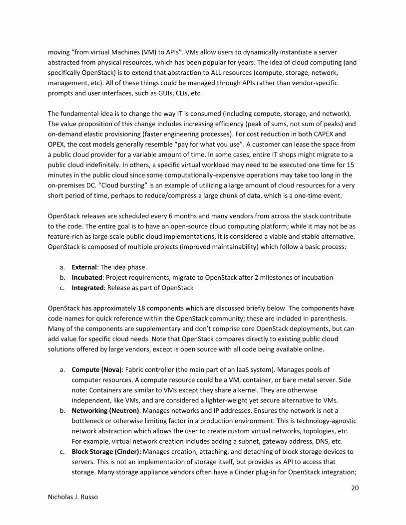
OpenStack has approximately 18 components which are discussed briefly below. The components have
code-names for quick reference within the OpenStack community; these are included in parenthesis.
Many of the components are supplementary and don’t comprise core OpenStack deployments, but can
add value for specific cloud needs. Note that OpenStack compares directly to existing public cloud
solutions offered by large vendors, except is open source with all code being available online.
a. Compute (Nova): Fabric controller (the main part of an IaaS system). Manages pools of
computer resources. A compute resource could be a VM, container, or bare metal server. Side
note: Containers are similar to VMs except they share a kernel. They are otherwise
independent, like VMs, and are considered a lighter-weight yet secure alternative to VMs.
b. Networking (Neutron): Manages networks and IP addresses. Ensures the network is not a
bottleneck or otherwise limiting factor in a production environment. This is technology-agnostic
network abstraction which allows the user to create custom virtual networks, topologies, etc.
For example, virtual network creation includes adding a subnet, gateway address, DNS, etc.
c. Block Storage (Cinder): Manages creation, attaching, and detaching of block storage devices to
servers. This is not an implementation of storage itself, but provides as API to access that
storage. Many storage appliance vendors often have a Cinder plug-in for OpenStack integration;
21 Nicholas J. Russo
this ultimately abstracts the vendor-specific user interfaces from the management process.
Storage volumes can be detached and moved between instances (an interesting form of file
transfer, file example) to share information and migrate data between projects.
d. Identity (Keystone): Directory service contains users mapped to services they can access.
Somewhat similar to group policies applied in corporate deployments. Tenants are stored here
which allows them to access resources/services within OpenStack; commonly this is access to
the OpenStack Dashboard (Horizon) to manage an OpenStack environment.
e. Image (Glance): Provides discovery, registration, and delivery services. These images are like
ordinary images to template new virtual services.
f. Object Storage (Swift): Storage system with built-in data replication and integrity. Objects and
files are written to disk using this interface which manages the I/O details. Scalable and resilient
storage for all objects like files, photos, etc. This means the customer doesn’t have to deploy a
block-storage solution themselves, then manage the storage protocols (iSCSI, NFS, etc).
g. Dashboard (Horizon): The GUI for administrators and users to access, provision, and automate
resources. The dashboard is based on Python Django framework and is layered on top of service
APIs. Logging in relies on Keystone for identity management which secures access to the GUI.
The dashboard supports different tenants (business units, groups/teams, customers, etc) with
separate permissions and credentials; this is effectively role-based access control. The GUI
provides the most basic/common functionality for users without needing CLI access, which is
supported for advanced functions. “Security group” abstractions to enforce access control
(often need to configure this before being able to access the new instances).
h. Orchestration (Heat): Service to orchestrate multiple cloud applications via templates using a
variety of APIs.
i. Workflow (Mistral): Manages user-created workflows which can be triggered manually or by
some event.
j. Telemetry (Ceilometer): Provides a Single Point of Contact for billing systems used within the
cloud environment.
k. Database (Trove): This is a Database-as-a-service provisioning engine.
l. Elastic Map Reduce (Sahara): Automated way to provision Hadoop clusters, like a wizard.
m. Bare Metal (Ironic): Provisions bare metal machines rather than virtual machines.
n. Messaging (Zaqar): Cloud messaging service for Web Developments (full RESTful API) used to
communicate between SaaS and mobile applications.
o. Shared File System (Manila): Provides an API to manage shares in a vendor agnostic fashion
(create, delete, grant/deny access, etc).
p. DNS (Designate): Multi-tenant REST API for managing DNS (DNS-as-a-service).
q. Search (Searchlight): Provides search capabilities across various cloud services and is being
integrated into the Dashboard.
r. Key Manager (Barbican): Provides secure storage, provisioning, and management of secrets
(passwords).
The key components of OpenStack and their interactions are depicted on the following page. The source
of this image is included in the references as it was not created by the author.
22 Nicholas J. Russo
1.3 Resources and References
http://www.cisco.com/c/dam/en_us/solutions/industries/docs/gov/CiscoCloudComputing_WP.pdf
https://en.wikipedia.org/wiki/OpenStack#Components
http://www.cisco.com/c/en/us/solutions/cloud/overview.html
http://www.unleashingit.com/
www.cisco.com/go/cloud
https://www.openstack.org/software/
Understanding Cisco Cloud Fundamentals
Designing Networks and Services for the Cloud
http://getcloudify.org/2014/07/18/openstack-wiki-open-cloud.html
2. Network programmability [SDN]
Software-Defined Networking (SDN) is a concept that networks can be both programmable and
disaggregated concurrently, ultimately providing additional flexibility, intelligence, and customization by
the network administrators. Because the definition of SDNs varies so widely within the network
community, it should be thought of as a continuum of different models rather than a single, prescriptive
solution.
There are four main SDN models as defined in “The Art of Network Architecture: Business-Driven Design”
by Russ White and Denise Donohue (Cisco Press 2015). The models are discussed briefly below.
a. Distributed: Although not really an “SDN” model at all, it is important to understand the status
quo. Network devices today each have their own control-plane components which rely on

23 Nicholas J. Russo
distributed routing protocols (such as OSPF, BGP, etc). These protocols form paths in the
network between all relevant endpoints (IP prefixes, etc). Devices typically do not influence one
another’s routing decisions individually as traffic is routed hop-by-hop through the network
without centralized oversight. This model totally distributes the control-plane across all devices.
Such control-planes are also autonomous; with minimal administrative effort, they often form
neighborships and advertise topology and/or reachability information. Some of the drawbacks
include potential routing loops (typically transient ones during periods of convergence) and
complex routing schemes in poorly designed/implemented networks. The diagram below
depicts several routers each with their own control-plane and no centralization.
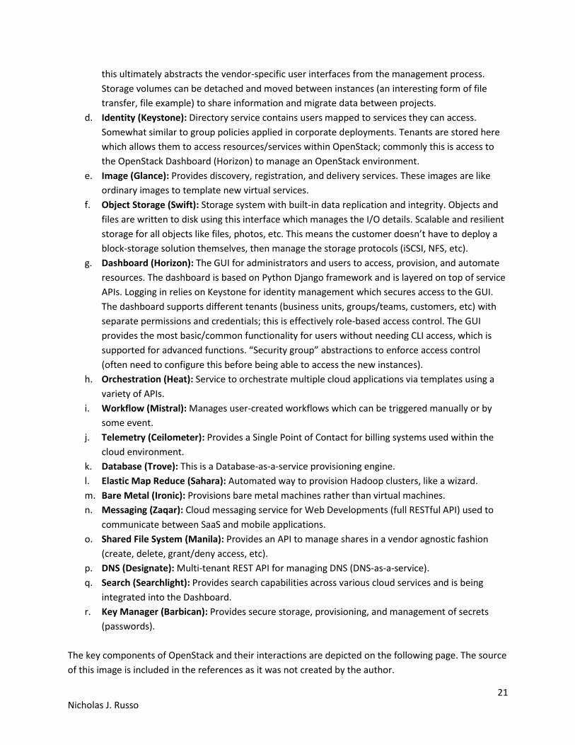
b. Augmented: This model relies on a fully distributed control-plane by adding a centralized
controller that can apply policy to parts of the network at will. Such a controller could inject
shorter-match IP prefixes, policy-based routing (PBR), security features (ACL), or other policy
objects. This model is a good compromise between distributing intelligence between nodes to
prevent singles points of failure (which a controller introduces) by using a known-good
distributed control-plane underneath. The policy injection only happens when it “needs to”,
such as offloading an overloaded link in a DC fabric or from a long-haul fiber link between two
points of presence (POPs) in an SP core. Cisco’s Performance Routing (PfR) is an example of the
augment model. Another example includes offline path computation element (PCE) servers for
automated MPLS TE tunnel creation. In both cases, a small set of routers (PfR border routers or
TE tunnel head-ends) are modified, yet the remaining routers are untouched. This model has a
lower impact on the existing network because the wholesale failure of the controller simply
returns the network to the distributed model, which is known to work “well enough” in many
cases. The augmented model is depicted on the following page.
24 Nicholas J. Russo
PFR MC PUSHES
POLICY TO EDGE
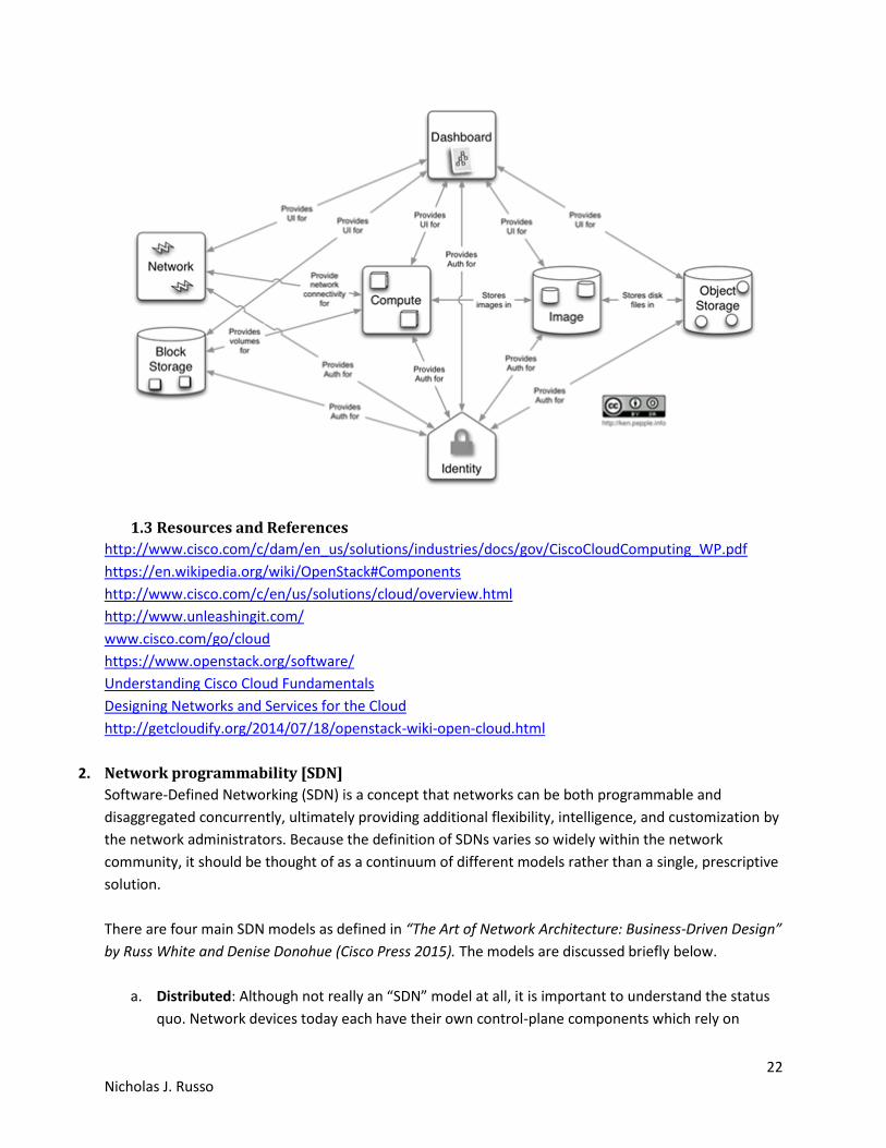
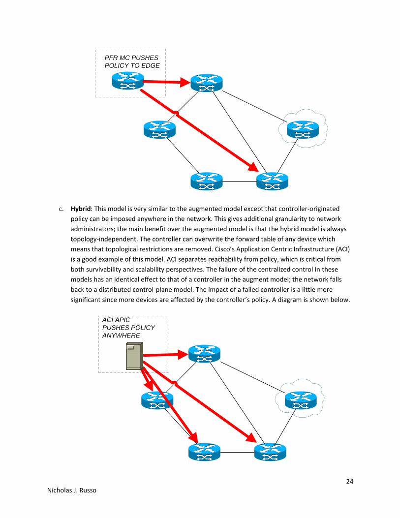
c. Hybrid: This model is very similar to the augmented model except that controller-originated
policy can be imposed anywhere in the network. This gives additional granularity to network
administrators; the main benefit over the augmented model is that the hybrid model is always
topology-independent. The controller can overwrite the forward table of any device which
means that topological restrictions are removed. Cisco’s Application Centric Infrastructure (ACI)
is a good example of this model. ACI separates reachability from policy, which is critical from
both survivability and scalability perspectives. The failure of the centralized control in these
models has an identical effect to that of a controller in the augment model; the network falls
back to a distributed control-plane model. The impact of a failed controller is a little more
significant since more devices are affected by the controller’s policy. A diagram is shown below.
ACI APIC
PUSHES POLICY
ANYWHERE
25 Nicholas J. Russo
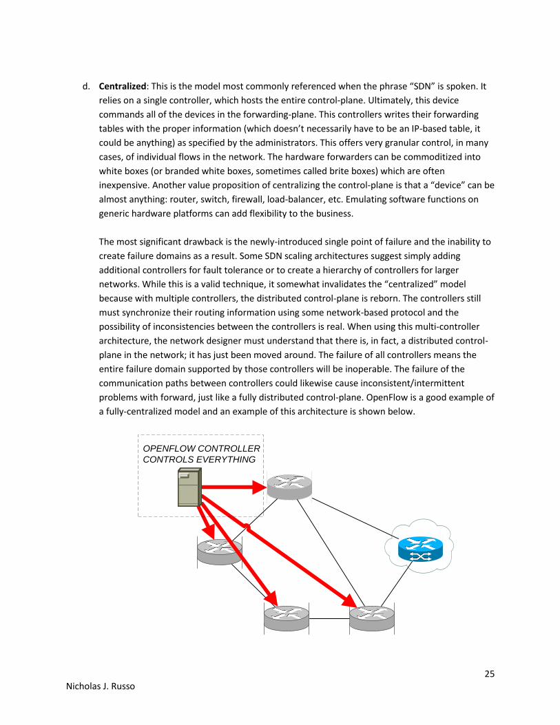
d. Centralized: This is the model most commonly referenced when the phrase “SDN” is spoken. It
relies on a single controller, which hosts the entire control-plane. Ultimately, this device
commands all of the devices in the forwarding-plane. This controllers writes their forwarding
tables with the proper information (which doesn’t necessarily have to be an IP-based table, it
could be anything) as specified by the administrators. This offers very granular control, in many
cases, of individual flows in the network. The hardware forwarders can be commoditized into
white boxes (or branded white boxes, sometimes called brite boxes) which are often
inexpensive. Another value proposition of centralizing the control-plane is that a “device” can be
almost anything: router, switch, firewall, load-balancer, etc. Emulating software functions on
generic hardware platforms can add flexibility to the business.
The most significant drawback is the newly-introduced single point of failure and the inability to
create failure domains as a result. Some SDN scaling architectures suggest simply adding
additional controllers for fault tolerance or to create a hierarchy of controllers for larger
networks. While this is a valid technique, it somewhat invalidates the “centralized” model
because with multiple controllers, the distributed control-plane is reborn. The controllers still
must synchronize their routing information using some network-based protocol and the
possibility of inconsistencies between the controllers is real. When using this multi-controller
architecture, the network designer must understand that there is, in fact, a distributed control-
plane in the network; it has just been moved around. The failure of all controllers means the
entire failure domain supported by those controllers will be inoperable. The failure of the
communication paths between controllers could likewise cause inconsistent/intermittent
problems with forward, just like a fully distributed control-plane. OpenFlow is a good example of
a fully-centralized model and an example of this architecture is shown below.
OPENFLOW CONTROLLER
CONTROLS EVERYTHING
26 Nicholas J. Russo
2.1 Describe functional elements of network programmability (SDN) and how they
interact
2.1.1 Controllers
As discussed briefly above, “controllers” are components that are responsible for programming
forwarding tables of data-plane device. Controllers themselves could even be routers, like Cisco’s PfR
operating as a master controller (MC), or they could be software-only appliances, as seen with
OpenFlow networks or Cisco’s Application Policy Infrastructure Controller (APIC) used with ACI. The
models discussed above help detail the significance of the controller; this is entirely dependent on the
deployment model. The more involved a controller is, the more flexibility the network administrator
gains. This must be weighed against the increased reliance on the controller itself.
2.1.2 APIs
An Application Program Interface (API) is meant to define a standard way of interfacing with a software
application or operating system. It may consistent of functions (methods, routines, etc), protocols,
system call constructors, and other “hooks” for integration. Both the controllers and business
applications would need the appropriate APIs revealed for integration between the two. This makes up
the northbound communication path as discussed in section 2.1.5. By creating a common API for
communications between controllers and business applications, either one can be changed at any time
without significantly impacting the overall architecture.
A common API that is discussed within the networking world is Representational State Transfer (REST).
REST represents an “architectural style” of transferring information between clients and servers. In
essence, it is a way of defining attributes or characteristics of how data is moved. REST is commonly
used with HTTP by combining traditional HTTP methods (GET, POST, PUT, DELETE, etc) and Universal
Resource Identifiers (URI). The end result is that API requests look like URIs and are used to fetch/write
specific pieces of data to a target machine. This simplification helps promote automation, especially for
web-based applications or services. Note that HTTP is stateless which means the server does not store
session information for individual flows; REST API calls retain this stateless functionality as well. This
allows for seamless REST operation across HTTP proxies and gateways.
2.1.3 Scripting
Scripting is a fundamental topic of an effective automation design. Scripting can allow network
administrators to define the policy constraints for a given application in a manner than is consistent and
clear. Other operators can “fork” this script (copy it and start a new version from a common point) and
potentially “merge” the changes back in later. This is how advanced policies can be defined in an SDN-
based architecture. The scripts can be manually applied as discussed earlier with the VLAN-creation
example, or they could be assembled in sequence by an orchestrator as part of a larger workflow or
process. In any case, an administrator needs to write the script in the first place, and like all pieces of
code, it must be maintained, tested, versioned, and continuously monitored. A popular repository for
text file configuration management is Github or BitBucket, while popular scripting languages include
Python, Ruby, JavaScript, and Perl. Neither of these are complete lists.
27 Nicholas J. Russo
2.1.4 Agents
Management agents are typically on-box software components that allow an infrastructure device to
report traffic conditions back to the controller. This information flows upstream through the
southbound interface discussed in section 2.1.5 and is primarily used to “complete” the controller’s view
of the network. Given this information, the controller can sense congestion, route around failures, and
perform all manner of fancy traffic-engineering as required by the business applications. Many of these
agents perform the same general function as SNMP yet offer increased flexibility and granularity as they
are programmable.
Agents could also be used for non-management purposes, at least from a general view. Interface to the
Routing System (I2RS) is an SDN technique where a specific control-plane agent is required on every
data-plane forwarder. This agent is effectively the control-plane client that communicates upstream
towards the controller. This is the channel by which the controller consults its RIB and populates the FIB
of the forwarding devices. The same is true for OpenFlow (OF) which is a fully centralized SDN model.
The agent can be considered an interface to a data-plane forwarder for a control-plane SDN controller.
A simple categorization method is to quantify management strategies as “agent based” or “agent-less
based”. Agent is pull-based, which means the agent connects with master. Changes made on master are
pulled down when agent is “ready”. This can be significant since if a network device is currently
tolerating a microburst, the management agent can wait until the contention abates before passing
telemetry data to the master. Agent-less is push-based like SNMP traps, where the triggering of an event
on a network device creates a message for the controller in unsolicited fashion. The other direction also
true; a master can use SSH to access a device for programming whenever the master is “ready”.
Although not specific to “agents”, there are several common applications/frameworks that are used for
device management. Some of them rely on agents while others do not. Three of them are discussed
briefly below as these are found in Cisco’s “NX-OS DevNet Network Automation Guide”. Note that
subsets of the exact definitions are added here. Since these are third-party products, the author does
not want to misrepresent the facts or capabilities as understood by Cisco.
a. Puppet (by Puppet Labs): The Puppet software package is an open source automation toolset
for managing servers and other resources by enforcing device states, such as configuration
settings. Puppet components include a puppet agent which runs on the managed device (client)
and a puppet master (server) that typically runs on a separate dedicated server and serves
multiple devices. The Puppet master compiles and sends a configuration manifest to the agent.
The agent reconciles this manifest with the current state of the node and updates state based on
differences. A puppet manifest is a collection of property definitions for setting the state on the
device. Manifests are commonly used for defining configuration settings, but they can also be
used to install software packages, copy files, and start services.
In summary, Puppet is agent-based (requiring software installed on the client) and pushes
complex data structures to managed nodes from the master server. Puppet manifests are used
as data structures to track node state and display this state to the network operators.
28 Nicholas J. Russo
b. Chef (by Chef Software): Chef is a systems and cloud infrastructure automation framework that
deploys servers and applications to any physical, virtual, or cloud location, no matter the size of
the infrastructure. Each organization is comprised of one or more workstations, a single server,
and every node that will be configured and maintained by the chef-client. A cookbook defines a
scenario and contains everything that is required to support that scenario, including libraries,
recipes, files, and more. A Chef recipe is a collection of property definitions for setting state on
the device. While recipes are commonly used for defining configuration settings, they can also be
used to install software packages, copy files, start services, and more.
In summary, Chef is very similar to Puppet in that it requires agents and manages devices using
complex data structures. The concepts of cookbooks and recipes are specific to Chef (hence the
name) which contribute to a hierarchical data structure management system. A Chef cookbook
is loosely equivalent to a Puppet manifest.
c. Ansible (by Red Hat): Ansible is an open source IT configuration management and automation
tool. Unlike Puppet and Chef, Ansible is agent-less, and does not require a software agent to be
installed on the target node (server or switch) in order to automate the device. By default,
Ansible requires SSH and Python support on the target node, but Ansible can also be easily
extended to use any API.
In summary, Ansible is somewhat lighter-weight than Puppet or Chef given that management is
agent-less. No custom software needs to be installed on any device provided that it supports
SSH. This can be a drawback since individual device CLIs must be exposed to network operators
(or, at best, the Ansible automation engine) instead of using a more abstract API design.
2.1.5 Northbound vs. Southbound protocols
Controllers sit “in the middle” of the SDN notional architecture. It uses northbound and southbound
communication paths to operate with other components of the architecture.
The northbound interfaces are considered APIs which are interfaces to existing business applications.
This is generally used so that applications can make requests of the network, which could include
specific performance requirements (bandwidth, latency, etc). Because the controller “knows” this
information by communicating with the infrastructure devices via management agents, it can determine
the best paths through the network to satisfy these constraints. This is loosely analogous to the original
intent of the Integrated Services QoS model using Resource Reservation Protocol (RSVP) where
applications would reserve bandwidth on a per-flow basis. It is also similar to MPLS TE constrained SPF
(CSPF) where a single device can source-route traffic through the network given a set of requirements.
The logic is being extended to applications with a controller “shim” in between, ultimately providing a
full network view for optimal routing. A REST API is an example of a northbound interface.

29 Nicholas J. Russo
The southbound interfaces include the control-plane protocol between the centralized controller and
the network forwarding hardware. These are the less intelligent network devices used for forwarding
only (assuming a centralized model). A common control-plane used for this purpose would be
OpenFlow; the controller determines the forwarding tables per flow per network device, programs this
information, and then the devices obey it. Note that OpenFlow is not synonymous with SDN; it is just an
example of one southbound control-plane protocol. Because the SDN controller is sandwiched between
the northbound and southbound interfaces, it can be considered “middleware” in a sense. The
controller is effectively able to evaluate application constraints and produce forwarding-table outputs.
The image below depicts a very high-level diagram of the SDN layers as it relates to interaction between
components.
2.2 Describe aspects of virtualization and automation in network environments
Network virtualization is often misunderstood as being something as simple as “virtualize this server
using a hypervisor and extend some VLANs to the host”. Network virtualization is really referring to the
creation of virtual topologies using a variety of technologies to achieve a given business goal. Sometimes
these virtual topologies are overlays, sometimes they are forms of multiplexing, and sometimes they are
a combination of the two. Here are some common examples (not a complete list) of network
virtualization using well-known technologies.
a. Ethernet VLANs using 802.1q encapsulation. Often used to create virtual networks at layer 2 for
security segmentation, traffic hair pinning through a service chain, etc. This is a form of data
multiplexing over Ethernet links. It isn’t a tunnel/overlay since the layer 2 reachability
information (MAC address) remains exposed and used for forwarding decisions.

30 Nicholas J. Russo
b. VPN Routing and Forwarding (VRF) tables or other layer-3 virtualization techniques. Similar
uses as VLANs except virtualizes an entire routing instance, and is often used to solve a similar
set of problems. Can be combined with VLANs to provide a complete virtual network between
layers 2 and 3. Can be coupled with GRE for longer-range virtualization solutions over a core
network that may or may not have any kind of virtualization. This is a multiplexing technique as
well but is control-plane only since there is no change to the packets on the wire, nor is there
any inherent encapsulation (not an overlay).
c. Frame Relay DLCI encapsulation. Like a VLAN, creates segmentation at layer 2 which might be
useful for last-mile access circuits between PE and CE for service multiplexing. The same is true
for Ethernet VLANs when using EV services such as EV-LINE, EV-LAN, and EV-TREE. This is a data-
plane multiplexing technique specific to frame relay.
d. MPLS VPNs. Different VPN customers, whether at layer 2 or layer 3, are kept completely
isolated by being placed in a different virtual overlay across a common core that has no/little
native virtualization. This is an example of an overlay type of virtual network.
e. VXLAN. Just like MPLS VPNs; creates virtual overlays atop a potentially non-virtualized core.
Doesn’t provide a native control-plane, but that doesn’t matter; it’s still a virtualization
technique. Could be paired with BGP EVPN if MAC routing is desired. This is another example of
an overlay type of virtual network.
f. OTV. Just like MPLS VPNs; creates virtual overlays atop a potentially non-virtualized core, except
provides a control-plane for MAC routing. IP multicast traffic is also routed intelligently using
GRE encapsulation with multicast destination addresses. This is another example of an overlay
type of virtual network.
2.2.1 DevOps methodologies, tools and workflows
The term “DevOps” is relatively new and is meant to describe not just a job title but a cultural shift in
service delivery, management, and operation. It was formerly known as “agile system administration” or
“agile methodology”. The keyword “agile” typically refers to the integration of development and
operations staff throughout the entire lifecycle of a service. The idea is to tear down the silos and the
resulting poor service delivery that both teams facilitate. Often times, developers will create
applications without understanding the constraints of the network, while the network team will create a
network (ineffective QoS, slow rerouting, etc) policies that don’t support the business-critical
applications.
The tools and workflows used within the DevOps community are things that support an information
sharing environment. Many of them are focused on version control, service monitoring, configuration
management, orchestration, containerization, and everything else needed to typically support a service
through its lifecycle. The key to DevOps is that using a specific DevOps “tool” does not mean an
organization has embraced the DevOps culture or mentality. A good phrase is “People over Process over
Tools”, as the importance of a successful DevOps team is reliance on those things, in that order.
DevOps also introduces several new concepts. Two critical ones are continuous integration (CI) and
continuous delivery (CD). The CI/CD mindset suggests several changes to traditional SW development.
Some of the key points are listed below.
31 Nicholas J. Russo
a. Everyone can see the changes: Dev, Ops, Quality Assurance (QA), management, etc
b. Verification is an exact clone of the production environment, not simply a smoke-test on a
developer’s test bed
c. The build and deployment/upgrade process is automated
d. Provide SW in short timeframes and ensure releases are always available in increments
e. Reduce friction, increase velocity
f. Reduce silos, increase collaboration
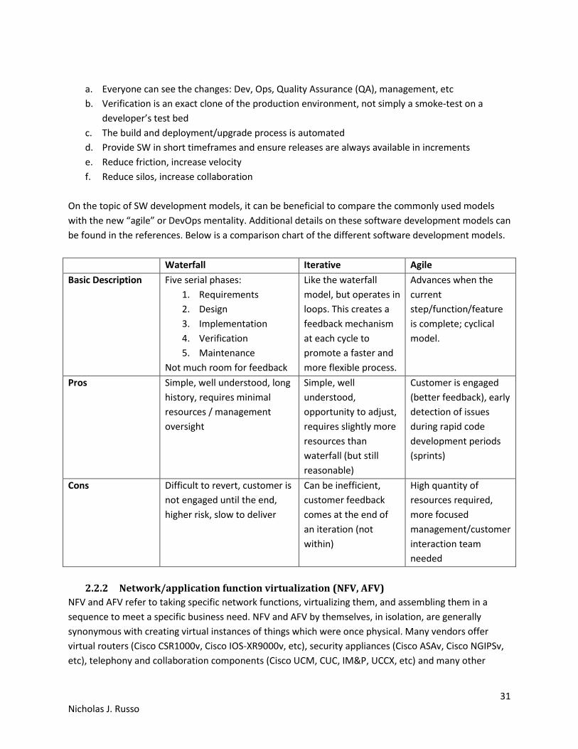
On the topic of SW development models, it can be beneficial to compare the commonly used models
with the new “agile” or DevOps mentality. Additional details on these software development models can
be found in the references. Below is a comparison chart of the different software development models.
Waterfall Iterative Agile
Basic Description Five serial phases:
1. Requirements
2. Design
3. Implementation
4. Verification
5. Maintenance
Not much room for feedback
Like the waterfall
model, but operates in
loops. This creates a
feedback mechanism
at each cycle to
promote a faster and
more flexible process.
Advances when the
current
step/function/feature
is complete; cyclical
model.
Pros Simple, well understood, long
history, requires minimal
resources / management
oversight
Simple, well
understood,
opportunity to adjust,
requires slightly more
resources than
waterfall (but still
reasonable)
Customer is engaged
(better feedback), early
detection of issues
during rapid code
development periods
(sprints)
Cons Difficult to revert, customer is
not engaged until the end,
higher risk, slow to deliver
Can be inefficient,
customer feedback
comes at the end of
an iteration (not
within)
High quantity of
resources required,
more focused
management/customer
interaction team
needed
2.2.2 Network/application function virtualization (NFV, AFV)
NFV and AFV refer to taking specific network functions, virtualizing them, and assembling them in a
sequence to meet a specific business need. NFV and AFV by themselves, in isolation, are generally
synonymous with creating virtual instances of things which were once physical. Many vendors offer
virtual routers (Cisco CSR1000v, Cisco IOS-XR9000v, etc), security appliances (Cisco ASAv, Cisco NGIPSv,
etc), telephony and collaboration components (Cisco UCM, CUC, IM&P, UCCX, etc) and many other

32 Nicholas J. Russo
things that were once physical appliances. Separating these things into virtual functions allows a wide
variety of organizations, from cloud providers to small enterprises, to select only the components they
require. The following chapter describes a commonly used and powerful NFV/AFV use case.
2.2.3 Service function chaining
As mentioned briefly above, service chaining is taking NFV/AFV components and sequencing them to
create some customized “chain of events” to solve a business problem. NFV/AFV by itself isn’t terribly
useful if specific services cannot be easily linked in a meaningful way. Service chaining, especially in
cloud environments, can be achieved in a variety of technical ways. For example, one organization may
require routing and firewall, while another may require routing and intrusion prevention. The per-
customer granularity is a powerful offering of service chaining in general. The main takeaway is that all
of these solutions are network virtualization solutions of sorts.
a. MPLS and Segment Routing. Some headend LSR needs to impose different MPLS labels for each
service in the chain that must be visited to provide a given service. MPLS is a natural choice here
given the label stacking capabilities and theoretically-unlimited label stack depth.
b. Networking Services Header (NSH). Similar to the MPLS option except is purpose-built for
service chaining. Being purpose-built, NSH can be extended or modified in the future to better
support new service chaining requirements, where doing so with MPLS shim header formats is
less likely. MPLS would need additional headers or other ways to carry “more” information.
c. Out of band centralized forwarding. Although it seems unmanageable, a centralized controller
could simply instruct the data-plane devices to forward certain traffic through the proper
services without any in-band encapsulation being added to the flow. This would result in an
explosion of core state which could limit scalability, similar to policy-based routing at each hop.
d. Cisco vPath: This is a Cisco innovation that is included with the Cisco Nexus 1000v series switch
for use as a distributed virtual switch (DVS) in virtualized server environments. Each service is
known as a virtual service node (VSN) and the administrator can select the sequence in which
each node should be transited in the forwarding path. Traffic transiting the Nexus 1000v switch
is subject to redirection using some kind of overlay/encapsulation technology. Specifically, MAC-
in-MAC encapsulation is used for layer-2 tunnels while MAC-in-UDP is used for layer-4 tunnels.
2.2.4 Performance, availability, and scaling considerations
There are many trade-offs between the different SDN models. The following page includes a table that
attempts to capture the most important ones.
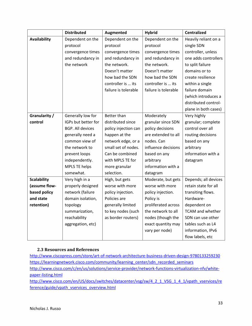
33 Nicholas J. Russo
Distributed Augmented Hybrid Centralized
Availability Dependent on the
protocol
convergence times
and redundancy in
the network
Dependent on the
protocol
convergence times
and redundancy in
the network.
Doesn’t matter
how bad the SDN
controller is … its
failure is tolerable
Dependent on the
protocol
convergence times
and redundancy in
the network.
Doesn’t matter
how bad the SDN
controller is … its
failure is tolerable
Heavily reliant on a
single SDN
controller, unless
one adds controllers
to split failure
domains or to
create resilience
within a single
failure domain
(which introduces a
distributed control-
plane in both cases)
Granularity /
control
Generally low for
IGPs but better for
BGP. All devices
generally need a
common view of
the network to
prevent loops
independently.
MPLS TE helps
somewhat.
Better than
distributed since
policy injection can
happen at the
network edge, or a
small set of nodes.
Can be combined
with MPLS TE for
more granular
selection.
Moderately
granular since SDN
policy decisions
are extended to all
nodes. Can
influence decisions
based on any
arbitrary
information with a
datagram
Very highly
granular; complete
control over all
routing decisions
based on any
arbitrary
information with a
datagram
Scalability
(assume flow-
based policy
and state
retention)
Very high in a
properly designed
network (failure
domain isolation,
topology
summarization,
reachability
aggregation, etc)
High, but gets
worse with more
policy injection.
Policies are
generally limited
to key nodes (such
as border routers)
Moderate, but gets
worse with more
policy injection.
Policy is
proliferated across
the network to all
nodes (though the
exact quantity may
vary per node)
Depends; all devices
retain state for all
transiting flows.
Hardware-
dependent on
TCAM and whether
SDN can use other
tables such as L4
information, IPv6
flow labels, etc
2.3 Resources and References
http://www.ciscopress.com/store/art-of-network-architecture-business-driven-design-9780133259230
https://learningnetwork.cisco.com/community/learning_center/sdn_recorded_seminars
http://www.cisco.com/c/en/us/solutions/service-provider/network-functions-virtualization-nfv/white-
paper-listing.html
http://www.cisco.com/en/US/docs/switches/datacenter/vsg/sw/4_2_1_VSG_1_4_1/vpath_vservices/re
ference/guide/vpath_vservices_overview.html

34 Nicholas J. Russo
https://developer.cisco.com/site/devnet/home/index.gsp
www.cisco.com/go/sdn
BRKNMS-2446 - Do IT with DevOps (2015 San Diego)
BRKDEV-2001 - DevOps in Programmable Network Environments (2015 San Diego)
BRKCRT-2603 - Cloudy with a chance of SDN (2015 San Diego)
BRKSDN-2761 - OpenDaylight: The Open Source SDN Controller Platform (2015 San Diego)
BRKSDN-1903 - A Model-driven Approach to Software Defined Networks with Yang, Netconf/Restconf
(2015 San Diego)
BRKRST-1014: Introduction to Software-Defined Networking (SDN) and Network Programmability (2015
San Diego)
Cisco - Introducing Network Programmability Fundamentals
Cisco - Introduction to APIC EM Deployment
Introduction to SDN (LiveLesson)
ETSI NFV Whitepaper
NX-OS DevNet Network Automation Guide
RFC6241 - NETCONF
RFC6020 - YANG
3. Internet of Things (IoT)
IoT, sometimes called Internet of Everything (IoE), is a concept that many non-person entities (NPEs) or
formerly non-networked devices in the world would suddenly be networked. This typically includes
things like window blinds, light bulbs, water treatment plant sensors, home heating/cooling units, street
lights, and anything else that could be remotely controlled or monitored. The business drivers for IoT are
substantial: electrical devices (like lights and heaters) could consume less energy by being smartly
adjusted based on changing conditions, window blinds can open and close based on the luminosity of a
room, and chemical levels can be adjusted in a water treatment plant by networked sensors. These are
all real-life applications of IoT and network automation in general.
The term Low-power and Lossy Networks (LLN) is commonly used in the IoT space since it describes the
vast majority of IoT networks. LLNs have the following basic characteristics (incomplete list):
a. Bandwidth constraints
b. Highly unreliable
c. Limited resources (power, CPU, and memory)
d. Extremely high scale (hundreds of millions and possibly more)
3.1 Describe architectural framework and deployment considerations
IoT combines a number of emerging technologies into its generalized network architecture. The
architecture consists primarily of four layers:
a. Data center (DC) Cloud: Although not a strict requirement, the understanding that a public
cloud infrastructure exists to support IoT is a common one. A light bulb manufacturer could

35 Nicholas J. Russo
partner with a networking vendor to develop network-addressable light bulbs which are
managed from a custom application running in the public cloud. This might be better than a
private cloud solution since, if the application is distributed, regionalized instances could be
deployed in geographically dispersed areas using an “anycast” design for scalability and
performance improvements. As such, public cloud is generally assumed to be the DC presence
for IoT networks.
b. Core Networking and Services: This could be a number of transports to connect the public cloud
to the sensors. The same is true for any connection to public cloud, in reality, since even
businesses need to consider the manner in which they connect to public cloud. The primary
three options (private WAN, IXP, or Internet VPN) were discussed in the Cloud section. The same
options apply here. A common set of technologies/services seen within this layer include IP,
MPLS, mobile packet core, QoS, multicast, security, network services, hosted cloud applications,
big data, and centralized device management (such as a network operations facility).
c. Multi-service Edge (access network): Like most SP networks, the access technologies tend to
vary greatly based on geography, cost, and other factors. Access networks can be optically-
based to provide Ethernet handoffs to IoT devices; this would make sense for relatively large
devices that would have Ethernet ports and would be generally immobile. Mobile devices, or
those that are small or remote, might use cellular technologies such as 2G, 3G, or 4G/LTE for
wireless backhaul to the closest POP. A combination of the two could be used by extending
Ethernet to a site and using 802.11 WIFI to connect the sensors to the WLAN. The edge network
may require use of “gateways” as a short-term solution for bridging (potentially non-IP) IoT
networks into traditional IP networks. The gateways come with an associated high CAPEX and
OPEX since they are custom devices to solve a very specific use-case. Specifically, gateways are
designed to perform some subset of the following functions, according to Cisco:
I. Map semantics between two heterogeneous domains: The word semantics in this
context refers to the way in which two separate networks operate and how each
network interprets things. If the embedded systems network is a transparent radio
mesh using a non-standard set of protocols while the multi-service edge uses IP over
cellular, the gateway is responsible for “presenting” common interfaces to both
networks. This allows devices in both networks to communicate using a “language” that
is common to each.
II. Perform translation in terms of routing, QoS security, management, etc: These items are
some concrete examples of semantics. An appropriate analogy for IP networkers is
stateless NAT64; an inside-local IPv4 host must send traffic to some outside-local IPv4
address which represents an outside-global IPv6 address. The source of that packet
becomes an IPv6 inside-global address so that the IPv6 destination can properly reply.
III. Do more than just protocol changes: The gateways serve as interworking devices
between architectures at an architectural level. The gateways might have a mechanism
for presenting network status/health between layers, and more importantly, be able to

36 Nicholas J. Russo
fulfill their architectural role in ensuring end-to-end connectivity across disparate
network types.
Embedded Systems (Smart Things Network): This layer represents the host devices themselves.
They can be wired or wireless, smart or less smart, or any other classification that is useful to
categorize an IoT component. Often times, such devices support zero-touch provisioning (ZTP)
which helps with the initial deployment of massive-scale IoT deployments. For static
components, these components are literally embedded in the infrastructure and should be
introduced during the construction of a building, factory, hospital, etc. These networks are
rather stochastic (meaning that behavior can be unpredictable). The author classifies wireless
devices into three general categories which help explain what kind of RF-level transmission
methods are most sensible:
I. Long range: Some devices may be placed very far from their RF base stations/access
points and could potentially be highly mobile. Smart automobiles are a good example of
this; such devices are often equipped with cellular radios, such as 4G/LTE. Such an
option is not optimal for supporting LLNs given the cost of radios and power required to
run them. To operate a private cellular network, the RF bands must be licensed (in the
USA, at least), which creates an expensive and difficult barrier for entry.
II. Short range with “better” performance: Devices that are within a local area, such as a
building, floor of a large building, or courtyard area, could potentially use unlicensed
frequency bands while transmitting at low power. These devices could be CCTV sensors,
user devices (phones, tablets, laptops, etc), and other general-purpose things whereby
maximum battery life and cost savings are eclipsed by the need for superior
performance. IEEE 802.11 WIFI is commonly used in such environments. IEEE 802.16
WIMAX specifications could also be used, but in the author’s experience, it is rare.
III. Short range with “worse” performance: Many IoT devices fall into this final category
whereby the device itself has a very small set of tasks it must perform, such as sending a
small burst of data when an event occurs (i.e., some nondescript sensor). Devices are
expected to be installed one time, rarely maintained, procured/operated at low cost,
and be value-engineered to do very few things. These devices are less commonly
deployed in home environments since many homes have WIFI; they are more commonly
seen spread across cities. Examples might include street lights, sprinklers, and
parking/ticketing meters. IEEE has defined 802.15.4 to support low-rate wireless
personal area networks (LR-PANS) which is used for many such IoT devices. Note that
802.15.4 is the foundation for upper-layer protocols such as ZigBee and WirelessHART.
ZigBee, for example, is becoming popular in homes to network some IoT devices, such
as thermostats, which may not support WIFI in their hardware.
IEEE 802.15.4 is worth a brief discussion by itself. Unlike WIFI, all nodes are “full-function” and can act as
both hosts and routers; this is typical for mesh technologies. A device called a PAN coordinator is
analogous to a WIFI access point (WAP) which connects the PAN to the wired infrastructure; this
technically qualities the PAN coordinator as a “gateway” discussed earlier.
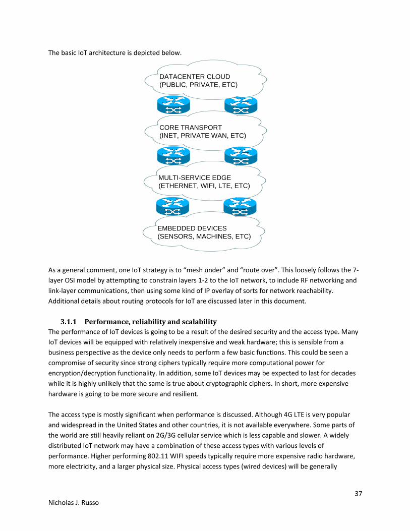
37 Nicholas J. Russo
The basic IoT architecture is depicted below.
DATACENTER CLOUD
(PUBLIC, PRIVATE, ETC)
CORE TRANSPORT
(INET, PRIVATE WAN, ETC)
MULTI-SERVICE EDGE
(ETHERNET, WIFI, LTE, ETC)
EMBEDDED DEVICES
(SENSORS, MACHINES, ETC)
As a general comment, one IoT strategy is to “mesh under” and “route over”. This loosely follows the 7-
layer OSI model by attempting to constrain layers 1-2 to the IoT network, to include RF networking and
link-layer communications, then using some kind of IP overlay of sorts for network reachability.
Additional details about routing protocols for IoT are discussed later in this document.
3.1.1 Performance, reliability and scalability
The performance of IoT devices is going to be a result of the desired security and the access type. Many
IoT devices will be equipped with relatively inexpensive and weak hardware; this is sensible from a
business perspective as the device only needs to perform a few basic functions. This could be seen a
compromise of security since strong ciphers typically require more computational power for
encryption/decryption functionality. In addition, some IoT devices may be expected to last for decades
while it is highly unlikely that the same is true about cryptographic ciphers. In short, more expensive
hardware is going to be more secure and resilient.
The access type is mostly significant when performance is discussed. Although 4G LTE is very popular
and widespread in the United States and other countries, it is not available everywhere. Some parts of
the world are still heavily reliant on 2G/3G cellular service which is less capable and slower. A widely
distributed IoT network may have a combination of these access types with various levels of
performance. Higher performing 802.11 WIFI speeds typically require more expensive radio hardware,
more electricity, and a larger physical size. Physical access types (wired devices) will be generally

38 Nicholas J. Russo
immobilized which could be considered a detriment to physical performance, if mobility is required for
an IoT device to do its job effectively.
3.1.2 Mobility
The mobility of an IoT device is going to be largely determined by its access method. Devices that are on
802.11 WIFI within a factory will likely have mobility through the entire factory, or possibly the entire
complex, but will not be able to travel large geographic distances. For some specific manufacturing work
carts (containing tools, diagnostic measurement machines, etc), this might be an appropriate method.
Devices connected via 4G LTE will have greater mobility but will likely represent something that isn’t
supposed to be constrained to the factory, such as a service truck or van. Heavy machinery bolted to the
factory floor might be wired since it is immobile.
3.1.3 Security and privacy
Providing security and private for IoT devices is challenging mostly due to the sheer expanse of the
access network and supported clients (IoT devices). Similar concepts still apply as they would for normal
hosts except for needing to work in a massively scalable and distributed network:
a. Use IEEE 802.1x for wired and wireless authentication for all devices. This is normally tied into a
Network Access Control (NAC) architecture which authorizes a set of permissions per device.
b. Encrypt wired and wireless traffic using MACsec/IPsec as appropriate.
c. Maintain physical accounting of all devices, especially small ones, to prevent theft and reverse
engineering.
d. Do not allow unauthorized access to sensors; ensure remote locations are secure also.
e. Provide malware protection for sensors so that the compromise of a single sensor is detected
quickly and suppressed.
f. Rely on cloud-based threat analysis (again, assumes cloud is used) rather than a distributed
model given the size of the IoT access network and device footprint. Sometimes this extension
of the cloud is called the “fog” and encompasses other things that product and act on IOT data.
Another discussion point on the topic of security is determining how/where to “connect” an IoT
network. This is going to be determined based on the business need, as always, but the general logic is
similar to what traditional corporate WANs use:
a. Fully private connections: Some IoT networks have no legitimate need to be accessible via the
public Internet. Such examples would include Government sensor networks which may be
deployed in a battlefield support capacity. More common examples might include Cisco’s
“Smart Grid” architecture which is used for electricity distribution and management within a
city. Exposing such a critical resource to a highly insecure network offers little value since the
public works department can likely control it from a dedicated NOC. System updates can be
performed in-house and the existence of the IoT network can be (and often times, should be)
largely unknown by the general population. In general, IoT networks that fall into this category
are “producer-oriented” networks.

39 Nicholas J. Russo
b. Public Internet: Other IoT networks are designed to have their information shared or made
public between users. One example might be a managed thermostat service; users can log into a
web portal hosted by the service provider to check their home heating/cooling statistics, make
changes, pay bills, request refunds, submit service tickets, and the like. Other networks might be
specifically targeted to sharing information publicly, such as fitness watches that track how long
an individual exercises. The information could be posted publicly and linked to one’s social
media page so others can see it. A more practical and useful example could include public safety
information via a web portal hosted by the Government. In general, IoT networks that fall into
this category are “consumed-oriented” networks.
3.1.4 Standards and compliance
Controlling access and identifying areas of responsibility can be challenging with IoT. Cisco provides the
following example: For example, Smart Traffic Lights where there are several interested parties such as
Emergency Services (User), Municipality (owner), Manufacturer (Vendor). Who has provisioning access?
Who accepts Liability?
There is more than meets the eye with respect to standards and compliance for street lights. Most
municipalities (such as counties or townships within the United States) have ordinances that dictate how
street lighting works. The light must be a certain color, must not “trespass” into adjacent streets, must
not negatively affect homeowners on that street, etc. This complicates the question above because the
lines become blurred between organizations rather quickly. In cases like this, the discussions must occur
between all stakeholders, generally chaired by a Government/company representative (depending on
the consumer/customer), to draw clear boundaries between responsibilities.
Radio frequency (RF) spectrum is a critical point as well. While WIFI can operate in the 2.4 GHz and 5.0
GHz bands without a license, there are no unlicensed 4G LTE bands at the time of this writing. Deploying
4G LTE capable devices on an existing carrier’s network within a developed country may not be a
problem. Doing so in developing or undeveloped countries, especially if 4G LTE spectrum is tightly
regulated but poorly accessible, can be a challenge.
Several new protocols have been introduced specifically for IoT, some of which are standardized:
a. RPL - IPv6 Routing Protocol for LLNs (RFC 6550): RPL is a distance-vector routing protocol
specifically designed to support IoT. At a high-level, RPL is a combination of control-plane and
forwarding logic of three other technologies: regular IP routing, multi-topology routing (MTR),
and MPLS traffic-engineering (MPLS TE). RPL is similar to regular IP routing in that directed
acyclic graphs (DAG) are created through the network. This is a fancy way of saying “loop-free
shortest path” between two points. These DAGs can be “colored” into different topologies
which represent different network characteristics, such as high bandwidth or low latency. This
forwarding paradigm is similar to MTR in concept. Last, traffic can be assigned to a colored DAG
based on administratively-defined constraints, including node state, node energy, hop count,

40 Nicholas J. Russo
throughput, latency, reliability, and color (administrative preference). This is similar to MPLS
TE’s constrained shortest path first (CSPF) process which is used for defining administrator-
defined paths through a network based on a set of constraints, which might have technical
and/or business drivers behind them.
b. 6LoWPAN - IPv6 over Low Power WPANs (RFC 4919): This technology was specifically
developed to be an adaptation layer for IPv6 for IEEE 802.15.4 wireless networks. Specifically, it
“adapts” IPv6 to work over LLNs which encompasses many functions:
I. MTU correction: The minimum MTU for IPv6 across a link, as defined in RFC2460, is
1280 bytes. The maximum MTU for IEEE 802.15.4 networks is 127 bytes. Clearly, no
value can mathematically satisfy both conditions concurrently. 6LoWPAN performs
fragmentation and reassembly by breaking the large IPv6 packets into IEEE 802.15.4
frames for transmission across the wireless network.
II. Header compression: Many compression techniques are stateful and CPU-hungry. This
strategy would not be appropriate for low-cost LLNs, so 6LoWPAN utilizes an algorithmic
(stateless) mechanism. RFC4944 defines some common assumptions:
i. The version is always IPv6.
ii. Both source and destination addresses are link-local.
iii. The low-order 64-bits of the link-local addresses can be derived from the layer-2
network addressing in an IEEE 802.15.4 wireless network.
iv. The packet length can be derived from the layer-2 header.
v. Next header is always ICMP, TCP, or UDP.
vi. Flow label and traffic class are always zero.
As an example, an IPv6 header (40 bytes) and a UDP header (8 bytes) are 48 bytes long
when concatenated. This can be compressed down to 7 bytes by 6LoWPAN.
III. Mesh routing: Somewhat similar to WIFI, mesh networking is possible, but requires up
to 4 unique addresses. The original source/destination addresses can be retained in a
new “mesh header” while the per-hop source/destination addresses are written to the
MAC header.
IV. MAC level retransmissions: IP was designed to be fully stateless and any retransmission
or flow control was the responsibility of upper-layer protocols, such as TCP. When using
6LoWPAN, retransmissions can occur at layer-2.
c. CoAP - Constrained Application Protocol (RFC7252): At a high-level, CoAP is very similar to HTTP
in terms of the capabilities it provides. It is used to support the transfer of application data using
common methods such as GET, POST, PUT, and DELETE. CoAP runs over UDP port 5683 by
default (5684 for secure CoAP) and was specifically designed to be lighter weight and faster than
HTTP. Like the other IoT protocols, CoAP is designed for LLNs, and more specifically, to support
machine-to-machine communications. CoAP has a number of useful features and
characteristics:
I. Supports multicast: Because it is UDP-based, IP multicast is possible. This can be used
both for application discovery (in lieu of DNS) or efficient data transfer.
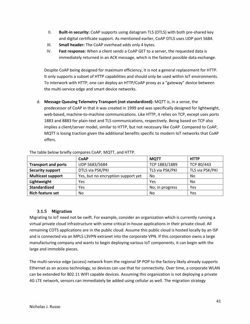
41 Nicholas J. Russo
II. Built-in security: CoAP supports using datagram TLS (DTLS) with both pre-shared key
and digital certificate support. As mentioned earlier, CoAP DTLS uses UDP port 5684.
III. Small header: The CoAP overhead adds only 4 bytes.
IV. Fast response: When a client sends a CoAP GET to a server, the requested data is
immediately returned in an ACK message, which is the fastest possible data exchange.
Despite CoAP being designed for maximum efficiency, it is not a general replacement for HTTP.
It only supports a subset of HTTP capabilities and should only be used within IoT environments.
To interwork with HTTP, one can deploy an HTTP/CoAP proxy as a “gateway” device between
the multi-service edge and smart device networks.
d. Message Queuing Telemetry Transport (not standardized): MQTT is, in a sense, the
predecessor of CoAP in that it was created in 1999 and was specifically designed for lightweight,
web-based, machine-to-machine communications. Like HTTP, it relies on TCP, except uses ports
1883 and 8883 for plain-text and TLS communications, respectively. Being based on TCP also
implies a client/server model, similar to HTTP, but not necessary like CoAP. Compared to CoAP,
MQTT is losing traction given the additional benefits specific to modern IoT networks that CoAP
offers.
The table below briefly compares CoAP, MQTT, and HTTP.
CoAP MQTT HTTP
Transport and ports UDP 5683/5684 TCP 1883/1889 TCP 80/443
Security support DTLS via PSK/PKI TLS via PSK/PKI TLS via PSK/PKI
Multicast support Yes, but no encryption support yet No No
Lightweight Yes Yes No
Standardized Yes No; in progress Yes
Rich feature set No No Yes
3.1.5 Migration
Migrating to IoT need not be swift. For example, consider an organization which is currently running a
virtual private cloud infrastructure with some critical in-house applications in their private cloud. All
remaining COTS applications are in the public cloud. Assume this public cloud is hosted locally by an ISP
and is connected via an MPLS L3VPN extranet into the corporate VPN. If this corporation owns a large
manufacturing company and wants to begin deploying various IoT components, it can begin with the
large and immobile pieces.
The multi-service edge (access) network from the regional SP POP to the factory likely already supports
Ethernet as an access technology, so devices can use that for connectivity. Over time, a corporate WLAN
can be extended for 802.11 WIFI capable devices. Assuming this organization is not deploying a private
4G LTE network, sensors can immediately be added using cellular as well. The migration strategy

42 Nicholas J. Russo
towards IoT is very similar to adding new remote branch sites, except the number of hosts could be very
large. The LAN, be it wired or wireless, still must be designed correctly to support all of the devices.
3.1.6 Environmental impacts on the network
Environment impacts are especially important for IoT given the scale of devices deployed. Although
wireless technologies become more resilient over time, they remain susceptible to interference and
other natural phenomena which can degrade network connectivity. Some wireless technologies are
even impacted by rain, a common occurrence in many parts of the word. The significance of this with
IoT is to consider when to use wired or wireless communication as for a sensor. Some sensors may even
be able to support multiple communications styles in an active/standby method. As is true in most
networks, resilient design is important in ensuring that IoT-capable devices are operable.
3.2 Resources and References
http://www.cisco.com/c/en/us/about/security-center/secure-iot-proposed-framework.html
http://www.cisco.com/c/r/en/us/internet-of-everything-ioe/internet-of-things-iot/index.html
http://ioeassessment.cisco.com/
http://www.cisco.com/web/about/ac79/docs/innov/IoT_IBSG_0411FINAL.pdf
http://www.cisco.com/c/dam/en_us/about/ac79/docs/innov/IoE.pdf
www.cisco.com/go/iot
BRKCRS-2444 - The Internet of Things: an Architectural Foundation and its Protocol
BRKSPG-2611 - IP Routing in Smart Object Networks and the Internet of Things
BRKIOT-2020 - The Evolution from Machine-to-Machine (M2M) to the Internet of Everything:
Technologies and Standards
DEVNET-1108 - Cisco Executives Discuss the Internet of Things
RFC6550 - RPL
RFC4919 - 6LoWPAN
RFC7252 - CoAP
MQTT Website
Related Documents