Event-Based Functional Build: An Integrated Approach to Body Development July 1999 Auto/Steel Partnership Program Body Systems Analysis Task Force 2000 Town Center - Suite 320 Southfield, MI 48075-1123

Welcome message from author
This document is posted to help you gain knowledge. Please leave a comment to let me know what you think about it! Share it to your friends and learn new things together.
Transcript

Event-Based Functional Build:
An Integrated Approach to Body Development
July 1999
Auto/Steel Partnership Program
Body Systems Analysis Task Force
2000 Town Center - Suite 320
Southfield, MI 48075-1123
ii
Body Systems Analysis Task Force Disclaimer
This publication is for general information only. The information contained within should not be
used without first securing expert advice with respect to its suitability for any given application.
The publication of this information is not intended on the part of the Body Systems Analysis
Task Force of the A/SP, or any other person named in this manual, as a representation or
warranty that the information is suitable for any general or particular use, or for freedom from
infringement of any patent or patents. Anyone making use of the information contained herein
assumes all liability arising from such use.
This publication is intended for use by Auto/ Steel Partnership members only. For more
information or additional copies of this publication, please contact the Auto/Steel Partnership,
2000 Town Center, Suite 320, Southfield, MI. 48075-1123 or (248) 945-7778.
Final Report – July 1999
Copyright 1999 Auto/Steel Partnership. All Rights Reserved.

iii
Preface
This report is one of a series of several reports published by the Auto/Steel Partnership
Body Systems Analysis Project Team on stamping and assembly variation, body measurement
systems and process validation. These reports provide a summary of the project research and are
not intended to be all inclusive of the research effort. Numerous seminars and workshops have
been given to individual automotive manufacturers throughout the project to aid in
implementation and provide direct intervention support. Proprietary observations and
implementation details are omitted from the reports.
This automotive body development report “Event-Based Functional Build: An Integrated
Approach to Body Development,” updates ongoing research activities by the Body Systems
Analysis Team and the Manufacturing Systems staff at The University of Michigan's Office for
the Study of Automotive Transportation. This report has two versions. First, an executive version
provides a basic overview of functional build and its benefits. A main report then examines
functional build in greater detail and addresses many implementation issues. We do note that
each version is a stand-alone report, thus, the information in the executive version is a subset of
the main report.
An over-riding goal of this research is to develop new paradigms that will drive
automotive body-in-white development and production towards a total optimized processing
system. Previous reports described fundamental research investigating simultaneous
development systems for designing, tooling and assembling bodies, and also flexible body
assembly. Since the inception of this research program, considerable emphasis has been focused
on benchmarking key world class body development and production processes. These
benchmarks created foundation elements upon which further advances could be researched and
developed.
This report summarizes recommendations for moving toward a new “functional build”
paradigm by tightly integrating the many individual activities ranging from body design and
engineering, on through process and tooling engineering. Revised stamping die tryout and
buyoff processes receive special emphasis in addition to the launch of stamping and assembly
tools.

iv
The researchers are indebted to several global automotive manufacturers for their on-
going dedication and participation in this research. They include Daimler-Chrysler Corporation,
Ford Motor Company, and General Motors Corporation. Each conducted experiments under
production conditions, involving hundreds of hours of effort, often requiring the commitment of
many production workers and engineering personnel. Although it may be impractical to mention
each one of these people individually, we do offer our sincere appreciation.
These reports represent a culmination of several years of effort by the Body Systems
Analysis Project Team. Team membership has evolved over the course of this project. They
include:
J. Aube, General Motors F. Keith, Ford
H. Bell, General Motors T. Mancewicz, General Motors
C. Butche, General Motors J. Naysmith, Ronart Industries
G. Crisp, Chrysler J. Noel, A/SP
T. Diewald, A/SP P. Peterson, USX
K. Goff Jr., Ford R. Pierson, General Motors
T. Gonzales, National Steel R. Rekolt, Chrysler
R. Haan, General Motors M. Rumel, A/SP
S. Johnson, Chrysler M. Schmidt, Atlas Tool and Die
The University of Michigan Transportation Research Institute conducted much of the
research and wrote the final reports. The principal research team from the Manufacturing
Systems Group was:
Patrick Hammett, Ph.D. (734-936-1121/[email protected])
Jay Baron, Ph.D. (734-764-4704/[email protected])
Donald Smith, Associate Director (734-764-5262)

v
Table of Contents
Preface......................................................................................................................................iii
Executive Summary ................................................................................................................. ix
1.0 Introduction ........................................................................................................................1
1.1 Functional Build: An Integrated Validation Approach ...............................................2
1.2 Research Methodology and Report Outline................................................................6
2.0 Evolution of the Functional Build Approach .....................................................................8
2.1 Recurring Body Development Challenges..................................................................8
2.1.1 Mean Deviations from Nominal ......................................................................8
2.1.2 Measurement System Challenges ..................................................................14
2.1.3 Correlation of Stamping and Assembly Dimensions......................................16
2.2 The Cpk “Game” ......................................................................................................20
2.3 Rise of Functional Build ..........................................................................................24
3.0 Functional Build Case Examples ...................................................................................... 27
3.1 Case Example 1: Non-rigid to rigid (Windshield to Body Side) ...............................28
3.2 Case Example #2: Non-rigid to Non-rigid: Body Side Outer to Inner.......................30
4.0 Functional Build Implementation Issues.......................................................................... 32
4.1 Categorization of Stamped Parts – “One Size Does Not Fit All" ..............................32
4.2 Part Submittal and Approval Criteria .......................................................................34
4.2.1 Timing-Dimensional Conformance Tradeoff .................................................35
4.2.2 Dimensional Validation Metrics....................................................................36
4.2.3 Defining the Mean Conformance “Gray Area” ..............................................36
4.2.4 Sample Size Planning....................................................................................39
4.3 Sub-assembly Build Issues.......................................................................................40
4.4 Roadblocks to Functional Build Implementation......................................................44
5.0 Event Based Functional Build .......................................................................................... 47
5.1 Die Source Tryout ...................................................................................................49
5.2 Production Source Tryout Process ...........................................................................50
6.0 The Future of Functional Build........................................................................................ 53

vi
List of Figures
Figure 1. Major Body Development Activities ........................................................................1
Figure 2. Sequential Manufacturing Validation .......................................................................2
Figure 3. Validating Stamping Processes.................................................................................4
Figure 4. Sources of Variation.................................................................................................9
Figure 5. Stamped Components in Body Side Assembly .......................................................10
Figure 6. Distribution of Mean Values ..................................................................................10
Figure 7. Distribution of Mean Deviations by Type of Part at Company A ............................11
Figure 8. Body Side Conformance and Clamping Strategies..................................................15
Figure 9. Common Dimensional Problem: Pass Cp – Fail Cpk...............................................22
Figure 10. Various Functional Build Implementation Strategies ..............................................25
Figure 11. Parallel assembly of a non-rigid surface to a rigid reinforcement ............................28
Figure 12. Body Side Outer and Windshield Reinforcement....................................................29
Figure 13. Example of Possible Effect of Stamping Mean Shift on Assembly .........................30
Figure 14. Body Side Outer to Body Side Inner Case Example................................................31
Figure 15. Part Categorization for Dimensional Evaluation .....................................................33
Figure 16. Decision model for tooling rework .........................................................................37
Figure 17. Mean Distribution and Part Acceptance..................................................................39
Figure 18. Body Side Assembly Mean Conformance ..............................................................42
Figure 19. Out of Parallel Condition on Fender-to-Hood Line .................................................44
Figure 20. Timing Process ......................................................................................................48
Figure 21. Die Source Tryout Process Flow ............................................................................49
Figure 22. Press Shop Tryout ..................................................................................................51
vii
List of Tables
Table 1. Mean Deviations for Several Manufacturers ............................................................12
Table 2. Change in Mean from Die Source to Production Source ..........................................13
Table 3. Mean and Variation Conformance by Clamping Approach ......................................16
Table 4. Correlation of Part Dimensions Before and After Assembly.....................................17
Table 5. Assembly Robustness to Stamping ..........................................................................18
Table 6. Mean Deviations: Stamping-to-assembly .................................................................19
Table 7. Cp versus Cpk Conformance at Tryout ......................................................................21
Table 8. Summary of Mean Dimensions................................................................................29
Table 9. Dimensional Summary of Components in Case Study..............................................31
Table 10. Assigning Values for the “Dimensional Gray Area” by Part Type............................38
Table 11. # Panels Measured by Tryout Run ...........................................................................40
Table 12. Body Side Assembly Mean Conformance Relative to Tolerance..............................42
Table 13. Sub-assembly Build Goals for Screw-body Evaluations...........................................43
Table 14. Benefits and Concerns of FB#1................................................................................45

viii

ix
Executive Summary
North Automotive manufacturers traditionally have utilized a sequential process
validation approach for the automotive body. This approach begins by validating individual
components, then small sub-assemblies, ultimately leading up to the finished body. This
approach assumes that the quality of each higher level assembly is predicated on the quality of
incoming, lower-level components. Validation at each step usually is measured by quality
indices such as Cp and Cpk. Unfortunately, this sequential approach has proven non-competitive
for car bodies, often resulting in missed development schedules and unnecessarily high costs for
process rework. Two attributes of sheet metal stamping and assembly processes inhibiting the
sequential approach are the inability to produce all component dimensions precisely at their
nominal specification, and the weak correlation in dimensions between non-rigid, lower-level
components and their assembled counterparts. Manufacturers attribute the deviations from
nominal specification to difficulties predicting metal flow during forming operations, as well as
the measurement process itself. In addition, no stamping die-maker has shown an ability to
significantly shift all part dimensions on a complex part close to nominal on a consistent basis,
even after several die-rework iterations. Manufacturers using Cpk buyoff indices, ultimately
modify tolerances to meet the required threshold to accommodate these mean deviations.
Furthermore, the lack of correlation between component dimensions and first-level sub-
assemblies suggests that some of this die rework is non-value added. These industry-wide
problems have led several manufacturers to adopt a more integrated process validation approach
called functional build.
The functional build approach to process development focuses on the customer perceived
quality of the final car body when evaluating the need for process changes. This approach shifts
the development focus from optimizing individual components to the whole car body, and
integrates product, process and manufacturing. Necessary changes are identified based on
lowest-cost solutions. These solutions might involve modifications to a product design, a
stamping die or an assembly process.
Manufacturers implement functional build using a process called a “screw-body” to
attach mating component parts. These parts are screwed (or riveted) in order to isolate the
influence of the assembly process. One concern with functional build is the subjective nature in
x
which decisions are made; research is needed to help quantify decision-making. Since the
original specifications become targets under the functional build paradigm, deviations from
specification may be partitioned into three regions: obvious die rework changes (large
deviations), obvious assembly tooling changes (small deviations) and uncertain rework changes
(between small and large deviations) requiring an integrated investigation. This research helps in
identifying these regions which should reduce the amount of subjective decision making. By
using an integrated validation approach like functional build, manufacturers may accelerate the
product development life cycle while saving costs in process development.
This report has two stand-alone versions: an executive version and a main report. Thus,
readers may choose the report that is appropriate for their needs. This version is the main report.

1
1.0 Introduction
The development of the automotive body represents a major challenge for all
manufacturers as they continuously strive to reduce the time and cost of bringing a new vehicle
to market. Using practices such as concurrent engineering, rapid prototyping and computer
simulation, manufacturers have reduced their development costs and lead-time by integrating
process engineering and manufacturing into the design phase or front end of body development.
Unfortunately, this integration has been far less common from the product and process design
phases forward into the manufacturing validation phases.
PartDesign
ProcessPlanning& Design
DieDesign
DieConstruction
Pilot
Weld ToolsConstruction
Weld ToolsTryout
Die SourceTryout
Production
Front End of Body Development Manufacturing Validation
Home LineTryout
Figure 1. Major Body Development Activities
Figure 1 shows the major stages of body development from part design to final tryout of
the assembly process using stamped parts off the home line (production presses). Once designs
are released and manufacturing processes are constructed, manufacturers traditionally evaluate
their parts using a sequential validation approach (see Figure 2). First, they validate that the
processes for stamped components are capable of meeting all design requirements. After each
component is approved, manufacturers validate their sub-assembly processes, and finally the
complete body-in-white. This sequential approach subscribes to the basic paradigm that final
product quality will be maximized if each individual component meets all its performance
requirements.

2
Component A
Component B
Component C
Component D
Component E
Subassembly AB
Subassembly CDE
Final Body
Componentmeets all designrequirements?
yes
no
ReworkProcess
Subassemblymeets all designrequirements?
ReworkProcess
Final Assemblymeets all designrequirements?
yesLaunch
Final Product
yes
no
ReworkProcess
no
Figure 2. Sequential Manufacturing Validation
Although sequential process validation is logistically simple and has proven effective for
many automotive components, few manufacturers have effectively executed this approach for
automotive body validation. The principal cause has been difficulties approving all component
characteristics to generic requirements such as Cpk > 1.67. This inability to meet all component
requirements subsequently reduces the allotted time to resolve assembly-related concerns
because of fixed production start dates for a new model. Even manufacturers relying on Cpk
evaluation criteria ultimately will abandon the sequential approach because of an inability to
meet all their original specifications. In contrast to the traditional sequential approach, several
manufacturers have adopted a more integrated validation approach known as Functional Build.
1.1 Functional Build: An Integrated Validation Approach
Under functional build, rather than validating components solely to their part print
specifications, manufacturers also evaluate components relative to their mating parts and
subsequent assembly processes. They strive to produce part dimensions to their original
specifications, but they treat these specifications as targets rather than absolute requirements.
Thus, if manufacturer experience difficulty meeting a particular component requirement, they
3
may resolve the problem in a downstream assembly process or change another related, mating
component more expediently. By analyzing components in their subsequent assemblies,
manufacturers also may find that certain original requirements are not critical to the final product
build. Here, a modification to the design print is less expensive than physically changing already-
constructed stamping dies.
When functional build is used, manufacturers may realize substantial cost savings over a
traditional process and product development life cycle. These savings result from eliminating
unnecessary process rework during the validation phase. Under functional build, rework
decisions focus on meeting final vehicle objectives and not necessarily on conformance to all
original component specifications.
Figure 3 illustrates the basic difference between sequential validation and the functional
build approach to dimensional validation decision-making. All manufacturers evaluate the
conformance of stamping dimensions to their design specifications. Typically, most dimensions
are within their specification limits; but some are not. At this point, manufacturers face a
decision. They can either rework the stamping process until all dimensions satisfy the print
requirements (traditional sequential approach) or adopt a functional build approach. Under
functional build, they may accept certain out-of-specification dimensions that can be corrected in
assembly and rework the others. In another scenario, a manufacturer may even allow a deviation
from the original design if it is unnoticeable to the customer.

4
Functional Build Decision
Measure StampingDimensions
Validate SubassemblyDimensions
Decision
Rework
Pass Cpk
Fail Cpk Accept Stamping Deviation(if deviation does not affect
subassembly quality
Figure 3. Validating Stamping Processes
The functional build evaluation process typically involves the construction of screw-
bodies. Most manufacturers construct screw-bodies off-line using fixtures or bucks. Rather than
build special fixtures for each subassembly, some manufacturers add extra locators to sub-
assembly check fixtures to allow them to “slow build” the stamped components.
One of the most common misconceptions of functional build is that it evaluates assembly
robustness to stamping variation. Functional build manufacturers only build one or two screw-
bodies for each sub-subassembly. Thus, the principal effect of constructing screw-bodies is an
evaluation of mean deviations and not variation. This requires manufacturers to first establish
short-term process stability prior to functional build evaluations.
In the functional build process, manufacturers usually assemble both the sub-assemblies
and the full screw-body with screws or rivets instead of the normal welding operations. They use
screws or rivets to minimize the distortion of components caused by welding. Thus, screw-body
assemblies help to determine whether individual components may feasibly produce an acceptable
sub-assembly or final assembly. Manufacturers assume that if the screw-bodies are acceptable,
they may eventually set-up weld tools to match them. In certain cases, a manufacturer may
produce a screw-body subassembly whose dimensions are unacceptable. This result, however,
does not necessarily trigger die rework. Manufacturers may decide to make a simple tool change
in assembly to bring the sub-assembly into specification rather than rework the stamping die.
Thus, the screw-body process also aids in setting-up and tuning-in welders.

5
Functional build typically occurs in two phases. In the first phase, manufacturers
construct “screw-body” assemblies using parts off regular production dies but at the construction
or tooling tryout source. The evaluation process provides a mechanism to conditionally approve
parts and subsequently trigger the shipment of dies (“die buy-off”) to the production facility. In
this process, manufacturers consider both the actual dimensional measurements of the
components and their relationship to mating components. A manufacturer might even choose to
rework certain in-specification dimensions if the changes will improve the overall
manufacturability or appearance of the final body. The primary objective of this first phase is to
correct those problems known to affect subsequent assembly operations, while delaying rework
decisions for those dimensions with unknown impacts. The second functional build phase occurs
after the dies are shipped to the production facility. The primary objective for this evaluation is
to produce a dimensionally acceptable finished body.
Most companies construct the first screw-body sub-assemblies between twelve and
fifteen months prior to the start of production. Additional screw-body prototypes are assembled
based on need and strategy. For example, manufacturers may construct additional screw-bodies
if a part significantly changes during tryout due to a design change or a manufacturing process
change. Section 5.0 includes a discussion of the timing of screw-body construction phases in
greater detail.
The screw-body process may result in significant changes to the original design without
impacting customer expectations. For example, although engineers may symmetrically design
the right and left side of a car body, a functionally built body may not have this characteristic.
The right side may build a couple of millimeters outward, while the left side may be inward from
design intent. As long as this lack of symmetry does not result in structural or appearance
problems such as inconsistent body gaps, the customer is unaware of the lack of conformance to
the original design. The argument for this approach is that manufacturers should not commit
resources to correct deviations from the original design unless the deviations affect customer
requirements.
When making an engineering change under the functional build approach, manufacturers
search for the least costly alternative without sacrificing product quality. For example, suppose
two mating dimensions that are significantly deviating from nominal result in a non-conforming
sub-assembly. Here, a functional build manufacturer would rework only one of the parts (the

6
least expensive) if this change could bring the sub-assembly closer to nominal. In an extreme
case, a manufacturer might choose to rework a dimension near its nominal if it is less expensive
than reworking a mating out-of-specification dimension. (Note that in observing functional build
practices, manufacturers rarely rework dimensions near nominal.)
This functional build rework approach differs from the traditional, sequential validation
approach. Under sequential validation, each part is evaluated independently against its design
specifications. Thus, a more expensive die or possibly several dies might require modification.
1.2 Research Methodology and Report Outline
The purpose of this report is to show why several manufacturers have adopted a
functional build approach and then explore various implementation strategies. Simply put,
functional build provides manufacturers with an integrated system to evaluate the effects of
stamping and sub-assembly mean deviations (not variation) on the final assembly build. The
principal appeal of this approach is to better integrate upstream manufacturing needs into
component requirements by shifting the body development focus from individual components to
the final body. The overall goal, as with any body dimensional validation strategy, is to minimize
overall development costs and timing while still meeting customer requirements.
The supporting data for this report are based on studies of seven manufacturers (General
Motors, Ford, Daimler-Chrysler, NUMMI (Toyota), Nissan, Opel and Renault). These
manufacturers have provided information on their validation processes. Several manufacturers
have augmented descriptions of their validation procedures with dimensional conformance data
from die source and production source tryout. In addition, a production case study was conducted
at each manufacturer on their body side assembly and the key components comprising it.
Manufacturers assembled 36 body sides using individual components with known dimensional
characteristics. They obtained the 36 samples for each component across six different production
runs (sample of 6 per run). These case studies provide the basis for examining the relationships
between stamping dimensional conformance and assembly conformance, in order to identify
more effective criteria and procedures to evaluate stamped parts prior to production.
In this report, the evolution of the functional build approach is examined. This approach
has arisen in response to three recurring challenges that all manufacturers must overcome to

7
reduce costs and lead-time for automotive body development. These challenges relate to
limitations predicting metal flow in stamping operations, measuring non-rigid stamped
components, and assessing the impact of stamping on assembly dimensional conformance. A
discussion follows of how certain manufacturers have managed these challenges through the
functional build process.
Section 3 presents case studies that highlight why the functional build approach works.
Section 4 addresses several functional build implementation issues. Among these issues are
potential conflicts between achieving dimensional and timing requirements, the use of the screw-
body as a decision tool, the development of evaluation criteria to evaluate stamped parts at the
die source, and the organizational requirements necessary to implement a functional build
approach. This section also examines several concerns from manufacturers currently using a
functional build approach.
Section 5 synthesizes various dimensional validation strategies used across manufacturers
into a common functional build process. This common process provides a roadmap for
companies trying to implement and/or improve their functional build activities. The last section,
Section 6, considers the future of functional build; whether it is a short or long-term strategy for
automotive body validation.

8
2.0 Evolution of the Functional Build Approach
This section examines why several manufacturers have adopted or are experimenting
with functional build. Understanding the evolution of functional build requires a fundamental
understanding of the recurring challenges with producing and assembling stamped body
components. This section examines these recurring challenges and then discusses how functional
build has evolved to meet them.
2.1 Recurring Body Development Challenges
Manufacturers have adopted functional build approaches to automotive body
development primarily in response to three recurring production validation challenges:
1. An inability to produce component mean dimensions at their nominal specification,
2. Limitations measuring non-rigid components and
3. Weak correlation between component dimensions and their resultant assemblies.
2.1.1 Mean Deviations from Nominal
Ideally, a manufacturer would like to produce each stamped component such that the
mean value at each measurement location is at its nominal specification with minimal variation.
Unfortunately, all manufacturers produce some component dimensions whose mean values are
off nominal. Figure 4 illustrates several potential mean-related issues for a stamping dimension.
First, a dimension may deviate from nominal at the die source. Second, a dimension may shift
from the die source to the home line. Although this particular dimension shifts away from
nominal, some dimensions improve. The main point is that manufacturers cannot assure that
rework at the die source will eliminate all mean deviations from the production source (press
shop). They must therefore evaluate mean deviations at both the die and production source.

9
-0.5
0
0.5
ProductionMean Deviation
Die Source to Home LineMean Shift
Nominal
Tryout Regular Production
-1
Die Source TryoutMean Deviation
LowerSpecification
1
1.5UpperSpecification
Mean Shift
Graph Legend:
Individual MeasurementsMean of the Stamping Run
Figure 4. Sources of Variation
Mean conformance is a concern with many stamping dimensions. Figure 5 illustrates five
body side assembly components from one of the case studies. These components include two
non-complex, rigid parts (Front and Center Pillar Reinforcements), and three complex and/or
non-rigid parts (Body Side, Roof Rail Outer, and Windshield Frame).

10
Center Pillar
Roof Rail
Windshield FrameReinforcement
Front Pillar Body Side
Figure 5. Stamped Components in Body Side Assembly
Figure 6 provides a histogram of the 143 mean dimensions (mean deviations) across
these five components. This figure indicates that the die construction and stamping process
typically generate parts whose mean deviations are normally distributed.
0%
5%
10%
15%
20%
25%
30%
35%
40%
45%
< -1.25 -1.25 ~ -.75 -0.75 ~ -.25 -0.25 ~ +.25 0.25 ~ .75 0.75 ~ 1.25 > 1.25
Range of Mean Deviations
% o
f D
imen
sion
s (1
43 to
tal) 65%: |Mean| < 0.5mm
Figure 6. Distribution of Mean Values

11
This normality of mean deviations typically occurs regardless of whether parts are
relatively simple, such as the front and center pillar reinforcements, or complex, such as the body
side or quarter panels. Although the mean distribution is approximately normal, some differences
exist in the variance of the mean deviation distribution. For example, simple rigid parts typically
have a tighter spread of mean deviations. Figure 7 compares the mean deviation distributions for
non-rigid panels versus rigid panels at Company A.
0%
20%
40%
60%
80%
100%
< -1.5 -1.5 ~ -0.5 -0.5 ~ 0.5 0.5 ~ 1.5 > 1.5
Range of Mean Deviations
% o
f D
imen
sion
s
Body Side Otr/ Q tr Inr (Non-rigid) Front/ C enter Pillar Reinforcements (Rigid)
Non-rigid: 44% |M e an| < 0.5
R igid: 83% |M e an| < 0.5
Figure 7. Distribution of Mean Deviations by Type of Part at Company A
The difficulty with producing all mean dimensions to nominal is not unique to these
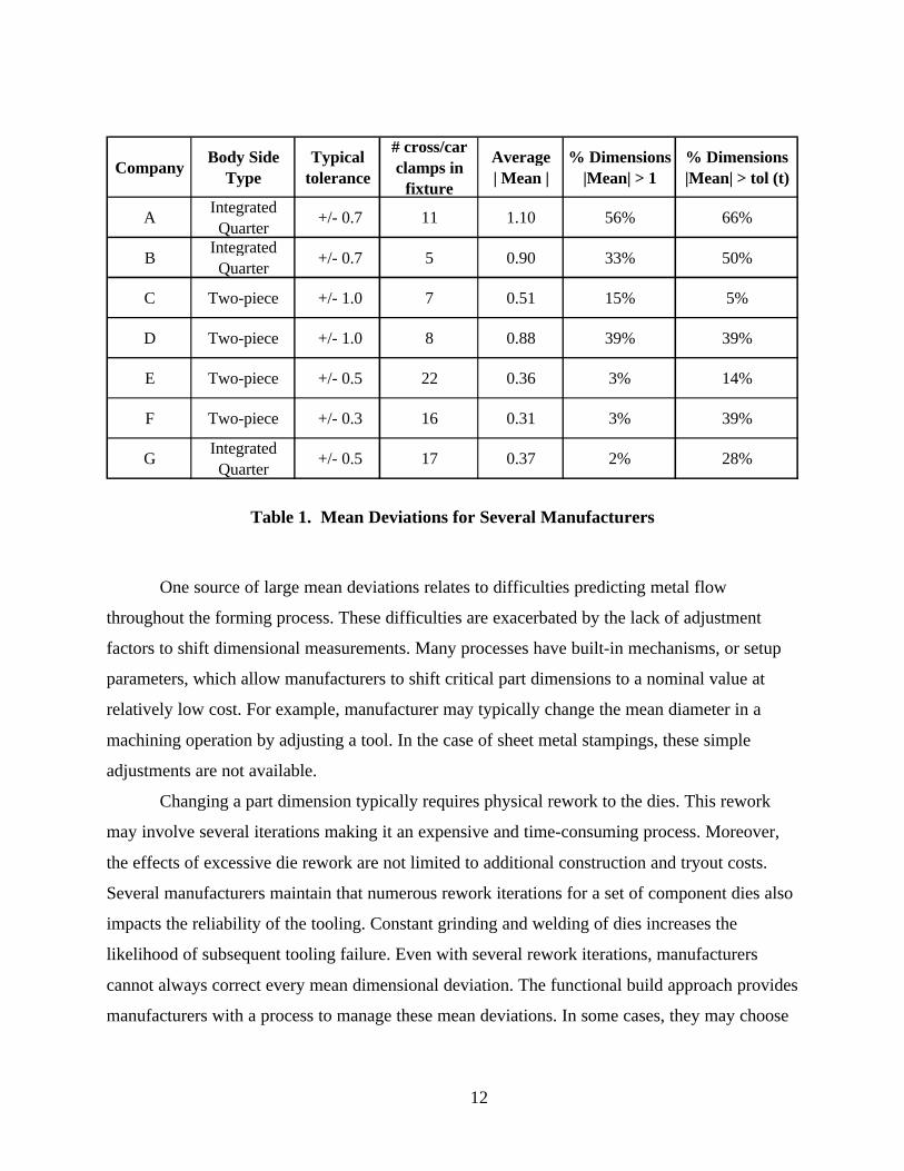
manufacturers. Table 1 provides a comparative look at mean deviations for all the manufacturers
studied. This table confirms that all of these manufacturers have mean deviation concerns,
although some manufacturers have fewer large deviations. Some of these differences do not
appear related to the die design process but rather to other factors such as panel complexity,
degree of constraint in the measurement system, assigned tolerances and rework strategies. For
example, Company A and B had the largest, most complex body sides. In terms of measurement
system constraint, Companies’ E-G use significantly more clamps to locate their body sides in
their checking fixtures. Another factor that explains the greater mean conformance at Company F
is the more stringent requirements at the die source. Company F places a greater emphasis on
reworking stamped panels that do not meet tight tolerances (say, +/- 0.3mm).
12
CompanyBody Side
TypeTypical
tolerance
# cross/car clamps in
fixture
Average | Mean |
% Dimensions |Mean| > 1
% Dimensions |Mean| > tol (t)
AIntegrated Quarter
+/- 0.7 11 1.10 56% 66%
BIntegrated Quarter
+/- 0.7 5 0.90 33% 50%
C Two-piece +/- 1.0 7 0.51 15% 5%
D Two-piece +/- 1.0 8 0.88 39% 39%
E Two-piece +/- 0.5 22 0.36 3% 14%
F Two-piece +/- 0.3 16 0.31 3% 39%
GIntegrated Quarter
+/- 0.5 17 0.37 2% 28%
Table 1. Mean Deviations for Several Manufacturers
One source of large mean deviations relates to difficulties predicting metal flow
throughout the forming process. These difficulties are exacerbated by the lack of adjustment
factors to shift dimensional measurements. Many processes have built-in mechanisms, or setup
parameters, which allow manufacturers to shift critical part dimensions to a nominal value at
relatively low cost. For example, manufacturer may typically change the mean diameter in a
machining operation by adjusting a tool. In the case of sheet metal stampings, these simple
adjustments are not available.
Changing a part dimension typically requires physical rework to the dies. This rework
may involve several iterations making it an expensive and time-consuming process. Moreover,
the effects of excessive die rework are not limited to additional construction and tryout costs.
Several manufacturers maintain that numerous rework iterations for a set of component dies also
impacts the reliability of the tooling. Constant grinding and welding of dies increases the
likelihood of subsequent tooling failure. Even with several rework iterations, manufacturers
cannot always correct every mean dimensional deviation. The functional build approach provides
manufacturers with a process to manage these mean deviations. In some cases, they may choose

13
to rework the tools, but in others they may allow certain component dimensions to deviate from
the design intent provided the assembly meets its specifications and functions properly.
Another challenge for manufacturers is maintaining a consistent mean between die source
tryout and the production source or home line tryout. Table 2 suggests that approximately 25 to
30% of dimensions may shift more than 0.5mm from the die source to the final part approval run
on the home line. Of those manufacturers in this study providing die source-to-production source
data, only Company F showed an overall improvement in mean conformance by the end of
tryout. Although they eliminated most of their significant mean deviations, they still entered
production with 15% of their dimensions having mean deviations in excess of 0.5mm. (Note:
these dimensions would not meet a Cpk requirement).
CompanyShift in Mean > 0.5mm
Die Source to Home LineDie Source Tryout
|Mean| > 0.5mmHome Line Tryout
|Mean| > 0.5mm
B 34% 33% 45%C 23% 30% 31%F 25% 25% 15%
% of Dimensions
Table 2. Change in Mean from Die Source to Production Source
Mean shifts from the die source to the production source affect whether manufacturers
should perform functional build evaluations at the die source, production source, or both. Based
on the historical problems of mean shifts, most manufacturers recognize the need to perform
functional build evaluations using home line tryout parts regardless of the die source results.
Given these mean shifts, some manufacturers question the usefulness of functional build at the
die source. The principal argument in support of functional build at the die source is that while
some dimensions may change, many do not. In addition, empirical studies suggest that the
majority of dimensions accepted out-of-specification at the die source are not reworked later at
the die source. Press shop rework typically involves new conditions rather than correcting known
conditions from die source evaluations. Thus, functional build evaluations at the die source allow
manufacturers to identify many potential build issues prior to shipping dies to the home line.
The lack of correlation in the mean from die source to press shop tryout does, however,
14
question the usefulness of adjusting tolerances at the die source solely to pass a Cpk criteria. Parts
requiring tolerance changes at the die source may require additional tolerance changes in the
press shop. Thus, manufacturers should delay formal print tolerance revisions until the
completion of home line tryout.
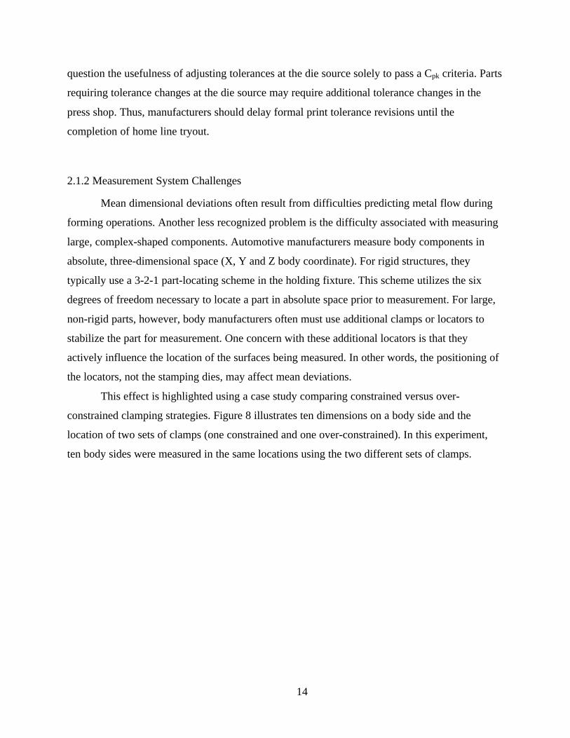
2.1.2 Measurement System Challenges
Mean dimensional deviations often result from difficulties predicting metal flow during
forming operations. Another less recognized problem is the difficulty associated with measuring
large, complex-shaped components. Automotive manufacturers measure body components in
absolute, three-dimensional space (X, Y and Z body coordinate). For rigid structures, they
typically use a 3-2-1 part-locating scheme in the holding fixture. This scheme utilizes the six
degrees of freedom necessary to locate a part in absolute space prior to measurement. For large,
non-rigid parts, however, body manufacturers often must use additional clamps or locators to
stabilize the part for measurement. One concern with these additional locators is that they
actively influence the location of the surfaces being measured. In other words, the positioning of
the locators, not the stamping dies, may affect mean deviations.
This effect is highlighted using a case study comparing constrained versus over-
constrained clamping strategies. Figure 8 illustrates ten dimensions on a body side and the
location of two sets of clamps (one constrained and one over-constrained). In this experiment,
ten body sides were measured in the same locations using the two different sets of clamps.

15
P5 P4 P3
P1
P8
P9
P10
P7
P6
P2
Over-Constrained (17 C/C Clamps)Constrained (9 C/C Clamps)
Figure 8. Body Side Conformance and Clamping Strategies
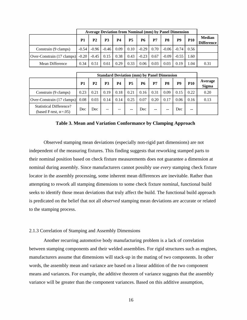
Table 3 indicates that the use of additional clamps may significantly shift mean
dimensions and/or reduce variation. In this study, three of the ten dimensions shifted more than
0.5mm. Interestingly, these mean shifts were not always toward nominal. For example, one
dimension (P10) shifted away from nominal using the more-constrained clamping system. The
point of this case study is not simply to show dimensional changes due to clamping, but to
question the ability to accurately assess mean deviations.
16
P1 P2 P3 P4 P5 P6 P7 P8 P9 P10Median
Difference
Constrain (9 clamps) -0.54 -0.96 -0.46 0.09 0.10 -0.29 0.70 -0.06 -0.74 0.56
Over-Constrain (17 clamps) -0.20 -0.45 0.15 0.38 0.43 -0.23 0.67 -0.09 -0.55 1.60
Mean Difference 0.34 0.51 0.61 0.29 0.33 0.06 0.03 0.03 0.19 1.04 0.31
P1 P2 P3 P4 P5 P6 P7 P8 P9 P10Average Sigma
Constrain (9 clamps) 0.23 0.21 0.19 0.18 0.21 0.16 0.31 0.09 0.15 0.22 0.20
Over-Constrain (17 clamps) 0.08 0.03 0.14 0.14 0.25 0.07 0.20 0.17 0.06 0.16 0.13
Statistical Difference? (based F-test, α=.05)
Dec Dec -- -- -- Dec -- -- Dec --
Average Deviation from Nominal (mm) by Panel Dimension
Standard Deviation (mm) by Panel Dimension
Table 3. Mean and Variation Conformance by Clamping Approach
Observed stamping mean deviations (especially non-rigid part dimensions) are not
independent of the measuring fixtures. This finding suggests that reworking stamped parts to
their nominal position based on check fixture measurements does not guarantee a dimension at
nominal during assembly. Since manufacturers cannot possibly use every stamping check fixture
locator in the assembly processing, some inherent mean differences are inevitable. Rather than
attempting to rework all stamping dimensions to some check fixture nominal, functional build
seeks to identify those mean deviations that truly affect the build. The functional build approach
is predicated on the belief that not all observed stamping mean deviations are accurate or related
to the stamping process.
2.1.3 Correlation of Stamping and Assembly Dimensions
Another recurring automotive body manufacturing problem is a lack of correlation
between stamping components and their welded assemblies. For rigid structures such as engines,
manufacturers assume that dimensions will stack-up in the mating of two components. In other
words, the assembly mean and variance are based on a linear addition of the two component
means and variances. For example, the additive theorem of variance suggests that the assembly
variance will be greater than the component variances. Based on this additive assumption,
17
manufacturers try to produce individual component mean dimensions at their nominal
specification with minimal variance. These manufacturers further assume that they may predict
their assembly outputs based on the measurements of the input components (i.e., input
component dimensions are correlated with their assembly outputs).
These assumptions, however, do not always hold with non-rigid components. These
components may continue to deform during weld processes. Some components will more closely
resemble the geometry of the fixtures used to orient them at time of assembly than their initial
measurements. Non-rigid component dimensions also may conform to more rigid dimensions
during assembly. The net effect is that non-rigid component measurements often poorly predict
final assembly measurements.
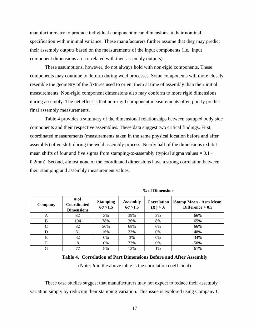
Table 4 provides a summary of the dimensional relationships between stamped body side
components and their respective assemblies. These data suggest two critical findings. First,
coordinated measurements (measurements taken in the same physical location before and after
assembly) often shift during the weld assembly process. Nearly half of the dimensions exhibit
mean shifts of four and five sigma from stamping-to-assembly (typical sigma values = 0.1 ~
0.2mm). Second, almost none of the coordinated dimensions have a strong correlation between
their stamping and assembly measurement values.
Company# of
Coordinated Dimensions
Stamping 6σσ >1.5
Assembly 6σσ >1.5
Correlation (R ) > .6
|Stamp Mean - Asm Mean| Difference > 0.5
A 32 3% 39% 3% 66%B 104 78% 36% 8% 65%C 32 50% 68% 6% 66%D 31 16% 23% 0% 48%E 32 0% 3% 0% 34%F 8 0% 33% 0% 50%G 77 8% 13% 1% 61%
% of Dimensions
Table 4. Correlation of Part Dimensions Before and After Assembly
(Note: R in the above table is the correlation coefficient)
These case studies suggest that manufacturers may not expect to reduce their assembly
variation simply by reducing their stamping variation. This issue is explored using Company C

18
as an example because their variation significantly increased in assembly. To examine assembly
robustness, two groups were created: a set of panels with low stamping variation and a set with
high variation. Table 5 summarizes the results. In the windshield area, the second set of panels
exhibited large stamping mean shifts resulting in significantly higher assembly variation. In the
center pillar area, the high stamping variation group exhibits similar behavior as the low
variation group. The main difference in the center pillar area is that the high variation group was
not the result of large between run mean shifts. Thus, low levels of assembly variation appear
related to control of stamping mean shifts and the assembly process itself. Moreover, in the
absence of large mean shifts, these data suggest that assembly processes essentially are robust up
to six sigma levels of at least 1~1.5mm (6 x 0.25=1.5). Therefore, reducing stamping variation
below these levels is unlikely to automatically reduce assembly variation.
Body Side Area Panel SetStamping
Average σσAssembly
Average σσWindshield #1 0.11 0.19
#2 0.37 0.42Center Pillar #1 0.12 0.34
#2 0.28 0.36
Table 5. Assembly Robustness to Stamping
Table 6 examines mean conformance from stamping-to-assembly by type of stamped
component. One interesting finding is that even though Company D has significant mean
deviations on their body side outer stamping, they effectively compensate for these deviations
and produce assemblies closer to nominal. One hypothesis supported by the above data is that
this manufacturer has better mean conformance in their reinforcements and also is effectively
managing their assembly process to minimize dimensional changes. In contrast, Company G has
excellent mean conformance on their body side outer and its reinforcements, but relatively poor
mean conformance in assembly. This finding suggests that mean conformance in assembly is
clearly impacted by assembly process setup and not simply a function of stamping mean
conformance. Company E, which utilizes an over-constrained measurement approach, has the
highest mean conformance in both stamping and assembly. Still, one-third of their stamping
dimensions shift in excess of 0.5mm during assembly, although few dimensions shift from in-

19
specification to more than 1mm away from nominal. These results demonstrate the importance of
effectively compensating for stamping deviations throughout assembly processing.
CompanyBody Side/
Quarter OuterReinforcements
Non-Rigid Inner Panel
Body Side Assembly
A 56% 1% 30% 40%
B 33% -- 16% 35%
C 15% 3% 0% 39%
D 39% 0% 0% 6%
E 3% -- -- 6%
F 3% 17% 17% 8%
G 2% 6% 8% 33%
% of Dimensions with Mean Bias > 1.0 mm
Table 6. Mean Deviations: Stamping-to-assembly
(Note: excludes cases where fewer than 10 dimensions are measured)
Several explanations exist for the lack of correlation between individual components and
their respective assemblies. Among them are:
• Deformation of metal during the weld process,
• Changes in the part locating schemes between stamping and assembly,
• Conformance of non-rigid component dimensions to other rigid areas of the assembly and
• Measurement system errors.
This lack of correlation presents serious ramifications for those manufacturers utilizing
build to nominal criteria such as Cpk. Here, manufacturers rework dies at both the die source and
the production facility trying to meet Cpk for all component dimensions. Estimates of the rework
costs at these manufacturers suggest that rework may account for 20 to 30% of the die costs. The
above correlation analysis suggests that this rework may have minimal impact on the final body
dimensional accuracy. In one study of a vehicle launch, a manufacturer reported that over 70%
of root causes for major body dimensional variation problems were related to assembly fixture

20
issues. Therefore, if launch dates are fixed, delaying assembly tryout to rework individual
components may not allow sufficient time to resolve the primary causes of final body
dimensional problems.
Through experience, most manufacturers recognize that they may produce an acceptable
body without meeting Cpk requirements for all single component dimensions. They ultimately
make tolerance revisions to approve parts that fail Cpk requirements. In some extreme cases, a
manufacturer may even stop rework, waiting for timing pressures to force tolerance revisions in
order to start production. The next section discusses how the recurring difficulties of producing
and measuring mean stamping dimensions to nominal inhibits the effective use of Cpk as the
primary decision criteria for stamped components.
2.2 The Cpk “Game”
Most manufacturers using sequential validation rely on Cp and Cpk indices to approve
parts for the next validation phase. This approach follows the basic quality paradigm, which
suggests that in order to produce final body dimensions at their desired nominal (target) value
with minimum variation, manufacturers must produce the input dimensions at their nominal
values, and with even less variation. In stamping, many manufacturers subscribe to this approach
by requiring that all dimensions on each individual stamped part achieve a Cp and Cpk > 1.33 (or,
Cp and Cpk >1.67). Both the Cp and Cpk index assess the ability of a process to produce outputs
within their specification limits. For example, Cp is determined by dividing the total tolerance by
six times the standard deviation. The Cpk index differs from Cp because it includes the deviation
of the mean from its nominal in assessing process capability. These indices have become widely
accepted in the automotive industry because they provide objective criteria to validate the
conformance of components to their design requirements. By using this criteria, manufacturers
hope that conformance to specification of individual stamped components will result in more
consistent final body measurements.
Empirical studies of stamping tryout suggest that even if manufacturers achieve Cp
requirements, they often fail to achieve Cpk requirements due to mean deviations from nominal.
In other words, their processes have sufficiently low variation but are off target. For the body
side case study dimensions presented in Table 7, dimensions with mean bias greater than 0.3mm

21
typically would not pass Cpk requirements for tolerances of +/- 0.7mm even though many would
pass a Cp criteria. Even Company F, which has greater mean and variation conformance than the
others, would not meet Cpk criteria for nearly half their dimensions.
Company% Dimensions
Cp > 1.33 (Pass) % Dimensions
Cpk > 1.33 (Pass) % Dimensions Mean Bias > .3
% Dimensions Bias > .3 and
Cpk > 1.33 (ok)
% Dimensions Bias > .3 and
Cp > 1.33 (ok)
B 73% 19% 69% 11% 72%
C 63% 33% 57% 10% 59%
D 71% 26% 56% 0% 69%
F 92% 58% 47% 20% 88%
Table 7. Cp versus Cpk Conformance at Tryout
(Note: above Cp and Cpk calculations are based on generic tolerances of +/- 0.7)
In general, the use of a Cpk index is most effective under the following conditions:
adjustment factors exist to shift mean dimensions, tolerance stack-ups are predictable and a
reliable system exists to measure stamped parts. Unfortunately, none of these conditions
currently exist in stamping. Consider the following issues facing automotive manufacturers
relying on Cpk:
1. Many part dimensions (primarily non-rigid) that do not meet Cpk acceptance criteria are
found to have little impact on the resultant assembly due to poor correlation between
stamping measurements and their resultant assemblies.
2. Many part dimensions that meet Cp requirements fail Cpk. Thus, many stable processes
are reworked. In some cases, this rework may even add to the inherent process variation.
3. Efforts to rework dies to pass Cpk criteria often drive-up die costs and lead-time.
4. Even with extensive die rework, manufacturers ultimately make tolerance adjustments to
pass the Cpk acceptance criteria for many part dimensions questioning the value of the
original rework attempts.
5. Many parts which eventually pass Cpk at the die source still require additional rework
once the dies are shipped to the production facility because of inherent differences in the
stamping presses between facilities.

22
In addition to these issues, the use of Cpk also may have an adverse effect on the
assignment of part tolerances. Consider the common result of a capability study shown in Figure
9. This dimension has extremely good capability in terms of variation, but the mean is off
nominal. Since this manufacturer must pass a Cpk criteria, they may choose to either rework this
die or modify the manufacturing tolerance. If they modify the tolerance, the adjustment might
consist of a bilateral expansion of the tolerance from +/- 0.75mm to +/- 1.1mm just to pass Cpk.
This bilateral expansion often occurs without evidence that tolerance relief is needed or
allowable on both sides of nominal. Therefore, even though this process is really capable of
producing panels within a range of 1mm (i.e. six x sigma < 1), a manufacturer might allow less
control of stamping variation simply to compensate for the mean deviation. In this instance, the
press shop could have a mean shift over 1mm and still fall within the –1.1mm lower
specification if they bilaterally expand the tolerance. As an alternative to widening tolerances,
this manufacturer may even try to rework this acceptable part to avoid the logistical
inconveniences of tolerance expansions.
LSL
-.75
USL
+.75
Nominal
0
Cp = 1.9
Cpk = 0.6Mean= .5
sigma= .13
Figure 9. Common Dimensional Problem: Pass Cp – Fail Cpk
To avoid the potential effects of bilateral expansions, the use of lateral tolerance
adjustments through functional build is recommended. In this approach, manufacturers re-assign
target values based on the functional build means and then laterally shift tolerances accordingly.

23
The preceding example suggests setting the target to 0.5mm and laterally shifting the tolerances
to -0.25/+1.25. Thus, the overall tolerance width would remain the same.
Another potential effect of using Cpk relates to the assignment of original tolerances.
Manufacturers with Cpk requirements push for wider tolerances to allow greater mean deviations.
They also expand tolerances based on the actual Cpk requirement. For instance, manufacturers
with a requirement of Cpk > 1.0 typically have tighter tolerances than those requiring Cpk >1.67.
For Cpk > 1.0, manufacturers assign tolerances based on +/- 3sigma. If the requirement is 1.67,
manufacturers need tolerances of +/- 5sigma. Therefore, even if the inherent variation of both
manufacturers is the same, the manufacturer with the 1.67 requirement will need significantly
larger tolerances. One interesting phenomenon is that those manufacturers with higher Cpk
standards (e.g., Cpk > 1.67) and subsequently larger tolerances tend to have more stamping
variation than those companies not using Cpk. In other words, widening tolerances to address
mean deviation concerns may inadvertently lessen control of variation.
These problems with tolerances and the use of Cpk lead to what may be referred to as the
“Cpk game”. The Cpk game is as follows:
At Die Source Tryout:
• Parts fail Cpk because of mean bias.
• Manufacturers rework dies in efforts to pass Cpk.
• After unsuccessful rework attempts, specifications are changed for many dimensions
to pass Cpk.
• Manufacturers ship the dies.
Home Line Tryout:
• Part dimensions change from die source to home line.
• Manufacturers rework dies in efforts to pass Cpk.
• After unsuccessful rework attempts, specifications are changed for many dimensions
and parts are approved for production.
The word “game” is used because most manufacturers really do not use the Cpk index to
determine a good part from a bad one. Rather, they figure out ways to manipulate the index so

24
that parts they believe are acceptable may be labeled accordingly. Thus, the use of Cpk becomes
more of a game of numbers rather than a validation tool.
The effect of this “game” is low confidence in the Cpk results from dimensional studies at
both the die source and press shop. Since manufacturers rarely demonstrate an ability to meet Cpk
acceptance criteria or the necessity to do so to produce acceptable bodies, many manufacturers
are examining alternative methods and evaluation criteria. The following section discusses the
rise of functional build as an alternative approach to the traditional sequential validation and the
use of Cpk.
2.3 Rise of Functional Build
Functional-build type practices have existed for many years. The principal evaluation
tool, or screw-body process, may be traced to at least the early 1970s to a process known as
“screw and scribe” or matching. Manufacturers would screw mating components together to
check for assembly interference. One Japanese manufacturer iterated on this process and began
using it as an evaluation tool for die rework decisions. By performing functional build
evaluations, this manufacturer has been able to eliminate unnecessary rework and reduce overall
validation time for new vehicle launches.
Figure 10 illustrates the spectrum of the various approaches for body dimensional
validation. On one end is pure net build or sequential validation. This approach consists of
insuring that component dimensions achieve all of their requirements prior to evaluating
assemblies. If any dimension does not conform, it is reworked until it does. On the other end of
the spectrum is pure functional build. In this approach, manufacturers evaluate the vehicle from
the top-down. They first construct a full screw-body once stable metal is achieved (i.e., the
process is repeatable with no unacceptable splits, wrinkles). The evaluation of this screw-body
vehicle then drives changes to those sub-assemblies affecting final body-in-white conformance.
Then, only if they cannot resolve the problem in the sub-assembly tooling level would they go
back and rework dies.
The principal concern with pure functional build is timing requirements for
modifications. If manufacturers wait until the full screw-body evaluation, they reduce some of
the time available to make die or process modifications. To balance the risks of unnecessary
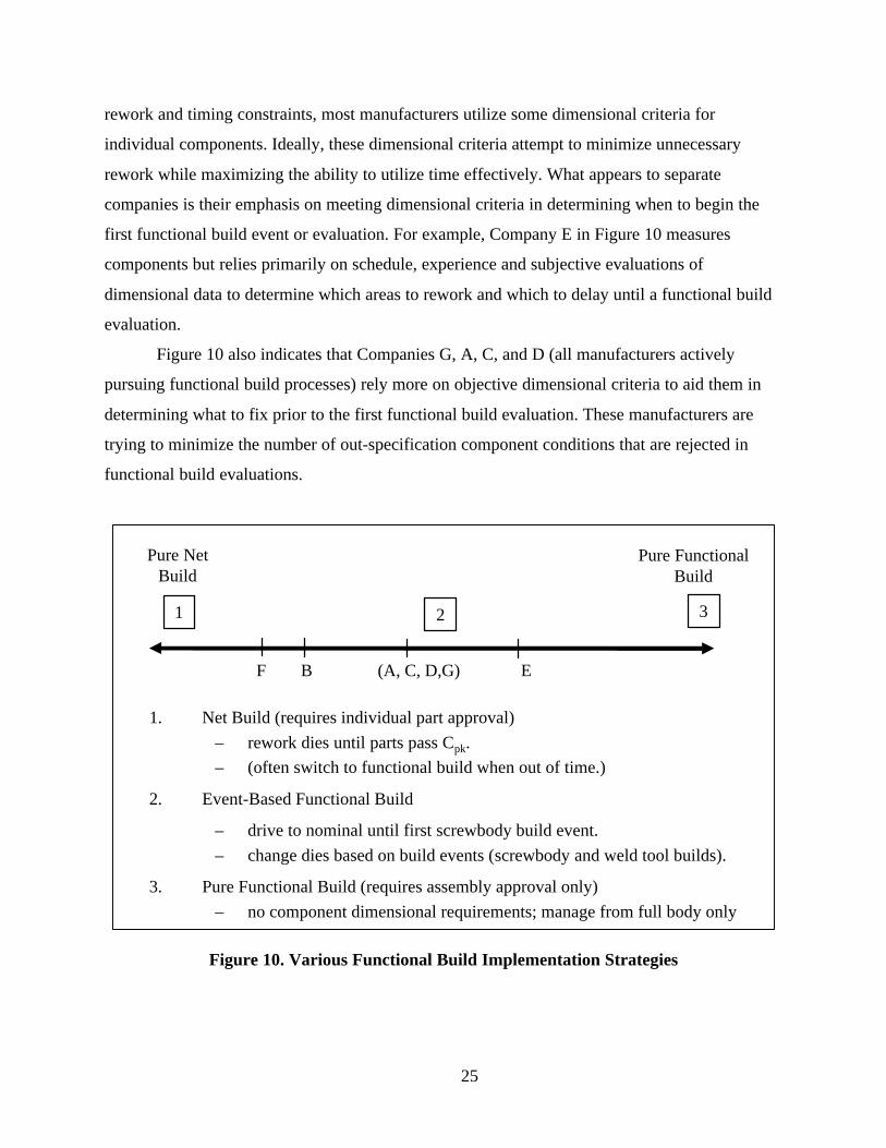
25
rework and timing constraints, most manufacturers utilize some dimensional criteria for
individual components. Ideally, these dimensional criteria attempt to minimize unnecessary
rework while maximizing the ability to utilize time effectively. What appears to separate
companies is their emphasis on meeting dimensional criteria in determining when to begin the
first functional build event or evaluation. For example, Company E in Figure 10 measures
components but relies primarily on schedule, experience and subjective evaluations of
dimensional data to determine which areas to rework and which to delay until a functional build
evaluation.
Figure 10 also indicates that Companies G, A, C, and D (all manufacturers actively
pursuing functional build processes) rely more on objective dimensional criteria to aid them in
determining what to fix prior to the first functional build evaluation. These manufacturers are
trying to minimize the number of out-specification component conditions that are rejected in
functional build evaluations.
Pure NetBuild
1. Net Build (requires individual part approval)
– rework dies until parts pass Cpk.
– (often switch to functional build when out of time.)
2. Event-Based Functional Build
– drive to nominal until first screwbody build event.
– change dies based on build events (screwbody and weld tool builds).
3. Pure Functional Build (requires assembly approval only)
– no component dimensional requirements; manage from full body only
1 32
F B (A, C, D,G) E
Pure FunctionalBuild
Figure 10. Various Functional Build Implementation Strategies
26
One interesting comparison across the manufacturers in this study is experience using
functional build. Company E has utilized functional-build the longest and appears the most
comfortable relying on subjective decision-making. They also have greater confidence in their
ability to control variation even if they cannot produce every mean dimension at nominal. Given
their lower experience levels, the other manufacturers making a transition toward functional
build may benefit from the use of objective criteria to determine when to start the functional
build process. This middle ground between pure net build and pure functional build is referred to
as event-based functional build for the purposes of this report. The term event-based implies that
timing considerations also play a key role in the establishment of criteria.
Furthermore, event-based functional build is characterized as a process utilizing objective
criteria that are relatively loose in dimensional conformance and stringent in terms of timing.
Some component criteria are necessary to insure part dimensions are relatively stable without
excessive mean deviations. In other words, it is recommended that manufacturers get all
component dimensions within an acceptable window prior to performing a functional build
evaluation. (Note: criteria that define this dimensional window are established in Section 5).
27
3.0 Functional Build Case Examples
The use of the functional build process appears most applicable in the assembly of either
two non-rigid components or a non-rigid to a rigid component. In general, a component may be
considered non-rigid if it has a blank thickness < 1.5mm. These components typically do not
become rigid until after they are assembled. Of course, even a flimsy body side outer panel has
certain areas that are quite rigid such as the rear door opening near the wheelhouse. Moreover, a
small, simple part with a blank thickness less than 1.5 could also be rigid. Still, a 1.5mm
guideline is used for part classification.
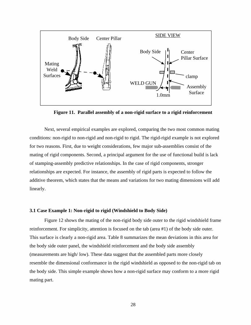
To demonstrate why functional build works, consider the mating of the center pillar
reinforcement and the body side panel in Figure 11. The center pillar reinforcement is a
structural component and thus will have greater influence on the final assembly. If the body side
panel is 1mm outboard from the centerline of the car, but the center pillar is at nominal, the
overall assembly will likely shift toward nominal. This shift occurs because the mating surfaces
are in parallel. Thus, the less rigid body side panel will conform to the rigid inner structure.
Under the traditional approach, a manufacturer would likely rework the body side panel because
the outboard stamping condition would cause this part dimension to fail its Cpk requirement. In
contrast, a functional build manufacturer would assemble these two components and only make
rework decisions based on the resultant assembly and not necessarily on Cpk compliance. In
some cases, the resultant assembly might still deviate from nominal, but this manufacturer may
find it easier to adjust an assembly process locator than physically alter a stamping die.
28
Body Side Center Pillar Surface
clamp
AssemblySurface1.0mm
SIDE VIEW
WELD GUN
Body Side Center Pillar
MatingWeld
Surfaces
Figure 11. Parallel assembly of a non-rigid surface to a rigid reinforcement
Next, several empirical examples are explored, comparing the two most common mating
conditions: non-rigid to non-rigid and non-rigid to rigid. The rigid-rigid example is not explored
for two reasons. First, due to weight considerations, few major sub-assemblies consist of the
mating of rigid components. Second, a principal argument for the use of functional build is lack
of stamping-assembly predictive relationships. In the case of rigid components, stronger
relationships are expected. For instance, the assembly of rigid parts is expected to follow the
additive theorem, which states that the means and variations for two mating dimensions will add
linearly.
3.1 Case Example 1: Non-rigid to rigid (Windshield to Body Side)
Figure 12 shows the mating of the non-rigid body side outer to the rigid windshield frame
reinforcement. For simplicity, attention is focused on the tab (area #1) of the body side outer.
This surface is clearly a non-rigid area. Table 8 summarizes the mean deviations in this area for
the body side outer panel, the windshield reinforcement and the body side assembly
(measurements are high/ low). These data suggest that the assembled parts more closely
resemble the dimensional conformance in the rigid windshield as opposed to the non-rigid tab on
the body side. This simple example shows how a non-rigid surface may conform to a more rigid
mating part.

29
Area #2
Area #1
Area #3
Figure 12. Body Side Outer and Windshield Reinforcement
AreaBody Side
MeanWindshield Frame
MeanAssembly
Mean
#1 -0.7 0.5 0.6
#2 0.9 -0.2 -0.4
Table 8. Summary of Mean Dimensions
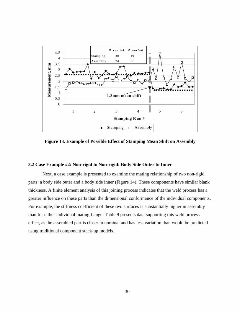
One concern with using functional build (or even net build) is significant shifts in the
stamping mean between runs. For instance, if a manufacturer accepts a mean deviation through a
functional build evaluation by making an adjustment to assembly tooling, then significant
changes to the stamping mean may cause severe problems in assembly. Figure 13 shows a run
chart for dimension #3 on the body side outer before and after assembly. This figure shows that
even though the mean is off nominal for four stamping runs, the assembly process is stable.
However, when the mean shifted significantly closer to nominal at the start of the fifth run, the
assembly variation increased. In this instance, maintaining a consistent stamping mean appears
more important than the relative location of this dimension to nominal.
30
0
0.5
1
1.5
2
2.5
3
3.5
44.5
1 2 3 4 5 6
Stamping R un #
Mea
sure
men
t, m
m
Stamping Assembly
σσ r u n 1 - 4 σσ r u n 5 - 6
Stamping .30 .19
Assembly .24 .80
1.3mm mean shift
Figure 13. Example of Possible Effect of Stamping Mean Shift on Assembly
3.2 Case Example #2: Non-rigid to Non-rigid: Body Side Outer to Inner
Next, a case example is presented to examine the mating relationship of two non-rigid
parts: a body side outer and a body side inner (Figure 14). These components have similar blank
thickness. A finite element analysis of this joining process indicates that the weld process has a
greater influence on these parts than the dimensional conformance of the individual components.
For example, the stiffness coefficient of these two surfaces is substantially higher in assembly
than for either individual mating flange. Table 9 presents data supporting this weld process
effect, as the assembled part is closer to nominal and has less variation than would be predicted
using traditional component stack-up models.

31
Weld
Weld
Dimension
Body Side Outer Body Side Inner
Figure 14. Body Side Outer to Body Side Inner Case Example
PartBlank Gauge
Mean Sigma
Body Side Outer 0.9 mm 0.11 0.43Body Side Inner 0.8 mm -0.41 0.18
Body Side Assembly 0.05 0.2
Table 9. Dimensional Summary of Components in Case Study

32
4.0 Functional Build Implementation Issues
This section examines several functional build implementation issues. These include:
1. Type of part,
2. Part submittal and approval criteria,
3. Subassembly evaluation criteria, and
4. Organizational requirements.
4.1 Categorization of Stamped Parts – “One Size Does Not Fit All"
Although organizational advantages exist with one process for all components, the reality
is that the ability of manufacturers to meet dimensional criteria is largely related to the type of
part. For example, part buy-off for small, relatively non-complex reinforcements is less
cumbersome than for large or complex-shaped panels. Moreover, major outer panels typically
have more problems than non-rigid inner panels because they have additional criteria such as
parallelism of body gap lines. Differences in the type of part also impact the functional build
process. Non-rigid panels tend to have larger mean deviations, but also are more likely to have
these deviations compensated in assembly. In other words, non-rigid dimensions are more likely
to shift during assembly, especially if they join to a rigid part.
As a general rule, manufacturers typically produce parts whose blank thickness is greater
than 1.5mm closer to nominal and with less variation. Note, however, that certain heavy gauge
panels do not follow this rule. For example, some stamped components such as the windshield
frame inner reinforcement or front body hinge pillar reinforcement historically have twists or
other large deviations resulting from complex forming operations. In addition, some small, light-
gauge panels may exhibit similar properties as thick reinforcements.

33
Part Category
Major Outer Panels(e.g. Fender, Quarter Outer
Body Side Outer)
Non-rigid Inner(t < 1.5)
(e.g. rocker inner, floor pan)
Rigid-Complex Panels(t >= 1.5 and complex
form or twist)(e.g. windshield frame reinforcement)
StandardNon-rigid Inner/ Complex
Functional Build Parts
Rigid/ Non-Complex Panels(t >= 1.5)
(e.g. Strut Housing)
Non-Functional Build Parts
t = blank metal thickness
Figure 15. Part Categorization for Dimensional Evaluation
Due to differences in panel rigidity, complexity and body requirements, the
recommendation is to establish three part categories: simple/rigid, standard and major outer.
Figure 15 provides examples for each of these categories. The intent of these categories is to
allow the development of multiple criteria to better utilize tryout resources. For instance,
manufacturers should be able to meet more stringent criteria for simple/rigid parts and therefore
focus functional build resources on evaluating standard and major outer panels. Although blank
material thickness should be considered in part categorization, die engineering, stamping, and the
functional build team should jointly agree on the final classification.
A functional build approach is not recommended for simple/rigid parts. First, since
manufacturers usually are capable of meeting stricter dimensional requirements for these parts in
die construction and tryout, they may shift functional build resources to concentrate on the more
challenging non-rigid panels. In addition, by requiring stricter dimensional conformance for rigid
panels, evaluations of non-rigid panels should be more effective because of greater confidence in
the location of mating flanges and other part dimensions. Finally, the greater the panel rigidity,
the less likely manufacturers may compensate for large mean deviations in assembly. Benchmark
studies further confirm that producing rigid reinforcements closer to their original specifications
improves the likelihood of producing dimensionally correct assemblies. Note, however, that the
functional build process would still use rigid panels to construct screw-bodies in order to
34
evaluate other mating parts within a sub-assembly. As a result of the build, manufacturers might
even modify a rigid component that is within specification to compensate for a problem in a non-
rigid part.
4.2 Part Submittal and Approval Criteria
Prior to establishing functional build criteria, it is important to first recognize the
difference between submittal and approval criteria. The purpose of submittal criteria is to
identify when to construct and evaluate screw-body assemblies. For example, manufacturers
using an event-based functional build strategy seek submittal criteria that if met, reduce the
number of component dimensions rejected in the first screw-body build event without
prohibiting the ability to meet timing schedules. Contrast this objective with those for approval
criteria where the principal objective is to insure a dimensionally correct final body. Under
functional build, component approval ultimately is determined by the conformance of the sub-
assembly and the full body assembly. Of course, since functional build only evaluates mean
deviations, variation requirements for individual components should be consistent between
submittal and approval criteria.
To demonstrate the role of submittal criteria, suppose a mating flange on a surface is
4mm from nominal and the other surface is 1mm from nominal. The ability to evaluate the mean
deviation on the second flange is limited by the fact that its mating component is not even close
to nominal (4mm). Empirical studies of functional build programs suggest that component parts
need to be within some dimensional window (e.g., less than 0.5-1.0 mm greater than
specification limits) to effectively perform an evaluation. Organizational pressure to reduce
vehicle development time also decreases the available time after functional build evaluations to
perform modifications. If time is available to rework a significant mean deviation prior to the
first functional build, manufacturers may prefer to minimize their risk of rejection and perform
the rework. The rationale is that for certain large mean deviations (e.g., greater than 1mm out-of-
tolerance), the risk for subsequent rework following a functional build exceeds the risk of
unnecessarily modifying a die prior to the build.
The purpose of this section is to examine the central issues regarding the establishment of
effective submittal criteria. Subassembly approval criteria are examined in the following section.

35
4.2.1 Timing-Dimensional Conformance Tradeoff
A fundamental issue in developing a functional build strategy is how manufacturers
address timing-dimensional conformance conflicts. These conflicts occur when a component
does not meet its dimensional requirements at the time of a validation event such as the first
functional build screw-body. Essentially, manufacturers must decide whether to proceed with an
event using components with known problems or delay the build until the parts meet all
requirements. Reasonable arguments may be made for either decision. First, by delaying the
build, the effectiveness of the build evaluation increases because components more closely
reflect their production conditions. On the other hand, meeting all timing deadlines is critical to
managing the overall development process because of the inter-dependencies of other concurrent
and subsequent activities. For example, delaying the evaluation of a body side assembly to wait
for the body side stamped component could subsequently delay the evaluation of the center
pillar. Obviously, certain extreme cases may arise where a particular component does not even
remotely resemble the intended part and a special recovery plan may be needed. However, if the
majority of dimensions are within specification, manufacturers typically will benefit more from
performing the evaluation at this point than delaying the overall process. Empirical evidence
further suggests that meeting timing deadlines is critical to realizing the potential savings
associated with a functional build approach. Thus, under the event-based functional build
approach, timing is sacred.
Under this timing-sacred philosophy, manufacturers should view dimensional criteria as
goals rather than absolute requirements. In other words, manufacturers should make every effort
to meet all submittal goals, but ultimately should submit components based on timing. Given this
timing priority, manufacturers may question the usefulness of even having dimensional goals.
The argument in support of goals is that meeting them lowers the likelihood of rework following
a functional build evaluation.
One implementation issue with an event-based approach is allotting resources to make
die modifications between build evaluations. Under event-based functional build, manufacturers
may delay certain die rework or engineering changes at the die source in order to meet timing
deadlines. In this scenario, manufacturers should not expect to ship dies immediately following
36
the functional build evaluation. One benefit of a modification period following functional build
is that manufacturers may batch change screw-body rework requests with late engineering
revisions.
4.2.2 Dimensional Validation Metrics
Most manufacturers using the traditional validation approach rely on Cpk as the main
criteria for determining dimensional acceptance. One alternative to using Cpk for part approval is
to separate mean and variation conformance (note: Cpk combines them). The principle behind
this approach is that for non-rigid sheet metal components, controlling variation about the mean
is more critical than the relative location of the mean to a design nominal.
To evaluate variation, this study supports the use of Cp or CR (Capability Ratio = 1/ Cp).
These indices effectively measure short-term process capability and identify if the expected
range of stamping variation is less than the specified tolerance (this assumes that the design
tolerance represents the robustness of the assembly process to the variation of incoming stamped
parts). Requiring that the variation is stable also improves the estimate of the mean deviation.
Large shifts in stamping means between or within any phase of development hinder the estimate
of the process mean and subsequently the effectiveness of screw-body evaluations.
From a total systems perspective, a dimensionally acceptable stamped part might be
defined as one that is capable of producing an acceptable assembly. It might also be agreed that
low stamping standard deviations are universally desired over larger ones. Disagreements over
panel acceptability, thus, often relate to quantifying allowable mean deviations.
Numerous cases exist where assembly processes may compensate for mean deviations. In
some instances, these mean deviations may even exceed the original specifications. Although
failure to produce mean dimensions at nominal may not always affect the build, it is important to
recognize the need for eliminating excessively large mean deviations. Moreover, parts with a
large percentage of dimensions exceeding their tolerance requirements typically are rejected in
functional build evaluations. The next section establishes dimensional windows for conformance.
4.2.3 Defining the Mean Conformance “Gray Area”
Several reasons support the use of mean deviation criteria. First, manufacturers often may
compensate for mean deviations at less cost in the assembly process than in reworking the

37
stamping dies. The lack of correlation from stamping-to-assembly also mitigates the need to
precisely hit nominal. For example, if non-rigid stamping mean dimensions routinely shift during
assembly, then improving a stamping mean from 0.5mm to 0.25mm does not necessarily
constitute a better or worse part. The inherent noise in measuring large, complex-shaped non-
rigid stamped parts further limits the ability to assess mean conformance. Consider, for example,
a part with one dimension 0.75mm from nominal and another 0.1mm from nominal. An
adjustment to the measuring system such as adding a clamp or changing the clamping sequence
could yield the opposite result (#1 at 0.1mm and #2 at 0.75mm). Thus, the true process mean
bias is not simply a function of the dies; it also is relative to the measurement system.
Figure 16 presents the basic tool-buyoff decision model. If a stamping mean dimension
deviates from nominal, manufacturers must decide whether to rework the dies, or attempt an
adjustment to the assembly process. This figure examines this decision for various levels of
mean deviation for a non-rigid stamping dimension. In the case of assembly adjustments, this
figure presents two cost curves to represent the greater compensation uncertainty. For instance,
large stamping deviations may require only minor tooling adjustments especially if slip planes
are available. Other large deviations, however, may require significant changes to the tooling to
prevent undue stress in the assembly. Manufacturers may even find that compensating certain
deviations in assembly is infeasible, in which case they ultimately would need to rework the dies.
Cos
t ($)
to B
uild
Acc
epta
ble
Ass
embl
y
Deviation of Stamping Dimension Mean from Target
Compensate in Assembly
Region B(functionalevaluate)
Region A(do not rework die)
Region C(rework die)
Rework Die
X1 X2
LBUB
UB= Upper Cost BoundLB= Lower Cost Bound
Figure 16. Decision model for tooling rework

38
The tooling rework decision model presented in Figure 16 suggests manufacturers are
unlikely to benefit from reworking dies for small mean deviations (less than X1). They should be
able to either ignore these deviations or make a simple adjustment in the assembly tooling. In
this region, manufacturers should not rework the tools regardless of Cpk compliance.
At some level of mean deviation (greater than X2), however, manufacturers may be
unable to make a correction to the assembly process. In this region, manufacturers should rework
the die before constructing screw-body prototypes because they likely will have to ultimately
rework the die. The region between X1 and X2 represents the unknown or functional build
region. In this situation, reworking the die may or may not be less expensive than making a
compensation in assembly.
Values for X1 and X2 appear to depend on complexity and rigidity of the stamped part.
The more complex/ less rigid a part, the larger the values for X1 and X2. Table 10 provides
recommended values for dimensions by part category based on historical data available. This
table may be further refined to include tolerances. For instance, manufacturers may choose to
define the gray area from 50% to 150% of the original tolerance. Therefore, for tolerances of +/-
1mm, the gray area would still range from 0.5 to 1.5. However, for tolerances of +/- 0.7mm, the
gray area would range from 0.35mm to 1.05mm. The inclusion of tolerances allows more
stringent criteria for critical dimensions.
Part TypeRegion A
(no die rework)Region B
(Gray Area)Region C
(usually rework)
Non-Rigid Surface < 0.5 0.5 ~ 1.5 > 1.5
Rigid Surface < 0.3 0.3 ~ 1.25 > 1.25
Table 10. Assigning Values for the “Dimensional Gray Area” by Part Type
Although these criteria relate to the likely acceptance of a particular dimension,
manufacturers should also consider the percentage of dimensions for a given part in the gray
area. For example, the more dimensions across an entire panel in the dimensional gray area, the
lower the likelihood of acceptance. If a panel has ten dimensions and the mean deviation of each
is in the gray area, this panel is likely to be rejected. However, if only one dimension is in the

39
gray area and the rest have mean deviations less than 0.3, this part will likely be accepted. Figure
17 suggests that if manufacturers can produce 80% of the mean dimensions within specification
and a maximum mean deviation within the gray area, a part will have a high likelihood of
acceptance.
Mean/Tolerance Mean/Tolerance Mean/Tolerance
All Means Within SpecAlmost Always Pass
80% Means Within SpecUsually Part Accepted
Mean >> SpecUsually Part Rejected
Figure 17. Mean Distribution and Part Acceptance
4.2.4 Sample Size Planning
Another functional build implementation issue is the number of runs and the sample size
of each dimensional study. Manufacturers typically conduct at least four to five dimensional
studies for each body component. Certain problem parts such as the body side outer may have
more tryout runs. Manufacturers also might perform additional runs for other reasons such as
evaluating material handling devices.
Table 11 shows the planned number of dimensional studies and measurement samples for
several manufacturers. (Note: measurement sample size is different from the length of run.
Manufacturers typically measure only of a subset of panels from a run). One obvious difference
among manufacturers is the measurement sample size for a run. For example, only one company
strictly adheres to the Production Part Approval Process1 (PPAP) which requires samples of 100
1 Production Part Approval Process, published by Automotive Industry Action Group (AIAG), Second
Edition, July, 1995.

40
panels from a run of at least 300. The other OEMs measure, at most, 30 panels for their final part
approval runs.
CompanyTypical # of Tryout Runs
# Measured Samples for Each Run
Total # of Planned Measurement Samples
A 4 ~ 5 25, 5, 5, 25 60B 4 ~ 5 10, 30, 30, 30 100C 4 ~ 5 10, 10, 25, 100 145
D (J) 5 5-10 per run 50E (J) 5 3 per run 15
F 7 3 per run 21
Table 11. # Panels Measured by Tryout Run
(Note: Companies D and E are Japanese Manufacturers)
The basic factor in determining appropriate sample sizes relates to the purpose of the
study. If manufacturers want to assess short-term process capability, then larger sample sizes of
at least 30 are needed. If the principal objective is to estimate the process mean for a given run,
then smaller samples of 5 or 10 usually are sufficient, assuming inherent stamping variation
(sigma) of approximately 0.1 to 0.15mm. Company E, a Japanese manufacturer, measures only
three panels per run regardless of the tryout phase. This sampling plan suggests an inherent
confidence that short-term variation is not a principle concern.
For manufacturers with some concerns related to short-term variation, it is recommended
that they conduct one larger sample of 30 to validate that the process is meeting Cp objectives for
variation conformance. This variation conformance validation should occur on the home line
with automation to insure a reasonable evaluation of typical short-term production conditions.
4.3 Sub-assembly Build Issues
Under the functional build process, manufacturers evaluate components based on the
ability to produce an acceptable assembly rather than solely on dimensional conformance to
specifications. But, what is an acceptable build? Does it mean that all sub-assembly dimensions
41
are at nominal? Or, that all sub-assembly dimensions are within specification? Or, that the
components have the “potential” to produce all subassembly dimensions within specification?
In defining an acceptable assembly, it is necessary to re-examine the reasons for
implementing a functional build approach. First, consider the issue of part rigidity. Previously, it
was argued that traditional mean stack-up models might be ineffective if the mating parts lack
rigidity. Although mating components may be non-rigid, resultant assemblies typically are not.
This suggests that manufacturers are less likely to compensate for out-specification sub-assembly
dimensions and therefore should strive to produce sub-assemblies closer to nominal. Similar to
stamping processes, assemblers also have difficulties simultaneously producing every assembly
dimension at nominal. In addition, manufacturers may improve the dimensional conformance of
a sub-assembly by making adjustments to weld tools. Following this logic the decision to rework
a stamped part dimension off nominal relates to its potential to produce a dimensionally correct
sub-assembly and not solely based on the results of a screw-body build constructed prior to
assembly tooling adjustments.
Defining an acceptable assembly based on potential to produce subassembly dimensions
to nominal involves risk. Some dimensional decisions that are delayed until the evaluation of
weld tools eventually may require die rework. Clearly, manufacturers must be cautious of
delaying too many decisions based on potential to compensate in assembly because of resource
limitations to make changes. This leads to a similar argument for defining acceptable assemblies
as used for stamped components.
Mean dimensions across an assembly often are normally distributed. This normality
affects the ability to meet Cpk criteria for all sub-assembly dimensions. Again, separating mean
and variation conformance is proposed. In the area of variation conformance, the use of process
capability indices such as Cp or CR is recommended to demonstrate the inherent ability to
produce assembly dimensions within the tolerance width. On the issue of mean conformance,
tighter requirements than in stamping are proposed because of the lower likelihood to
compensate for out-specification dimensions due to higher rigidity.
One challenge facing manufacturers is that they cannot always determine which
component dimensions require rework to correct an assembly condition. Moreover, they cannot
afford to rework every stamping deviation as this approach precludes them from meeting cost
and timing goals. Thus, the development of sub-assembly criteria must tradeoff potential for die

42
rework during assembly validation versus delaying the start of validation to correct all stamping
deviations.
Empirically, it may be shown that sub-assembly mean deviations within 50% of their
assigned tolerances rarely prevent manufacturers from meeting final vehicle requirements.
Figure 18 and Table 12 examines sub-assembly conformance for two benchmark vehicles with
excellent body gap quality. While neither manufacturer meets Cpk requirements for all
subassembly dimensions, both produce the majority of mean subassembly dimensions within
50% of the tolerance limits with relatively few mean sub-assembly dimensions outside their
specifications (~ 6%). (This is based on assembly tolerances of +/- 1mm. Note: Company E uses
more clamps in their assembly check fixture.)
0%
10%
20%
30%
40%
50%
< -0.75 -.75 to -.25 -.25 to .25 .25 to .75 > .75
Range for Mean Deviation
% o
f D
imen
sion
s
Company D Company E
Figure 18. Body Side Assembly Mean Conformance
Company% Dimensions
Cpk < 1.33% Dimensions
|Mean| < Tolerance/2% Dimensions
|Mean| > Tolerance
D 84% 52% 6%E 38% 75% 6%
Table 12. Body Side Assembly Mean Conformance Relative to Tolerance

43
Using mean conformance at these companies as benchmarks, Table 13 recommends
criteria based on the distribution of mean dimensions across an entire assembly. This table links
mean conformance with risk. The recommendation is to limit the % of dimensions at risk to less
than 30%. A further recommendation is to limit the % of out-of-specification sub-assembly
dimensions to less than 10% to reduce the potential for major rework during assembly validation.
Build Event % DimensionsMean < Tolerance/2
% DimensionsMean < Tolerance
Screwbody #1 60% 85%
Screwbody #2 70% 95%
Table 13. Sub-assembly Build Goals for Screw-body Evaluations
As with stamping criteria, some inevitable subjectivity is inherent in the decision-making
process. For example, vehicle build teams must make some decisions regarding sub-assembly
acceptance based on experience. In other words, teams must identify those cases where they
believe an adjustment to the assembly tooling may likely improve a dimensional problem as
opposed to expensive die rework. On the other hand, if they know that a particular sub-assembly
dimension or set of dimensions is likely to create problems in the final build, they should correct
the problem before final weld validation.
One particular requirement that is difficult to compensate for in assembly relates to
parallelism of feature lines for major closure panels. Figure 19 shows an example of the rate of
change or parallelism along the fender-hood line. Regardless of whether this manufacturer
moves the fender sub-assembly in the in/out or up/down direction, lack of parallelism along a
sub-assembly feature line (especially in terms of waviness) will likely result in failure to meet
final vehicle objectives for gap and flush parallelism. The only conceivable scenario in which it
might not cause a problem is if the hood feature line exhibited a similar rate of change pattern.
Since the likelihood of this occurring is extremely low, manufacturers should resolve all
parallelism concerns in the stamped components or after sub-assembly hem operations. Many
functional build evaluators maintain that meeting parallelism requirements in the detail
components and after hemming operations is the most critical requirement to meet. This
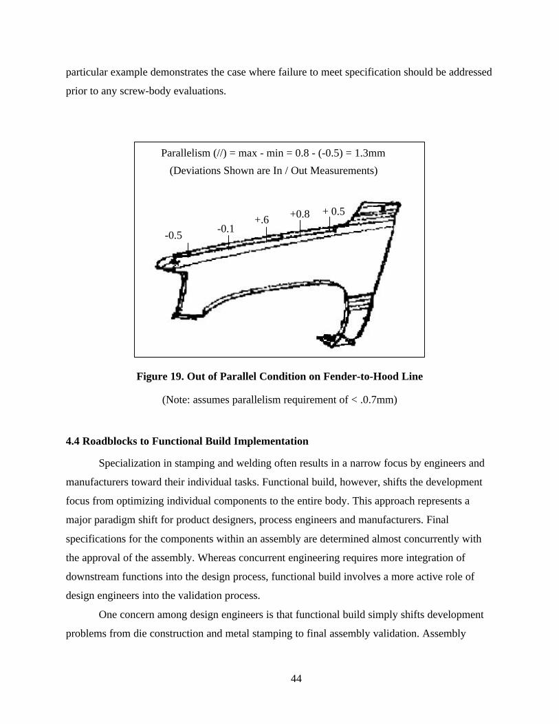
44
particular example demonstrates the case where failure to meet specification should be addressed
prior to any screw-body evaluations.
(Deviations Shown are In / Out Measurements)
Parallelism (//) = max - min = 0.8 - (-0.5) = 1.3mm
-0.5-0.1
+.6 +0.8 + 0.5
Figure 19. Out of Parallel Condition on Fender-to-Hood Line
(Note: assumes parallelism requirement of < .0.7mm)
4.4 Roadblocks to Functional Build Implementation
Specialization in stamping and welding often results in a narrow focus by engineers and
manufacturers toward their individual tasks. Functional build, however, shifts the development
focus from optimizing individual components to the entire body. This approach represents a
major paradigm shift for product designers, process engineers and manufacturers. Final
specifications for the components within an assembly are determined almost concurrently with
the approval of the assembly. Whereas concurrent engineering requires more integration of
downstream functions into the design process, functional build involves a more active role of
design engineers into the validation process.
One concern among design engineers is that functional build simply shifts development
problems from die construction and metal stamping to final assembly validation. Assembly

45
manufacturers and process engineers argue that if stamping plants would produce parts at
nominal, then they could more efficiently validate their tooling. Even proponents of functional
build certainly agree that greater conformance of stamping dimensions to specification is
desirable. Proponents, however, recognize that once manufacturing processes are constructed,
drawing changes to design prints or minor modifications to assembly tooling locators may be
less expensive than physically reworking tools. Functional build does not imply that the original
design would not produce a high quality body, rather that components with small mean
deviations also may lead to the desired result. Thus, a basic tenet for functional build success is a
commitment from product engineering, stamping and assembly to work toward improving the
overall vehicle development process and not necessarily optimizing an individual activity.
Another area of contention with the functional build (FB) process is the usefulness of
constructing the first screw-body using die source tryout parts. Table 14 lists several benefits and
concerns with constructing the first screw-body. These findings suggest that although the
functional build process has many benefits including lower die rework costs, some concerns
remain regarding functional build’s ability to reduce time.
Benefits Main Concerns
Provides system to approve out-specificationcomponent dimensions, saving die rework.
Certain problem parts (e.g., body sides, quarterouters, fenders) may require many evaluations.
Dimensions approved out-of-specification arerarely rejected at home line.
If parts are not in dimensional window, highlikelihood of failure.
Enables manufacturers to identifying problemsnot captured in the measured dimensional data.
Parts change from die source to home line.
Enables manufacturers to eliminate and/or re-classify dimensions as less important.
Cost and time to conduct FB. Evaluationsrequire tryout resources.
Identify potential build issues for in-specification dimensions (design errors).
Lack of support for the FB process from thoseresisting organizational change.
Identify datum and fixture problems
Table 14. Benefits and Concerns of FB#1
Some manufacturers also are unsure whether to use functional build as a “formal” buyoff
process or merely as an input to the die shipment decision process. Under a formal “buyoff”
process, components not approved at the first functional build would require re-submittal for
approval. The benefit of this approach is that it requires die shops and release engineers to make

46
the changes requested by the functional build team. The tradeoff with this approach is the extra
time necessary to perform multiple evaluations prior to shipping dies. For this reason, several
manufacturers view the first functional build as a “one-shot” system.
Another approach to functional build that subscribes to the “one-shot” system is to view
the overall functional build approach as a narrowing process. Manufacturers set goals not based
on the percentage of components accepted at a functional build event, but rather the percentage
of dimensions either in-specification or approved out-specification. Under the latter,
manufacturers set goals for various stages. For example, they may want 80% of their stamping
dimensions in-specification prior to the first functional build event. They would then expect to
conditionally approve another 10% through the first functional build event. By the end of the
second functional build (components in the home line), they might expect to have 95-98% of the
dimensions accepted either in-specification or through tolerance revisions. The remaining
dimensions then are resolved during the weld validation process by either reworking dies or
assembly tooling. The strategy here is to view functional build as a system for the continuous
resolution of problems.

47
5.0 Event Based Functional Build
This section recommends a dimensional evaluation process for event-based functional
build. Figure 20 lists several key dimensional evaluation events and approximate timing
guidelines. This hypothetical program is based on meeting a 24-month or 104 week timing
objective. This further assumes a 52-week time frame from die source tryout to start of
production (note: the other 52-week time frame is for design and construction). Of course, actual
timing would certainly vary by manufacturer and a particular car program.
Figure 20 separates the overall process into three validation phases: die-source tryout,
press shop tryout (home line) and body shop tryout. Note that many events overlap due to the
status of individual components. For example, if a manufacturer accepts the front pillar
reinforcement in the first screw-body build but rejects the body side, then the front pillar dies
may be shipped to the press shop while modifications on the body side occur at the die source.
Under event-based functional build, the screw-body build events must occur on time.
Therefore, at the time of a scheduled build, if a particular component is not meeting its
dimensional objectives or not updated to its most recent engineering change level, then the event
must occur with non-conforming products. Under this approach, manufacturers delay changes
until the modification period after the event rather than miss a timing deadline. For some
problem parts, they may need to execute special recovery plans to insure that components meet
the next event objectives. Obviously, using non-conforming product diminishes the value of the
screw-body build, but meeting timing objectives is sacred under event-based functional build.

48
Figure 20. Timing Process

49
5.1 Die Source Tryout
To validate dimensional conformance at the die source, an iterative process of five-panel
dimensional studies is recommended, which examines mean conformance relative to nominal.
The purpose of functional build submittal criteria is to insure a high likelihood of approving the
part dimensionally. In this situation, the functional build team’s primary role is to (1) evaluate
those dimensions in the dimensional gray area, (2) identify any potential build concerns such as
short trim on a weld flange and (3) identify any design errors. Of course, an effective prototype
process strongly minimizes the need for identifying design errors. Figure 21 proposes a
dimensional validation process at the die source for parts classified as functional build parts.
Run5 pc Study
Ship Dies
Reject
Conduct Screwbody#1
Conditional ApproveStamped Part inScrewbody #1
MakeCorrections
Yes
NoMeet Timing and/or
Dimensional Criteria?
Dimensional Criteria• 80% Mean Within Specification• Range < 1mm
Make corrections for:• screwbody concerns • late engineering changes• known problems
Run 5 pc Study
Verify Changes
Die Source Tryout
Figure 21. Die Source Tryout Process Flow
50
Under these proposed criteria, manufacturers potentially could approve a dimension with
a mean equal to the specification limit. (Note approximately half the samples would be out of
specification is this situation). Historical evidence, however, suggests that assembly processes
usually may compensate for dimensions meeting all of these proposed criteria. This study asserts
that the potential savings in lead-time and rework costs far out-weigh the additional risk of later
rework to insure that 100% of the sample panels are within the original specifications. In two
functional build case studies, no instances existed where a dimension with a mean in
specification later required rework to fix an assembly problem.
5.2 Production Source Tryout Process
Figure 22 recommends a flow chart for production source tryout (press shop). A common
evaluation process is recommended for home line tryout regardless of the part categorization
(functional build and non-functional build parts). According to this process, the existing practice
of conducting multiple die sets for process validation should continue. For scheduling issues,
manufacturers typically should limit the time in a press for a tryout run to no more than 4 hours.
The dimensional evaluation process at home line tryout should be aimed at four primary
objectives:
1. Insure that stamped parts are capable within a stamping run (meet CR requirements),
2. Insure that the stamping facility demonstrates an ability to establish a stable mean
between die sets (i.e. control mean shifts between die sets),
3. Insure that a quality assembly (all assembly dimensions within specification) is feasible
given the stamping mean deviations and
4. Finalize production mean targets and tolerances for stamped components.
The significant differences between this proposed approach and the PPAP recommended
approach are additional criteria on the control of the mean between runs, and the elimination of
Cpk as the part approval criteria. With the elimination of Cpk, this approach requires that the
functional build and assembly validation teams verify that the stamping mean deviations (once
they are shown stable) may produce dimensionally correct sub-assemblies. Inherent in this

51
assumption is the responsibility of assembly buyoff teams to make any necessary adjustments to
produce a good assembly. In other words, adjusting the assembly process to correct an out-of-
specification condition usually is preferred over reworking a stamping die if either action
resolves the problem.
Home Line Trial #1Measure 5 pc Study
Home Line Trial #2Measure 30/100 pc Study
ConductScrewbody #2
Approve Part for ProductionEstablish Production Target Mean
Establish Production Specifications
RejectMake Corrections
Run 5 pc Study
AcceptPart?
MeetAcceptanceCriteria?*
Yes No
* Stamping Acceptance CriteriaVariation -- Cp > 1.33Mean -- Capable of Producing Acceptable Subassembly
Figure 22. Press Shop Tryout
Another modification to the current process is a requirement that demonstrates the ability
to setup dies repeatedly without significant mean shifts. It is recommended to require that all
dimensions exhibit mean shifts less than 0.5mm across repeated die sets. Although this
requirement may create additional stamping runs during secondary tryout, compliance insures
52
that the functional build process is evaluating representative panels and that stamping plants have
their processes in-control for regular production.
The results of this study also support a reduction in sample size for the PPAP run. PPAP
requires a measured sample of 100 out of a run of 300. This study recommends a sample of 30
from a run of 100. Historical evidence suggests that measuring large samples from a single run is
resource intensive and provides minimum value. Moreover, relatively few dimensions (an
estimate of 2 to 4%) would be affected by reducing the sample size to 30. However, the savings
in inspection costs and timing for decision-making offset the additional risk.
53
6.0 The Future of Functional Build
This report presents a new paradigm for body validation. Manufacturers that continue to
embrace new methodologies and business practices not only will remain competitive in the
global market but also set the benchmark for competition. By using an integrated validation
approach like functional build, manufacturers may accelerate the product development life cycle
while saving costs in manufacturing process development.
An important issue facing functional build manufacturers is its future application.
Functional build involves an additional validation step to construct screw-body prototypes and it
requires greater coordination between development functions. Several manufacturers using
functional build hope they will eventually develop the manufacturing knowledge necessary to
identify when rework is value-added without having to construct screw-body prototype
assemblies. The goal is to replace these prototypes with process simulation or math-based
functional build. Even with this approach, two fundamental principles behind functional build
will remain. First, manufacturers should never rely solely on statistical indices to make tooling
and validation decisions. Incorporating process knowledge with dimensional data results in more
effective decisions than those based purely on quantitative results. Second, development
functions must integrate their product/process knowledge, and focus on the final customer
product and not necessarily individual components.
Related Documents