Evaluation on Impulse Bit Characteristics of Pulsed Plasma Thruster by Single Impulse Measurement IEPC-2005-236 0 = J = O) = A = i = (7 = 1. = O~ = TO = T = Junpei Iio*, Junji Uezu,* and Tadanori Fukushima* To/~'o Metropolitan INstitute of Technology (preseNffy To/~'o Metropolitan UNiversi~ HiNo 6-6, To@o, 191-OOG.~, Japan and Yukiya Kamishima* and Haruki Takegaharar To/c~'o Metropolitan UNiversi¢ hriNo 6-6, To/c~'o, 191-0065, Japan Abstract: Pulsed Plasma Thruster (PPT) is one of the promising electric propulsion devices for the small satellite as the following advantages: simplicity, lightweight, robustness, and low power consumptions. Moreover PPT can generate a very small impulse bit with high specific impulse at optional time interval. Therefore PPT has great advantages as a precision attitude control system. In such system, the thrust characteristics such as the thrust vector and the shot variation must be measured before mounted on the actual satellite. However, the measurement of the impulse bit by a single pulse is very difficult with the target pendulum method, because PPT generates a very small impulse bit. Therefore, in this study, we employed a torsion-type thrust stand which has the following three advantages; 1) by employing a C-section pipe as its pivot axis, high resolution of 200 nN-s was achieved, 2) by mounting a stepping motor on the thrust stand, changing the mounting angle of thruster head by 1.8 degree/step was possible from outside of the vacuum chamber, 3) by using the impulse generator (an electromagnetic coil), the calibration and the damping was possible in the vacuum camber. Using this thrust stand, measurement of impulse bit of our designed parallel-plate type PPT (PPT-B20) was possible at a single pulse. As a result, it was obtained that the deflection angle of the thrust vector against the primary axis was less than three degree, and the shot variation was within _+10% of the average impulse bit. Nomenclature distance of the PPT from the pivot axis distance of the displacement sensor (LVDT) from the thrust stand pivot axis distance of the counter weight from the pivot axis displacement angle, mounting angle of the thruster head moment inertia of the thrust stand damping coefficient of the thrust stand angular frequency of the thrust stand amplitude of thrust stand and displacement sensor (LVDT) Impulse bit pulsed current into the coil standard deviation magnitude of thrust vector deflection angle of thrust vector averaged impulse bit at the mounting angle of 0 maximum impulse bit of TO * Graduate Student, Department of Aerospace Engineering, [email protected] r Professor, Department of Aerospace Engineering, [email protected] - 1 -

Welcome message from author
This document is posted to help you gain knowledge. Please leave a comment to let me know what you think about it! Share it to your friends and learn new things together.
Transcript
Evaluation on Impulse Bit Characteristics
of Pulsed Plasma Thruster
by Single Impulse Measurement
I E P C - 2 0 0 5 - 2 3 6
0 = J =
O ) =
A =
i = ( 7 =
1. = O~ =
TO = T =
Junpei Iio*, Junji Uezu,* and Tadanori Fukushima*
To/~'o Metropolitan INstitute o f Technology (preseNffy To/~'o Metropolitan UNivers i~
HiNo 6-6, To@o, 191-OOG.~, Japan
and
Yukiya Kamishima* and Haruki Takegahara r
To/c~'o Metropolitan UNiversi¢ hriNo 6-6, To/c~'o, 191-0065, Japan
A b s t r a c t : Pulsed Plasma Thruster (PPT) is one of the promising electric propulsion
devices for the small satellite as the following advantages: simplicity, lightweight, robustness, and low power consumptions. Moreover PPT can generate a very small impulse bit with high specific impulse at optional time interval. Therefore PPT has great advantages as a precision atti tude control system. In such system, the thrust characteristics such as the thrust vector and the shot variation must be measured before mounted on the actual satellite. However, the measurement of the impulse bit by a single pulse is very difficult with the target pendulum method, because PPT generates a very small impulse bit. Therefore, in this study, we employed a torsion-type thrust stand which has the following three advantages; 1) by employing a C-section pipe as its pivot axis, high resolution of 200 nN-s was achieved, 2) by mounting a stepping motor on the thrust stand, changing the mounting angle of thruster head by 1.8 degree/step was possible from outside of the vacuum chamber, 3) by using the impulse generator (an electromagnetic coil), the calibration and the damping was possible in the vacuum camber. Using this thrust stand, measurement of impulse bit of our designed parallel-plate type PPT (PPT-B20) was possible at a single pulse. As a result, it was obtained that the deflection angle of the thrust vector against the pr imary axis was less than three
degree, and the shot variation was within _+10% of the average impulse bit.
Nomenclature
distance of the PPT from the pivot axis distance of the displacement sensor (LVDT) from the thrust stand pivot axis distance of the counter weight from the pivot axis displacement angle, mounting angle of the thruster head moment inertia of the thrust stand damping coefficient of the thrust stand angular frequency of the thrust stand amplitude of thrust stand and displacement sensor (LVDT) Impulse bit pulsed current into the coil standard deviation magnitude of thrust vector deflection angle of thrust vector averaged impulse bit at the mounting angle of 0 maximum impulse bit of T O
* Graduate Student, Department of Aerospace Engineering, [email protected] r Professor, Department of Aerospace Engineering, [email protected]
- 1 -
I. Introduction
In 1964, Pulsed Plasma Thruster (PPT) was for the first time employed as an electric propulsion device on the satellite. Since then, PPT has been the promising candidate by the following characteristics:
1) Simplicity: By employing the solid propellant, PPT system does not need tankages, seals and mechanical valves.
2) Lightweight and High reliability: PPT system has only two power supplies for the thrust generation; one is the capacitor charge power supply and the other is the ignition power supply. Also then, the system has only one moving mechanical parts that are mechanism is feeding the solid propellant into the discharge chamber.
3) Precise total impulse: PPT generates a pulsed thrust (Impulse Bit) at optional time, and generates repetitive thrust at the optional time interval. Therefore, PPT can generate and control the discrete total impulse.
PPT has been expected to be adopted missions 1,2, such as the attitude control, the precise pointing, the drag compensation, the orbit changing and the formation flying. Therefore, in Tokyo Metropolitan Institute of Technology (TMIT), some types of PPT have been researched and developed, and succeeded in generating the wide range of impulse bit (20/~Ns - 2ruNs) with low power consumptions (-20W), small in size (less than A5 paper size) and structure weight (less than 2 kg) 3.
The great difference from other propulsion devices is the controllable and precise total impulse by accumulating a small impulse bit. However, the impulse bit has uncertainty by shot variation and deflection angle of thrust vector. Concerning the PPT integration to a satellite, the shot variation and the thrust vector must be investigated and evaluated before the mount on a satellite.
II. Objectives The objectives of this study are investigations and evaluations on the shot variation and the thrust vector of PPT-
B20, by using the new high-resolution torsion-type thrust stand.
III. Experimental Facilities and Procedure
A. Test Thruster
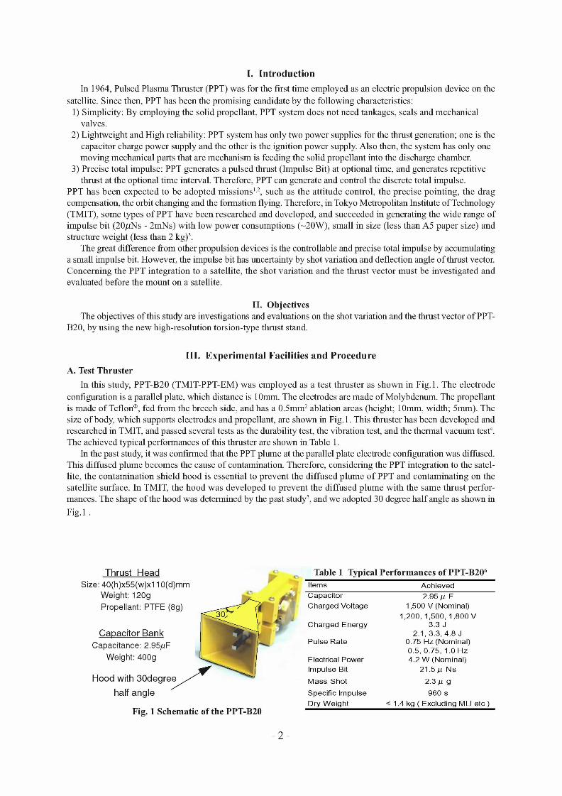
In this study, PPT-B20 (TMIT-PPT-EM) was employed as a test thruster as shown in Fig. 1. The electrode configuration is a parallel plate, which distance is 10ram. The electrodes are made of Molybdenum. The propellant is made of Teflon ®, fed from the breech side, and has a 0.5ram 2 ablation areas (height; 10ram, width; 5ram). The size of body, which supports electrodes and propellant, are shown in Fig. 1. This thruster has been developed and researched in TMIT, and passed several tests as the durability test, the vibration test, and the thermal vacuum test 4. The achieved typical performances of this thruster are shown in Table 1.
In the past study, it was confirmed that the PPT plume at the parallel plate electrode configuration was diffused. This diffused plume becomes the cause of contamination. Therefore, considering the PPT integration to the satel- lite, the contamination shield hood is essential to prevent the diffused plume of PPT and contaminating on the satellite surface. In TMIT, the hood was developed to prevent the diffused plume with the same thrust perfor- mances. The shape of the hood was determined by the past study 5, and we adopted 30 degree half angle as shown in
Fig. 1.
Thrust Head
Size: 40(h)x55(w)x110(d)mm Weight: 120g
Propellant: PTFE (8g)
Capac i to r Bank
Capacitance: 2.95/~F
Weight: 400g
Hood with 30degree~ half angle
Fig. 1 Schematic of the PPT-B20
Table 1 Typical Performances of PPT-B206 Items Achieved Capacitor 2.95 ,u F Charged Voltage 1,500 V (Nominal)
1,200, 1,500, 1,800 V Charged Energy 3.3 J
2.1,3.3, 4.8 J Pulse Rate 0.75 Hz (Nominal)
0.5, 0.75, 1.0 Hz Electrical Power 4.2 W (Nominal) Impulse Bit 21.5 # Ns
Mass Shot 2.3 # g
Specific Impulse 960 s Dry Weight < 1.4 kg ( Excluding MLI etc )
-2-
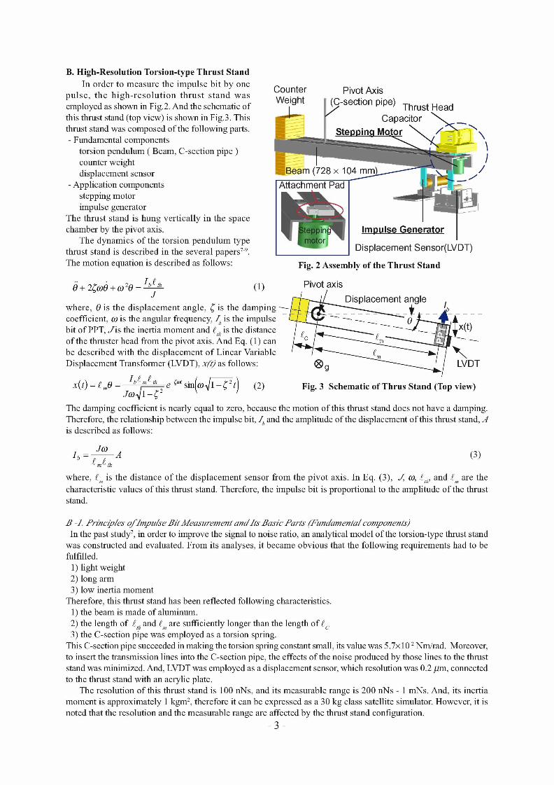
B. High-Resolution Torsion-type Thrust Stand In order to measure the impulse bit by one
pulse, the high-resolut ion thrust stand was employed as shown in Fig.2. And the schematic of this thrust stand (top view) is shown in Fig.3. This thrust stand was composed of the following parts. - Fundamental components
torsion pendulum ( Beam, C-section pipe ) counter weight displacement sensor
- Application components stepping motor impulse generator
The thrust stand is hung vertically in the space chamber by the pivot axis.
The dynamics of the torsion pendulum type thrust stand is described in the several papers 7 9. The motion equation is described as follows:
Counter Weight
Attachment Pad
Pivot Axis
[~ -section pipe) Thrust Head Capacitor ~ _ ~
\
/ /
p*
Impulse Generator
Displacement Sensor(LVDT)
Fig. 2 Assembly of the Thrust Stand
+ 2~o0 + ( . 0 2 0 - IS'h (1) ,/Piv°t axis J Displacement angle
where, 0 is the displacement angle, ~ is the damping ~ - _ L - 4 - / - ~ ~ ~ , coefficient, go is the angular frequency,/a is the impulse bit of PPT, J i s the inertia moment and g,a is the distance of the thruster head from the pivot axis. And Eq. (1) can be described with the displacement of Linear Variable Displacement Transformer (LVDT), x(7) as follows: kVDT
ISm~th e~°*sin[~o'~l-~t) (2) Fig. 3 Schematic of Thrus Stand (Top view) X( t) = ~mO -- jo.)~'~-'~2
The damping coefficient is nearly equal to zero, because the motion of this thrust stand does not have a damping. Therefore, the relationship between the impulse bit, ~ and the amplitude of the displacement of this thrust stand, ~4 is described as follows:
Jo) I b - A (3)
where, g is the distance of the displacement sensor from the pivot axis. In Eq. (3), J, go, gt~, and g are the characteristic values of this thrust stand. Therefore, the impulse bit is proportional to the amplitude of the thrust stand.
B H. Principles oflmpulxe Bit Measurement andltx Basic Parts (Fundamental components) In the past study 7, in order to improve the signal to noise ratio, an analytical model of the torsion-type thrust stand
was constructed and evaluated. From its analyses, it became obvious that the following requirements had to be fulfilled.
1) light weight 2) long arm 3) low inertia moment
Therefore, this thrust stand has been reflected following characteristics. 1) the beam is made of aluminum. 2) the length of gt~ and g are sufficiently longer than the length ofg c 3) the C-section pipe was employed as a torsion spring.
This C-section pipe succeeded in making the torsion spring constant small, its value was 5.7×10² Nm/rad. Moreover, to insert the transmission lines into the C-section pipe, the effects of the noise produced by those lines to the thrust stand was minimized. And, LVDT was employed as a displacement sensor, which resolution was 0.2/,tin, connected to the thrust stand with an acrylic plate.
The resolution of this thrust stand is 100 nNs, and its measurable range is 200 nNs - 1 ruNs. And, its inertia moment is approximately 1 kgm 2, therefore it can be expressed as a 30 kg class satellite simulator. However, it is noted that the resolution and the measurable range are affected by the thrust stand configuration.
- 3 -
27 -2. Equipments f o r Thrust Vector Measurement and Calibration (~4pp/ication components)
27 -2 -a. Thruster Rotation Motor The stepping motor is mounted on the tip of the thrust stand as shown in Fig.2. It can easily change the mounting
angle by the step of 1.8 ° from outside of the chamber, with keeping the space chamber at low pressure condition. PPT thruster head and capacitors are mounted on the attachment pad. The attachment pad is connected to the thrust stand with the rotational axis of the stepping motor.
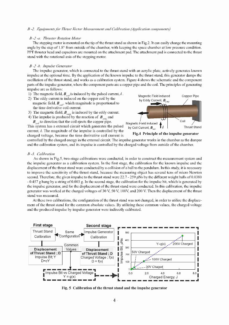
27 -2 -b. Impu/se Generator The impulse generator, which is connected to the thrust stand with an acrylic plate, actively generates known
impulse at the optional time. By the application of the known impulse to the thrust stand, this generator damps the oscillation of the thrust stand, and works as a calibration system. Figure 4 shows the schematic and the component parts of the impulse generator, where the component parts are a copper pipe and the coil. The principles of generating impulse are as follows: 1) The magnetic field, B o,~is induced by the pulsed current, i . Magnetic Field induced Copper Pipe 2) The eddy current is induced on the copper coil by the
magnetic field, B o,~, which magnitude is proportional to the time derivative coil current.
3) The magnetic field, Bd~y is induced by the eddy current. 4) The impulse is produced by the reaction of Bd~y and
Boi/to direction that the coil ejects the copper pipe. Magnetic This system has a external circuit which generates the pulsed b y C o i l , _ ~o,,
current, i. The magnitude of the impulse is controlled by the charged voltage, because the time derivative coil current is Fig.4 Principle of the impulse generator
controlled by the charged energy in the external circuit. The impulse generator works in the chamber as the damper and the calibration system, and its impulse is controlled by the charged voltage from outside of the chamber.
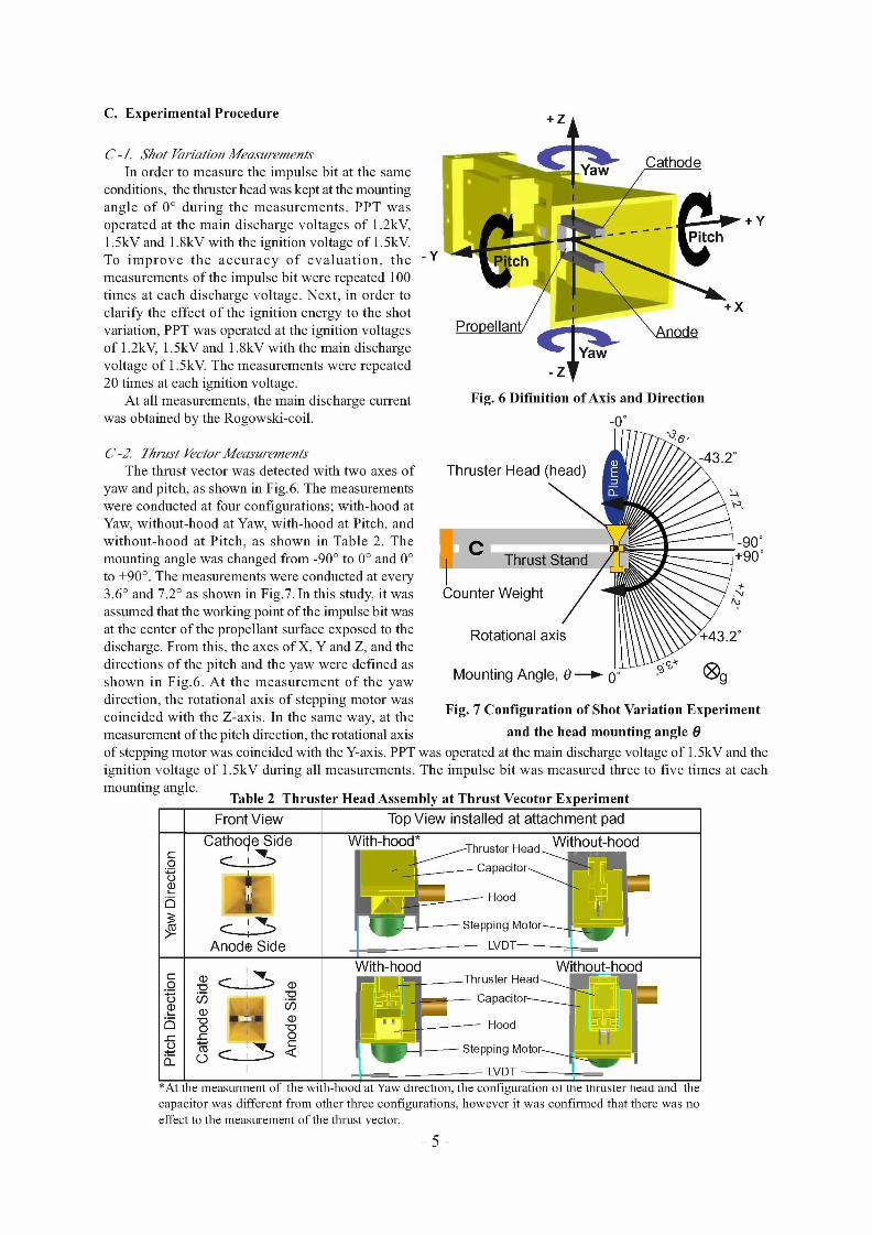
27 -3. Cal/brat/on As shown in Fig.5, two-stage calibrations were conducted, in order to construct the measurement system and
the impulse generator as a calibration system. In the first stage, the calibration for the known impulse and the displacement of the thrust stand were conducted by a collision of a ball to the pendulum. In this study, it is necessary to improve the sensitivity of the thrust stand, because the measuring object has several tens of micro Newton second. Therefore, the given impulse to the thrust stand were 22.7 - 259/~Ns by the different weight balls of 0.0380 - 0.457 g hung by a string of 0.003 g. In the second stage, the calibration for the impulse bit, which is generated by the impulse generator, and for the displacement of the thrust stand were conducted. In this calibration, the impulse generator was worked at the charged voltages of 30 V, 50 V, 100V, and 200 V. Then the displacement of the thrust stand was measured.
At these two calibrations, the configuration of the thrust stand was not changed, in order to utilize the displace- ment of the thrust stand for the common absolute values. By utilizing these common values, the charged voltage and the produced impulse by impulse generator were indirectly calibrated.
First stage Thrust Stand
Calibration
Displacement Values [ Displacement | ~a 300 50V Charged , . ,"" " °fThrustStand;D i ofThrustStand;D I ~ 2oo /
Impulse Bit;Y Charged Voltage ;f(x) I loo .m "~00vcha rged
D=oY D = f(x) I -- ~ 30V ChaFed, I I I I
I ~pp u~se~it=vs Charged Vo l tagg l l ILk . | 0'0.0 2.0 4.0 6.0 Y = g(x) ~ - - - - ' I ~ 1
I- . . . . . . . . . d
Same _.~lmpulse Generator I 500 C°nfigurati°n "I Calibrati°n I I
Common II ~L400 "" " " " Y=g(x) oo'" 200V Charged
Second stage I p m m m m m m m m m m m m m m - l l I I I I I I I I
8.0 I Charged Energy, J Ik . . . . . . . . . . . . . . =11
Fig. 5 Calibration of the thrust stand and the impulse generator
- 4 -
C. Experimental Procedure .
C-/ . Shot ~r/at /on Measurements In order to measure the impulse bit at the same
conditions, the thruster head was kept at the mounting angle o f 0 ° during the measurements . PPT was operated at the main discharge voltages o f 1.2kV, 1.5kV and 1.8kV with the ignition voltage o f 1.5kV. To i m p r o v e the a c c u r a c y o f e va l ua t i on , the measurements o f the impulse bit were repeated 100 times at each discharge voltage. Next, in order to clarify the effect o f the ignition energy to the shot variation, PPT was operated at the ignition voltages o f 1.2kV, 1.5kV and 1.8kV with the main discharge voltage o f 1.5kV. The measurements were repeated 20 times at each ignition voltage.
At all measurements, the main discharge current was obtained by the Rogowski-coil.
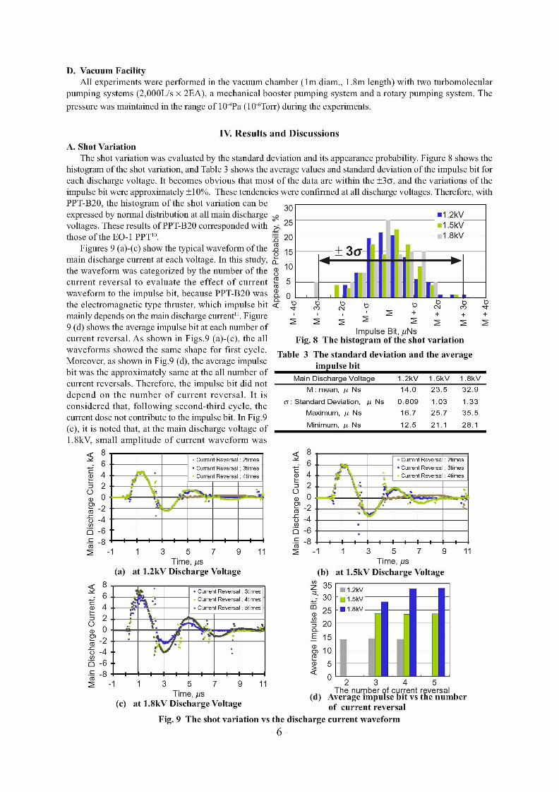
C-2. Thrust Kector Measurements The thrust vector was detected with two axes o f
yaw and pitch, as shown in Fig.6. The measurements were conducted at four configurations; with-hood at Yaw, without-hood at Yaw, with-hood at Pitch, and wi thout -hood at Pitch, as shown in Table 2. The mounting angle was changed from -90 ° to 0 ° and 0 ° to +90 ° . The measurements were conducted at every 3.6 ° and 7.2 ° as shown in Fig.7. In this study, it was assumed that the working point o f the impulse bit was at the center o f the propellant surface exposed to the discharge. From this, the axes o f X, Y and Z, and the directions o f the pitch and the yaw were defined as shown in Fig.6. At the measurement o f the yaw direction, the rotational axis o f stepping motor was coincided with the Z-axis. In the same way, at the measurement of the pitch direction, the rotational axis
- y
~ + Y
~X
Fig. 6 Difinition of Axis and Direction
_0 °
"86,o
Thruster Head ( h e a d ) ~ . 2 , ~
C -90° . Thrust S 0°
Counter Weight
Rotational axis ///\\\~Y+43.2°
Mounting Angle, 0 ~ 0 o ,Og
Fig. 7 Configuration of Shot Variation Experiment
and the head mounting angle 0
of stepping motor was coincided with the Y-axis. PPT was operated at the main discharge voltage o f 1.5kV and the ignition voltage o f 1.5kV during all measurements. The impulse bit was measured three to five times at each mounting angle.
Table 2 Thruster Head Assembly at Thrust Vecotor Experiment
Front View
Cathoc~e Side
a
<_:2> Anode Side
Top View installed at attachment pad J-Thruster Head Without-hood With-h°°d*/j~ ~ ~
l ~ Capacitor~ ~ ~ Hood
l Stepping Motor--~-~ ~ ]
= =~_____----------- LVDT--------~= With-hood Without-hood , - i ra , - . Thruster Head ~ ~
~ ~.~-.~ ~ ~ l : ~ Capacitor~ ~ ~ ~ ~ Hood i5 o o "1 ("' "~ 0 "~ ~ 1 <~ ! ~ S t e p P ~ v ~ M ° t ° r ~ ~ |
*At the measurment of the with-hood at Yaw direction, the configuration ot me thruster head and the capacitor was different from other three configurations, however it was confirmed that there was no effect to the measurement of the thrust vector.
-5-
D. Vacuum Facility All experiments were performed in the vacuum chamber ( lm diam., 1.8m length) with two turbomolecular
pumping systems (2,000L/s × 2EA), a mechanical booster pumping system and a rotary pumping system. The
pressure was maintained in the range of 104pa (106Torr) during the experiments.
IV. Results and Discuss ions
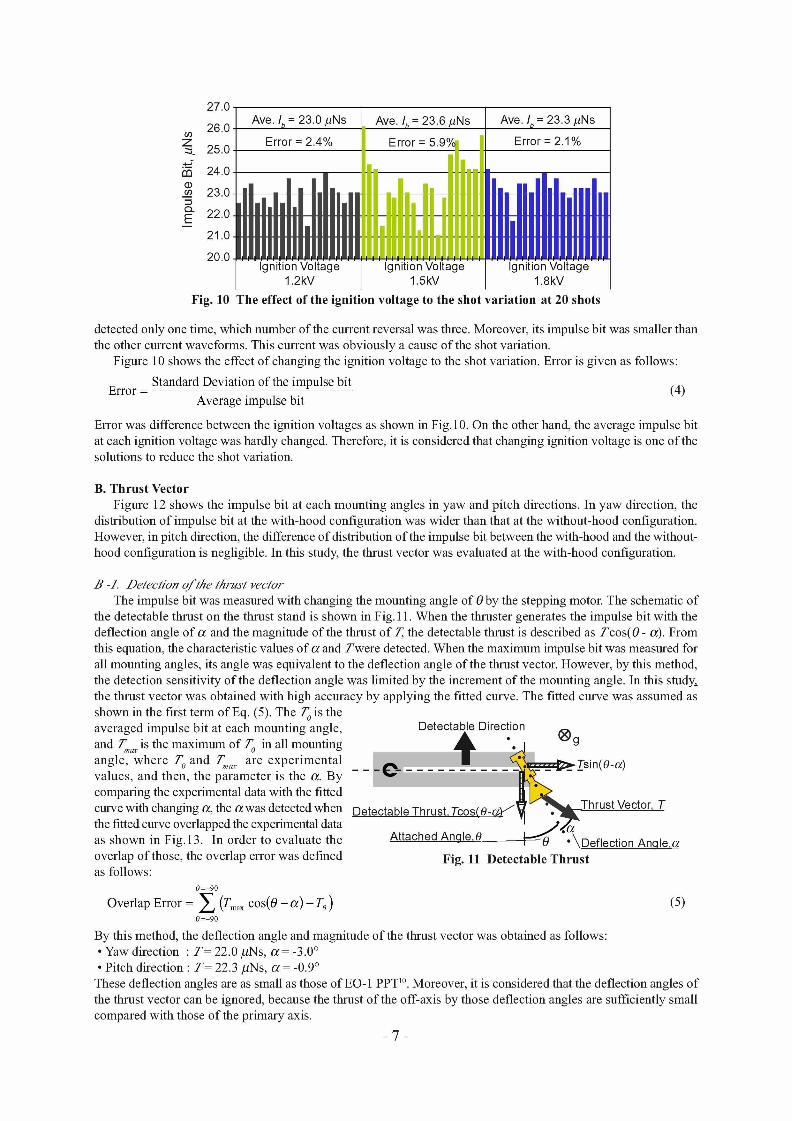
A. Shot Variation The shot variation was evaluated by the standard deviation and its appearance probability. Figure 8 shows the
histogram of the shot variation, and Table 3 shows the average values and standard deviation of the impulse bit for each discharge voltage. It becomes obvious that most of the data are within the +3eL and the variations of the impulse bit were approximately + 10%. These tendencies were confirmed at all discharge voltages. Therefore, with PPT-B20, the histogram of the shot variation can be expressed by normal distribution at all main discharge voltages. These results of PPT-B20 corresponded with those of the EO-1 PPT 1°.
Figures 9 (a)-(c) show the typical waveform of the main discharge current at each voltage. In this study, the waveform was categorized by the number of the current reversal to evaluate the effect o f current waveform to the impulse bit, because PPT-B20 was the electromagnetic type thruster, which impulse bit mainly depends on the main discharge current 11 . Figure 9 (d) shows the average impulse bit at each number of current reversal. As shown in Figs.9 (a)-(c), the all waveforms showed the same shape for first cycle. Moreover, as shown in Fig.9 (d), the average impulse bit was the approximately same at the all number of current reversals. Therefore, the impulse bit did not depend on the number of current reversal. It is considered that, following second-third cycle, the current dose not contribute to the impulse bit. In Fig.9 (c), it is noted that, at the main discharge voltage of 1.8kV, small amplitude of current waveform was
8 - 6 t - O 4 L- = 2 O ¢ 0 2 - 2
-~-4 (t) ~ - 6 .IC. - 8
5
o
(t) k5
" ~ • Current Reversal ; 2times
• Current Reversal ; 3times
" ; - " ' Current Reversal ; 4times • X
_ _ / '
(a) 8 6 4 2 0
-2 -4 -6 -8
-1
1 3 5 7 9 Time,/~s
at 1.2kV Discharge Voltage
11
3O
25
00 -8 15 ct o¢ 10 i
13-
I1.2kV l 1:5 v 1
1.1!i D D D D D D D D
, ~ + I I I -I- .I. -i-
Impulse Bit,/JNs Fig. 8 The histogram of the shot variation
Table 3 The standard deviation and the average impulse bit
Main Discharge Voltage 1.2kV 1.5kV 1 .SkY M : mean, ,u Ns 14 .0 2 3 . 5 3 2 . 9
e; : S tandard Deviat ion, ,u Ns 0 . 8 0 9 1 .03 1 .33
Max imum, ,u Ns 16 .7 2 5 . 7 3 5 . 5
Min imum, # Ns 12 .5 21.1 28.1
5 c-
L_
o
t~
(I)
t~
68 J • Current Reversal; 2times
~ • Current Reversal; 3times
4 ~"~;-~>* Current Reversal; 4hmes
" ¢ I . , ~ . . . . J . . . . . . . } • , • * u,
-2 &. ~ "- - 4 •
-6 - 8
-1 1 3 5 7 9 11 Time,/~s
at 1.5kV Discharge Voltage (b)
E~ " , C t R . . . . . . . . . . . I ; 3times ~L35[ II 1.2kv
.~ Current Reversal; 4times - 30 [ ] 1 . 5 k V
, ° c . . . . . t R . . . . . . I ; 5times ~0 2 5 • 1 8 k V • *
r - - E 15
." • e g l o 5
o 1 3 5 7 9 11 2 3 4 5
The number of current reversal Time, ~s (d) Average impulse bit vs the number
(c) at 1.8kV Discharge Voltage of current reversal
Fig. 9 The shot variation vs the discharge current waveform
- 6 -
27.0
:~ 26.0
25.0
24.0 03 oo 23.0
22.0
21.0
t Ave_~-23.0/~N. s ], Ave./~=23.6/~Ns Ave. /b = 23.3 /~Ns
Error = 2.4% Error = 5.9%. !/ Error = 2.1%
,. __I" i : . . . . . I I ,_ , ,_If , l_ ,,,I__
IIIIIIIIIIIIIIIIIIII : : i i, :i ill[i i ill ii i I M I I I M I I I I I I I ' I~irii{ibhVdl}fg6 . . . . . . I'~ir~i{ibh'~'dl}&ge''' ] ' ' ' i~irii{ibh'Vdl{fig6" ' '
1.2kV 1.5kV 1.8kV Fig. 10 The effect of the ignition voltage to the shot variation at 20 shots
detected only one time, which number of the current reversal was three. Moreover, its impulse bit was smaller than the other current waveforms. This current was obviously a cause of the shot variation.
Figure 10 shows the effect of changing the ignition voltage to the shot variation. Error is given as follows:
Standard Deviation of the impulse bit Error = (4)
Average impulse bit
Error was difference between the ignition voltages as shown in Fig. 10. On the other hand, the average impulse bit at each ignition voltage was hardly changed. Therefore, it is considered that changing ignition voltage is one of the solutions to reduce the shot variation.
B. Thrust Vector Figure 12 shows the impulse bit at each mounting angles in yaw and pitch directions. In yaw direction, the
distribution of impulse bit at the with-hood configuration was wider than that at the without-hood configuration. However, in pitch direction, the difference of distribution of the impulse bit between the with-hood and the without- hood configuration is negligible. In this study, the thrust vector was evaluated at the with-hood configuration.
27 -]. Detection o f the thrust vector The impulse bit was measured with changing the mounting angle of 0 by the stepping motor. The schematic of
the detectable thrust on the thrust stand is shown in Fig. 11. When the thruster generates the impulse bit with the deflection angle of a and the magnitude of the thrust of T,, the detectable thrust is described as Tcos(0 - a). From this equation, the characteristic values of a and Twere detected. When the maximum impulse bit was measured for all mounting angles, its angle was equivalent to the deflection angle of the thrust vector. However, by this method, the detection sensitivity of the deflection angle was limited by the increment of the mounting angle. In this study~ the thrust vector was obtained with high accuracy by applying the fitted curve. The fitted curve was assumed as shown in the first term of Eq. (5). The T O is the averaged impulse bit at each mounting angle, and 7~,~ is the maximum of TO in all mounting angle, where T o and 7~,~, x are experimental values, and then, the parameter is the a. By comparing the experimental data with the fitted curve with changing a, the awas detected when the fitted curve overlapped the experimental data as shown in Fig. 13. In order to evaluate the overlap of those, the overlap error was defined as follows:
0 +90
Overlap Error = 2 (T ..... cos(0 - a ) - T o) 0 9O
Detectable Direction ®° - - - C - " -~- "'2~ . ~ ~ - T s i n ( 0 - ~ z )
II I . , ~ Detectable Thrust, Tcos(O-q,Y/'~V~• Thrust Vector, T
' ~ ' ~ 0 " ? Deflection Anqle,~z Attached Anqle 0 •
Fig. 11 Detectable Thrust
By this method, the deflection angle and magnitude of the thrust vector was obtained as follows: • Yaw direction • T T M 22.0/,tNs, a = -3.0 ° • Pitch direction • T T M 22.3/,tNs, a = -0.9 °
(5)
These deflection angles are as small as those of EO-1 PPT 1°. Moreover, it is considered that the deflection angles of the thrust vector can be ignored, because the thrust of the off-axis by those deflection angles are sufficiently small compared with those of the primary axis.
- 7 -

30
25
Z =,20
o3 ¢ 1 5
~-1o
03 <D
cb
E
O O O O O O O O O O O O O O O O O O O
PPTHeadAng le , 0, degree (a) at Yaw direction
}0
.~5
.~0
15
10
0 o
• With Hood o Without Hood Cath°de I t l An°de I I I I I o . : , . o , . . . °
,. ,. ,1: |1! !!1 i i i i i : l , _ ,,,~ I.': ~ =;, i ,~,
• i i" ,o lii l l~ :
I 8 i G ° e • ~ il 3
o
O O O O O O O O O O O O O O O O O O O
PPT Head Angle, 0, degree (b) at Pitch direction
Fig. 12 The impulse bit distribution at with-hood and wihthout-hood configuration
3 0 i i i • With Hood
25 - , f a x C O S ( ~ L O ~ ) - Cat iode
~ 1 0 # ~
0 O O O O O O O O O O O O O O O O O O O
P P T H e a d A n g l e , & d e g r e e (a) at Yaw direction
3C • With Hood . . . . . . Cath°de I H A n ° d e
- axCOS(~L~) •
l _ m _ l h i °
,c
O O O O O O O O O O O O O O O O O O O
PPT Head Angle, 0, degree (b) at Pitch direction
Fig. 13 The impulse bit distribution and the fitted curve # - 2. £)~bct o f the hood
As shown in Fig. 12, the difference of the impulse bit distribution were confirmed between with-hood and without- hood configuration in the yaw direction. The thrust vector cants to the positive direction, however, at with- hood configuration, its canting was not confirmed. Therefore, it becomes obvious that the hood is effective to prevent the canting of thrust vector. In order to evaluate the effect of the hood to the shot variation, the standard deviations of the impulse bit at the each mounting angle were compared with-hood with without-hood configuxation at each direction as shown in Fig. 14. In the yaw direction, the standard deviations of with-hood configuration are lower than those of the without-hood configuration. It becomes obvious that the hood prevents the shot variation. On the other hand, in the pitch direction, the effect of the hood to the differences of the standard deviation between with-hood and without-hood configuration were not confirmed. It is considered that the parallel plate electrodes work as a hood, and prevent the shot variation.
As a result, the hood is effective to prevent the shot variation and the canting of thrust vector.
8.0 7.0
Z 6.0
E o 5.0
g 4.0
D 3.0 "0 ,~ 2.0
"TD ~- 1.0 co 0.0
-90
Iwith hood
I -.without hood
l , I ,
J;Ji,,,F!!!,!t=!,,! -54 -36 -18 0 18 36 54 90
PPT Head Angle, 0, degree
(a) at Yaw direction
8.0
:~ 7.0
6.0 E o 5.0
-~ 4.0
D 3.0
l w i t h hood Bwithout hood
09
20 i I , 1.o , l l o.o iiiJll i,ii,i J
-90 -54 -36 -18 0 18 36 54 PPT Head Angle, e, degree
(b) at Pitch direction Fig. 14 The standard deviation of impulse bit at each mounting angle
I t,J
9O
- 8 -

V. Summary The shot variation was investigated by adopting the high-resolution torsion-type thrust stand. The measured
data were categorized by the standard deviation and the appearance probability at the each discharge voltage, and thus, evaluated by the histograms. At any discharge voltages, the distributions of the shot variation were fall within +3if, and the values of the shot variation were less than +10% of the each average impulse bit. Therefore, the shot variation of PPT-B20 was expressed by the normal distribution. Moreover, it was confirmed that the shot variation did not depend on the number of the current reversal after second cycle. Additionally, more fine repetitive operation was achieved by changing the ignition voltage.
The thrust vector was investigated by utilizing the impulse generator and the stepping motor on the thrust stand. The thrust vector was detected at the yaw direction and the pitch direction, and then, evaluated by adopting the fitted curve. PPT-B20 generates the impulse bit of 22.0/,tNs with the deflection angle of-3.0 ° to the yaw direction, and the impulse bit of 22.3/,tNs with the deflection angle of-0.9 ° to the pitch direction. The off-axis impulse bit by those deflection angles were sufficiently small by the comparision with the primary axis impulse bit. Therefore, the thrust of those deflection angles can be ignored. Moreover, the effect of the hood to the shot variation and the thrust vector were investigated. It was confirmed that the hood was effective to prevent the increase of the shot variation and the canting of the thrust vector.
Acknowledgments The authors would like to express their sincere thanks to Dr. Kuriki K., Guest professor of Tokyo Metropolitan
University, Mr. Kameoka K., Mitsubishi Electric Engineering Co., Ltd, and Prof. Toki K., Tokyo University of Agriculture and Technology, who have given many advice in performing the experiment.
References 1Okamoto H., and Takegahara H., "Feasibility Study of Pulsed Plasma Thruster for Micro- and Nano- Satellite,"
22th International Symposium on Space Technology and Science, Morioka, Japan, ISTS 2000-b-16, May 28-June 4, 2000
2Hoskins A. W., and Cassady J. R., "Applications for Pulsed Plasma Thrusters and The Development of Small PPTs for MicroSpaceCraft," 36th Joint Propulsion Conference, Huntsvelle, Alabama, USA, AIAA-2000-3434, 16- 19 July 2000.
3Uezu J., Iio J., Kamishima Y., Takegahara H., Wakizono T., and Sugiki M., "Study on Pulsed Plasma Thruster Configuration to Expand Impulse Bit Range," 29th International Electric Propulsion Conference, Princeton, New jersey, USA, IEPC-2005-234, October 31-November 4, 2005.
4Fukushima T., Kawahara K., Koide T., Uezu J., Iio J., and Takegahara H., "R&D on Pulsed Plasma Thruster for /,t-Lab Sat II - Development Status of EM -," 24th International Symposium on Space Technology and Science, Miyazaki, Japan, ISTS 2004-b-05, May 30-June 6, 2004.
5Kumagai N., Sato K., Tamura K., Kawahara K., Koide T, and Takegahara H., "Reserch and Development Status of Low Power Pulsed Plasma Thruster System for/,t-Lab Sat II," 28th International Electric Propulsion Conference, Toulouse, France, IEPC-03-0202, 17-21 March 2003.
6Iio J., Fukushima T., Uezu J., Takegahara H., Sugiki M., Wakizono T., et. al., "Performance Evaluation of Pulsed Plasma Thruster for/,t-Lab Sat II," Memories of Tokyo Metropolitan Institute of Technology. Japan, November, 2004, Vol. 18, pp. 157-162.
7Kameoka M., Takegahara H., Shimizu Y., and Toki K., "Single Impulse Measurement of a Coaxial Pulse Plasma Thruster," 28th International Electric Propulsion Conference, Toulouse, France, IEPC-03-0093, 17-21 March 2003.
8Koizumi H., Kakami A., Fuxuta Y., Komuxasaki K., and Arakawa Y., "Liquid Propellant Pulsed Plasma Thruster," 28th International Electric Propulsion Conference, Toulouse, France, IEPC-03-087, 17-21 March 2003.
9Ziemer J. K., "Performance Measurements Using a Sub-Micronewton Resolusion Thrust Stand," 27th International Electric Propulsion Conference, Pasadena, California, USA, IEPC-01-238, 15-19 October 2001.
1°Lynn A. Arrington., Thomas W. Haag., "Multi-Axis Thrust Measurements of the EO- 1 Pulsed Plasma Thruster," 35th Joint Propulsion Conference, Los Angeles, California, USA, AIAA-99-2290,20-24 June 1999.
11Kamishima Y., Iio J., Uezu J., Takegahara H., "Study on Impulse Bit Increase By Modefication of PPT Configuration," International Astronautical Congress, Fukuoka, Japan, IAC-05-C4.P.02, 17-21 October 2005.
- 9 -
Related Documents