Appl. Sci. 2021, 11, x. https://doi.org/10.3390/xxxxx www.mdpi.com/journal/applsci Article Evaluation of the Surface Defects and Dimensional Tolerances in Multi-Hole Drilling of AA5083, AA6061, and AA2024 Muhammad Aamir 1 *, Majid Tolouei-Rad 1 , Khaled Giasin 2 , Ana Vafadar 1 , Ugur Koklu 3 and William Keeble 2 1 School of Engineering, Edith Cowan University, Joondalup, WA 6027, Australia; [email protected] (M.T-R), [email protected] (A.V) 2 School of Mechanical and Design Engineering, University of Portsmouth, Portsmouth PO1 3DJ, UK; [email protected] (K.G), [email protected] (W.K) 3 Faculty of Engineering, Department of Mechanical Engineering, Karamanoglu Mehmetbey University, 70100 Karaman, Turkey; [email protected] (U.K) * Correspondence: [email protected] (M.A) Abstract: Drilling is one of the most performed machining operations for riveting and assembly operations in many industrial sectors. The accuracy of the drilled holes and their surface finish play a vital role in the longevity and performance of the machined components, which, in turn, increase productivity. Therefore, this study investigated the effect of the multi-spindle drilling process on dimensional hole tolerances, such as hole size, circularity, cylindricity, and perpendicularity. In ad- dition, the surface defects formed in the holes were examined using scanning electron microscopy. Three aluminium alloys, AA2024, AA6061, and AA5083, which are commonly used in the aero- space, automotive, and marine sectors, were chosen as the study materials. The results showed that the holes drilled in AA2024 gave less circularity error, cylindricity error, and perpendicularity error. In the case of hole size, the holes drilled in AA6061 were less deviated from the nominal size fol- lowing holes drilled in AA2024 and AA5083 alloys. Surface damage in the form of metal debris adhesion, smeared material, side flow, and feed marks was found on the inner hole surface. Holes drilled in AA5083 alloy had the worst surface finish and were the most oversized, which was asso- ciated with noticeable damage and deformations in their inner surface. The ANOVA results re- vealed that the spindle speed was more influential than feed and mainly affected the hole size and cylindricity errors. However, in the case of circularity error and perpendicularity error, drilling pa- rameters were found to be insignificant. Keywords: multi-spindle drilling; aluminium alloys; surface defects; hole size; circularity; perpen- dicularity; cylindricity 1. Introduction The success of many manufacturing operations depends upon proper planning and implementation of drilling operations. The drilling process depends on the properties of the workpiece, cutting parameters such as cutting speed and feed rate, and the type of materials and coatings used for the tools to obtain high-quality holes [1,2]. High-quality holes can reduce the chance of crack formation due to fatigue [3], thus avoiding about 60% of all part rejection in the final assembly [4]. Poor hole quality increases inspection time, which leads to costly corrective manufacturing measures [5]. Therefore, it is essen- tial to assess the surface finish, circularity error, formation of burrs around the hole edges, deviation from hole size, cylindricity, and perpendicularity, which are the essential char- acteristics of hole-quality for tight geometric tolerances [6]. Aluminium and its alloys are widely used in various industries. Depending upon the ap- plication, the drilling process is among the most crucial metal cutting processes when these industries require high-quality holes [7]. The surface quality of aluminium is also Citation: Lastname, F.; Lastname, F.; Lastname, F. Title. Appl. Sci. 2021, 11, x. https://doi.org/10.3390/xxxxx Academic Editor: Laurens Katger- man Received: 13 April 2021 Accepted: 6 May 2021 Published: date Publisher’s Note: MDPI stays neu- tral with regard to jurisdictional claims in published maps and institu- tional affiliations. Copyright: © 2021 by the authors. Submitted for possible open access publication under the terms and con- ditions of the Creative Commons At- tribution (CC BY) license (http://crea- tivecommons.org/licenses/by/4.0/).

Welcome message from author
This document is posted to help you gain knowledge. Please leave a comment to let me know what you think about it! Share it to your friends and learn new things together.
Transcript
Appl. Sci. 2021, 11, x. https://doi.org/10.3390/xxxxx www.mdpi.com/journal/applsci
Article
Evaluation of the Surface Defects and Dimensional Tolerances
in Multi-Hole Drilling of AA5083, AA6061, and AA2024
Muhammad Aamir 1 *, Majid Tolouei-Rad 1, Khaled Giasin 2, Ana Vafadar 1, Ugur Koklu 3 and William Keeble 2
1 School of Engineering, Edith Cowan University, Joondalup, WA 6027, Australia; [email protected] (M.T-R),
[email protected] (A.V) 2 School of Mechanical and Design Engineering, University of Portsmouth, Portsmouth PO1 3DJ, UK;
[email protected] (K.G), [email protected] (W.K) 3 Faculty of Engineering, Department of Mechanical Engineering, Karamanoglu Mehmetbey University,
70100 Karaman, Turkey; [email protected] (U.K)
* Correspondence: [email protected] (M.A)
Abstract: Drilling is one of the most performed machining operations for riveting and assembly
operations in many industrial sectors. The accuracy of the drilled holes and their surface finish play
a vital role in the longevity and performance of the machined components, which, in turn, increase
productivity. Therefore, this study investigated the effect of the multi-spindle drilling process on
dimensional hole tolerances, such as hole size, circularity, cylindricity, and perpendicularity. In ad-
dition, the surface defects formed in the holes were examined using scanning electron microscopy.
Three aluminium alloys, AA2024, AA6061, and AA5083, which are commonly used in the aero-
space, automotive, and marine sectors, were chosen as the study materials. The results showed that
the holes drilled in AA2024 gave less circularity error, cylindricity error, and perpendicularity error.
In the case of hole size, the holes drilled in AA6061 were less deviated from the nominal size fol-
lowing holes drilled in AA2024 and AA5083 alloys. Surface damage in the form of metal debris
adhesion, smeared material, side flow, and feed marks was found on the inner hole surface. Holes
drilled in AA5083 alloy had the worst surface finish and were the most oversized, which was asso-
ciated with noticeable damage and deformations in their inner surface. The ANOVA results re-
vealed that the spindle speed was more influential than feed and mainly affected the hole size and
cylindricity errors. However, in the case of circularity error and perpendicularity error, drilling pa-
rameters were found to be insignificant.
Keywords: multi-spindle drilling; aluminium alloys; surface defects; hole size; circularity; perpen-
dicularity; cylindricity
1. Introduction
The success of many manufacturing operations depends upon proper planning and
implementation of drilling operations. The drilling process depends on the properties of
the workpiece, cutting parameters such as cutting speed and feed rate, and the type of
materials and coatings used for the tools to obtain high-quality holes [1,2]. High-quality
holes can reduce the chance of crack formation due to fatigue [3], thus avoiding about
60% of all part rejection in the final assembly [4]. Poor hole quality increases inspection
time, which leads to costly corrective manufacturing measures [5]. Therefore, it is essen-
tial to assess the surface finish, circularity error, formation of burrs around the hole edges,
deviation from hole size, cylindricity, and perpendicularity, which are the essential char-
acteristics of hole-quality for tight geometric tolerances [6].
Aluminium and its alloys are widely used in various industries. Depending upon the ap-
plication, the drilling process is among the most crucial metal cutting processes when
these industries require high-quality holes [7]. The surface quality of aluminium is also
Citation: Lastname, F.; Lastname, F.;
Lastname, F. Title. Appl. Sci. 2021, 11,
x. https://doi.org/10.3390/xxxxx
Academic Editor: Laurens Katger-
man
Received: 13 April 2021
Accepted: 6 May 2021
Published: date
Publisher’s Note: MDPI stays neu-
tral with regard to jurisdictional
claims in published maps and institu-
tional affiliations.
Copyright: © 2021 by the authors.
Submitted for possible open access
publication under the terms and con-
ditions of the Creative Commons At-
tribution (CC BY) license (http://crea-
tivecommons.org/licenses/by/4.0/).

Appl. Sci. 2021, 11, x FOR PEER REVIEW 2 of 16
vital because aluminium has a modulus of elasticity that is one-third of other metals, es-
pecially compared to steels; therefore, more defects are expected in aluminium, making it
challenging to hold dimensional tolerances [8]. This is either due to the soft nature of alu-
minium or, to a lesser extent, the presence of hard particles in some of its alloys, which
sticks onto the tool and results in the formation of built-up edges and associated high
surface roughness [1]. Furthermore, during dry drilling of aluminium alloys, there might
be more friction and heat generation where the hot chips clog the flutes, thus making the
hole boundaries vulnerable due to temperature increases. Consequently, alloys with a
high coefficient of thermal expansion can experience greater thermal distortion, which
could adversely impact hole quality [9].
Previously, some investigations were carried out to evaluate hole quality for various alu-
minium alloys, metals, and composite materials. For instance, Kurt et al. [7] recommended
HSS-5%Co for minimum hole deviations during the one-shot drilling process of AA2024.
The influence of cutting parameters on the hole size was found to be minor. However, the
circularity error and radial deviation increased with the increase in the cutting parame-
ters. In another study by Kurt et al. [10], it was concluded that the diametric error was
affected more by the feed rate, while the cutting speed had a high impact on surface
roughness. The experimental analyses during the drilling of AA6061 by Kushnoore et al.
[11] revealed that spindle speed and feed rate play a vital role in affecting the thrust force,
torque, and circularity error. The high thrust force, torque, and circularity error were due
to the high drill diameter, spindle speed, and feed rate. Furthermore, Uddin et al. [12]
concluded that the maximum increase of axial force and torque was due to increased feed
rate. Therefore, a low feed rate was recommended due to stable and jerk-free cutting in
one-shot drilling of AA6061. Besides this, the roughness was minimally influenced by
both spindle speed and feed rate. During the drilling of AA6061, Islam and Boswell [13]
investigated the impact of drilling parameters and three cooling methods, such as flood
drilling minimum quantity lubrication (MQL) drilling and cryogenic drilling on the sur-
face roughness, circularity, and hole size. Their study concluded that the best results for
the dimensional accuracy and surface roughness were achieved by MQL drilling. Cryo-
genic drilling produced the best circularity results; however, in terms of dimensional ac-
curacy and surface roughness, it was the worst. Nouari et al. [14] concluded that good
dimensional accuracy and low surface roughness of holes during drilling of AA2024 was
possible using a high cutting speed, a low feed rate, and drill bits with high helix angles,
large point angles, and clearance angles between 6° and 8°.
The above literature shows that previous work was mostly based on the one-shot drilling
process. Therefore, this study aimed to extend the fundamental knowledge of drilling op-
erations using a multi-hole simultaneous drilling approach to improve productivity and
hole quality. Productivity and quality largely depend on the growth of any manufacturing
industry [15]. Therefore, multi-spindle drilling is useful in industries where holes are re-
quired for mass production. In our previous research, the analysis of thrust force, assess-
ment of hole quality in terms of surface roughness and formation burrs, chips analysis,
and post-machining tool conditions were all investigated during multi-hole simultaneous
drilling of AA5083, AA6061, and AA2024 [16]. This work was carried out to examine the
influence of cutting parameters and workpiece materials on the important aspects of hole
quality, such as hole deviation, circularity error, cylindricity, and perpendicularity. Addi-
tionally, this study examined the machined hole surface quality of AA5083, AA6061, and
AA2024 using scan electron microscopy. Therefore, this study was conducted to compare
the hole quality produced in different aluminium alloys and introduced the multi-spindle
drilling process for high-quality holes to improve productivity.
2. Materials and Methods
The alloys of aluminium used in this study were AA5083, AA6061, and AA2024, which
are the commonly used alloys in automotive, marine, and aerospace industries,
Appl. Sci. 2021, 11, x FOR PEER REVIEW 3 of 16
respectively [16]. The chemical compositions in wt.% and the properties of aluminium
alloys studied in this work are given in Table 1.
Table 1. Details of aluminium alloys used in the current study [16]
Element Composition in wt.%
Properties Aluminium alloy
AA2024 AA6061 AA5083 AA2024 AA6061 AA5083
Mg 1.2–1.8 0.8–1.2 4.0–4.9 Machinability 70% 50% 30%
Si 0.5 0.4–0.8 0.4 Shear strength (MPa) 283 207 190
Mn 0.3–0.9 0.15 0.4–1.0 Ultimate tensile strength (MPa) 483 310 317
Ti 0.15 0.15 0.15 Hardness, Vickers 137 107 96
Zn 0.25 0.25 0.25 Elongation at break 18% 12% 16%
Cu 3.8–4.9 0.15–0.4 0.1 Modulus of elasticity (GPa) 73.1 68.9 71
Fe 0.5 0.7 0.4 Hardness, Brinell 120 95 85
Cr 0.1 0.04–0.35 0.05–0.25 Thermal conductivity (W/m-K) 121 167 117
Al Balance Balance Balance
The average coefficient of ther-
mal expansion (Coefficient
from 20 to 100 °C) (µm/m-°C)
23.2 23.6 23.75
A manual milling machine model (5KS, 5KV) that has a maximum spindle speed of
3450 rpm was used for the drilling operations, and a SUNHER poly-drill head type,
MH30/13, was used for the multi-hole simultaneous drilling process. Spindle speeds of
1007, 2015, and 3025 rpm and feeds of 0.04, 0.08, and 0.14 mm/rev were selected based on
the limitations of the available manual milling machine and previous literature on drilling
aluminium alloys in the multi-spindle drilling process [16-20]. All the drilling experiments
were conducted under dry conditions due to environmental concerns and the cost associ-
ated with the cutting fluid and its disposal [21,22]. The drill bits used were 6 mm twist
drill uncoated carbide. The details of tool geometry are given in Table 2.
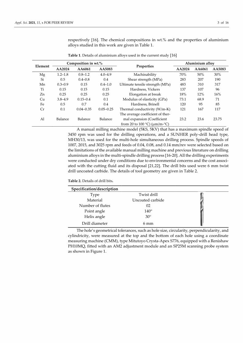
Table 2. Details of drill bits.
Specification/description
Type Twist drill
Material Uncoated carbide
Number of flutes 02
Point angle 140°
Helix angle 30°
Drill diameter 6 mm
The hole’s geometrical tolerances, such as hole size, circularity, perpendicularity, and
cylindricity, were measured at the top and the bottom of each hole using a coordinate
measuring machine (CMM), type Mitutoyo Crysta-Apex S776, equipped with a Renishaw
PH10MQ, fitted with an AM2 adjustment module and an SP25M scanning probe system
as shown in Figure 1.
Appl. Sci. 2021, 11, x FOR PEER REVIEW 4 of 16
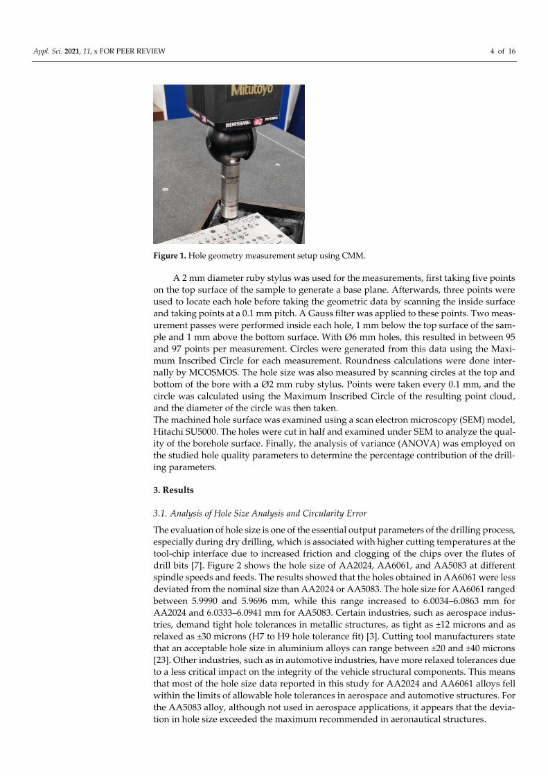
Figure 1. Hole geometry measurement setup using CMM.
A 2 mm diameter ruby stylus was used for the measurements, first taking five points
on the top surface of the sample to generate a base plane. Afterwards, three points were
used to locate each hole before taking the geometric data by scanning the inside surface
and taking points at a 0.1 mm pitch. A Gauss filter was applied to these points. Two meas-
urement passes were performed inside each hole, 1 mm below the top surface of the sam-
ple and 1 mm above the bottom surface. With Ø 6 mm holes, this resulted in between 95
and 97 points per measurement. Circles were generated from this data using the Maxi-
mum Inscribed Circle for each measurement. Roundness calculations were done inter-
nally by MCOSMOS. The hole size was also measured by scanning circles at the top and
bottom of the bore with a Ø 2 mm ruby stylus. Points were taken every 0.1 mm, and the
circle was calculated using the Maximum Inscribed Circle of the resulting point cloud,
and the diameter of the circle was then taken.
The machined hole surface was examined using a scan electron microscopy (SEM) model,
Hitachi SU5000. The holes were cut in half and examined under SEM to analyze the qual-
ity of the borehole surface. Finally, the analysis of variance (ANOVA) was employed on
the studied hole quality parameters to determine the percentage contribution of the drill-
ing parameters.
3. Results
3.1. Analysis of Hole Size Analysis and Circularity Error
The evaluation of hole size is one of the essential output parameters of the drilling process,
especially during dry drilling, which is associated with higher cutting temperatures at the
tool-chip interface due to increased friction and clogging of the chips over the flutes of
drill bits [7]. Figure 2 shows the hole size of AA2024, AA6061, and AA5083 at different
spindle speeds and feeds. The results showed that the holes obtained in AA6061 were less
deviated from the nominal size than AA2024 or AA5083. The hole size for AA6061 ranged
between 5.9990 and 5.9696 mm, while this range increased to 6.0034–6.0863 mm for
AA2024 and 6.0333–6.0941 mm for AA5083. Certain industries, such as aerospace indus-
tries, demand tight hole tolerances in metallic structures, as tight as ±12 microns and as
relaxed as ±30 microns (H7 to H9 hole tolerance fit) [3]. Cutting tool manufacturers state
that an acceptable hole size in aluminium alloys can range between ±20 and ±40 microns
[23]. Other industries, such as in automotive industries, have more relaxed tolerances due
to a less critical impact on the integrity of the vehicle structural components. This means
that most of the hole size data reported in this study for AA2024 and AA6061 alloys fell
within the limits of allowable hole tolerances in aerospace and automotive structures. For
the AA5083 alloy, although not used in aerospace applications, it appears that the devia-
tion in hole size exceeded the maximum recommended in aeronautical structures.

Appl. Sci. 2021, 11, x FOR PEER REVIEW 5 of 16
Figure 2. Effect of cutting parameters on hole size.
Similarly, hole size deviation in the AA6061 alloy reported in this study was significantly
lower than that reported in a recent study [24]. The only difference in the tools used in
both studies was that the previous study used coated tools (TiN, TiAlN, and TiN/TiAlN),
while the current study used uncoated tools. The coating layer thickness, despite being
less than several microns, might have had an impact on increasing the hole size deviation.
Therefore, it can be said that drilling an AA6061 alloy using uncoated carbide drills might
yield a hole size closer to the nominal drill diameter.
The results show that, in general, hole size tended to increase with the increase of the
spindle speed (n) and the feed (f), especially for the AA6061 and AA5083 alloys. This could
be attributed to the increased vibratory displacement with the increase of the n and the f,
which occurs during the initial contact between the chisel edge and the workpiece and
triggers dynamic instability, causing higher hole size deviations [7,25]. However, it is ev-
ident from Table 3 that the impact of f on the hole deviation was found to be insignificant,
with a percentage contribution of 2.74%. Overall, the hole deviation was affected more by
the type of alloy, with a percentage contribution of 51.75%. The influence of n was found
to be 9.71%, while the two-way interaction of spindle speed and alloy type significantly
impacted hole size with a contribution of 24.81%.
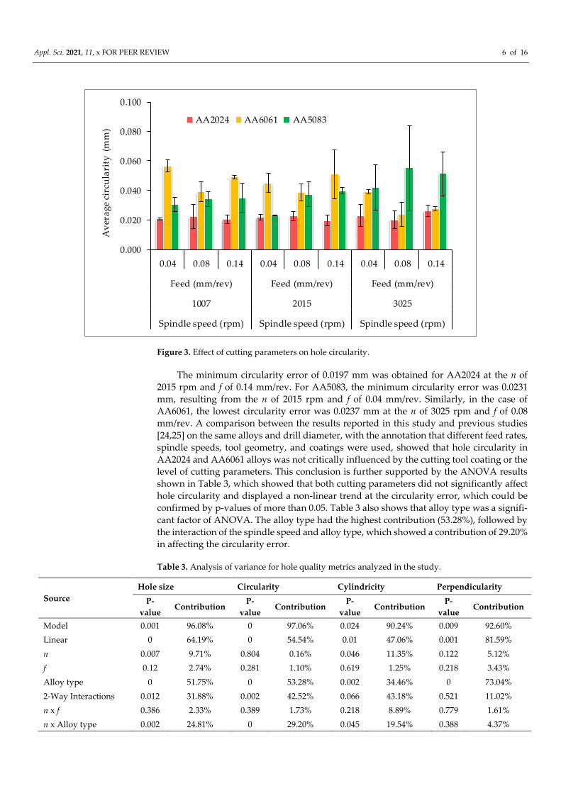
Figure 3 shows the circularity error of the hole at different drilling parameters during
multi-hole simultaneous drilling for all the three alloys selected in this study. It is illus-
trated in Figure 3 that drilling in AA2024 showed less hole circularity error than AA5083
and AA6061 alloys, irrespective of the drilling parameters. AA5083 showed a higher cir-
cularity error than that obtained in the drilling of AA6061; however, at the n of 3025 rpm,
the circularity error increased compared to AA6061. This means that AA5083 performs
better when machined at the lower n, while the AA6061 alloy shows lower hole circularity
error when machined at a higher n. This could mainly be attributed to the higher magne-
sium content in the AA5083 alloy compared to the AA6061 alloy. Furthermore, adding
magnesium to aluminium alloys contributes to maintaining a high degree of ductil-
ity/formability but is also known to be thermodynamically unstable at higher tempera-
tures. This, in return, means that lower cutting parameters are more suited for softer alu-
minium alloys like AA5083 [26].
Appl. Sci. 2021, 11, x FOR PEER REVIEW 6 of 16
0.000
0.020
0.040
0.060
0.080
0.100
0.04 0.08 0.14 0.04 0.08 0.14 0.04 0.08 0.14
Feed (mm/rev) Feed (mm/rev) Feed (mm/rev)
1007 2015 3025
Spindle speed (rpm) Spindle speed (rpm) Spindle speed (rpm)
Av
era
ge
circ
ula
rity
(m
m)
AA2024 AA6061 AA5083
Figure 3. Effect of cutting parameters on hole circularity.
The minimum circularity error of 0.0197 mm was obtained for AA2024 at the n of
2015 rpm and f of 0.14 mm/rev. For AA5083, the minimum circularity error was 0.0231
mm, resulting from the n of 2015 rpm and f of 0.04 mm/rev. Similarly, in the case of
AA6061, the lowest circularity error was 0.0237 mm at the n of 3025 rpm and f of 0.08
mm/rev. A comparison between the results reported in this study and previous studies
[24,25] on the same alloys and drill diameter, with the annotation that different feed rates,
spindle speeds, tool geometry, and coatings were used, showed that hole circularity in
AA2024 and AA6061 alloys was not critically influenced by the cutting tool coating or the
level of cutting parameters. This conclusion is further supported by the ANOVA results
shown in Table 3, which showed that both cutting parameters did not significantly affect
hole circularity and displayed a non-linear trend at the circularity error, which could be
confirmed by p-values of more than 0.05. Table 3 also shows that alloy type was a signifi-
cant factor of ANOVA. The alloy type had the highest contribution (53.28%), followed by
the interaction of the spindle speed and alloy type, which showed a contribution of 29.20%
in affecting the circularity error.
Table 3. Analysis of variance for hole quality metrics analyzed in the study.
Source
Hole size Circularity Cylindricity Perpendicularity
P-
value Contribution
P-
value Contribution
P-
value Contribution
P-
value Contribution
Model 0.001 96.08% 0 97.06% 0.024 90.24% 0.009 92.60%
Linear 0 64.19% 0 54.54% 0.01 47.06% 0.001 81.59%
n 0.007 9.71% 0.804 0.16% 0.046 11.35% 0.122 5.12%
f 0.12 2.74% 0.281 1.10% 0.619 1.25% 0.218 3.43%
Alloy type 0 51.75% 0 53.28% 0.002 34.46% 0 73.04%
2-Way Interactions 0.012 31.88% 0.002 42.52% 0.066 43.18% 0.521 11.02%
n x f 0.386 2.33% 0.389 1.73% 0.218 8.89% 0.779 1.61%
n x Alloy type 0.002 24.81% 0 29.20% 0.045 19.54% 0.388 4.37%

Appl. Sci. 2021, 11, x FOR PEER REVIEW 7 of 16
f x Alloy type 0.134 4.74% 0.007 11.59% 0.086 14.75% 0.328 5.04%
Error - 3.92% - 2.94% - 9.76% - 7.40%
Total - 100.00% - 100.00% - 100.00% - 100.00%
3.2. Hole Cylindricity and Perpendicularity
Figure 4 shows the average values of hole cylindricity for AA2024, AA6061, and AA5083.
The results showed that the lowest hole cylindricity error was possible when drilling
AA2024, followed by AA6061 and then AA5083. The result showed that the lowest cylin-
dricity error of 0.0240 mm was obtained during the drilling of AA2024, which was possi-
ble at the n of 1007 rpm and f of 0.04 mm/rev. For AA6061, the minimum cylindricity error
was 0.0389 mm and resulted at the n of 3025 rpm and f of 0.08 mm/rev. The minimum hole
cylindricity of 0.0403 mm for AA5083 was possible at the n of 1007 rpm and the f of 0.04
mm/rev. These results agreed with the results obtained in the circularity error, where
AA6061 showed the highest cylindricity error at low n. At the same time, AA5083 had the
maximum cylindricity error at the highest n of 3025 rpm, while a higher n resulted in less
circularity error for AA6061. Table 3 shows that the n was somewhat influential on the
cylindricity error with a percentage contribution of 11.35%; however, the impact of feed
and other interactions was insignificant. The most dominant factor in regard to cylin-
dricity was the alloy type, with a percentage contribution of 34.46%.
0.000
0.020
0.040
0.060
0.080
0.100
0.04 0.08 0.14 0.04 0.08 0.14 0.04 0.08 0.14
Feed (mm/rev) Feed (mm/rev) Feed (mm/rev)
1007 2015 3025
Spindle speed (rpm) Spindle speed (rpm) Spindle speed (rpm)
Av
era
ge
circ
ula
rity
(m
m)
AA2024 AA6061 AA5083
Figure 4. Effect of cutting parameters on hole cylindricity.
Similarly, the perpendicularity error for alloys selected in this study during multi-
spindle simultaneous drilling is illustrated in Figure 5. Interestingly, the holes produced
in AA2024 also gave the lowest perpendicularity, ranging between 0.0080 and 0.0178 mm.
AA5083 followed with minimum and maximum perpendicularity errors of 0.0222 and
0.0694, respectively. In contrast, AA6061 showed the maximum perpendicularity error,
which ranged between 0.0331 and 0.0579. The minimum value of the perpendicularity
error for AA2024 was obtained at the n of 3025 rpm and f of 0.08 mm/rev. In contrast, the
same f of 0.04 mm/rev and spindle speeds of 1007 rpm and 2017 rpm caused the minimum
perpendicularity for AA5083 and AA6061, respectively. However, like the cylindricity er-
ror, it was also evident from the ANOVA result that the only parameter that had the

Appl. Sci. 2021, 11, x FOR PEER REVIEW 8 of 16
highest influence on the perpendicularity error was the alloy type, with a percentage con-
tribution of 73.04%, while none of the other parameters showed a significant impact on
the perpendicularity error.
0.0000
0.0300
0.0600
0.0900
0.1200
0.04 0.08 0.14 0.04 0.08 0.14 0.04 0.08 0.14
Feed (mm/rev) Feed (mm/rev) Feed (mm/rev)
1007 2015 3025
Spindle speed (rpm) Spindle speed (rpm) Spindle speed (rpm)
Per
pen
dic
ula
rity
(mm
)
AA2024 AA6061 AA5083
Figure 5. Effect of cutting parameters on hole perpendicularity.
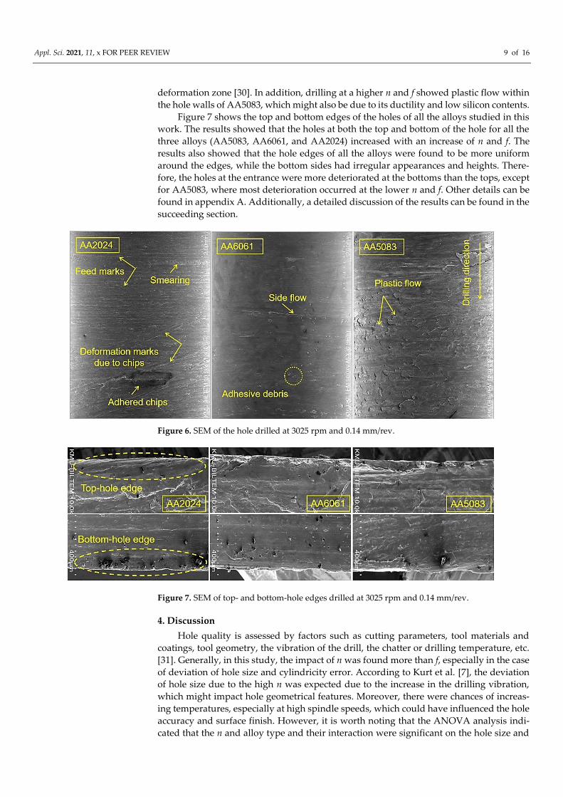
3.3. Surface Damage Analysis
Figure 6 shows SEM images of the inner borehole wall conditions of AA2024,
AA6061, and AA5083 for holes drilled under dry conditions during the multi-spindle sim-
ultaneous drilling process. It was observed from the SEM micrographs that the damage
and distortion found in the holes increased with the increase in spindle speed (n) and the
feed (f). This is speculated to be due to the increase in vibration level, which influenced
the geometrical hole tolerances. Additionally, it can be attributed to the increased thermal
softening of the work material because of the rise in cutting temperatures with the increase
of n and deformations due to an increase in the f [27].
Figure 6 also revealed the formation of feed marks, deformation marks due to chips
evacuation, adhesive debris, smearing, and plastic flow on the surface of aluminium al-
loys. Smearing is a thin layer of plastic deformation that forms at the surface of the work-
piece. It is often difficult to recognize and mainly occurs in materials with ductile natures
[28]. The smearing in this instance appeared due to the rise in temperature because of
increased n and f. The random chip debris on some of the surfaces of the hole walls was
also caused by the generation of material smearing [27]. Moreover, the deformation marks
might be either due to the rubbing action of the chips that collided with the hole walls
during evacuation [3]. The feed marks occurred as a result of an increase in feed. Further-
more, there were also chances of material side flow near the regions of feed marks where
the plastically deformed material was ploughed aside due to the high thrust force and
cutting temperature when the tool was used under dry cutting conditions [29]. Interest-
ingly, no visible cracks were found on the surface under all cutting conditions. However,
the damage and distortion in the hole of AA5083 were found more often than those seen
in AA2024 and AA6061. A likely explanation for this might be the poor thermal conduc-
tivity of the work material, which enhances the heat accumulation in the primary
Appl. Sci. 2021, 11, x FOR PEER REVIEW 9 of 16
deformation zone [30]. In addition, drilling at a higher n and f showed plastic flow within
the hole walls of AA5083, which might also be due to its ductility and low silicon contents.
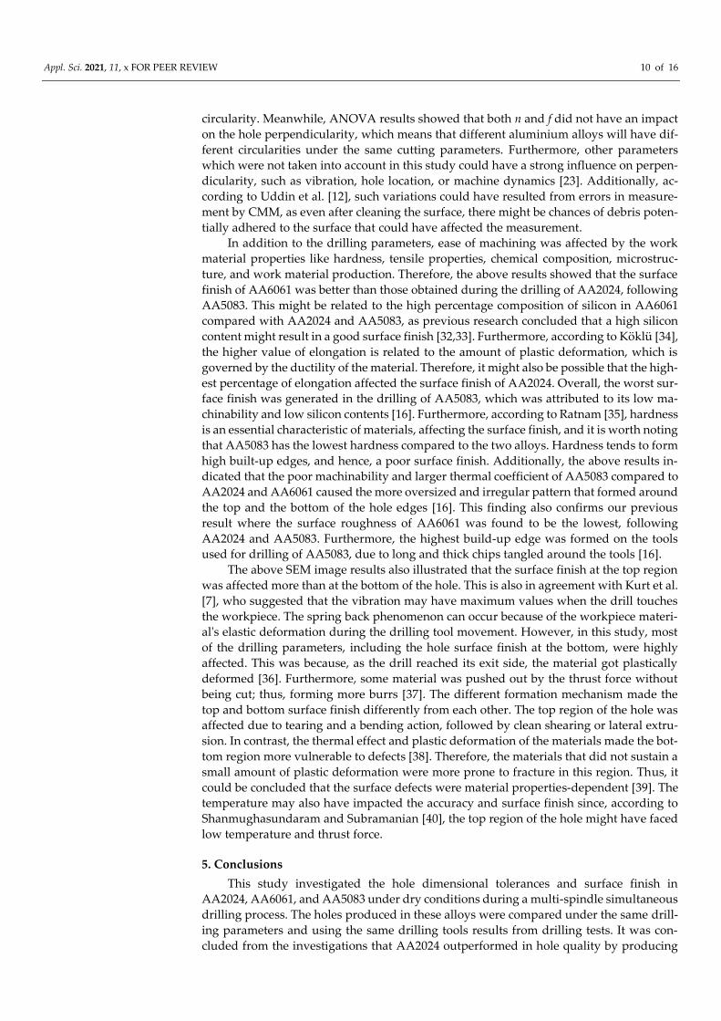
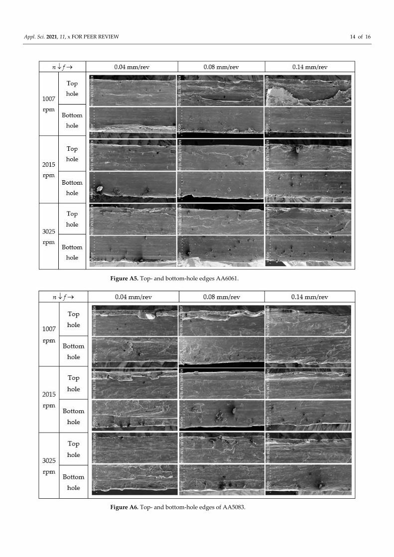
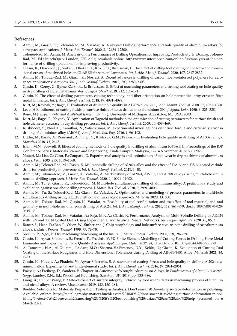
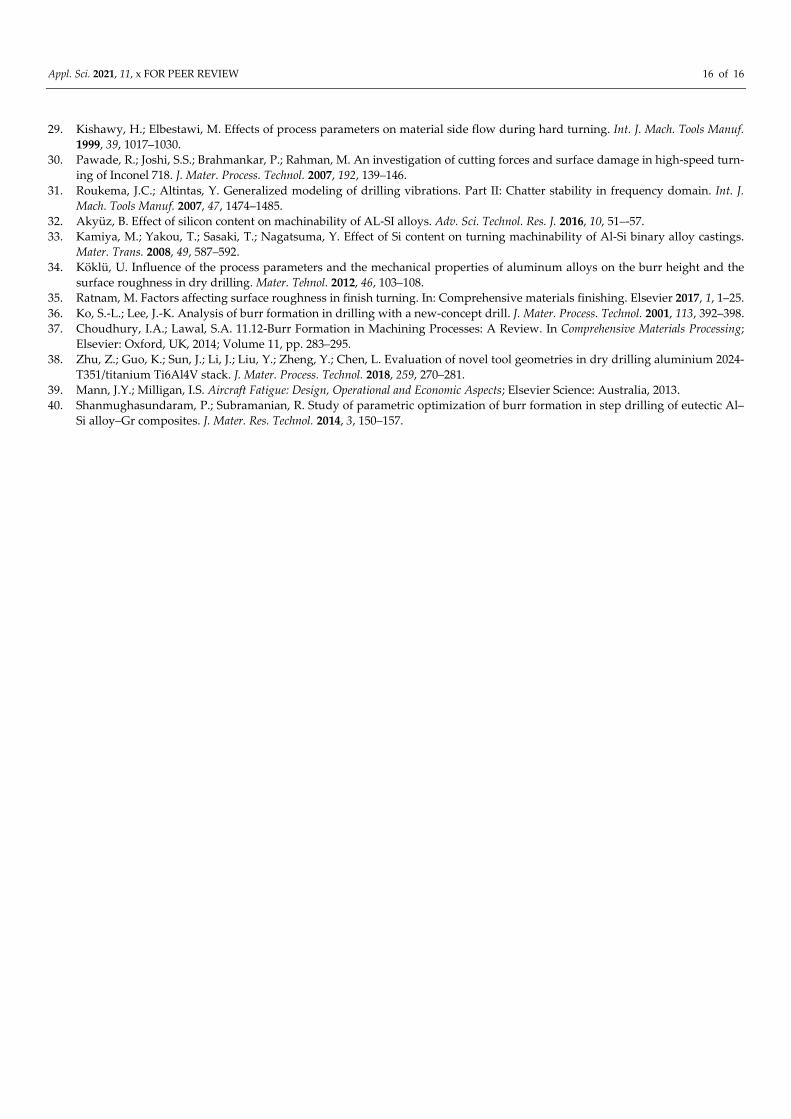
Figure 7 shows the top and bottom edges of the holes of all the alloys studied in this
work. The results showed that the holes at both the top and bottom of the hole for all the
three alloys (AA5083, AA6061, and AA2024) increased with an increase of n and f. The
results also showed that the hole edges of all the alloys were found to be more uniform
around the edges, while the bottom sides had irregular appearances and heights. There-
fore, the holes at the entrance were more deteriorated at the bottoms than the tops, except
for AA5083, where most deterioration occurred at the lower n and f. Other details can be
found in appendix A. Additionally, a detailed discussion of the results can be found in the
succeeding section.
Figure 6. SEM of the hole drilled at 3025 rpm and 0.14 mm/rev.
Figure 7. SEM of top- and bottom-hole edges drilled at 3025 rpm and 0.14 mm/rev.
4. Discussion
Hole quality is assessed by factors such as cutting parameters, tool materials and
coatings, tool geometry, the vibration of the drill, the chatter or drilling temperature, etc.
[31]. Generally, in this study, the impact of n was found more than f, especially in the case
of deviation of hole size and cylindricity error. According to Kurt et al. [7], the deviation
of hole size due to the high n was expected due to the increase in the drilling vibration,
which might impact hole geometrical features. Moreover, there were chances of increas-
ing temperatures, especially at high spindle speeds, which could have influenced the hole
accuracy and surface finish. However, it is worth noting that the ANOVA analysis indi-
cated that the n and alloy type and their interaction were significant on the hole size and
Appl. Sci. 2021, 11, x FOR PEER REVIEW 10 of 16
circularity. Meanwhile, ANOVA results showed that both n and f did not have an impact
on the hole perpendicularity, which means that different aluminium alloys will have dif-
ferent circularities under the same cutting parameters. Furthermore, other parameters
which were not taken into account in this study could have a strong influence on perpen-
dicularity, such as vibration, hole location, or machine dynamics [23]. Additionally, ac-
cording to Uddin et al. [12], such variations could have resulted from errors in measure-
ment by CMM, as even after cleaning the surface, there might be chances of debris poten-
tially adhered to the surface that could have affected the measurement.
In addition to the drilling parameters, ease of machining was affected by the work
material properties like hardness, tensile properties, chemical composition, microstruc-
ture, and work material production. Therefore, the above results showed that the surface
finish of AA6061 was better than those obtained during the drilling of AA2024, following
AA5083. This might be related to the high percentage composition of silicon in AA6061
compared with AA2024 and AA5083, as previous research concluded that a high silicon
content might result in a good surface finish [32,33]. Furthermore, according to Köklü [34],
the higher value of elongation is related to the amount of plastic deformation, which is
governed by the ductility of the material. Therefore, it might also be possible that the high-
est percentage of elongation affected the surface finish of AA2024. Overall, the worst sur-
face finish was generated in the drilling of AA5083, which was attributed to its low ma-
chinability and low silicon contents [16]. Furthermore, according to Ratnam [35], hardness
is an essential characteristic of materials, affecting the surface finish, and it is worth noting
that AA5083 has the lowest hardness compared to the two alloys. Hardness tends to form
high built-up edges, and hence, a poor surface finish. Additionally, the above results in-
dicated that the poor machinability and larger thermal coefficient of AA5083 compared to
AA2024 and AA6061 caused the more oversized and irregular pattern that formed around
the top and the bottom of the hole edges [16]. This finding also confirms our previous
result where the surface roughness of AA6061 was found to be the lowest, following
AA2024 and AA5083. Furthermore, the highest build-up edge was formed on the tools
used for drilling of AA5083, due to long and thick chips tangled around the tools [16].
The above SEM image results also illustrated that the surface finish at the top region
was affected more than at the bottom of the hole. This is also in agreement with Kurt et al.
[7], who suggested that the vibration may have maximum values when the drill touches
the workpiece. The spring back phenomenon can occur because of the workpiece materi-
al's elastic deformation during the drilling tool movement. However, in this study, most
of the drilling parameters, including the hole surface finish at the bottom, were highly
affected. This was because, as the drill reached its exit side, the material got plastically
deformed [36]. Furthermore, some material was pushed out by the thrust force without
being cut; thus, forming more burrs [37]. The different formation mechanism made the
top and bottom surface finish differently from each other. The top region of the hole was
affected due to tearing and a bending action, followed by clean shearing or lateral extru-
sion. In contrast, the thermal effect and plastic deformation of the materials made the bot-
tom region more vulnerable to defects [38]. Therefore, the materials that did not sustain a
small amount of plastic deformation were more prone to fracture in this region. Thus, it
could be concluded that the surface defects were material properties-dependent [39]. The
temperature may also have impacted the accuracy and surface finish since, according to
Shanmughasundaram and Subramanian [40], the top region of the hole might have faced
low temperature and thrust force.
5. Conclusions
This study investigated the hole dimensional tolerances and surface finish in
AA2024, AA6061, and AA5083 under dry conditions during a multi-spindle simultaneous
drilling process. The holes produced in these alloys were compared under the same drill-
ing parameters and using the same drilling tools results from drilling tests. It was con-
cluded from the investigations that AA2024 outperformed in hole quality by producing

Appl. Sci. 2021, 11, x FOR PEER REVIEW 11 of 16
less circularity error, cylindricity error, and perpendicularity error, irrespective of the
drilling parameters. Only in the case of hole size, the holes drilled in AA6061 were less
deviated from the nominal size. This was followed by AA2024 and then AA5083. SEM
examination revealed surface damage in the form of metal debris adhesion, smeared ma-
terial, side flow, and feed marks. The worst surface finish and the most oversized and
irregular patterns formed around the top and bottom of the hole edges generated in the
drilling of AA5083 due to its low machinability, low hardness value, low silicon contents,
and large coefficient of thermal expansion. The spindle speed was found to be more influ-
ential than feed and affected the hole size with a percentage contribution of 9.71% for hole
size and 11.35% cylindricity error. The spindle speed and feed showed an insignificant
effect on the circularity error and perpendicularity error; however, in general, a non-linear
trend was observed in affecting the hole quality. These variations were expected due to
the minute cutting debris potentially adhered to the surface that affected the CMM meas-
urement. Furthermore, the machine drill vibration and temperature variations were not
considered in this study and need further investigation during the multi-spindle drilling
process.
Author Contributions: Conceptualization, M.A., and M.T-R.; methodology, M.A., M.T-R., and K.G.;
validation, M.A., M.T-R., K.G., A.V., U.K., and W.K; investigation, M.A., K.G., U.K., and W.K.; writ-
ing—original draft preparation, M.A.; writing—review and editing, M.T-R., K.G., U.K., and A.V.
All authors have read and agreed to the published version of the manuscript.
Funding: This research received no external funding.
Institutional Review Board Statement: Not applicable.
Informed Consent Statement: Not applicable.
Data Availability Statement: The data presented in this study are available on request.
Acknowledgments: The first author would like to thank Edith Cowan University for the awarded
(ECU-HDR) higher degree research scholarship.
Conflicts of Interest: The authors declare no conflicts of interest.
Appendix A:
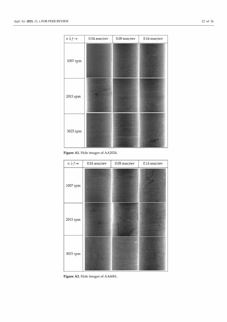
Appl. Sci. 2021, 11, x FOR PEER REVIEW 12 of 16
Figure A1. Hole images of AA2024.
Figure A2. Hole images of AA6061.
Appl. Sci. 2021, 11, x FOR PEER REVIEW 13 of 16
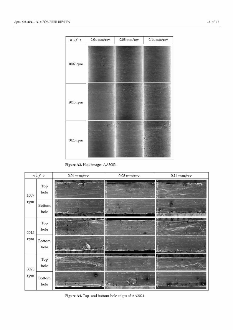
Figure A3. Hole images AA5083.
Figure A4. Top- and bottom-hole edges of AA2024.
Appl. Sci. 2021, 11, x FOR PEER REVIEW 14 of 16
Figure A5. Top- and bottom-hole edges AA6061.
Figure A6. Top- and bottom-hole edges of AA5083.
Appl. Sci. 2021, 11, x FOR PEER REVIEW 15 of 16
References
1. Aamir, M.; Giasin, K.; Tolouei-Rad, M.; Vafadar, A. A review: Drilling performance and hole quality of aluminium alloys for
aerospace applications. J. Mater. Res. Technol. 2020, 9, 12484–12500.
2. Tolouei-Rad, M.; Aamir, M. Analysis of the Performance of Drilling Operations for Improving Productivity. In Drilling; Tolouei-
Rad, M., Ed.; IntechOpen: London, UK, 2021; Available online: https://www.intechopen.com/online-first/analysis-of-the-per-
formance-of-drilling-operations-for-improving-productivity.
3. Giasin, K.; Hawxwell, J.; Sinke, J.; Dhakal, H.; Köklü, U.; Brousseau, E. The effect of cutting tool coating on the form and dimen-
sional errors of machined holes in GLARE® fibre metal laminates. Int. J. Adv. Manuf. Technol. 2020, 107, 2817-2832.
4. Aamir, M.; Tolouei-Rad, M.; Giasin, K.; Nosrati, A. Recent advances in drilling of carbon fiber–reinforced polymers for aero-
space applications: A review. Int. J. Adv. Manuf. Technol. 2019, 105, 2289–2308.
5. Giasin, K.; Gorey, G.; Byrne, C.; Sinke, J.; Brousseau, E. Effect of machining parameters and cutting tool coating on hole quality
in dry drilling of fibre metal laminates. Compos. Struct. 2019, 212, 159–174.
6. Giasin, K. The effect of drilling parameters, cooling technology, and fiber orientation on hole perpendicularity error in fiber
metal laminates. Int. J. Adv. Manuf. Technol. 2018, 97, 4081–4099.
7. Kurt, M.; Kaynak, Y.; Bagci, E. Evaluation of drilled hole quality in Al 2024 alloy. Int. J. Adv. Manuf. Technol. 2008, 37, 1051–1060.
8. Leep, H.R. Influence of cutting fluids on surface finish of holes drilled into aluminium 390. J. Synth. Lubr. 1990, 6, 325–338.
9. Bono, M.J. Experimental and Analytical Issues in Drilling; University of Michigan: Ann Arbor, MI, USA, 2003.
10. Kurt, M.; Bagci, E.; Kaynak, Y. Application of Taguchi methods in the optimization of cutting parameters for surface finish and
hole diameter accuracy in dry drilling processes. Int. J. Adv. Manuf. Technol. 2009, 40, 458–469.
11. Kushnoore, S.; Noel, D.; Kamitkar, N.; Satishkumar, M. Experimental investigations on thrust, torque and circularity error in
drilling of aluminium alloy (Al6061). Am. J. Mech. Ind. Eng. 2016, 1, 96–102.
12. Uddin, M.; Basak, A.; Pramanik, A.; Singh, S.; Krolczyk, G.M.; Prakash, C. Evaluating hole quality in drilling of Al 6061 alloys.
Materials 2018, 11, 2443.
13. Islam, M.N.; Boswell, B. Effect of cooling methods on hole quality in drilling of aluminium 6061-6T. In Proceedings of the IOP
Conference Series: Materials Science and Engineering, Kuala Lumpur, Malaysia, 12–14 November 2015; p. 012022.
14. Nouari, M.; List, G.; Girot, F.; Coupard, D. Experimental analysis and optimisation of tool wear in dry machining of aluminium
alloys. Wear 2003, 255, 1359–1368.
15. Aamir, M.; Tolouei-Rad, M.; Giasin, K. Multi-spindle drilling of Al2024 alloy and the effect of TiAlN and TiSiN-coated carbide
drills for productivity improvement. Int. J. Adv. Manuf. Technol. 2021, 1–10.
16. Aamir, M.; Tolouei-Rad, M.; Giasin, K.; Vafadar, A. Machinability of Al2024, Al6061, and Al5083 alloys using multi-hole simul-
taneous drilling approach. J. Mater. Res. Technol. 2020, 9, 10991–11002.
17. Aamir, M.; Tu, S.; Giasin, K.; Tolouei-Rad, M. Multi-hole simultaneous drilling of aluminium alloy: A preliminary study and
evaluation against one-shot drilling process. J. Mater. Res. Technol. 2020, 9, 3994–4006.
18. Aamir, M.; Tu, S.; Tolouei-Rad, M.; Giasin, K.; Vafadar, A. Optimization and modeling of process parameters in multi-hole
simultaneous drilling using taguchi method and fuzzy logic approach. Materials 2020, 13, 680.
19. Aamir, M.; Tolouei-Rad, M.; Giasin, K.; Vafadar, A. Feasibility of tool configuration and the effect of tool material, and tool
geometry in multi-hole simultaneous drilling of Al2024. Int. J. Adv. Manuf. Technol. 2020, 111, 861–879, doi:10.1007/s00170-020-
06151-7.
20. Aamir, M.; Tolouei-Rad, M.; Vafadar, A.; Raja, M.N.A.; Giasin, K. Performance Analysis of Multi-Spindle Drilling of Al2024
with TiN and TiCN Coated Drills Using Experimental and Artificial Neural Networks Technique. Appl. Sci. 2020, 10, 8633.
21. Batzer, S.; Haan, D.; Rao, P.; Olson, W.; Sutherland, J. Chip morphology and hole surface texture in the drilling of cast aluminum
alloys. J. Mater. Process. Technol. 1998, 79, 72–78.
22. Sreejith, P.; Ngoi, B. Dry machining: Machining of the future. J. Mater. Process. Technol. 2000, 101, 287–291.
23. Giasin, K.; Ayvar-Soberanis, S.; French, T.; Phadnis, V. 3D Finite Element Modelling of Cutting Forces in Drilling Fibre Metal
Laminates and Experimental Hole Quality Analysis. Appl. Compos. Mater. 2017, 24, 113–137, doi:10.1007/s10443-016-9517-0.
24. Al-Tameemi, H.A.; Al-Dulaimi, T.; Awe, M.O.; Sharma, S.; Pimenov, D.Y.; Koklu, U.; Giasin, K. Evaluation of Cutting-Tool
Coating on the Surface Roughness and Hole Dimensional Tolerances during Drilling of Al6061-T651 Alloy. Materials 2021, 14,
1783.
25. Giasin, K.; Hodzic, A.; Phadnis, V.; Ayvar-Soberanis, S. Assessment of cutting forces and hole quality in drilling Al2024 alu-
minium alloy: Experimental and finite element study. Int. J. Adv. Manuf. Technol. 2016, 87, 2041–2061.
26. Poznak, A.; Freiberg, D.; Sanders, P. Chapter 10-Automotive Wrought Aluminium Alloys. In Fundamentals of Aluminium Metal-
lurgy, Lumley, R.N., Ed.; Woodhead Publishing: Sawston, UK, 2018; pp. 333–386.
27. Liang, X.; Liu, Z.; Wang, B. State-of-the-art of surface integrity induced by tool wear effects in machining process of titanium
and nickel alloys: A review. Measurement 2019, 132, 150–181.
28. Buehler. Solutions for Materials Preparation, Testing & Analysis: Don’t smear it! Avoiding surface deformation in polishing.
Available online: https://metallography-matters.buehler.com/2018/09/17/dont-smear-it-avoiding-surface-deformation-in-pol-
ishing/#:~:text=To%20prevent%20smearing%2C%20it's%20best,polishing%20surface%20can%20also%20help (accessed on 6
March 2021).
Appl. Sci. 2021, 11, x FOR PEER REVIEW 16 of 16
29. Kishawy, H.; Elbestawi, M. Effects of process parameters on material side flow during hard turning. Int. J. Mach. Tools Manuf.
1999, 39, 1017–1030.
30. Pawade, R.; Joshi, S.S.; Brahmankar, P.; Rahman, M. An investigation of cutting forces and surface damage in high-speed turn-
ing of Inconel 718. J. Mater. Process. Technol. 2007, 192, 139–146.
31. Roukema, J.C.; Altintas, Y. Generalized modeling of drilling vibrations. Part II: Chatter stability in frequency domain. Int. J.
Mach. Tools Manuf. 2007, 47, 1474–1485.
32. Akyüz, B. Effect of silicon content on machinability of AL-SI alloys. Adv. Sci. Technol. Res. J. 2016, 10, 51–-57.
33. Kamiya, M.; Yakou, T.; Sasaki, T.; Nagatsuma, Y. Effect of Si content on turning machinability of Al-Si binary alloy castings.
Mater. Trans. 2008, 49, 587–592.
34. Köklü, U. Influence of the process parameters and the mechanical properties of aluminum alloys on the burr height and the
surface roughness in dry drilling. Mater. Tehnol. 2012, 46, 103–108.
35. Ratnam, M. Factors affecting surface roughness in finish turning. In: Comprehensive materials finishing. Elsevier 2017, 1, 1–25.
36. Ko, S.-L.; Lee, J.-K. Analysis of burr formation in drilling with a new-concept drill. J. Mater. Process. Technol. 2001, 113, 392–398.
37. Choudhury, I.A.; Lawal, S.A. 11.12-Burr Formation in Machining Processes: A Review. In Comprehensive Materials Processing;
Elsevier: Oxford, UK, 2014; Volume 11, pp. 283–295.
38. Zhu, Z.; Guo, K.; Sun, J.; Li, J.; Liu, Y.; Zheng, Y.; Chen, L. Evaluation of novel tool geometries in dry drilling aluminium 2024-
T351/titanium Ti6Al4V stack. J. Mater. Process. Technol. 2018, 259, 270–281.
39. Mann, J.Y.; Milligan, I.S. Aircraft Fatigue: Design, Operational and Economic Aspects; Elsevier Science: Australia, 2013.
40. Shanmughasundaram, P.; Subramanian, R. Study of parametric optimization of burr formation in step drilling of eutectic Al–
Si alloy–Gr composites. J. Mater. Res. Technol. 2014, 3, 150–157.
Related Documents