C.K. Clarke Metallurgical Consulting Inc. Mobile, Alabama metallurgical analysis to de- termine whether a #12 solid, THHN copper wire had been energized and thus could have been the cause of a major fire loss is presented in this article. The wire was used to run temporary lighting in the attic space of a large single-story wooden commercial building under construction. Tempo- rary wiring for light had been strung over wooden ceiling joists and sta- pled in place. One theory for the cause of the fire was that the current in the wire in- duced a current in a staple driven too hard into a wood joist. Adding insu- lation over this area could trap heat generated in the staple and ignite a fire. The fire started within a few hours of installation of insulation in the attic. A point of origin of the fire was lo- cated in the ceiling of one room in the building. Several pieces of wire were found on the floor of the room after the ceiling collapsed, and fire inves- tigators recovered two wire ends that appeared to show evidence for a parting arc. The parting arc issue was important because the temporary lighting wire represented a possible fire origin, and it was not supposed to be present, much less energized, at the time of the blaze. The NFPA 921 Guide for Fire and Ex- plosion Investigations 2004, provides photographic examples of wires with parting arcs, but it includes no met- allurgical investigation. A parting arc in this case would have occurred after the fire had started, as the hot, ener- gized wire was pulled apart. The arc was not considered to be the cause of the fire because of its short duration, but it was evidence for flowing cur- rent. The purpose of the following work was to determine if the peculiar nature of the separation showed evi- dence for a flow of current or only a parting arc. Examination procedure Only one of two separate parting arc ends was permitted to be destruc- tively examined. However, other wire samples were allowed to be removed from the collected wire pieces for met- allographic evaluation. Three different new wire samples were purchased to provide a reason- able idea of the as-produced wire structure. (No samples of the original wire without fire damage were available.) The wire end in question was pho- tographed with both conventional photography and with a scanning A metallurgical analysis to determine the cause of a fire TECH SPOTLIGHT Evaluation of fire damaged copper wire Fig. 1 and 2 (inset) — These show two views of the wire end as it was received. All of the wire insulation had been burned away, as it was on most of the wire recovered. Material appears to have been blown away at the end of the wire. A ADVANCED MATERIALS & PROCESSES/APRIL 2006 01

Welcome message from author
This document is posted to help you gain knowledge. Please leave a comment to let me know what you think about it! Share it to your friends and learn new things together.
Transcript
C.K. ClarkeMetallurgical Consulting Inc.Mobile, Alabama
metallurgical analysis to de-termine whether a #12solid, THHN copper wirehad been energized andthus could have been thecause of a major fire loss ispresented in this article. The
wire was used to run temporarylighting in the attic space of a largesingle-story wooden commercialbuilding under construction. Tempo-rary wiring for light had been strungover wooden ceiling joists and sta-pled in place.
One theory for the cause of the firewas that the current in the wire in-duced a current in a staple driven toohard into a wood joist. Adding insu-lation over this area could trap heat
generated in the staple and ignite afire. The fire started within a fewhours of installation of insulation inthe attic.
A point of origin of the fire was lo-cated in the ceiling of one room in thebuilding. Several pieces of wire werefound on the floor of the room afterthe ceiling collapsed, and fire inves-tigators recovered two wire ends thatappeared to show evidence for aparting arc. The parting arc issue wasimportant because the temporarylighting wire represented a possiblefire origin, and it was not supposedto be present, much less energized, atthe time of the blaze.
The NFPA921 Guide for Fire and Ex-plosion Investigations 2004, providesphotographic examples of wires withparting arcs, but it includes no met-allurgical investigation. Aparting arcin this case would have occurred afterthe fire had started, as the hot, ener-gized wire was pulled apart. The arc
was not considered to be the cause ofthe fire because of its short duration,but it was evidence for flowing cur-rent. The purpose of the followingwork was to determine if the peculiarnature of the separation showed evi-dence for a flow of current or only aparting arc.
Examination procedureOnly one of two separate parting
arc ends was permitted to be destruc-tively examined. However, other wiresamples were allowed to be removedfrom the collected wire pieces for met-allographic evaluation.
Three different new wire sampleswere purchased to provide a reason-able idea of the as-produced wirestructure. (No samples of the originalwire without fire damage wereavailable.)
The wire end in question was pho-tographed with both conventionalphotography and with a scanning
A metallurgical analysis to determine the cause of a fire
TECH SPOTLIGHT
Evaluation of fire damaged copper wire
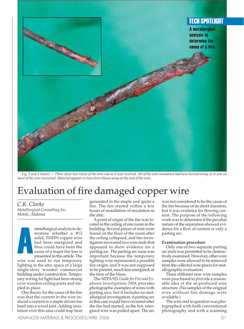
Fig. 1 and 2 (inset) — These show two views of the wire end as it was received. All of the wire insulation had been burned away, as it was onmost of the wire recovered. Material appears to have been blown away at the end of the wire.
A
ADVANCED MATERIALS & PROCESSES/APRIL 2006 01
electron microscope (SEM) prior tomounting the wire for a longitudinalsection for metallography. Two dif-ferent etchants were applied to revealthe grain structure:
• 1:1:1 H2O2:NH4OH:H2O and • K2Cr2O2, H2SO4, NaCl saturated
solution Both enchants yielded the same
good delineation of grain size. The hy-drogen peroxide etch revealed goodgrain boundary detail at high magni-fication, while the potassium dichro-mate showed good grain contrast.
Wire characteristicsFigures 1 and 2 show two views of
the wire end as it was received. All ofthe wire insulation had been burnedaway, as it was on most of the wire re-covered. Material appears to havebeen blown away at the end of thewire. (This is typical of arc damagefrom other cases. For example, Fig. 3shows the broken end of a bare power
line that failed while carrying current,although no fire was involved.)
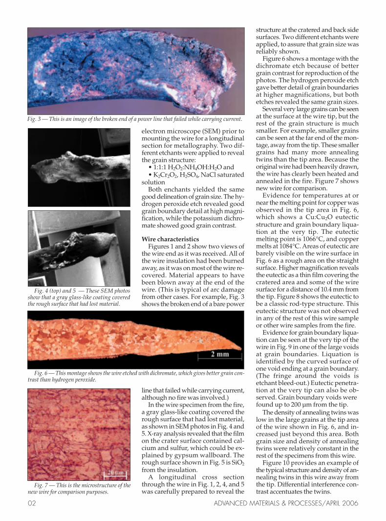
In the wire specimen from the fire,a gray glass-like coating covered therough surface that had lost material,as shown in SEM photos in Fig. 4 and5. X-ray analysis revealed that the filmon the crater surface contained cal-cium and sulfur, which could be ex-plained by gypsum wallboard. Therough surface shown in Fig. 5 is SiO2
from the insulation.A longitudinal cross section
through the wire in Fig. 1, 2, 4, and 5was carefully prepared to reveal the
structure at the cratered and back sidesurfaces. Two different etchants wereapplied, to assure that grain size wasreliably shown.
Figure 6 shows a montage with thedichromate etch because of bettergrain contrast for reproduction of thephotos. The hydrogen peroxide etchgave better detail of grain boundariesat higher magnifications, but bothetches revealed the same grain sizes.
Several very large grains can be seenat the surface at the wire tip, but therest of the grain structure is muchsmaller. For example, smaller grainscan be seen at the far end of the mon-tage, away from the tip. These smallergrains had many more annealingtwins than the tip area. Because theoriginal wire had been heavily drawn,the wire has clearly been heated andannealed in the fire. Figure 7 showsnew wire for comparison.
Evidence for temperatures at ornear the melting point for copper wasobserved in the tip area in Fig. 6,which shows a Cu:Cu2O eutecticstructure and grain boundary liqua-tion at the very tip. The eutecticmelting point is 1066°C, and coppermelts at 1084°C. Areas of eutectic arebarely visible on the wire surface inFig. 6 as a rough area on the straightsurface. Higher magnification revealsthe eutectic as a thin film covering thecratered area and some of the wiresurface for a distance of 10.4 mm fromthe tip. Figure 8 shows the eutectic tobe a classic rod-type structure. Thiseutectic structure was not observedin any of the rest of this wire sampleor other wire samples from the fire.
Evidence for grain boundary liqua-tion can be seen at the very tip of thewire in Fig. 9 in one of the large voidsat grain boundaries. Liquation isidentified by the curved surface ofone void ending at a grain boundary.(The fringe around the voids isetchant bleed-out.) Eutectic penetra-tion at the very tip can also be ob-served. Grain boundary voids werefound up to 200 µm from the tip.
The density of annealing twins waslow in the large grains at the tip areaof the wire shown in Fig. 6, and in-creased just beyond this area. Bothgrain size and density of annealingtwins were relatively constant in therest of the specimens from this wire.
Figure 10 provides an example ofthe typical structure and density of an-nealing twins in this wire away fromthe tip. Differential interference con-trast accentuates the twins.
02 ADVANCED MATERIALS & PROCESSES/APRIL 2006
Fig. 3 — This is an image of the broken end of a power line that failed while carrying current.
Fig. 4 (top) and 5 — These SEM photosshow that a gray glass-like coating coveredthe rough surface that had lost material.
Fig. 6 — This montage shows the wire etched with dichromate, which gives better grain con-trast than hydrogen peroxide.
Fig. 7 — This is the microstructure of thenew wire for comparison purposes.
Parting arc evidence Attempts were made to duplicate
a parting arc with exemplar wirewhile under electrical load and heat.Acetylene and butane torches had nosuccess in creating a cratered wireend. Wire failures were either brittleor clearly melted.
Figure 11 shows a brittle typefailure from another wire recoveredfrom the fire. The brittle failure resultsfrom rapid grain boundary penetra-tion by oxygen at high temperaturesand subsequent embrittlement.
Figure 12 shows one of the meltedends resulting from attempts to pro-duce a parting arc. Melting is veryclear in the form of rounded and glob-ular ends.
Evidence for very high tempera-tures only at the wire tip can be sum-marized as follows:
• Grain boundary liquation, andeutectic penetration within one to twograins at the tip.
• Abnormally large grains at thesurface of the wire for several grains.
• Cu:Cu2O eutectic film only overthe length of 10.4 mm from the tip.
• Increased density of annealingtwins beyond 10 mm from the tip.
• Material blown away at the tip.
Analysis resultsGrain boundary liquation and a eu-
tectic liquid penetrating the tip of thewire appear to be very straightfor-ward evidence for incipient melting.The short distance over which theseoccurred argues for a very steep tem-perature gradient and/or short timeframe.
The fact that half of the side of thewire was missing, combined withvery large grain growth at the re-maining surface of the wire, and thethin surface film of Cu:Cu2O eutectic,suggest complex phenomena in ad-dition to a steep thermal gradientfrom the surface.
Asudden large current flow on thesurface for a very short durationcould explain the surface heatingwithout causing more uniformthermal conditions through the wirecross-section. Rapid heating wouldalso produce rapidly changingthermal stresses, which would becompressive at the surface and ten-sile in the center. However, the outersurface would be weak because of thehigher temperatures. These condi-tions may result in a subsurface rup-ture of the type observed.
The lower density of annealing
twins at the wire tip is also evidencefor higher localized temperatures.Annealing twins rarely occur in castcopper, but do develop in recrystal-lization annealing. Copper heated to900°C (1650°F) does not appear to ex-hibit annealing twins. Therefore, tem-peratures away from the wire tipshown in Fig. 6 by approximately 10mm or more were considerably lower.This also argues for a steep thermalgradient at the tip of the wire.
Fire damage or the extent of heatwas extremely large compared to theshort length (approximately 10 mm)shown in Fig. 6, which had evidencefor much higher temperatures. All ofthe other wire samples exhibited ev-idence of a more constant, lower tem-perature than the tip area. No otherknown heat source was in the area,except for a parting arc that could ac-count for the observed metallurgicalevidence for steep thermal gradients.
Analysis conclusionThe tip of the wire failed with a
parting arc, which in turn was evi-dence that the wire was energized atthe time of the fire. However, this ev-idence does not mean that the arccaused the fire, because its durationwas so short. The wire probably failedbecause the heat from the fire causedthe supporting structure to fall, andthe heat weakened the wire.
For more information: Charles K. Clarkeis president of Metallurgical ConsultingInc., 1146 Leroy Stevens Road, Mobile, AL36695-9174; tel: 251/639-3433; [email protected]; www.metalconsult.com.
ReferencesMetals Handbook, vol 9, 9th edit., 1985,
ASM, etch #4, p. 401.Carl H. Samans, Metallic Materials in
Engineering, 1963 McMillan, p. 118.Robert M. Brick, Alan W. Pense, and
Robert B. Gordon, Structure and Propertiesof Engineering Materials, 1977, McGraw-Hill, pp. 167-169.
ADVANCED MATERIALS & PROCESSES/APRIL 2006 03
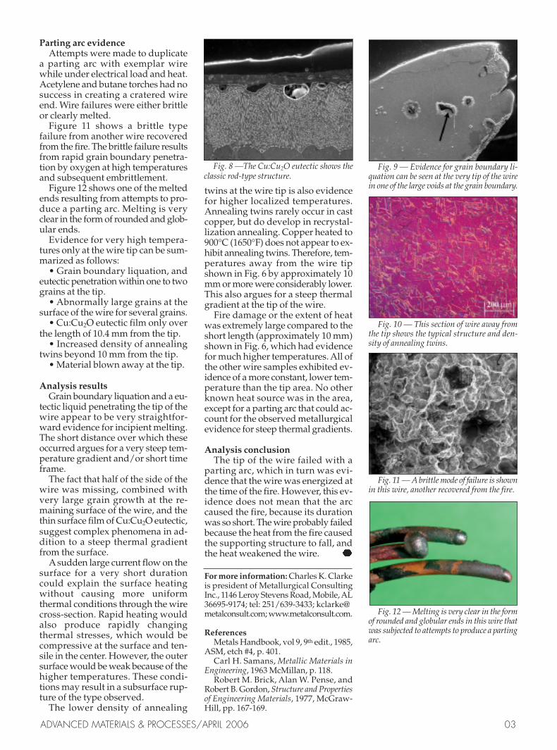
Fig. 8 —The Cu:Cu2O eutectic shows theclassic rod-type structure.
Fig. 12 — Melting is very clear in the formof rounded and globular ends in this wire thatwas subjected to attempts to produce a partingarc.
Fig. 9 — Evidence for grain boundary li-quation can be seen at the very tip of the wirein one of the large voids at the grain boundary.
Fig. 10 — This section of wire away fromthe tip shows the typical structure and den-sity of annealing twins.
Fig. 11 — A brittle mode of failure is shownin this wire, another recovered from the fire.
Related Documents


