ARL Up-gradation of Effluent Wastewater Treatment Plant (ETP Phase-II) A sustainable Environmental Initiative Muhammad Fahad Khan Attock Refinery Ltd.

Welcome message from author
This document is posted to help you gain knowledge. Please leave a comment to let me know what you think about it! Share it to your friends and learn new things together.
Transcript
ARL Up-gradation of Effluent Wastewater Treatment Plant (ETP
Phase-II)
A sustainable Environmental InitiativeMuhammad Fahad
KhanAttock Refinery Ltd.
Introduction
Enhance capacity of effluent treatment system.
Compliance with the National Environment Quality Standards (NEQS), in view of future expansion.
Addition of secondary treatment system.
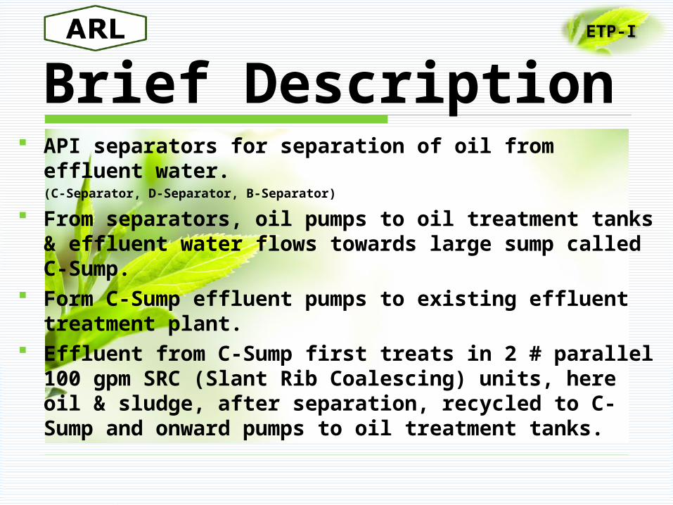
Brief Description API separators for separation of oil from effluent
water. (C-Separator, D-Separator, B-Separator)
From separators, oil pumps to oil treatment tanks & effluent water flows towards large sump called C-Sump.
Form C-Sump effluent pumps to existing effluent treatment plant.
Effluent from C-Sump first treats in 2 # parallel 100 gpm SRC (Slant Rib Coalescing) units, here oil & sludge, after separation, recycled to C-Sump and onward pumps to oil treatment tanks.
ETP-I
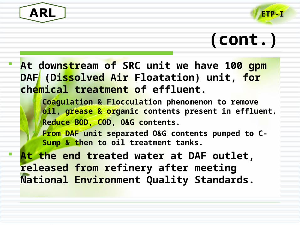
(cont.) At downstream of SRC unit we have 100
gpm DAF (Dissolved Air Floatation) unit, for chemical treatment of effluent.
Coagulation & Flocculation phenomenon to remove oil, grease & organic contents present in effluent.
Reduce BOD, COD, O&G contents. From DAF unit separated O&G contents pumped to
C-Sump & then to oil treatment tanks.
At the end treated water at DAF outlet, released from refinery after meeting National Environment Quality Standards.
ETP-I
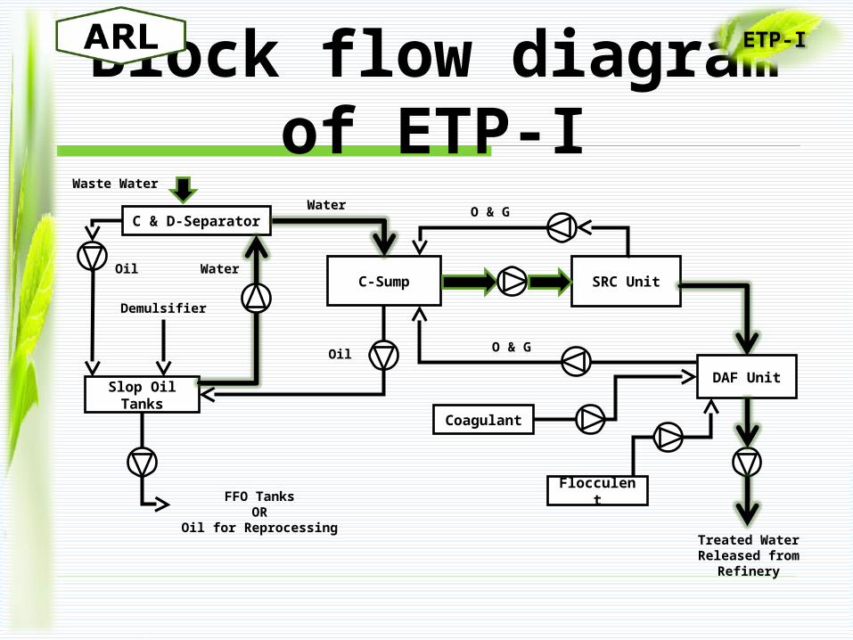
Block flow diagram of ETP-I
ETP-I
SRC Unit
C & D-Separator
Slop Oil Tanks
C-Sump
Waste Water
Oil
Water
Oil O & G
DAF Unit
Treated Water Released from
Refinery
Demulsifier
FFO TanksOR
Oil for Reprocessing
Water
O & G
Coagulant
Flocculent
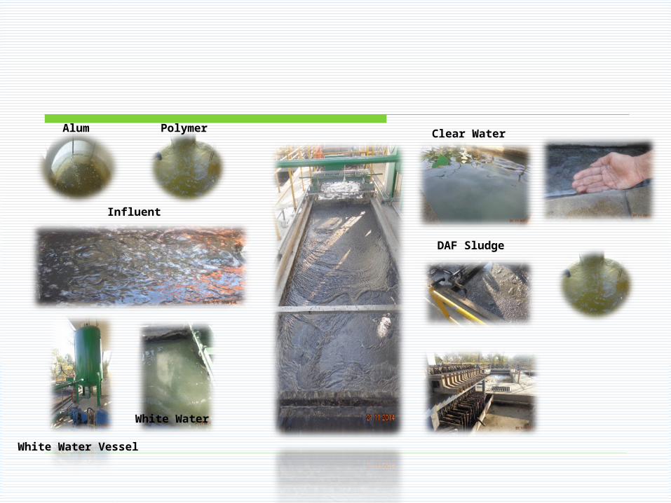
Alum Polymer
Influent
White Water Vessel
White Water
Clear Water
DAF Sludge
Upgraded API Separators
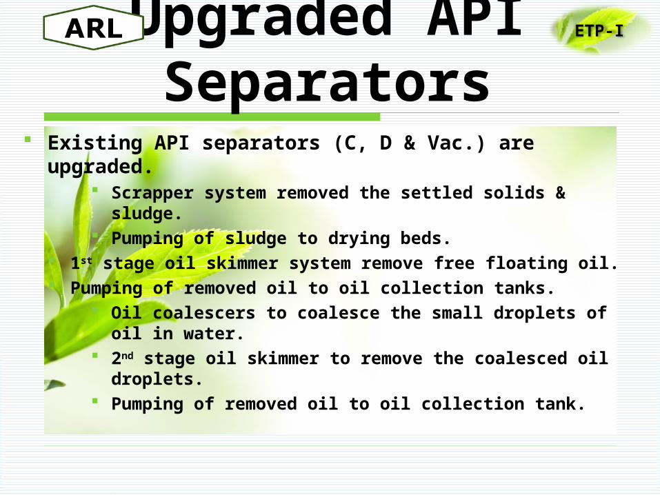
Existing API separators (C, D & Vac.) are upgraded.
Scrapper system removed the settled solids & sludge.
Pumping of sludge to drying beds. 1st stage oil skimmer system remove free floating oil. Pumping of removed oil to oil collection tanks.
Oil coalescers to coalesce the small droplets of oil in water.
2nd stage oil skimmer to remove the coalesced oil droplets.
Pumping of removed oil to oil collection tank.
ETP-I
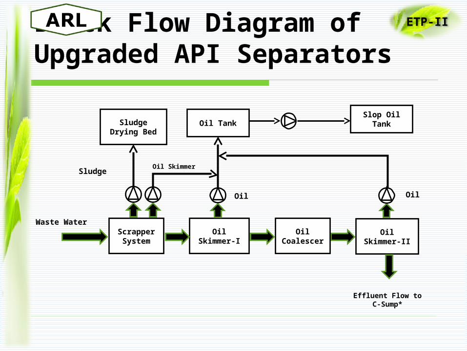
Block Flow Diagram of Upgraded API Separators
ETP-II
Waste WaterScrapper System
Oil Skimmer-I
Sludge Drying Bed
Oil Tank
Oil
Oil Skimmer
Oil Coalescer
Effluent Flow to C-Sump*
Oil Skimmer-II
Oil
Slop Oil Tank
Sludge
ETP-II Section Vise
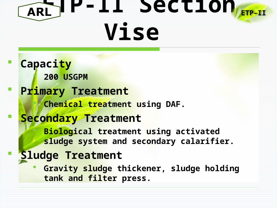
Capacity 200 USGPM
Primary Treatment Chemical treatment using DAF.
Secondary Treatment Biological treatment using activated
sludge system and secondary calarifier.
Sludge Treatment Gravity sludge thickener, sludge holding
tank and filter press.
ETP-II
Primary Treatment
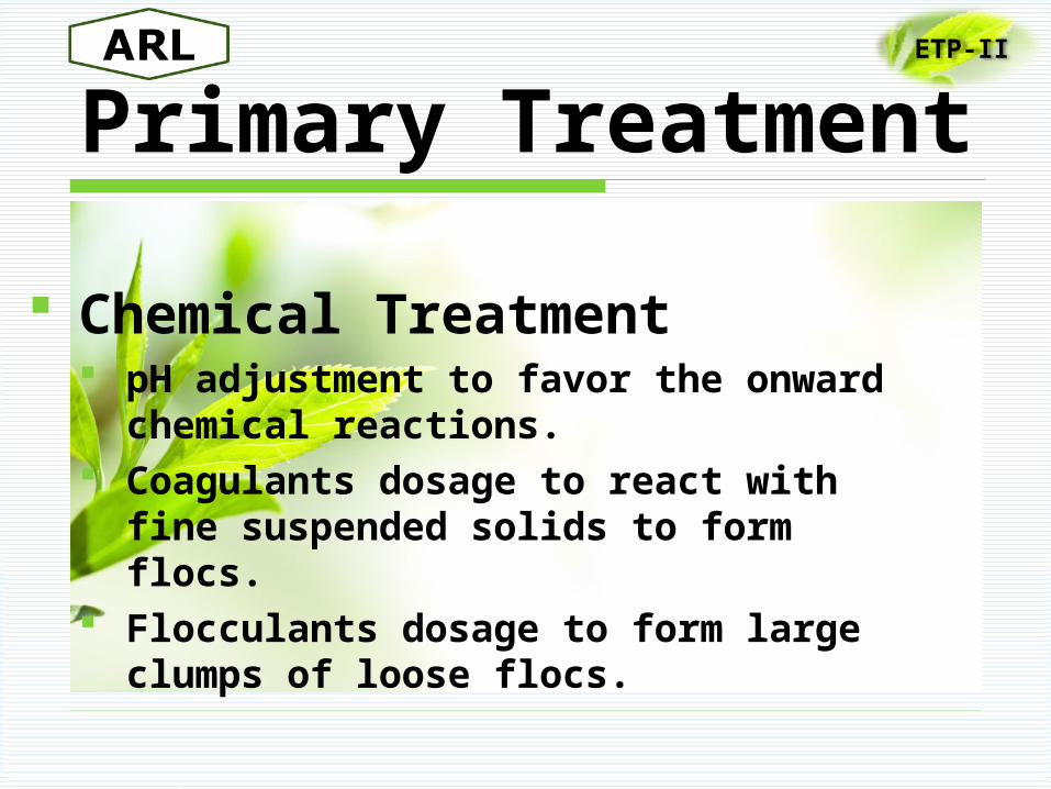
Chemical Treatment pH adjustment to favor the onward
chemical reactions. Coagulants dosage to react with
fine suspended solids to form flocs. Flocculants dosage to form large
clumps of loose flocs.
ETP-II
ETP-II
(cont.)
Dissolved Air Floatation System Removal of generated flocs & suspended
solids. Pressurized water saturated with air
injects to the DAF tank. Fine bubbles formed, attach with flocs and
suspended solids, bring them on surface. Surface particles removed mechanically or
overflowed Removed particles treats as primary
sludge & transferred to filter press.
Secondary Treatment
Biological treatment process.
Aeration Tank Conventional activated sludge system to favor
micro-organism growth. Micro-organisms uptake BOD and COD load
present in wastewater for metabolic growth. Supply of air/oxygen for micro-organism
growth. Maintaining of MLSS (2800 – 3500 mg/l) by
recycling part of activated sludge from secondary clarifier.
ETP-II
ETP-II
(cont.)
Secondary Clarifier Remove the solids by
sedimentation process. Recycle part of sludge to aeration
tank to keep continue the treatment process.
Treated effluent meeting national environment and quality standards, will released from refinery to polishing pond.
Sludge Treatment Sludge collected from secondary
clarifier thickens by filtering the water out of the sludge.
Pumping of reduced volume sludge to sludge holding tank.
Filter press will use to eliminate the moisture content of sludge up to 30 % and to produce cake.
ETP-II
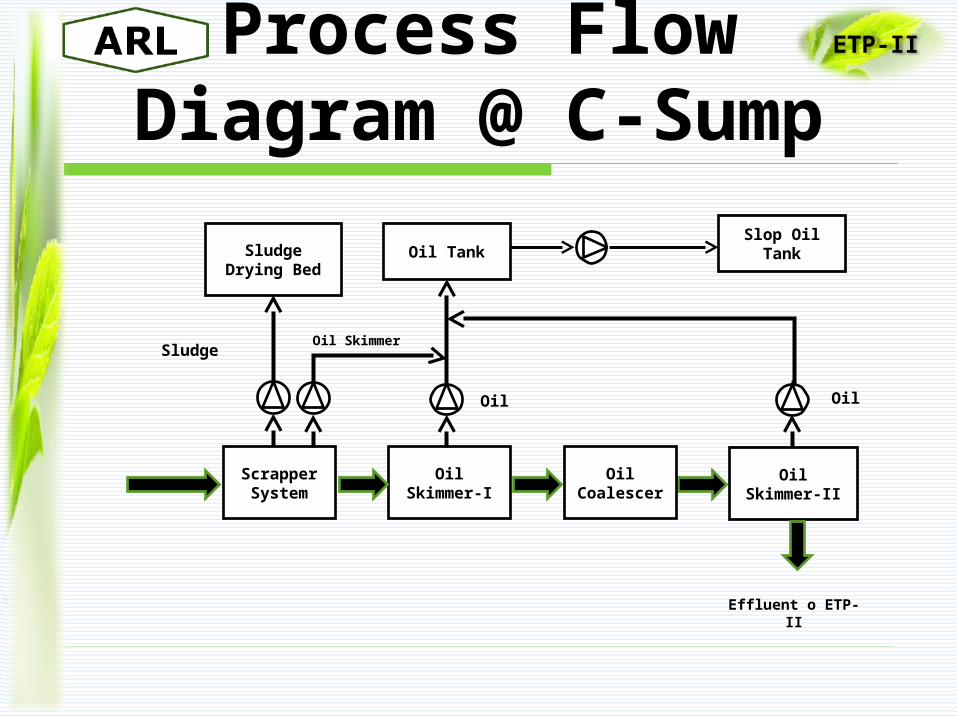
Process Flow Diagram @ C-Sump
ETP-II
Scrapper System
Oil Skimmer-I
Sludge Drying Bed
Oil Tank
Oil
Oil Skimmer
Oil Coalescer
Effluent o ETP-II
Oil Skimmer-II
Oil
Slop Oil Tank
Sludge
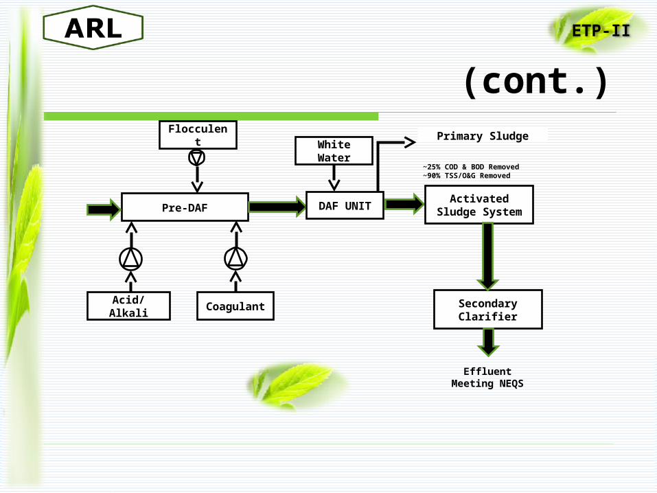
(cont.)
ETP-II
Effluent Meeting NEQS
Pre-DAF
Acid/Alkali
Flocculent
Coagulant
DAF UNIT
White Water
Primary Sludge
~25% COD & BOD Removed~90% TSS/O&G Removed
Activated Sludge System
Secondary Clarifier
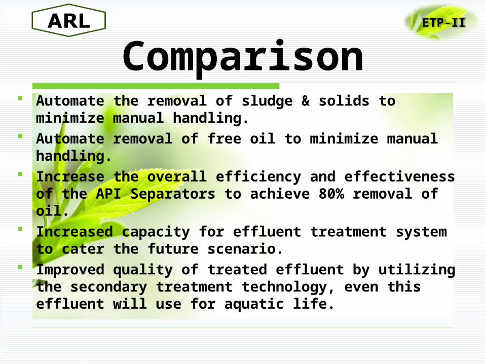
Comparison Automate the removal of sludge & solids to
minimize manual handling. Automate removal of free oil to minimize manual
handling. Increase the overall efficiency and effectiveness
of the API Separators to achieve 80% removal of oil.
Increased capacity for effluent treatment system to cater the future scenario.
Improved quality of treated effluent by utilizing the secondary treatment technology, even this effluent will use for aquatic life.
ETP-II
THANKS Q . . . ?
Related Documents