Feature Coding Standards and Geodatabase Design An ESRI ® Technical Paper • October 2002 ESRI 380 New York St., Redlands, CA 92373-8100, USA • TEL 909-793-2853 • FAX 909-793-5953 • E-MAIL [email protected] • WEB www.esri.com

Welcome message from author
This document is posted to help you gain knowledge. Please leave a comment to let me know what you think about it! Share it to your friends and learn new things together.
Transcript

8/3/2019 ESRI Feature Coding Standards and Geodatabase Design
http://slidepdf.com/reader/full/esri-feature-coding-standards-and-geodatabase-design 1/40
Feature Coding Standards and Geodatabase
Design An ESRI ® Technical Paper • October 2002
ESRI 380 New York St., Redlands, CA 92373-8100, USA • TEL 909-793-2853 • FAX 909-793-5953 • E-MAIL [email protected] • WEB www.esri.com

8/3/2019 ESRI Feature Coding Standards and Geodatabase Design
http://slidepdf.com/reader/full/esri-feature-coding-standards-and-geodatabase-design 2/40
Copyright © 2002 ESRIAll rights reserved.Printed in the United States of America.
The information contained in this document is the exclusive property of ESRI. This work is protected under UnitedStates copyright law and other international copyright treaties and conventions. No part of this work may bereproduced or transmitted in any form or by any means, electronic or mechanical, including photocopying andrecording, or by any information storage or retrieval system, except as expressly permitted in writing by ESRI. Allrequests should be sent to Attention: Contracts Manager, ESRI, 380 New York Street, Redlands, CA 92373-8100,USA.
The information contained in this document is subject to change without notice.
U.S. GOVERNMENT RESTRICTED/LIMITED RIGHTSAny software, documentation, and/or data delivered hereunder is subject to the terms of the License Agreement. In noevent shall the U.S. Government acquire greater than RESTRICTED/LIMITED RIGHTS. At a minimum,use, duplication, or disclosure by the U.S. Government is subject to restrictions as set forth in FAR §52.227-14Alternates I, II, and III (JUN 1987); FAR §52.227-19 (JUN 1987) and/or FAR §12.211/12.212 (CommercialTechnical Data/Computer Software); and DFARS §252.227-7015 (NOV 1995) (Technical Data) and/or DFARS§227.7202 (Computer Software), as applicable. Contractor/Manufacturer is ESRI, 380 New York Street, Redlands,CA 92373-8100, USA.
ESRI, ARC/INFO, ArcCAD, ArcIMS, ArcView, BusinessMAP, MapObjects, PC ARC/INFO, SDE, the ESRI globe
logo, 3D Analyst, ADF, the ARC/INFO logo, AML, ArcNews, ArcTIN, the ArcTIN logo, ArcCOGO, the ArcCOGOlogo, ArcGrid, the ArcGrid logo, ArcInfo, the ArcInfo logo, ArcInfo Librarian, ArcInfo—Professional GIS, ArcInfo—The World’s GIS, ArcAtlas, the ArcAtlas logo, the ArcCAD logo, the ArcCAD WorkBench logo, ArcCatalog, theArcData logo, the ArcData Online logo, ArcDoc, ArcEdit, the ArcEdit logo, ArcEditor, ArcEurope, the ArcEuropelogo, ArcExplorer, the ArcExplorer logo, ArcExpress, the ArcExpress logo, ArcFM, the ArcFM logo, the ArcFMViewer logo, ArcGIS, the ArcGIS logo, the ArcIMS logo, ArcNetwork, the ArcNetwork logo, ArcLogistics, theArcLogistics Route logo, ArcMap, ArcObjects, ArcPad, the ArcPad logo, ArcPlot, the ArcPlot logo, ArcPress, theArcPress logo, the ArcPress for ArcView logo, ArcReader, ArcScan, the ArcScan logo, ArcScene, the ArcScene logo,ArcSchool, ArcSDE, the ArcSDE logo, the ArcSDE CAD Client logo, ArcSdl, ArcStorm, the ArcStorm logo,ArcSurvey, ArcToolbox, ArcTools, the ArcTools logo, ArcUSA, the ArcUSA logo, ArcUser, the ArcView logo, theArcView GIS logo, the ArcView 3D Analyst logo, the ArcView Business Analyst logo, the ArcView Data Publisherlogo, the ArcView Image Analysis logo, the ArcView Internet Map Server logo, the ArcView Network Analyst logo,the ArcView Spatial Analyst logo, the ArcView StreetMap logo, the ArcView StreetMap 2000 logo, the ArcViewTracking Analyst logo, ArcVoyager, ArcWorld, the ArcWorld logo, Atlas GIS, the Atlas GIS logo, AtlasWare,Avenue, the Avenue logo, the BusinessMAP logo, the Data Automation Kit logo, Database Integrator, DBI Kit, the
Digital Chart of the World logo, the ESRI Data logo, the ESRI Press logo, ESRI—Team GIS, ESRI—The GIS People,FormEdit, Geographic Design System, Geography Matters, GIS by ESRI, GIS Day, GIS for Everyone, GISDataServer, InsiteMAP, MapBeans, MapCafé, the MapCafé logo, the MapObjects logo, the MapObjects Internet MapServer logo, ModelBuilder, MOLE, the MOLE logo, NetEngine, the NetEngine logo, the PC ARC/INFO logo,PC ARCEDIT, PC ARCPLOT, PC ARCSHELL, PC DATA CONVERSION, PC NETWORK, PC OVERLAY,PC STARTER KIT, PC TABLES, the Production Line Tool Set logo, RouteMAP, the RouteMAP logo, the
RouteMAP IMS logo, Spatial Database Engine, the SDE logo, SML, StreetEditor, StreetMap, TABLES, The World’sLeading Desktop GIS, Water Writes, Your Personal Geographic Information System, ArcData, ArcOpen, ArcQuest,
ArcWatch, ArcWeb, Rent-a-Tech, Geography Network, the Geography Network logo, www.geographynetwork.com,www.gisday.com, @esri.com, and www.esri.com are trademarks, registered trademarks, or service marks of ESRI inthe United States, the European Community, or certain other jurisdictions.
Other companies and products mentioned herein are trademarks or registered trademarks of their respective trademark owners.

8/3/2019 ESRI Feature Coding Standards and Geodatabase Design
http://slidepdf.com/reader/full/esri-feature-coding-standards-and-geodatabase-design 3/40
Feature Coding Standards and
Geodatabase Design
An ESRI Technical Paper
Contents
Introduction 1 Feature coding standards 1 The need for a smart geodatabase design 3
What are valid value tables? 6 The enhanced VVT design 6 The VVT design and geodatabase data models 7 Building VVTs for existing data models 7
A case study: the DIGEST feature coding standard 8
Applying the DIGEST standard to the geodatabase design 8 Detailed database design 9
Sample ArcGIS application extension 12 Managing the application extension 13 Specifying DIGEST coding criteria for various operations 15 Selecting features 19 Layer definition queries 23 Rendering features 24 Creating and editing features 25 Exporting features 33
ESRI Technical Paper i

8/3/2019 ESRI Feature Coding Standards and Geodatabase Design
http://slidepdf.com/reader/full/esri-feature-coding-standards-and-geodatabase-design 4/40
Feature Coding Standards and Geodatabase Design
October 2002 ii

8/3/2019 ESRI Feature Coding Standards and Geodatabase Design
http://slidepdf.com/reader/full/esri-feature-coding-standards-and-geodatabase-design 5/40

8/3/2019 ESRI Feature Coding Standards and Geodatabase Design
http://slidepdf.com/reader/full/esri-feature-coding-standards-and-geodatabase-design 6/40
Feature Coding Standards and Geodatabase Design
The application of a coding standard can be independent of a specific data product or
specification, and in fact, any geographic feature in any database can be assigned somemajor and minor codes based on a coding standard. The code is also independent of the
representation of a feature in the GIS (as a point, line, or polygon). For example, a school
as an image, a school as a point, a school as a polygon, and a school as a row in a table all
share the same major and minor codes.
The codes associated with features are important to users of the geographic database.
Organizations that assign meaning to their features using coding standards also wish to
query their database and assign meaning to their features while editing based on these
codes. The requirement for using these codes for working with a geographic database can
be summarized as:
Selection: Users need the ability to select features in a feature class, not only by the
attributes that describe individual features (such as the name of a road or the volume of alake) but also in terms of feature classification described by these coding standards. For
example, “select all features in the WaterLines feature class that are aqueducts and are
suspended above the ground and known to be operational”.
Specifying definition queries: Like making selections, users need the ability to specify a
layer definition query on both the attributes that describe individual features and by the
feature classification described by the coding standard. For example, “draw only those
features from the TransportationLine feature class that represent roads that are paved,
have medians, are known to be operational, and whose location is known to be accurate”.
Rendering features: Users need to be able to assign symbols for drawing based on
classifications as described in the coding standard. For example, “when drawing the
TransportationLines feature class, draw RailRoads with black lines, Roads that are pavedwith red lines, and Roads that are not paved in dashed red lines”.
Editing and creating new features: When creating new features, users must be able to
associate the meaning of the feature in terms of the coding standard. Likewise, when
updating an existing feature’s classification, they need to be able to assign relevant codes
to the feature. While there are potentially thousands of possible combinations of major
and minor codes in any coding system, in reality there is a much smaller subset of valid
code combinations that actually exist in the database. Users need to be able to assign
major and minor codes to their features but be prevented from assigning invalid code
combinations. For example, a user should be able to “create a new road that is paved and
has a median” but may not be able to “create a new road that is dirt and has a median”.
Data extraction: The extraction of data from any database is important to provide to other
organizations or for use in applications that require data in some particular format. Users
need to be able to export features from their database into other formats and carry the
feature codes with the features in that exported format.
As with any database design, the database must perform well in a multiuser reading and
editing environment.
October 2002 2

8/3/2019 ESRI Feature Coding Standards and Geodatabase Design
http://slidepdf.com/reader/full/esri-feature-coding-standards-and-geodatabase-design 7/40
Feature Coding Standards and Geodatabase Design
The remainder of this technical paper describes the geodatabase design pattern and
ArcGIS application extension to support coding standards, specifically the requirementsabove. A specific geodatabase design that supports the DIGEST coding standard is used
as a case study.
The need for a smartgeodatabase design
The classification code describing a feature can be considered as an attribute of the
feature. It is a complex attribute because it consists of a major code and one or more
minor codes, but it is, logically, a single property. This property value is drawn from a
domain of possible values defined in the coding standard. A set of line features, with
their code, could be modeled like this:
Id geometry code101 xy...xy BH140,hyc=6102 xy...xy BH140,hyc=8
103 xy...xy BH020,hyc=8,exs=32... ... ...
1 0 3
1 0 2
1 0 1
Where, for feature 103, BH020 is the major code, hyc and exs are the minor codes.
In this case, the feature class represents a drainage network of rivers, streams, and canals.
Each drainage network element is coded with the appropriate feature code.
As this example illustrates, coding standards define a standard for assigning meaning to
features, but they do not dictate any particular organization of features into classes or the
actual structure of the geographic data model. In particular, it is not necessary that the
logical or physical schema of a geodatabase design reflect the logical structure of the
coding standard. Major codes do not define feature classes; minor codes do not define
ESRI Technical Paper 3

8/3/2019 ESRI Feature Coding Standards and Geodatabase Design
http://slidepdf.com/reader/full/esri-feature-coding-standards-and-geodatabase-design 8/40
Feature Coding Standards and Geodatabase Design
feature class fields. The only requirement is that we can associate a code or description
with any feature represented in the database.
One could take the approach where the major codes are mapped to feature classes and the
minor code to fields. This leads to a database design that has a large number of feature
classes that won’t perform well. To reduce the number of feature classes, one might lump
major codes with similar minor codes into a single feature class. This results in a feature
class containing many features with Null values for those minor code fields that do not
apply to the major code.
This is not a good GIS design. Coding standards are only standards for describing
features; they do not dictate how features are identified or organized in the GIS. In fact, it
is a poor idea to let the descriptive logic of a coding standard control the spatial or
functional logic of the GIS data model. Other aspects, such as the geographic
representation of features (lines organized in a network, areas that share topology, etc.),the need to model real-world objects, or the feature extraction specifications, are more
important factors to consider in defining feature classes in our geodatabase design. For
many datasets in the data model, the descriptive code will be simply irrelevant—for
example, bathymetry mass points, military unit overlays, and satellite tracks. For the
others, the requirement is simply to be able to get the code for any feature.
The goal is to provide a general mechanism for associating codes with features and use
these codes to control map display. This introduces the need for tools to edit the codes,
among other things, but the coding standard should not be used to control the data model
design.
October 2002 4

8/3/2019 ESRI Feature Coding Standards and Geodatabase Design
http://slidepdf.com/reader/full/esri-feature-coding-standards-and-geodatabase-design 9/40
Feature Coding Standards and Geodatabase Design
There are several approaches to such a geodatabase design:
The direct approach: major codes map to feature classes, while minor codes map to
fields. Minor codes vary with subtypes, allowing you to group multiple major codes
into a single feature class.
Simple feature classWaterL Contains Z values
Contains M valuesGeometry Polyline
NoNo
Data typeField namePreci-sion Scale LengthDomain
Defaultvalue
Allownulls
OBJECTID OID
Shape Geometry Yes
FCSUBTYPE Integer Yes 0
GFID String Yes 38
VVTID Integer Yes 0
SOURCE Integer Yes 0
NAM String Yes 254OHC Integer Yes 0
WID Integer Yes 0
MaxDepth Double Yes 0 0
F_CODE String Yes 6 Major code
ACC Integer Yes 0 0 2
SLT Integer Yes 0 0 2
VDC Integer Yes 0 0 2
EXS Integer Yes 0 0 2
HYC Integer Yes 0 0 2
TID Integer Yes 0 0 2
ATC Integer Yes 0 0 2
LOC Integer Yes 0 0 2
HFC Integer Yes 0 0 2
Shape_Length Double Yes 0 0
Minor codes
The fully normalized approach: fully normalized attribute model where multipleminor code records for each feature are stored in a related table.
The enhanced valid value table (VVT) approach: create a table of valid major and
minor code combinations representing the actual content of the database (it is not
necessary to list all possible combinations of minor and major codes). Build a
relationship to associate features with codes through foreign keys into this table.
TableWaterLines_VVT
Data typeField namePreci-sion Scale LengthDomain
Defaultvalue
Allownulls
OBJECTID OID
FACC String Yes 255
Description String Yes 250
VVTID Integer Yes 0
ACODES String Yes 255
Simple feature classWaterLines
Geometry Polyline
Data typeField namePreci-sion Scale LengthDomain
Defaultvalue
Allownulls
OBJECTID OID
VVTID Integer Yes 0
Width Double Yes
Shape Geometry Yes
Shape_Length Double Yes 0 0
0 0
The direct approach is not a good design for the reasons discussed earlier, and the fully
normalized model is also not a good design as it would result in too many records in the
minor code table and require complex query processing. The VVT approach is a good
database design because it best reflects the logic of the coding standard; it compresses the
data representation to only deal with valid combinations and supports quality assurance
(QA), editing, mapping/query, and multipurpose GIS use.
ESRI Technical Paper 5

8/3/2019 ESRI Feature Coding Standards and Geodatabase Design
http://slidepdf.com/reader/full/esri-feature-coding-standards-and-geodatabase-design 10/40
Feature Coding Standards and Geodatabase Design
What are valid value
tables?
Valid value tables are tools used to perform quality assurance and to help users who
maintain databases assign valid meaning to their features. The VVT contains informationas to the valid combinations of major and minor codes for how a particular coding
standard is defined for a particular database.
The geodatabase design presented here for databases whose features’ meanings are
defined by feature codes uses the VVT concept in a more direct way: the VVT is not only
used as a QA tool but is also used to hold the coding information for the features.
The enhanced VVTdesign
As discussed at the beginning of this section, the classification code describing a feature
can be considered an attribute of the feature. It’s a complex attribute as it consists of a
major code and one or more minor codes but is logically a single property. The enhanced
VVT design uses the VVT itself to store the coding information for the features, while
the features themselves hold a foreign key reference to the row in the VVT that contains
the major and minor code combination for that feature.
In this design, the codes themselves are treated like an attribute that has a special kind of
attribute domain, or a complex domain. The components of a feature’s code can be
presented to the user by displaying and allowing them to manipulate this foreign key
reference attribute as its component parts. The VVT itself contains references to data
dictionary tables in the geodatabase that give real, descriptive meaning to the codes.
Selection, inspection, and editing of the feature code involve looking up the full code in
the VVT and presenting it in a user interface. These user interfaces can present a set of
choices based on either (a) picking an existing valid combination or (b) picking
individual minor code values. The actual structure of the database is invisible to the end
user.
This leads to the question: What is the best VVT design for this purpose? There are a
number of possibilities:
Should there be multiple VVTs (one for each feature class) or a single centralized
VVT?
Represent the structure of the VVTs as:
• A single table with one column for each minor code.
• A single table with minor codes appended in a string field.
• A normalized table with multiple records for each minor code and corresponding
valid value property.
In this geodatabase design, a VVT table has been created for each feature class in the
database. The VVT contains one field for the major code and one field for the minor
codes, which are appended in a string. The approach of a single field containing a string
with all the minor code/value pairs simplifies the application logic and queries: each
VVT can be queried in a generic way, always returning the same number of fields
October 2002 6

8/3/2019 ESRI Feature Coding Standards and Geodatabase Design
http://slidepdf.com/reader/full/esri-feature-coding-standards-and-geodatabase-design 11/40
Feature Coding Standards and Geodatabase Design
regardless of the number of minor codes. The string can then be parsed and analyzed by
the application. An example of a feature class in this geodatabase is below:
TableWaterLines_VVT
Data typeField namePreci-sion Scale LengthDomain
Defaultvalue
Allownulls
OBJECTID OID
FACC String Yes 255
Description String Yes 250
VVTID Integer Yes 0
ACODES String Yes 255
Simple feature classWaterLines
Geometry Polyline
Data typeField namePreci-sion Scale LengthDomain
Defaultvalue
Allownulls
OBJECTID OID
VVTID Integer Yes 0
Width Double Yes
Shape Geometry Yes
Shape_Length Double Yes 0 0
0 0
Each feature class (in this case the WaterLines feature class) has a VVT (in this case
WaterLines_VVT), and the two are joined based on the ID of the valid value (VVTID).
The major code in the VVT is FACC. The minor codes are held in the ACODES field.
The VVT design andgeodatabase datamodels
ESRI has been actively involved with its user community in the development of a seriesof ArcGIS data models, which are intended to provide a common design framework for
key layers of GIS information. These design efforts have resulted in a series of
comprehensive design specifications for a number of thematic layers, including:
Census and Administrative Units (applied to U.S. Census geography)
Topographic Base Maps for 1:24,000-Scale Maps
Hydrography
Raster Imagery and Elevation Catalogs
Streets and Comprehensive Address Information
Transportation (to support linear referencing, navigation, addressing, and
cartography)
Federal Lands and the Public Land Survey System (PLSS) (to support a national
database of the legal survey fabric)
Parcels (to support both U.S. and worldwide systems)
Water Facilities
Numerous Other Efforts
Building VVTs forexisting data models
The VVT design principles presented here can apply for coding any of these data models
or a geodatabase data model that you may design in your organization.
The geodatabase design for VVTs presented in this technical paper centers on the
maintenance of a single attribute in any of the feature classes present in the data models
listed above or in the data model you have designed based on the GIS requirements of
ESRI Technical Paper 7

8/3/2019 ESRI Feature Coding Standards and Geodatabase Design
http://slidepdf.com/reader/full/esri-feature-coding-standards-and-geodatabase-design 12/40
Feature Coding Standards and Geodatabase Design
your organization. The incorporation of feature coding information should be a
complement to any of these geodatabase data models, not the basis for a new data model.
The remainder of this technical paper presents a case study and sample geodatabase,
including a sample ArcGIS application extension that interprets the feature coding
information in the geodatabase and presents that information to the user.
A case study: theDIGEST featurecoding standard
The first implementation of this database design on a real coding standard was built to
support the DIGEST coding standard. This section of the technical paper will tie the data
modeling concepts already discussed into DIGEST coding terms. A sample geodatabase
and sample application extension that work with this geodatabase are described in the
next section.
Like other coding standards, the DIGEST standard defines a system for associating
meaning with geographic features. The standard is based on a set of feature codes, whichcan then be further modified by other parameters. For example, an intermittent stream
would be described as “River/Stream, hydrological category = intermittent”
(BH140,hyc=6). A church would be described as “Building, function = house of worship,
house of worship type = church” (AL015,bfc=7,hwt=4). In DIGEST, the major code
(e.g., BH140) is called the FCODE, while the minor codes are called ACODEs (e.g.,
hyc=6).
Vector product format (VPF) product designs, such as Vector Map Level 2 (VMap 2) and
Topographic Line Map (TLM), were heavily influenced by the DIGEST logical structure.
ACODEs were mapped to VPF fields and FCODEs to feature tables. To reduce the
number of feature tables, multiple FCODEs that share similar ACODE fields were
combined in a single table.
To learn more about the DIGEST coding standard, refer to www.digest.org.
Applying theDIGEST standard to
the geodatabasedesign
The basic design of a geodatabase that supports the DIGEST coding standard, as
described in the previous sections of this technical paper, implies that the underlying
storage of the coding information is not the user’s view of the data and special tools are
required to present and work with the coding information stored in the geodatabase.
Each feature class in this data model contains its geometry, range attributes, and an ID
that maps it to a row in a VVT. The contents of this row are the DIGEST attributes for
classifying features (FCODE and various ACODEs). The VVT also contains the
description of the combination of FCODE and ACODEs. The user-consumable
descriptions of these FCODEs and ACODEs are stored in a set of data dictionary tables.
October 2002 8

8/3/2019 ESRI Feature Coding Standards and Geodatabase Design
http://slidepdf.com/reader/full/esri-feature-coding-standards-and-geodatabase-design 13/40
Feature Coding Standards and Geodatabase Design
Applications that work with this data model need to understand the structure of the
database, navigate the feature class/VVT relationship, and use the data dictionary tablesto provide the user with a meaningful representation of the feature codes.
Applications
Feature Class,
Feature Class VVT
Object Inspector
Query Tool
Renderer
DIGEST Data Dictionary
Tables
Detailed databasedesign
Each feature class has its own VVT, and there are three data dictionary tables that contain
the FCODEs, ACODEs, and their descriptions. The remainder of this section describes
the table structure and its contents in more detail.
Each feature class has a corresponding VVT named <Feature Class>_VVT. For example,
the WaterL feature class has a VVT called WaterL_VVT. The VVT has a primary key
(VVTID), and the feature class has the embedded foreign key (VVTID). These keys are
used to determine which DIGEST code combination each feature is associated with in thefeature class.
The database also contains a set of tables for which there is a single copy in the database:
FCODES, ATTDESC, and ATTVAL. The FCODES table contains information on each
FCODE, such as its description, the ACODEs that apply to it, and the allowable values
for each ACODE for that FCODE. The primary key is the FCODE, and each VVT has an
embedded foreign key called FCODE on which these tables are joined.
ESRI Technical Paper 9

8/3/2019 ESRI Feature Coding Standards and Geodatabase Design
http://slidepdf.com/reader/full/esri-feature-coding-standards-and-geodatabase-design 14/40
Feature Coding Standards and Geodatabase Design
The ATTDESC and ATTVAL tables contain descriptions for what each ACODE is as
well as descriptions for what each value of each ACODE means, respectively. Thisstructure is illustrated below.
TableWaterLines_VVT
Data typeField namePreci-sion Scale LengthDomain
Defaultvalue
Allownulls
OBJECTID OID
FACC String Y es 255
Description String Yes 250
VVTID Integer Yes 0
ACODES String Yes 255
Simple feature classWaterLines
Geometry Polyline
Data typeField namePreci-sion Scale LengthDomain
Defaultvalue
Allownulls
OBJECTID OID
VVTID Integer Yes 0
Width Double Yes
Shape Geometry Yes
Shape_Length Double Yes 0 0
TableATTVAL
Data typeField namePreci-sion Scale LengthDomain
Defaultvalue
Allownulls
ID OID
Attribute String Yes 255
Value_ Integer Yes 0
Description String Yes 255
Units String Y es 50
Format String Yes 50
Range String Y es 50
Increment String Yes 50
Maximum_Characters String Yes 50
TableATTDESC
Data typeField namePreci-sion Scale LengthDomain
Defaultvalue
Allownulls
OBJECTID OID
Attribute String Yes 255
Short_Description String Yes 255
Description String Yes 50
TableFCODES
Data typeField name Preci-sion Scale LengthDomainDefaultvalueAllownulls
FACC String Yes 255
Description String Yes 50
English String Yes 255
French String Yes 255
German String Yes 255
Italian String Yes 255
Dutch String Yes 255
Spanish String Yes 255
Danish String Yes 255
ACODES String Yes 255
OBJECTID OID
0 0
The valid value tables Each VVT has the same structure: a field that stores the FCODE, a field that stores the
ACODEs and their values as a string, and a field that stores the text description of the
valid value combination. An example VVT is illustrated below:
TableWaterLines_VVT
Data typeField namePreci-sion Scale LengthDomain
Defaultvalue
Allownulls
OBJECTID OID
FACC String Yes 255
Description String Yes 250
VVTID Integer Yes 0
ACODES String Yes 255
The name of the FCODE
The long description of the valid value combination
The unique ID for the valid value combination
The ACODEs and their values
October 2002 10

8/3/2019 ESRI Feature Coding Standards and Geodatabase Design
http://slidepdf.com/reader/full/esri-feature-coding-standards-and-geodatabase-design 15/40
Feature Coding Standards and Geodatabase Design
Storing the ACODEs and their values in a single field as a string has many advantages:
all VVTs can be queried in the same way, regardless of the number of ACODEsassociated with the FCODE; the queries are more efficient in that only the same small
number of fields is returned each time the VVT is queried. An example of a VVT is
shown below:
VVTID F_CODE Description ACODES
1 BA010 Coastline/Shoreline - Definite... ACC 1|SLT 0|VDC 0|
2 BA010 Coastline/Shoreline - Approximate... ACC 2|SLT 0|VDC 15|
3 BH020 Canal - Abandoned/Disused... EXS 6|HYC 0|TID -9|
4 BH020 Canal - Navigable - Perennial... EXS 32|HYC 8|TID -9|
Application logic is required to interpret this string and to construct queries based on thisstring format. The details of this are discussed in the next section of this technical paper.
The DIGEST dictionary tables
There are three tables that contain the DIGEST dictionary information: FCODES,
ATTDESC, and ATTVAL. These tables are used by the application extension to provide
useful, descriptive information for users to interact with.
The FCODES table describes each FCODE and the list of ACODEs and their values that
are applicable to the FCODE. The list of applicable ACODEs and their values is
important for providing a usable interface for users to define a query on any particular
FCODE.
For example, the EXS (existence category) ACODE applies to both the FCODEs BH010
(Canal) and AL240 (Tower); the allowable values for that ACODE differ for theseFCODEs, as do the other applicable ACODEs.
Like in the VVT, the ACODEs and their values are stored as strings. An excerpt from the
FCODES table is shown below:
F_CODE Description ACODES
BA010 Aqueduct ATC[0,1];EXS[28,5];LOC[0,25,4,8]
BA020 Canal EXS[6,32];HYC[0,8];TID[-9]
DB170 Sand Dune/Sand Hills SSC[30,22,0,28,27,26,29]
GB010 Airport Lighting EXS[-9];LFA[10,26,53,0]
ESRI Technical Paper 11
8/3/2019 ESRI Feature Coding Standards and Geodatabase Design
http://slidepdf.com/reader/full/esri-feature-coding-standards-and-geodatabase-design 16/40
Feature Coding Standards and Geodatabase Design
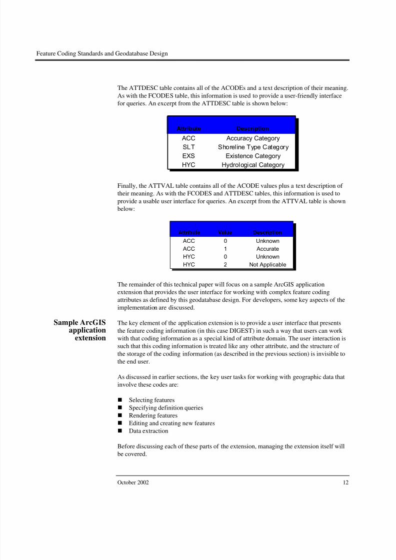
The ATTDESC table contains all of the ACODEs and a text description of their meaning.
As with the FCODES table, this information is used to provide a user-friendly interfacefor queries. An excerpt from the ATTDESC table is shown below:
Attribute Description
ACC Accuracy Category
SLT Shoreline Type Category
EXS Existence Category
HYC Hydrological Category
Finally, the ATTVAL table contains all of the ACODE values plus a text description of
their meaning. As with the FCODES and ATTDESC tables, this information is used toprovide a usable user interface for queries. An excerpt from the ATTVAL table is shown
below:
Attribute Value Description
ACC 0 Unknown
ACC 1 Accurate
HYC 0 Unknown
HYC 2 Not Applicable
The remainder of this technical paper will focus on a sample ArcGIS application
extension that provides the user interface for working with complex feature codingattributes as defined by this geodatabase design. For developers, some key aspects of the
implementation are discussed.
Sample ArcGISapplication
extension
The key element of the application extension is to provide a user interface that presents
the feature coding information (in this case DIGEST) in such a way that users can work
with that coding information as a special kind of attribute domain. The user interaction is
such that this coding information is treated like any other attribute, and the structure of
the storage of the coding information (as described in the previous section) is invisible to
the end user.
As discussed in earlier sections, the key user tasks for working with geographic data that
involve these codes are:
Selecting features
Specifying definition queries
Rendering features
Editing and creating new features
Data extraction
Before discussing each of these parts of the extension, managing the extension itself will
be covered.
October 2002 12

8/3/2019 ESRI Feature Coding Standards and Geodatabase Design
http://slidepdf.com/reader/full/esri-feature-coding-standards-and-geodatabase-design 17/40
Feature Coding Standards and Geodatabase Design
For developers, some key aspects of the implementation are discussed, including the
navigation of the table structure described in the previous sections.
Managing theapplication extension
Once installed, the extension can be turned on in ArcMap™ like any other ArcGIS
extension:
1. On the main menu, click Tools and click Extensions.2. In the Extensions dialog box, check the Feature Coding Extension to activate it.3. Click Close to dismiss the dialog box.
ESRI Technical Paper 13

8/3/2019 ESRI Feature Coding Standards and Geodatabase Design
http://slidepdf.com/reader/full/esri-feature-coding-standards-and-geodatabase-design 18/40
Feature Coding Standards and Geodatabase Design
Once the map extension is activated, you must tell the extension where your feature code
tables are located and some information about which fields in those tables to use toaccess the data dictionary information.
1. On the main menu, click Tools and click Options.
2. In the Options dialog box, check the Feature Coding Extension tab.
3. Click the Browse button to navigate to the geodatabase that contains the datadictionary table (note: the data dictionary tables can be located in a differentgeodatabase from the feature data).
4. Click the dropdown boxes to specify the tables and their fields that correspond to thevarious elements of the data dictionary (see the image below to understand whichcombo boxes are related to which dictionary component).
5. Click OK to apply your changes and close the dialog box.
This information is written to the Windows®
registry, so the next time you activate the
extension, you won’t have to specify this information again.
October 2002 14

8/3/2019 ESRI Feature Coding Standards and Geodatabase Design
http://slidepdf.com/reader/full/esri-feature-coding-standards-and-geodatabase-design 19/40
Feature Coding Standards and Geodatabase Design
For developers:
When the information in this dialog box is applied, the application extension does severalthings:
First, it opens the data dictionary tables specified in the dialog box. Since the minor codetable (ATTDESC) and the minor code value table (ATTVAL) are both relatively small,and the information in them is accessed frequently by the extension, the contents of thesetables are cached in memory as Visual Basic
®dictionary objects. Caching this
information allows fast access and greatly reduces the number of queries executed in thedatabase as the user performs a variety of operations.
The information provided in the dialog box is also written to the Windows registry. Thisallows for these parameters to be persisted across ArcMap sessions and eliminates theneed to specify this information each time the extension is activated. This information is
persisted in registry as strings for the table and fields names and as a binary registry valuefor the workspace name object. When the extension is activated, it reads this informationfrom the registry if present.
Specifying DIGESTcoding criteria forvarious operations
The user interface for selecting, symbolizing, and applying layer definition queries needs
to provide a way for users to specify their criteria based on the FCODE and ACODEs
that apply to the features in a particular feature class. Since the VVTs hold only those
real combinations of FCODEs and ACODEs, not all the possible combinations, it is
possible to provide a user interface that satisfies this. In addition, those codes must be
exposed in a meaningful way with text descriptions rather than cryptic codes that must be
looked up by the user. The contents of the DIGEST dictionary tables also make this
possible.
To do this, users decide which types of features they want to select, such as WaterLfeatures (a feature class that contains water line features) or River/Stream, which is
driven off the FCODE. For each FCODE, there is a set of ACODEs to narrow the
selection criteria. Each FCODE potentially has a different set of ACODEs. For example,
River/Stream lines have ACODEs: EXS, HYC, and TID, while Rapids have ACODEs:
HFC. The user interface that specifies the criteria to select features from a particular class
has to be dynamic in terms of which ACODEs it presents to the user, based on the
selected FCODE.
For each real FCODE/ACODE combination in a VVT, there exists a description, for
example, FCODE=BH140,HYC=3,TID=1 has the description “River/Stream—Dry—
Non-Tidal” (see table structure above). One way to specify these criteria is based on the
standard feature code sets. Another way is to specify criteria based not on specific
combinations of FCODE/ACODE but on variable FCODE/ACODEs combinations.
For example, select all rivers/streams that are dry:
FCODE=BH140,HYC=3
This implies any TID code can be used (since it was not a criterion for eliminating
features, so there are potentially many FCODE, HYC, TID combinations that satisfy the
query).
ESRI Technical Paper 15

8/3/2019 ESRI Feature Coding Standards and Geodatabase Design
http://slidepdf.com/reader/full/esri-feature-coding-standards-and-geodatabase-design 20/40
Feature Coding Standards and Geodatabase Design
To facilitate the specification of one of these criteria, the FCODE/ACODE details are
presented to the user in a readable/navigable format. The following is an example of specifying criteria for the WaterL feature class. This dialog box will always be presented
in the context of specifying criteria for a particular feature class (i.e., select feature from,
specify layer definition query for, set symbology for, etc.):
Each criterion is given a name—this allows multiple criteria for a particular operation,
such as selection and symbolizing. You can pick the type of feature you want to include
in the criterion from the available feature types (i.e., FCODEs) for the feature class (in
this case WaterL).
Picking a feature type will populate the standard query list with all the FCODE/ACODE
combination descriptions for that FCODE from the VVT. You can use this list and check
those valid combinations you wish to include in your criteria:
ANDOR
October 2002 16

8/3/2019 ESRI Feature Coding Standards and Geodatabase Design
http://slidepdf.com/reader/full/esri-feature-coding-standards-and-geodatabase-design 21/40
Feature Coding Standards and Geodatabase Design
Alternatively, you can choose to use the ACODEs and their values that apply to that
FCODE to specify your criteria. In both these examples, the features whose hydrologiccategory is Perennial/Permanent will be specified by these criteria (often there will be a
large number of choices in the standard query list, which would make the ACODE tree a
more desirable way to specify the criteria):
OR
AND
AND
ESRI Technical Paper 17

8/3/2019 ESRI Feature Coding Standards and Geodatabase Design
http://slidepdf.com/reader/full/esri-feature-coding-standards-and-geodatabase-design 22/40
Feature Coding Standards and Geodatabase Design
It should be noted that when you change the feature type, the list of standard queries and
the applicable ACODE and ACODE values update.
When you click the OK button, the information you input is formulated into a query. This
query will ultimately be run against the VVT to produce a set of VVTIDs that satisfy the
criteria. How these VVTIDs are used is detailed by discussions below about the
functional tools that make use of this criteria dialog box and the queries it produces.
Logically, if you specified the criteria by clicking a set of standard queries, these standard
queries would be OR’d together and AND’d with the FCODE. If you specified the
criteria by the ACODEs, each ACODE is logically AND’d, and each ACODE value is
logically OR’d. This is then AND’d with the FCODE (see above).
October 2002 18

8/3/2019 ESRI Feature Coding Standards and Geodatabase Design
http://slidepdf.com/reader/full/esri-feature-coding-standards-and-geodatabase-design 23/40
Feature Coding Standards and Geodatabase Design
For developers:
The feature combo box is populated by getting the unique FCODE values from the VVTand looking up their descriptions in the FCODES table. The list of standard queries ispopulated by querying the VVT for all the descriptions for the specified FCODE.
The list of ACODEs and their values are populated by cracking the ACODEs string fromthe FCODES table for the specified FCODE. This string contains all the applicableACODEs and their values for the specified FCODE. This is used to search the cachedACODE information to populate the ACODE tree.
When the user clicks OK, this dialog box takes the input from the user and constructs aquery string of an FCODE and an ACODE value string. This query can then be used bywhatever function called this dialog box to execute a query against the VVT. This willresult in a set of VVTIDs that satisfy the query.
Each part of the user interface that calls this dialog box uses the set of VVTIDs thatresults from this query to perform some operation. Each case will be described below.
Selecting features For selecting features in a layer in ArcMap that allows selection criteria based on both the
features’ attributes and their DIGEST coding information, a new selection command is
available.
1. On the main menu, click Selection, then click Select By Feature Codes andAttributes.
Like the standard ArcMap selection dialog box, the DIGEST selection dialog boxapplies to all layers in the map that have a corresponding VVT in the database.
ESRI Technical Paper 19

8/3/2019 ESRI Feature Coding Standards and Geodatabase Design
http://slidepdf.com/reader/full/esri-feature-coding-standards-and-geodatabase-design 24/40
Feature Coding Standards and Geodatabase Design
2. Select the map layer you wish to select against (only those layers in the map that
have a VVT are listed).
3. Click the selection type. These are the same selection type options that are availablefrom the standard select by attributes dialog box.
There are two sets of selection criteria. The top list box will contain the selection criteriabased on DIGEST codes (see below). The lower list box, labeled “Where clause”, willcontain any selection query that is based on the attributes held in the feature class itself.Logically, the DIGEST criteria is AND’d to the where clause criteria.
October 2002 20

8/3/2019 ESRI Feature Coding Standards and Geodatabase Design
http://slidepdf.com/reader/full/esri-feature-coding-standards-and-geodatabase-design 25/40
Feature Coding Standards and Geodatabase Design
4. To add FCODE/ACODE criteria to the selection, click Add. This will open the
criteria builder dialog box discussed above where you can interactively specify newselection criteria. You can add any number of criteria to the selection by clickingAdd. The Remove button removes criteria from the list, and the Edit button allowsyou to modify the criteria.
Opens DIGESTcriteria dialogbox
ESRI Technical Paper 21

8/3/2019 ESRI Feature Coding Standards and Geodatabase Design
http://slidepdf.com/reader/full/esri-feature-coding-standards-and-geodatabase-design 26/40
Feature Coding Standards and Geodatabase Design
5. Click Query Builder to open the attribute query dialog box (see below) and add a
query that is based on the attributes that are stored on the feature class itself (thingssuch as width, name).
6. Once you have added all the criteria and the where clause is defined (if applicable),then click Apply to create the selection. Note that, like the standard selection dialogbox, these criteria do not persist anywhere, and the next time the Select By FeatureCodes and Attributes dialog box is opened it is blank.
OR
AND
October 2002 22

8/3/2019 ESRI Feature Coding Standards and Geodatabase Design
http://slidepdf.com/reader/full/esri-feature-coding-standards-and-geodatabase-design 27/40
Feature Coding Standards and Geodatabase Design
For developers:
When the Apply button is clicked, the query string for each criterion supplied by the uservia the Feature Code Criteria dialog box is OR’d together. This is then used to query theVVT table to get a list of VVTIDs that satisfy the criteria. This list of VVTIDs is thenused to construct another query to which the where clause is AND’d (if present) to beexecuted against the feature class.
The results of the query alter the selection based on the selection type specified in theSelect By Feature Codes and Attributes dialog box.
Layer definitionqueries
To specify layer definition queries for a layer in ArcMap that includes criteria based on
both the features’ attributes and their DIGEST coding information, a new definition query
interface is available. This uses the same criteria as used for creating selections to specify
layer definition queries for layers based on feature classes with VVTs.
1. Right-click on the layer you want to define a definition query for and click Properties.
2. Click the Feature Code Definition Query tab.
The definition query dialog box shown uses the same basic user interface as the selection
dialog box. Here, the Add, Remove, Edit, and Query Builder buttons will open the same
dialog boxes as the selection user interface example above.
OpensDIGESTcriteria dialogbox
OR
AND
3. Once you have defined your layer definition criteria, click OK, and only those
features that satisfy the criteria will be drawn.
ESRI Technical Paper 23

8/3/2019 ESRI Feature Coding Standards and Geodatabase Design
http://slidepdf.com/reader/full/esri-feature-coding-standards-and-geodatabase-design 28/40
Feature Coding Standards and Geodatabase Design
For developers:
As with the selection process, the net result of performing a query based on theFCODE/ACODE combinations is to arrive at a list of VVTID values that satisfy thequery. Unlike the selection case, this set of VVTIDs is used to create a scratch table of the selected VVTIDs, which is then used to do an inner join to the feature class, whichwould eliminate features that do not have matching records in the join table:
Simple feature classWaterLines
Geometry Polyline
Data typeField namePreci-sion Scale LengthDomain
Defaultvalue
Allownulls
OBJECTID OID
VVTID Integer Yes 0
Width Double Yes
Shape Geometry Yes
Shape_Length Double Yes 0 0
TableWaterLines_XXDEF
Data typeField namePreci-sion Scale LengthDomain
Defaultvalue
Allownulls
OBJECTID OID
XXVVTID Integer Yes 0
0 0
This joined feature layer then has the attribute query (WID = 0 in this example) appliedto the layer definition if present. This is done because an inner join is much faster thanusing the list of VVTIDs as a direct query by an “in” statement on the feature class.
Unlike the selection case, the query used to define the layer definition needs to bepersisted such that the user can always refer back to the layer properties to see the layerdefinition. This is done using a custom layer extension. The layer extension allows you tostore any property set with a layer. This property set is persisted with the layer, so thelayer definition is saved and can be retrieved.
Rendering features As with selections and layer definitions queries, you need to be able to assign symbols for
drawing features based on both standard FCODE/ACODE combinations and other
general FCODE/ACODE criteria. The same logical method used for specifying criteria
when selecting and defining layer definitions is also used for assigning symbols to groupsof features:
1. Right-click on the layer you want to define symbology for and click Properties.
2. Click the Feature Symbology tab.
3. Under Categories, click Feature coding Renderer.
4. Click New to add a new criterion to assign to a symbol. Here, the New button willopen the same dialog box as the selection and layer definition user interfaceexamples above for specifying DIGEST code criteria.
5. Click Remove to remove the selected criteria and symbols.
6. Click Remove All to remove all the symbols.
7. The Use default symbol check box, when checked, indicates that a default symbol isused to symbolize all features that do not match one of the criteria specified in thelist. The default symbol can be changed by clicking the button next to the check box.
8. Symbols for each criterion can be changed by double-clicking them in the list.
October 2002 24

8/3/2019 ESRI Feature Coding Standards and Geodatabase Design
http://slidepdf.com/reader/full/esri-feature-coding-standards-and-geodatabase-design 29/40
Feature Coding Standards and Geodatabase Design
9. When finished defining the criteria and symbology, click OK to apply the renderer to
your feature layer.
Opens DIGESTcriteria dialog box
For developers:
Since the ultimate result of the criteria specified is a set of VVTIDs, a custom renderer isnot required. Instead, the standard unique value renderer can be used. This dialog box is acustom renderer property page that allows the user to specify the VVTID value groups.The user can use the custom property page to make categories with the same dialog boxesand logic used to select features and specify definition queries.
Once Apply is clicked, the unique value renderer is applied to the layer. As the uniquevalue sets are based on the VVTIDs, no join needs to happen during the drawing of thelayer. The performance is comparable to any unique value renderer established with thestandard unique value renderer property page.
Creating and editingfeatures
A special editing experience for feature classes whose features are based onFCODE/ACODE VVT descriptions is required for both assigning VVTIDs to new
features and for editing an existing feature’s VVTID.
ESRI Technical Paper 25

8/3/2019 ESRI Feature Coding Standards and Geodatabase Design
http://slidepdf.com/reader/full/esri-feature-coding-standards-and-geodatabase-design 30/40
Feature Coding Standards and Geodatabase Design
Creating new features Each feature class’s VVT contains a finite number of valid FCODE/ACODE
combinations. When creating a new feature, you must specify one of these combinationsto assign a VVTID to a new feature. To do this, the application extension contains a
helper dialog box that allows you to:
1. Specify which type of feature you are creating (e.g., WaterL feature).
2. Specify the feature type (FCODE).
3. Based on the FCODE selected, choose one of the standard FCODE/ACODEcombinations or manually specify the ACODEs for the feature.
4. Digitize the geometry.
The extension will then assign the correct VVTID to the feature based on what you
specified in steps 1–3.
There are two alternative work flows for creating a new feature. The first is based on
using standard FCODE/ACODE combinations to specify the correct VVTID for the new
feature. The second involves using the ACODE values to specify the correct VVTID for
the new feature.
October 2002 26

8/3/2019 ESRI Feature Coding Standards and Geodatabase Design
http://slidepdf.com/reader/full/esri-feature-coding-standards-and-geodatabase-design 31/40
Feature Coding Standards and Geodatabase Design
Alternative 1:
1. On the Editor menu, click Start Editing. The editor helper dialog box appears.
2. On the Editor toolbar, set your target layer. If the target layer has an associated VVT,the feature type combo box in the helper dialog box lists the feature types (FCODEs)for the target layer.
3. Click the Feature type (FCODE) dropdown arrow and specify the type of feature youwant to create—for example, a new River/Stream feature.
ESRI Technical Paper 27

8/3/2019 ESRI Feature Coding Standards and Geodatabase Design
http://slidepdf.com/reader/full/esri-feature-coding-standards-and-geodatabase-design 32/40
Feature Coding Standards and Geodatabase Design
4. Click the Standard features list to select one of the standard FCODE/ACODE
combinations based on the descriptions from the VVT for that FCODE.
5. On the Editor toolbar, click the sketch and digitize a new feature. This feature iscreated in the target feature class, and the VVTID corresponding to the standard
feature type is assigned to the new feature when the sketch is complete.
October 2002 28

8/3/2019 ESRI Feature Coding Standards and Geodatabase Design
http://slidepdf.com/reader/full/esri-feature-coding-standards-and-geodatabase-design 33/40
Feature Coding Standards and Geodatabase Design
Alternative 2:
1. On the Editor menu, click Start Editing. The editor helper dialog box appears.
2. On the Editor toolbar, set your target layer. If the target layer has an associated VVT,the feature type combo box in the helper dialog box lists the feature types (FCODEs)for the target layer.
3. Click the Feature type (FCODE) dropdown arrow and specify the type of feature youwant to create—for example, a new River/Stream feature.
4. Click the value lists for each ACODE to specify the value for each ACODE thatapplies to the selected FCODE to describe the feature you want to create. This causesthe standard feature type to turn red, indicating that it no longer matches the ACODEvalues displayed (since you changed them).
5. You can use the editor sketch tools to digitize a feature. When the sketch is finished,the ACODE values will be used to find the row in the VVT that corresponds to thatcombination (with the selected FCODE). If no row is found, then you will get an
error indicating you supplied an invalid ACODE combination for that FCODE.
ESRI Technical Paper 29

8/3/2019 ESRI Feature Coding Standards and Geodatabase Design
http://slidepdf.com/reader/full/esri-feature-coding-standards-and-geodatabase-design 34/40
Feature Coding Standards and Geodatabase Design
Alternatively, you can click the Validate button to validate the ACODE value
combination you supplied before attempting to add a new feature. If the combination isvalid (i.e., it corresponds to a VVTID), then the standard feature will be resolved to show
the description corresponding to that combination. If the combination is not valid, you
will get an error message.
For developers:
When the user clicks Validate, the FCODE and ACODE values are used to build aquery that is executed against the VVT. If no rows are returned by the query, then thecode combination is invalid (has no associated VVTID), and the user is presented withan error message indicating they supplied an invalid code combination.
If the query does return a row, then the standard features list is updated to reflect thestandard feature description for that VVTID.
October 2002 30

8/3/2019 ESRI Feature Coding Standards and Geodatabase Design
http://slidepdf.com/reader/full/esri-feature-coding-standards-and-geodatabase-design 35/40
Feature Coding Standards and Geodatabase Design
Modifying existing
features
To modify existing features, a custom property inspector is used. This custom property
inspector looks and behaves like the standard property inspector, except it handles thecomplex FCODE/ACODE attribute domain.
Standard
attributes
FCODE/
ACODEattribute
This property inspector is used for two key functions:
Update the standard attributes for the feature on the feature class.
Update the VVTID of the feature based on the FCODE/ACODE information in the
VVT.
ESRI Technical Paper 31

8/3/2019 ESRI Feature Coding Standards and Geodatabase Design
http://slidepdf.com/reader/full/esri-feature-coding-standards-and-geodatabase-design 36/40
Feature Coding Standards and Geodatabase Design
To modify the properties of a feature:
1. Select the feature type (FCODE) from a list of valid feature types for that class.
2. Alternatively, select from a list of standard feature types for the FCODE (these are thedescriptions in the VVT for that FCODE).
Or you may specify values for each ACODE. Once an ACODE value is changed, the
standard description turns red to indicate that it no longer applies to the specified
ACODE values.
October 2002 32

8/3/2019 ESRI Feature Coding Standards and Geodatabase Design
http://slidepdf.com/reader/full/esri-feature-coding-standards-and-geodatabase-design 37/40
Feature Coding Standards and Geodatabase Design
3. To update standard attributes, you can interact with the property inspector in the same
way as the standard property inspector.
4. Once you have made your changes, click Apply to update the feature. If you suppliedan invalid FCODE/ACODE combination, you will get an error message.
For developers:
When the user clicks Apply, the FCODE and ACODE values are used to build a querythat is executed against the VVT. If no rows are returned by the query, then the codecombination is invalid (has no associated VVTID), the edit operation is aborted, and theuser is presented with an error message indicating they supplied an invalid codecombination.
If the query does return a row, then the feature’s VVTID is set as the VVTID associatedwith that row.
Exporting features As with any database, it’s often required that portions of the data be exported in a format
that can be shared with other users and systems. This format can require the feature codes
to be denormalized and stored on the feature table of the exported data. This allows
sharing the data with users who do require features with codes expressed as fields in
feature tables.
The application extension contains an export command that exports data in a layer to ashapefile or a geodatabase feature class with the major and minor codes
(FCODE/ACODE) stored as values in fields. To use this command:
ESRI Technical Paper 33

8/3/2019 ESRI Feature Coding Standards and Geodatabase Design
http://slidepdf.com/reader/full/esri-feature-coding-standards-and-geodatabase-design 38/40
Feature Coding Standards and Geodatabase Design
1. Right-click on the layer whose data you want to export.
2. Click Data and click Export Feature Code Data.
3. On the export dialog box, click the Export list to specify what data you will export.
4. Browse for the shapefile or feature class to export to.
5. Click OK to export the data.
October 2002 34

8/3/2019 ESRI Feature Coding Standards and Geodatabase Design
http://slidepdf.com/reader/full/esri-feature-coding-standards-and-geodatabase-design 39/40
Feature Coding Standards and Geodatabase Design
For developers:
To determine the set of fields to be included on the output shapefile or feature class, theVVT associated with the class is used as the template. A field for the FCODE and fieldsfor each ACODE that is associated with the set of FCODEs in the VVT are created in theoutput shapefile.
For each feature, the VVT is queried for the FCODE, ACODEs, and ACODE values andis inserted into the fields associated with each in the output.
ESRI Technical Paper 35

8/3/2019 ESRI Feature Coding Standards and Geodatabase Design
http://slidepdf.com/reader/full/esri-feature-coding-standards-and-geodatabase-design 40/40
Feature Coding Standards and Geodatabase Design
Related Documents