ICC-ES Evaluation Reports are not to be construed as representing aesthetics or any other attributes not specifically addressed, nor are they to be construed as an endorsement of the subject of the report or a recommendation for its use. There is no warranty by ICC Evaluation Service, LLC, express or implied, as to any finding or other matter in this report, or as to any product covered by the report. Copyright © 2011 Page 1 of 36 1000 ICC-ES Evaluation Report ESR-1679 Reissued June 1, 2011 This report is subject to renewal in two years. www.icc-es.org | (800) 423-6587 | (562) 699-0543 A Subsidiary of the International Code Council ® DIVISION: 05 00 00—METALS Section: 05 40 19—Cold-Formed Shear Wall Panels DIVISION: 06 00 00—WOOD AND PLASTICS Section: 06 12 19—Shear Wall Panels SIMPSON STRONG-TIE COMPANY, INC. 5956 WEST LAS POSITAS BOULEVARD PLEASANTON, CALIFORNIA 94588 (800) 999-5099 www.strongtie.com EVALUATION SUBJECT: STEEL STRONG-WALL SSW SHEAR PANELS AND S/SSW SHEAR PANELS 1.0 EVALUATION SCOPE Compliance with the following codes: 2009 International Building Code ® (2009 IBC) 2009 International Residential Code ® (2009 IRC) 2006 International Building Code ® (2006 IBC) 2006 International Residential Code ® (2006 IRC) Property evaluated Structural 2.0 USES The SSW Shear Panels and S/SSW Shear Panels are prefabricated steel shear panels designed and constructed to resist vertical (gravity) loads and to resist lateral in-plane and out-of-plane loads, resulting from wind or earthquakes, in wood or cold-formed steel light frame construction. The panels are permitted to replace, on a one-to-one basis, the braced wall panels specified in Section 2308.9.3 of the IBC and Section R602.10 of the IRC, in accordance with Section 4.1.2 of this report. 3.0 DESCRIPTION 3.1 General: 3.1.1 SSW Shear Panels: SSW model information is provided in Table 1 and Figure 1 of this report. The SSW panels are designed for installation in single-story or multistory buildings of wood light frame construction, and may be stacked up to two stories when the lower story is placed on a rigid base such as a concrete foundation. Panels for stud wall heights of 10 feet (3048 mm) or less are provided with preattached vertical wood 2-by-4 studs. SSW panels for stud wall heights greater than 10 feet (3048 mm) are provided with preattached vertical wood 2-by-6 studs. Intermediate height panels are available as noted in Table 1. Model numbers with the suffix “-STK” are intended as the lower wall panel in balloon framed applications and the lower-story wall panel in two-story stacked applications. 3.1.2 S/SSW Shear Panels: S/SSW model information is shown in Table 2 of this report. The S/SSW panels are designed for installation in the bottom story of buildings of cold-formed steel light frame construction when placed on a rigid base, such as a concrete foundation. The S/SSW series panels are all-steel assemblies and are available with preattached, nonload-bearing, cold-formed steel studs. Intermediate heights are available as noted in Table 2. Where information is provided in this report for the “SSW” panels, the information is also applicable to “S/SSW” panels, unless otherwise noted. 3.2 Material: 3.2.1 Steel Shear Panel: The proprietary steel shear panels are described in the approved quality documentation and are formed from No. 10 gage (0.134 inch design thickness and 0.1275 inch base-metal thickness) (3.4 and 3.2 mm), zinc-coated steel sheet complying with ASTM A 653, Designation SS, Grade 40, with a minimum G60 galvanized coating. 3.2.2 Wood: The wood studs, preattached to the SSW panels, are nominally 2-by-4 and 2-by-6 spruce-pine-fir, stud grade or better, sawn lumber with a minimum average specific gravity of 0.42. 3.2.3 Steel Top Plate: The proprietary steel top plate is described in the approved quality documentation and is die-formed from carbon steel complying with the product material specifications noted in the quality documentation referenced in Section 6.3 of this report. 3.2.4 Steel Base Plate: The proprietary steel base plate is described in the approved quality documentation, and is die-formed from structural carbon steel complying with the product material specifications noted in the quality documentation referenced in Section 6.3 of this report. 3.2.5 Steel-STK Hold-down Element: The proprietary hold-down element is formed from carbon steel and complies with the descriptions and product material specifications noted in the quality documentation referenced in Section 6.3 of this report. 3.2.6 Simpson Strong-Drive ® Screw (SDS): The wood screws, supplied by Simpson Strong-Tie, are described in ICC-ES evaluation report ESR-2236 .

Welcome message from author
This document is posted to help you gain knowledge. Please leave a comment to let me know what you think about it! Share it to your friends and learn new things together.
Transcript
ICC-ES Evaluation Reports are not to be construed as representing aesthetics or any other attributes not specifically addressed, nor are they to be construed as an endorsement of the subject of the report or a recommendation for its use. There is no warranty by ICC Evaluation Service, LLC, express or implied, as to any finding or other matter in this report, or as to any product covered by the report.
Copyright © 2011 Page 1 of 36 1000
ICC-ES Evaluation Report ESR-1679 Reissued June 1, 2011 This report is subject to renewal in two years.
www.icc-es.org | (800) 423-6587 | (562) 699-0543 A Subsidiary of the International Code Council ®
DIVISION: 05 00 00—METALS Section: 05 40 19—Cold-Formed Shear Wall Panels DIVISION: 06 00 00—WOOD AND PLASTICS Section: 06 12 19—Shear Wall Panels SIMPSON STRONG-TIE COMPANY, INC. 5956 WEST LAS POSITAS BOULEVARD PLEASANTON, CALIFORNIA 94588 (800) 999-5099 www.strongtie.com EVALUATION SUBJECT: STEEL STRONG-WALL SSW SHEAR PANELS AND S/SSW SHEAR PANELS 1.0 EVALUATION SCOPE
Compliance with the following codes:
2009 International Building Code® (2009 IBC)
2009 International Residential Code® (2009 IRC)
2006 International Building Code® (2006 IBC)
2006 International Residential Code® (2006 IRC)
Property evaluated
Structural
2.0 USES
The SSW Shear Panels and S/SSW Shear Panels are prefabricated steel shear panels designed and constructed to resist vertical (gravity) loads and to resist lateral in-plane and out-of-plane loads, resulting from wind or earthquakes, in wood or cold-formed steel light frame construction. The panels are permitted to replace, on a one-to-one basis, the braced wall panels specified in Section 2308.9.3 of the IBC and Section R602.10 of the IRC, in accordance with Section 4.1.2 of this report.
3.0 DESCRIPTION
3.1 General:
3.1.1 SSW Shear Panels: SSW model information is provided in Table 1 and Figure 1 of this report. The SSW panels are designed for installation in single-story or multistory buildings of wood light frame construction, and may be stacked up to two stories when the lower story is placed on a rigid base such as a concrete foundation. Panels for stud wall heights of 10 feet (3048 mm) or less are provided with preattached vertical wood 2-by-4 studs. SSW panels for stud wall heights greater than 10 feet
(3048 mm) are provided with preattached vertical wood 2-by-6 studs. Intermediate height panels are available as noted in Table 1. Model numbers with the suffix “-STK” are intended as the lower wall panel in balloon framed applications and the lower-story wall panel in two-story stacked applications.
3.1.2 S/SSW Shear Panels: S/SSW model information is shown in Table 2 of this report. The S/SSW panels are designed for installation in the bottom story of buildings of cold-formed steel light frame construction when placed on a rigid base, such as a concrete foundation. The S/SSW series panels are all-steel assemblies and are available with preattached, nonload-bearing, cold-formed steel studs. Intermediate heights are available as noted in Table 2. Where information is provided in this report for the “SSW” panels, the information is also applicable to “S/SSW” panels, unless otherwise noted.
3.2 Material:
3.2.1 Steel Shear Panel: The proprietary steel shear panels are described in the approved quality documentation and are formed from No. 10 gage (0.134 inch design thickness and 0.1275 inch base-metal thickness) (3.4 and 3.2 mm), zinc-coated steel sheet complying with ASTM A 653, Designation SS, Grade 40, with a minimum G60 galvanized coating.
3.2.2 Wood: The wood studs, preattached to the SSW panels, are nominally 2-by-4 and 2-by-6 spruce-pine-fir, stud grade or better, sawn lumber with a minimum average specific gravity of 0.42.
3.2.3 Steel Top Plate: The proprietary steel top plate is described in the approved quality documentation and is die-formed from carbon steel complying with the product material specifications noted in the quality documentation referenced in Section 6.3 of this report.
3.2.4 Steel Base Plate: The proprietary steel base plate is described in the approved quality documentation, and is die-formed from structural carbon steel complying with the product material specifications noted in the quality documentation referenced in Section 6.3 of this report.
3.2.5 Steel-STK Hold-down Element: The proprietary hold-down element is formed from carbon steel and complies with the descriptions and product material specifications noted in the quality documentation referenced in Section 6.3 of this report.
3.2.6 Simpson Strong-Drive® Screw (SDS): The wood screws, supplied by Simpson Strong-Tie, are described in ICC-ES evaluation report ESR-2236.
ESR-1679 | Most Widely Accepted and Trusted Page 2 of 36
3.2.7 Anchor Bolts and Rods: For installations on concrete, the SSW12 panels require one 3/4-inch-diameter (19.1 mm) headed anchor bolt, with geometries consistent with ANSI/ASME B1.1, B18.2.1 and B18.2.6, at each panel end, while the SSW15, SSW18, SSW21 and SSW24-inch panels require one 1-inch-diameter (25.4 mm) headed anchor bolt at each panel end. For installations on concrete where high-strength bolts are specified in the tables, the anchor bolts must comply with the IBC and be high-strength material with a minimum yield stress of 92,000 psi (634 MPa) and a minimum tensile strength of 120,000 psi (826 MPa).
For shear panels located in Seismic Design Categories A and B only, anchor bolts complying with ASTM A 307 or F 1554, Grade 36, may be substituted when substantiating calculations are submitted by a registered design professional to the building official for approval. For installations on wood floor framing or balloon framing panel-to-panel connections, bolts and/or rods must comply with ASTM A 307 or F 1554, Grade 36, minimum. For bolts and/or rods complying with ASTM A 307 or F 1554, (Grade 36), specifications may be used for the braced wall panel substitutions without substantiating calculations.
SSWAB anchor bolts comply with ASTM F 1554, Grade 36. SSWAB-HS anchor bolts with a model number suffix “HS” comply with ASTM A 449. SSWHSR extension rods also comply with ASTM A 449.
3.2.8 Shear Transfer Plate: The proprietary Shear Transfer Plate is described in the approved quality documentation and is die-formed from zinc-coated steel sheet complying with the product material specifications noted in the quality documentation referenced in Section 6.3 of this report.
3.2.9 Self-drilling Tapping Screws: Screws supplied by Simpson are hex head, No. 14 by 3/4-inch long (19.1 mm), self-drilling tapping screws complying with ASTM C 954 and SAE Standard J78.
3.2.10 Threaded Rod Couplers: The proprietary 3/4-inch-(19.1 mm) or 1-inch-diameter (25.4 mm) threaded couplers are 21/4 inches (57 mm) or 23/4 inches (70 mm) long and have strength and ductility consistent with the connected anchor bolt grades described in Section 3.2.7 of this report.
4.0 DESIGN AND INSTALLATION
4.1 Design:
4.1.1 General: The allowable strength values described in this report are reported at Allowable Stress Design (ASD) level and do not include a one-third stress increase for short-term loading. The tabulated in-plane ASD shear values provided in Table 3 (SSW) and Table 10 (S/SSW) apply to panels supported directly on normal-weight concrete foundations with minimum specified compressive strength, f'c, of 2,500 psi (17.2 MPa). The tabulated ASD out-of-plane lateral strength values are provided in Table 4 for the SSW panels, and Table 11 for the S/SSW panels. The ASD axial strength values of the panels supported on normal weight concrete foundations are noted in Table 5 for SSW panels, and Table 12 for S/SSW panels.
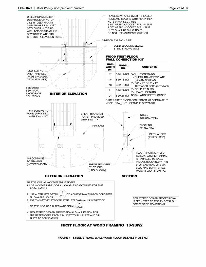
The tabulated in-plane shear values shown in Table 7 apply to SSW panels installed on wood floor framing in accordance with Figure 4.
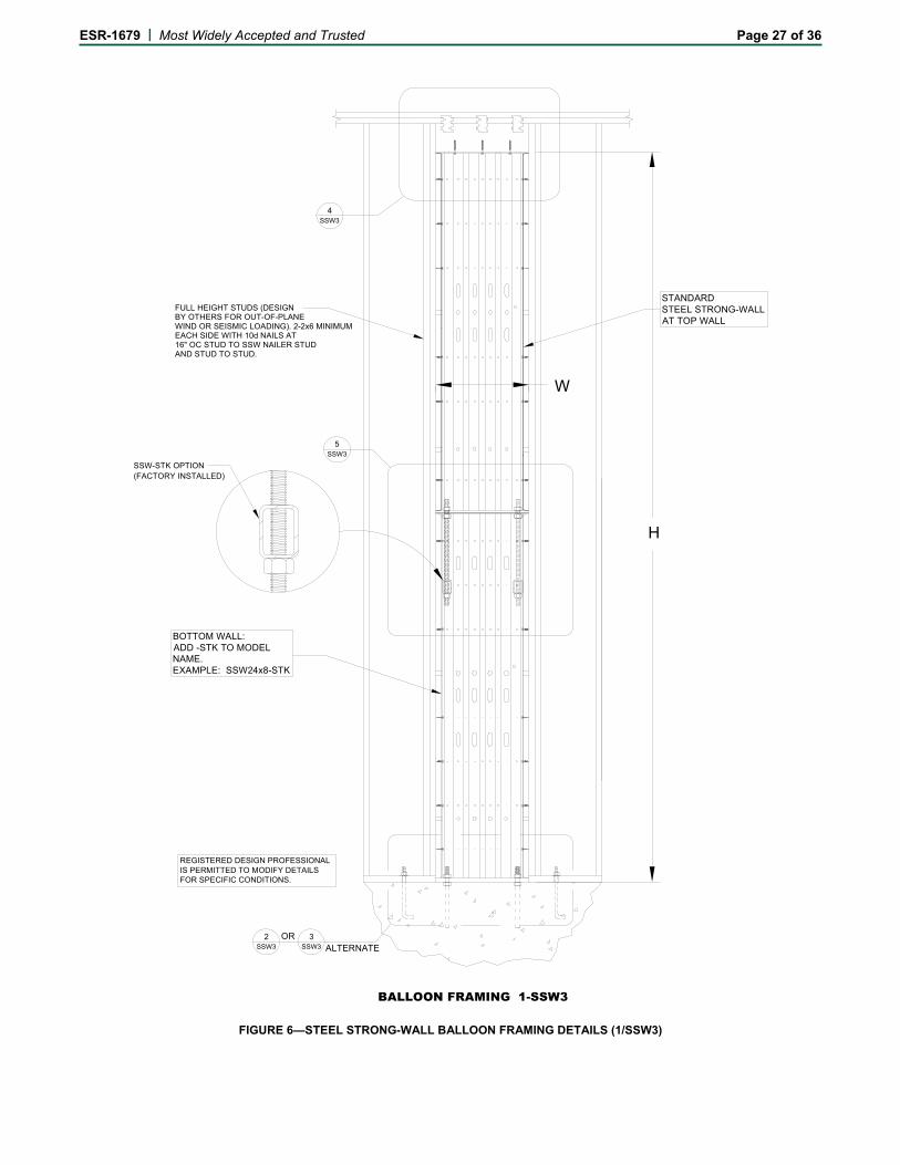
For SSW panels used in balloon framing with nominal overall heights from 15 feet to 20 feet (4572 mm to 6096 mm), the tabulated in-plane ASD shear values in Table 8 of this report apply to panels installed on concrete foundations in accordance with Figure 6. Full-height studs or posts on each side of the SSW panel must be designed
by the registered design professional to resist out-of-plane wind or earthquake effects.
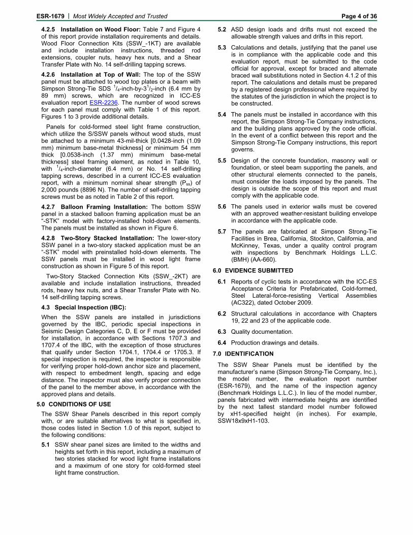
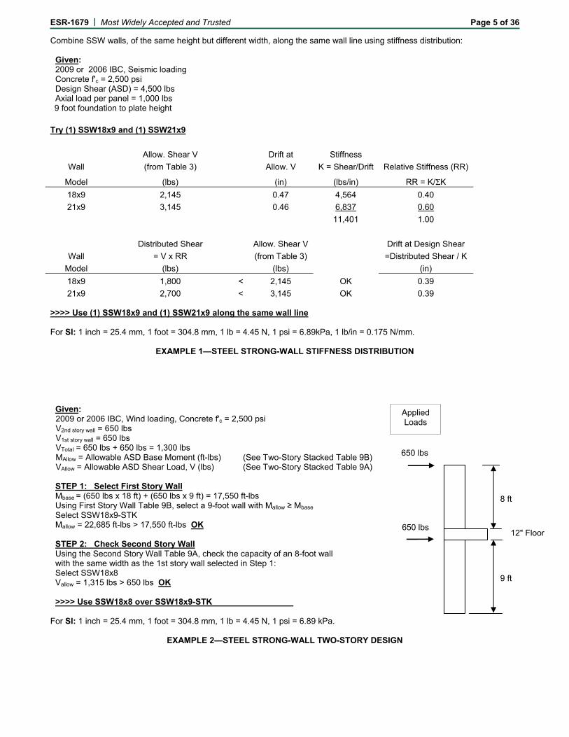
In-plane ASD shear values for two-story stacked SSW panel applications in wood light frame construction are set forth in Table 9 of this report. Two-story stacked applications must consider the effects of cumulative overturning. A sample calculation is represented in Example 2 following the text of this report. The tabulated allowable base moments in Table 9B of this report are for panels supported directly on normal weight concrete foundations with a minimum specified compressive strength of 2,500 psi (17.2 MPa).
Applied vertical gravity loads, when used in combination with the shear loads in Tables 3 and 7 to 10 of this report, must not exceed the corresponding allowable axial loads shown in the tables or stated in the table footnotes.
Allowable ASD in-plane shear values provided in Tables 3 and 7 to 10 are applicable to both ASD basic load combinations in IBC Section 1605.3.1 and the alternative basic load combinations in IBC Section 1605.3.2.
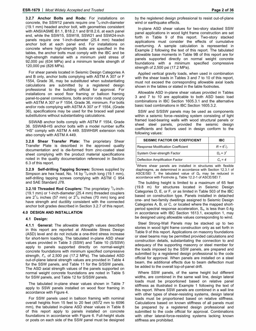
SSW and S/SSW panels may be used as components within a seismic force–resisting system consisting of light framed load-bearing walls with wood structural panels or sheet steel panels, provided the seismic design coefficients and factors used in design conform to the following values:
SEISMIC FACTOR OR COEFFICIENT IBC
Response Modification Coefficient R = 61/2
System Over-strength Factor Ωo = 31
Deflection Amplification Factor Cd = 4 1Where shear panels are installed in structures with flexible diaphragms, as determined in accordance with Section 12.3.1 of ASCE/SEI 7, the tabulated value of Ω0 may be reduced in accordance with Footnote g, Table 12.2-1 of ASCE/SEI 7.
The building height is limited to a maximum of 65 feet (19.8 m) for structures located in Seismic Design Categories D, E, or F, or as limited in Table 503 of the IBC based on construction type. Panels installed in detached one- and two-family dwellings assigned to Seismic Design Categories A, B, or C, or located where the mapped short-period spectral response acceleration, Ss, is less than 0.4g in accordance with IBC Section 1613.1, exception 1, may be designed using allowable values corresponding to wind.
Steel Strong-Wall Panels may be stacked up to two stories in wood light frame construction only as set forth in Table 9 of this report. Applications on masonry foundations or steel beams may be permitted provided calculations and construction details, substantiating the connection to and adequacy of the supporting masonry or steel member for the loads imposed by the SSW panels, are prepared and submitted by a registered design professional to the code official for approval. When panels are installed on a steel beam, the additional effects due to beam deflection must be added to the overall top-of-panel drift.
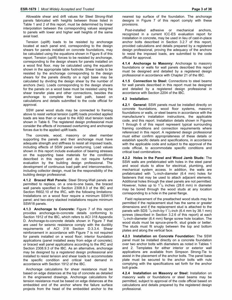
Where SSW panels, of the same height but different widths, are combined in the same wall line, design lateral loads must be proportioned based on relative panel stiffness as illustrated in Example 1 following the text of this report. Where SSW panels are combined in a wall line with other types of shear-resisting systems, design lateral loads must be proportioned based on relative stiffness. Calculations based on known stiffness of all panels must be prepared by a registered design professional and submitted to the code official for approval. Combinations with other lateral-force-resisting systems lacking known stiffness are prohibited.
ESR-1679 | Most Widely Accepted and Trusted Page 3 of 36
Allowable shear and drift values for Steel Strong-Wall panels fabricated with heights between those listed in Table 1 and 2 of this report, must be determined by linear interpolation between the corresponding values assigned to panels with lower and higher wall heights of the same axial load.
Tension (uplift) loads to be resisted by anchorage located at each panel end, corresponding to the design shears for panels installed on concrete foundations, may be calculated using the equations shown in Figure 8 of this report. Tension (uplift) forces to be resisted by anchorage, corresponding to the design shears for panels installed on a wood first floor, may be calculated using the equation shown in the appropriate table footnote. Shear loads to be resisted by the anchorage corresponding to the design shears for the panels directly on a rigid base may be calculated by dividing the design shear by the number of anchors (two). Loads corresponding to the design shears for the panels on a wood base must be resisted using the shear transfer plate and other connections, besides the anchorage to complete the load path, based on calculations and details submitted to the code official for approval.
SSW panel wood studs may be connected to framing above to resist vertical tension (uplift) loads provided applied loads are less than or equal to the ASD stud tension loads shown in Table 6. The registered design professional must consider the effects of increased overturning and anchorage forces due to the applied uplift loads.
The concrete, wood, masonry or steel member supporting the panels and their anchorage must have adequate strength and stiffness to resist all imposed loads, including effects of SSW panel overturning. Load values shown in this report include evaluation of bearing stresses on the supporting base materials for the conditions described in this report and do not require further evaluation by the building design professional. The development of continuous load path and interconnection, including collector design, must be the responsibility of the building design professional.
4.1.2 Braced Wall Panels: Steel Strong-Wall panels are permitted to replace, on a one-to-one basis, the braced wall panels specified in Section 2308.9.3 of the IBC and Section R602.10 of the IRC, with the following limitations: Installations on a wood floor require a minimum SSW15 panel; and two-story stacked installations require minimum SSW18 panels.
4.1.3 Anchorage to Concrete: Figure 7 of this report provides anchorage-to-concrete details conforming to Section 1912 of the IBC, which refers to ACI 318 Appendix D. Anchorage-to-concrete details shown in Figure 7 that are used for seismic resistance comply with the ductility requirements of ACI 318 Section D.3.3.4. Shear reinforcement in accordance with Figure 7 is not required for panels installed on a wood floor; interior foundation applications (panel installed away from edge of concrete); or braced wall panel applications according to the IRC and Section 2308.9.3 of the IBC. As an alternative, anchorage may be designed by a registered design professional and installed to resist tension and shear loads to accommodate the specific condition and critical load demand in accordance with Section 1912 of the IBC.
Anchorage calculations for shear resistance must be based on edge distances at the top of concrete as detailed in the engineered drawings. Anchorage calculations for tension resistance must be based on edge distances at the embedded end of the anchor where the failure surface projects from the head of the embedded anchor to the
nearest top surface of the foundation. The anchorage designs in Figure 7 of this report comply with these provisions.
Post-installed adhesive or mechanical anchors, recognized in a current ICC-ES evaluation report for installation in concrete, may be used in lieu of cast-in-place anchor bolts described in Section 3.2.7 of this report, provided calculations and details prepared by a registered design professional, proving the adequacy of the anchors to resist the imposed loads, are submitted to the code official for approval.
4.1.4 Anchorage to Masonry: Anchorage to masonry foundations or walls for wall panels described this report must be designed and detailed by a registered design professional in accordance with Chapter 21 of the IBC.
4.1.5 Connection to Steel: Connections to steel beams for wall panels described in this report must be designed and detailed by a registered design professional in accordance with Section 2204 of the IBC.
4.2 Installation:
4.2.1 General: SSW panels must be installed directly on concrete foundations, wood floor systems, masonry foundations or walls, or steel beams in accordance with the manufacturer’s installation instructions, the applicable code, and this report. Installation details shown in Figures 1 through 6 of this report represent typical surrounding framing conditions and connection requirements where referenced in this report. A registered design professional must either confirm appropriateness of these details or establish specific details and specifications, in accordance with the applicable code and subject to the approval of the code official, to accommodate specific conditions and critical load combinations.
4.2.2 Holes in the Panel and Wood Jamb Studs: The SSW walls are prefabricated with holes in the steel panel and wood studs to allow for electrical, plumbing, and mechanical system access. In addition, the walls are prefabricated with 1/4-inch-diameter (6.4 mm) holes for fasteners that may be used to attach adjacent elements. Additional holes through the steel panels are not permitted. However, holes up to 11/8 inches (28.6 mm) in diameter may be bored through the wood studs at any location corresponding to a hole in the panel flange.
Field replacement of the preattached wood studs may be permitted if the replacement stud has the same or greater dimensions and if the replacement stud is attached to the panels with SDS 1/4-inch-by-11/2-inch (6.4 mm by 38.1 mm) screws (described in Section 3.2.6 of this report) at each 1/4-inch-diameter (6.4 mm) flange screw hole location. The wood studs must be spruce-pine-fir, stud grade or better. The studs must fit snugly between the top and bottom plates and along the vertical face.
4.2.3 Installation on Concrete Foundation: The SSW panel must be installed directly on a concrete foundation over two anchor bolts with diameters as noted in Tables 1 and 2. Templates for either interior or exterior wall applications are available from Simpson Strong-Tie to assist in the placement of the anchor bolts. The panel base plate must be secured to the anchor bolts with nuts complying with the specifications set forth for the anchor bolt grade.
4.2.4 Installation on Masonry or Steel: Installation on masonry walls or foundations or steel beams may be permitted, subject to approval of the code official based on calculations and details prepared by the registered design professional.
ESR-1679 | Most Widely Accepted and Trusted Page 4 of 36
4.2.5 Installation on Wood Floor: Table 7 and Figure 4 of this report provide installation requirements and details. Wood Floor Connection Kits (SSW_-1KT) are available and include installation instructions, threaded rod extensions, coupler nuts, heavy hex nuts, and a Shear Transfer Plate with No. 14 self-drilling tapping screws.
4.2.6 Installation at Top of Wall: The top of the SSW panel must be attached to wood top plates or a beam with Simpson Strong-Tie SDS 1/4-inch-by-31/2-inch (6.4 mm by 89 mm) screws, which are recognized in ICC-ES evaluation report ESR-2236. The number of wood screws for each panel must comply with Table 1 of this report. Figures 1 to 3 provide additional details.
Panels for cold-formed steel light frame construction, which utilize the S/SSW panels without wood studs, must be attached to a minimum 43-mil-thick [0.0428-inch (1.09 mm) minimum base-metal thickness] or minimum 54 mm thick [0.0538-inch (1.37 mm) minimum base-metal thickness] steel framing element, as noted in Table 10, with 1/4-inch-diameter (6.4 mm) or No. 14 self-drilling tapping screws, described in a current ICC-ES evaluation report, with a minimum nominal shear strength (Pss) of 2,000 pounds (8896 N). The number of self-drilling tapping screws must be as noted in Table 2 of this report.
4.2.7 Balloon Framing Installation: The bottom SSW panel in a stacked balloon framing application must be an “-STK” model with factory-installed hold-down elements. The panels must be installed as shown in Figure 6.
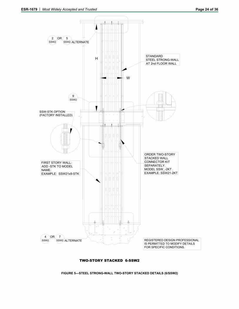
4.2.8 Two-Story Stacked Installation: The lower-story SSW panel in a two-story stacked application must be an “-STK” model with preinstalled hold-down elements. The SSW panels must be installed in wood light frame construction as shown in Figure 5 of this report.
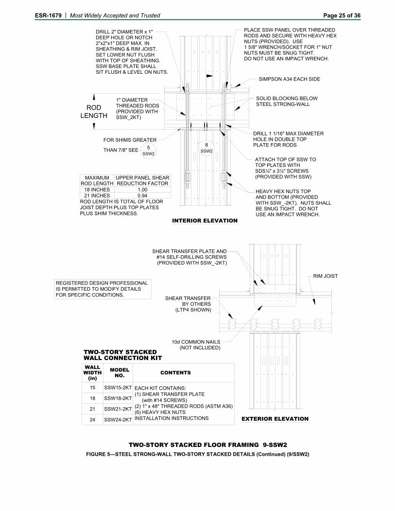
Two-Story Stacked Connection Kits (SSW_-2KT) are available and include installation instructions, threaded rods, heavy hex nuts, and a Shear Transfer Plate with No. 14 self-drilling tapping screws.
4.3 Special Inspection (IBC):
When the SSW panels are installed in jurisdictions governed by the IBC, periodic special inspections in Seismic Design Categories C, D, E or F must be provided for installation, in accordance with Sections 1707.3 and 1707.4 of the IBC, with the exception of those structures that qualify under Section 1704.1, 1704.4 or 1705.3. If special inspection is required, the inspector is responsible for verifying proper hold-down anchor size and placement, with respect to embedment length, spacing and edge distance. The inspector must also verify proper connection of the panel to the member above, in accordance with the approved plans and details.
5.0 CONDITIONS OF USE
The SSW Shear Panels described in this report comply with, or are suitable alternatives to what is specified in, those codes listed in Section 1.0 of this report, subject to the following conditions:
5.1 SSW shear panel sizes are limited to the widths and heights set forth in this report, including a maximum of two stories stacked for wood light frame installations and a maximum of one story for cold-formed steel light frame construction.
5.2 ASD design loads and drifts must not exceed the allowable strength values and drifts in this report.
5.3 Calculations and details, justifying that the panel use is in compliance with the applicable code and this evaluation report, must be submitted to the code official for approval, except for braced and alternate braced wall substitutions noted in Section 4.1.2 of this report. The calculations and details must be prepared by a registered design professional where required by the statutes of the jurisdiction in which the project is to be constructed.
5.4 The panels must be installed in accordance with this report, the Simpson Strong-Tie Company instructions, and the building plans approved by the code official. In the event of a conflict between this report and the Simpson Strong-Tie Company instructions, this report governs.
5.5 Design of the concrete foundation, masonry wall or foundation, or steel beam supporting the panels, and other structural elements connected to the panels, must consider the loads imposed by the panels. The design is outside the scope of this report and must comply with the applicable code.
5.6 The panels used in exterior walls must be covered with an approved weather-resistant building envelope in accordance with the applicable code.
5.7 The panels are fabricated at Simpson Strong-Tie Facilities in Brea, California, Stockton, California, and McKinney, Texas, under a quality control program with inspections by Benchmark Holdings L.L.C. (BMH) (AA-660).
6.0 EVIDENCE SUBMITTED
6.1 Reports of cyclic tests in accordance with the ICC-ES Acceptance Criteria for Prefabricated, Cold-formed, Steel Lateral-force-resisting Vertical Assemblies (AC322), dated October 2009.
6.2 Structural calculations in accordance with Chapters 19, 22 and 23 of the applicable code.
6.3 Quality documentation.
6.4 Production drawings and details.
7.0 IDENTIFICATION
The SSW Shear Panels must be identified by the manufacturer’s name (Simpson Strong-Tie Company, Inc.), the model number, the evaluation report number (ESR-1679), and the name of the inspection agency (Benchmark Holdings L.L.C.). In lieu of the model number, panels fabricated with intermediate heights are identified by the next tallest standard model number followed by xH1-specified height (in inches). For example, SSW18x9xH1-103.
ESR-1679 | Most Widely Accepted and Trusted Page 5 of 36 Combine SSW walls, of the same height but different width, along the same wall line using stiffness distribution:
Given: 2009 or 2006 IBC, Seismic loading Concrete f'c = 2,500 psi Design Shear (ASD) = 4,500 lbs Axial load per panel = 1,000 lbs 9 foot foundation to plate height
Try (1) SSW18x9 and (1) SSW21x9
Allow. Shear V Drift at Stiffness
Wall (from Table 3) Allow. V K = Shear/Drift Relative Stiffness (RR)
Model (lbs) (in) (lbs/in) RR = K/ΣK
18x9 2,145 0.47 4,564 0.40
21x9 3,145 0.46 6,837 0.60
11,401 1.00
Distributed Shear Allow. Shear V Drift at Design Shear
Wall = V x RR (from Table 3) =Distributed Shear / K
Model (lbs) (lbs) (in)
18x9 1,800 < 2,145 OK 0.39
21x9 2,700 < 3,145 OK 0.39 >>>> Use (1) SSW18x9 and (1) SSW21x9 along the same wall line For SI: 1 inch = 25.4 mm, 1 foot = 304.8 mm, 1 lb = 4.45 N, 1 psi = 6.89kPa, 1 lb/in = 0.175 N/mm.
EXAMPLE 1—STEEL STRONG-WALL STIFFNESS DISTRIBUTION
Given: 2009 or 2006 IBC, Wind loading, Concrete f'c = 2,500 psi V2nd story wall = 650 lbs V1st story wall = 650 lbs VTotal = 650 lbs + 650 lbs = 1,300 lbs MAllow = Allowable ASD Base Moment (ft-lbs) (See Two-Story Stacked Table 9B) VAllow = Allowable ASD Shear Load, V (lbs) (See Two-Story Stacked Table 9A) STEP 1: Select First Story Wall Mbase = (650 lbs x 18 ft) + (650 lbs x 9 ft) = 17,550 ft-lbs Using First Story Wall Table 9B, select a 9-foot wall with Mallow ≥ Mbase Select SSW18x9-STK Mallow = 22,685 ft-lbs > 17,550 ft-lbs OK STEP 2: Check Second Story Wall Using the Second Story Wall Table 9A, check the capacity of an 8-foot wall with the same width as the 1st story wall selected in Step 1: Select SSW18x8 Vallow = 1,315 lbs > 650 lbs OK >>>> Use SSW18x8 over SSW18x9-STK
For SI: 1 inch = 25.4 mm, 1 foot = 304.8 mm, 1 lb = 4.45 N, 1 psi = 6.89 kPa.
EXAMPLE 2—STEEL STRONG-WALL TWO-STORY DESIGN
12" Floor
650 lbs
650 lbs
Applied Loads
8 ft
9 ft
ESR-1679 | Most Widely Accepted and Trusted Page 6 of 36
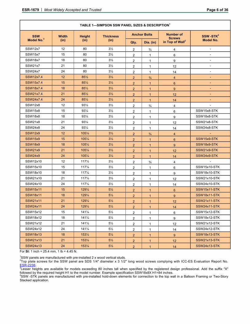
TABLE 1—SIMPSON SSW PANEL SIZES & DESCRIPTION1
SSW Model No.3
Width (in)
Height (in)
Thickness (in)
Anchor Bolts Number of Screws
in Top of Wall2
SSW -STK4 Model No.
Qty. Dia. (in)
SSW12x7 12 80 3½ 2 ¾ 4 -
SSW15x7 15 80 3½ 2 1 6 -
SSW18x7 18 80 3½ 2 1 9 -
SSW21x7 21 80 3½ 2 1 12 -
SSW24x7 24 80 3½ 2 1 14 -
SSW12x7.4 12 85½ 3½ 2 ¾ 4 -
SSW15x7.4 15 85½ 3½ 2 1 6 -
SSW18x7.4 18 85½ 3½ 2 1 9 -
SSW21x7.4 21 85½ 3½ 2 1 12 -
SSW24x7.4 24 85½ 3½ 2 1 14 -
SSW12x8 12 93¼ 3½ 2 ¾ 4 -
SSW15x8 15 93¼ 3½ 2 1 6 SSW15x8-STK
SSW18x8 18 93¼ 3½ 2 1 9 SSW18x8-STK
SSW21x8 21 93¼ 3½ 2 1 12 SSW21x8-STK
SSW24x8 24 93¼ 3½ 2 1 14 SSW24x8-STK
SSW12x9 12 105¼ 3½ 2 ¾ 4 -
SSW15x9 15 105¼ 3½ 2 1 6 SSW15x9-STK
SSW18x9 18 105¼ 3½ 2 1 9 SSW18x9-STK
SSW21x9 21 105¼ 3½ 2 1 12 SSW21x9-STK
SSW24x9 24 105¼ 3½ 2 1 14 SSW24x9-STK
SSW12x10 12 117¼ 3½ 2 ¾ 4 -
SSW15x10 15 117¼ 3½ 2 1 6 SSW15x10-STK
SSW18x10 18 117¼ 3½ 2 1 9 SSW18x10-STK
SSW21x10 21 117¼ 3½ 2 1 12 SSW21x10-STK
SSW24x10 24 117¼ 3½ 2 1 14 SSW24x10-STK
SSW15x11 15 129¼ 5½ 2 1 6 SSW15x11-STK
SSW18x11 18 129¼ 5½ 2 1 9 SSW18x11-STK
SSW21x11 21 129¼ 5½ 2 1 12 SSW21x11-STK
SSW24x11 24 129¼ 5½ 2 1 14 SSW24x11-STK
SSW15x12 15 141¼ 5½ 2 1 6 SSW15x12-STK
SSW18x12 18 141¼ 5½ 2 1 9 SSW18x12-STK
SSW21x12 21 141¼ 5½ 2 1 12 SSW21x12-STK
SSW24x12 24 141¼ 5½ 2 1 14 SSW24x12-STK
SSW18x13 18 153¼ 5½ 2 1 9 SSW18x13-STK
SSW21x13 21 153¼ 5½ 2 1 12 SSW21x13-STK
SSW24x13 24 153¼ 5½ 2 1 14 SSW24x13-STK
For SI: 1 inch = 25.4 mm, 1 lb = 4.45 N.
1SSW panels are manufactured with pre-installed 2 x wood vertical studs. 2Top plate screws for the SSW panel are SDS 1/4" diameter x 3 1/2" long wood screws complying with ICC-ES Evaluation Report No. ESR-2236. 3Lesser heights are available for models exceeding 80 inches tall when specified by the registered design professional. Add the suffix "X" followed by the required height H1 to the model number. Example specification SSW18x8X H1=84 inches. 4SSW -STK panels are manufactured with pre-installed hold-down elements for connection to the top wall in a Balloon Framing or Two-Story Stacked application.
ESR-1679 | Most Widely Accepted and Trusted Page 7 of 36
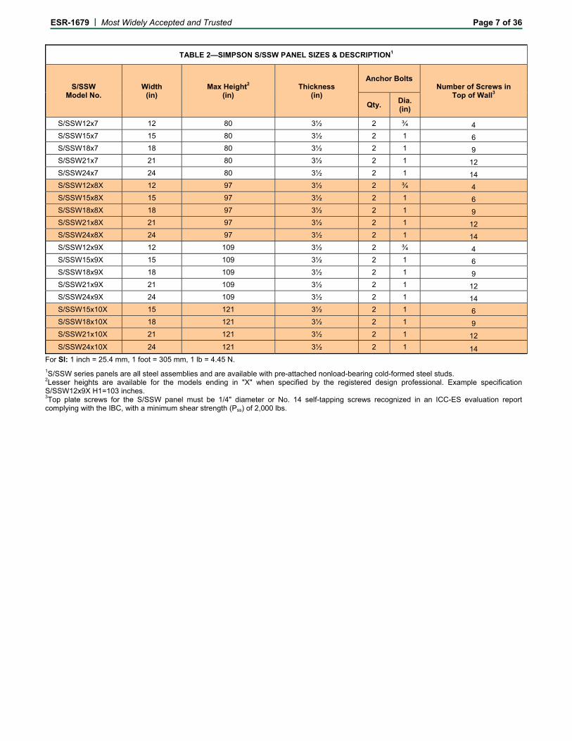
TABLE 2—SIMPSON S/SSW PANEL SIZES & DESCRIPTION1
S/SSW Model No.
Width (in)
Max Height2 (in)
Thickness (in)
Anchor Bolts Number of Screws in
Top of Wall3 Qty.
Dia. (in)
S/SSW12x7 12 80 3½ 2 ¾ 4
S/SSW15x7 15 80 3½ 2 1 6
S/SSW18x7 18 80 3½ 2 1 9
S/SSW21x7 21 80 3½ 2 1 12
S/SSW24x7 24 80 3½ 2 1 14
S/SSW12x8X 12 97 3½ 2 ¾ 4
S/SSW15x8X 15 97 3½ 2 1 6
S/SSW18x8X 18 97 3½ 2 1 9
S/SSW21x8X 21 97 3½ 2 1 12
S/SSW24x8X 24 97 3½ 2 1 14
S/SSW12x9X 12 109 3½ 2 ¾ 4
S/SSW15x9X 15 109 3½ 2 1 6
S/SSW18x9X 18 109 3½ 2 1 9
S/SSW21x9X 21 109 3½ 2 1 12
S/SSW24x9X 24 109 3½ 2 1 14
S/SSW15x10X 15 121 3½ 2 1 6
S/SSW18x10X 18 121 3½ 2 1 9
S/SSW21x10X 21 121 3½ 2 1 12
S/SSW24x10X 24 121 3½ 2 1 14
For SI: 1 inch = 25.4 mm, 1 foot = 305 mm, 1 lb = 4.45 N.
1S/SSW series panels are all steel assemblies and are available with pre-attached nonload-bearing cold-formed steel studs. 2Lesser heights are available for the models ending in "X" when specified by the registered design professional. Example specification S/SSW12x9X H1=103 inches. 3Top plate screws for the S/SSW panel must be 1/4" diameter or No. 14 self-tapping screws recognized in an ICC-ES evaluation report complying with the IBC, with a minimum shear strength (Pss) of 2,000 lbs.
ESR-1679 | Most Widely Accepted and Trusted Page 8 of 36
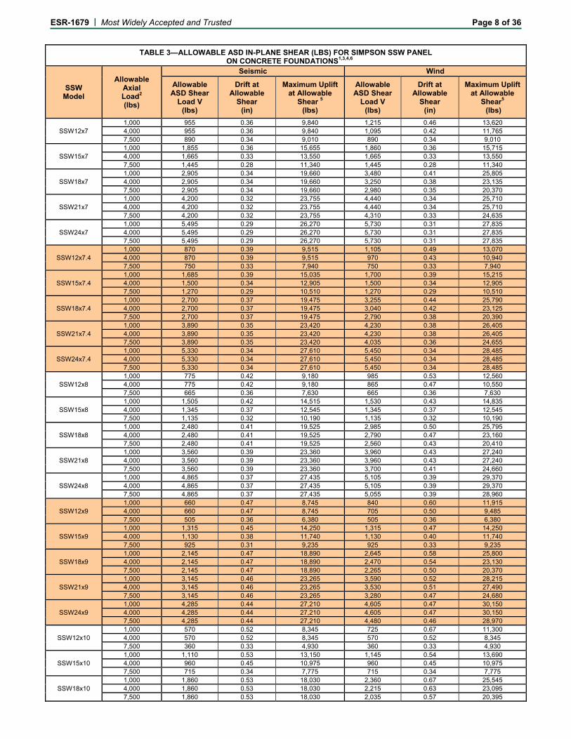
TABLE 3—ALLOWABLE ASD IN-PLANE SHEAR (LBS) FOR SIMPSON SSW PANEL ON CONCRETE FOUNDATIONS1,3,4,6
SSW Model
Allowable Axial Load2 (lbs)
Seismic Wind
Allowable ASD Shear
Load V (lbs)
Drift at Allowable
Shear (in)
Maximum Uplift at Allowable
Shear 5 (lbs)
Allowable ASD Shear
Load V (lbs)
Drift at Allowable
Shear (in)
Maximum Uplift at Allowable
Shear5 (lbs)
SSW12x7 1,000 955 0.36 9,840 1,215 0.46 13,620 4,000 955 0.36 9,840 1,095 0.42 11,765 7,500 890 0.34 9,010 890 0.34 9,010
SSW15x7 1,000 1,855 0.36 15,655 1,860 0.36 15,715 4,000 1,665 0.33 13,550 1,665 0.33 13,550 7,500 1,445 0.28 11,340 1,445 0.28 11,340
SSW18x7 1,000 2,905 0.34 19,660 3,480 0.41 25,805 4,000 2,905 0.34 19,660 3,250 0.38 23,135 7,500 2,905 0.34 19,660 2,980 0.35 20,370
SSW21x7 1,000 4,200 0.32 23,755 4,440 0.34 25,710 4,000 4,200 0.32 23,755 4,440 0.34 25,710 7,500 4,200 0.32 23,755 4,310 0.33 24,635
SSW24x7 1,000 5,495 0.29 26,270 5,730 0.31 27,835 4,000 5,495 0.29 26,270 5,730 0.31 27,835 7,500 5,495 0.29 26,270 5,730 0.31 27,835
SSW12x7.4 1,000 870 0.39 9,515 1,105 0.49 13,070 4,000 870 0.39 9,515 970 0.43 10,940 7,500 750 0.33 7,940 750 0.33 7,940
SSW15x7.4 1,000 1,685 0.39 15,035 1,700 0.39 15,215 4,000 1,500 0.34 12,905 1,500 0.34 12,905 7,500 1,270 0.29 10,510 1,270 0.29 10,510
SSW18x7.4 1,000 2,700 0.37 19,475 3,255 0.44 25,790 4,000 2,700 0.37 19,475 3,040 0.42 23,125 7,500 2,700 0.37 19,475 2,790 0.38 20,390
SSW21x7.4 1,000 3,890 0.35 23,420 4,230 0.38 26,405 4,000 3,890 0.35 23,420 4,230 0.38 26,405 7,500 3,890 0.35 23,420 4,035 0.36 24,655
SSW24x7.4 1,000 5,330 0.34 27,610 5,450 0.34 28,485 4,000 5,330 0.34 27,610 5,450 0.34 28,485 7,500 5,330 0.34 27,610 5,450 0.34 28,485
SSW12x8 1,000 775 0.42 9,180 985 0.53 12,560 4,000 775 0.42 9,180 865 0.47 10,550 7,500 665 0.36 7,630 665 0.36 7,630
SSW15x8 1,000 1,505 0.42 14,515 1,530 0.43 14,835 4,000 1,345 0.37 12,545 1,345 0.37 12,545 7,500 1,135 0.32 10,190 1,135 0.32 10,190
SSW18x8 1,000 2,480 0.41 19,525 2,985 0.50 25,795 4,000 2,480 0.41 19,525 2,790 0.47 23,160 7,500 2,480 0.41 19,525 2,560 0.43 20,410
SSW21x8 1,000 3,560 0.39 23,360 3,960 0.43 27,240 4,000 3,560 0.39 23,360 3,960 0.43 27,240 7,500 3,560 0.39 23,360 3,700 0.41 24,660
SSW24x8 1,000 4,865 0.37 27,435 5,105 0.39 29,370 4,000 4,865 0.37 27,435 5,105 0.39 29,370 7,500 4,865 0.37 27,435 5,055 0.39 28,960
SSW12x9 1,000 660 0.47 8,745 840 0.60 11,915 4,000 660 0.47 8,745 705 0.50 9,485 7,500 505 0.36 6,380 505 0.36 6,380
SSW15x9 1,000 1,315 0.45 14,250 1,315 0.47 14,250 4,000 1,130 0.38 11,740 1,130 0.40 11,740 7,500 925 0.31 9,235 925 0.33 9,235
SSW18x9 1,000 2,145 0.47 18,890 2,645 0.58 25,800 4,000 2,145 0.47 18,890 2,470 0.54 23,130 7,500 2,145 0.47 18,890 2,265 0.50 20,370
SSW21x9 1,000 3,145 0.46 23,265 3,590 0.52 28,215 4,000 3,145 0.46 23,265 3,530 0.51 27,490 7,500 3,145 0.46 23,265 3,280 0.47 24,680
SSW24x9 1,000 4,285 0.44 27,210 4,605 0.47 30,150 4,000 4,285 0.44 27,210 4,605 0.47 30,150 7,500 4,285 0.44 27,210 4,480 0.46 28,970
SSW12x10 1,000 570 0.52 8,345 725 0.67 11,300 4,000 570 0.52 8,345 570 0.52 8,345 7,500 360 0.33 4,930 360 0.33 4,930
SSW15x10 1,000 1,110 0.53 13,150 1,145 0.54 13,690 4,000 960 0.45 10,975 960 0.45 10,975 7,500 715 0.34 7,775 715 0.34 7,775
SSW18x10 1,000 1,860 0.53 18,030 2,360 0.67 25,545 4,000 1,860 0.53 18,030 2,215 0.63 23,095 7,500 1,860 0.53 18,030 2,035 0.57 20,395
ESR-1679 | Most Widely Accepted and Trusted Page 9 of 36
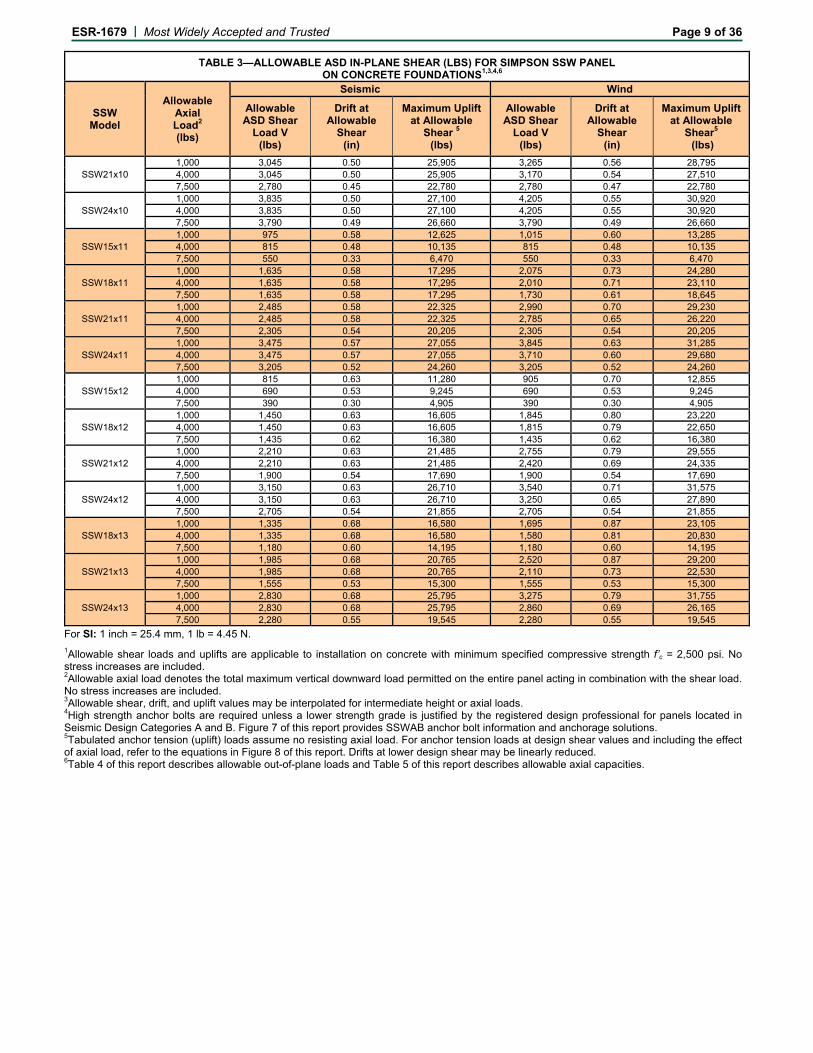
TABLE 3—ALLOWABLE ASD IN-PLANE SHEAR (LBS) FOR SIMPSON SSW PANEL ON CONCRETE FOUNDATIONS1,3,4,6
SSW Model
Allowable Axial Load2 (lbs)
Seismic Wind
Allowable ASD Shear
Load V (lbs)
Drift at Allowable
Shear (in)
Maximum Uplift at Allowable
Shear 5 (lbs)
Allowable ASD Shear
Load V (lbs)
Drift at Allowable
Shear (in)
Maximum Uplift at Allowable
Shear5 (lbs)
SSW21x10 1,000 3,045 0.50 25,905 3,265 0.56 28,795 4,000 3,045 0.50 25,905 3,170 0.54 27,510 7,500 2,780 0.45 22,780 2,780 0.47 22,780
SSW24x10 1,000 3,835 0.50 27,100 4,205 0.55 30,920 4,000 3,835 0.50 27,100 4,205 0.55 30,920 7,500 3,790 0.49 26,660 3,790 0.49 26,660
SSW15x11 1,000 975 0.58 12,625 1,015 0.60 13,285 4,000 815 0.48 10,135 815 0.48 10,135 7,500 550 0.33 6,470 550 0.33 6,470
SSW18x11 1,000 1,635 0.58 17,295 2,075 0.73 24,280 4,000 1,635 0.58 17,295 2,010 0.71 23,110 7,500 1,635 0.58 17,295 1,730 0.61 18,645
SSW21x11 1,000 2,485 0.58 22,325 2,990 0.70 29,230 4,000 2,485 0.58 22,325 2,785 0.65 26,220 7,500 2,305 0.54 20,205 2,305 0.54 20,205
SSW24x11 1,000 3,475 0.57 27,055 3,845 0.63 31,285 4,000 3,475 0.57 27,055 3,710 0.60 29,680 7,500 3,205 0.52 24,260 3,205 0.52 24,260
SSW15x12 1,000 815 0.63 11,280 905 0.70 12,855 4,000 690 0.53 9,245 690 0.53 9,245 7,500 390 0.30 4,905 390 0.30 4,905
SSW18x12 1,000 1,450 0.63 16,605 1,845 0.80 23,220 4,000 1,450 0.63 16,605 1,815 0.79 22,650 7,500 1,435 0.62 16,380 1,435 0.62 16,380
SSW21x12 1,000 2,210 0.63 21,485 2,755 0.79 29,555 4,000 2,210 0.63 21,485 2,420 0.69 24,335 7,500 1,900 0.54 17,690 1,900 0.54 17,690
SSW24x12 1,000 3,150 0.63 26,710 3,540 0.71 31,575 4,000 3,150 0.63 26,710 3,250 0.65 27,890 7,500 2,705 0.54 21,855 2,705 0.54 21,855
SSW18x13 1,000 1,335 0.68 16,580 1,695 0.87 23,105 4,000 1,335 0.68 16,580 1,580 0.81 20,830 7,500 1,180 0.60 14,195 1,180 0.60 14,195
SSW21x13 1,000 1,985 0.68 20,765 2,520 0.87 29,200 4,000 1,985 0.68 20,765 2,110 0.73 22,530 7,500 1,555 0.53 15,300 1,555 0.53 15,300
SSW24x13 1,000 2,830 0.68 25,795 3,275 0.79 31,755 4,000 2,830 0.68 25,795 2,860 0.69 26,165 7,500 2,280 0.55 19,545 2,280 0.55 19,545
For SI: 1 inch = 25.4 mm, 1 lb = 4.45 N.
1Allowable shear loads and uplifts are applicable to installation on concrete with minimum specified compressive strength f’c = 2,500 psi. No stress increases are included. 2Allowable axial load denotes the total maximum vertical downward load permitted on the entire panel acting in combination with the shear load. No stress increases are included. 3Allowable shear, drift, and uplift values may be interpolated for intermediate height or axial loads. 4High strength anchor bolts are required unless a lower strength grade is justified by the registered design professional for panels located in Seismic Design Categories A and B. Figure 7 of this report provides SSWAB anchor bolt information and anchorage solutions. 5Tabulated anchor tension (uplift) loads assume no resisting axial load. For anchor tension loads at design shear values and including the effect of axial load, refer to the equations in Figure 8 of this report. Drifts at lower design shear may be linearly reduced. 6Table 4 of this report describes allowable out-of-plane loads and Table 5 of this report describes allowable axial capacities.
ESR-1679 | Most Widely Accepted and Trusted Page 10 of 36
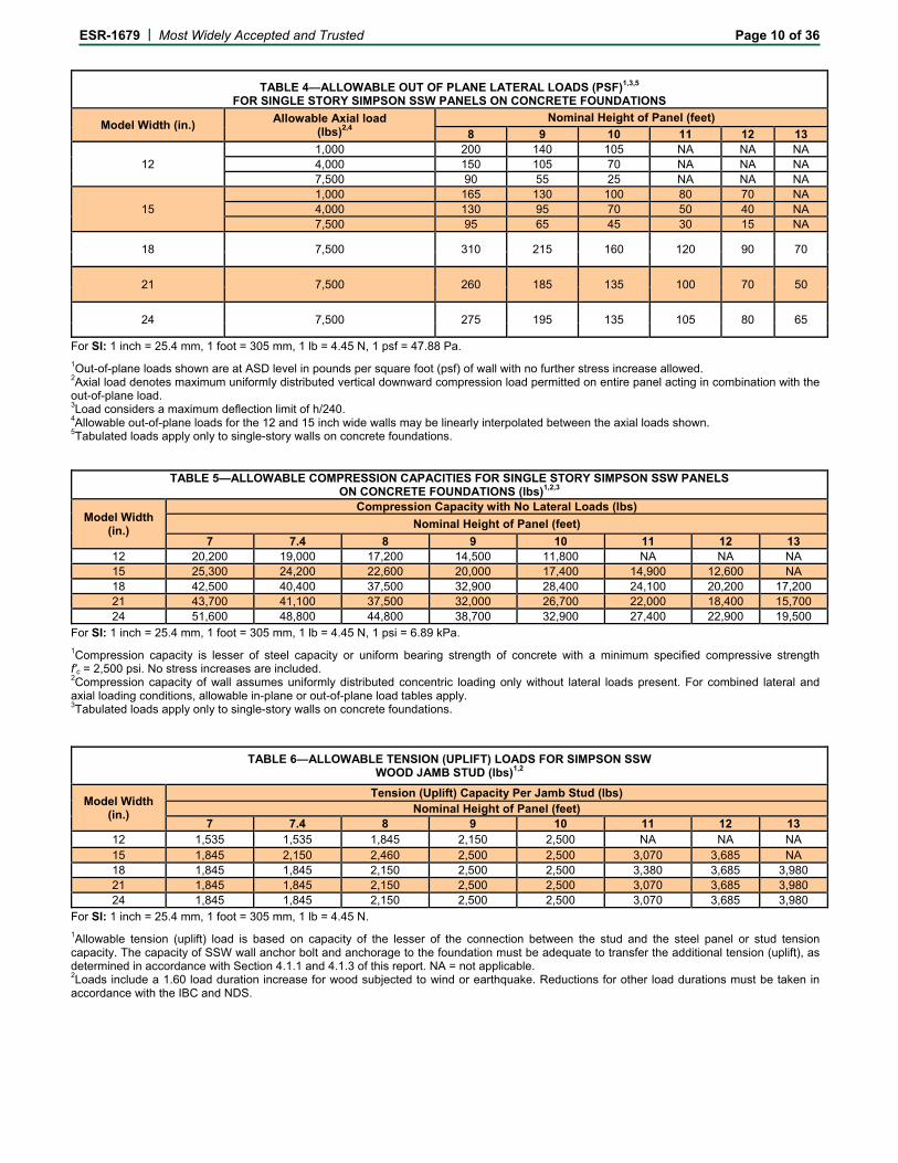
TABLE 4—ALLOWABLE OUT OF PLANE LATERAL LOADS (PSF)1,3,5 FOR SINGLE STORY SIMPSON SSW PANELS ON CONCRETE FOUNDATIONS
Model Width (in.) Allowable Axial load
(lbs)2,4 Nominal Height of Panel (feet)
8 9 10 11 12 13
12 1,000 200 140 105 NA NA NA 4,000 150 105 70 NA NA NA 7,500 90 55 25 NA NA NA
15 1,000 165 130 100 80 70 NA 4,000 130 95 70 50 40 NA 7,500 95 65 45 30 15 NA
18 7,500 310 215 160 120 90 70
21 7,500 260 185 135 100 70 50
24 7,500 275 195 135 105 80 65
For SI: 1 inch = 25.4 mm, 1 foot = 305 mm, 1 lb = 4.45 N, 1 psf = 47.88 Pa.
1Out-of-plane loads shown are at ASD level in pounds per square foot (psf) of wall with no further stress increase allowed. 2Axial load denotes maximum uniformly distributed vertical downward compression load permitted on entire panel acting in combination with the out-of-plane load. 3Load considers a maximum deflection limit of h/240. 4Allowable out-of-plane loads for the 12 and 15 inch wide walls may be linearly interpolated between the axial loads shown. 5Tabulated loads apply only to single-story walls on concrete foundations.
TABLE 5—ALLOWABLE COMPRESSION CAPACITIES FOR SINGLE STORY SIMPSON SSW PANELS ON CONCRETE FOUNDATIONS (lbs)1,2,3
Model Width (in.)
Compression Capacity with No Lateral Loads (lbs)
Nominal Height of Panel (feet)
7 7.4 8 9 10 11 12 13 12 20,200 19,000 17,200 14,500 11,800 NA NA NA 15 25,300 24,200 22,600 20,000 17,400 14,900 12,600 NA 18 42,500 40,400 37,500 32,900 28,400 24,100 20,200 17,200 21 43,700 41,100 37,500 32,000 26,700 22,000 18,400 15,700 24 51,600 48,800 44,800 38,700 32,900 27,400 22,900 19,500
For SI: 1 inch = 25.4 mm, 1 foot = 305 mm, 1 lb = 4.45 N, 1 psi = 6.89 kPa.
1Compression capacity is lesser of steel capacity or uniform bearing strength of concrete with a minimum specified compressive strength f'c = 2,500 psi. No stress increases are included. 2Compression capacity of wall assumes uniformly distributed concentric loading only without lateral loads present. For combined lateral and axial loading conditions, allowable in-plane or out-of-plane load tables apply. 3Tabulated loads apply only to single-story walls on concrete foundations.
TABLE 6—ALLOWABLE TENSION (UPLIFT) LOADS FOR SIMPSON SSW WOOD JAMB STUD (lbs)1,2
Model Width (in.)
Tension (Uplift) Capacity Per Jamb Stud (lbs) Nominal Height of Panel (feet)
7 7.4 8 9 10 11 12 13 12 1,535 1,535 1,845 2,150 2,500 NA NA NA 15 1,845 2,150 2,460 2,500 2,500 3,070 3,685 NA 18 1,845 1,845 2,150 2,500 2,500 3,380 3,685 3,980 21 1,845 1,845 2,150 2,500 2,500 3,070 3,685 3,980 24 1,845 1,845 2,150 2,500 2,500 3,070 3,685 3,980
For SI: 1 inch = 25.4 mm, 1 foot = 305 mm, 1 lb = 4.45 N.
1Allowable tension (uplift) load is based on capacity of the lesser of the connection between the stud and the steel panel or stud tension capacity. The capacity of SSW wall anchor bolt and anchorage to the foundation must be adequate to transfer the additional tension (uplift), as determined in accordance with Section 4.1.1 and 4.1.3 of this report. NA = not applicable. 2Loads include a 1.60 load duration increase for wood subjected to wind or earthquake. Reductions for other load durations must be taken in accordance with the IBC and NDS.
ESR-1679 | Most Widely Accepted and Trusted Page 11 of 36
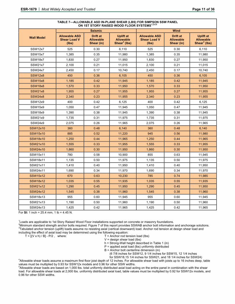
TABLE 7—ALLOWABLE ASD IN-PLANE SHEAR (LBS) FOR SIMPSON SSW PANEL ON 1ST STORY RAISED WOOD FLOOR SYSTEMS1,2,4,5
Wall Model
Seismic Wind
Allowable ASD Shear Load V
(lbs)
Drift at Allowable Shear (in)
Uplift at Allowable
Shear3 (lbs)
Allowable ASD Shear Load V
(lbs)
Drift at Allowable Shear (in)
Uplift at Allowable
Shear3 (lbs)
SSW12x7 525 0.30 6,110 525 0.30 6,110
SSW15x7 1,385 0.35 11,980 1,385 0.35 11,980
SSW18x7 1,830 0.27 11,950 1,830 0.27 11,950
SSW21x7 2,100 0.21 11,015 2,100 0.21 11,015
SSW24x7 2,450 0.17 10,740 2,450 0.17 10,740
SSW12x8 450 0.36 6,105 450 0.36 6,105
SSW15x8 1,185 0.42 11,945 1,185 0.42 11,945
SSW18x8 1,570 0.33 11,950 1,570 0.33 11,950
SSW21x8 1,955 0.27 11,955 1,955 0.27 11,955
SSW24x8 2,340 0.23 11,955 2,340 0.23 11,955
SSW12x9 400 0.42 6,125 400 0.42 6,125
SSW15x9 1,050 0.47 11,945 1,050 0.47 11,945
SSW18x9 1,390 0.38 11,945 1,390 0.38 11,945
SSW21x9 1,735 0.31 11,975 1,735 0.31 11,975
SSW24x9 2,075 0.26 11,965 2,075 0.26 11,965
SSW12x10 360 0.48 6,140 360 0.48 6,140
SSW15x10 885 0.52 11,220 945 0.56 11,980
SSW18x10 1,250 0.44 11,965 1,250 0.44 11,965
SSW21x10 1,555 0.33 11,955 1,555 0.33 11,955
SSW24x10 1,860 0.30 11,950 1,860 0.30 11,950
SSW15x11 780 0.58 10,900 855 0.63 11,945
SSW18x11 1,135 0.50 11,975 1,135 0.50 11,975
SSW21x11 1,410 0.40 11,950 1,410 0.40 11,950
SSW24x11 1,690 0.34 11,970 1,690 0.34 11,970
SSW15x12 670 0.63 10,230 785 0.74 11,985
SSW18x12 1,035 0.55 11,935 1,035 0.55 11,935
SSW21x12 1,290 0.45 11,950 1,290 0.45 11,950
SSW24x12 1,545 0.38 11,960 1,545 0.38 11,960
SSW18x13 955 0.60 11,945 955 0.60 11,945
SSW21x13 1,190 0.50 11,960 1,190 0.50 11,960
SSW24x13 1,425 0.42 11,965 1,425 0.42 11,965
For SI: 1 inch = 25.4 mm, 1 lb = 4.45 N.
1Loads are applicable to 1st Story Raised Wood Floor installations supported on concrete or masonry foundations. 2Minimum standard strength anchor bolts required. Figure 7 of this report provides SSWAB anchor bolt information and anchorage solutions. 3Tabulated anchor tension (uplift) loads assume no resisting axial (vertical downward) load. Anchor rod tension at design shear load and including the effect of axial load may be determined using the following equation:
T = [(V x h) / B] - P/2 , where: T = Anchor rod tension load (lbs) V = design shear load (lbs) h = Strong-Wall height described in Table 1 (in) P = applied axial load (lbs) uniformly distributed B = Anchor bolt centerline dimension (in) (6 7/8 inches for SSW12, 9 1/4 inches for SSW15, 12 1/4 inches for SSW18,15 1/4 inches for SSW21, and 18 1/4 inches for SSW24)
4Allowable shear loads assume a maximum first floor joist depth of 12 inches. For allowable shear load with joists up to 16 inches deep, table values must be multiplied by 0.93 for SSW12x models and 0.96 for other SSW widths. 5Allowable shear loads are based on 1,000 lbs. total uniformly distributed axial load acting on the entire panel in combination with the shear load. For allowable shear loads at 2,000 lbs. uniformly distributed axial load, table values must be multiplied by 0.92 for SSW12x models, and 0.96 for other SSW widths.
ESR-1679 | Most Widely Accepted and Trusted Page 12 of 36
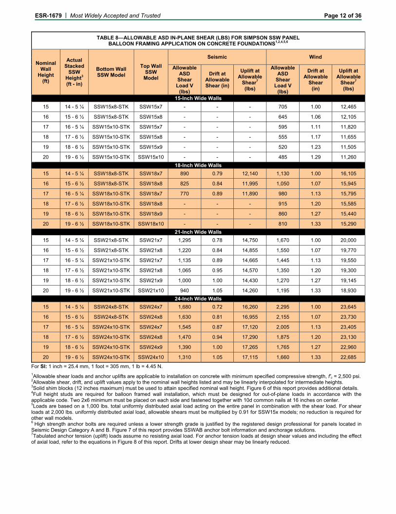
TABLE 8—ALLOWABLE ASD IN-PLANE SHEAR (LBS) FOR SIMPSON SSW PANEL BALLOON FRAMING APPLICATION ON CONCRETE FOUNDATIONS1,2,4,5,6
Nominal Wall
Height (ft)
Actual Stacked
SSW Height3 (ft - in)
Bottom Wall SSW Model
Top Wall SSW
Model
Seismic Wind
Allowable ASD
Shear Load V
(lbs)
Drift at Allowable Shear (in)
Uplift at Allowable
Shear7 (lbs)
Allowable ASD
Shear Load V
(lbs)
Drift at Allowable
Shear (in)
Uplift at Allowable
Shear7 (lbs)
15-Inch Wide Walls
15 14 - 5 ¼ SSW15x8-STK SSW15x7 - - - 705 1.00 12,465
16 15 - 6 ½ SSW15x8-STK SSW15x8 - - - 645 1.06 12,105
17 16 - 5 ¼ SSW15x10-STK SSW15x7 - - - 595 1.11 11,820
18 17 - 6 ½ SSW15x10-STK SSW15x8 - - - 555 1.17 11,655
19 18 - 6 ½ SSW15x10-STK SSW15x9 - - - 520 1.23 11,505
20 19 - 6 ½ SSW15x10-STK SSW15x10 - - - 485 1.29 11,260
18-Inch Wide Walls
15 14 - 5 ¼ SSW18x8-STK SSW18x7 890 0.79 12,140 1,130 1.00 16,105
16 15 - 6 ½ SSW18x8-STK SSW18x8 825 0.84 11,995 1,050 1.07 15,945
17 16 - 5 ¼ SSW18x10-STK SSW18x7 770 0.89 11,890 980 1.13 15,795
18 17 - 6 ½ SSW18x10-STK SSW18x8 - - - 915 1.20 15,585
19 18 - 6 ½ SSW18x10-STK SSW18x9 - - - 860 1.27 15,440
20 19 - 6 ½ SSW18x10-STK SSW18x10 - - - 810 1.33 15,290
21-Inch Wide Walls
15 14 - 5 ¼ SSW21x8-STK SSW21x7 1,295 0.78 14,750 1,670 1.00 20,000
16 15 - 6 ½ SSW21x8-STK SSW21x8 1,220 0.84 14,855 1,550 1.07 19,770
17 16 - 5 ¼ SSW21x10-STK SSW21x7 1,135 0.89 14,665 1,445 1.13 19,550
18 17 - 6 ½ SSW21x10-STK SSW21x8 1,065 0.95 14,570 1,350 1.20 19,300
19 18 - 6 ½ SSW21x10-STK SSW21x9 1,000 1.00 14,430 1,270 1.27 19,145
20 19 - 6 ½ SSW21x10-STK SSW21x10 940 1.05 14,260 1,195 1.33 18,930
24-Inch Wide Walls
15 14 - 5 ¼ SSW24x8-STK SSW24x7 1,680 0.72 16,260 2,295 1.00 23,645
16 15 - 6 ½ SSW24x8-STK SSW24x8 1,630 0.81 16,955 2,155 1.07 23,730
17 16 - 5 ¼ SSW24x10-STK SSW24x7 1,545 0.87 17,120 2,005 1.13 23,405
18 17 - 6 ½ SSW24x10-STK SSW24x8 1,470 0.94 17,290 1,875 1.20 23,130
19 18 - 6 ½ SSW24x10-STK SSW24x9 1,390 1.00 17,265 1,765 1.27 22,960
20 19 - 6 ½ SSW24x10-STK SSW24x10 1,310 1.05 17,115 1,660 1.33 22,685
For SI: 1 inch = 25.4 mm, 1 foot = 305 mm, 1 lb = 4.45 N.
1Allowable shear loads and anchor uplifts are applicable to installation on concrete with minimum specified compressive strength, f'c = 2,500 psi. 2Allowable shear, drift, and uplift values apply to the nominal wall heights listed and may be linearly interpolated for intermediate heights. 3Solid shim blocks (12 inches maximum) must be used to attain specified nominal wall height. Figure 6 of this report provides additional details. 4Full height studs are required for balloon framed wall installation, which must be designed for out-of-plane loads in accordance with the applicable code. Two 2x6 minimum must be placed on each side and fastened together with 10d common nails at 16 inches on center. 5Loads are based on a 1,000 lbs. total uniformly distributed axial load acting on the entire panel in combination with the shear load. For shear loads at 2,000 lbs. uniformly distributed axial load, allowable shears must be multiplied by 0.91 for SSW15x models; no reduction is required for other wall models. 6 High strength anchor bolts are required unless a lower strength grade is justified by the registered design professional for panels located in Seismic Design Category A and B. Figure 7 of this report provides SSWAB anchor bolt information and anchorage solutions. 7Tabulated anchor tension (uplift) loads assume no resisting axial load. For anchor tension loads at design shear values and including the effect of axial load, refer to the equations in Figure 8 of this report. Drifts at lower design shear may be linearly reduced.
ESR-1679 | Most Widely Accepted and Trusted Page 13 of 36
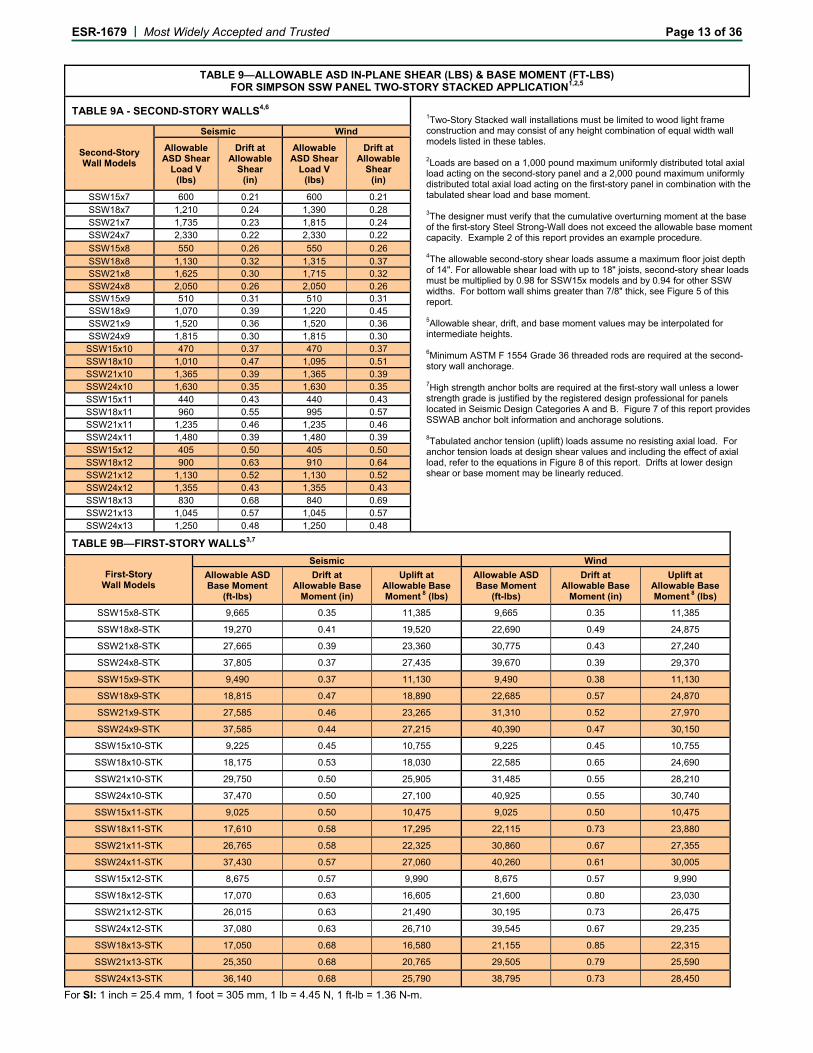
TABLE 9—ALLOWABLE ASD IN-PLANE SHEAR (LBS) & BASE MOMENT (FT-LBS)
FOR SIMPSON SSW PANEL TWO-STORY STACKED APPLICATION1,2,5
TABLE 9A - SECOND-STORY WALLS4,6
Second-Story Wall Models
Seismic Wind
Allowable ASD Shear
Load V (lbs)
Drift at Allowable
Shear (in)
Allowable ASD Shear
Load V (lbs)
Drift at Allowable
Shear (in)
SSW15x7 600 0.21 600 0.21 SSW18x7 1,210 0.24 1,390 0.28 SSW21x7 1,735 0.23 1,815 0.24 SSW24x7 2,330 0.22 2,330 0.22 SSW15x8 550 0.26 550 0.26 SSW18x8 1,130 0.32 1,315 0.37 SSW21x8 1,625 0.30 1,715 0.32 SSW24x8 2,050 0.26 2,050 0.26 SSW15x9 510 0.31 510 0.31 SSW18x9 1,070 0.39 1,220 0.45 SSW21x9 1,520 0.36 1,520 0.36 SSW24x9 1,815 0.30 1,815 0.30 SSW15x10 470 0.37 470 0.37 SSW18x10 1,010 0.47 1,095 0.51 SSW21x10 1,365 0.39 1,365 0.39 SSW24x10 1,630 0.35 1,630 0.35 SSW15x11 440 0.43 440 0.43 SSW18x11 960 0.55 995 0.57 SSW21x11 1,235 0.46 1,235 0.46 SSW24x11 1,480 0.39 1,480 0.39 SSW15x12 405 0.50 405 0.50 SSW18x12 900 0.63 910 0.64 SSW21x12 1,130 0.52 1,130 0.52 SSW24x12 1,355 0.43 1,355 0.43 SSW18x13 830 0.68 840 0.69 SSW21x13 1,045 0.57 1,045 0.57 SSW24x13 1,250 0.48 1,250 0.48
TABLE 9B—FIRST-STORY WALLS3,7
First-Story Wall Models
Seismic Wind
Allowable ASD Base Moment
(ft-lbs)
Drift at Allowable Base
Moment (in)
Uplift at Allowable Base Moment 8 (lbs)
Allowable ASD Base Moment
(ft-lbs)
Drift at Allowable Base
Moment (in)
Uplift at Allowable Base Moment 8 (lbs)
SSW15x8-STK 9,665 0.35 11,385 9,665 0.35 11,385
SSW18x8-STK 19,270 0.41 19,520 22,690 0.49 24,875
SSW21x8-STK 27,665 0.39 23,360 30,775 0.43 27,240
SSW24x8-STK 37,805 0.37 27,435 39,670 0.39 29,370
SSW15x9-STK 9,490 0.37 11,130 9,490 0.38 11,130
SSW18x9-STK 18,815 0.47 18,890 22,685 0.57 24,870
SSW21x9-STK 27,585 0.46 23,265 31,310 0.52 27,970
SSW24x9-STK 37,585 0.44 27,215 40,390 0.47 30,150
SSW15x10-STK 9,225 0.45 10,755 9,225 0.45 10,755
SSW18x10-STK 18,175 0.53 18,030 22,585 0.65 24,690
SSW21x10-STK 29,750 0.50 25,905 31,485 0.55 28,210
SSW24x10-STK 37,470 0.50 27,100 40,925 0.55 30,740
SSW15x11-STK 9,025 0.50 10,475 9,025 0.50 10,475
SSW18x11-STK 17,610 0.58 17,295 22,115 0.73 23,880
SSW21x11-STK 26,765 0.58 22,325 30,860 0.67 27,355
SSW24x11-STK 37,430 0.57 27,060 40,260 0.61 30,005
SSW15x12-STK 8,675 0.57 9,990 8,675 0.57 9,990
SSW18x12-STK 17,070 0.63 16,605 21,600 0.80 23,030
SSW21x12-STK 26,015 0.63 21,490 30,195 0.73 26,475
SSW24x12-STK 37,080 0.63 26,710 39,545 0.67 29,235
SSW18x13-STK 17,050 0.68 16,580 21,155 0.85 22,315
SSW21x13-STK 25,350 0.68 20,765 29,505 0.79 25,590
SSW24x13-STK 36,140 0.68 25,790 38,795 0.73 28,450
For SI: 1 inch = 25.4 mm, 1 foot = 305 mm, 1 lb = 4.45 N, 1 ft-lb = 1.36 N-m.
1Two-Story Stacked wall installations must be limited to wood light frame construction and may consist of any height combination of equal width wall models listed in these tables. 2Loads are based on a 1,000 pound maximum uniformly distributed total axial load acting on the second-story panel and a 2,000 pound maximum uniformly distributed total axial load acting on the first-story panel in combination with the tabulated shear load and base moment. 3The designer must verify that the cumulative overturning moment at the base of the first-story Steel Strong-Wall does not exceed the allowable base moment capacity. Example 2 of this report provides an example procedure. 4The allowable second-story shear loads assume a maximum floor joist depth of 14". For allowable shear load with up to 18" joists, second-story shear loads must be multiplied by 0.98 for SSW15x models and by 0.94 for other SSW widths. For bottom wall shims greater than 7/8" thick, see Figure 5 of this report. 5Allowable shear, drift, and base moment values may be interpolated for intermediate heights. 6Minimum ASTM F 1554 Grade 36 threaded rods are required at the second-story wall anchorage. 7High strength anchor bolts are required at the first-story wall unless a lower strength grade is justified by the registered design professional for panels located in Seismic Design Categories A and B. Figure 7 of this report provides SSWAB anchor bolt information and anchorage solutions. 8Tabulated anchor tension (uplift) loads assume no resisting axial load. For anchor tension loads at design shear values and including the effect of axial load, refer to the equations in Figure 8 of this report. Drifts at lower design shear or base moment may be linearly reduced.
ESR-1679 | Most Widely Accepted and Trusted Page 14 of 36
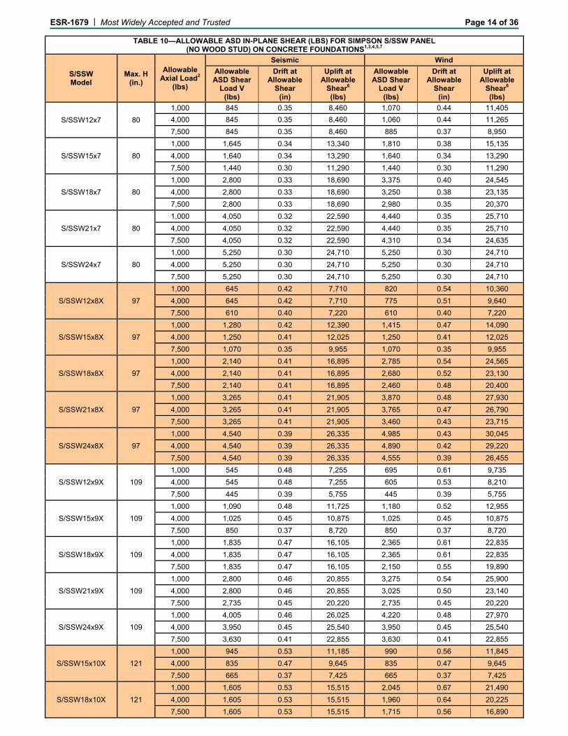
TABLE 10—ALLOWABLE ASD IN-PLANE SHEAR (LBS) FOR SIMPSON S/SSW PANEL (NO WOOD STUD) ON CONCRETE FOUNDATIONS1,3,4,5,7
S/SSW Model
Max. H (in.)
Allowable Axial Load2
(lbs)
Seismic Wind
Allowable ASD Shear
Load V (lbs)
Drift at Allowable
Shear (in)
Uplift at Allowable
Shear6 (lbs)
Allowable ASD Shear
Load V (lbs)
Drift at Allowable
Shear (in)
Uplift at Allowable
Shear6 (lbs)
S/SSW12x7 80
1,000 845 0.35 8,460 1,070 0.44 11,405
4,000 845 0.35 8,460 1,060 0.44 11,265
7,500 845 0.35 8,460 885 0.37 8,950
S/SSW15x7 80
1,000 1,645 0.34 13,340 1,810 0.38 15,135
4,000 1,640 0.34 13,290 1,640 0.34 13,290
7,500 1,440 0.30 11,290 1,440 0.30 11,290
S/SSW18x7 80
1,000 2,800 0.33 18,690 3,375 0.40 24,545
4,000 2,800 0.33 18,690 3,250 0.38 23,135
7,500 2,800 0.33 18,690 2,980 0.35 20,370
S/SSW21x7 80
1,000 4,050 0.32 22,590 4,440 0.35 25,710
4,000 4,050 0.32 22,590 4,440 0.35 25,710
7,500 4,050 0.32 22,590 4,310 0.34 24,635
S/SSW24x7 80
1,000 5,250 0.30 24,710 5,250 0.30 24,710
4,000 5,250 0.30 24,710 5,250 0.30 24,710
7,500 5,250 0.30 24,710 5,250 0.30 24,710
S/SSW12x8X 97
1,000 645 0.42 7,710 820 0.54 10,360
4,000 645 0.42 7,710 775 0.51 9,640
7,500 610 0.40 7,220 610 0.40 7,220
S/SSW15x8X 97
1,000 1,280 0.42 12,390 1,415 0.47 14,090
4,000 1,250 0.41 12,025 1,250 0.41 12,025
7,500 1,070 0.35 9,955 1,070 0.35 9,955
S/SSW18x8X 97
1,000 2,140 0.41 16,895 2,785 0.54 24,565
4,000 2,140 0.41 16,895 2,680 0.52 23,130
7,500 2,140 0.41 16,895 2,460 0.48 20,400
S/SSW21x8X 97
1,000 3,265 0.41 21,905 3,870 0.48 27,930
4,000 3,265 0.41 21,905 3,765 0.47 26,790
7,500 3,265 0.41 21,905 3,460 0.43 23,715
S/SSW24x8X 97
1,000 4,540 0.39 26,335 4,985 0.43 30,045
4,000 4,540 0.39 26,335 4,890 0.42 29,220
7,500 4,540 0.39 26,335 4,555 0.39 26,455
S/SSW12x9X 109
1,000 545 0.48 7,255 695 0.61 9,735
4,000 545 0.48 7,255 605 0.53 8,210
7,500 445 0.39 5,755 445 0.39 5,755
S/SSW15x9X 109
1,000 1,090 0.48 11,725 1,180 0.52 12,955
4,000 1,025 0.45 10,875 1,025 0.45 10,875
7,500 850 0.37 8,720 850 0.37 8,720
S/SSW18x9X 109
1,000 1,835 0.47 16,105 2,365 0.61 22,835
4,000 1,835 0.47 16,105 2,365 0.61 22,835
7,500 1,835 0.47 16,105 2,150 0.55 19,890
S/SSW21x9X 109
1,000 2,800 0.46 20,855 3,275 0.54 25,900
4,000 2,800 0.46 20,855 3,025 0.50 23,140
7,500 2,735 0.45 20,220 2,735 0.45 20,220
S/SSW24x9X 109
1,000 4,005 0.46 26,025 4,220 0.48 27,970
4,000 3,950 0.45 25,540 3,950 0.45 25,540
7,500 3,630 0.41 22,855 3,630 0.41 22,855
S/SSW15x10X 121
1,000 945 0.53 11,185 990 0.56 11,845
4,000 835 0.47 9,645 835 0.47 9,645
7,500 665 0.37 7,425 665 0.37 7,425
S/SSW18x10X 121
1,000 1,605 0.53 15,515 2,045 0.67 21,490
4,000 1,605 0.53 15,515 1,960 0.64 20,225
7,500 1,605 0.53 15,515 1,715 0.56 16,890
ESR-1679 | Most Widely Accepted and Trusted Page 15 of 36
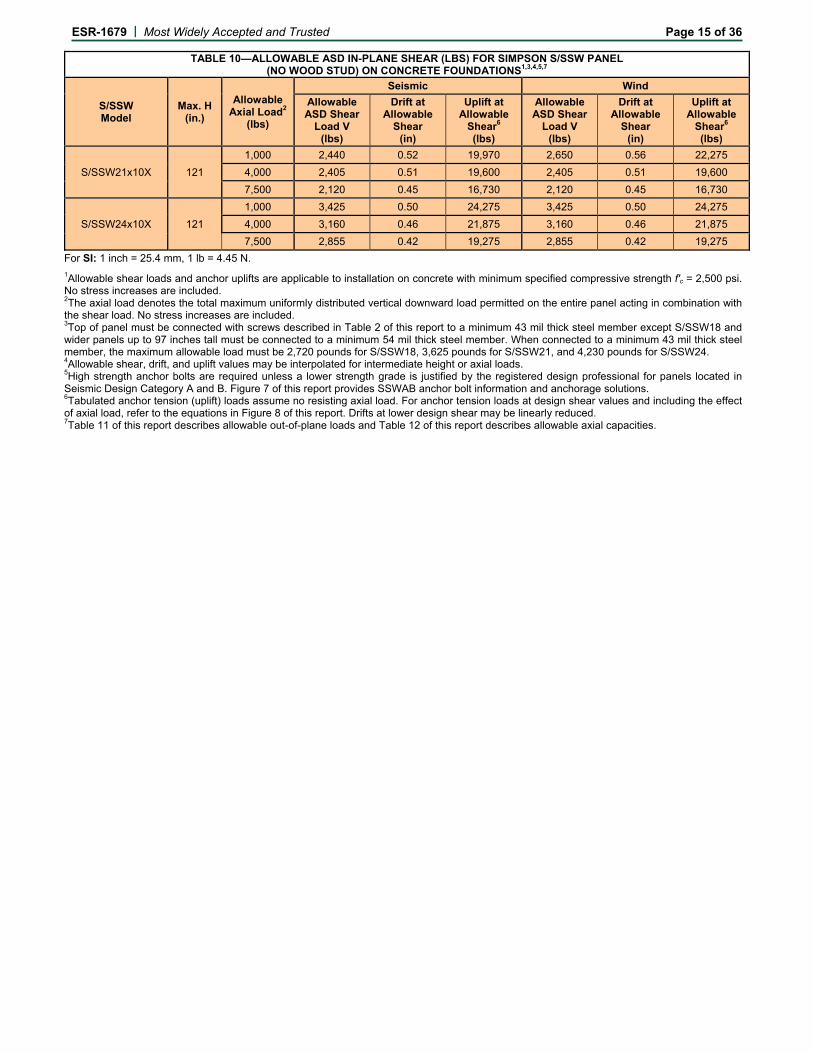
TABLE 10—ALLOWABLE ASD IN-PLANE SHEAR (LBS) FOR SIMPSON S/SSW PANEL (NO WOOD STUD) ON CONCRETE FOUNDATIONS1,3,4,5,7
S/SSW Model
Max. H (in.)
Allowable Axial Load2
(lbs)
Seismic Wind
Allowable ASD Shear
Load V (lbs)
Drift at Allowable
Shear (in)
Uplift at Allowable
Shear6 (lbs)
Allowable ASD Shear
Load V (lbs)
Drift at Allowable
Shear (in)
Uplift at Allowable
Shear6 (lbs)
S/SSW21x10X 121
1,000 2,440 0.52 19,970 2,650 0.56 22,275
4,000 2,405 0.51 19,600 2,405 0.51 19,600
7,500 2,120 0.45 16,730 2,120 0.45 16,730
S/SSW24x10X 121
1,000 3,425 0.50 24,275 3,425 0.50 24,275
4,000 3,160 0.46 21,875 3,160 0.46 21,875
7,500 2,855 0.42 19,275 2,855 0.42 19,275
For SI: 1 inch = 25.4 mm, 1 lb = 4.45 N.
1Allowable shear loads and anchor uplifts are applicable to installation on concrete with minimum specified compressive strength f'c = 2,500 psi. No stress increases are included. 2The axial load denotes the total maximum uniformly distributed vertical downward load permitted on the entire panel acting in combination with the shear load. No stress increases are included. 3Top of panel must be connected with screws described in Table 2 of this report to a minimum 43 mil thick steel member except S/SSW18 and wider panels up to 97 inches tall must be connected to a minimum 54 mil thick steel member. When connected to a minimum 43 mil thick steel member, the maximum allowable load must be 2,720 pounds for S/SSW18, 3,625 pounds for S/SSW21, and 4,230 pounds for S/SSW24. 4Allowable shear, drift, and uplift values may be interpolated for intermediate height or axial loads. 5High strength anchor bolts are required unless a lower strength grade is justified by the registered design professional for panels located in Seismic Design Category A and B. Figure 7 of this report provides SSWAB anchor bolt information and anchorage solutions. 6Tabulated anchor tension (uplift) loads assume no resisting axial load. For anchor tension loads at design shear values and including the effect of axial load, refer to the equations in Figure 8 of this report. Drifts at lower design shear may be linearly reduced. 7Table 11 of this report describes allowable out-of-plane loads and Table 12 of this report describes allowable axial capacities.
ESR-1679 | Most Widely Accepted and Trusted Page 16 of 36
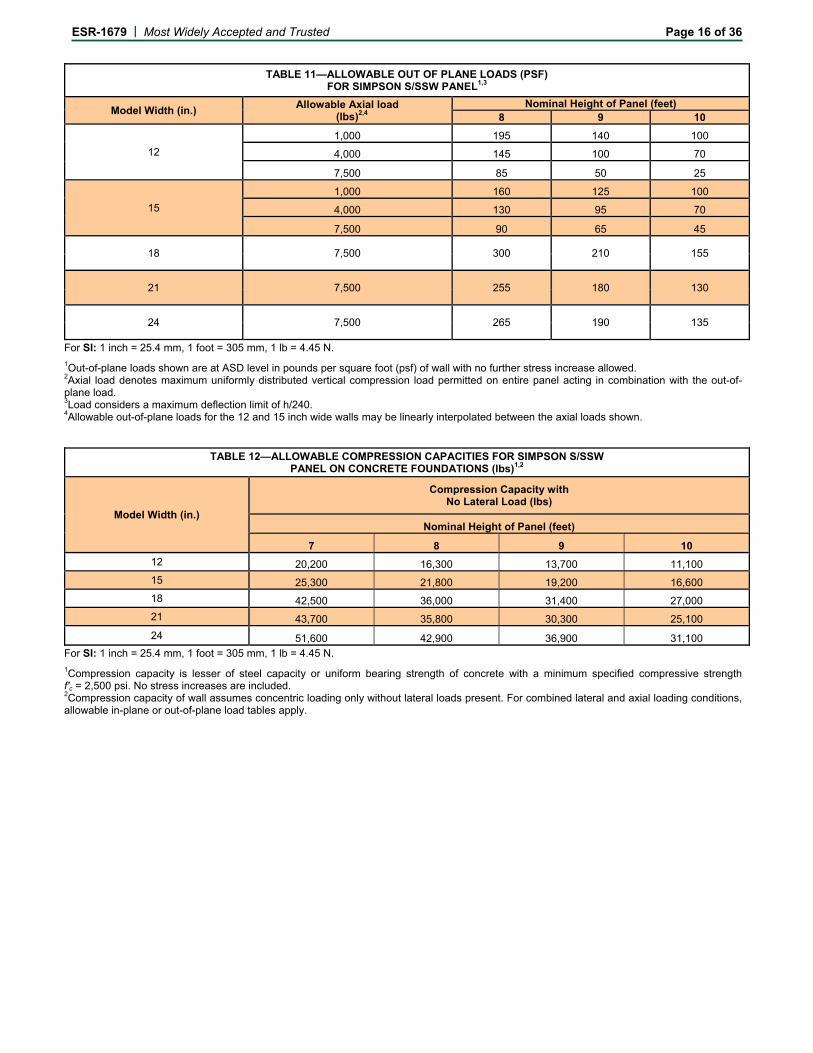
TABLE 11—ALLOWABLE OUT OF PLANE LOADS (PSF) FOR SIMPSON S/SSW PANEL1,3
Model Width (in.) Allowable Axial load
(lbs)2,4 Nominal Height of Panel (feet)
8 9 10
12
1,000 195 140 100
4,000 145 100 70
7,500 85 50 25
15
1,000 160 125 100
4,000 130 95 70
7,500 90 65 45
18 7,500 300 210 155
21 7,500 255 180 130
24 7,500 265 190 135
For SI: 1 inch = 25.4 mm, 1 foot = 305 mm, 1 lb = 4.45 N.
1Out-of-plane loads shown are at ASD level in pounds per square foot (psf) of wall with no further stress increase allowed.
2Axial load denotes maximum uniformly distributed vertical compression load permitted on entire panel acting in combination with the out-of-plane load. 3Load considers a maximum deflection limit of h/240. 4Allowable out-of-plane loads for the 12 and 15 inch wide walls may be linearly interpolated between the axial loads shown.
TABLE 12—ALLOWABLE COMPRESSION CAPACITIES FOR SIMPSON S/SSW PANEL ON CONCRETE FOUNDATIONS (lbs)1,2
Model Width (in.)
Compression Capacity with No Lateral Load (lbs)
Nominal Height of Panel (feet)
7 8 9 10
12 20,200 16,300 13,700 11,100
15 25,300 21,800 19,200 16,600
18 42,500 36,000 31,400 27,000
21 43,700 35,800 30,300 25,100
24 51,600 42,900 36,900 31,100
For SI: 1 inch = 25.4 mm, 1 foot = 305 mm, 1 lb = 4.45 N.
1Compression capacity is lesser of steel capacity or uniform bearing strength of concrete with a minimum specified compressive strength f'c = 2,500 psi. No stress increases are included. 2Compression capacity of wall assumes concentric loading only without lateral loads present. For combined lateral and axial loading conditions, allowable in-plane or out-of-plane load tables apply.
ESR-1679 | Most Widely Accepted and Trusted Page 17 of 36
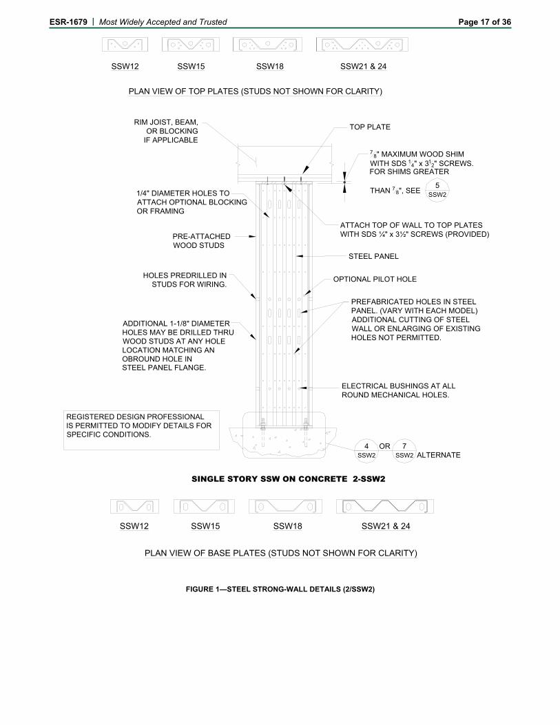
SSW12 SSW15 SSW18 SSW21 & 24
PLAN VIEW OF TOP PLATES (STUDS NOT SHOWN FOR CLARITY)
ADDITIONAL 1-1/8" DIAMETER HOLES MAY BE DRILLED THRU WOOD STUDS AT ANY HOLELOCATION MATCHING ANOBROUND HOLE IN
PRE-ATTACHEDWOOD STUDS
1/4" DIAMETER HOLES TO ATTACH OPTIONAL BLOCKINGOR FRAMING
HOLES PREDRILLED INSTUDS FOR WIRING.
PREFABRICATED HOLES IN STEEL PANEL. (VARY WITH EACH MODEL) ADDITIONAL CUTTING OF STEELWALL OR ENLARGING OF EXISTING HOLES NOT PERMITTED.
STEEL PANEL
ELECTRICAL BUSHINGS AT ALL ROUND MECHANICAL HOLES.
OPTIONAL PILOT HOLE
OR ALTERNATE
TOP PLATE
ATTACH TOP OF WALL TO TOP PLATES WITH SDS ¼" x 3½" SCREWS (PROVIDED)
78" MAXIMUM WOOD SHIM
WITH SDS 14" x 312" SCREWS.
FOR SHIMS GREATER
THAN 7 8", SEE
RIM JOIST, BEAM,OR BLOCKING
IF APPLICABLE
STEEL PANEL FLANGE.
5SSW2
4SSW2
7SSW2
SINGLE STORY SSW ON CONCRETE 2-SSW2
REGISTERED DESIGN PROFESSIONALIS PERMITTED TO MODIFY DETAILS FORSPECIFIC CONDITIONS.
SSW15SSW12 SSW18 SSW21 & 24
PLAN VIEW OF BASE PLATES (STUDS NOT SHOWN FOR CLARITY)
FIGURE 1—STEEL STRONG-WALL DETAILS (2/SSW2)
ESR-1679 | Most Widely Accepted and Trusted Page 18 of 36
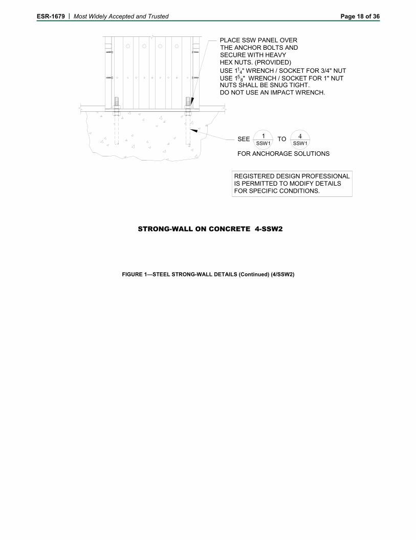
PLACE SSW PANEL OVER THE ANCHOR BOLTS AND SECURE WITH HEAVY HEX NUTS. (PROVIDED) USE 11
4" WRENCH / SOCKET FOR 3/4" NUT USE 15
8" WRENCH / SOCKET FOR 1" NUTNUTS SHALL BE SNUG TIGHT. DO NOT USE AN IMPACT WRENCH.
SEE TO
FOR ANCHORAGE SOLUTIONS
STRONG-WALL ON CONCRETE 4-SSW2
REGISTERED DESIGN PROFESSIONALIS PERMITTED TO MODIFY DETAILS FOR SPECIFIC CONDITIONS.
SSW11
SSW1 4
FIGURE 1—STEEL STRONG-WALL DETAILS (Continued) (4/SSW2)
ESR-1679 | Most Widely Accepted and Trusted Page 19 of 36
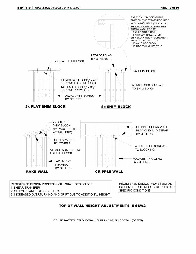
2x FLAT SHIM BLOCK
ATTACH WITH SDS14" x 41
2" SCREWS TO SHIM BLOCKINSTEAD OF SDS1
4" x 312"
SCREWS PROVIDED.
REGISTERED DESIGN PROFESSIONAL SHALL DESIGN FOR:1. SHEAR TRANSFER2. OUT OF PLANE LOADING EFFECT3. INCREASED OVERTURNING AND DRIFT DUE TO ADDITIONAL HEIGHT.
CRIPPLE WALL
ADJACENT FRAMING BY OTHERS
LTP4 SPACING BY OTHERS
4x SHIM BLOCK
ATTACH SDS SCREWSTO SHIM BLOCK
4x SHIM BLOCK
CRIPPLE SHEAR WALL, BLOCKING AND STRAP BY OTHERS
ATTACH SDS SCREWS TO BLOCKING
ADJACENT FRAMINGBY OTHERS
2x FLAT SHIM BLOCK
LTP4 SPACING BY OTHERS
4x SHAPEDSHIM BLOCK(12" MAX. DEPTHAT TALL END)
ATTACH SDS SCREWSTO SHIM BLOCK
ADJACENTFRAMINGBY OTHERS
RAKE WALL
FOR 8" TO 12" BLOCK DEPTHS:SIMPSON CS16 STRAPS REQUIRED
WITH 10dx1½ NAILS (0.148" x 1.5")SHIM BLOCK HEIGHTS GREATERTHAN 8" AND UP TO 10": 8 NAILS INTO BLOCK 8 INTO SSW NAILER STUDSHIM BLOCK HEIGHTS GREATERTHAN 10" AND UP TO 12": 10 NAILS INTO BLOCK 10 INTO SSW NAILER STUD
TOP OF WALL HEIGHT ADJUSTMENTS 5-SSW2
REGISTERED DESIGN PROFESSIONALIS PERMITTED TO MODIFY DETAILS FORSPECIFIC CONDITIONS.
FIGURE 2—STEEL STRONG-WALL SHIM AND CRIPPLE DETAIL (5/SSW2)
ESR-1679 | Most Widely Accepted and Trusted Page 20 of 36
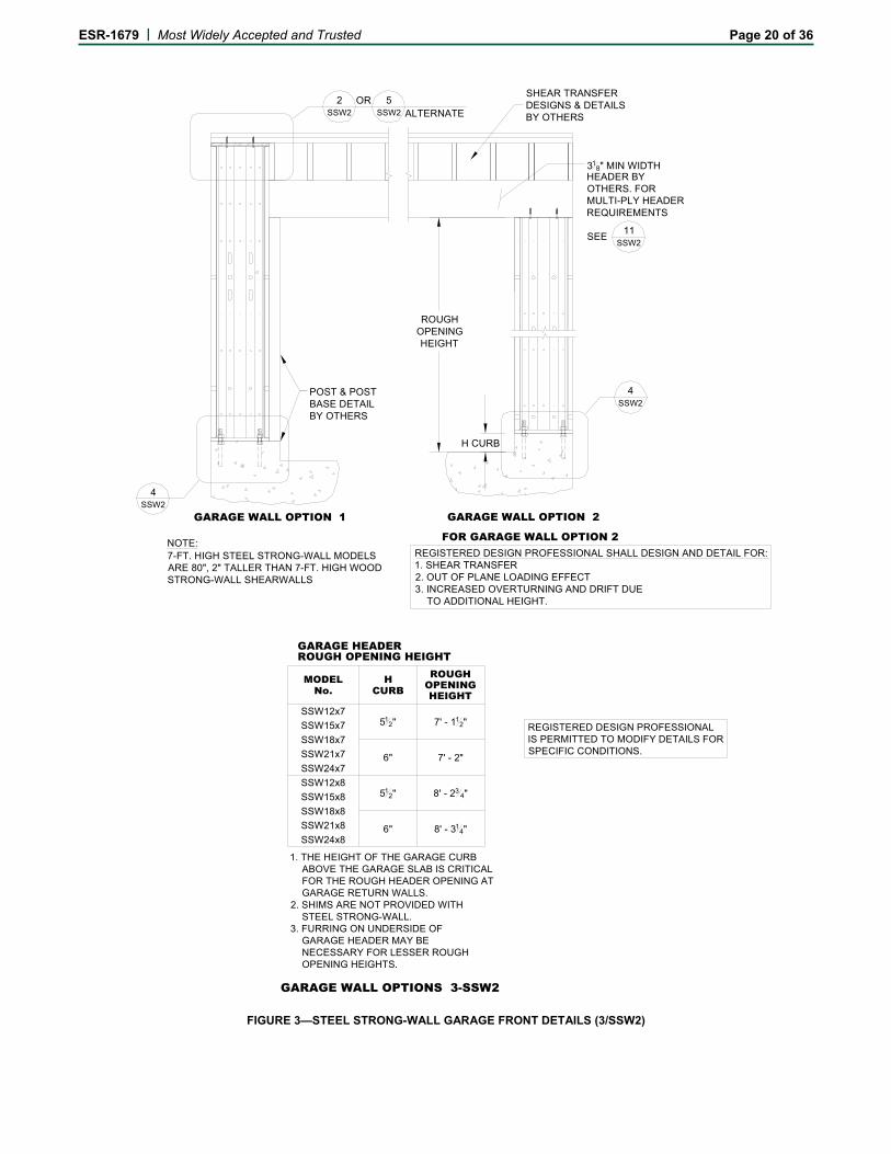
GARAGE WALL OPTION 1
POST & POSTBASE DETAILBY OTHERS
GARAGE WALL OPTION 2
SHEAR TRANSFERDESIGNS & DETAILS BY OTHERS
7-FT. HIGH STEEL STRONG-WALL MODELSARE 80", 2" TALLER THAN 7-FT. HIGH WOODSTRONG-WALL SHEARWALLS
REGISTERED DESIGN PROFESSIONAL SHALL DESIGN AND DETAIL FOR:1. SHEAR TRANSFER2. OUT OF PLANE LOADING EFFECT3. INCREASED OVERTURNING AND DRIFT DUE TO ADDITIONAL HEIGHT.
FOR GARAGE WALL OPTION 2
ORALTERNATE
NOTE:
318" MIN WIDTH
HEADER BYOTHERS. FOR MULTI-PLY HEADERREQUIREMENTS
SEE
SSW24x7
SSW21x7
CURBH
SSW18x7
SSW15x7
SSW12x7
OPENINGHEIGHT
ROUGH
SSW15x8
SSW12x8
SSW18x8
SSW21x8
SSW24x8
512"
6"
512"
6"
7' - 112"
7' - 2"
8' - 234"
8' - 314"
GARAGE HEADERROUGH OPENING HEIGHT
No.MODEL
1. THE HEIGHT OF THE GARAGE CURB ABOVE THE GARAGE SLAB IS CRITICAL FOR THE ROUGH HEADER OPENING AT GARAGE RETURN WALLS.2. SHIMS ARE NOT PROVIDED WITH STEEL STRONG-WALL.3. FURRING ON UNDERSIDE OF GARAGE HEADER MAY BE NECESSARY FOR LESSER ROUGH OPENING HEIGHTS.
H CURB
ROUGHOPENINGHEIGHT
11SSW2
2SSW2
4SSW2
SSW2
5SSW2
GARAGE WALL OPTIONS 3-SSW2
4
REGISTERED DESIGN PROFESSIONAL IS PERMITTED TO MODIFY DETAILS FORSPECIFIC CONDITIONS.
FIGURE 3—STEEL STRONG-WALL GARAGE FRONT DETAILS (3/SSW2)
ESR-1679 | Most Widely Accepted and Trusted Page 21 of 36
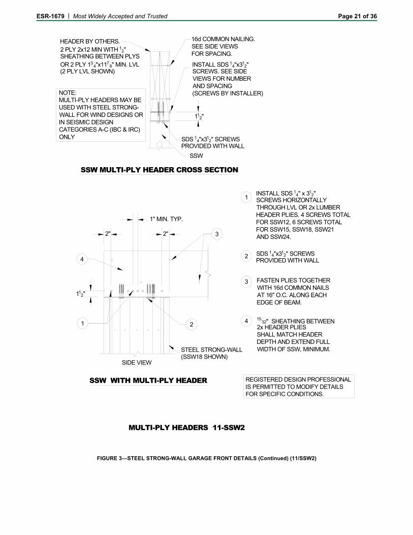
SSW MULTI-PLY HEADER CROSS SECTION
SSW WITH MULTI-PLY HEADER
SDS 14"x312" SCREWS
PROVIDED WITH WALL
16d COMMON NAILING. SEE SIDE VIEWS FOR SPACING.
STEEL STRONG-WALL(SSW18 SHOWN)
INSTALL SDS 14"x312"
SCREWS. SEE SIDEVIEWS FOR NUMBERAND SPACING(SCREWS BY INSTALLER)
MULTI-PLY HEADERS 11-SSW2
2" 2"
112"
1
4
SIDE VIEW
2
MULTI-PLY HEADERS MAY BEUSED WITH STEEL STRONG-WALL FOR WIND DESIGNS ORIN SEISMIC DESIGNCATEGORIES A-C (IBC & IRC)ONLY
HEADER BY OTHERS.2 PLY 2x12 MIN WITH 12"SHEATHING BETWEEN PLYSOR 2 PLY 13
4"x1178" MIN. LVL
(2 PLY LVL SHOWN)
NOTE:
1" MIN. TYP.
SSW
112"
3
INSTALL SDS 14" x 312"
SCREWS HORIZONTALLYTHROUGH LVL OR 2x LUMBERHEADER PLIES. 4 SCREWS TOTALFOR SSW12, 6 SCREWS TOTAL FOR SSW15, SSW18, SSW21AND SSW24.
1532" SHEATHING BETWEEN
2x HEADER PLIESSHALL MATCH HEADERDEPTH AND EXTEND FULLWIDTH OF SSW, MINIMUM.
FASTEN PLIES TOGETHERWITH 16d COMMON NAILS AT 16" O.C. ALONG EACHEDGE OF BEAM.
SDS 14"x312" SCREWS
PROVIDED WITH WALL
REGISTERED DESIGN PROFESSIONALIS PERMITTED TO MODIFY DETAILS FOR SPECIFIC CONDITIONS.
4
3
2
1
FIGURE 3—STEEL STRONG-WALL GARAGE FRONT DETAILS (Continued) (11/SSW2)
ESR-1679 | Most Widely Accepted and Trusted Page 22 of 36
COUPLER NUT
SOLID BLOCKING BELOW
PLACE SSW PANEL OVER THREADEDRODS AND SECURE WITH HEAVY HEXNUTS (PROVIDED). USE1 1/4" WRENCH/SOCKET FOR 3/4" NUT1 5/8" WRENCH/SOCKET FOR 1" NUTSET LOWER NUT FLUSH
WITH TOP OF SHEATHING.
INTERIOR ELEVATION
EXTERIOR ELEVATION
SHEAR TRANSFER
WITH SSW_-1KT)
SHEAR TRANSFERBY OTHERS(LTP4 SHOWN)
RIM JOIST
SIMPSON A34 EACH SIDE
SSW BASE PLATE SHALLSIT FLUSH & LEVEL ON NUTS.
2"x2"x1" DEEP MAX. INSHEATHING & RIM JOIST.
NUTS SHALL BE SNUG TIGHT.DO NOT USE AN IMPACT WRENCH.
STEEL STRONG-WALL
#14 SCREWS TOPANEL (PROVIDED
10d COMMONS
FIRST FLOOR AT WOOD FRAMING NOTES:1. USE WOOD FIRST-FLOOR ALLOWABLE LOAD TABLES FOR THIS INSTALLATION.
2. USE ALTERNATE DETAIL TO ACHIEVE MAXIMUM ON CONCRETE ALLOWABLE LOADS.3. FOR TWO-STORY STACKED STEEL STRONG-WALLS WITH WOOD
FIRST FLOOR,USE ALTERNATE DETAIL .
4. REGISTERED DESIGN PROFESSIONAL SHALL DESIGN FOR SHEAR TRANSFER FROM RIM JOIST TO SILL PLATE AND SILL PLATE TO FOUNDATION.
AND THREADED
STEELSTRONG-WALL
JOIST HANGER(IF REQUIRED)
SECTION
PLATE. (PROVIDED
BLOCKING BELOW SSW
WITH SSW_-1KT)
TO FRAMING
FLOOR FRAMING AT 2'-0"OC MAX. WHERE FRAMINGIS PARALLEL TO WALL,INSTALL BLOCKING WITHIN6" OF EACH END OF SSW.BLOCKING DEPTH SHALLMATCH FLOOR FRAMING.
RODS (INCLUDEDWITH SSW_-1KT)
DEEP HOLE OR NOTCHDRILL 2" DIAMETER x 1"
NO.MODEL
15
WIDTH(in)
WALL
WOOD FIRST-FLOORWALL CONNECTION KIT
SSW24-1KT
SSW21-1KT
SSW18-1KT
SSW15-1KT
CONTENTS
EACH KIT CONTAINS:(1) SHEAR TRANSFER PLATE (with #14 SCREWS)(2) 3/4" x 18" OR 1" x 18" THREADED RODS (ASTM A36)(2) COUPLER NUTS(2) HEAVY HEX NUTSINSTALLATION INSTRUCTIONS
12 SSW12-1KT
SSW1 FORANCHORAGESOLUTIONS.
SEE SHEET18
21
24
ORDER FIRST FLOOR CONNECTOR KIT SEPARATELY.MODEL SSW_-1KT . EXAMPLE: SSW21-1KT
(NOT PROVIDED)
FIRST FLOOR AT WOOD FRAMING 10-SSW2
7SSW2
7SSW2
REGISTERED DESIGN PROFESSIONALIS PERMITTED TO MODIFY DETAILS FOR SPECIFIC CONDITIONS.
FIGURE 4—STEEL STRONG-WALL WOOD FLOOR DETAILS (10/SSW2)

ESR-1679 | Most Widely Accepted and Trusted Page 23 of 36
STEEL STRONG-WALL
JOIST HANGER(IF REQUIRED)
NAILING BY OTHERS
SECTION
FRAMING BYOTHERS,TYPICAL
PLACE SSW PANEL OVER THE ANCHOR BOLTS AND SECURE
WITH HEAVY HEX NUTS (PROVIDED).
USE 1 1 4 " WRENCH / SOCKET FOR 3/4" NUT USE 1 5 8 " WRENCH / SOCKET FOR 1" NUT
NUTS SHALL BE SNUG TIGHT.DO NOT USE AN IMPACT WRENCH.
ALTERNATE 1ST FLOOR WOOD FRAMING 7-SSW2
REGISTERED DESIGN PROFESSIONALIS PERMITTED TO MODIFY DETAILS FOR SPECIFIC CONDITIONS.
SEE TO
FOR ANCHORAGE SOLUTIONS SSW1
1SSW1
4
FIGURE 4—STEEL STRONG-WALL WOOD FLOOR DETAILS (Continued) (7/SSW2)
ESR-1679 | Most Widely Accepted and Trusted Page 24 of 36
ORALTERNATE
ORDER TWO-STORYSTACKED WALL CONNECTOR KITSEPARATELY.MODEL SSW_-2KT .EXAMPLE: SSW21-2KT
FIRST STORY WALL:ADD -STK TO MODELNAME.EXAMPLE: SSW21x9-STK
STANDARDSTEEL STRONG-WALLAT 2nd FLOOR WALL
ORALTERNATE
SSW-STK OPTION(FACTORY INSTALLED)
H
W
TWO-STORY STACKED 6-SSW2
SSW2
4SSW2
7
SSW2
2SSW2
5
SSW2
9
REGISTERED DESIGN PROFESSIONALIS PERMITTED TO MODIFY DETAILS FOR SPECIFIC CONDITIONS.
FIGURE 5—STEEL STRONG-WALL TWO-STORY STACKED DETAILS (6/SSW2)
ESR-1679 | Most Widely Accepted and Trusted Page 25 of 36
1" DIAMETER
DRILL 1 1/16" MAX DIAMETERHOLE IN DOUBLE TOPPLATE FOR RODS
SOLID BLOCKING BELOW
INTERIOR ELEVATION
EXTERIOR ELEVATION
RIM JOIST
ATTACH TOP OF SSW TOTOP PLATES WITH
SIMPSON A34 EACH SIDE
HEAVY HEX NUTS TOPAND BOTTOM (PROVIDEDWITH SSW_-2KT). NUTS SHALLBE SNUG TIGHT. DO NOTUSE AN IMPACT WRENCH.
STEEL STRONG-WALL
FOR SHIMS GREATER
THAN 7/8" SEE
RODLENGTH
ROD LENGTHMAXIMUM
REDUCTION FACTORUPPER PANEL SHEAR
18 INCHES 1.0021 INCHES 0.94
ROD LENGTH IS TOTAL OF FLOORJOIST DEPTH PLUS TOP PLATESPLUS SHIM THICKNESS.
SDS¼" x 3½" SCREWS
THREADED RODS
(PROVIDED WITH SSW)
SHEAR TRANSFER PLATE AND#14 SELF-DRILLING SCREWS
10d COMMON NAILS
PLACE SSW PANEL OVER THREADEDRODS AND SECURE WITH HEAVY HEXNUTS (PROVIDED). USE1 5/8" WRENCH/SOCKET FOR 1" NUT
SET LOWER NUT FLUSHWITH TOP OF SHEATHING.SSW BASE PLATE SHALLSIT FLUSH & LEVEL ON NUTS.
2"x2"x1" DEEP MAX. INSHEATHING & RIM JOIST.
NUTS MUST BE SNUG TIGHT.DO NOT USE AN IMPACT WRENCH.
DEEP HOLE OR NOTCHDRILL 2" DIAMETER x 1"
(NOT INCLUDED)
(PROVIDED WITHSSW_2KT)
SHEAR TRANSFERBY OTHERS
(LTP4 SHOWN)
24
NO.MODEL
21
18
15
WIDTH(in)
WALL
TWO-STORY STACKEDWALL CONNECTION KIT
SSW24-2KT
SSW21-2KT
SSW18-2KT
SSW15-2KT
CONTENTS
EACH KIT CONTAINS:(1) SHEAR TRANSFER PLATE (with #14 SCREWS)(2) 1" x 48" THREADED RODS (ASTM A36)(6) HEAVY HEX NUTSINSTALLATION INSTRUCTIONS
(PROVIDED WITH SSW_-2KT)
SSW2
8
SSW2
5
TWO-STORY STACKED FLOOR FRAMING 9-SSW2
REGISTERED DESIGN PROFESSIONALIS PERMITTED TO MODIFY DETAILS FOR SPECIFIC CONDITIONS.
FIGURE 5—STEEL STRONG-WALL TWO-STORY STACKED DETAILS (Continued) (9/SSW2)
ESR-1679 | Most Widely Accepted and Trusted Page 26 of 36
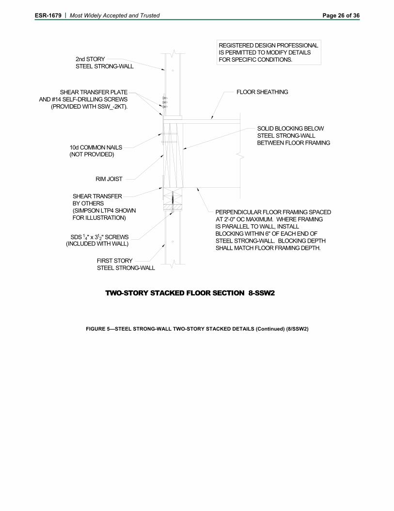
RIM JOIST
2nd STORYSTEEL STRONG-WALL
SHEAR TRANSFER PLATEAND #14 SELF-DRILLING SCREWS
(PROVIDED WITH SSW_-2KT).
SOLID BLOCKING BELOWSTEEL STRONG-WALLBETWEEN FLOOR FRAMING
FIRST STORYSTEEL STRONG-WALL
FLOOR SHEATHING
SHEAR TRANSFERBY OTHERS(SIMPSON LTP4 SHOWNFOR ILLUSTRATION)
PERPENDICULAR FLOOR FRAMING SPACEDAT 2'-0" OC MAXIMUM. WHERE FRAMINGIS PARALLEL TO WALL, INSTALLBLOCKING WITHIN 6" OF EACH END OFSTEEL STRONG-WALL. BLOCKING DEPTHSHALL MATCH FLOOR FRAMING DEPTH.
SDS 14" x 312" SCREWS
(INCLUDED WITH WALL)
10d COMMON NAILS(NOT PROVIDED)
TWO-STORY STACKED FLOOR SECTION 8-SSW2
REGISTERED DESIGN PROFESSIONALIS PERMITTED TO MODIFY DETAILS FOR SPECIFIC CONDITIONS.
FIGURE 5—STEEL STRONG-WALL TWO-STORY STACKED DETAILS (Continued) (8/SSW2)
ESR-1679 | Most Widely Accepted and Trusted Page 27 of 36
OR
SSW-STK OPTION(FACTORY INSTALLED)
BOTTOM WALL:ADD -STK TO MODELNAME.EXAMPLE: SSW24x8-STK
STANDARDSTEEL STRONG-WALLAT TOP WALL
SSW3
3
SSW3
5
SSW3
4
W
REGISTERED DESIGN PROFESSIONALIS PERMITTED TO MODIFY DETAILS FOR SPECIFIC CONDITIONS.
FULL HEIGHT STUDS (DESIGNBY OTHERS FOR OUT-OF-PLANEWIND OR SEISMIC LOADING). 2-2x6 MINIMUMEACH SIDE WITH 10d NAILS AT
AND STUD TO STUD.16" OC STUD TO SSW NAILER STUD
ALTERNATE
H
BALLOON FRAMING 1-SSW3
SSW3
2
FIGURE 6—STEEL STRONG-WALL BALLOON FRAMING DETAILS (1/SSW3)
ESR-1679 | Most Widely Accepted and Trusted Page 28 of 36
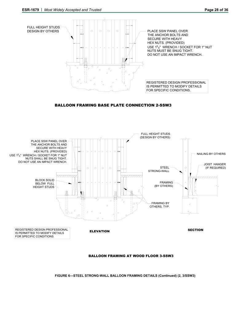
REGISTERED DESIGN PROFESSIONALIS PERMITTED TO MODIFY DETAILS FOR SPECIFIC CONDITIONS.
BALLOON FRAMING BASE PLATE CONNECTION 2-SSW3
PLACE SSW PANEL OVER THE ANCHOR BOLTS AND SECURE WITH HEAVY HEX NUTS. (PROVIDED) USE 15
8" WRENCH / SOCKET FOR 1" NUTNUTS MUST BE SNUG TIGHT.DO NOT USE AN IMPACT WRENCH.
FULL HEIGHT STUDSDESIGN BY OTHERS
FRAMING BYOTHERS, TYP.
FULL HEIGHT STUDS(DESIGN BY OTHERS)
BLOCK SOLIDBELOW FULL
HEIGHT STUDS
ELEVATION
BALLOON FRAMING AT WOOD FLOOR 3-SSW3
STEELSTRONG-WALL
FRAMING(BY OTHERS)
JOIST HANGER(IF REQUIRED)
NAILING BY OTHERS
SECTION
PLACE SSW PANEL OVER THE ANCHOR BOLTS AND
SECURE WITH HEAVY HEX NUTS. (PROVIDED)
USE 158" WRENCH / SOCKET FOR 1" NUT
NUTS SHALL BE SNUG TIGHT.DO NOT USE AN IMPACT WRENCH.
REGISTERED DESIGN PROFESSIONALIS PERMITTED TO MODIFY DETAILS FOR SPECIFIC CONDITIONS.
FIGURE 6—STEEL STRONG-WALL BALLOON FRAMING DETAILS (Continued) (2, 3/SSW3)
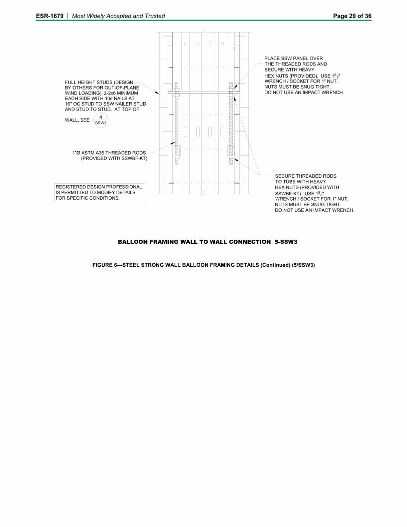
ESR-1679 | Most Widely Accepted and Trusted Page 29 of 36
FULL HEIGHT STUDS (DESIGNBY OTHERS FOR OUT-OF-PLANEWIND LOADING). 2-2x6 MINIMUMEACH SIDE WITH 10d NAILS AT
AND STUD TO STUD. AT TOP OF
1"Ø ASTM A36 THREADED RODS
WALL, SEE
16" OC STUD TO SSW NAILER STUD
PLACE SSW PANEL OVER THE THREADED RODS AND SECURE WITH HEAVY HEX NUTS (PROVIDED). USE 15
8" WRENCH / SOCKET FOR 1" NUT.NUTS MUST BE SNUG TIGHT.DO NOT USE AN IMPACT WRENCH.
SECURE THREADED RODSTO TUBE WITH HEAVYHEX NUTS (PROVIDED WITH SSWBF-KT). USE 15
8" WRENCH / SOCKET FOR 1" NUT.NUTS MUST BE SNUG TIGHT.DO NOT USE AN IMPACT WRENCH.
(PROVIDED WITH SSWBF-KT)
SSW3
4
BALLOON FRAMING WALL TO WALL CONNECTION 5-SSW3
REGISTERED DESIGN PROFESSIONALIS PERMITTED TO MODIFY DETAILS FOR SPECIFIC CONDITIONS.
FIGURE 6—STEEL STRONG WALL BALLOON FRAMING DETAILS (Continued) (5/SSW3)
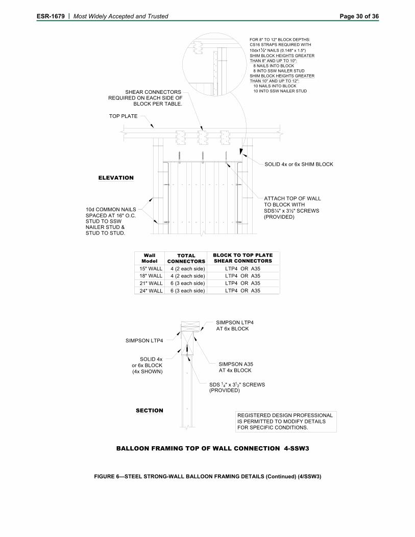
ESR-1679 | Most Widely Accepted and Trusted Page 30 of 36
TOP PLATE
SHEAR CONNECTORSREQUIRED ON EACH SIDE OF
BLOCK PER TABLE.
SOLID 4x or 6x SHIM BLOCK
STUD TO SSW
10d COMMON NAILS
NAILER STUD &STUD TO STUD.
TOTAL CONNECTORS
BLOCK TO TOP PLATESHEAR CONNECTORS
Wall Model
18" WALL
21" WALL
24" WALL
4 (2 each side)
6 (3 each side)
6 (3 each side)
15" WALL 4 (2 each side)
LTP4 OR A35
LTP4 OR A35
LTP4 OR A35
LTP4 OR A35
SIMPSON LTP4
SOLID 4xor 6x BLOCK(4x SHOWN)
SDS 14" x 312" SCREWS
(PROVIDED)
SIMPSON A35 AT 4x BLOCK
SIMPSON LTP4AT 6x BLOCK
ELEVATION
SECTION
ATTACH TOP OF WALLTO BLOCK WITHSDS¼" x 3½" SCREWS(PROVIDED)
FOR 8" TO 12" BLOCK DEPTHS:CS16 STRAPS REQUIRED WITH
10dx1½" NAILS (0.148" x 1.5")SHIM BLOCK HEIGHTS GREATERTHAN 8" AND UP TO 10": 8 NAILS INTO BLOCK 8 INTO SSW NAILER STUDSHIM BLOCK HEIGHTS GREATERTHAN 10" AND UP TO 12": 10 NAILS INTO BLOCK 10 INTO SSW NAILER STUD
BALLOON FRAMING TOP OF WALL CONNECTION 4-SSW3
SPACED AT 16" O.C.
REGISTERED DESIGN PROFESSIONALIS PERMITTED TO MODIFY DETAILS FOR SPECIFIC CONDITIONS.
FIGURE 6—STEEL STRONG-WALL BALLOON FRAMING DETAILS (Continued) (4/SSW3)
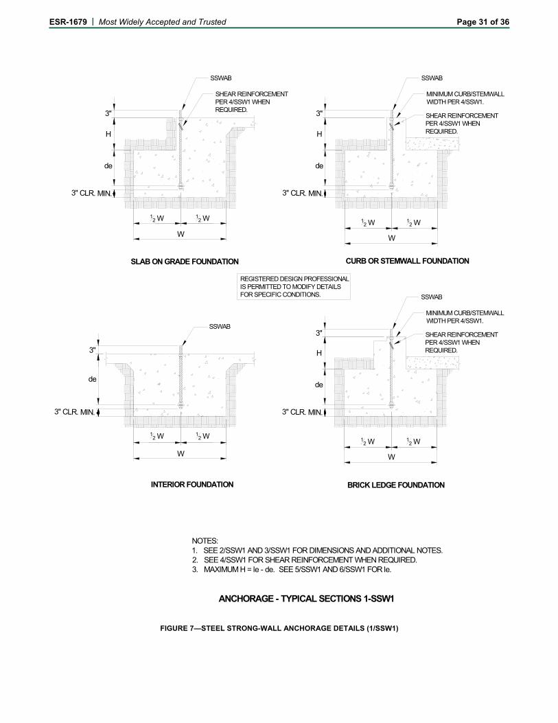
ESR-1679 | Most Widely Accepted and Trusted Page 31 of 36
CURB OR STEMWALL FOUNDATION SLAB ON GRADE FOUNDATION
W
3"
de
INTERIOR FOUNDATION
NOTES:1. SEE 2/SSW1 AND 3/SSW1 FOR DIMENSIONS AND ADDITIONAL NOTES.2. SEE 4/SSW1 FOR SHEAR REINFORCEMENT WHEN REQUIRED.3. MAXIMUM H = le - de. SEE 5/SSW1 AND 6/SSW1 FOR le.
H
3" CLR. MIN.
12 W 1
2 W
W
3"
de
H
3" CLR. MIN.
12 W 1
2 W
W
3"
de
H
3" CLR. MIN.
12 W 1
2 W
W
3"
de
3" CLR. MIN.
12 W 1
2 W
BRICK LEDGE FOUNDATION
ANCHORAGE - TYPICAL SECTIONS 1-SSW1
SSWAB
SHEAR REINFORCEMENT PER 4/SSW1 WHEN REQUIRED.
SSWAB
SHEAR REINFORCEMENT PER 4/SSW1 WHEN REQUIRED.
SSWAB
SHEAR REINFORCEMENT PER 4/SSW1 WHEN REQUIRED.
SSWAB
REGISTERED DESIGN PROFESSIONALIS PERMITTED TO MODIFY DETAILS FOR SPECIFIC CONDITIONS.
MINIMUM CURB/STEMWALL WIDTH PER 4/SSW1.
MINIMUM CURB/STEMWALL WIDTH PER 4/SSW1.
FIGURE 7—STEEL STRONG-WALL ANCHORAGE DETAILS (1/SSW1)
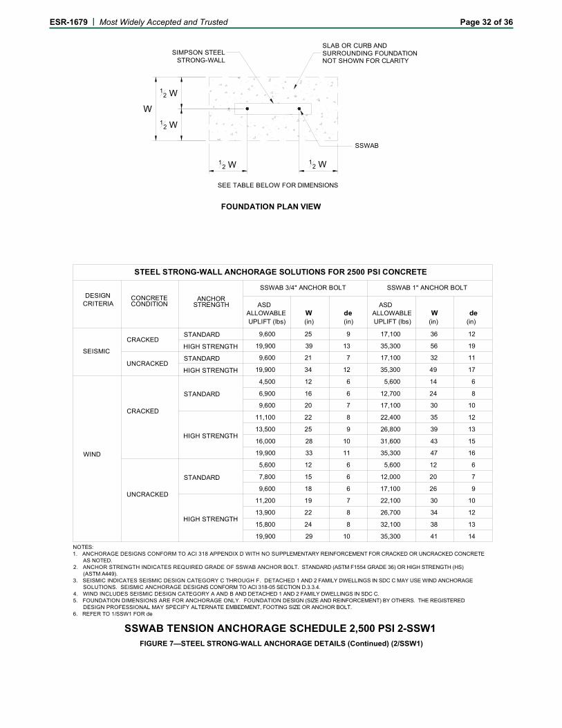
ESR-1679 | Most Widely Accepted and Trusted Page 32 of 36
SEE TABLE BELOW FOR DIMENSIONS
W
SLAB OR CURB ANDSURROUNDING FOUNDATIONNOT SHOWN FOR CLARITY
12 W 1
2 W
12 W
12 W
SIMPSON STEELSTRONG-WALL
FOUNDATION PLAN VIEW
SSWAB
STEEL STRONG-WALL ANCHORAGE SOLUTIONS FOR 2500 PSI CONCRETE
ASD ASDALLOWABLE W de ALLOWABLE W de UPLIFT (lbs) (in) (in) UPLIFT (lbs) (in) (in)
CONCRETE CONDITION
CRACKED
UNCRACKED
CRACKED
UNCRACKED
ANCHOR STRENGTH
STANDARD
HIGH STRENGTH
STANDARD
HIGH STRENGTH
STANDARD
HIGH STRENGTH
STANDARD
HIGH STRENGTH
DESIGNCRITERIA
SEISMIC
WIND
9,600 25 9
19,900 39 13
9,600 21 7
19,900 34 12
4,500 12 6
6,900 16 6
9,600 20 7
11,100 22 8
13,500 25 9
16,000 28 10
19,900 33 11
5,600 12 6
7,800 15 6
9,600 18 6
11,200 19 7
13,900 22 8
15,800 24 8
19,900 29 10
SSWAB 3/4" ANCHOR BOLT SSWAB 1" ANCHOR BOLT
17,100 36 12
35,300 56 19
17,100 32 11
35,300 49 17
5,600 14 6
12,700 24 8
17,100 30 10
22,400 35 12
26,800 39 13
31,600 43 15
35,300 47 16
5,600 12 6
12,000 20 7
17,100 26 9
22,100 30 10
26,700 34 12
32,100 38 13
35,300 41 14
NOTES:1. ANCHORAGE DESIGNS CONFORM TO ACI 318 APPENDIX D WITH NO SUPPLEMENTARY REINFORCEMENT FOR CRACKED OR UNCRACKED CONCRETE AS NOTED.2. ANCHOR STRENGTH INDICATES REQUIRED GRADE OF SSWAB ANCHOR BOLT. STANDARD (ASTM F1554 GRADE 36) OR HIGH STRENGTH (HS) (ASTM A449). 3. SEISMIC INDICATES SEISMIC DESIGN CATEGORY C THROUGH F. DETACHED 1 AND 2 FAMILY DWELLINGS IN SDC C MAY USE WIND ANCHORAGE SOLUTIONS. SEISMIC ANCHORAGE DESIGNS CONFORM TO ACI 318-05 SECTION D.3.3.4.4. WIND INCLUDES SEISMIC DESIGN CATEGORY A AND B AND DETACHED 1 AND 2 FAMILY DWELLINGS IN SDC C.5. FOUNDATION DIMENSIONS ARE FOR ANCHORAGE ONLY. FOUNDATION DESIGN (SIZE AND REINFORCEMENT) BY OTHERS. THE REGISTERED DESIGN PROFESSIONAL MAY SPECIFY ALTERNATE EMBEDMENT, FOOTING SIZE OR ANCHOR BOLT.6. REFER TO 1/SSW1 FOR de
SSWAB TENSION ANCHORAGE SCHEDULE 2,500 PSI 2-SSW1
FIGURE 7—STEEL STRONG-WALL ANCHORAGE DETAILS (Continued) (2/SSW1)
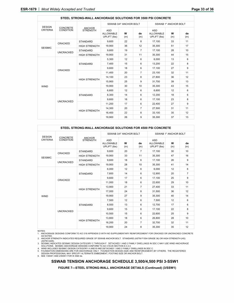
ESR-1679 | Most Widely Accepted and Trusted Page 33 of 36
STEEL STRONG-WALL ANCHORAGE SOLUTIONS FOR 3500 PSI CONCRETE
ASD ASDALLOWABLE W de ALLOWABLE W de UPLIFT (lbs) (in) (in) UPLIFT (lbs) (in) (in)
CONCRETE CONDITION
CRACKED
UNCRACKED
CRACKED
UNCRACKED
ANCHOR STRENGTH
STANDARD
HIGH STRENGTH
STANDARD
HIGH STRENGTH
STANDARD
HIGH STRENGTH
STANDARD
HIGH STRENGTH
DESIGNCRITERIA
SEISMIC
WIND
9,600 22 8
19,900 36 12
9,600 19 7
19,900 31 11
5,300 12 6
7,400 15 6
9,600 18 6
11,400 20 7
14,100 23 8
15,900 25 9
19,900 30 10
6,600 12 6
8,300 14 6
9,600 16 6
11,200 17 6
14,300 20 7
16,400 22 8
19,900 26 9
SSWAB 3/4" ANCHOR BOLT SSWAB 1" ANCHOR BOLT
17,100 33 11
35,300 51 17
17,100 28 10
35,300 44 15
6,000 13 6
13,200 22 8
17,100 27 9
23,100 32 11
27,800 36 12
31,700 39 13
35,300 43 15
6,600 12 6
12,200 18 6
17,100 23 8
22,400 27 9
27,500 31 11
33,100 35 12
35,300 37 13
STEEL STRONG-WALL ANCHORAGE SOLUTIONS FOR 4500 PSI CONCRETE
ASD ASDALLOWABLE W de ALLOWABLE W de UPLIFT (lbs) (in) (in) UPLIFT (lbs) (in) (in)
CONCRETE CONDITION
CRACKED
UNCRACKED
CRACKED
UNCRACKED
ANCHOR STRENGTH
STANDARD
HIGH STRENGTH
STANDARD
HIGH STRENGTH
STANDARD
HIGH STRENGTH
STANDARD
HIGH STRENGTH
DESIGNCRITERIA
SEISMIC
WIND
SSWAB 3/4" ANCHOR BOLT SSWAB 1" ANCHOR BOLT
17,100 30 10
35,300 47 16
17,100 26 9
35,300 41 14
6,000 12 6
12,900 20 7
17,100 25 9
22,600 29 10
27,400 33 11
31,500 36 12
35,300 40 14
7,500 12 6
12,700 17 6
17,100 22 8
22,600 25 9
26,800 28 10
32,700 32 11
35,300 35 12
SSWAB TENSION ANCHORAGE SCHEDULE 3,500/4,500 PSI 3-SSW1
NOTES:1. ANCHORAGE DESIGNS CONFORM TO ACI 318 APPENDIX D WITH NO SUPPLEMENTARY REINFORCEMENT FOR CRACKED OR UNCRACKED CONCRETE AS NOTED.2. ANCHOR STRENGTH INDICATES REQUIRED GRADE OF SSWAB ANCHOR BOLT. STANDARD (ASTM F1554 GRADE 36) OR HIGH STRENGTH (HS) (ASTM A449). 3. SEISMIC INDICATES SEISMIC DESIGN CATEGORY C THROUGH F. DETACHED 1 AND 2 FAMILY DWELLINGS IN SDC C MAY USE WIND ANCHORAGE SOLUTIONS. SEISMIC ANCHORAGE DESIGNS CONFORM TO ACI 318-05 SECTION D.3.3.4.4. WIND INCLUDES SEISMIC DESIGN CATEGORY A AND B AND DETACHED 1 AND 2 FAMILY DWELLINGS IN SDC C.5. FOUNDATION DIMENSIONS ARE FOR ANCHORAGE ONLY. FOUNDATION DESIGN (SIZE AND REINFORCEMENT) BY OTHERS. THE REGISTERED DESIGN PROFESSIONAL MAY SPECIFY ALTERNATE EMBEDMENT, FOOTING SIZE OR ANCHOR BOLT.6. SEE 1/SSW1 AND 2/SSW1 FOR W AND de.
9,600 20 7
19,900 33 11
9,600 18 6
19,900 28 10
6,000 12 6
7,600 14 6
9,600 17 6
11,000 18 6
13,900 21 7
17,000 24 8
19,900 27 9
7,500 12 6
8,500 13 6
9,600 15 6
10,500 15 6
13,800 18 6
16,200 20 7
19,900 24 8
FIGURE 7—STEEL STRONG-WALL ANCHORAGE DETAILS (Continued) (3/SSW1)
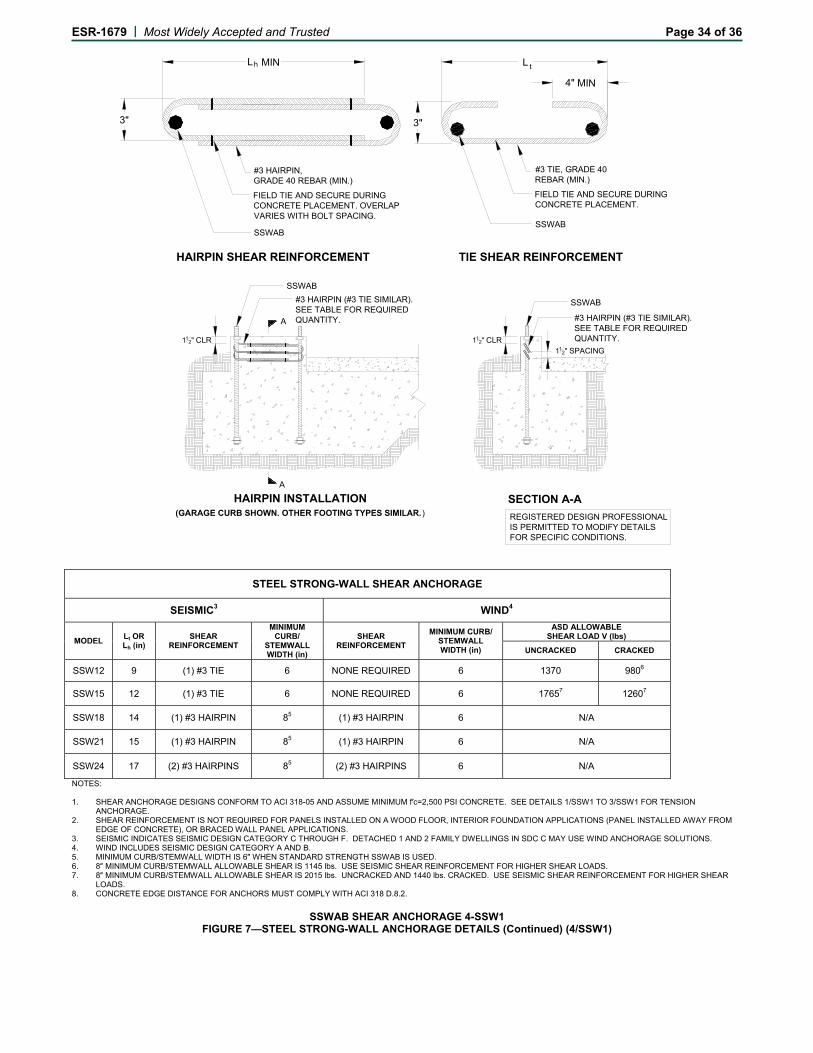
ESR-1679 | Most Widely Accepted and Trusted Page 34 of 36
HAIRPIN INSTALLATION(GARAGE CURB SHOWN. OTHER FOOTING TYPES SIMILAR.)
SSWAB
#3 HAIRPIN (#3 TIE SIMILAR). SEE TABLE FOR REQUIRED QUANTITY.
SECTION A-A
SSWAB
#3 HAIRPIN (#3 TIE SIMILAR).SEE TABLE FOR REQUIRED QUANTITY.
A
A
4" MIN
3"
L L MIN
3"
FIELD TIE AND SECURE DURING CONCRETE PLACEMENT. OVERLAP VARIES WITH BOLT SPACING.
#3 HAIRPIN, GRADE 40 REBAR (MIN.)
SSWAB
HAIRPIN SHEAR REINFORCEMENT TIE SHEAR REINFORCEMENT
112" CLR 11
2" CLR11
2" SPACING
h t
REGISTERED DESIGN PROFESSIONALIS PERMITTED TO MODIFY DETAILS FOR SPECIFIC CONDITIONS.
FIELD TIE AND SECURE DURING CONCRETE PLACEMENT.
#3 TIE, GRADE 40 REBAR (MIN.)
SSWAB
STEEL STRONG-WALL SHEAR ANCHORAGE
SEISMIC3 WIND4
MODEL Lt OR Lh (in)
SHEAR REINFORCEMENT
MINIMUM CURB/
STEMWALL WIDTH (in)
SHEAR REINFORCEMENT
MINIMUM CURB/ STEMWALL WIDTH (in)
ASD ALLOWABLE SHEAR LOAD V (lbs)
UNCRACKED CRACKED
SSW12 9 (1) #3 TIE 6 NONE REQUIRED 6 1370 9806
SSW15 12 (1) #3 TIE 6 NONE REQUIRED 6 17657 12607
SSW18 14 (1) #3 HAIRPIN 85 (1) #3 HAIRPIN 6 N/A
SSW21 15 (1) #3 HAIRPIN 85 (1) #3 HAIRPIN 6 N/A
SSW24 17 (2) #3 HAIRPINS 85 (2) #3 HAIRPINS 6 N/A
NOTES: 1. SHEAR ANCHORAGE DESIGNS CONFORM TO ACI 318-05 AND ASSUME MINIMUM f′c=2,500 PSI CONCRETE. SEE DETAILS 1/SSW1 TO 3/SSW1 FOR TENSION
ANCHORAGE. 2. SHEAR REINFORCEMENT IS NOT REQUIRED FOR PANELS INSTALLED ON A WOOD FLOOR, INTERIOR FOUNDATION APPLICATIONS (PANEL INSTALLED AWAY FROM
EDGE OF CONCRETE), OR BRACED WALL PANEL APPLICATIONS. 3. SEISMIC INDICATES SEISMIC DESIGN CATEGORY C THROUGH F. DETACHED 1 AND 2 FAMILY DWELLINGS IN SDC C MAY USE WIND ANCHORAGE SOLUTIONS. 4. WIND INCLUDES SEISMIC DESIGN CATEGORY A AND B. 5. MINIMUM CURB/STEMWALL WIDTH IS 6″ WHEN STANDARD STRENGTH SSWAB IS USED. 6. 8″ MINIMUM CURB/STEMWALL ALLOWABLE SHEAR IS 1145 lbs. USE SEISMIC SHEAR REINFORCEMENT FOR HIGHER SHEAR LOADS. 7. 8″ MINIMUM CURB/STEMWALL ALLOWABLE SHEAR IS 2015 lbs. UNCRACKED AND 1440 lbs. CRACKED. USE SEISMIC SHEAR REINFORCEMENT FOR HIGHER SHEAR
LOADS. 8. CONCRETE EDGE DISTANCE FOR ANCHORS MUST COMPLY WITH ACI 318 D.8.2.
SSWAB SHEAR ANCHORAGE 4-SSW1
FIGURE 7—STEEL STRONG-WALL ANCHORAGE DETAILS (Continued) (4/SSW1)
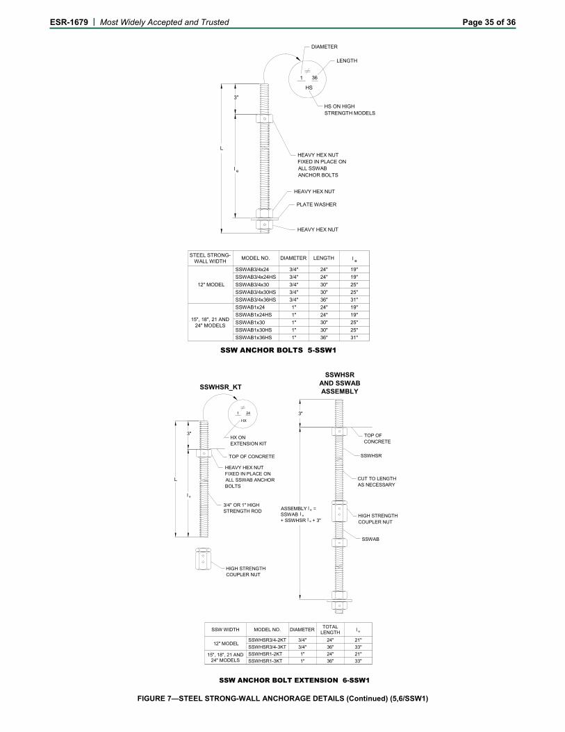
ESR-1679 | Most Widely Accepted and Trusted Page 35 of 36
MODEL NO.STEEL STRONG-
WALL WIDTH
12" MODEL SSWAB3/4x24
SSWAB3/4x24HS
SSWAB3/4x30
SSWAB3/4x30HS
SSWAB3/4x36HS
DIAMETER LENGTH
3/4" 24" 19"
3/4" 24" 19"
3/4" 30" 25"
3/4" 30" 25"
3/4" 36" 31"
SSWAB1x24
SSWAB1x24HS
SSWAB1x30
SSWAB1x30HS
SSWAB1x36HS
1" 24" 19"
1" 24" 19"
1" 30" 25"
1" 30" 25"
1" 36" 31"
15", 18", 21 AND24" MODELS
36
HEAVY HEX NUT
HEAVY HEX NUTFIXED IN PLACE ONALL SSWAB ANCHOR BOLTS
HS
HS ON HIGHSTRENGTH MODELS
1
LENGTH
DIAMETER
HEAVY HEX NUT
PLATE WASHER
SSW ANCHOR BOLTS 5-SSW1
l e
L
3"
l e
SSW ANCHOR BOLT EXTENSION 6-SSW1
l e
L
3"
3"
ASSEMBLY =SSWAB + SSWHSR + 3"
l e
l e
l e
l e
MODEL NO.TOTAL
LENGTH
12" MODELSSWHSR3/4-2KT
SSWHSR3/4-3KT
DIAMETER
3/4" 24" 21"
3/4" 36" 33"
SSWHSR1-2KT
SSWHSR1-3KT
1" 24" 21"
1" 36" 33"15", 18", 21 AND
24" MODELS
SSW WIDTH
24
3/4" OR 1" HIGHSTRENGTH ROD
HEAVY HEX NUTFIXED IN PLACE ONALL SSWAB ANCHORBOLTS
HX
HX ONEXTENSION KIT
TOP OF CONCRETE
SSWHSR
HIGH STRENGTH COUPLER NUT
SSWAB
CUT TO LENGTH AS NECESSARY
SSWHSRAND SSWABASSEMBLY
1
SSWHSR_KT
HIGH STRENGTH COUPLER NUT
TOP OF CONCRETE
FIGURE 7—STEEL STRONG-WALL ANCHORAGE DETAILS (Continued) (5,6/SSW1)
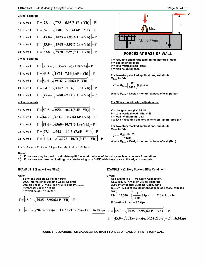
ESR-1679 | Most Widely Accepted and Trusted Page 36 of 36
2.5 ksi concrete
12 in. wall [ ] PVh)5.95(3.4P78828.1T −+−−=
15 in. wall [ ] PVh)5.95(4.6P130136.1T −+−−=
18 in. wall [ ] PVh)5.95(6.1P202545.0T −+−−=
21 in. wall [ ] PVh)5.95(7.6P290853.9T −+−−=
24 in. wall [ ] PVh)5.95(9.1P395062.8T −+−−=
3.0 ksi concrete T = resulting anchorage tension (uplift) force (kips) V = design shear (kips) P = total vertical load (kips) h = wall height (inches) For two-story stacked applications, substitute MBase for Vh:
Where MBase = Design moment at base of wall (ft-lbs)
12 in. wall [ ] PVh)7.14(3.4P113533.7T −+−−=
15 in. wall [ ] PVh)7.14(4.6P187443.3T −+−−=
18 in. wall [ ] PVh)7.14(6.1P291654.0T −+−−=
21 in. wall [ ] PVh)7.14(7.6P418764.7T −+−−=
24 in. wall [ ] PVh)7.14(9.1P568875.4T −+−−=
4.5 ksi concrete For SI use the following adjustments:
12 in. wall [ ] PVh)10.71(3.4P255450.5T −+−−= V = design shear (kN) / 4.45 P = total vertical load (kN) / 4.45 h = wall height (mm) / 25.4 T x 4.45 = resulting anchorage tension (uplift) force (kN) For two-story stacked applications, substitute MBase for Vh:
Where MBase = Design moment at base of wall (N-m)
15 in. wall [ ] PVh)10.71(4.6P421664.9T −+−−=
18 in. wall [ ] PVh)10.71(6.1P656081.0T −+−−=
21 in. wall [ ] PVh)10.71(7.6P942197.1T −+−−=
24 in. wall [ ] PVh)10.71(9.1P12,797113.1T −+−−=
For SI: 1 inch = 25.4 mm, 1 kip = 4.45 kN, 1 ft-lb = 1.36 N-m Notes: 1.) Equations may be used to calculate uplift forces at the base of first-story walls on concrete foundations. 2.) Equations are based on limiting concrete bearing on a 3-1/2” wide base plate at the edge of concrete.
EXAMPLE 3 (Single-Story SSW): Given:
SSW18x9 wall on 2.5 ksi concrete 2006 International Building Code, Seismic Design Shear (V) = 2.0 kips < 2.15 kips (VAllowable) P (Vertical Load) = 1.0 kip h = wall height = 105.25”
[ ] PVh)5.95(6.1P202545.0T −+−−=
[ ] kips 16.91.0105.25)2.015.95(6.1202545.0T =−×+×−−=
EXAMPLE 4 (2-Story Stacked SSW Condition): Given:
See Example 2 – Two Story Application. SSW18x9-STK wall on 2.5 ksi concrete 2006 International Building Code, Wind MBase = 17,550 ft-lbs (Moment at base of 2-story, stacked wall)
P (Vertical Load) = 2.0 kips
[ ] PVh)5.95(6.1P202545.0T −+−−=
[ ] kips 16.62210.6)25.95(6.1202545.0T =−+×−−=
FIGURE 8—EQUATIONS FOR CALCULATING UPLIFT FORCES AT BASE OF FIRST-STORY WALL
in)-(kip1000
12MVh Base
=
0113
m)-(N MVh Base
.=
in-kip 210.6in-kip1000
1217,550Vh =
×=
Related Documents