Series Ergonomic Ergonomic 320.250 GH Operating instructions Before transporting and using the machine, please read the instructions thoroughly! Seriové číslo / Serien Nummer / Serial Number ___________________

Welcome message from author
This document is posted to help you gain knowledge. Please leave a comment to let me know what you think about it! Share it to your friends and learn new things together.
Transcript

Series Ergonomic
Ergonomic 320.250 GH
Operating instructions
Before transporting and using the machine, please read the instructions thoroughly!
Seriové číslo / Serien Nummer / Serial Number ___________________
2 Manual version: 1.04 / Mar. 2010Manual rev.: 1
Service and information
Your BOMAR dealer:
Direct BOMAR contact:
BOMAR spol. s r.o. Těžební 1236/1 62700 Brno Czech Republic, EU
telefon: +420 – 533 426 100 fax: +420 – 533 426 109 e-mail: [email protected] www: http://www.bomar.cz
We are available:
Mondays to Fridays 700 – 1600
Version:
1.04 / Mar. 2010
rev. 1
BOMAR, spol. s r.o. © – Subject to modifications and amendments.

3

4 Manual version: 1.04 / Mar. 2010Manual rev.: 1
5
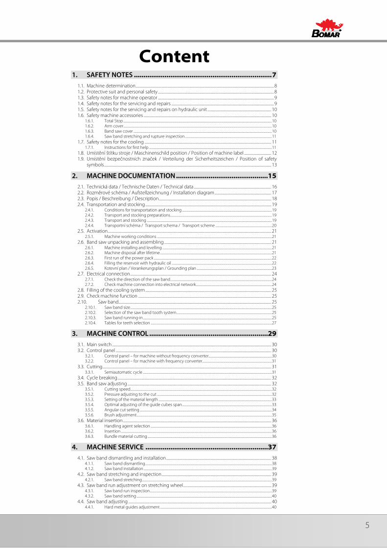
Content 1. SAFETY NOTES ........................................................................ 7
1.1. Machine determination .......................................................................................................................................................... 8 1.2. Protective suit and personal safety ................................................................................................................................. 8 1.3. Safety notes for machine operator ................................................................................................................................. 9 1.4. Safety notes for the servicing and repairs .................................................................................................................. 9 1.5. Safety notes for the servicing and repairs on hydraulic unit ....................................................................... 10 1.6. Safety machine accessories .............................................................................................................................................. 10
1.6.1. Total Stop .............................................................................................................................................................................................. 10 1.6.2. Arm cover .............................................................................................................................................................................................. 10 1.6.3. Band saw cover ................................................................................................................................................................................. 10 1.6.4. Saw band stretching and rupture inspection ............................................................................................................... 11
1.7. Safety notes for the cooling ............................................................................................................................................. 11 1.7.1. Instructions for first help ............................................................................................................................................................. 11
1.8. Umístění štítku stroje / Maschinenschild position / Position of machine label .............................. 12 1.9. Umístění bezpečnostních značek / Verteilung der Sicherheitszeichen / Position of safety
symbols .......................................................................................................................................................................................... 13
2. MACHINE DOCUMENTATION ................................................15 2.1. Technická data / Technische Daten / Technical data ...................................................................................... 16 2.2. Rozměrové schéma / Aufstellzeichnung / Installation diagram ............................................................... 17 2.3. Popis / Beschreibung / Description ............................................................................................................................. 18 2.4. Transportation and stocking ............................................................................................................................................ 19
2.4.1. Conditions for transportation and stocking ................................................................................................................... 19 2.4.2. Transport and stocking preparations .................................................................................................................................. 19 2.4.3. Transport and stocking ................................................................................................................................................................ 19 2.4.4. Transportní schéma / Transport schema / Transport scheme ........................................................................ 20
2.5. Activation...................................................................................................................................................................................... 21 2.5.1. Machine working conditions ................................................................................................................................................... 21
2.6. Band saw unpacking and assembling ....................................................................................................................... 21 2.6.1. Machine installing and levelling ............................................................................................................................................ 21 2.6.2. Machine disposal after lifetime ............................................................................................................................................... 21 2.6.3. First run of the power pack ....................................................................................................................................................... 22 2.6.4. Filling the reservoir with hydraulic oil ................................................................................................................................ 22 2.6.5. Kotevní plan / Verankerungsplan / Grounding plan ................................................................................................ 23
2.7. Electrical connection ............................................................................................................................................................. 24 2.7.1. Check the direction of the saw band .................................................................................................................................. 24 2.7.2. Check machine connection into electrical network ................................................................................................. 24
2.8. Filling of the cooling system ............................................................................................................................................ 25 2.9. Check machine function .................................................................................................................................................... 25 2.10. Saw band.......................................................................................................................................................................... 25
2.10.1. Saw band size ..................................................................................................................................................................................... 25 2.10.2. Selection of the saw band tooth system .......................................................................................................................... 25 2.10.3. Saw band running-in ..................................................................................................................................................................... 25 2.10.4. Tables for teeth selection ........................................................................................................................................................... 27
3. MACHINE CONTROL ..............................................................29 3.1. Main switch ................................................................................................................................................................................. 30 3.2. Control panel ............................................................................................................................................................................. 30
3.2.1. Control panel – for machine without frequency converter................................................................................. 30 3.2.2. Control panel – for machine with frequency converter......................................................................................... 31
3.3. Cutting............................................................................................................................................................................................ 31 3.3.1. Semiautomatic cycle ..................................................................................................................................................................... 31
3.4. Cycle breaking ........................................................................................................................................................................... 32 3.5. Band saw adjusting ................................................................................................................................................................ 32
3.5.1. Cutting speed ..................................................................................................................................................................................... 32 3.5.2. Pressure adjusting to the cut ................................................................................................................................................... 32 3.5.3. Setting of the material length ................................................................................................................................................. 33 3.5.4. Optimal adjusting of the guide cubes span ................................................................................................................... 33 3.5.5. Angular cut setting ......................................................................................................................................................................... 34 3.5.6. Brush adjustment ............................................................................................................................................................................. 35
3.6. Material insertion ..................................................................................................................................................................... 36 3.6.1. Handling agent selection ........................................................................................................................................................... 36 3.6.2. Insertion ................................................................................................................................................................................................. 36 3.6.3. Bundle material cutting ............................................................................................................................................................... 36
4. MACHINE SERVICE ................................................................37 4.1. Saw band dismantling and installation ..................................................................................................................... 38
4.1.1. Saw band dismantling .................................................................................................................................................................. 38 4.1.2. Saw band installation .................................................................................................................................................................... 39
4.2. Saw band stretching and inspection .......................................................................................................................... 39 4.2.1. Saw band stretching ...................................................................................................................................................................... 39
4.3. Saw band run adjustment on stretching wheel .................................................................................................. 39 4.3.1. Saw band run inspection ............................................................................................................................................................ 39 4.3.2. Saw band setting ............................................................................................................................................................................. 40
4.4. Saw band adjusting ............................................................................................................................................................... 40 4.4.1. Hard metal guides adjustment ............................................................................................................................................... 40
6 Manual version: 1.04 / Mar. 2010Manual rev.: 1
4.4.2. Guide cube adjustment .............................................................................................................................................................. 41 4.4.3. Adjusting the limit switch of the saw band stretching .......................................................................................... 41 4.4.4. Angular stops adjustments ....................................................................................................................................................... 41 4.4.5. Adjusting of the turning console securing lever ........................................................................................................ 42 4.4.6. Saw frame lower position stop adjustment ................................................................................................................... 43 4.4.7. Adjustment of the limit switch of saw frame lower stop point ........................................................................ 43 4.4.8. Adjustment of the regulating pressure to the cut .................................................................................................... 44 4.4.9. Adjustment of a throttle valve ................................................................................................................................................ 45 4.4.10. Brush adjustment ............................................................................................................................................................................ 45
4.5. Cooling agents and chips disposal .............................................................................................................................. 46 4.5.1. Coolant device inspection......................................................................................................................................................... 46 4.5.2. Chips disposal .................................................................................................................................................................................... 46
4.6. Hydraulic, greases and oils ................................................................................................................................................ 47 4.6.1. Gearbox oils ........................................................................................................................................................................................ 47 4.6.2. Lubricant greases ............................................................................................................................................................................ 47 4.6.3. Lubrication ........................................................................................................................................................................................... 48 4.6.4. Hydraulic oils ...................................................................................................................................................................................... 48 4.6.5. Hydraulic unit service ................................................................................................................................................................... 49
4.7. Machine cleaning .................................................................................................................................................................... 49 4.8. Worn pieces replacement ................................................................................................................................................. 50
4.8.1. Hard metal guides replacement............................................................................................................................................ 50 4.8.2. Saw band guiding rollers replacement ............................................................................................................................ 50 4.8.3. Round brush replacement ........................................................................................................................................................ 52 4.8.4. Stretching wheel replacement ............................................................................................................................................... 53 4.8.5. Driving wheel replacement ...................................................................................................................................................... 55 4.8.6. Cooling pump replacement .................................................................................................................................................... 56
5. ZÁVADY / TROUBLESHOOTING ............................................ 59 5.1. Mechanical problems ........................................................................................................................................................... 60 5.2. Electric problems ..................................................................................................................................................................... 62 5.3. Hydraulic problems ................................................................................................................................................................ 63
6. SCHÉMATA / SCHEMAS / SCHEMATICS .............................. 65 6.1. Elektrická schémata / Elektroschemas / Wiring diagrams – bez frekv. měniče / ohne
Frequenzumrichter / without frequency convertor – 3×400 V/50 Hz, TN-C-S ................................ 66 6.2. Elektrické schema /Elektroschema /Wiring diagrams – frekv. měnič / Frequenzumrichter /
Frequency convertor – 3×400 V/50 Hz, TN-C-S ................................................................................................... 71 6.3. Hydraulické schéma / Hydraulikschema Hydraulic diagrams ................................................................... 76
7. VÝKRESY SESTAV PRO OBJEDNÁNÍ NÁHRADNÍCH DÍLŮ / ZEICHNUNGEN FÜR BESTELLUNG DER ERSATZTEILE / DRAWING ASSEMBLIES FOR SPARE PARTS ORDER ....................................... 79
7.1. Ergonomic 320.250 GH ........................................................................................................................................................ 80 7.2. Kusovník / Stückliste / Piece list – Ergonomic 320.250 GH ......................................................................... 81 7.3. Rameno / Sägerahmen / Saw arm ............................................................................................................................... 82 7.4. Kusovník / Stückliste / Piece list – Rameno / Sägerahmen / Saw arm ................................................. 83 7.5. Rameno / Sägerahmen / Saw arm ............................................................................................................................... 84 7.6. Kusovník / Stückliste / Piece list – Rameno / Sägerahmen / Saw arm ................................................. 85 7.7. Konzola / Konzole / Console ............................................................................................................................................ 86 7.8. Kusovník / Stückliste / Piece list – Konzola / Konzole / Console .............................................................. 87 7.9. Svěrák / Schraubstock / Vice ............................................................................................................................................ 88 7.10. Kusovník / Stückliste / Piece list – Svěrák / Schraubstock / Vice ................................................. 89 7.11. Napínání / Spannung / Tensioning ................................................................................................................. 90 7.12. Kusovník / Stückliste / Piece list – Napínání / Spannung / Tensioning .................................. 91 7.13. Vedení pásu / Sägebandführung / Belt guide ......................................................................................... 92 7.14. Kusovník / Stückliste / Piece list – Vedení pásu / Sägebandführung / Belt guide ........... 93 7.15. Vodící kostka / Führungsklotz / Guiding cube ......................................................................................... 94 7.16. Kusovník / Stückliste / Piece list – Vodící kostka / Führungsklotz / Guiding cube .......... 95 7.17. Vodící kostka / Führungsklotz / Guiding cube ......................................................................................... 96 7.18. Kusovník / Stückliste / Piece list – Vodící kostka / Führungsklotz / Guiding cube .......... 97 7.19. Válec zvedací / Hebezylinder / Lifting cylinder ....................................................................................... 98 7.20. Kusovník / Stückliste / Piece list – Válec zvedací / Hebezylinder / Lifting cylinder ......... 99 7.21. Podstavec / Untersatz / Base ............................................................................................................................. 100 7.22. Kusovník / Stückliste / Piece list – Podstavec / Untersatz / Base ............................................... 101 7.23. Doraz / Anschlag / Lenght Stop ...................................................................................................................... 102 7.24. Kusovník / Stückliste / Piece list – Doraz / Anschlag / Lenght Stop ....................................... 103 7.25. Chlazení / Kuhlung / Cooling ............................................................................................................................ 104 7.26. Kusovník / Stückliste / Piece list – Chlazení / Kuhlung / Cooling ............................................. 105 7.27. Válec / Zylinder / Roller ......................................................................................................................................... 106 7.28. Kartáč / Bürste / Brush ........................................................................................................................................... 107
7
Bezpečnostní pokyny Sicherheitshinw
eise Safety notes
1. Safety notes
8 Manual version: 1.04 / Mar. 2010Manual rev.: 1
Bezp
ečno
stní
pok
yny
Sich
erhe
itshi
nwei
se
Safe
ty n
otes
The operating instructions must be read by the person, who keeps in touch with the machine before transportation, installation, using, servicing, reparation, stocking or removal!
The operating instructions include relevant information. The operator must familiarise himself with the install and operation, safety notes and machine servicing, because reliability and service life must be reached. The operating instructions must avoid risks, which are linked to work on the machine. Before transporting and using of the machine, please read the instructions thoroughly!
1.1. Machine determination
The band saws Ergonomic 320.250 GH and Ergonomic 320.250 GH-F is determined for cutting and shortening of rolled bars and drawn bars and profiles from steels, stainless steels, non-ferrous metals and plastics with cutting angles from 0° to 60°.
Combustible materials are excepted for cutting! Any other usage and operation outside this range are unauthorized and the manufacturer/supplier does not accept any responsibility for any damages resulting from such misuse. The operator has full responsibility!
The machine is equipped with safety and protective guarding for operator and machine protection. Nevertheless, this safety and protective guarding cannot prevent injury. Service personnel must read this chapter and comprehend it, before he starts to work on the machine. Always keep instructions about work safety! Service personnel must take into account other aspects of the risk, which refer to the ambient conditions and the material.
1.2. Protective suit and personal safety
Wear tight fitting overalls! Loose fitting clothes may be caught with machine parts and cause serious injury.
Wear protective gloves! Material cuts and saw band have sharp edges and may cause serious injuries.
Wear protective shoes with non-skid soles! The unsuitable shoes may cause balance loss and following injury. Falling work pieces may cause serious injuries too.
Wear protective goggles! Chips and cooling liquid may damage your eyes.
Always wear ear protections! Most of the machines emit up to 80 dB and may damage your hearing.
Do not wear jewellery and always tie back long hair! Moving machine parts can catch jewellery or loose hair and may cause serious injuries.
Operate the machine only when you are fit enough to work. Illnesses or injuries diminish concentration. Avoid machine work, which may compromise the safety of you and your colleagues!
Attention! The operating instructions must be available at the machine! Keep the operating instructions in good condition!
Attention! Gloves you can use only at working material replacement (saw band)! The machine and accessories must be inactive! I f the machine is running, you must not wear gloves! It is dangerous, because some parts of the machine can catch gloves!
Attention! Consider the safety signs on the machine. Do not remove or damage them!

9
Bezpečnostní pokyny Sicherheitshinw
eise Safety notes
1.3. Safety notes for machine operator
Machine can be operated only by one person. Machine operator is responsible for presence of other persons by the machine.
Close covers before the machine starting and check, if the covers are not damaged. Damaged covers must be repaired or changed. Do not start the machine, if the cover is removed! Check, if the electric cables are not damaged.
• Do not hold the material for clamping to the vice and for cutting!
• Do not operate with the buttons and the switches on the control panel, when you have gloves!
• For machine starting take care, that there is nobody in the working area of the machine (it means in the working area of the vice, the saw band, the saw arm etc.).
• In no circumstances touch the rotating elements.
• Work on the machine only when the machine is in good condition!
• Check at least once in a shift, if the machine is not damaged. If the machine is damaged, you must bring the machine in order and you must inform your superior!
• Keep your working area clean! Ensure sufficient lighting in the working area.
• Take off the spilt water or the oil from the floor and dry it. Do not touch the cooling liquid with bare hands! Do not set the nozzle of the cooling liquid, when the machine is started on
• Do not remove the chips from the working area of the machine, when the machine is started on!
• Do not use the compressed air for the machine cleaning or for the chips removing!
• Use the protective instruments for chips removal!
1.4. Safety notes for the servicing and repairs
Switch off the main switch and lock it, before you start service work! Otherwise, there is possibility of hazardous machine starting.
Only qualified person can do the servicing and repairs. For parts changing, use only parts, which are identical with the originals. Otherwise, there is possibility of health hazard. Use only recommended type of the hydraulic oils and oils and lubricants!
Attention! Machine can be operated by person older than 18 years! Machine can be operated only person physically and mentally f it for this activity
Keep instructions and orders about work safety! Read the operating instructions, before you start to work on the machine! Keep the operating instructions in good condition!
Attention! Do not connect the machine to electricity if the covers are removed. Do not touch the electrical equipment.
Attention! Only a qualif ied professional can carry out the servicing and repairs of the electric equipment! Take special care during the work with electrical equipment. High voltage shock can have fatal consequences! Always keep notes about work safety! Otherwise, there is possibil ity of heavy injury!
10 Manual version: 1.04 / Mar. 2010Manual rev.: 1
Bezp
ečno
stní
pok
yny
Sich
erhe
itshi
nwei
se
Safe
ty n
otes
Do not remove or do not lock the limit switches or safety equipments! Any use of the saw, accessories or machine parts other than that intended by the BOMAR, spol. s r.o. company is not permitted. The guarantee on this product will be afterward lost and BOMAR, spol. s r.o. takes no responsibility for caused damages.
1.5. Safety notes for the servicing and repairs on hydraulic unit
Compliance with the the principles of cleanliness is basic requirement for trouble-free operation of hydraulic equipment. Hydraulic components are products made with high accuracy, and any contamination leads to a reduction lifetime or even malfunction. The consequences are very difficult to remove and expensive.
Always use clean tools. Parts and fasteners, which are part of a hydraulic circuit, never put away the dirty surface. The best cleaning agent is crepe paper, because the fibers of the cleaning cloths can also cause malfunction.
Protective cap from the threaded chamber remove just before the assembly of the unit.
Hoses and pipes before mounting flush with gasoline or other cleaning agent and blow compressed air.
All fittings must be properly tightened. However, do not raw power.
1.6. Safety machine accessories
The machine is equipped with safety accessories. It protects the operator from injuries and the machine before damage. The safety accessories are blocking accessories, emergency switches and covers. Check once in a week the function of the safety accessories. If the safety accessories are functionless, you must stop work and repair or change the safety accessories.
1.6.1. Total Stop
TOTAL STOP button is for emergency switch–off the machine in case defect or health hazard. By pressing TOTAL STOP button is interrupted the supply of the electrical power.
If any damages or fault appears, immediately press TOTAL STOP button! Release the pressing button is possible by twisting of the upper part of the button.
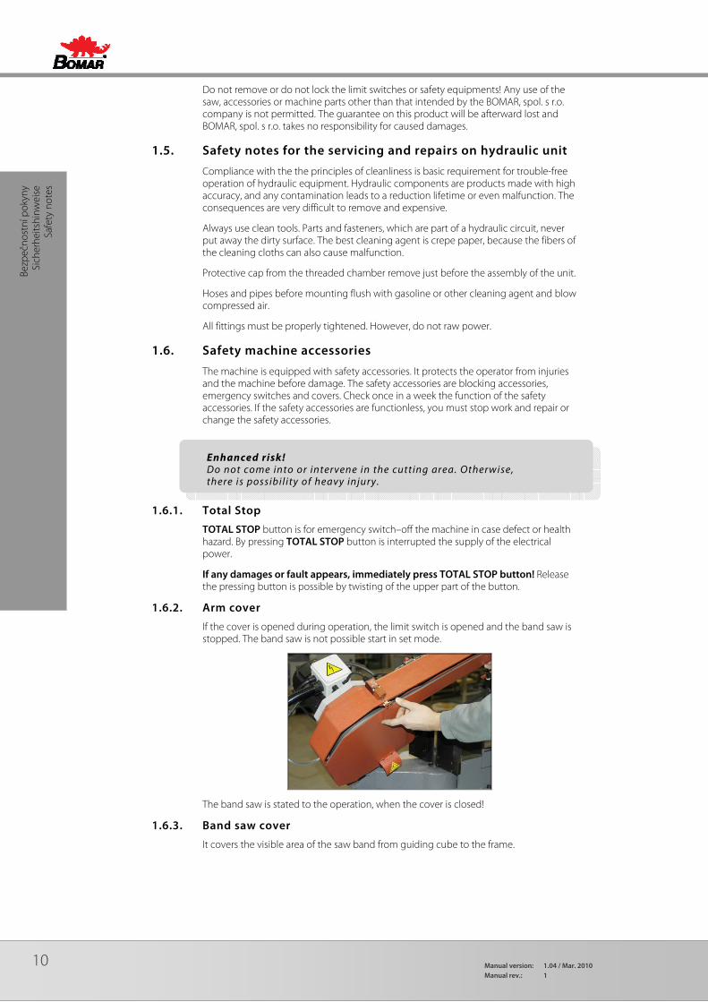
1.6.2. Arm cover
If the cover is opened during operation, the limit switch is opened and the band saw is stopped. The band saw is not possible start in set mode.
The band saw is stated to the operation, when the cover is closed!
1.6.3. Band saw cover
It covers the visible area of the saw band from guiding cube to the frame.
Enhanced risk! Do not come into or intervene in the cutting area. Otherwise, there is possibil ity of heavy injury.

11
Bezpečnostní pokyny Sicherheitshinw
eise Safety notes
Never turn-ON saw band when cover is not mounted!
1.6.4. Saw band stretching and rupture inspection
This device checks the saw band tension and causes immediate machine stop if the band incidentally ruptures.
The device includes a limit switch. Its adjustment is described in chapter „Servicing and adjusting“. Check the switch carefully and periodically – adjust it if necessary.
1.7. Safety notes for the cooling
1.7.1. Instructions for first help
1. Pull off and safely remove polluted, soaked clothing.
2. For breathing, go out in the fresh air or look for first aid treatment.
3. Wash with water or use crèmes for contact with the skin.
4. Flush with water for eyes and look for first aid treatment.
5. For swallowing, drink a lot of water and induce vomiting. Look for medical help.
Attention! When handling cooling agents always wear hazardous
f luid-proof gloves! Wear protective goggles! Cooling l iquid can get in contact with your eyes and may
cause permanent severe injuries

12 Manual version: 1.04 / Mar. 2010Manual rev.: 1
Bezp
ečno
stní
pok
yny
Sich
erhe
itshi
nwei
se
Safe
ty n
otes
1.8. Umístění štítku stroje / Maschinenschild position / Position of machine label
Machine label is placed on saw band base.

13
Bezpečnostní pokyny Sicherheitshinw
eise Safety notes
1.9. Umístění bezpečnostních značek / Verteilung der Sicherheitszeichen / Position of safety symbols

14 Manual version: 1.04 / Mar. 2010Manual rev.: 1
Dok
umen
tace
str
oje
Dok
umen
tatio
n de
r Mas
chin
en
Mac
hine
doc
umen
tatio
n SD
okum
enta
cest
roje
15
aokumentace stroje
Dokum
entation der Maschinen
Machine docum
entation
2. Machine documentation
16 Manual version: 1.04 / Mar. 2010Manual rev.: 1
Dok
umen
tace
str
oje
Dok
umen
tatio
n de
r Mas
chin
en
Mac
hine
doc
umen
tatio
n SD
okum
enta
cest
roje
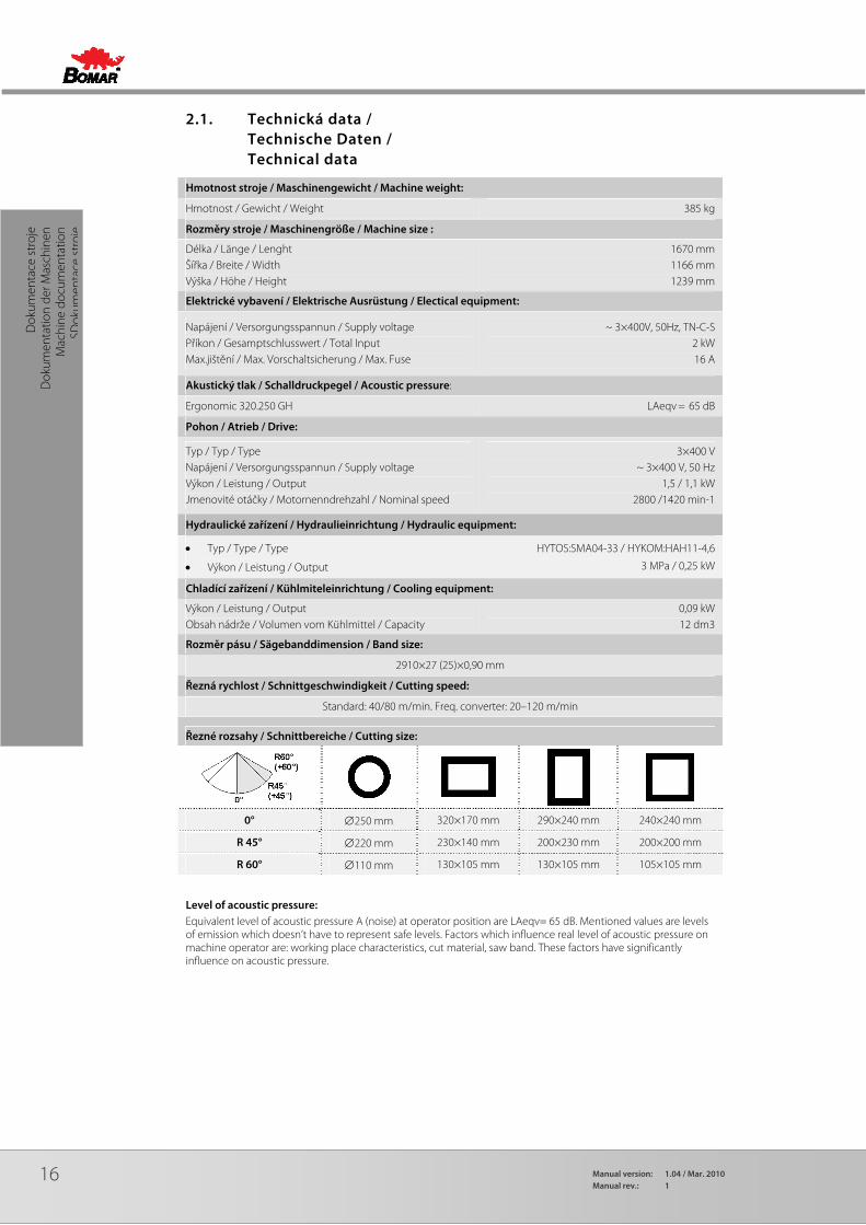
2.1. Technická data / Technische Daten / Technical data
Hmotnost stroje / Maschinengewicht / Machine weight:
Hmotnost / Gewicht / Weight 385 kg
Rozměry stroje / Maschinengröße / Machine size :
Délka / Länge / Lenght Šířka / Breite / Width Výška / Höhe / Height
1670 mm 1166 mm 1239 mm
Elektrické vybavení / Elektrische Ausrüstung / Electical equipment:
Napájení / Versorgungsspannun / Supply voltage Příkon / Gesamptschlusswert / Total Input Max.jištění / Max. Vorschaltsicherung / Max. Fuse
~ 3×400V, 50Hz, TN-C-S 2 kW 16 A
Akustický tlak / Schalldruckpegel / Acoustic pressure:
Ergonomic 320.250 GH LAeqv = 65 dB
Pohon / Atrieb / Drive:
Typ / Typ / Type Napájení / Versorgungsspannun / Supply voltage Výkon / Leistung / Output Jmenovité otáčky / Motornenndrehzahl / Nominal speed
3×400 V ~ 3×400 V, 50 Hz
1,5 / 1,1 kW 2800 /1420 min-1
Hydraulické zařízení / Hydraulieinrichtung / Hydraulic equipment:
• Typ / Type / Type
• Výkon / Leistung / Output
HYTOS:SMA04-33 / HYKOM:HAH11-4,6
3 MPa / 0,25 kW
Chladící zařízení / Kühlmiteleinrichtung / Cooling equipment:
Výkon / Leistung / Output Obsah nádrže / Volumen vom Kühlmittel / Capacity
0,09 kW 12 dm3
Rozměr pásu / Sägebanddimension / Band size:
2910×27 (25)×0,90 mm
Řezná rychlost / Schnittgeschwindigkeit / Cutting speed:
Standard: 40/80 m/min. Freq. converter: 20–120 m/min
Řezné rozsahy / Schnittbereiche / Cutting size:
0° ∅250 mm 320×170 mm 290×240 mm 240×240 mm
R 45° ∅220 mm 230×140 mm 200×230 mm 200×200 mm
R 60° ∅110 mm 130×105 mm 130×105 mm 105×105 mm
Level of acoustic pressure: Equivalent level of acoustic pressure A (noise) at operator position are LAeqv= 65 dB. Mentioned values are levels of emission which doesn’t have to represent safe levels. Factors which influence real level of acoustic pressure on machine operator are: working place characteristics, cut material, saw band. These factors have significantly influence on acoustic pressure.
17
aokumentace stroje
Dokum
entation der Maschinen
Machine docum
entation
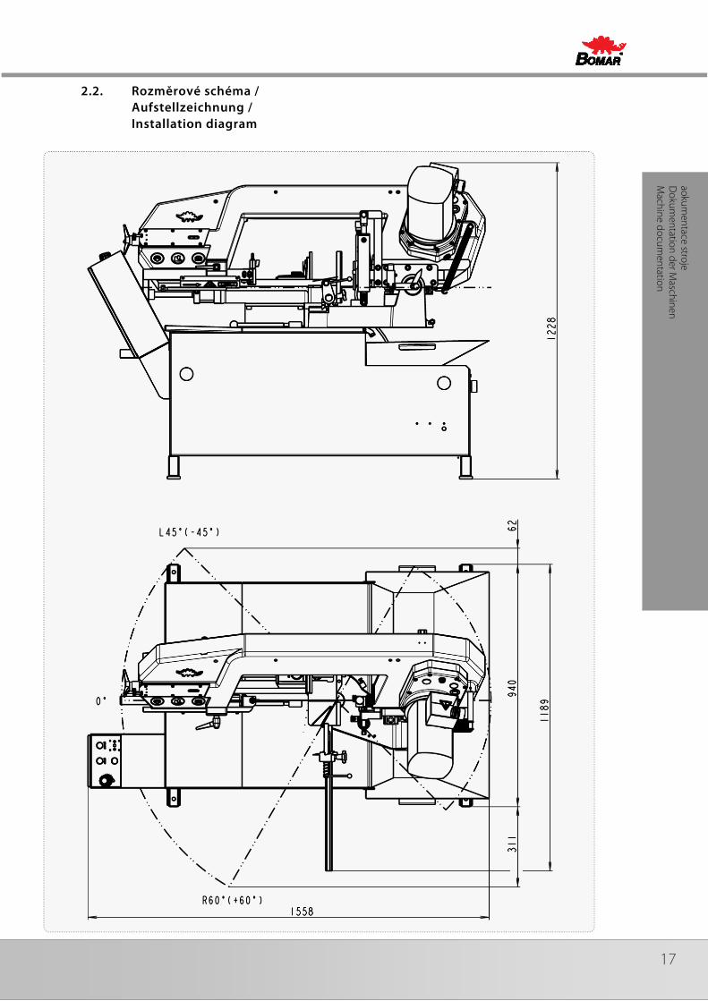
2.2. Rozměrové schéma / Aufstellzeichnung / Installation diagram
18 Manual version: 1.04 / Mar. 2010Manual rev.: 1
Dok
umen
tace
str
oje
Dok
umen
tatio
n de
r Mas
chin
en
Mac
hine
doc
umen
tatio
n SD
okum
enta
cest
roje
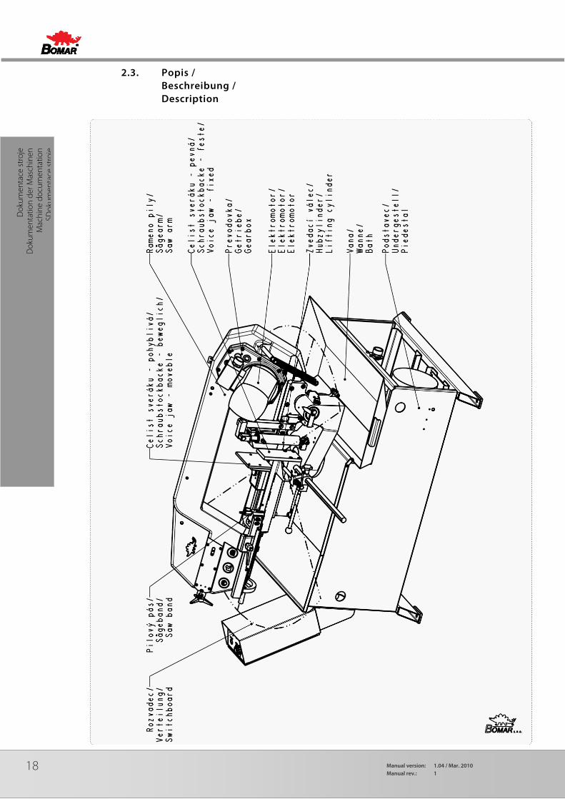
2.3. Popis / Beschreibung / Description

19
aokumentace stroje
Dokum
entation der Maschinen
Machine docum
entation
2.4. Transportation and stocking
2.4.1. Conditions for transportation and stocking
Keep recommendations for the manufacturers for transportation and stocking! If the recommendations are not kept, damage can occur to the machine.
• Don’t use a forklift truck for handling the machine, if you do not have license for it!
• Don’t move under suspended loads! Fault in lifting device may cause serious injury.
• Keep a safe distance from the machine during the transport.
• Temperature of the air from -25°C to 55°C, for a short term (max. 24 hours) temperature of the air until 70°C
• Do not expose the machine to radiation (for example microwave radiation, ultraviolet radiation, laser radiation, x-ray radiation). Radiation can cause problems with the machine function and deteriorating condition of the isolation.
• Take measures, to prevent damage by dampness, by vibrations and by shakes.
2.4.2. Transport and stocking preparations
Close the vice and thoroughly oil all blank surfaces.
Lower the saw frame to the lowest position.
Make sure to empty the machine of all traces of the cooling agent.
Fasten all loose parts securely to the machine.
Pack and wrap the control desk securely to avoid damage during transport.
Fix the stickers stating the minimum approximate machine weight to at least five well visible places.
2.4.3. Transport and stocking
The machine must be secured during transportation. Screw on the palette to the floor of the van or the trailer. Be careful that the machine is not damaged during transportation. Store the machine only under conditions mentioned in the manual, to avoid damage of the machine.
It is forbidden to handle the machine any other way, than it is written in this operating instructions, the machine can be damaged.

20 Manual version: 1.04 / Mar. 2010Manual rev.: 1
Dok
umen
tace
str
oje
Dok
umen
tatio
n de
r Mas
chin
en
Mac
hine
doc
umen
tatio
n SD
okum
enta
cest
roje
2.4.4. Transportní schéma / Transport schema / Transport scheme

21
aokumentace stroje
Dokum
entation der Maschinen
Machine docum
entation
Attention! I f the ambient temperature drops below 15 ˚ C is required before operating the machine to have switch on hydraulic unit around 10 minutes and then made several motion few times (for example, in manual mode) by all hydraulic cylinders. The reason is to heat hydraulic oil to the operating temperature for proper function of the pressure switches (and choke).
2.5. Activation
2.5.1. Machine working conditions
Keep the conditions of the manufacturer for machine operating! If recommendations are not kept, damage can occur to the machine.
The manufacturer warrants the correct function of the machine for these conditions:
• At temperature air from 5°C to 40°C, the temperature average during 24 hours must not exceed over 35°C.
• At relative dampness of the air in the extend from 30% to 95% (not concentrate). Altitude lower than 1000 metres.
• Do not expose the machine to the radiation (for example microwave radiation, ultra-violet radiation, laser radiation, x-ray radiation). Radiation can cause problems with the machine function and deteriorating condition of the isolation.
2.6. Band saw unpacking and assembling
Remove the packing from the machine and unpack all parts.
If the hydraulic unit is outside the machine (the machine only connected hoses and cables), it needs to be placed and mounted on a solid basis (floors, etc.). The mounting holes are used on the bottom (bases) of the tank.
2.6.1. Machine installing and levelling
Check the floor supporting capacity before machine installing. If the floor capacity does not agree with requirements, you must prepare the necessary base for the machine.
Minimal requirement:
machine weight – Ergonomic 320.250 GH – 385 kg
+ weight of accessories
+ maximum weight of material
• The machine must be levelled at the horizontal position. All feet of the machine must touch with the floor after levelling
• The machine must be levelled by means of the calibrated spirit level. Spirit level is put on the vice area. Set the roller conveyors according to the spirit level.
• For machine levelling, take care that there is sufficient available space for operation, repair work, servicing of the machine and handling the material..
• The machine including appended parts and accessories must be visible from the place of operation.
2.6.2. Machine disposal after lifetime
Blown out all service fluids (cooling liquid, hydraulic oil) into designated reservoir. Dismantle machine into separate parts and dispose them in accordance with valid directives.
Attention! Switch off the main switch and lock it , before you start assembly! Otherwise, there is possibil ity of hazardous machine starting.

22 Manual version: 1.04 / Mar. 2010Manual rev.: 1
Dok
umen
tace
str
oje
Dok
umen
tatio
n de
r Mas
chin
en
Mac
hine
doc
umen
tatio
n SD
okum
enta
cest
roje
2.6.3. First run of the power pack
Before the first run check:
• The direction of the Pump, while run the power pack for max. 2seconds.
• The cooling fan of the motor has to rotate in the same direction as the arrow on the top of the motor cowling indicates.
• In case of wrong rotational direction, the electrical phase in the connection box is to be changed. This check is required after every disconnection from the power source
• Wiring matches with electrical and hydraulic diagrams
• the electric motors (pump and cooler) are properly connected and have the prescribed rotation
• the hydraulic accumulator with nitrogen gas to the specified value
• aux. elements work right (thermometer, level gauge, heater)
First run (Attention – working pressure on securing valve is set by producer in accoring the hydraulic diagram):
• In the short intervals activate an electric pump
• check for leaks and noise
• Bleed the hydraulic circuit
• if possible, test the circuit function with minimum load
• test the electrical equipment
• during operation monitor measuring equipment, noise, height and temperature of oil in the tank
• During this time a careful bleeding off for the whole hydraulic system is necessary. In case there is no bleeder port, the power pack will bleed itself after a while via the air breather on the tank or the return line filter.
• After multiple start-up.
2.6.4. Filling the reservoir with hydraulic oil
Oil regulations and recommendations of the manufacturer in the technical documentation (appendix) are to be carefully observed. For standard power packs we recommend the oiltype OH-HM32 (DIN 51524) of all known oil manufacturers.
Power packs have to be filled up with clean, pre-filtered oil! The purity of the hydraulic fluid must correspond to the class 10 NAS 1638 (reachable with filter ß =75)!
Filling from container, such as barrels, backets, etc. is not recommended or permitted!
The maximum oil level will be shown on the upper marking at the dipstick or the sight level glass. Prevent overfilling. The maximum filling rate of 15 l/min shouldn´t be exceed.
Oil type Kinematic viscosity v in mm²/s in relationship to the fluid temperatur Freezing point
0°C 20°C 40°C 60°C 80°C °C
OH-HM 32 220 100 32 15 7 -40
OH-HM 46 400 170 46 18 11 -30
OH-HM 68 700 170 68 26 14 -28
OH-HV 32 180 67 32 17 11 -40
OH-HV 46 350 110 46 25 14 -36

23
aokumentace stroje
Dokum
entation der Maschinen
Machine docum
entation
2.6.5. Kotevní plan / Verankerungsplan / Grounding plan
24 Manual version: 1.04 / Mar. 2010Manual rev.: 1
Dok
umen
tace
str
oje
Dok
umen
tatio
n de
r Mas
chin
en
Mac
hine
doc
umen
tatio
n SD
okum
enta
cest
roje
2.7. Electrical connection
Electrical parameters of the machine:
• Service voltage: ~ 3×400 V, 50 Hz, TN-C-S
• Total input / Max. fuse: 2 kW / 16 A
Before connecting switch off the main switch of the power supply circuit for the machine and ensure dry place when doing connecting works!
Service voltage must agree with the line voltage! Crosscut of the supply line must respond with rated current for max. machine load.
Connect the service cable of the machine on the clamps of the electric distribution.
In case the machine is connected with a direct connection, an extra main switch must be added which can be locked in zero position.
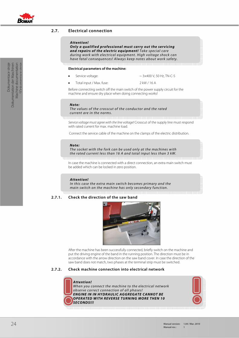
2.7.1. Check the direction of the saw band
After the machine has been successfully connected, briefly switch on the machine and put the driving engine of the band in the running position. The direction must be in accordance with the arrow direction on the saw band cover. In case the direction of the saw band does not match, two phases at the terminal strip must be switched.
2.7.2. Check machine connection into electrical network
Attention! Only a qualified professional must carry out the servicing and repairs of the electric equipment! Take special care during work with electrical equipment. High voltage shock can have fatal consequences! Always keep notes about work safety.
Note: The values of the crosscut of the conductor and the rated current are in the norms.
Note: The socket with the fork can be used only at the machines with the rated current less than 16 A and total input less than 3 kW.
Attention! In this case the extra main switch becomes primary and the main switch on the machine has only secondary function.
Attention! When you connect the machine to the electrical network observe correct connection of all phases! ENGINE IN IN HYDRAULIC AGGREGATE CANNOT BE OPERATED WITH REVERSE TURNING MORE THEN 10 SECONDS!!!
25
aokumentace stroje
Dokum
entation der Maschinen
Machine docum
entation
2.8. Filling of the cooling system
Prepare the mixture of the water and the cooling liquid. Keep the concentration specified by manufacturer. Shift away the cover from the drainage hole. Fill the mixture of the water and the cooling liquid to the tank of the cooling system. Area of the tank for the cooling liquid is discovered from the chapter Technical data.
Let the drainage hole opened and with the sieve during operation, because it secures the right work of the cooling system. Filling the tank with the cooling liquid, take care that the liquid does not drip out of the tank and the tank does not overflowed.
2.9. Check machine function
Check, if the machine or some parts of the machine were not damaged during transport.
Check, if covers are installed and functional. Check by means of the Tenzomat if the saw band is correctly stretched. If it is necessary, you can stretch the saw band according to chapter Selection and replacement of the saw band. Values of the saw band stretching are on the Tenzomat. Switch on the main switch and check the motors and systems (saw band drive, hydraulic pump, cooling pump, chips conveyor).
Open and close the main vice. Turn the saw frame of the band saw from one outer position to other outer position. Raise the saw frame to the top position and drop the saw frame to the lowest position.
Start the machine with the cooling pump and let it run without load until the cooling system will be filled with cooling liquid. As soon as the cooling liquid starts to escape from the nozzles of the cooling system, the cooling system is ready for the operation. Carry one cycle of cutting without material. Check, if the machine runs with no irregularities. If all machine functions are right, the machine is ready for operation..
2.10. Saw band
Refit the saw band cover only after you have installed and tightened the saw band.
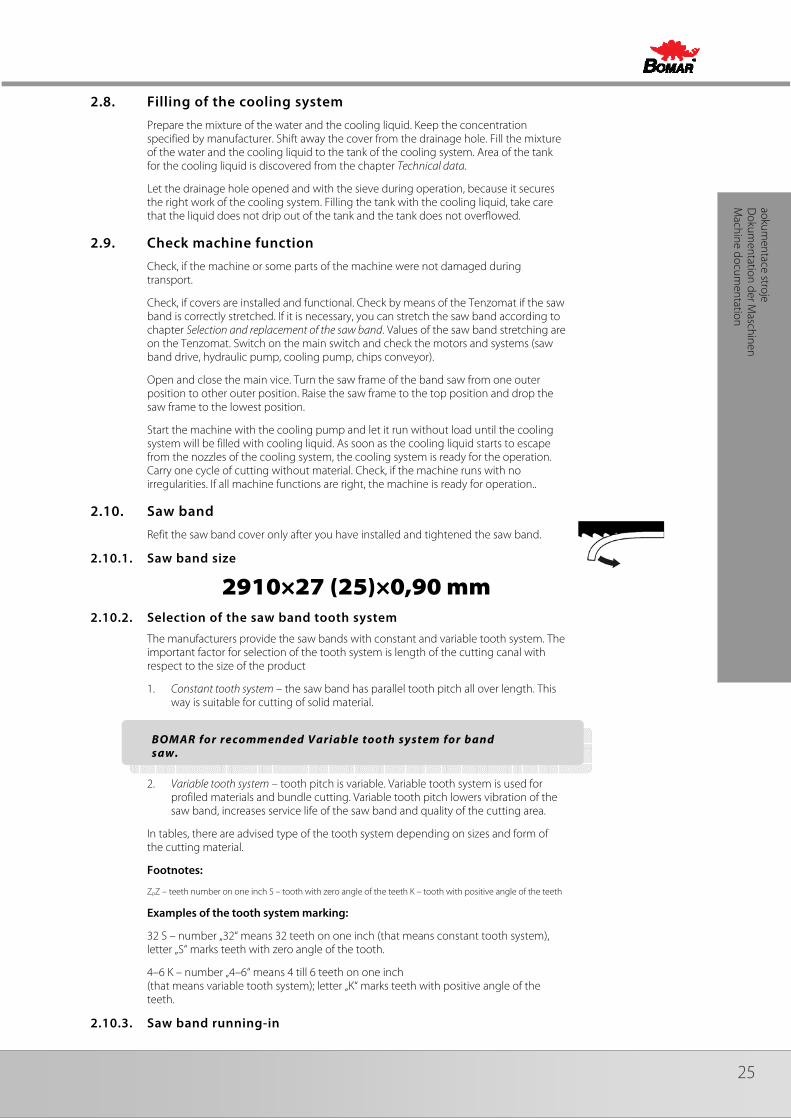
2.10.1. Saw band size
2910×27 (25)×0,90 mm 2.10.2. Selection of the saw band tooth system
The manufacturers provide the saw bands with constant and variable tooth system. The important factor for selection of the tooth system is length of the cutting canal with respect to the size of the product
1. Constant tooth system – the saw band has parallel tooth pitch all over length. This way is suitable for cutting of solid material.
2. Variable tooth system – tooth pitch is variable. Variable tooth system is used for profiled materials and bundle cutting. Variable tooth pitch lowers vibration of the saw band, increases service life of the saw band and quality of the cutting area.
In tables, there are advised type of the tooth system depending on sizes and form of the cutting material.
Footnotes:
ZpZ – teeth number on one inch S – tooth with zero angle of the teeth K – tooth with positive angle of the teeth
Examples of the tooth system marking:
32 S – number „32“ means 32 teeth on one inch (that means constant tooth system), letter „S“ marks teeth with zero angle of the tooth.
4–6 K – number „4–6“ means 4 till 6 teeth on one inch (that means variable tooth system); letter „K“ marks teeth with positive angle of the teeth.
2.10.3. Saw band running-in
BOMAR for recommended Variable tooth system for band saw.
26 Manual version: 1.04 / Mar. 2010Manual rev.: 1
Dok
umen
tace
str
oje
Dok
umen
tatio
n de
r Mas
chin
en
Mac
hine
doc
umen
tatio
n SD
okum
enta
cest
roje
Running-in: Cut the material with the frame lowering reduced to 50% only. When vibrations occur increase or decrease the band speed.
When cutting small pieces run the band until approximately 300 cm2 of material has been cut. When cutting large pieces run the band for 15 minutes approximately. When the band has been run, increase the lowering-speed to normal speed. The running in of the saw band avoids micro-breaks on the cutting edges of new saw band ensuing from first excessive stress. This would decrease service life substantially. The optimal running in of the saw band produces ideal rounded cutting edges and therefore the conditions for an optimal service life.
27
aokumentace stroje
Dokum
entation der Maschinen
Machine docum
entation
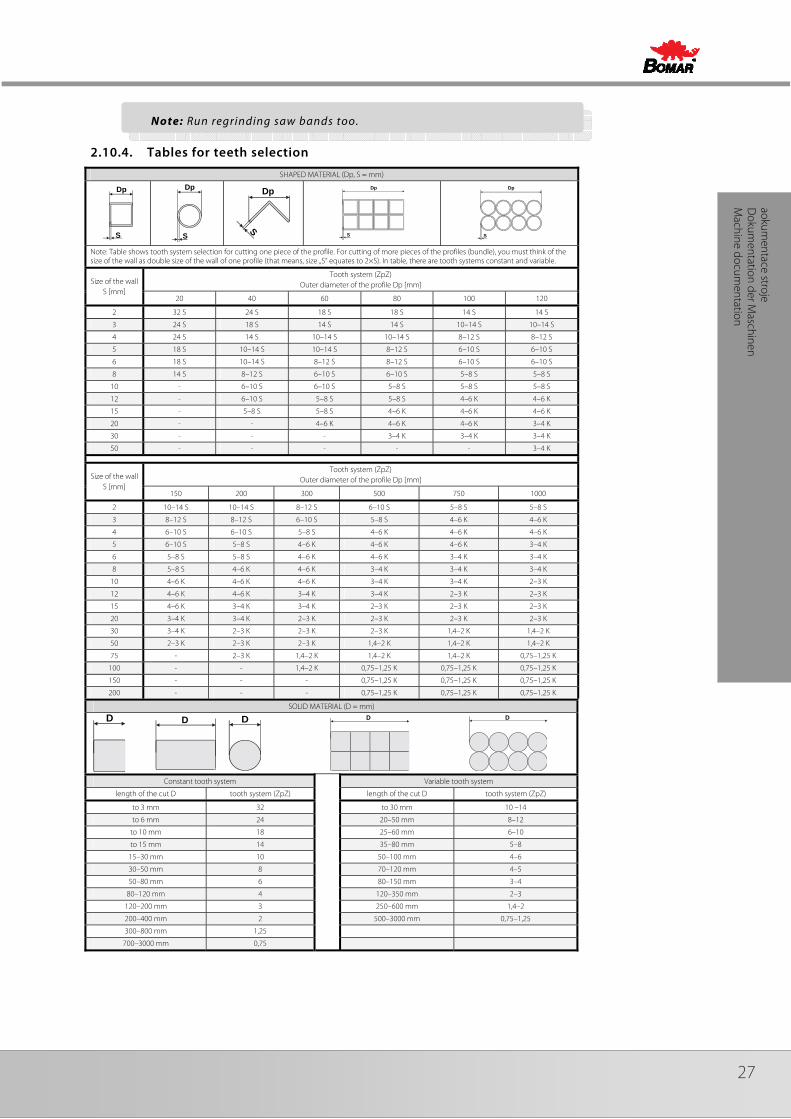
2.10.4. Tables for teeth selection
SHAPED MATERIAL (Dp, S = mm)
Dp
S
Dp
S S
Dp
Dp
S
Dp
S
Note: Table shows tooth system selection for cutting one piece of the profile. For cutting of more pieces of the profiles (bundle), you must think of the size of the wall as double size of the wall of one profile (that means, size „S“ equates to 2×S). In table, there are tooth systems constant and variable.
Size of the wall S [mm]
Tooth system (ZpZ) Outer diameter of the profile Dp [mm]
20 40 60 80 100 120
2 32 S 24 S 18 S 18 S 14 S 14 S
3 24 S 18 S 14 S 14 S 10–14 S 10–14 S
4 24 S 14 S 10–14 S 10–14 S 8–12 S 8–12 S
5 18 S 10–14 S 10–14 S 8–12 S 6–10 S 6–10 S
6 18 S 10–14 S 8–12 S 8–12 S 6–10 S 6–10 S
8 14 S 8–12 S 6–10 S 6–10 S 5–8 S 5–8 S
10 - 6–10 S 6–10 S 5–8 S 5–8 S 5–8 S
12 - 6–10 S 5–8 S 5–8 S 4–6 K 4–6 K
15 - 5–8 S 5–8 S 4–6 K 4–6 K 4–6 K
20 - - 4–6 K 4–6 K 4–6 K 3–4 K
30 - - - 3–4 K 3–4 K 3–4 K
50 - - - - - 3–4 K
Size of the wall S [mm]
Tooth system (ZpZ) Outer diameter of the profile Dp [mm]
150 200 300 500 750 1000
2 10–14 S 10–14 S 8–12 S 6–10 S 5–8 S 5–8 S
3 8–12 S 8–12 S 6–10 S 5–8 S 4–6 K 4–6 K
4 6–10 S 6–10 S 5–8 S 4–6 K 4–6 K 4–6 K
5 6–10 S 5–8 S 4–6 K 4–6 K 4–6 K 3–4 K
6 5–8 S 5–8 S 4–6 K 4–6 K 3–4 K 3–4 K
8 5–8 S 4–6 K 4–6 K 3–4 K 3–4 K 3–4 K
10 4–6 K 4–6 K 4–6 K 3–4 K 3–4 K 2–3 K
12 4–6 K 4–6 K 3–4 K 3–4 K 2–3 K 2–3 K
15 4–6 K 3–4 K 3–4 K 2–3 K 2–3 K 2–3 K
20 3–4 K 3–4 K 2–3 K 2–3 K 2–3 K 2–3 K
30 3–4 K 2–3 K 2–3 K 2–3 K 1,4–2 K 1,4–2 K
50 2–3 K 2–3 K 2–3 K 1,4–2 K 1,4–2 K 1,4–2 K
75 - 2–3 K 1,4–2 K 1,4–2 K 1,4–2 K 0,75–1,25 K
100 - - 1,4–2 K 0,75–1,25 K 0,75–1,25 K 0,75–1,25 K
150 - - - 0,75–1,25 K 0,75–1,25 K 0,75–1,25 K
200 - - - 0,75–1,25 K 0,75–1,25 K 0,75–1,25 K
SOLID MATERIAL (D = mm)
D
D
D
D
D
Constant tooth system Variable tooth system
length of the cut D tooth system (ZpZ) length of the cut D tooth system (ZpZ)
to 3 mm 32 to 30 mm 10 –14
to 6 mm 24 20–50 mm 8–12
to 10 mm 18 25–60 mm 6–10
to 15 mm 14 35–80 mm 5–8
15–30 mm 10 50–100 mm 4–6
30–50 mm 8 70–120 mm 4–5
50–80 mm 6 80–150 mm 3–4
80–120 mm 4 120–350 mm 2–3
120–200 mm 3 250–600 mm 1,4–2
200–400 mm 2 500–3000 mm 0,75–1,25
300–800 mm 1,25
700–3000 mm 0,75
Note: Run regrinding saw bands too.

28 Manual version: 1.04 / Mar. 2010Manual rev.: 1
Ovl
ádán
í str
oje
Bedi
enun
g de
r Mas
chin
e M
achi
ne c
ontr
ol
29
Ovládání stroje
Bedienung der Maschine
Machine control
3. Machine control

30 Manual version: 1.04 / Mar. 2010Manual rev.: 1
Ovl
ádán
í str
oje
Bedi
enun
g de
r Mas
chin
e M
achi
ne c
ontr
ol
3.1. Main switch
Main switch – It is on the vice side of the distributing box.
3.2. Control panel
3.2.1. Control panel – for machine without frequency converter
1 Switch of the cutting speed Choice of the cutting speed during cutting (40 or 80 m. min-1).
2 TOTAL STOP button In case of emergency, the machine is stated to the order!
3 START It starts the semi-automatic cycle
4 STOP It stops the semi-automatic cycle, lifts the saw frame to the top and stops the saw band drive.
5 Governing valve Adjust the speed of the arm sinking to the cut by governing valve. Notice: If you keep closing the throttle valve too tightly, the valve seat may wear off which causes its leakage. Therefore, close the valve always gently.
6 543
21

31
Ovládání stroje
Bedienung der Maschine
Machine control
6 Saw arm height setting You can limit the arm height according to the scale of the control panel.
3.2.2. Control panel – for machine with frequency converter
1 Switch of the cutting speed Choice of the cutting speed during cutting in range 20–120 m. min-1.
2 TOTAL STOP button In case of emergency, the machine is stated to the order!
3 START It starts the semi-automatic cycle
4 STOP It stops the semi-automatic cycle, lifts the saw frame to the top and stops the saw band drive.
5 Governing valve Adjust the speed of the arm sinking to the cut by governing valve. Notice: If you keep closing the throttle valve too tightly, the valve seat may wear off which causes its leakage. Therefore, close the valve always gently.
6 Saw arm height setting You can limit the arm height according to the scale of the control panel.
3.3. Cutting
3.3.1. Semiautomatic cycle
1. Open the vice jaws by hand wheel.
2. Set the length stop to the desired length of the material.
3. Set the desired cutting angle.
4. Insert the material and pull it to the length stop.
5. Pull vice jaws about 5 mm from the material by hand wheel.
6. Set the saw band speed.
7. Set the speed of the saw frame sinking.
6 543
21
120 20
32 Manual version: 1.04 / Mar. 2010Manual rev.: 1
Ovl
ádán
í str
oje
Bedi
enun
g de
r Mas
chin
e M
achi
ne c
ontr
ol
8. Start saw band drive by button START. The vice clamps the material. Semi-automatic cycle of the cutting is started.
9. After the material cutting, the saw frame is lifted to the top position, the saw band drive is stopped and the vice is opened.
10. Remove the cut. Now you can repeat whole progress.
3.4. Cycle breaking
• Button STOP
Cycle is interrupted by pressing STOP button. The arm is lifted to the top position and the saw band drive is stopped.
• Emergency button TOTAL STOP
In case of the risk, press button TOTAL STOP! After pressing TOTAL STOP button, saw band drive is immediately broken and the arm sinking is stopped.
• Reactivation
Turn button TOTAL STOP according to the arrows (on the button) By pressing button START, you can start the cycle. The arm is lifted to the top position and the saw band starts the cycle.
3.5. Band saw adjusting
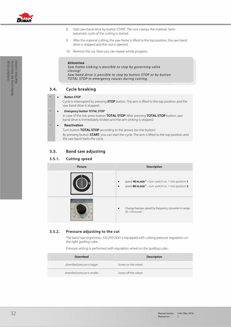
3.5.1. Cutting speed
Picture Description
• speed 40 m.min-1 – turn switch no. 1 into position 1
• speed 80 m.min-1 – turn switch no. 1 into position 2
• Change bansaw speed by frequency converter in range 20–120 m.min-1.
3.5.2. Pressure adjusting to the cut
The band saw ergonomic 320.250 DGH is equipped with cutting pressure regulation on the right guiding cube.
Pressure setting is performed with regulation wheel on the guiding cube..
Downfeed Description
downfeed pressure is bigger Screw on the wheel
downfeed pressure is smaller Screw off the wheel
Attention Saw frame sinking is possible to stop by governing valve closing! Saw band drive is possible to stop by button STOP or by button TOTAL STOP in emergency causes during cutting.

33
Ovládání stroje
Bedienung der Maschine
Machine control
One visible neck
Solid material over ∅200 mm.
Two visible necks
Solid material to ∅80 -∅200 mm.
Three visible necks Pipes and shaped material with surface from 10 - 15 mm. I- shaped material from 200 - 280 mm.
Solid material to ∅80 mm.
Four visible necks Pipes and shapes material with surface to 10 mm. I - shaped material to 200 mm .
3.5.3. Setting of the material length
Release the securing screw, move the length stop on the desired length of the material and fasten the securing screw.
3.5.4. Optimal adjusting of the guide cubes span
If you want to achieve a smooth and precise cut, it is helpful to position the guide cube as close as possible to the material.
Note: The length stop makes bounce l istel of the material, so that the saw band will be not compressed in the cut. Turn the lever to the arrow direction.
34 Manual version: 1.04 / Mar. 2010Manual rev.: 1
Ovl
ádán
í str
oje
Bedi
enun
g de
r Mas
chin
e M
achi
ne c
ontr
ol
1. Release the lever of the left listel and move left part of the guide apparatus so that the left guide cube edge is as close to the cut material as possible.
2. Lower the frame to the lower position and check the position of the guide cube towards vice loading area. The guide cube must be a distance of at least 10 mm from the vice loading area.
3. Tighten the lever of the gib and check the guide cube setting once more for possible collision with binding table or vice jaw.
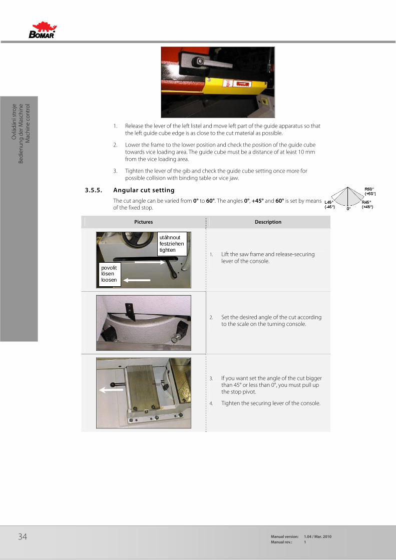
3.5.5. Angular cut setting
The cut angle can be varied from 0° to 60°. The angles 0°, +45° and 60° is set by means of the fixed stop.
Pictures Description
povolit lösen loosen
utáhnout festziehen tighten
1. Lift the saw frame and release-securing lever of the console.
2. Set the desired angle of the cut according to the scale on the turning console.
3. If you want set the angle of the cut bigger than 45° or less than 0°, you must pull up the stop pivot.
4. Tighten the securing lever of the console.

35
Ovládání stroje
Bedienung der Maschine
Machine control
Pictures Description
angle < 0°
angle ≥ 0°
5. Shift the vice according to setting angle of the cutting. Shift the vice to the right for angle of the cut, which is less than 0°, shift the vice to the left for angle of the cut 0° or for angle of the cut, which is bigger than 0°.
3.5.6. Brush adjustment
The brush has essential influence on cutting performance, saw band lifetime and lifetime of wheels and hard metal guides and finally cut accuracy. Therefore the brush has to be checked during every shift.
1. Release the tightening screw of the brush so that it is possible to move with the brush.
2. Get the brush closer to the saw band teeth. After the brush is set, its ends must not reach the saw band teeth bottoms..
3. Tighten the screw again and turn on the band driver.
4. If the chip removing brush is correctly fastened the brush moves and turns smoothly with the saw band.
Attention! Moving the moving part of vice must be carried out at arm raised, arm angle is zero and closed jaw vice Moving part of vice must always be in the rearmost position, otherwise there is a conflict with the housing shoulder vice.

36 Manual version: 1.04 / Mar. 2010Manual rev.: 1
Ovl
ádán
í str
oje
Bedi
enun
g de
r Mas
chin
e M
achi
ne c
ontr
ol
3.6. Material insertion
• Never walk under a suspended load!
• Never climb onto the gravity-roller conveyor!
• Do not hold the material for clamping material to the vice! The vice can cause injury!
3.6.1. Handling agent selection
• Use the strong handling agents to lift and transfer the material!
• Handle with the material only with the lift truck or use the suspension strands and the crane!
• Do not use the lift truck or crane in case that you do not have the license to handle with it!
3.6.2. Insertion
Insert material to the vice and ensure that the material cannot move in the vice or fall from the vice after the clamping. If you cut long pieces of the material (for example rod, tube), you must use the roller conveyors for material shifting to the band saw. Contact Bomar for more information about roller conveyors
Make sure the conveyor is long enough and the material cannot tip off the conveyor.
Be especially careful with round materials that it always stays on two vertical rollers and that it cannot fall off the conveyor!
3.6.3. Bundle material cutting
If you want to cut the material in the bundle, there are suggestions for the positioning of bundles
Round material bundle: Take care especially with round material that the bars are put according to the picture. If the bars are put differently, you may have problems with movement.
Always weld the material at the rear end of the bundle to secure it from moving.
Before welding always, switch the machine off at the main switch! The magnetic fields, which often occur during welding, may damage the controls!
Square material bundle:
Attention: Not all material shapes are suitable for bundle cuts. Keep the recommendation of your supplier of the saw bands for material insertion to the bundle.

37
Údržba stroje
Wartung
Machine service
4. Machine service
38 Manual version: 1.04 / Mar. 2010Manual rev.: 1
Údr
žba
stro
je
War
tung
/
Mac
hine
ser
vice
4.1. Saw band dismantling and installation
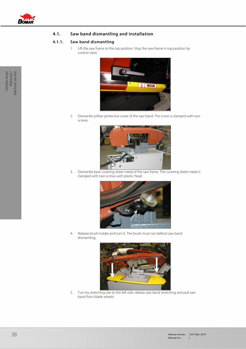
4.1.1. Saw band dismantling
1. Lift the saw frame to the top position. Stop the saw frame in top position by control valve.
2. Dismantle yellow protective cover of the saw band. The cover is clamped with two screws.
3. Dismantle back covering sheet metal of the saw frame. The covering sheet metal is
clamped with two screws with plastic head.
4. Release brush holder and turn it. The brush must not defend saw band dismantling.
5. Turn by stretching star to the left side, release saw band stretching and pull saw
band from blade wheels.
39
Údržba stroje
Wartung
Machine service
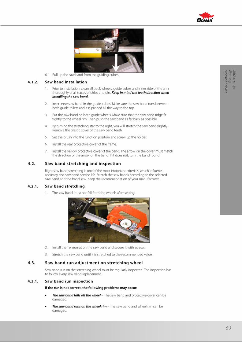
6. Pull up the saw band from the guiding cubes.
4.1.2. Saw band installation
1. Prior to installation, clean all track wheels, guide cubes and inner side of the arm thoroughly of all traces of chips and dirt. Keep in mind the teeth direction when installing the saw band.
2. Insert new saw band in the guide cubes. Make sure the saw band runs between both guide rollers and it is pushed all the way to the top.
3. Put the saw band on both guide wheels. Make sure that the saw band ridge fit tightly to the wheel rim. Then push the saw band as far back as possible.
4. By turning the stretching star to the right, you will stretch the saw band slightly. Remove the plastic cover of the saw band teeth.
5. Set the brush into the function position and screw up the holder.
6. Install the rear protective cover of the frame.
7. Install the yellow protective cover of the band. The arrow on the cover must match the direction of the arrow on the band. If it does not, turn the band round.
4.2. Saw band stretching and inspection
Right saw band stretching is one of the most important criteria’s, which influents accuracy and saw band service life. Stretch the saw bands according to the selected saw band and the band saw. Keep the recommendation of your manufacturer.
4.2.1. Saw band stretching
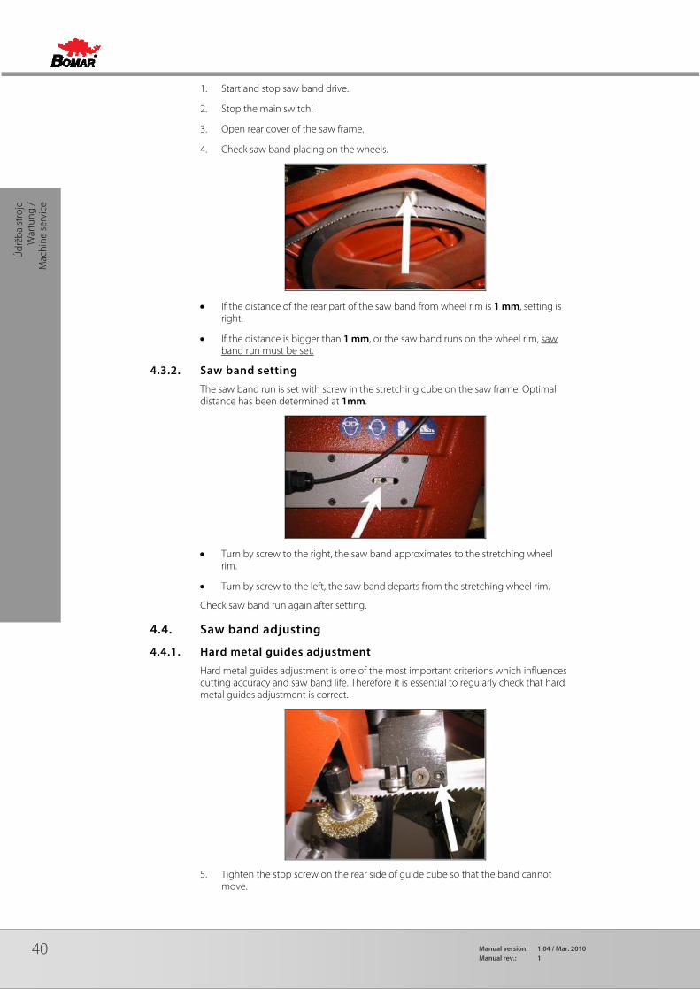
1. The saw band must not fall from the wheels after setting.
2. Install the Tenzomat on the saw band and secure it with screws.
3. Stretch the saw band until it is stretched to the recommended value.
4.3. Saw band run adjustment on stretching wheel
Saw band run on the stretching wheel must be regularly inspected. The inspection has to follow every saw band replacement.
4.3.1. Saw band run inspection
If the run is not correct, the following problems may occur:
• The saw band falls off the wheel – The saw band and protective cover can be damaged.
• The saw band runs on the wheel rim – The saw band and wheel rim can be damaged.
40 Manual version: 1.04 / Mar. 2010Manual rev.: 1
Údr
žba
stro
je
War
tung
/
Mac
hine
ser
vice
1. Start and stop saw band drive.
2. Stop the main switch!
3. Open rear cover of the saw frame.
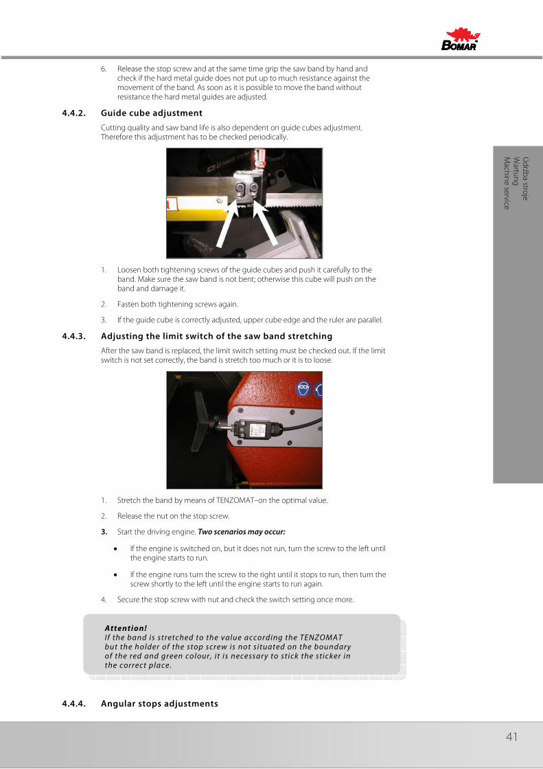
4. Check saw band placing on the wheels.
• If the distance of the rear part of the saw band from wheel rim is 1 mm, setting is right.
• If the distance is bigger than 1 mm, or the saw band runs on the wheel rim, saw band run must be set.
4.3.2. Saw band setting
The saw band run is set with screw in the stretching cube on the saw frame. Optimal distance has been determined at 1mm.
• Turn by screw to the right, the saw band approximates to the stretching wheel rim.
• Turn by screw to the left, the saw band departs from the stretching wheel rim.
Check saw band run again after setting.
4.4. Saw band adjusting
4.4.1. Hard metal guides adjustment
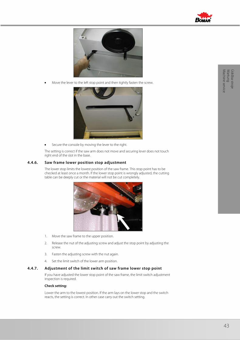
Hard metal guides adjustment is one of the most important criterions which influences cutting accuracy and saw band life. Therefore it is essential to regularly check that hard metal guides adjustment is correct.
5. Tighten the stop screw on the rear side of guide cube so that the band cannot move.
41
Údržba stroje
Wartung
Machine service
6. Release the stop screw and at the same time grip the saw band by hand and check if the hard metal guide does not put up to much resistance against the movement of the band. As soon as it is possible to move the band without resistance the hard metal guides are adjusted.
4.4.2. Guide cube adjustment
Cutting quality and saw band life is also dependent on guide cubes adjustment. Therefore this adjustment has to be checked periodically.
1. Loosen both tightening screws of the guide cubes and push it carefully to the band. Make sure the saw band is not bent; otherwise this cube will push on the band and damage it.
2. Fasten both tightening screws again.
3. If the guide cube is correctly adjusted, upper cube edge and the ruler are parallel.
4.4.3. Adjusting the limit switch of the saw band stretching
After the saw band is replaced, the limit switch setting must be checked out. If the limit switch is not set correctly, the band is stretch too much or it is to loose.
1. Stretch the band by means of TENZOMAT–on the optimal value.
2. Release the nut on the stop screw.
3. Start the driving engine. Two scenarios may occur:
• If the engine is switched on, but it does not run, turn the screw to the left until the engine starts to run.
• If the engine runs turn the screw to the right until it stops to run, then turn the screw shortly to the left until the engine starts to run again.
4. Secure the stop screw with nut and check the switch setting once more.
4.4.4. Angular stops adjustments
Attention! I f the band is stretched to the value according the TENZOMAT but the holder of the stop screw is not situated on the boundary of the red and green colour, it is necessary to stick the sticker in the correct place.

42 Manual version: 1.04 / Mar. 2010Manual rev.: 1
Údr
žba
stro
je
War
tung
/
Mac
hine
ser
vice
There are two fixed stops with adjustable screw on the console. The angular stop-points setting have to be periodically inspected to prevent inaccurate angular cuts.
In order to check angular stop settings, turn the arm to the fixed stop and put the protractor on the saw band and vice jaw.
If the angles are not set correctly, release the nut on the stop screw. You can set smaller angles by tightening the screw. You can set larger angles by loosening the screw.
Angle -45° Angle 0°
Angle +45° Angle +60°
Fasten the nut again and check the angle setting with the protractor according to procedure above.
4.4.5. Adjusting of the turning console securing lever
Manufacturer correctly adjusts the securing lever, but if it does not secure the arm enough, it is necessary to adjust the lever. Check the functionality of this lever periodically; if the console is not correctly fastened, cutting inaccuracy may occur.
• Loosen the screw of the securing lever so that the lever moves slightly and freely
43
Údržba stroje
Wartung
Machine service
• Move the lever to the left stop point and then tightly fasten the screw.
• Secure the console by moving the lever to the right.
The setting is correct if the saw arm does not move and securing lever does not touch right end of the slot in the base.
4.4.6. Saw frame lower position stop adjustment
The lower stop limits the lowest position of the saw frame. This stop point has to be checked at least once a month. If the lower stop point is wrongly adjusted, the cutting table can be deeply cut or the material will not be cut completely.
1. Move the saw frame to the upper position.
2. Release the nut of the adjusting screw and adjust the stop point by adjusting the screw.
3. Fasten the adjusting screw with the nut again.
4. Set the limit switch of the lower arm position.
4.4.7. Adjustment of the limit switch of saw frame lower stop point
If you have adjusted the lower stop point of the saw frame, the limit switch adjustment inspection is required.
Check setting:
Lower the arm to the lowest position. If the arm lays on the lower stop and the switch reacts, the setting is correct. In other case carry out the switch setting.
44 Manual version: 1.04 / Mar. 2010Manual rev.: 1
Údr
žba
stro
je
War
tung
/
Mac
hine
ser
vice
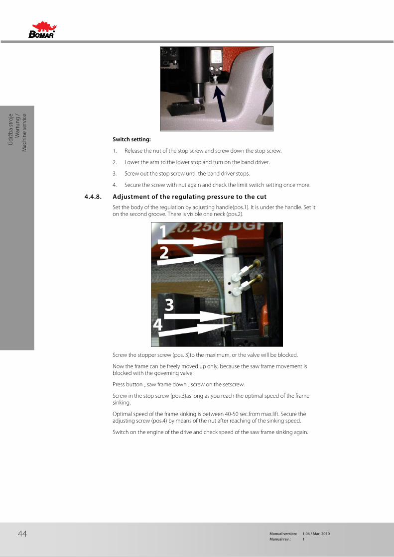
Switch setting:
1. Release the nut of the stop screw and screw down the stop screw.
2. Lower the arm to the lower stop and turn on the band driver.
3. Screw out the stop screw until the band driver stops.
4. Secure the screw with nut again and check the limit switch setting once more.
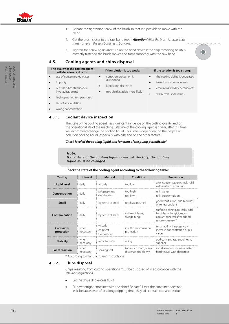
4.4.8. Adjustment of the regulating pressure to the cut
Set the body of the regulation by adjusting handle(pos.1). It is under the handle. Set it on the second groove. There is visible one neck (pos.2).
Screw the stopper screw (pos. 3)to the maximum, or the valve will be blocked.
Now the frame can be freely moved up only, because the saw frame movement is blocked with the governing valve.
Press button „ saw frame down „ screw on the setscrew.
Screw in the stop screw (pos.3)as long as you reach the optimal speed of the frame sinking.
Optimal speed of the frame sinking is between 40-50 sec.from max.lift. Secure the adjusting screw (pos.4) by means of the nut after reaching of the sinking speed.
Switch on the engine of the drive and check speed of the saw frame sinking again.

45
Údržba stroje
Wartung
Machine service
4.4.9. Adjustment of a throttle valve
Switch off the machine by its main switch. Let the sawing head down at the bottom. Close the throttle valve gently.
A B
The worm screw (pos. A) must be next to the stop (pos. B), when the valve is closed.
Otherwise, you must loosen the worm screw, lift the plastic knob and close the throttle valve to the maximum. Next loosen the worm screw and take off the plastic knob. Put it back so that the worm screw must be next to the stop while the valve is closed. Then tighten the worm screw again.
Turn the machine on and test the down-feed control.
4.4.10. Brush adjustment
The brush has essential influence on cutting performance, saw band lifetime and lifetime of wheels and hard metal guides and finally cut accuracy. Therefore the brush has to be checked during every shift.
46 Manual version: 1.04 / Mar. 2010Manual rev.: 1
Údr
žba
stro
je
War
tung
/
Mac
hine
ser
vice
1. Release the tightening screw of the brush so that it is possible to move with the brush.
2. Get the brush closer to the saw band teeth. Attention! After the brush is set, its ends must not reach the saw band teeth bottoms.
3. Tighten the screw again and turn on the band driver. If the chip removing brush is correctly fastened the brush moves and turns smoothly with the saw band.
4.5. Cooling agents and chips disposal
The quality of the cooling agent will deteriorate due to: If the solution is too weak: If the solution is too strong:
• use of contaminated water
• impurity
• outside oil contamination (hydraulics, gears)
• high operating temperatures
• lack of air circulation
• wrong concentration
• corrosion protection is diminished
• lubrication decreases
• microbial attack is more likely
• the cooling ability is decreased
• foam behaviour increases
• emulsions stability deteriorates
• sticky residue develops
4.5.1. Coolant device inspection
The state of the cooling agent has significant influence on the cutting quality and on the operational life of the machine. Lifetime of the cooling liquid is 1 year, after this time we recommend change the cooling liquid. This time is dependent on the degree of pollution cooling liquid (especially with oils) and on the other factors.
Check level of the cooling liquid and function of the pump periodically!
Check the state of the cooling agent according to the following table:
Testing Interval Method Condition Precaution
Liquid level daily visually too low after concentration check, refill with water or emulsion
Concentration daily refractometer densimeter
too high too low
refill water refill base emulsion
Smell daily by sense of smell unpleasant smell good ventilation, add biocides or renew coolant
Contamination daily by sense of smell visible oil leaks, sludge fungi
surface cleaning, fix leaks, add biocides or fungicides, or coolant renewal after added system cleanser*
Corrosion-protection
when necessary
visually chip test Herbert-test
insufficient corrosion protection
test stability, if necessary – increase concentration or pH value
Stability when necessary
refractometer oiling add concentrate, enquiries to supplier
Foam reaction when necessary shaking test
too much foam, foam disperses too slowly
avoid aeration, increase water hardness, ix with defoamer
* According to manufacturers’ instructions
4.5.2. Chips disposal
Chips resulting from cutting operations must be disposed of in accordance with the relevant regulations.
• Let the chips drip excess fluid!.
• Fill a watertight container with the chips! Be careful that the container does not leak, because even after a long dripping time, they still contain coolant residue.
Note: I f the state of the cooling l iquid is not satisfactory, the cooling l iquid must be changed.
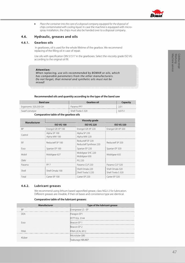
47
Údržba stroje
Wartung
Machine service
• Place the container into the care of a disposal company equipped for the disposal of chips contaminated with cooling liquid. In case the machine is equipped with micro-spray installation, the chips must also be handed over to a disposal company.
4.6. Hydraulic, greases and oils
4.6.1. Gearbox oils
In gearboxes, oil is used for the whole lifetime of the gearbox. We recommend replacing of the filling oil in case of repair.
Use oils with specification DIN 51517 in the gearboxes. Select the viscosity grade ISO VG according to the original oil fill.
Recommended oils and quantity according to the type of the band saw
Band saw Gearbox oil Capacity
Ergonomic 320.250 GH Paramo PP7 2,0 l
Swarf conveyor Shell Tivela S 320 0,075 l
Comparative table of the gearbox oils
Manufacturer Viscosity grade
ISO VG 100 ISO VG 220 ISO VG 320
BP Energol GR-XP 100 Energol GR-XP 220 Energol GR-XP 320
Castrol Alpha SP 100 Alpha MW 100
Alpha SP 220 Alpha MW 220
Elf Reductelf SP 100 Reductelf SP 220 Reductelf Synthese 220
Reductelf SP 320
Esso Spartan EP 100 Spartan EP 220 Spartan EP 320
Mobil Mobilgear 627 Mobilgear SHC 220 Mobilgear 630
Mobilgear 632
ÖMV PG 220
Paramo PP 7 Paramo CLP 220 Paramo CLP 320
Shell Shell Omala 100 Shell Omala 220 Shell Tivela S 220
Shell Omala 320 Shell Tivela S 320
Total Carter EP 100 Carter EP 220 Carter EP 320
4.6.2. Lubricant greases
We recommend using lithium based saponified grease, class NGLI-2 for lubrication. Different greases are mixable, if their oil bases and consistence type are identical.
Comparative table of the lubricant greases:
Manufacturer Type of the lubricant grease
BP Energrease LS - EP
DEA Paragon EP1
Esso
FETT EGL 3144
Beacon EP 1
Beacon EP 2
FINA FINA LICAL M12
Klüber Microlube GB0
Staburags NBU8EP
Attention: When replacing, use oils recommended by BOMAR or oils , which has comparable parameters from the other manufacturers. Do not forget, that mineral and synthetic oils must not be mixed!
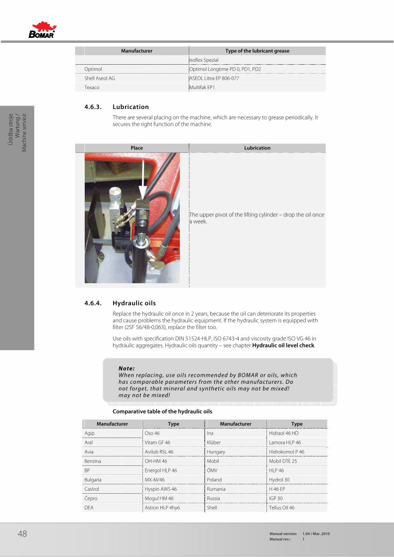
48 Manual version: 1.04 / Mar. 2010Manual rev.: 1
Údr
žba
stro
je
War
tung
/
Mac
hine
ser
vice
Manufacturer Type of the lubricant grease
Isoflex Spezial
Optimol Optimol Longtime PD 0, PD1, PD2
Shell Aseol AG ASEOL Litea EP 806-077
Texaco Multifak EP1
4.6.3. Lubrication
There are several placing on the machine, which are necessary to grease periodically. It secures the right function of the machine.
Place Lubrication
The upper pivot of the lifting cylinder – drop the oil once a week.
4.6.4. Hydraulic oils
Replace the hydraulic oil once in 2 years, because the oil can deteriorate its properties and cause problems the hydraulic equipment. If the hydraulic system is equipped with filter (2SF 56/48-0,063), replace the filter too.
Use oils with specification DIN 51524-HLP, ISO 6743-4 and viscosity grade ISO VG 46 in hydraulic aggregates. Hydraulic oils quantity – see chapter Hydraulic oil level check.
Comparative table of the hydraulic oils
Manufacturer Type Manufacturer Type
Agip Oso 46 Ina Hidraol 46 HD
Aral Vitam GF 46 Klüber Lamora HLP 46
Avia Avilub RSL 46 Hungary Hidrokomol P 46
Benzina OH-HM 46 Mobil Mobil DTE 25
BP Energol HLP 46 ÖMV HLP 46
Bulgaria MX-M/46 Poland Hydrol 30
Castrol Hyspin AWS 46 Rumania H 46 EP
Čepro Mogul HM 46 Russia IGP 30
DEA Astron HLP 4hy6 Shell Tellus Oil 46
Note: When replacing, use oils recommended by BOMAR or oils , which has comparable parameters from the other manufacturers. Do not forget, that mineral and synthetic oils may not be mixed! may not be mixed!
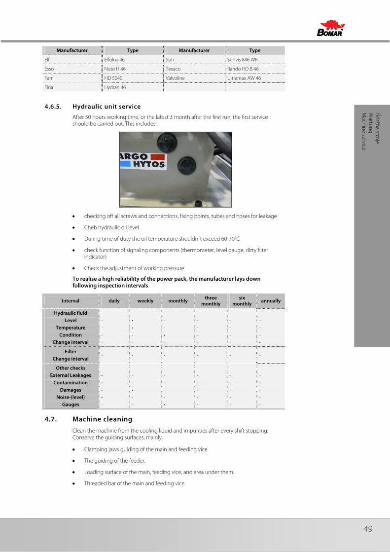
49
Údržba stroje
Wartung
Machine service
Manufacturer Type Manufacturer Type
Elf Elfolna 46 Sun Sunvis 846 WR
Esso Nuto H 46 Texaco Rando HD B 46
Fam HD 5040 Valvoline Ultramax AW 46
Fina Hydran 46
4.6.5. Hydraulic unit service
After 50 hours working time, or the latest 3 month after the first run, the first service should be carried out. This includes:
• checking off all screws and connections, fixing points, tubes and hoses for leakage
• Cheb hydraulic oil level
• During time of duty the oil temperature shouldn´t exceed 60-70°C
• check function of signaling components (thermometer, level gauge, dirty filter indicator)
• Check the adjustment of working pressure
To realise a high reliability of the power pack, the manufacturer lays down following inspection intervals
Interval daily weekly monthly three
monthly six
monthly annually
Hydraulic fluid Level
Temperature Condition
Change interval
- - - -
• • - -
- - • -
- - - -
- - - -
- - - •
Filter Change interval
- - - - - -
Other checks External Leakages
Contamination Damages
Noise-(level) Gauges
• • • • -
- - • - -
- - - - •
- - - - -
- - - - -
- - - - -
4.7. Machine cleaning
Clean the machine from the cooling liquid and impurities after every shift stopping. Conserve the guiding surfaces, mainly.
• Clamping jaws guiding of the main and feeding vice.
• The guiding of the feeder.
• Loading surface of the main, feeding vice, and area under them.
• Threaded bar of the main and feeding vice.
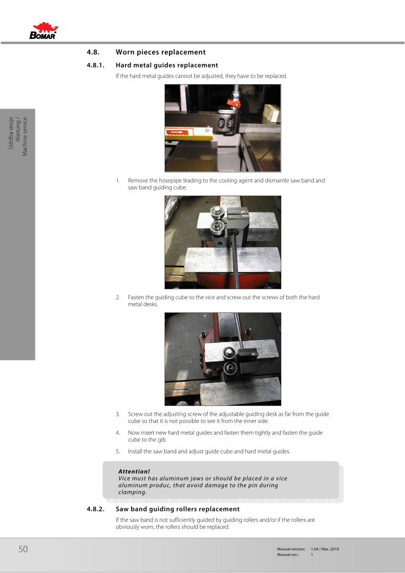
50 Manual version: 1.04 / Mar. 2010Manual rev.: 1
Údr
žba
stro
je
War
tung
/
Mac
hine
ser
vice
4.8. Worn pieces replacement
4.8.1. Hard metal guides replacement
If the hard metal guides cannot be adjusted, they have to be replaced.
1. Remove the hosepipe leading to the cooling agent and dismantle saw band and saw band guiding cube.
2. Fasten the guiding cube to the vice and screw out the screws of both the hard metal desks.
3. Screw out the adjusting screw of the adjustable guiding desk as far from the guide cube so that it is not possible to see it from the inner side.
4. Now insert new hard metal guides and fasten them tightly and fasten the guide cube to the gib.
5. Install the saw band and adjust guide cube and hard metal guides.
4.8.2. Saw band guiding rollers replacement
If the saw band is not sufficiently guided by guiding rollers and/or if the rollers are obviously worn, the rollers should be replaced.
Attention! Vice must has aluminum jaws or should be placed in a vice aluminum produc, that avoid damage to the pin during clamping.

51
Údržba stroje
Wartung
Machine service
Attention! Guiding rollers must be replaced together on both guide cubes!
1. Remove the hosepipe leading to the cooling agent and dismantle saw band and saw band guide cube.
2. Grip the guide cube in the vice and screw out both fastening screws of the eccentrics.
3. Pull both guide rollers from their eccentrics.
4. Put new guide rollers on the eccentrics and screw the eccentrics to the guide cube.
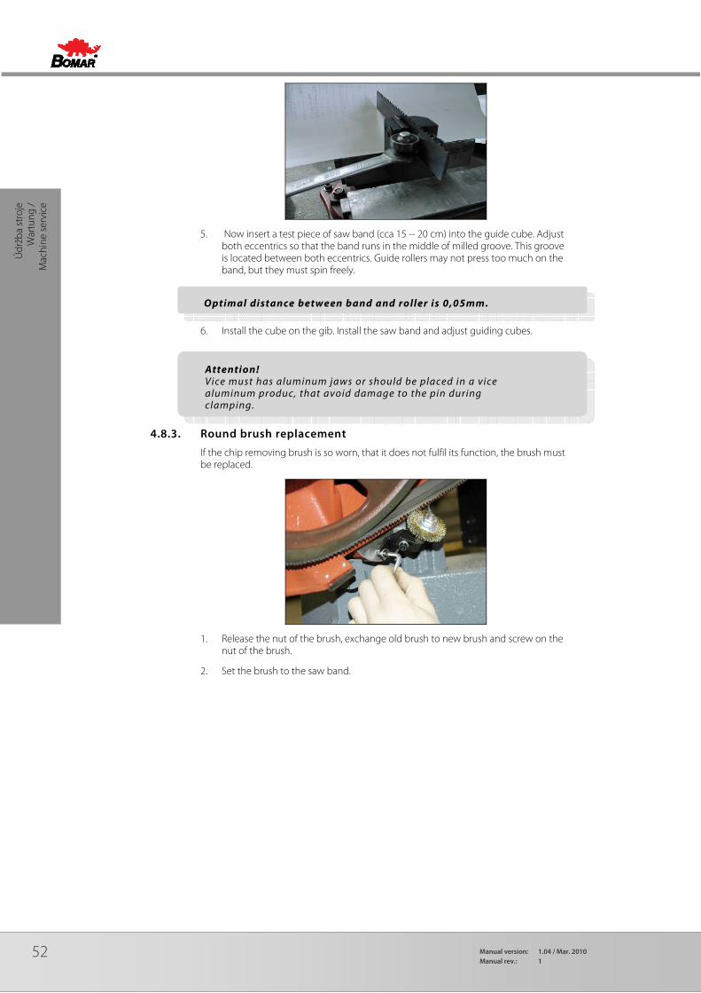
52 Manual version: 1.04 / Mar. 2010Manual rev.: 1
Údr
žba
stro
je
War
tung
/
Mac
hine
ser
vice
5. Now insert a test piece of saw band (cca 15 -- 20 cm) into the guide cube. Adjust both eccentrics so that the band runs in the middle of milled groove. This groove is located between both eccentrics. Guide rollers may not press too much on the band, but they must spin freely.
6. Install the cube on the gib. Install the saw band and adjust guiding cubes.
4.8.3. Round brush replacement
If the chip removing brush is so worn, that it does not fulfil its function, the brush must be replaced.
1. Release the nut of the brush, exchange old brush to new brush and screw on the nut of the brush.
2. Set the brush to the saw band.
Attention! Vice must has aluminum jaws or should be placed in a vice aluminum produc, that avoid damage to the pin during clamping.
Optimal distance between band and roller is 0,05mm.
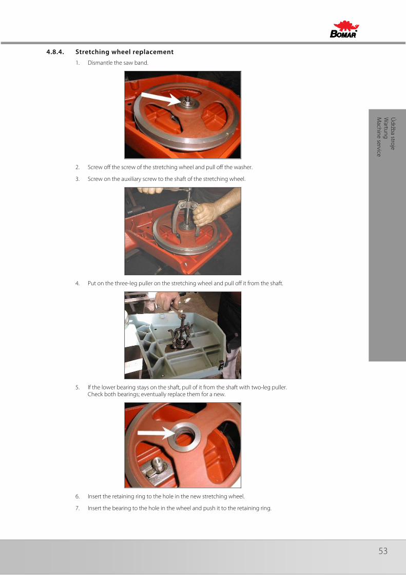
53
Údržba stroje
Wartung
Machine service
4.8.4. Stretching wheel replacement
1. Dismantle the saw band.
2. Screw off the screw of the stretching wheel and pull off the washer.
3. Screw on the auxiliary screw to the shaft of the stretching wheel.
4. Put on the three-leg puller on the stretching wheel and pull off it from the shaft.
5. If the lower bearing stays on the shaft, pull of it from the shaft with two-leg puller. Check both bearings; eventually replace them for a new.
6. Insert the retaining ring to the hole in the new stretching wheel.
7. Insert the bearing to the hole in the wheel and push it to the retaining ring.
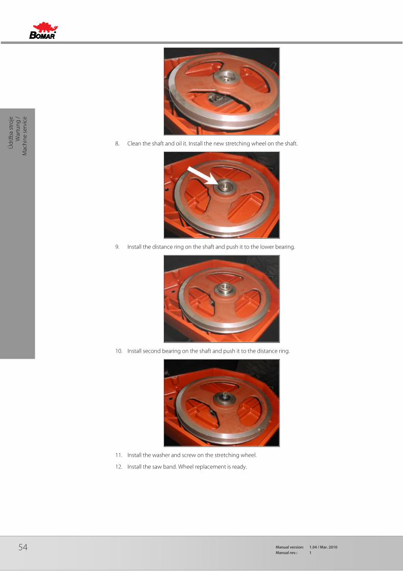
54 Manual version: 1.04 / Mar. 2010Manual rev.: 1
Údr
žba
stro
je
War
tung
/
Mac
hine
ser
vice
8. Clean the shaft and oil it. Install the new stretching wheel on the shaft.
9. Install the distance ring on the shaft and push it to the lower bearing.
10. Install second bearing on the shaft and push it to the distance ring.
11. Install the washer and screw on the stretching wheel.
12. Install the saw band. Wheel replacement is ready.
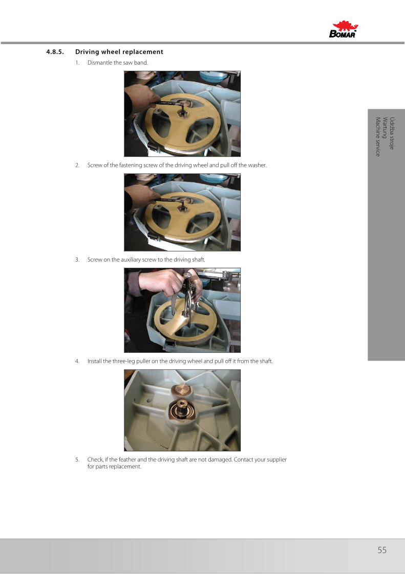
55
Údržba stroje
Wartung
Machine service
4.8.5. Driving wheel replacement
1. Dismantle the saw band.
2. Screw of the fastening screw of the driving wheel and pull off the washer.
3. Screw on the auxiliary screw to the driving shaft.
4. Install the three-leg puller on the driving wheel and pull off it from the shaft.
5. Check, if the feather and the driving shaft are not damaged. Contact your supplier for parts replacement.
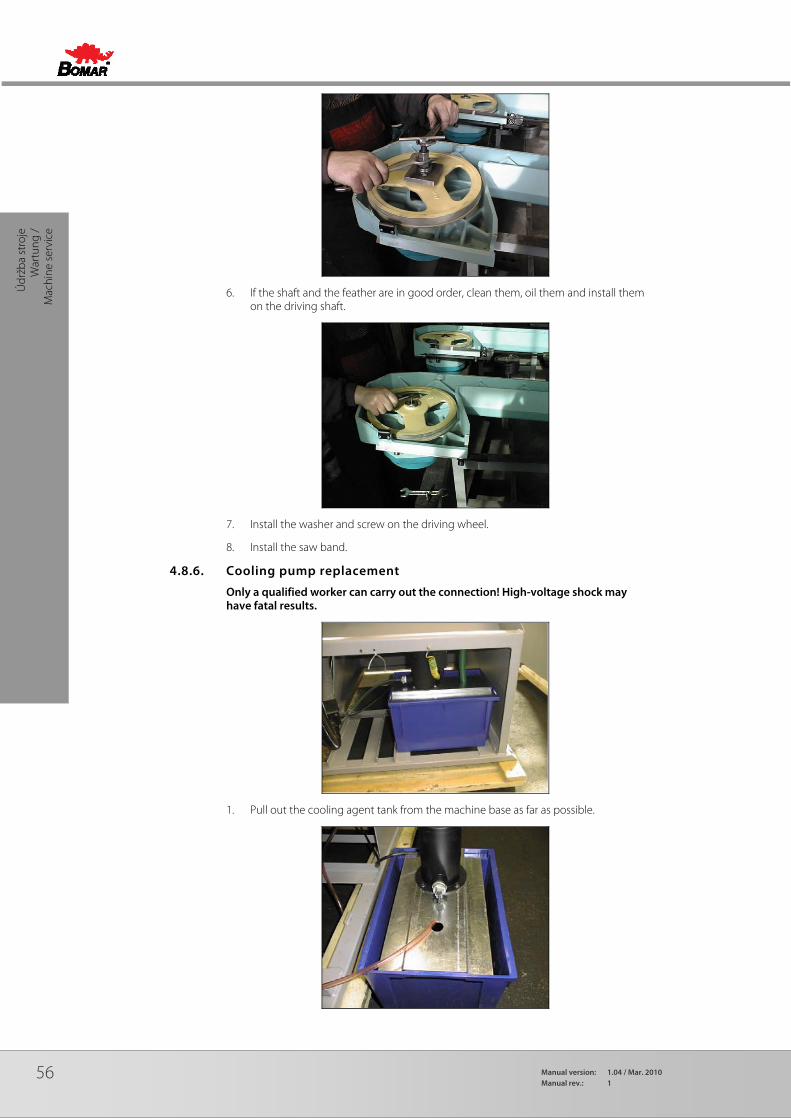
56 Manual version: 1.04 / Mar. 2010Manual rev.: 1
Údr
žba
stro
je
War
tung
/
Mac
hine
ser
vice
6. If the shaft and the feather are in good order, clean them, oil them and install them on the driving shaft.
7. Install the washer and screw on the driving wheel.
8. Install the saw band.
4.8.6. Cooling pump replacement
Only a qualified worker can carry out the connection! High-voltage shock may have fatal results.
1. Pull out the cooling agent tank from the machine base as far as possible.

57
Údržba stroje
Wartung
Machine service
2. Remove the hosepipe leading the cooling agent from the connection on the pump. Unscrew four screws on the cooling pump flange and pull out the pump from the metal sheet holder.
3. Remove the cover of the pump terminal switchboard. Disconnect 4 terminal connectors of the input cables. Cables are identified according to the red clamps.
4. Loosen the bushing and pull the cable out from the pump.
5. Dismantle new pump switchboard cover. Push the cable through the bushing and fasten it.

58 Manual version: 1.04 / Mar. 2010Manual rev.: 1
Záva
dy
Trou
bles
hoot
ing

59
Závady Troubleshooting
5. Závady / Troubleshooting
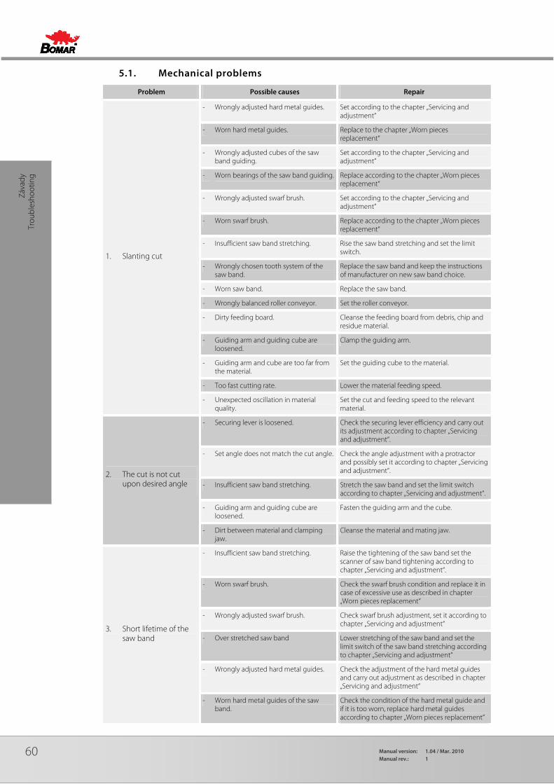
60 Manual version: 1.04 / Mar. 2010Manual rev.: 1
Záva
dy
Trou
bles
hoot
ing
5.1. Mechanical problems
Problem Possible causes Repair
1. Slanting cut
- Wrongly adjusted hard metal guides. Set according to the chapter „Servicing and adjustment“
- Worn hard metal guides. Replace to the chapter „Worn pieces replacement“
- Wrongly adjusted cubes of the saw band guiding.
Set according to the chapter „Servicing and adjustment“
- Worn bearings of the saw band guiding. Replace according to the chapter „Worn pieces replacement“
- Wrongly adjusted swarf brush. Set according to the chapter „Servicing and adjustment“
- Worn swarf brush. Replace according to the chapter „Worn pieces replacement“
- Insufficient saw band stretching. Rise the saw band stretching and set the limit switch.
- Wrongly chosen tooth system of the saw band.
Replace the saw band and keep the instructions of manufacturer on new saw band choice.
- Worn saw band. Replace the saw band.
- Wrongly balanced roller conveyor. Set the roller conveyor.
- Dirty feeding board. Cleanse the feeding board from debris, chip and residue material.
- Guiding arm and guiding cube are loosened.
Clamp the guiding arm.
- Guiding arm and cube are too far from the material.
Set the guiding cube to the material.
- Too fast cutting rate. Lower the material feeding speed.
- Unexpected oscillation in material quality.
Set the cut and feeding speed to the relevant material.
2. The cut is not cut upon desired angle
- Securing lever is loosened. Check the securing lever efficiency and carry out its adjustment according to chapter „Servicing and adjustment“.
- Set angle does not match the cut angle. Check the angle adjustment with a protractor and possibly set it according to chapter „Servicing and adjustment“.
- Insufficient saw band stretching. Stretch the saw band and set the limit switch according to chapter „Servicing and adjustment“.
- Guiding arm and guiding cube are loosened.
Fasten the guiding arm and the cube.
- Dirt between material and clamping jaw.
Cleanse the material and mating jaw.
3. Short lifetime of the saw band
- Insufficient saw band stretching. Raise the tightening of the saw band set the scanner of saw band tightening according to chapter „Servicing and adjustment“.
- Worn swarf brush. Check the swarf brush condition and replace it in case of excessive use as described in chapter „Worn pieces replacement“
- Wrongly adjusted swarf brush. Check swarf brush adjustment, set it according to chapter „Servicing and adjustment“
- Over stretched saw band Lower stretching of the saw band and set the limit switch of the saw band stretching according to chapter „Servicing and adjustment“
- Wrongly adjusted hard metal guides. Check the adjustment of the hard metal guides and carry out adjustment as described in chapter „Servicing and adjustment“
- Worn hard metal guides of the saw band.
Check the condition of the hard metal guide and if it is too worn, replace hard metal guides according to chapter „Worn pieces replacement“
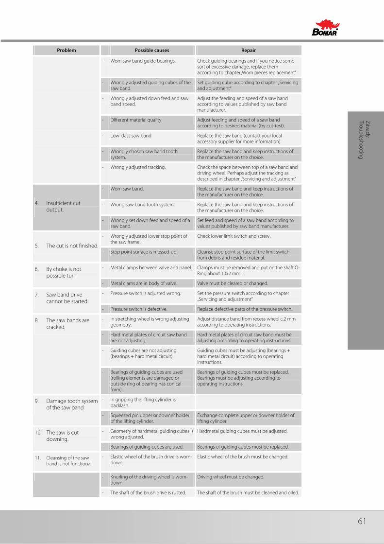
61
Závady Troubleshooting
Problem Possible causes Repair
- Worn saw band guide bearings. Check guiding bearings and if you notice some sort of excessive damage, replace them according to chapter„Worn pieces replacement“
- Wrongly adjusted guiding cubes of the saw band.
Set guiding cube according to chapter „Servicing and adjustment“
- Wrongly adjusted down feed and saw band speed.
Adjust the feeding and speed of a saw band according to values published by saw band manufacturer.
- Different material quality. Adjust feeding and speed of a saw band according to desired material (try cut-test).
- Low-class saw band Replace the saw band (contact your local accessory supplier for more information)
- Wrongly chosen saw band tooth system.
Replace the saw band and keep instructions of the manufacturer on the choice.
- Wrongly adjusted tracking. Check the space between top of a saw band and driving wheel. Perhaps adjust the tracking as described in chapter „Servicing and adjustment“
4. Insufficient cut output.
- Worn saw band. Replace the saw band and keep instructions of the manufacturer on the choice.
- Wrong saw band tooth system. Replace the saw band and keep instructions of the manufacturer on the choice.
- Wrongly set down feed and speed of a saw band.
Set feed and speed of a saw band according to values published by saw band manufacturer.
5. The cut is not finished.
- Wrongly adjusted lower stop point of the saw frame.
Check lower limit switch and screw.
- Stop point surface is messed-up. Cleanse stop point surface of the limit switch from debris and residue material.
6. By choke is not possible turn
- Metal clamps between valve and panel. Clamps must be removed and put on the shaft O-Ring about 10x2 mm.
- Metal clams are in body of valve. Valve must be cleared or changed.
7. Saw band drive cannot be started.
- Pressure switch is adjusted wrong. Set the pressure switch according to chapter „Servicing and adjustment“
- Pressure switch is defective. Replace defective parts of the pressure switch.
8. The saw bands are cracked.
- In stretching wheel is wrong adjusting geometry.
Adjust distance band from recess wheel c.2 mm according to operating instructions.
- Hard metal plates of circuit saw band are not adjusting.
Hard metal plates of circuit saw band must be adjusting according to operating instructions.
- Guiding cubes are not adjusting (bearings + hard metal circuit)
Guiding cubes must be adjusting (bearings + hard metal circuit) according to operating instructions.
- Bearings of guiding cubes are used (rolling elements are damaged or outside ring of bearing has conical form).
Bearings of guiding cubes must be replaced. Bearings must be adjusting according to operating instructions.
9. Damage tooth system of the saw band
- In gripping the lifting cylinder is backlash.
- Squeezed pin upper or downer holder of the lifting cylinder.
Exchange complete upper or downer holder of lifting cylinder.
10. The saw is cut downing.
- Geometry of hardmetal guiding cubes is wrong adjusted.
Hardmetal guiding cubes must be adjusted.
- Bearings of guiding cubes are used. Bearings of guiding cubes must be replaced.
11. Cleansing of the saw band is not functional.
- Elastic wheel of the brush drive is worn-down.
Elastic wheel of the brush must be changed.
- Knurling of the driving wheel is worn-down.
Driving wheel must be changed.
- The shaft of the brush drive is rusted. The shaft of the brush must be cleaned and oiled.
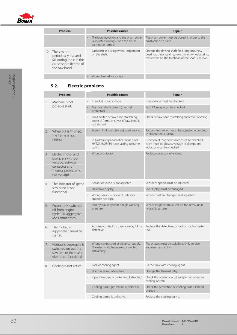
62 Manual version: 1.04 / Mar. 2010Manual rev.: 1
Záva
dy
Trou
bles
hoot
ing
Problem Possible causes Repair
- The brush position and the brush cover is adjusted wrong – with the brush cannot be turned.
The brush cover must be posed, in order to the brush can be turned.
12. The saw arm periodically rise and fall during the cut; this cause short lifetime of the saw band.
- Backslash in driving wheel lodgement on the shaft.
Change the driving shaft for a long one, new bearings, distance ring, new driving wheel, spring, two covers on the forehead of the shaft + screws.
- Worn channel for spring.
5.2. Electric problems
Problem Possible causes Repair
1. Machine is not possible start.
- In socket is not voltage Line voltage must be checked.
- Transfer relay is closed (thermal protector)
Each FA relay must be checked.
- Limit switch of saw band stretching, cover of frame or cover of saw band is not started.
Check of saw band stretching and covers closing.
2. When cut is finished, the frame is not raising.
- Bottom limit switch is adjusted wrong. Bottom limit switch must be adjusted according to chapter ADJUSTING.
- In hydraulic (pneumatic) ring is error. HYTOS (BOSCH) is not acting to frame uplift.
Function of magnetic valve must be checked, valve must be closed, voltage of clamps and inductor must be checked.
3. Electric motor and pump are without voltage. Between contactor and thermal protector is not voltage.
- Wrong contactor. Replace contactor of engine.
4. The indicator of speed saw band is not functional.
- Sensor of speed is not adjusted. Sensor of speed must be adjusted.
- Defective display The display must be changed.
- Wrong sensor – diode of indicator speed is not light.
Sensor must be changed and adjusted.
5. Protector is switched off from engine hydraulic aggregate MA3 sometimes.
- Into hydraulic system is high working pressure.
Service engineer must reduce the pressure in hydraulic system.
6. The hydraulic aggregate cannot be started
Auxiliary contact on thermo-relay FA1 is defective.
Replace the defective contact on motor starter FA1.
7. Hydraulic aggregate is switched on but the saw arm or the main vice is not functional
- Wrong connection of electrical supply. The electrical phases are connected conversely.
The phases must be switched. Only service engineer can do this.
8. Cooling is not active Lack of cooling agent. Fill the tank with cooling agent.
- Thermal relay is defective Change the thermal relay
- Input hosepipe is broken or obstructed. Check the cooling circuit and perhaps cleanse cooling system.
- Cooling pump protection is defective Check the protection of cooling pump if need change it.
- Cooling pump is defective. Replace the cooling pump.

63
Závady Troubleshooting
5.3. Hydraulic problems
Problem Possible causes Repair
1. Hydrogenerator not supplying oil
• reverse rotation Check the connections of each phase. Reconnect properly connection of the electrical phases.
• shortage of oil in the tank Add hydraulic oil
• Oil viscosity does not correspond prescribed viscosity value
Change hydraulic oil.
• Hydrogenerator malfunction Call service
• Wrong power supply connection. Check the connections of each phase. Reconnect properly connection of the electrical phases.
2. Hydraulic oil contains bubbles
• Hydraulic circuit is not adequately deaerated
Make deaeration of hydraulic circuit.
• Low oil level Add hydraulic oil
• the pump shaft seals damaged Call service
3. Increased mechanical noise
• damaged joint drive Call service
• damaged or destroyed motor bearings Call service
• air intake Check for leaks.
4. Low pressure, pump supplies oil
• problem in the safety valve Wrong settings. Check the settings and adjust the safety valve.
• pump wear Call service
• external or internal leakage Call service
5. Hydrogenerator is seized
• damage by solid particles in oil Make oil filtration, or call the service.
• non-prescribed oil Change hydraulic oil.
• wrong type of oil Change hydraulic oil.
• exceeding the life of the pump Call service
6. Overheating oil • cooler malfunction Check the cooler function or call service.
• wear the pump, the energy is converted into heat
Call service
7. Hydraulic valve can not be readjusted
• electromagnet has no signal (voltage) - interrupted supply lines
Check again.
• Electromagnet coil burnt Replace coil – Call service.
• spool valve sticking Replace valve – Call service

64 Manual version: 1.04 / Mar. 2010Manual rev.: 1
Sché
mat
a Sc
hem
as
Sche
mat
ics

65
Schémata
Schemas
Schematics
6. Schémata / Schemas / Schematics
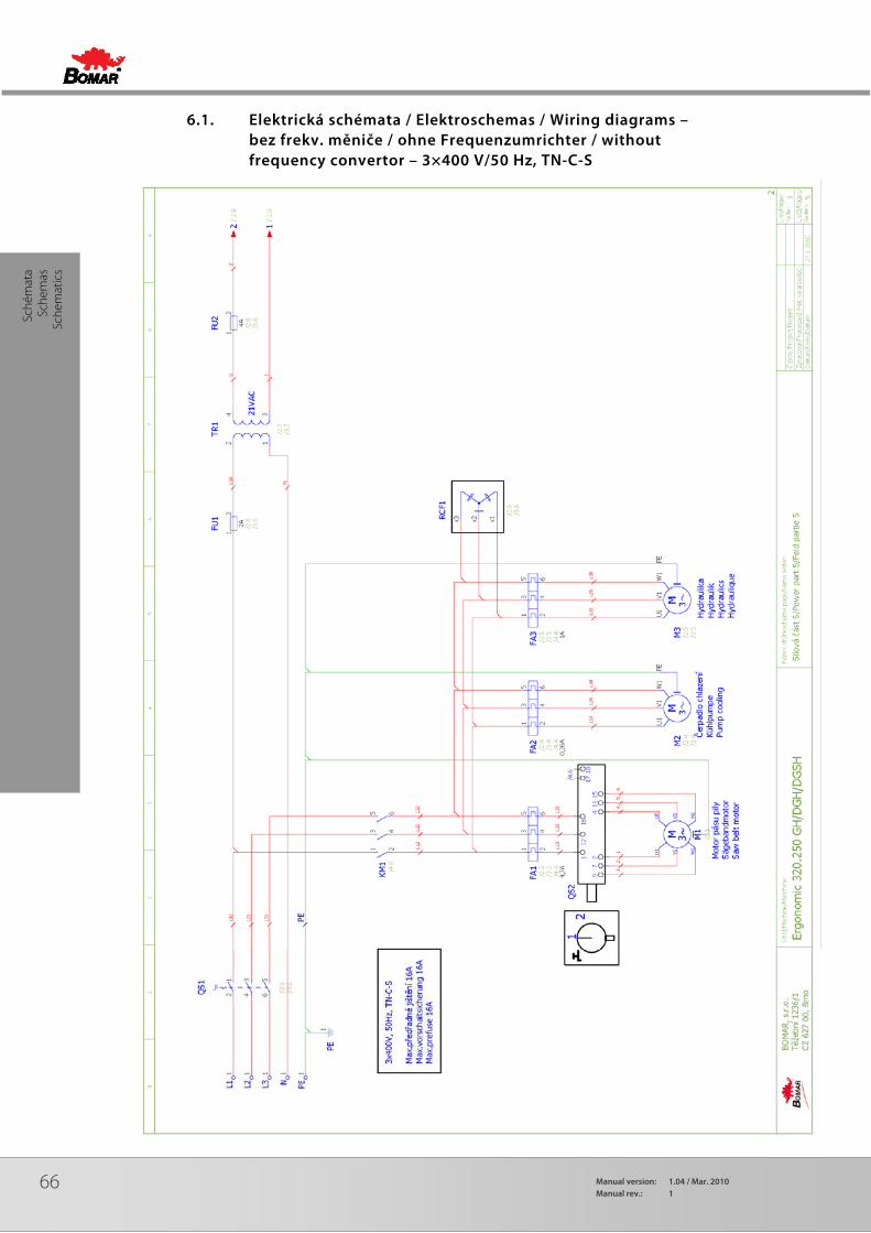
66 Manual version: 1.04 / Mar. 2010Manual rev.: 1
Sché
mat
a Sc
hem
as
Sche
mat
ics
6.1. Elektrická schémata / Elektroschemas / Wiring diagrams – bez frekv. měniče / ohne Frequenzumrichter / without frequency convertor – 3×400 V/50 Hz, TN-C-S
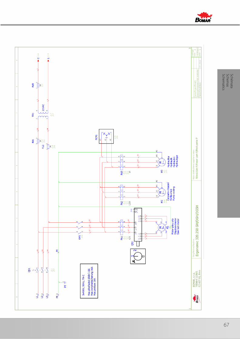
67
Schémata
Schemas
Schematics
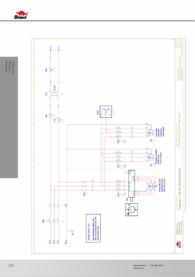
68 Manual version: 1.04 / Mar. 2010Manual rev.: 1
Sché
mat
a Sc
hem
as
Sche
mat
ics
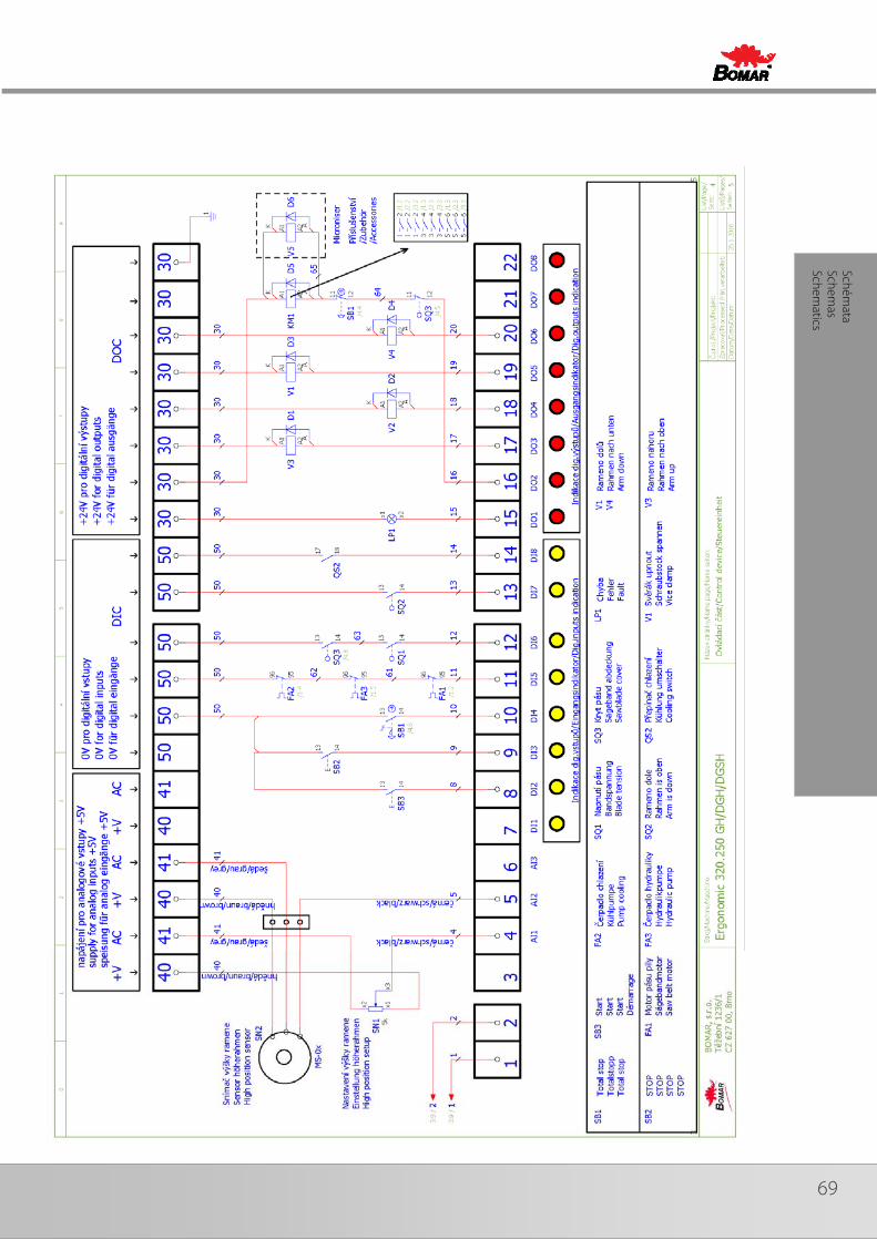
69
Schémata
Schemas
Schematics
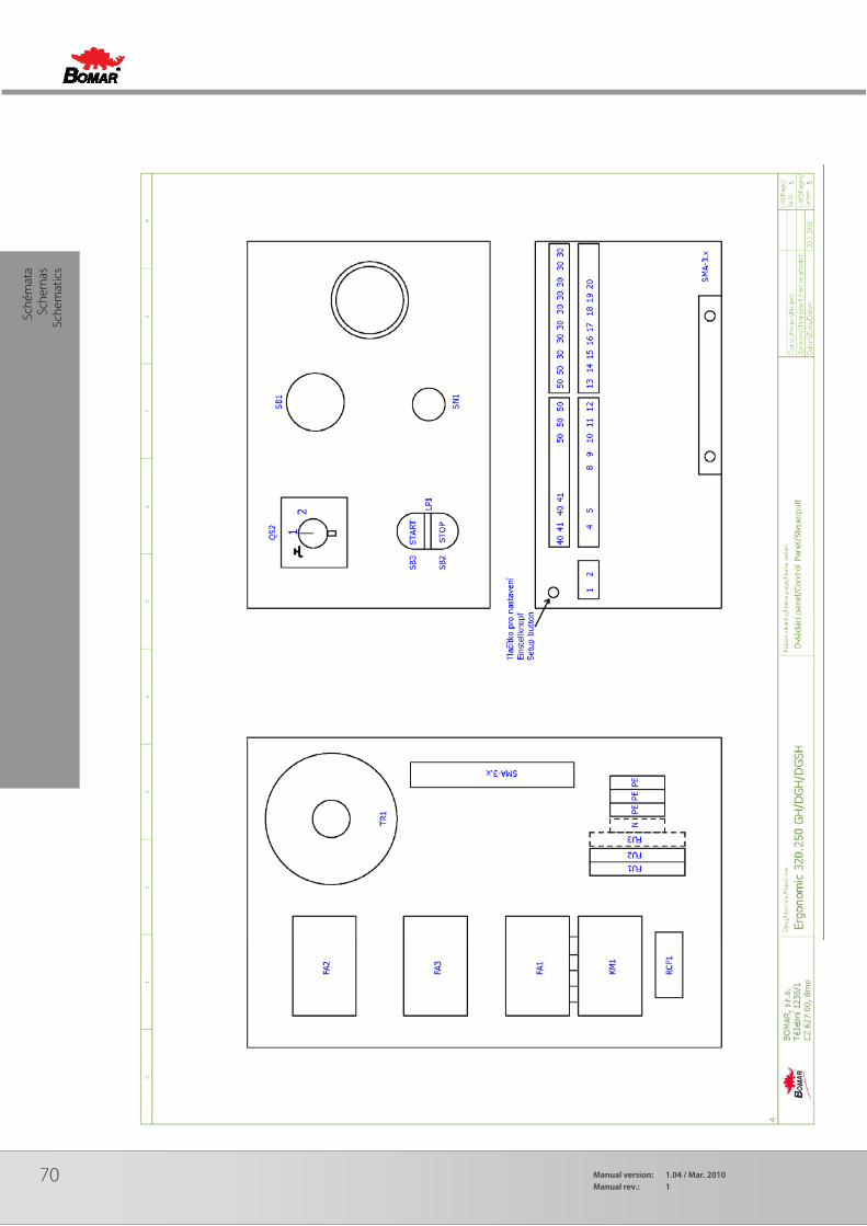
70 Manual version: 1.04 / Mar. 2010Manual rev.: 1
Sché
mat
a Sc
hem
as
Sche
mat
ics

71
Schémata
Schemas
Schematics
6.2. Elektrické schema /Elektroschema /Wiring diagrams – frekv. měnič / Frequenzumrichter / Frequency convertor – 3×400 V/50 Hz, TN-C-S
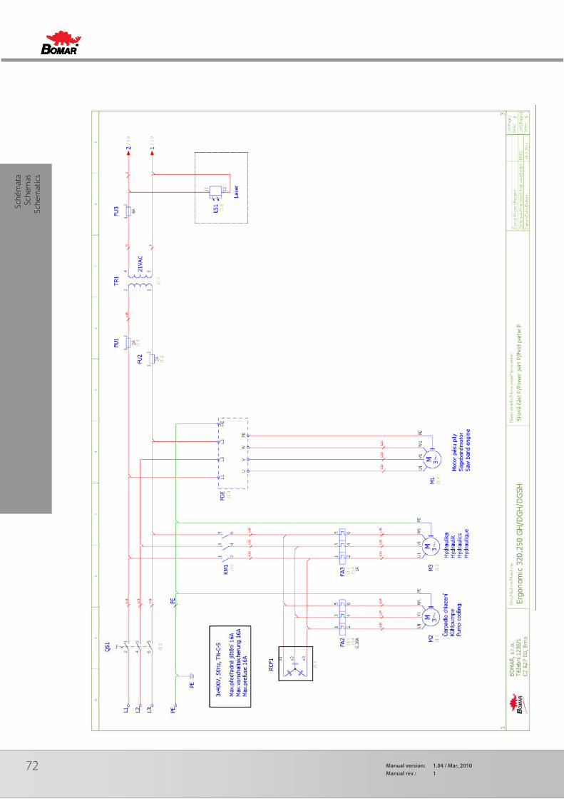
72 Manual version: 1.04 / Mar. 2010Manual rev.: 1
Sché
mat
a Sc
hem
as
Sche
mat
ics

73
Schémata
Schemas
Schematics
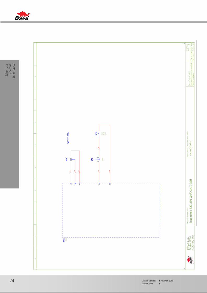
74 Manual version: 1.04 / Mar. 2010Manual rev.: 1
Sché
mat
a Sc
hem
as
Sche
mat
ics
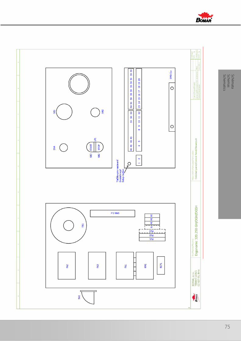
75
Schémata
Schemas
Schematics

76 Manual version: 1.04 / Mar. 2010Manual rev.: 1
Sché
mat
a Sc
hem
as
Sche
mat
ics
6.3. Hydraulické schéma / Hydraulikschema Hydraulic diagrams

77
Schémata
Schemas
Schematics
Poz. Pos. Pos.
Název Bezeichnung
Item Typ Hytos Typ Hykom
Ks Mng. Pcs.
1 Nádrž / Behälter / Tank 12 dm 3 VÁLCOVÁ ,PLECH
1
2 Elektromotor / Elektromotor / Electromotor
M A -A L71 0,25k W 400/230V ,50H z
1
3 Hydrogenerátor / Hydraulikgenerator / Hydrogenerator
P 2-3,3L.65017 3,3 cm3/ot. 1
4 Jednosměrný ventil / Einwegventil / One-way valve
V JZH -06-005-G 1/4
1
5 Přepouštěcí ventil / Bypaßventil / By pass valve
V P P 2-04/S -6 Set on 3 MPa 1
6 Sací filtr / Filter / Suction filter 2S F 56/48-0,063 63 μm 1
7 Rozvaděč / Verteilungsventil / Distributor
R P E K 1-03G 2R 11/02400E 1K 1
M D1L-TA /10N-D24K 1
24V DC 1
8 Rozvaděč / Verteilungsventil / Distributor
R P E K 1-03G 3Z11/02400E 1K 1Z2
M D1L-S 1/10N-D24K 1
24V DC 1
9 Nalévací zátka / Einfüllspund / Fill stopper
L1.0406-101 1
10 Stop Ventil / Stop-Ventil / Stop Valve
555-0607 92.153.013 1
11 RE G ULA CE K O S TK A : 251.218 1
12 Válec zvedací / Hebezylinder / Lifting cylinder
D40/D20-130 2-ČINNÝ 1
13 Válec svěráku / Schraubstockzylinder / Vice cylinder
D50/D24-6 1-ČINNÝ 1

78 Manual version: 1.04 / Mar. 2010Manual rev.: 1
79
7. Výkresy sestav pro objednání náhradních dílů / Zeichnungen für Bestellung der Ersatzteile / Drawing assemblies for spare parts order
• Při objednávání náhradních dílů vždy uvádějte: typ stroje (např. practix Ergonomic 320.250 GH) , výrobní číslo (např. 125) a rok výroby (např. 1999).
• In die Bestellung der Ersatzteile führen Sie immer an: Maschinentyp (z. B. Ergonomic 320.250 GH), Serien Nr. (z. B. 125) und Baujahr (z. B. 1999).
• For spare parts order, you must always to allege: type of machine (for example Ergonomic 320.250 GH), serial number (for example 125, see cover page) and year of construction (for example 1999).

80 Manual version: 1.04 / Mar. 2010Manual rev.: 1
7.1. Ergonomic 320.250 GH
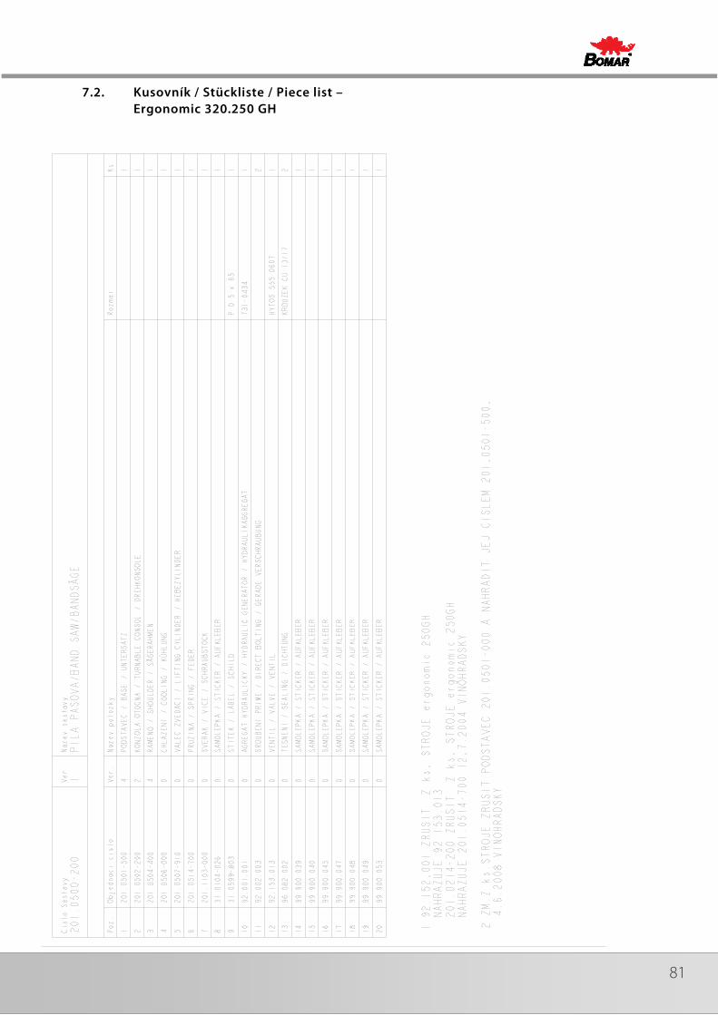
81
7.2. Kusovník / Stückliste / Piece list – Ergonomic 320.250 GH
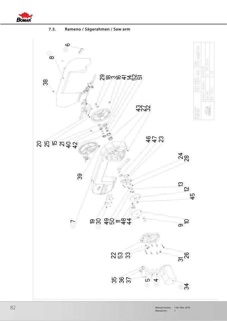
82 Manual version: 1.04 / Mar. 2010Manual rev.: 1
7.3. Rameno / Sägerahmen / Saw arm

83
7.4. Kusovník / Stückliste / Piece list – Rameno / Sägerahmen / Saw arm

84 Manual version: 1.04 / Mar. 2010Manual rev.: 1
7.5. Rameno / Sägerahmen / Saw arm
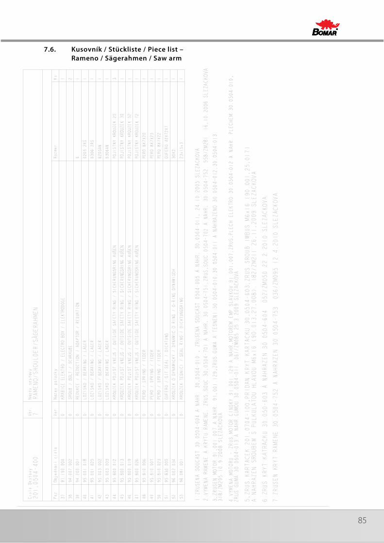
85
7.6. Kusovník / Stückliste / Piece list – Rameno / Sägerahmen / Saw arm

86 Manual version: 1.04 / Mar. 2010Manual rev.: 1
7.7. Konzola / Konzole / Console
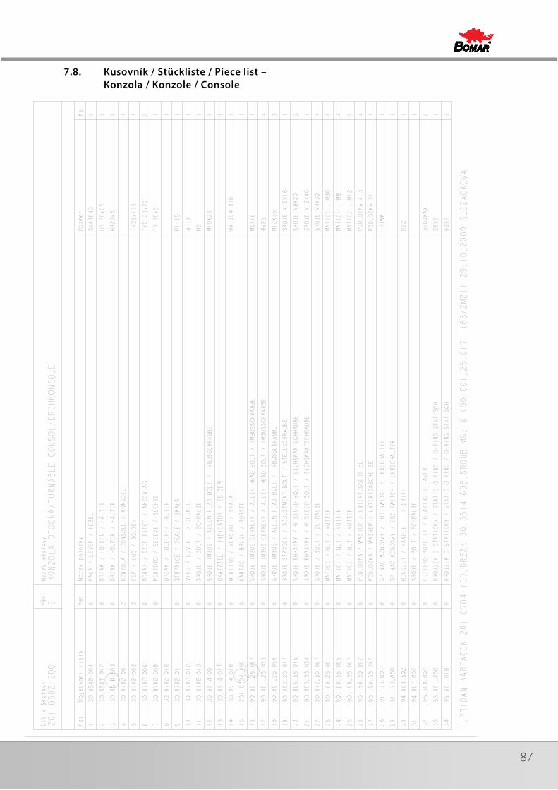
87
7.8. Kusovník / Stückliste / Piece list – Konzola / Konzole / Console

88 Manual version: 1.04 / Mar. 2010Manual rev.: 1
7.9. Svěrák / Schraubstock / Vice
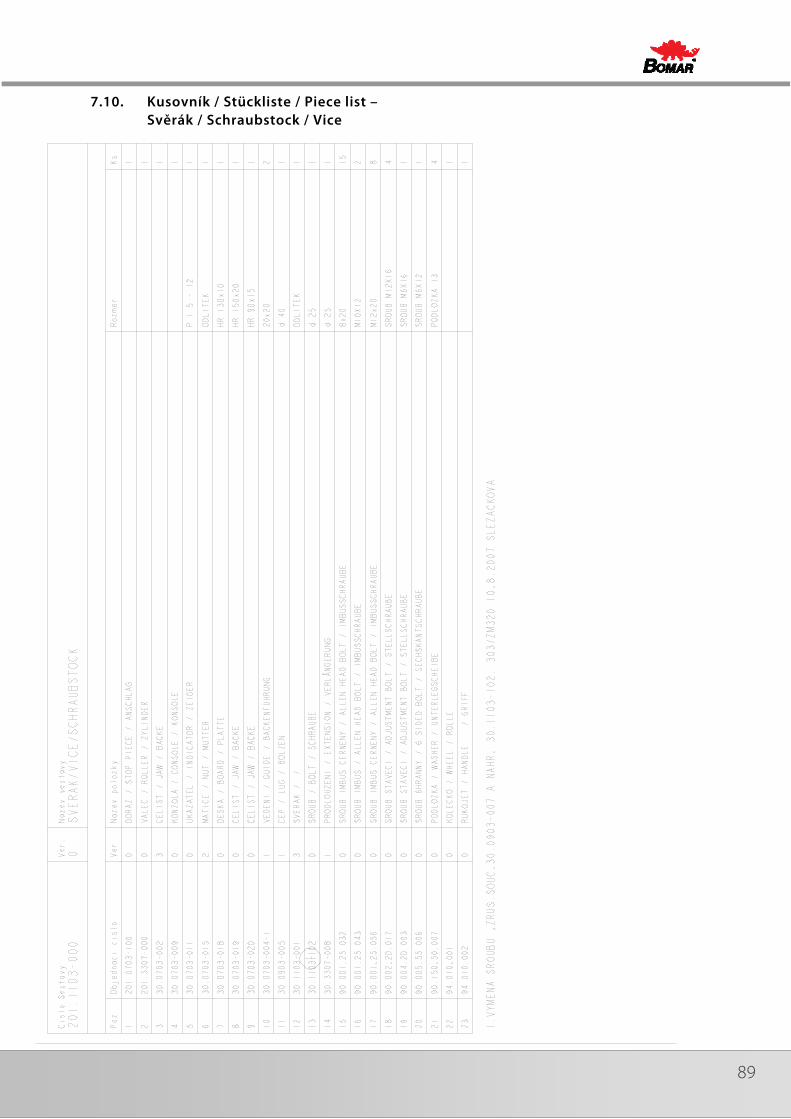
89
7.10. Kusovník / Stückliste / Piece list – Svěrák / Schraubstock / Vice
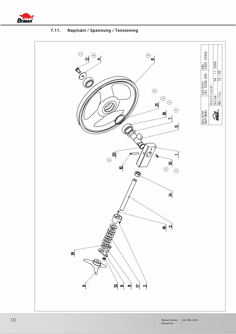
90 Manual version: 1.04 / Mar. 2010Manual rev.: 1
7.11. Napínání / Spannung / Tensioning
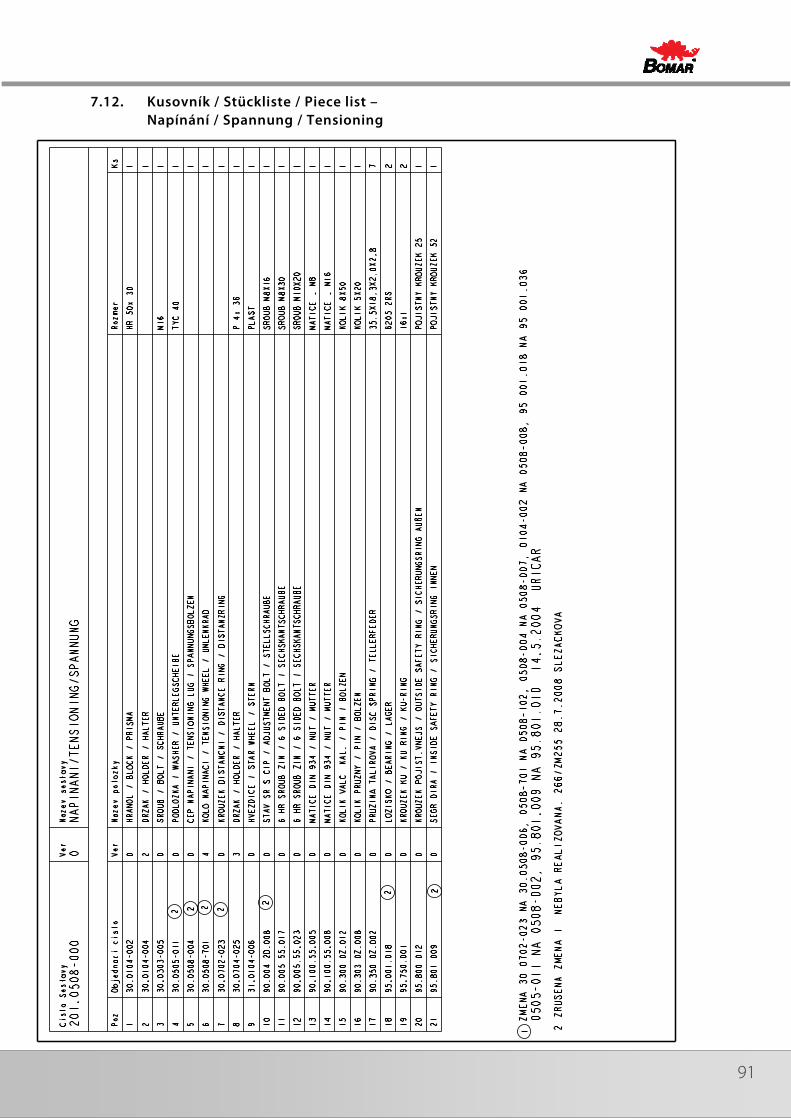
91
7.12. Kusovník / Stückliste / Piece list – Napínání / Spannung / Tensioning
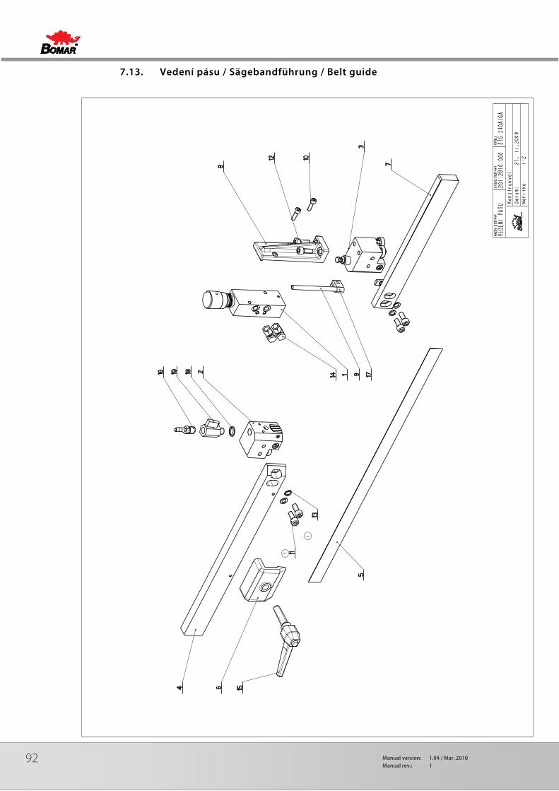
92 Manual version: 1.04 / Mar. 2010Manual rev.: 1
7.13. Vedení pásu / Sägebandführung / Belt guide
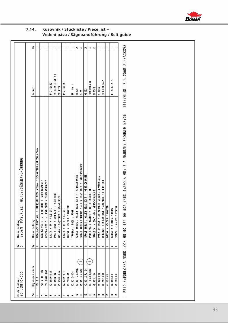
93
7.14. Kusovník / Stückliste / Piece list – Vedení pásu / Sägebandführung / Belt guide

94 Manual version: 1.04 / Mar. 2010Manual rev.: 1
7.15. Vodící kostka / Führungsklotz / Guiding cube
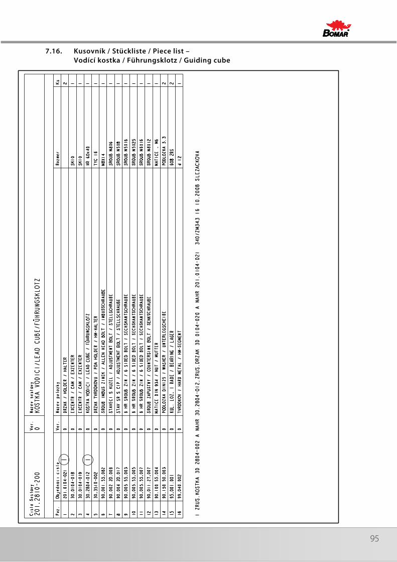
95
7.16. Kusovník / Stückliste / Piece list – Vodící kostka / Führungsklotz / Guiding cube

96 Manual version: 1.04 / Mar. 2010Manual rev.: 1
7.17. Vodící kostka / Führungsklotz / Guiding cube
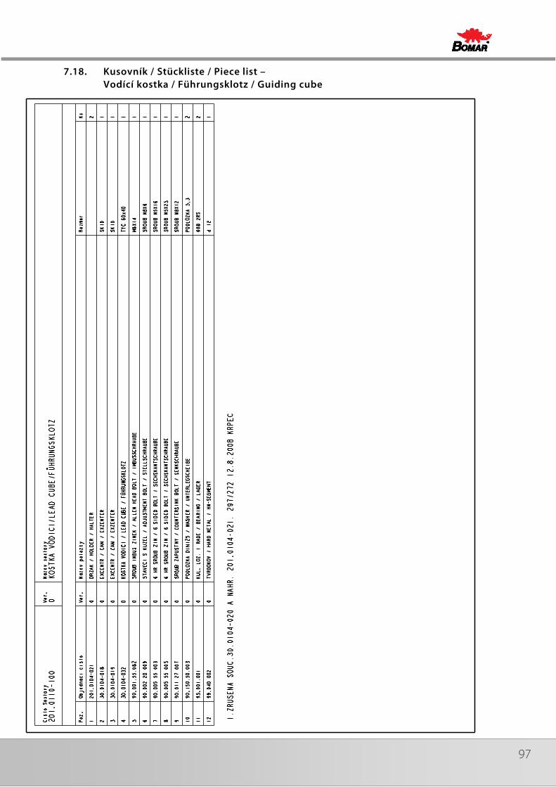
97
7.18. Kusovník / Stückliste / Piece list – Vodící kostka / Führungsklotz / Guiding cube
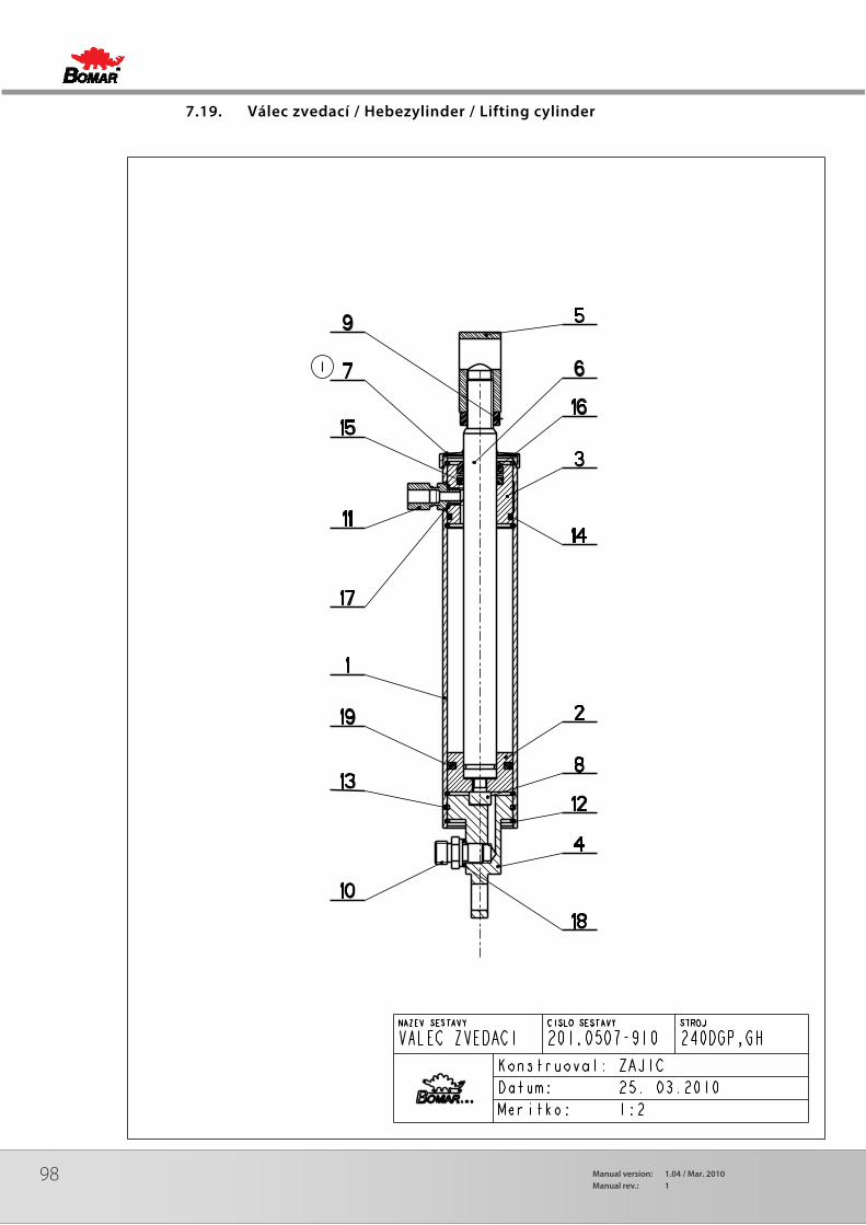
98 Manual version: 1.04 / Mar. 2010Manual rev.: 1
7.19. Válec zvedací / Hebezylinder / Lifting cylinder
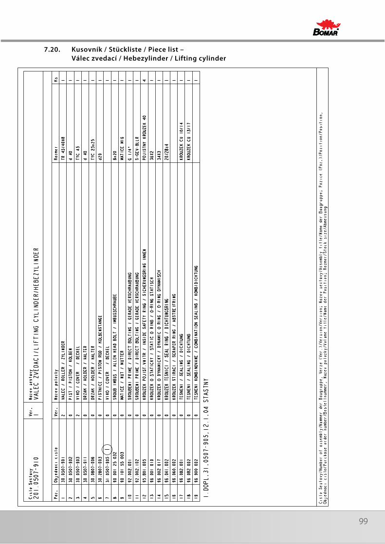
99
7.20. Kusovník / Stückliste / Piece list – Válec zvedací / Hebezylinder / Lifting cylinder
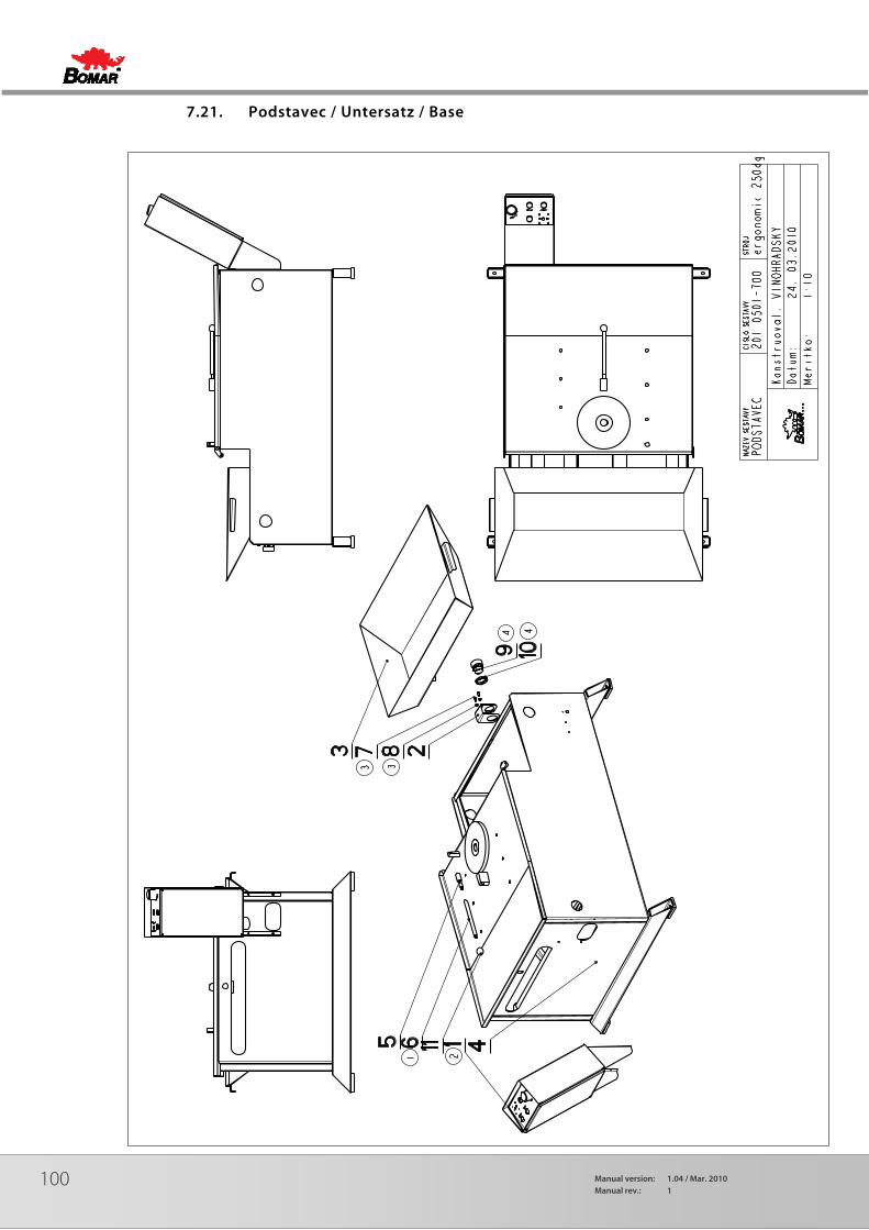
100 Manual version: 1.04 / Mar. 2010Manual rev.: 1
7.21. Podstavec / Untersatz / Base
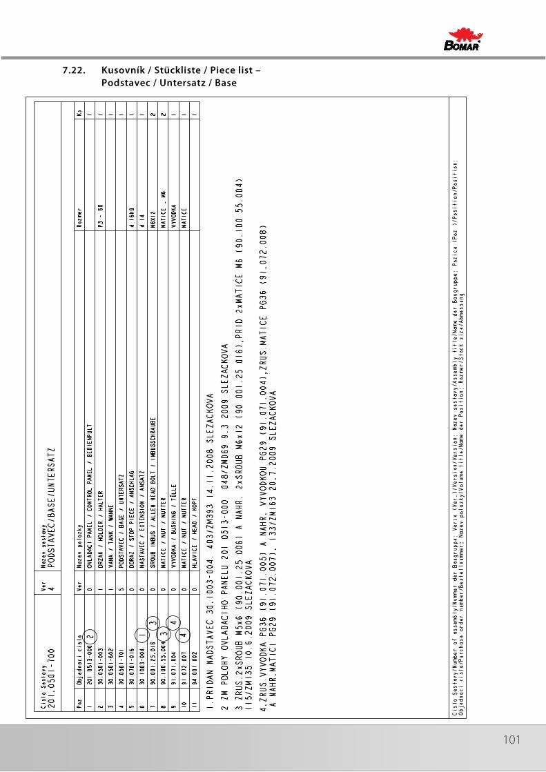
101
7.22. Kusovník / Stückliste / Piece list – Podstavec / Untersatz / Base
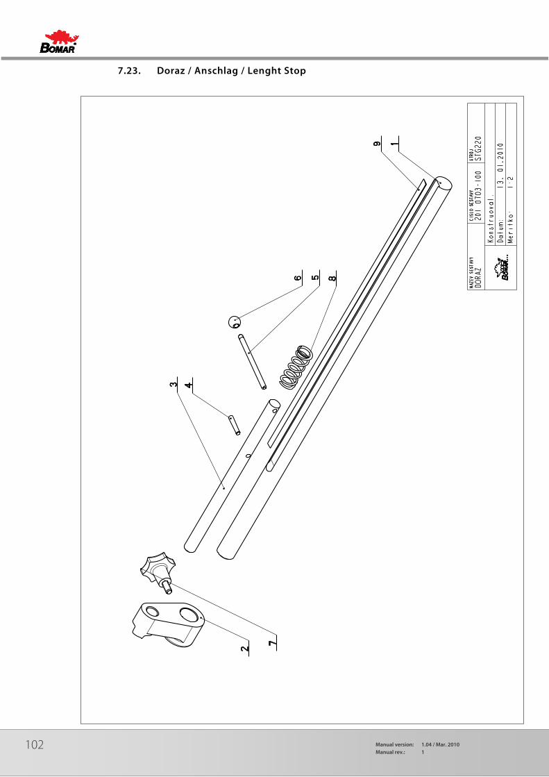
102 Manual version: 1.04 / Mar. 2010Manual rev.: 1
7.23. Doraz / Anschlag / Lenght Stop

103
7.24. Kusovník / Stückliste / Piece list – Doraz / Anschlag / Lenght Stop
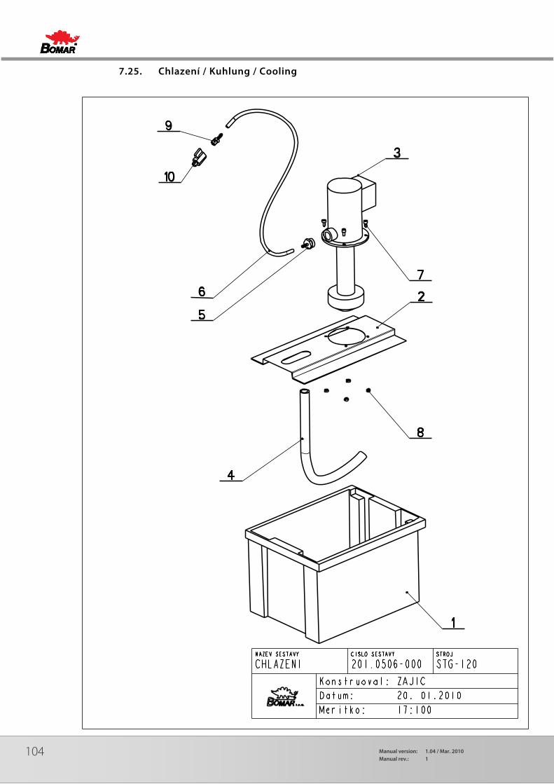
104 Manual version: 1.04 / Mar. 2010Manual rev.: 1
7.25. Chlazení / Kuhlung / Cooling
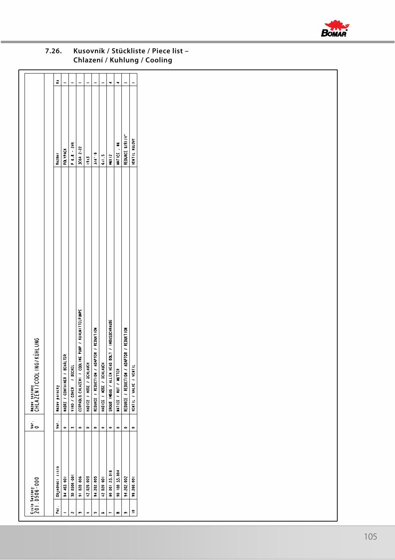
105
7.26. Kusovník / Stückliste / Piece list – Chlazení / Kuhlung / Cooling

106 Manual version: 1.04 / Mar. 2010Manual rev.: 1
7.27. Válec / Zylinder / Roller

107
7.28. Kartáč / Bürste / Brush
Related Documents