E N G L I S H I T A L I A N O u s e a n d m a i n t e n a n c e m a n u a l ERCOLE AUTOMATION FOR SLIDING GATES (230/110/400V) V05/2019

Welcome message from author
This document is posted to help you gain knowledge. Please leave a comment to let me know what you think about it! Share it to your friends and learn new things together.
Transcript
ENGLISH
ITALIANO
use and maintenance manual
ERCOLEAUTOMATION FOR SLIDING GATES (230/110/400V)
V05/2019
WARNINGS FOR THE INSTALLER
1) ATTENTION! To ensure the safety of people, it is 13) Make sure that a differential switch with threshold ofimportant that you read all the following 0.03 A is fitted upstream of the system.instructions. Incorrect installation or incorrect use
14) Make sure that the earthing system is perfectlyof the product could cause serious harm to people.constructed, and connect metal parts of the means of
2) Carefully read the instructions before beginning to the closure to it.install the product.
15) The safety devices (EN 12978 standard) protect3) Do not leave packing materials (plastic, polystyrene, any danger areas against mechanical movementetc.) within reach of children as such materials are Risks, such as crushing, dragging, and shearing.potential sources of danger.
16) Use of at least one indicator-light is recommended4) Store these instructions for future reference. for every system, as well as a warning sign adequately
secured to the frame structure, in addition to the safety5) This product was designed and built strictly for the devices.use indicated in this documentation. Any other use, notexpressly indicated here, could compromise the good 17) QUIKO declines all liability as concernscondition/operation of the product and/or be a source of safety and efficient operation of the automated system,danger. if system components not produced by QUIKO
are used.6) QUIKO declines all liability caused byimproper use or use other than that for which the 18) For maintenance, strictly use original parts byautomated system was intended. QUIKO
7) Do not install the equipment in an explosive 19) Do not in any way modify the components of theatmosphere: the presence of inflammable gas or fumes automated system.is a serious danger to safety.
20) The installer shall supply all information concerning8) The mechanical parts must conform to the manual operation of the system in case of anprovisions of Standards EN 12604 and EN 12605. emergency, and shall hand over to the user theFor non-EU countries, to obtain an adequate level of warnings handbook supplied with the product.safety, the Standards mentioned above must be
21) Do not allow children or adults to stay near theobserved, in addition to national legal regulations.product while it is operating.
9) QUIKO is not responsible for failure to22) Keep radiocontrols or other pulse generators awayobserve Good Technique in the construction of thefrom children, to prevent the automated system fromclosing elements to be motorised, or for anybeing activated involuntarily.deformation that may occur during use.
23) The user must not attempt any kind of repair or10) The installation must conform to Standards ENdirect action whatever and contact qualified personnel12453 and EN 12445. For non-EU countries, to obtainonly.an adequate level of safety, the Standards mentioned
above must be observed, in addition to national legal24) Transit is permitted only when the automatedregulations.system is idle.
11) Before attempting any job on the system, cut out25) Maintenance: check at least every 6 months theelectrical power.efficiency of the system, particularly the efficiency ofthe safety devices (including, where foreseen, the12) The mains power supply of the automated systemoperator thrust force) and of the release devices.must be fitted with an all-pole switch with contact
opening distance of 3mm or greater. Use of a 6A26) Anything not expressly specified in thesethermal breaker with all-pole circuit break isinstructions is not permitted.recommended.
GENERAL SAFETY OBLIGATIONS
These instructions apply to the following models: ERCOLEThe automatisms ERCOLE gearmotor is anelectro-mechanical operator designed for moving slidinggates.The non-reversing reduction system ensures the gate ismechanically locked when the gearmotor is not operating,therefore it is not necessary to install any electric lockA convenient manual release with customised key makes itpossible to move the gate in the event of a power failure ormalfunction of the operator.The ERCOLE gearmotor was designed and builtfor controlling vehicle access.AVOID ANY OTHER USE WHATEVER.
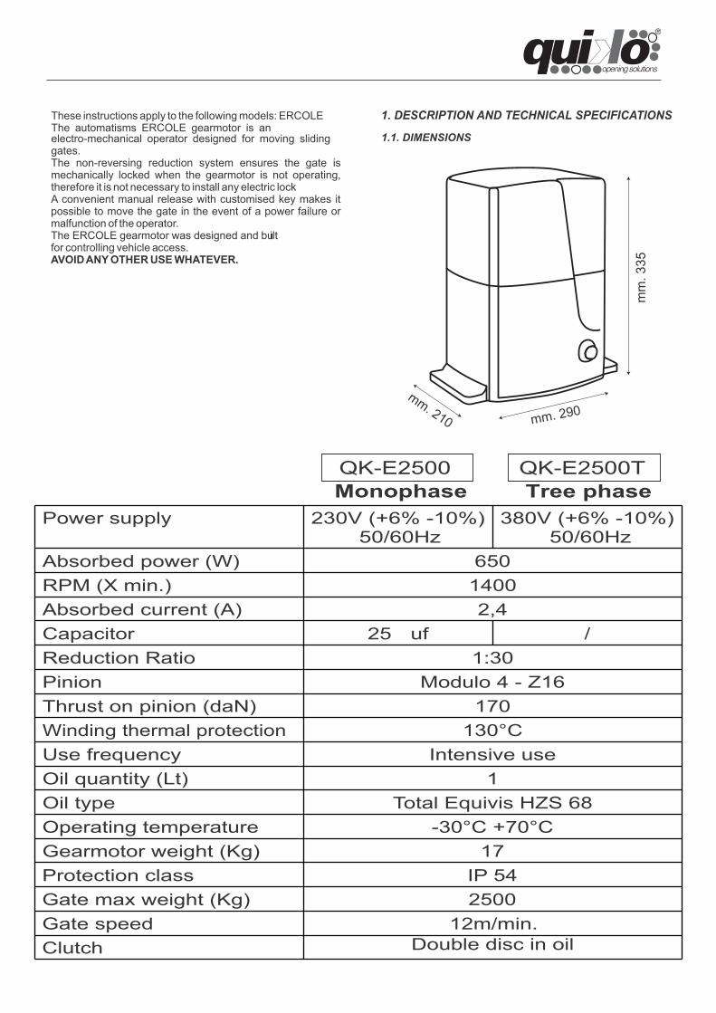
1. DESCRIPTION AND TECHNICAL SPECIFICATIONS
1.1. DIMENSIONS
QK-E2500
Power supply 230V (+6% -10%)50/60Hz
380V (+6% -10%)50/60Hz
Absorbed power (W) 650RPM (X min.) 1400Absorbed current (A) 2,4Capacitor 25 uf /Reduction Ratio 1:30Pinion Modulo 4 - Z16Thrust on pinion (daN) 170Winding thermal protection 130°CUse frequency Intensive useOil quantity (Lt) 1Oil type Total Equivis HZS 68Operating temperature -30°C +70°CGearmotor weight (Kg) 17Protection class IP 54Gate max weight (Kg) 2500Gate speed 12m/min.Clutch Double disc in oil
Monophase Tree phaseQK-E2500T
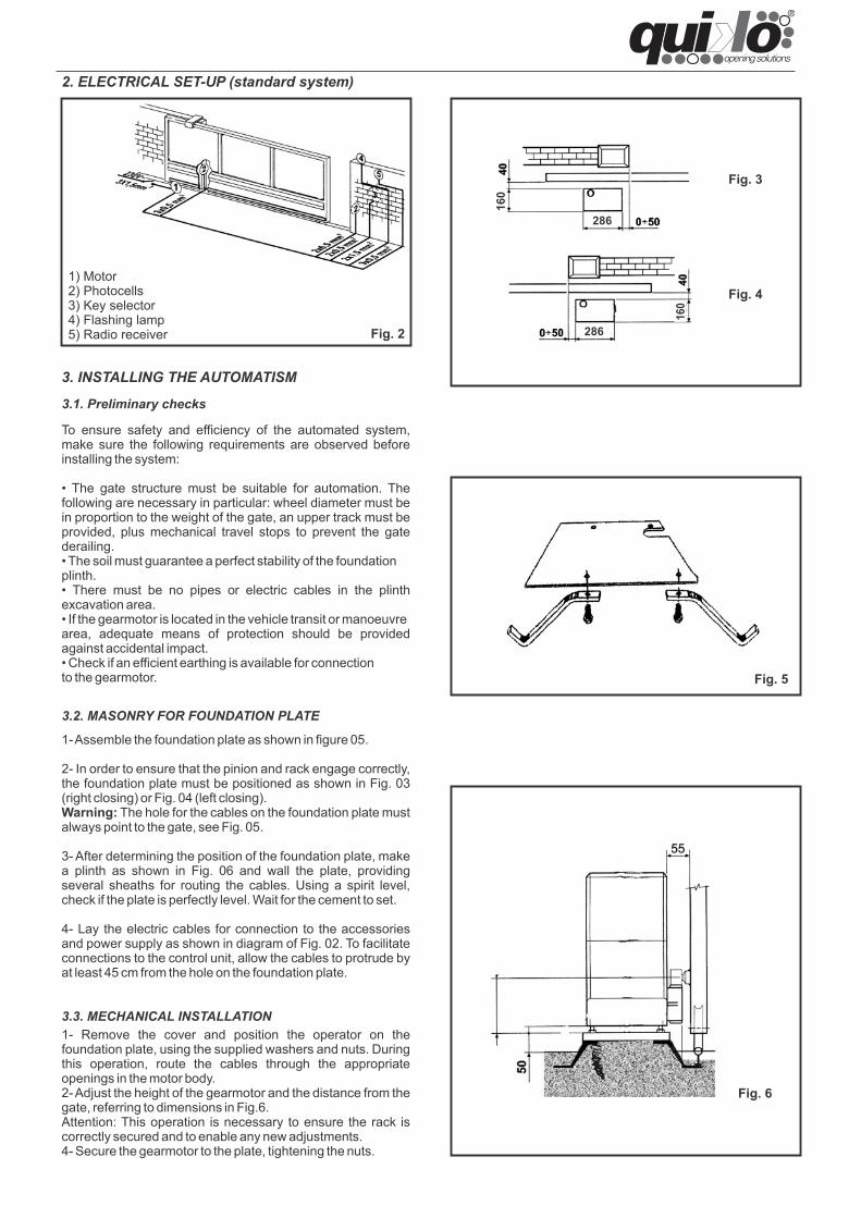
2. ELECTRICAL SET-UP (standard system)
3.1. Preliminary checks
3.3. MECHANICAL INSTALLATION
3. INSTALLING THE AUTOMATISM
3.2. MASONRY FOR FOUNDATION PLATE
1- Assemble the foundation plate as shown in figure 05.
2- In order to ensure that the pinion and rack engage correctly,the foundation plate must be positioned as shown in Fig. 03(right closing) or Fig. 04 (left closing).Warning: The hole for the cables on the foundation plate mustalways point to the gate, see Fig. 05.
3- After determining the position of the foundation plate, makea plinth as shown in Fig. 06 and wall the plate, providingseveral sheaths for routing the cables. Using a spirit level,check if the plate is perfectly level. Wait for the cement to set.
4- Lay the electric cables for connection to the accessoriesand power supply as shown in diagram of Fig. 02. To facilitateconnections to the control unit, allow the cables to protrude byat least 45 cm from the hole on the foundation plate.
1- Remove the cover and position the operator on thefoundation plate, using the supplied washers and nuts. Duringthis operation, route the cables through the appropriateopenings in the motor body.2- Adjust the height of the gearmotor and the distance from thegate, referring to dimensions in Fig.6.Attention: This operation is necessary to ensure the rack iscorrectly secured and to enable any new adjustments.4- Secure the gearmotor to the plate, tightening the nuts.
1) Motor 2) Photocells3) Key selector4) Flashing lamp5) Radio receiver Fig. 2
Fig. 3
Fig. 4
Fig. 5
To ensure safety and efficiency of the automated system,make sure the following requirements are observed beforeinstalling the system:
• The gate structure must be suitable for automation. Thefollowing are necessary in particular: wheel diameter must bein proportion to the weight of the gate, an upper track must beprovided, plus mechanical travel stops to prevent the gatederailing.• The soil must guarantee a perfect stability of the foundationplinth.• There must be no pipes or electric cables in the plinthexcavation area.• If the gearmotor is located in the vehicle transit or manoeuvrearea, adequate means of protection should be providedagainst accidental impact.• Check if an efficient earthing is available for connectionto the gearmotor.
286
286
160
160
Fig. 6
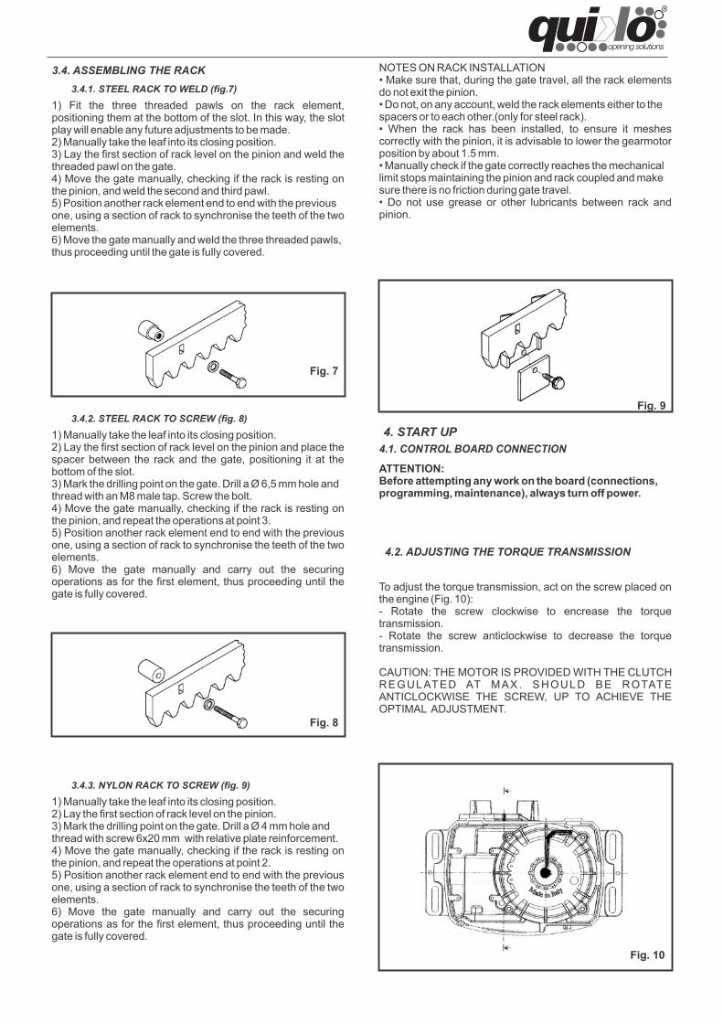
1) Fit the three threaded pawls on the rack element,positioning them at the bottom of the slot. In this way, the slotplay will enable any future adjustments to be made.2) Manually take the leaf into its closing position.3) Lay the first section of rack level on the pinion and weld thethreaded pawl on the gate.4) Move the gate manually, checking if the rack is resting onthe pinion, and weld the second and third pawl.5) Position another rack element end to end with the previousone, using a section of rack to synchronise the teeth of the twoelements.6) Move the gate manually and weld the three threaded pawls,thus proceeding until the gate is fully covered.
1) Manually take the leaf into its closing position.2) Lay the first section of rack level on the pinion and place thespacer between the rack and the gate, positioning it at thebottom of the slot.3) Mark the drilling point on the gate. Drill a Ø 6,5 mm hole andthread with an M8 male tap. Screw the bolt.4) Move the gate manually, checking if the rack is resting onthe pinion, and repeat the operations at point 3.5) Position another rack element end to end with the previousone, using a section of rack to synchronise the teeth of the twoelements.6) Move the gate manually and carry out the securingoperations as for the first element, thus proceeding until thegate is fully covered.
1) Manually take the leaf into its closing position.2) Lay the first section of rack level on the pinion.3) Mark the drilling point on the gate. Drill a Ø 4 mm hole andthread with screw 6x20 mm with relative plate reinforcement.4) Move the gate manually, checking if the rack is resting onthe pinion, and repeat the operations at point 2.5) Position another rack element end to end with the previousone, using a section of rack to synchronise the teeth of the twoelements.6) Move the gate manually and carry out the securingoperations as for the first element, thus proceeding until thegate is fully covered.
ATTENTION:Before attempting any work on the board (connections,programming, maintenance), always turn off power.
3.4. ASSEMBLING THE RACK3.4.1. STEEL RACK TO WELD (fig.7)
3.4.2. STEEL RACK TO SCREW (fig. 8)
3.4.3. NYLON RACK TO SCREW (fig. 9)
4. START UP4.1. CONTROL BOARD CONNECTION
Fig. 7
Fig. 8
Fig. 9
NOTES ON RACK INSTALLATION• Make sure that, during the gate travel, all the rack elementsdo not exit the pinion.• Do not, on any account, weld the rack elements either to thespacers or to each other.(only for steel rack).• When the rack has been installed, to ensure it meshescorrectly with the pinion, it is advisable to lower the gearmotorposition by about 1.5 mm.• Manually check if the gate correctly reaches the mechanicallimit stops maintaining the pinion and rack coupled and makesure there is no friction during gate travel.• Do not use grease or other lubricants between rack andpinion.
To adjust the torque transmission, act on the screw placed onthe engine (Fig. 10):- Rotate the screw clockwise to encrease the torquetransmission.- Rotate the screw anticlockwise to decrease the torquetransmission.
CAUTION: THE MOTOR IS PROVIDED WITH THE CLUTCHREGULATED AT MAX. SHOULD BE ROTATEANTICLOCKWISE THE SCREW, UP TO ACHIEVE THEOPTIMAL ADJUSTMENT.
4.2. ADJUSTING THE TORQUE TRANSMISSION
Fig. 10
Once installation of the operator has been completed, make a careful functional check of all accessories and safety devicesconnected.Give the Client the “User Guide” and demonstrate the correct operation and use of the gearmotor, highlighting the potentiallydangerous zones of the automated system.
4.3. AUTOMATISM SYSTEM TEST
6. RESTORING NORMAL OPERATIONTo prevent an inadvertent boost could move the gate during the maneuver, turn off the power supply , before locking again the motor.LEVER UNLOCK1) Close the unlock lever.2) Move the gate until the release system meshes.3) Close the plastic fold and restore the power supply to the system
7. MAINTENANCECheck the functional operation of the system at least every six months, especially the efficiency of the safety devices (including theoperator thrust force) and the release devices.
7.1. OIL FILLING
Periodically check the amount of oil within the operator.For medium-low frequency of use, an annual check is enough, for more intensive use it is recommended every 6 months.To make filling, unscrew the cap and load until the level.
8. REPAIRS
For any repairs, contact QUIKO’s authorised Repair Centres.
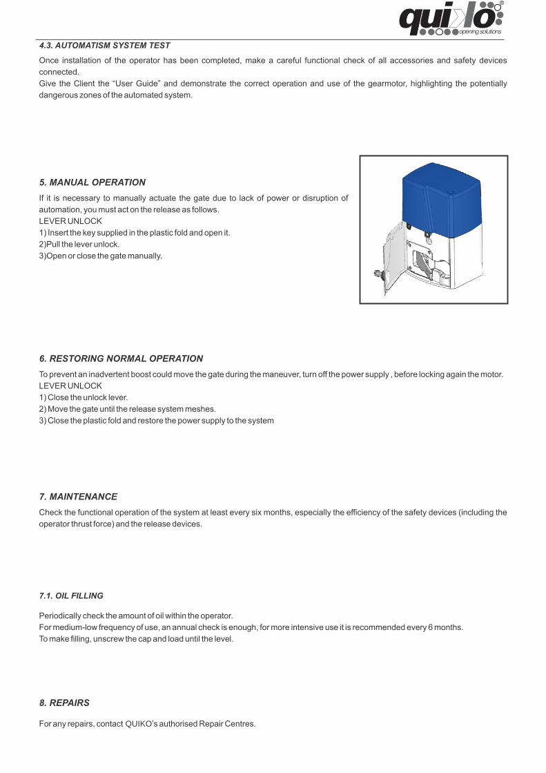
5. MANUAL OPERATIONIf it is necessary to manually actuate the gate due to lack of power or disruption ofautomation, you must act on the release as follows.LEVER UNLOCK1) Insert the key supplied in the plastic fold and open it.2)Pull the lever unlock.3)Open or close the gate manually.
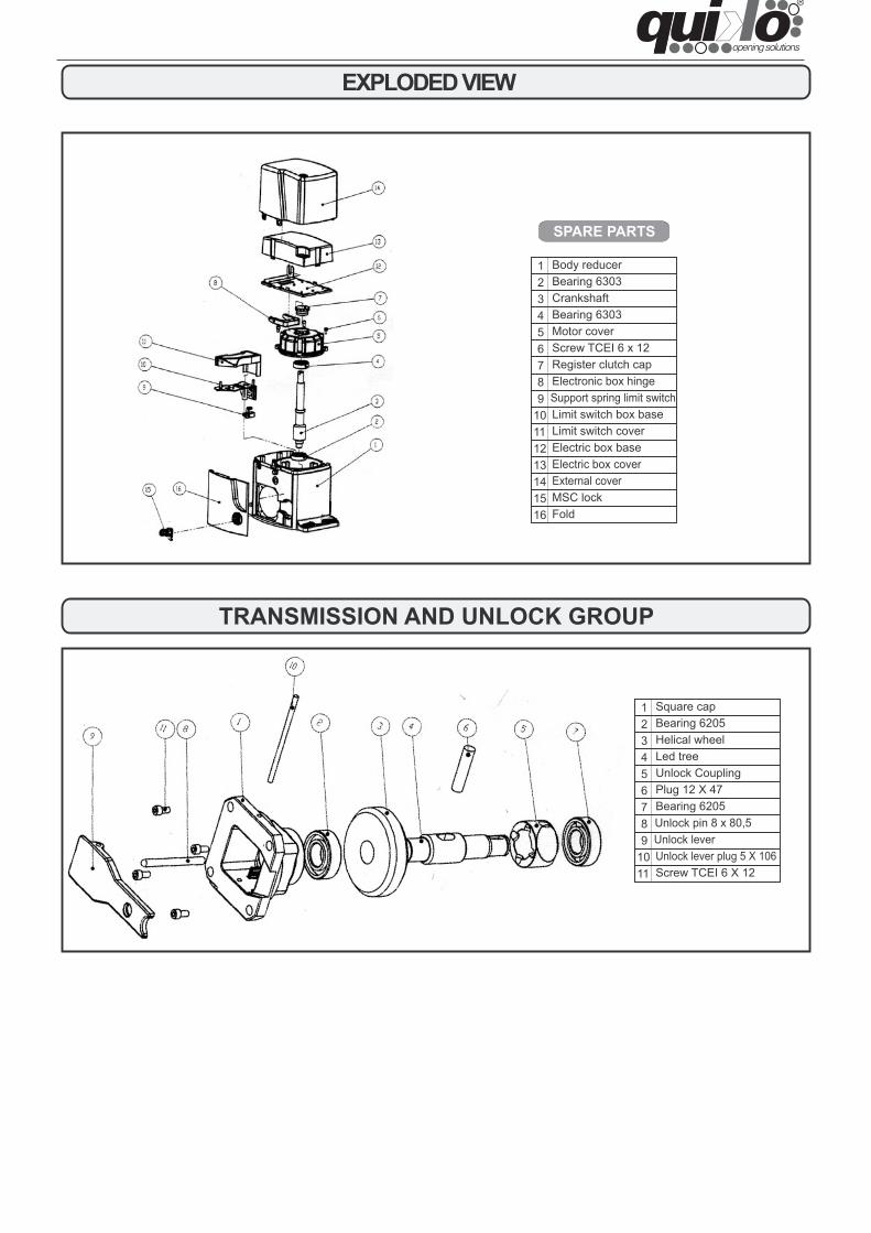
EXPLODED VIEW
SPARE PARTS
1 Body reducer2 Bearing 63033 Crankshaft4 Bearing 63035 Motor cover6 Screw TCEI 6 x 127 Register clutch cap8 Electronic box hinge9 Support spring limit switch
10 Limit switch box base11 Limit switch cover12 Electric box base
External coverMSC lockFold
Electric box cover13141516
1 Square cap2 Bearing 62053 Helical wheel4 Led tree5 Unlock Coupling6 Plug 12 X 477 Bearing 62058 Unlock pin 8 x 80,59 Unlock lever
10 Unlock lever plug 5 X 10611 Screw TCEI 6 X 12
TRANSMISSION AND UNLOCK GROUP
If installed and used correctly, the ERCOLEautomated system will ensure a high degree of safety.Some simple rules regarding behaviour will avoid any accidentaltrouble:• Do not stand near the automated system and do not allowchildren and other people or things to stand there, especiallywhile it is operating.• Keep radiocontrols or any other pulse generator well away fromchildren to prevent the automated system from being activatedinvoluntarily.• Do not allow children to play with the automated system.• Do not willingly obstruct gate movement.• Prevent any branches or shrubs from interfering with gatemovement.• Keep light signalling systems efficient and clearly visible.• Do not attempt to activate the gate by hand unless you havereleased it.• In the event of malfunctions, release the gate to allow accessand wait for qualified technical personnel to do the necessarywork.• After enabling manual operation, switch off the power supplyto the system before restoring normal operation.• Do not make any alterations to the components of theautomated system.• Do not attempt any kind of repair of direct action whatsoeverand contact qualified personnel only.• Call in qualified personnel at least every 6 months to check theefficiency of the automated system, safety devices and earthconnection.
Read the instructions carefully before using the productand keep them for future consultation.
GENERAL SAFETY RULES
DESCRIPTION
is an electro-mechanical operator transmitting motion to thesliding gate with a rack pinion appropriately coupled to thegate.
Operation of the sliding gate is controlled by an electroniccontrol unit housed inside the operator or in a hermeticallysealed outdoor enclosure.When, with the gate closed, the unit receives an openingcommand by radiocontrol or from another suitable device, itactivates the motor until the opening position is reached.If automatic operation was set, the gate re-closesautomatically after the selected pause time has elapsed.If the semi-automatic operation was set, a second pulse mustbe sent to close the gate again.An opening pulse during re-closing, always causes movementto be reversed.A stop pulse (if provided) always stops movement.The light signalling indicates that the gate is currently moving.For details on sliding gate behaviour in different functionlogics, consult the installation technician.The automated systems include obstacle-detection and/orsafety devices (photocells, edges) that prevent the gate fromclosing when there is an obstacle in the area they protect.The system ensures mechanical locking when the motor is notoperating and, therefore, it is not necessary to install any lock.Manual opening is, therefore, only possible by using therelease system.
The gearmotor ERCOLE have a mechanical clutch, so itdoesn’t need any electronic clutch.A convenient manual release with customised key makes itpossible to move the gate in the event of a power failure ormalfunction.
MANUAL OPERATIONIf it is necessary to manually actuate the gate due to lack ofpower or disruption of automation, you must act on the releaseas follows.LEVER UNLOCK1) Insert the key supplied in the plastic fold and open it.2)Pull the lever unlock.3)Open or close the gate manually.
RESTORING NORMAL OPERATIONTo prevent an inadvertent boost could move the gate duringthe maneuver, turn off the power supply , before locking againthe motor.LEVER UNLOCK1) Close the unlock lever.2) Move the gate until the release system meshes.3) Close the plastic fold and restore the power supply to thesystem
The ERCOLE automated system is ideal for controllingvehicle access areas of medium transit frequency.The ERCOLE automated system for sliding gates

ENGLISH
DECLARATION OF CONFORMITY (OF THE MANUFACTURER)
Manufacturer: QUIKO ITALY
hereby declares, under his liability, that the products: QK-E2500, QK-2500T
are in compliance with the essential safety requirements of the regulations:
Electromagnetic Compatibility Directive .........................2004/108/EC Low Voltage Directive ..................................................... .2014/35/EC Machinery Directive .........................................................2006/42/EC
and their amendments and modifications, and with the regulations set forth by the National Legislative Body of the country in which the machinery is destined for use.
Via Seccalegno, 19 36040 Sossano (VI) Italia
Managing Director
Luca Borinato
Sossano, 1/1/2019

DECLARATION OF CONFORMITY (OF THE INSTALLER)
The undersigned: Address: in charge of the set-up, declares that the product: Gate type: Location: are in compliance with the essential safety requirements of the regulations: Electro magnetic Compatibility Directive .........................2004/108/EC
Low Voltage Directive ............................................................2014/35/EC
Machinery Directive ................................................................2006/42/EC
and also declares that the related and/or specific national technical regulations have been followed:
EN 12453/EN 12445 on Industrial, Commercial and Residential Gates and Doors – Safe Use of Motorized Doors – Requirements and Classification – Test Methods;
EN 12604/ EN 12605 on Industrial, Commercial and Residential Gates and Doors – Mechanical Aspects – Requirements and Classification – Test Methods;
CEI 64/8 Electrical Systems Using Nominal Tension Not Higher Than 1000V a.c. and 1500 V d.c.;
EN 13241-1 (Industrial, commercial and garage doors and gates), conformity evaluation (6.3).
Notes: Place and date: ………………………………………


QUIKO ITALYVia Seccalegno, 1936040 Sossano (VI) - ItalyTel. +39 0444 785513Fax +39 0444 [email protected]

Manual de uso y mantenim
iento
V05/2019
ERCOLE AUTOMATIZACIÓN DE CANCELAS CORREDERAS
E S P A Ñ O L
ADVERTENCIAS PARA EL INSTALADOR
REGLAS GENERALES PARA LA SEGURIDAD1) ¡ATENCION! Para poder garantizar la seguridad 13) Comprobar que antes de la instalación eléctricapersonal, es importante seguir atentamente todas haya un interruptor diferencial con umbral de 0,03 Alas instrucciones. La instalación incorrecta o eluso inapropiado del producto pueden provocar 14) Cerciorarse de que la conexión a tierra estágraves daños personales. correctamente realizada. Conectar a ella las partes
metálicas del cierre y el cable amarillo/verde del2) Leer detenidamente las instrucciones antes de equipo automático.empezar a instalar el equipo.
15) Los dispositivos de seguridad (por ej.: fotocélulas,3) No dejar los materiales de embalaje al alcance de bandas sensibles, etc.) permiten evitar peligroslos niños, ya que constituyen fuentes potenciales de derivados de acciones mecánicas de movimientopeligro. (aplastamiento, arrastre, cercenamiento).
4) Conservar las instrucciones para futuras consultas. 16) Para cada equipo es indispensable utilizar por lomenos una señalización luminosa así como también
5) Este producto ha sido proyectado y construido un letrero de señalización correctamente fijado a laexclusivamente para el uso indicado en el presente estructura de la cancela, además de los dispositivosmanual. Cualquier aplicación no expresamente de seguridad.indicada podría resultar perjudicial para el equipo opara las personas circunstantes. 17) El fabricante declina toda responsabilidad
respecto a la seguridad y al correcto funcionamiento6) El fabricante declina toda responsabilidad ante del equipo automático en el caso de que se utiliceninconvenientes derivados del uso impropio del equipo otros componentes del sistema que no hayan sidoo de aplicaciones distintas de aquella para la cual el producidos por dicha empresa.mismo fue creado.
18) Para el mantenimiento, utilizar exclusivamente7) No instalar el aparato en una atmósfera explosiva. recambios originales.La presencia de gases o humos inflamables implicaun grave peligro para la seguridad. 19) No efectuar ninguna modificación de los
elementos que componen el sistema de8) Los elementos mecánicos de construcción deben automatización.ser conformes a lo establecido en las Normativas UNI8612, EN pr EN 12604 y CEN pr EN 12605. 20) El técnico instalador debe facilitar toda laEn los países no pertenecientes a la CEE, además de información relativa al funcionamiento manual delrespetarse las normativas nacionales, para obtener sistema en casos de emergencia, y entregar alun nivel de seguridad adecuado deben cumplirse las usuario del sistema las "Instrucciones para el usuario"normas arriba mencionadas. que se anexa al producto.
9) El fabricante no es responsable por la 21) No permitir que los niños, ni ninguna otra persona,inobservancia de los adecuados criterios técnicos en permanezcan en proximidad del equipo durante ella construcción de los cierres que se van a motorizar, funcionamiento.ni por las deformaciones que puedan verificarse conel uso. 22) No dejar al alcance de los niños mandos a
distancia ni otros generadores de impulsos, para10) La instalación debe efectuarse de conformidad evitar que el equipo automático sea accionadocon las Normas UNI 8612, CEN pr EN 12453 y CEN pr involuntariamente.EN 12635. El nivel de seguridad del equipoautomático debe ser C+E. 23) El usuario debe abstenerse de todo intento de
reparación o de intervención directa; es preciso11) Antes de efectuar cualquier operación en el consultar siempre con personal especializado.equipo, desconéctelo de la alimentación eléctrica.
24) Todo aquello que no esté expresamente12) La red de alimentación del equipo automático especificado en estas instrucciones habrá dedebe estar dotada de un interruptor omnipolar con considerarse no permitido.una distancia de apertura de los contactos igual osuperior a 3 mm. Como alternativa, se aconsejautilizar un interruptor magnetotérmico de 6 A coninterrupción omnipolar.

1.1. MEDIDAS
1.3. CARACTERÍSTICAS TÉCNICAS DE LOS MOTORREDUCTORES
E SPAÑOL
AUTOMATISMOS ERCOLE
Las presentes instrucciones son válidas para los siguientesmodelos: ERCOLE
Los automatismos ERCOLE para cancelas correderasson actuadores electromecánicos que transmitenel movimiento ala hoja mediante un piñón con cremallera,acoplado ala cancela.El sistema garantiza el bloqueo mecánico cuando el motor noestá en marcha, lo que permite prescindir de cerraduras. Losmotorreductores están dotados de embragues mecánicos oelectrónicosregulables, que funcionan como medio deseguridad antia plasta miento y proveen a la detención y albloqueo de la cancela. Un cómodo mecanismo de desbloqueomanual permite moverla cancela en caso de corte de energíao fallo del sistemaLos automatismos ERCOLE han sido proyectados yconstruidos para controlar el acceso vehicular.Evítese todo otro uso.
1. DESCRIPCIÓN Y CARACTERISTICAS TÉCNICAS
Alimentación 230V (+6% -10%)50/60Hz
380V (+6% -10%)50/60Hz
Potencia absorbida (W) 650Velocidad de rotación (rev/min.) 1400Corriente absorbita (A) 2,4Condensador de arranque 25 uf /Relación de reducción 1:30Pinón Modulo 4 - Z16Empuje màx (daN) 170Protecciòn tèrmica bobinado 130°CFrequencia de uso Uso intensivoCantidad de aceite (Lt) 1Aceite Total Equivis HZS 68T emperatura de funcionamiento -30°C +70°CPeso motorreductor (Kg) 17Grado de protecciòn IP 54Peso max cacela (Kg) 2500Velocidad de la cancela 12 m/min.Embrague Doble disco en aceite
MODELOQK-E2500
MonofásicoQK-E2500T
Trifásico
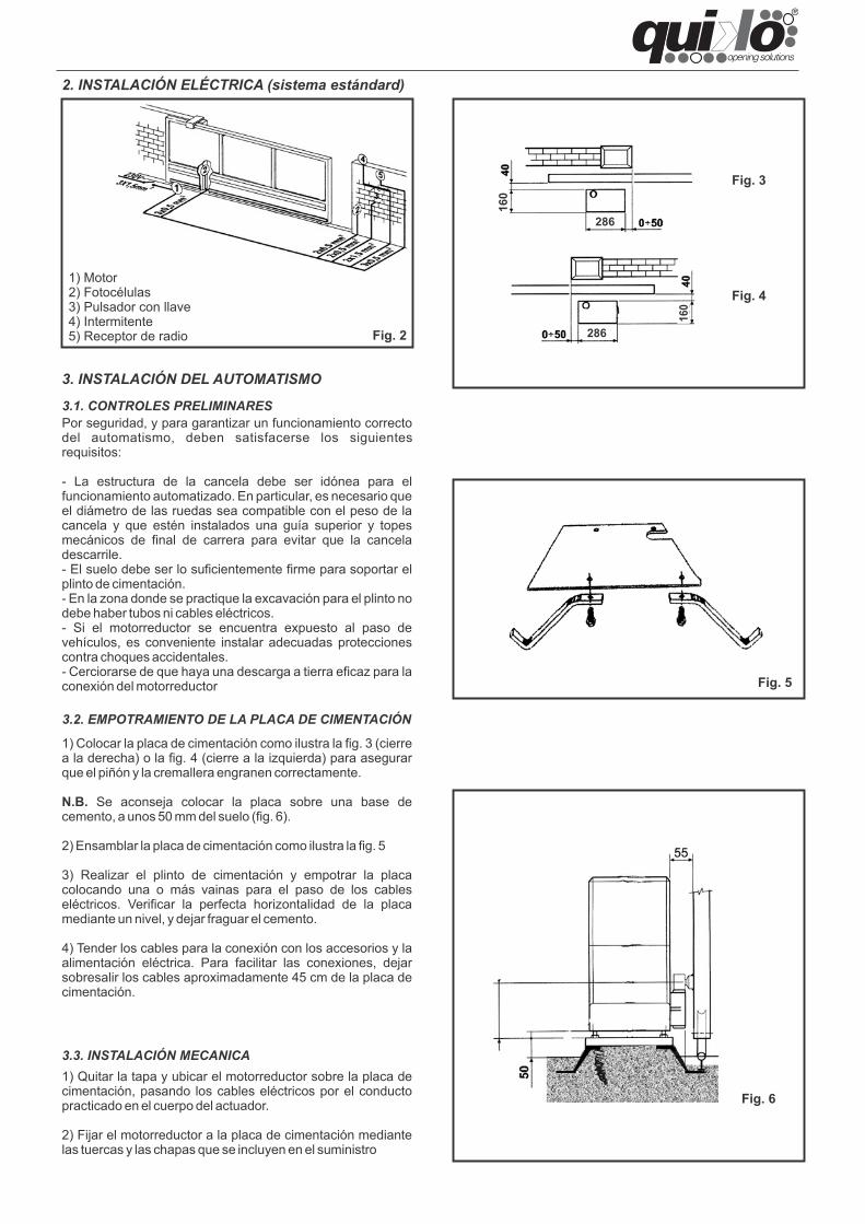
Fig. 2
Fig. 3
Fig. 4
Fig. 5
286
286
160
160
Fig. 6
3. INSTALACIÓN DEL AUTOMATISMO
3.1. CONTROLES PRELIMINARESPor seguridad, y para garantizar un funcionamiento correctodel automatismo, deben satisfacerse los siguientesrequisitos:
- La estructura de la cancela debe ser idónea para elfuncionamiento automatizado. En particular, es necesario queel diámetro de las ruedas sea compatible con el peso de lacancela y que estén instalados una guía superior y topesmecánicos de final de carrera para evitar que la canceladescarrile.- El suelo debe ser lo suficientemente firme para soportar elplinto de cimentación.- En la zona donde se practique la excavación para el plinto nodebe haber tubos ni cables eléctricos.- Si el motorreductor se encuentra expuesto al paso devehículos, es conveniente instalar adecuadas proteccionescontra choques accidentales.- Cerciorarse de que haya una descarga a tierra eficaz para laconexión del motorreductor
1) Motor2) Fotocélulas3) Pulsador con llave4) Intermitente5) Receptor de radio
2. INSTALACIÓN ELÉCTRICA (sistema estándard)
3.2. EMPOTRAMIENTO DE LA PLACA DE CIMENTACIÓN
1) Colocar la placa de cimentación como ilustra la fig. 3 (cierrea la derecha) o la fig. 4 (cierre a la izquierda) para asegurarque el piñón y la cremallera engranen correctamente.
N.B. Se aconseja colocar la placa sobre una base decemento, a unos 50 mm del suelo (fig. 6).
2) Ensamblar la placa de cimentación como ilustra la fig. 5
3) Realizar el plinto de cimentación y empotrar la placacolocando una o más vainas para el paso de los cableseléctricos. Verificar la perfecta horizontalidad de la placamediante un nivel, y dejar fraguar el cemento.
4) Tender los cables para la conexión con los accesorios y laalimentación eléctrica. Para facilitar las conexiones, dejarsobresalir los cables aproximadamente 45 cm de la placa decimentación.
3.3. INSTALACIÓN MECANICA1) Quitar la tapa y ubicar el motorreductor sobre la placa decimentación, pasando los cables eléctricos por el conductopracticado en el cuerpo del actuador.
2) Fijar el motorreductor a la placa de cimentación mediantelas tuercas y las chapas que se incluyen en el suministro
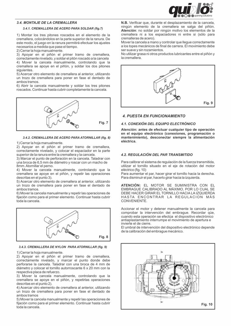
1) Cerrar la hoja manualmente.2) Apoyar en el piñón el primer tramo de cremallera,correctamente nivelado, y marcar el punto donde debeperforarse la cancela. Taladrar con una broca de 4 mm dediámetro y colocar el tornillo autorroscante 6 x 20 mm con larespectiva placa de refuerzo.3) Mover la cancela manualmente, controlando que lacremallera se apoye en el piñón, y repetirlas operacionesdescritas en el punto 2).4) Acercar otro elemento de cremallera al anterior, utilizandoun trozo de cremallera para poner en fase el dentado deambos tramos5) Mover la cancela manualmente y repetir las operaciones defijación como para el primer elemento. Continuar hasta cubrirtoda la cancela.
Atención: antes de efectuar cualquier tipo de operaciónen el equipo electrónico (conexiones, programación omantenimiento), desconectar siempre la alimentacióneléctrica.
Fig. 7
Fig. 8
Fig. 9
N.B. Verificar que, durante el desplazamiento de la cancela,ningún elemento de la cremallera se salga del piñón.Atención: no soldar por ningún motivo los elementos de lacremallera ni a los espaciadores ni entre si (sólo paracremalleras de acero).Mover la cancela a mano y controlar que llegue correctamentea los topes mecánicos de final de carrera. El movimiento debeser suave y sin rozamientos.No utilizar grasa ni otros productos lubricantes entre el piñón yla cremallera.
Fig. 10
3.4. MONTAJE DE LA CREMALLERA3.4.1. CREMALLERA DE ACERO PARA SOLDAR (fig.7)
1) Montar los tres pitones roscados en el elemento de lacremallera, colocándolos en la parte superior de la ranura. Deeste modo, el juego en la ranura permitirá efectuar los ajustesnecesarios a medida que pase el tiempo.2) Cerrar la hoja manualmente.3) Apoyar en el piñón el primer tramo de cremallera,correctamente nivelado, y soldar el pitón roscado a la cancela4) Mover la cancela manualmente, controlando que lacremallera se apoye en el piñón, y soldar los dos pitonessiguientes.5) Acercar otro elemento de cremallera al anterior, utilizandoun trozo de cremallera para poner en fase el dentado deambos tramos.6) Abrir la cancela manualmente y soldar los tres pitonesroscados. Continuar hasta cubrir completamente la cancela.
3.4.2. CREMALLERA DE ACERO PARA ATORNILLAR (fig. 8)
1) Cerrar la hoja manualmente.2) Apoyar en el piñón el primer tramo de cremallera,correctamente nivelado, y colocar el espaciador en la partesuperior de la ranura entre la cremallera y la cancela.3) Marcar el punto de perforación en la cancela. Taladrar conuna broca de 6,5 mm de diámetro y roscar con un macho de8mm.Atornillar el perno.4) Mover la cancela manualmente, controlando que lacremallera se apoye en el piñón, y repetir las operacionesdescritas en el punto 3).5) Acercar otro elemento de cremallera al anterior, utilizandoun trozo de cremallera para poner en fase el dentado deambos tramos.6) Mover la cancela manualmente y repetir las operaciones defijación como para el primer elemento. Continuar hasta cubrirtoda la cancela.
3.4.3. CREMALLERA DE NYLON PARA ATORNILLAR (fig. 9)
4. PUESTA EN FUNCIONAMIENTO
4.1. CONEXIÓN DEL EQUIPO ELECTRÓNICO
4.2. REGULACIÓN DEL PAR TRANSMITIDO
Para calibrar el sistema de regulación de la fuerza transmitida,utilizar el tornillo situado en el eje de rotación del motoreléctrico (fig. 10)Para aumentar el par, hacer girar el tornillo hacia la derecha.Para disminuir el par, hacerlo girar hacia la izquierda.
ATENCIÓN: EL MOTOR SE SUMINISTRA CON ELEMBRAGUE CALIBRADO AL MÁXIMO, POR LO CUAL SEDEBE HACER GIRAR EL TORNILLO HACIA LA IZQUIERDAH A S TA E N CO N TR A R L A R E G U LA C I ON M Á SCONVENIENTE.
Accionar el motor y detener manualmente la cancela paracomprobar la intervención del embrague. Recordar qúe,cuando esta operación se efectúa el dispositivo electrónicoantiaplastamiento interrumpe el movimiento de apertura einvierte el de cierre.El umbral de intervención del dispositivo electrónico dependede la calibración del embrague mecánico.
Una vez concluida la instalación,comprobar minuciosamente el funcionamiento del automatismo y de todos los accesoriosconectados a él. Entregar al cliente un ejemplar de la «Guja para el usuario» e ilustrarle las condiciones correctas de funcionamientoy el empleo del motorreductor, remarcando las zonas de peligro potencial del automatismo
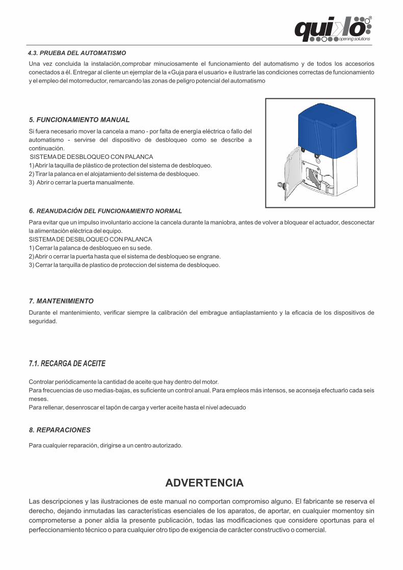
5. FUNCIONAMIENTO MANUALSi fuera necesario mover la cancela a mano - por falta de energía eléctrica o fallo delautomatismo - servirse del dispositivo de desbloqueo como se describe acontinuación.SISTEMA DE DESBLOQUEO CON PALANCA1) Abrir la taquilla de plàstico de protection del sistema de desbloqueo.2) Tirar la palanca en el alojatamiento del sistema de desbloqueo.3) Abrir o cerrar la puerta manualmente.
6. REANUDACIÓN DEL FUNCIONAMIENTO NORMAL
Para evitar que un impulso involuntario accione la cancela durante la maniobra, antes de volver a bloquear el actuador, desconectarla alimentaciòn elèctrica del equipo.SISTEMA DE DESBLOQUEO CON PALANCA1) Cerrar la palanca de desbloqueo en su sede.2) Abrir o cerrar la puerta hasta que el sistema de desbloqueo se engrane.3) Cerrar la tarquilla de plastico de proteccion del sistema de desbloqueo.
7. MANTENIMIENTODurante el mantenimiento, verificar siempre la calibración del embrague antiaplastamiento y la eficacia de los dispositivos deseguridad.
7.1. RECARGA DE ACEITE
Controlar periódicamente la cantidad de aceite que hay dentro del motor.Para frecuencias de uso medias-bajas, es suficiente un control anual. Para empleos más intensos, se aconseja efectuarlo cada seismeses.Para rellenar, desenroscar el tapón de carga y verter aceite hasta el nivel adecuado
8. REPARACIONES
Para cualquier reparación, dirigirse a un centro autorizado.
Las descripciones y las ilustraciones de este manual no comportan compromiso alguno. El fabricante se reserva elderecho, dejando inmutadas las características esenciales de los aparatos, de aportar, en cualquier momentoy sincomprometerse a poner aldia la presente publicación, todas las modificaciones que considere oportunas para elperfeccionamiento técnico o para cualquier otro tipo de exigencia de carácter constructivo o comercial.
ADVERTENCIA
4.3. PRUEBA DEL AUTOMATISMO
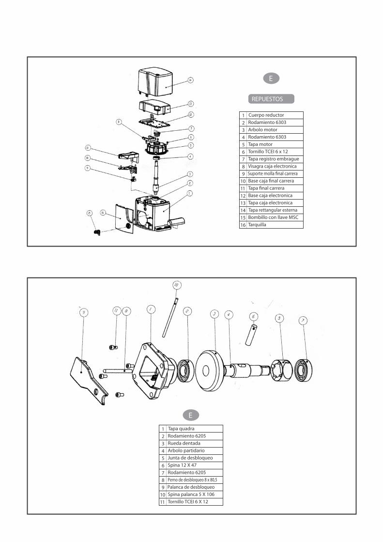
REPUESTOS
E
1 Cuerpo reductor
2 Rodamiento 6303
3 Arbolo motor
4 Rodamiento 6303
5 Tapa motor
6 Tornillo TCEI 6 x 12
7 Tapa registro embrague
8 Visagra caja electronica
9 Suporte molla �nal carrera
10 Base caja �nal carrera
11 Tapa �nal carrera
12 Base caja electronica
13 Tapa caja electronica
14 Tapa rettangular esterna
15 Bombillo con llave MSC
16 Tarquilla
E
1 Tapa quadra
2 Rodamiento 6205
3 Rueda dentada
4 Arbolo partidario
5 Junta de desbloqueo
6 Spina 12 X 47
7 Rodamiento 6205
8 Perno de desbloqueo 8 x 80,5
9 Palanca de desbloqueo
10 Spina palanca 5 X 10⁶
11 Tornillo TCEI 6 X 12
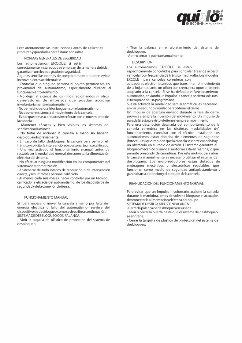
Los automatismos ERCOLE si estáncorrectamente instalados y se emplean de la manera debida,garantizan un elevado grado de seguridad.Algunas sencillas normas de comportamiento pueden evitarinconvenientes accidentales:- Controlar que ninguna persona ni objeto permanezca enproximidad del automatismo, especialmente durante elfuncionamiento del mismo.- No dejar al alcance de los niños radiomandos ni otrosgeneradores de impulsos que puedan accionarinvoluntariamente el automatismo.- No permitir que los niños jueguen con el automatismo.- No oponer resistencia al movimiento de la cancela.- Evitar que ramas o arbustos inter�eran con el movimiento dela cancela.- Mantener e�caces y bien visibles los sistemas deseñalización luminosa.- No tratar de accionar la cancela a mano sin haberladesbloqueado previamente.- En caso de fallo, desbloquear la cancela para permitir eltránsito y solicitarla intervención de personal técnico cali�cado.- Una vez activado el funcionamiento manual, antes derestablecer la modalidad normal, desconectar la alimentacióneléctrica del sistema.- No efectuar ninguna modi�cación en los componentes delsistema de automatización.- Abstenerse de todo intento de reparación o de intervencióndirecta, y recurrir sólo a personal cali�cado.- AI menos cada seis meses, hacer controlar por un técnicocali�cado la e�cacia del automatismo, de los dispositivos deseguridad y de la conexión de tierra.
NORMAS GENERALES DE SEGURIDADDESCRIPTIÓN
Los automatismos ERCOLE se estánespeci�camente concebidos para controlar áreas de accesovehicular con frecuencia de tránsito media-alta. Los modelosERCOLE para cancelas correderas sonactuadores electromecánicos que transmiten el movimientode la hoja mediante un piñón con cremallera oportunamenteacoplado a la cancela. Si se ha de�nido el funcionamientoautomático, enviando un impulso la cancela se cierra sola trasel tiempo de pausa programado.Si está activada la modalidad semiautomática, es necesarioenviar un segundo impulso para obtener el cierre.Un impulso de apertura enviado durante la fase de cierreprovoca siempre la inversión del movimiento. Un impulso deparada (si está previsto) detiene siempre el movimiento.Para una descripción detallada del comportamiento de lacancela corredera en las distintas modalidades de'funcionamiento, consultar con el técnico instalador. Losautomatismos están dotados de elementos de seguridad(fotocélulas) que impiden que la cancela se cierre cuando hayun obstáculo en su radio de acción. El sistema garantiza elbloqueo mecánico cuando el motor no está en marcha, lo quepermite prescindir de cerraduras. Por este motivo, para abrirla cancela manualmente es necesario utilizar el sistema dedesbloqueo. Los motorreductores están dotados deembragues mecánicos o electrónicos regulables, quefuncionan como medio de seguridad antiaplastamiento ygarantizan la detención y el bloqueo de la cancela.
FUNCIONAMIENTO MANUAL
Si fuera necesario mover la cancela a mano por falta deenergía eléctrica o fallo del automatismo- servirse deldispositivo de desbloqueo como se describe a continuación.SISTEMA DE DESBLOQUEO CON PALANCA.- Abrir la taquilla de plàstico de protection del sistema dedesbloqueo.
- Tirar la palanca en el alojatamiento del sistema dedesbloqueo.- Abrir o cerrar la puerta manualmente.
REANUDACIÓN DEL FUNCIONAMIENTO NORMAL
Para evitar que un impulso involuntario accione la canceladurante la maniobra, antes de volver a bloquear el actuador,desconectar la alimentación eléctrica del equipo.SISTEMA DE DESBLOQUEO CON PALANCA- Cerrar la palanca de desbloqueo en su sede.- Abrir o cerrar la puerta hasta que el sistema de desbloqueose engrane.- Cerrar la tarquilla de plastico de proteccion del sistema dedesbloqueo.
Leer atentamente las instrucciones antes de utilizar elproducto y guardarlas para futuras consultas
DECLARATION OF CONFORMITY (OF THE MANUFACTURER)
Manufacturer: QUIKO ITALY
hereby declares, under his liability, that the products: QK-E2500, QK-2500T
are in compliance with the essential safety requirements of the regulations:
Electromagnetic Compatibility Directive .........................2004/108/EC Low Voltage Directive ..................................................... .2014/35/EC Machinery Directive .........................................................2006/42/EC
and their amendments and modifications, and with the regulations set forth by the National Legislative Body of the country in which the machinery is destined for use.
Via Seccalegno, 19 36040 Sossano (VI) Italia
Managing Director
Luca Borinato
Sossano, 1/1/2019
DECLARATION OF CONFORMITY (OF THE INSTALLER)
The undersigned: Address: in charge of the set-up, declares that the product: Gate type: Location: are in compliance with the essential safety requirements of the regulations: Electro magnetic Compatibility Directive .........................2004/108/EC
Low Voltage Directive ............................................................2014/35/EC
Machinery Directive ................................................................2006/42/EC
and also declares that the related and/or specific national technical regulations have been followed:
EN 12453/EN 12445 on Industrial, Commercial and Residential Gates and Doors – Safe Use of Motorized Doors – Requirements and Classification – Test Methods;
EN 12604/ EN 12605 on Industrial, Commercial and Residential Gates and Doors – Mechanical Aspects – Requirements and Classification – Test Methods;
CEI 64/8 Electrical Systems Using Nominal Tension Not Higher Than 1000V a.c. and 1500 V d.c.;
EN 13241-1 (Industrial, commercial and garage doors and gates), conformity evaluation (6.3).
Notes: Place and date: ………………………………………

QUIKO ITALYVia Seccalegno, 1936040 Sossano (VI) - ItalyTel. +39 0444 785513Fax +39 0444 [email protected]
Related Documents