ENR202 Mechanics of Materials Lecture 7B Slides and Notes Slide 1 Do not remove this notice. COMMMONWEALTH OF AUSTRALIA Copyright Regulations 1969 WARNING This material has been produced and communicated to you by or on behalf of the University of South Australia pursuant to Part VB of the Copyright Act 1968 (the Act). The material in this communication may be subject to copyright under the Act. Any further reproduction or communication of this material by you may be the subject of copyright protection under the Act. Do not remove this notice. Copyright Notice Slide 2 Lecture 7b – Deflections of Beams ENR 202 Mechanics of Materials Welcome to lecture Summary 7b. In this lecture, we will continue with our work on deflections of beams, by practising with some problems. The following slides give five different problems. If you can, try to work out the problems yourself and then check your work against the solution (at least for the last couple of problems). Remember to click on the live links for further information. Slide 3 Determine the equation of the deflection curve for a simple beam AB supporting a uniform load of intensity q (see Figure). Also determine the maximum deflection at the middle of the beam and the angles of rotation a and b at the supports. Exercise 1 ENR202 7b -- Slide No. 3 Try this one first by yourself if you can. If you have problems, look through the solution on the following two slides. This exercise is based on a simple example: a simply supported beam subjected to a uniformly distributed load ‘q’ acting vertically downwards throughout the length of the beam L, as shown in the figure. You need to calculate the maximum deflection delta at the centre of the beam and the angles of rotation at point A and point B, as shown in the figure.

Welcome message from author
This document is posted to help you gain knowledge. Please leave a comment to let me know what you think about it! Share it to your friends and learn new things together.
Transcript
ENR202 Mechanics of Materials Lecture 7B Slides and Notes
Slide 1
Do not remove this notice.
COMMMONWEALTH OF AUSTRALIACopyright Regulations 1969
WARNING
This material has been produced and communicated to you by or on
behalf of the University of South Australia pursuant to Part VB of the
Copyright Act 1968 (the Act).
The material in this communication may be subject to copyright under the
Act. Any further reproduction or communication of this material by you
may be the subject of copyright protection under the Act.
Do not remove this notice.
Copyright Notice
Slide 2
Lecture 7b – Deflections of Beams
ENR 202 Mechanics of Materials
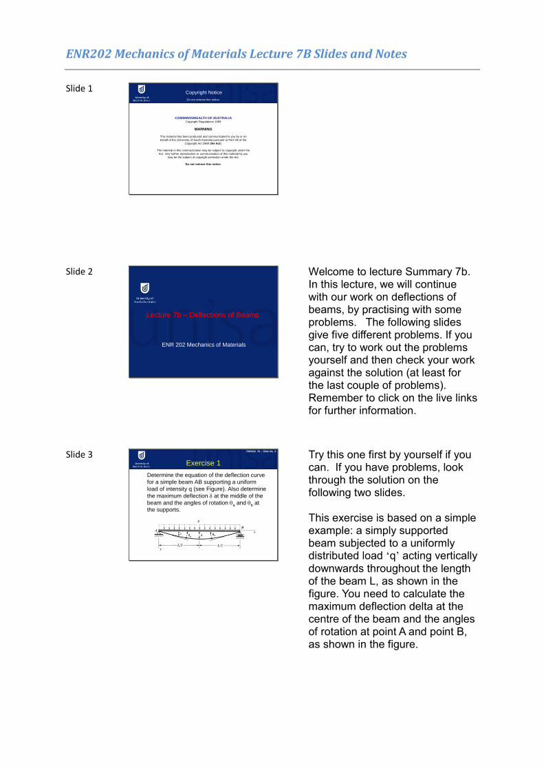
Welcome to lecture Summary 7b. In this lecture, we will continue with our work on deflections of beams, by practising with some problems. The following slides give five different problems. If you can, try to work out the problems yourself and then check your work against the solution (at least for the last couple of problems). Remember to click on the live links for further information.
Slide 3
Determine the equation of the deflection curve
for a simple beam AB supporting a uniform
load of intensity q (see Figure). Also determine
the maximum deflection at the middle of the
beam and the angles of rotation a and b at
the supports.
Exercise 1
ENR202 7b -- Slide No. 3
Try this one first by yourself if you can. If you have problems, look through the solution on the following two slides. This exercise is based on a simple example: a simply supported beam subjected to a uniformly distributed load ‘q’ acting vertically downwards throughout the length of the beam L, as shown in the figure. You need to calculate the maximum deflection delta at the centre of the beam and the angles of rotation at point A and point B, as shown in the figure.
ENR202 Mechanics of Materials Lecture 7B Slides and Notes
Slide 4
ENR202 7b -- Slide No. 4
Exercise 1 Solution (1)
Figure 1
Figure 2
(1)
(2)
(3)
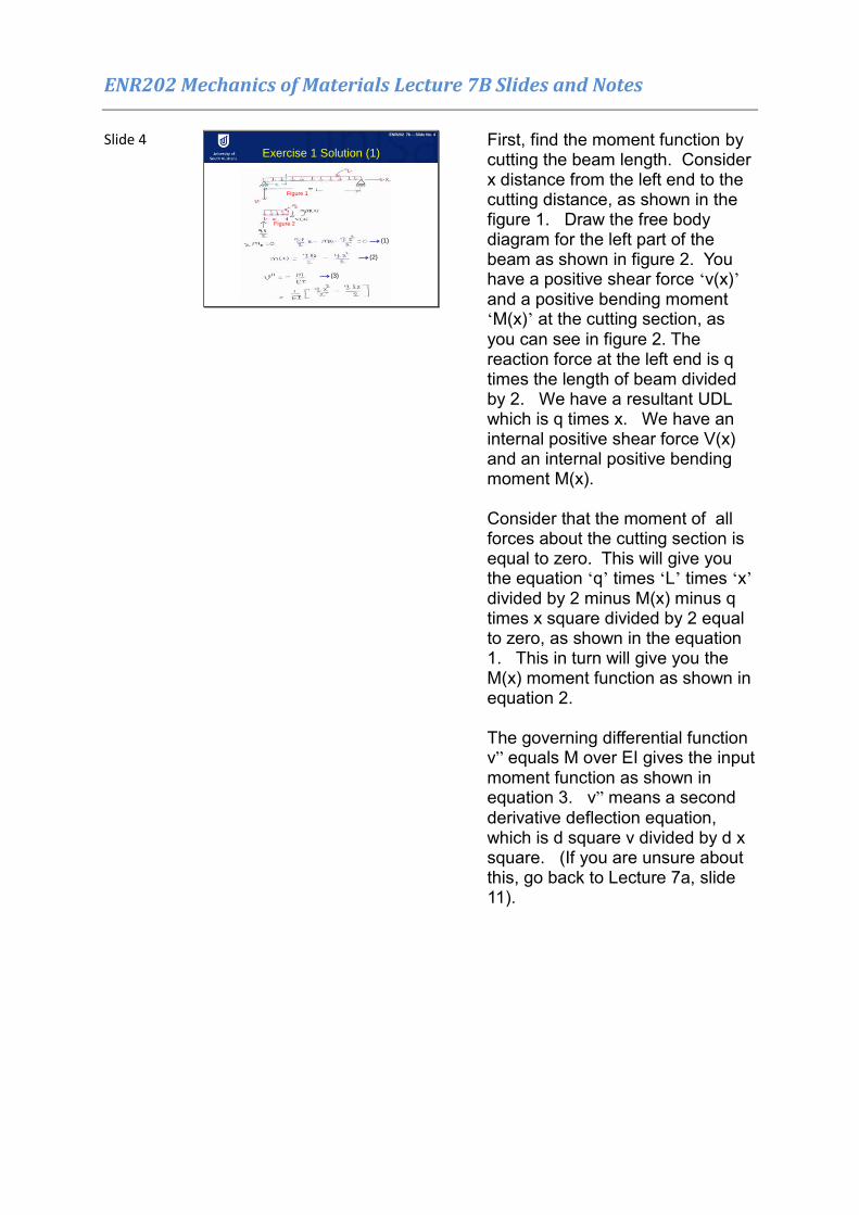
First, find the moment function by cutting the beam length. Consider x distance from the left end to the cutting distance, as shown in the figure 1. Draw the free body diagram for the left part of the beam as shown in figure 2. You have a positive shear force ‘v(x)’ and a positive bending moment ‘M(x)’ at the cutting section, as you can see in figure 2. The reaction force at the left end is q times the length of beam divided by 2. We have a resultant UDL which is q times x. We have an internal positive shear force V(x) and an internal positive bending moment M(x). Consider that the moment of all forces about the cutting section is equal to zero. This will give you the equation ‘q’ times ‘L’ times ‘x’ divided by 2 minus M(x) minus q times x square divided by 2 equal to zero, as shown in the equation 1. This in turn will give you the M(x) moment function as shown in equation 2. The governing differential function v” equals M over EI gives the input moment function as shown in equation 3. v” means a second
derivative deflection equation, which is d square v divided by d x square. (If you are unsure about this, go back to Lecture 7a, slide 11).

ENR202 Mechanics of Materials Lecture 7B Slides and Notes
Slide 5
ENR202 7b -- Slide No. 5
Exercise 1 Solution (2)
(4)
(5)
(6)
(7)
(8)
(9)
Now do the integration. After the first integration, we get v’ (that is, the first derivate of deflection function, which means the slope of deflection curve, as shown in equation 4). We can do the integration one more time, and we will get the equation for v (that is, the equation for the deflection function of the beam). In this function (equation 5), we have two unknowns, C1 and C2, which will be determined from boundary conditions. We have two boundary conditions. When x is equal to zero meaning the left end, we have zero deflection. If x is equal to length of the beam, L, meaning at the right end, we have zero deflection too. If x is equal to zero, the deflection is equal to zero, as per first boundary condition. Then the constant C2 can be determined as zero in equation 6. If x is equal to L, the deflection is equal to zero. Then the constant C1 may be determined as q times l cubed divided by 24 in equation 7. Finally, we can have the deflection equation of the beam in equation 8. We know that maximum deflection occurs at the middle of the beam. To find out the maximum deflection, substitute x equal to L divided by 2 into equation 8. We will get the maximum deflection as shown in equation 9. Now we have the deflection for a simply supported beam with UDL acting on the whole length.
ENR202 Mechanics of Materials Lecture 7B Slides and Notes
Slide 6
ENR202 7b -- Slide No. 6
Exercise 2 and Solution (1)
Figure 1
Figure 2
(10)
(11)
(12)
(13)
(14)
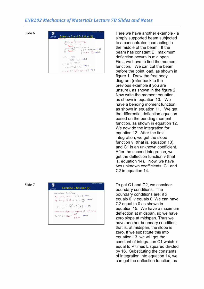
Here we have another example - a simply supported beam subjected to a concentrated load acting in the middle of the beam. If the beam has constant EI, maximum deflection occurs in mid span. First, we have to find the moment function. We can cut the beam before the point load, as shown in figure 1. Draw the free body diagram (refer back to the previous example if you are unsure), as shown in the figure 2. Now write the moment equation, as shown in equation 10. We have a bending moment function, as shown in equation 11. We get the differential deflection equation based on the bending moment function, as shown in equation 12. We now do the integration for equation 12. After the first integration, we get the slope function v’ (that is, equation 13), and C1 is an unknown coefficient. After the second integration, we get the deflection function v (that is, equation 14). Now, we have two unknown coefficients, C1 and C2 in equation 14.
Slide 7 ENR202 7b -- Slide No. 7
Exercise 2 Solution (2)
(15)
(16)
(17)
(18)
To get C1 and C2, we consider boundary conditions. The boundary conditions are: if x equals 0, v equals 0. We can have C2 equal to 0 as shown in equation 15. We have a maximum deflection at midspan, so we have zero slope at midspan. Thus we have another boundary condition; that is, at midspan, the slope is zero. If we substitute this into equation 13, we will get the constant of integration C1 which is equal to P times L squared divided by 16. Substituting the constants of integration into equation 14, we can get the deflection function, as
ENR202 Mechanics of Materials Lecture 7B Slides and Notes
shown in equation 17. We know that maximum deflection occurs at mid span. Substituting x equal to L divided by 2 into equation 17, we can have the maximum deflection at mid span equal to P times L cubed divided by 48EI, as shown in equation 18.
Slide 8 ENR202 7b -- Slide No. 8
Exercise 3 and Solution
Figure 1
Figure 2(19)
(20)
(21)
(22)
(23)
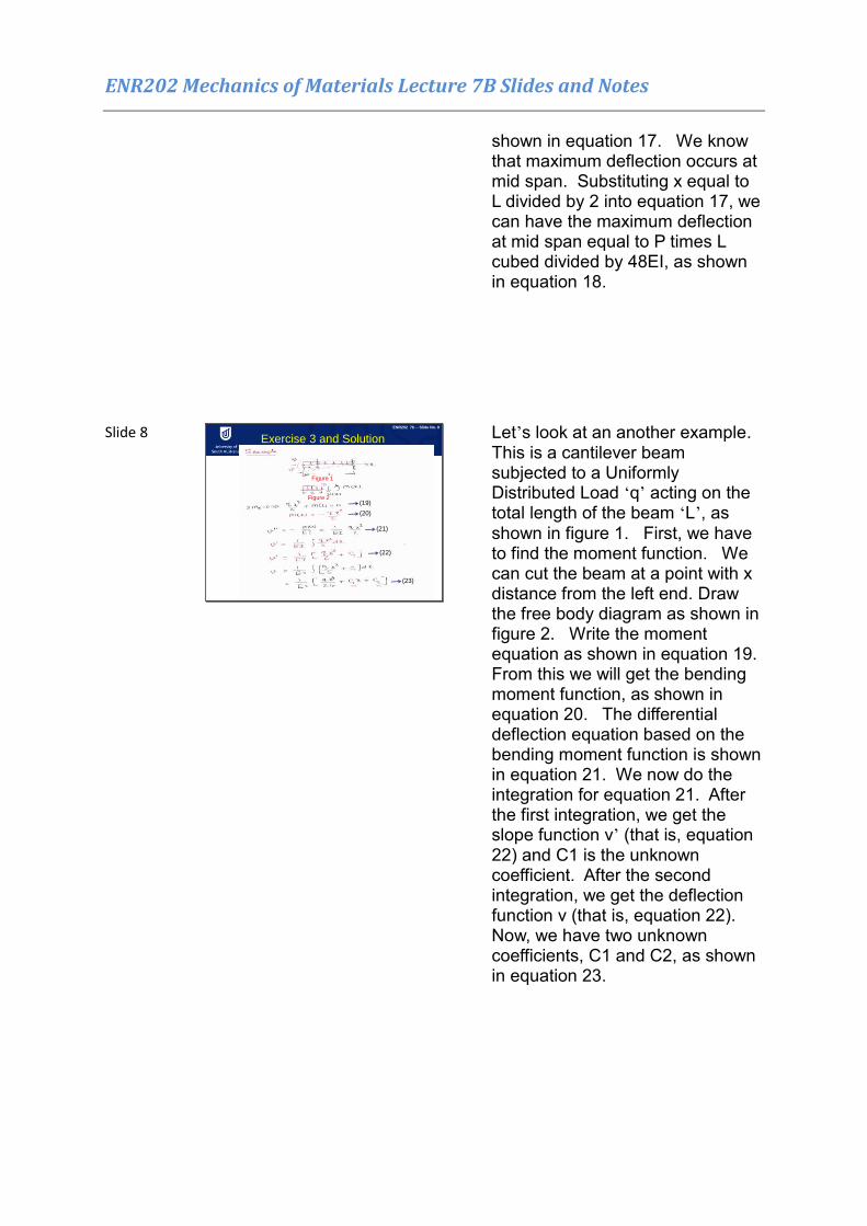
Let’s look at an another example. This is a cantilever beam subjected to a Uniformly Distributed Load ‘q’ acting on the total length of the beam ‘L’, as shown in figure 1. First, we have to find the moment function. We can cut the beam at a point with x distance from the left end. Draw the free body diagram as shown in figure 2. Write the moment equation as shown in equation 19. From this we will get the bending moment function, as shown in equation 20. The differential deflection equation based on the bending moment function is shown in equation 21. We now do the integration for equation 21. After the first integration, we get the slope function v’ (that is, equation 22) and C1 is the unknown coefficient. After the second integration, we get the deflection function v (that is, equation 22). Now, we have two unknown coefficients, C1 and C2, as shown in equation 23.

ENR202 Mechanics of Materials Lecture 7B Slides and Notes
Slide 9
ENR202 5b -- Slide No. 9
Exercise 3 solution (2)
(24)
(25)
(26)
To get C1 and C2, we consider the boundary conditions. The boundary conditions are: if x equals L, deflection is equal to zero and also slope v’ is equal to zero. Based on the second conditions, we can have C1 equal to minus q times L cubed divided by 6 as shown in equation (24). If we input the C1 value into the v equation (that is, equation 23), we can have C2 equal to q times L to the power of 4 divided by 8. Finally, we have the deflection function for the cantilever beam as shown in equation 25. Maximum deflection happens when x equal to 0, which means the free end. Substituting x equal to 0 into equation 25, we get the maximum deflection equal to q times L to the power of 4 divided by 8 times EI, as shown in equation 26.
Slide 10 ENR202 7b -- Slide No. 10
Exercise 4 and Solution
Figure 1
Figure 2(28)
(29)
(30)
(31)
(27)
Here is another example. Here we have a cantilever beam which is subjected to a concentrated load P at the free end. The length of the beam is ‘L’ as shown in figure 1. Cut the section from the free end at a distance x, and draw the free body diagram, as shown in figure 2. Write the moment equation, as shown in equation 27. Then we will get the bending moment function, as shown in equation 28. The differential deflection equation based on the bending moment function is shown in equation 29. Now do the integration for equation 29. After the first integration, we get the slope function v’ (that is, equation 30), and C1 is an unknown coefficient. After the second integration, we get the deflection function v (that is, equation 31). Now we have two unknown coefficients, C1 and
ENR202 Mechanics of Materials Lecture 7B Slides and Notes
C2, in equation 31.
Slide 11 ENR202 7b -- Slide No. 11
Exercise 4 solution (2)
(32)
(33)
(34)
(35)
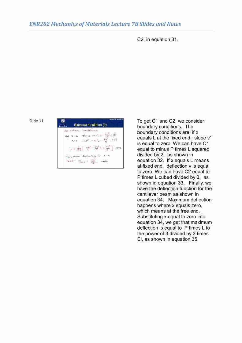
To get C1 and C2, we consider boundary conditions. The boundary conditions are: if x equals L at the fixed end, slope v’ is equal to zero. We can have C1 equal to minus P times L squared divided by 2, as shown in equation 32. If x equals L means at fixed end, deflection v is equal to zero. We can have C2 equal to P times L cubed divided by 3, as shown in equation 33. Finally, we have the deflection function for the cantilever beam as shown in equation 34. Maximum deflection happens where x equals zero, which means at the free end. Substituting x equal to zero into equation 34, we get that maximum deflection is equal to P times L to the power of 3 divided by 3 times EI, as shown in equation 35.

ENR202 Mechanics of Materials Lecture 7B Slides and Notes
Slide 12
ENR202 7b -- Slide No. 12
Summary of maximum deflection
This table summarises the deflections of simply supported beams or cantilever beams subjected to a concentrated load or Uniformly Distributed Load. As an engineer, it is important that you memorize these. There is no need to understand the development of all the formulas. However you need to know the length of the beam ‘L’ and the maximum deflection formulas, as shown in the table. Some hints which may help you remember the formulas are: Firstly, there is more deflection with a concentrated load than with a uniformly distributed load. Secondly, for a simply supported beam and a cantilever beam, the deflection for a UDL length will be L to the power of 4, and the deflection for a concentrated load will be L to the power of 3. Thirdly, we have EI in the denominator for all formulas. For the coefficients, you will have to memorise the numbers, such as 3, 8, 48, 384, and 5 (in the same way which you memorise a telephone number).
ENR202 Mechanics of Materials Lecture 7B Slides and Notes
Slide 13
Example 2: The simply supported beam shown in the figure is subjected to the concentrated force P. Determine the maximum deflection of the beam. EI is constant.
Exercise 5
ENR202 7b -- Slide No. 13
Figure 1
Figure 2
Figure 3
Figure 4
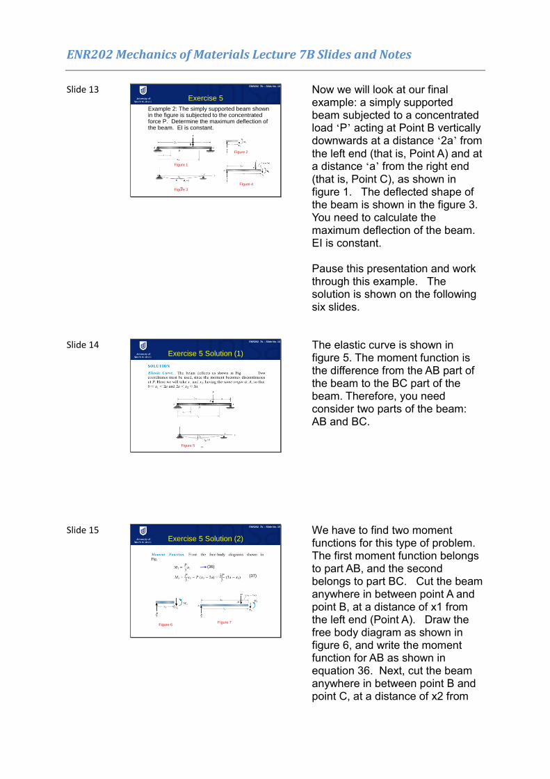
Now we will look at our final example: a simply supported beam subjected to a concentrated load ‘P’ acting at Point B vertically downwards at a distance ‘2a’ from the left end (that is, Point A) and at a distance ‘a’ from the right end (that is, Point C), as shown in figure 1. The deflected shape of the beam is shown in the figure 3. You need to calculate the maximum deflection of the beam. EI is constant. Pause this presentation and work through this example. The solution is shown on the following six slides.
Slide 14
Exercise 5 Solution (1)
ENR202 7b -- Slide No. 14
Figure 5
The elastic curve is shown in figure 5. The moment function is the difference from the AB part of the beam to the BC part of the beam. Therefore, you need consider two parts of the beam: AB and BC.
Slide 15 ENR202 7b -- Slide No. 15
Exercise 5 Solution (2)
Figure 6Figure 7
(36)
(37)
We have to find two moment functions for this type of problem. The first moment function belongs to part AB, and the second belongs to part BC. Cut the beam anywhere in between point A and point B, at a distance of x1 from the left end (Point A). Draw the free body diagram as shown in figure 6, and write the moment function for AB as shown in equation 36. Next, cut the beam anywhere in between point B and point C, at a distance of x2 from

ENR202 Mechanics of Materials Lecture 7B Slides and Notes
left end (point A) and draw the free body diagram as shown in figure 7. Now work out the moment function for part BC, as shown in equation 37.
Slide 16
-
-
-
-
-
-
Exercise 5 Solution (3)
ENR202 7b -- Slide No. 16
We get the differential deflection equation for AB based on the bending moment function M1, as per equation 36 in the previous slide. Now we now do the integration for this equation. After the first integration, we get the slope function v’ (equation 1). After the second integration, we get the deflection function v (equation 2). Now, we have two unknown coefficients in equation 2, C1 and C2. We get the differential deflection equation for part BC of the beam based on the bending moment function M2, as per equation 37 on the previous slide. We now do the integration for this equation. After the first integration, we get the slope function v’ (that is, equation 3). After the second integration, we get the deflection function v (that is, equation 4). Now, we have two more unknown coefficients in equation 4, C3 and C4.
ENR202 Mechanics of Materials Lecture 7B Slides and Notes
Slide 17
-
- -
- -
ENR202 7b -- Slide No. 17
Exercise 5 Solution (4)
(5)
(6)
(7)
(8)
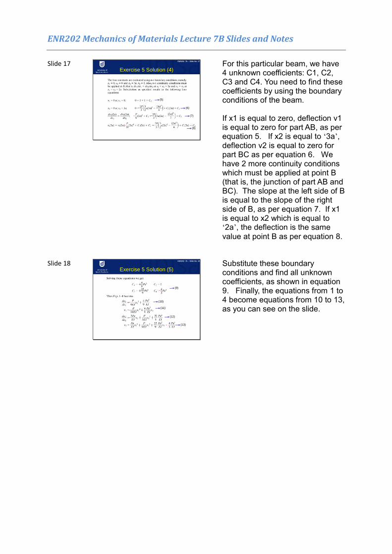
For this particular beam, we have 4 unknown coefficients: C1, C2, C3 and C4. You need to find these coefficients by using the boundary conditions of the beam. If x1 is equal to zero, deflection v1 is equal to zero for part AB, as per equation 5. If x2 is equal to ‘3a’, deflection v2 is equal to zero for part BC as per equation 6. We have 2 more continuity conditions which must be applied at point B (that is, the junction of part AB and BC). The slope at the left side of B is equal to the slope of the right side of B, as per equation 7. If x1 is equal to x2 which is equal to ‘2a’, the deflection is the same value at point B as per equation 8.
Slide 18
-
-
-
-
-
ENR202 7b -- Slide No. 18
Exercise 5 Solution (5)
(9)
(13)
(12)
(11)
(10)
Substitute these boundary conditions and find all unknown coefficients, as shown in equation 9. Finally, the equations from 1 to 4 become equations from 10 to 13, as you can see on the slide.
ENR202 Mechanics of Materials Lecture 7B Slides and Notes
Slide 19
-
ENR202 7b -- Slide No. 19
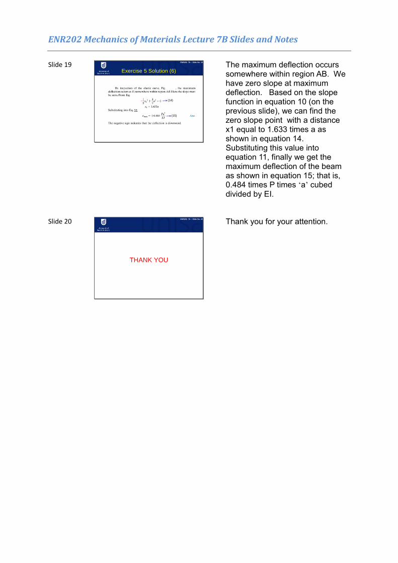
Exercise 5 Solution (6)
11
(15)
(14)
The maximum deflection occurs somewhere within region AB. We have zero slope at maximum deflection. Based on the slope function in equation 10 (on the previous slide), we can find the zero slope point with a distance x1 equal to 1.633 times a as shown in equation 14. Substituting this value into equation 11, finally we get the maximum deflection of the beam as shown in equation 15; that is, 0.484 times P times ‘a’ cubed divided by EI.
Slide 20
THANK YOU
ENR202 7b -- Slide No. 20
Thank you for your attention.
Related Documents