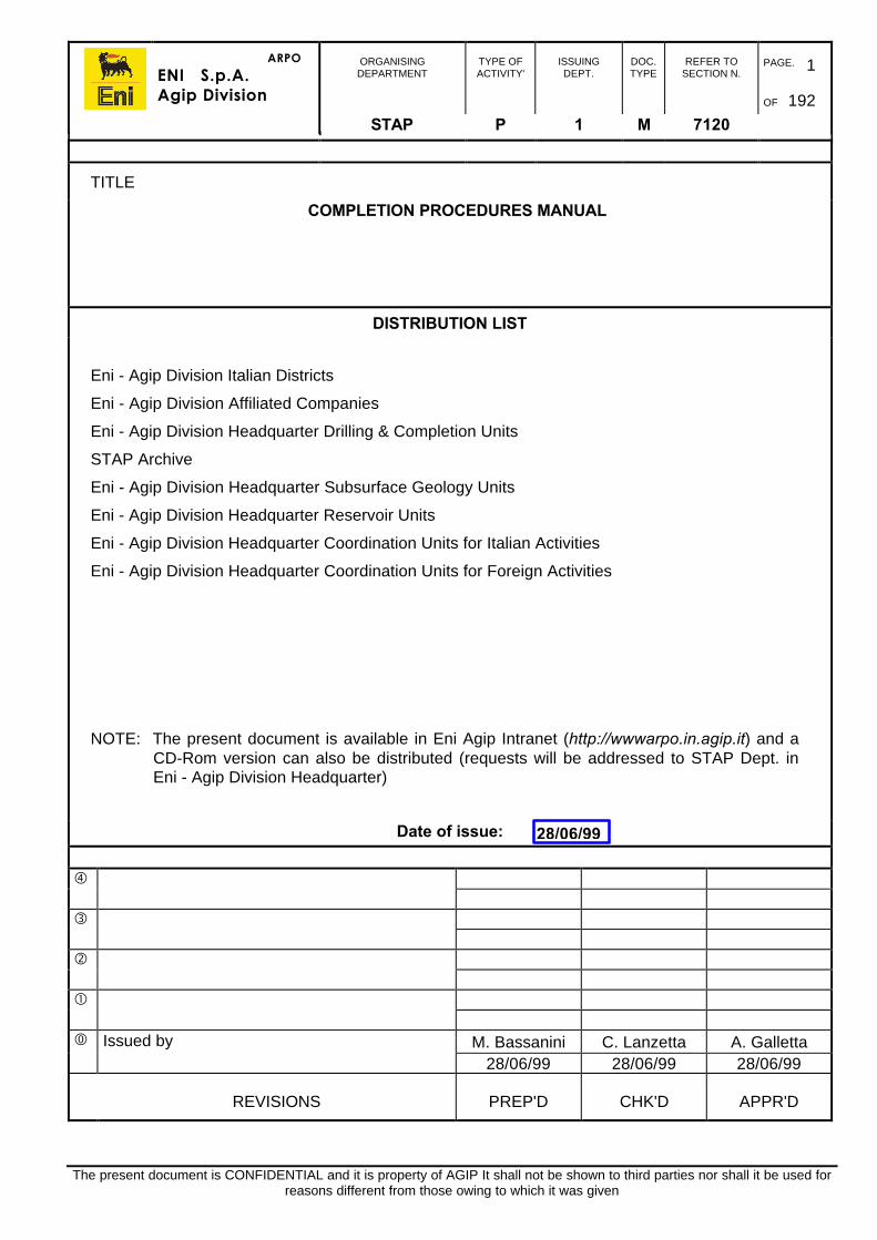
ARPO ENI S.p.A. Agip Division ORGANISING DEPARTMENT TYPE OF ACTIVITY' ISSUING DEPT. DOC. TYPE REFER TO SECTION N. PAGE. 1 OF 192 STAP P 1 M 7120 The present document is CONFIDENTIAL and it is property of AGIP It shall not be shown to third parties nor shall it be used for reasons different from those owing to which it was given TITLE COMPLETION PROCEDURES MANUAL DISTRIBUTION LIST Eni - Agip Division Italian Districts Eni - Agip Division Affiliated Companies Eni - Agip Division Headquarter Drilling & Completion Units STAP Archive Eni - Agip Division Headquarter Subsurface Geology Units Eni - Agip Division Headquarter Reservoir Units Eni - Agip Division Headquarter Coordination Units for Italian Activities Eni - Agip Division Headquarter Coordination Units for Foreign Activities NOTE: The present document is available in Eni Agip Intranet (http://wwwarpo.in.agip.it) and a CD-Rom version can also be distributed (requests will be addressed to STAP Dept. in Eni - Agip Division Headquarter) Date of issue: Issued by M. Bassanini C. Lanzetta A. Galletta 28/06/99 28/06/99 28/06/99 REVISIONS PREP'D CHK'D APPR'D 28/06/99

ENI - Completion Procedures Manual
Oct 04, 2014
Welcome message from author
This document is posted to help you gain knowledge. Please leave a comment to let me know what you think about it! Share it to your friends and learn new things together.
Transcript
ARPO
ENI S.p.A.Agip Division
ORGANISINGDEPARTMENT
TYPE OFACTIVITY'
ISSUINGDEPT.
DOC.TYPE
REFER TOSECTION N.
PAGE. 1
OF 192
STAP P 1 M 7120
The present document is CONFIDENTIAL and it is property of AGIP It shall not be shown to third parties nor shall it be used forreasons different from those owing to which it was given
TITLE
COMPLETION PROCEDURES MANUAL
DISTRIBUTION LIST
Eni - Agip Division Italian Districts
Eni - Agip Division Affiliated Companies
Eni - Agip Division Headquarter Drilling & Completion Units
STAP Archive
Eni - Agip Division Headquarter Subsurface Geology Units
Eni - Agip Division Headquarter Reservoir Units
Eni - Agip Division Headquarter Coordination Units for Italian Activities
Eni - Agip Division Headquarter Coordination Units for Foreign Activities
NOTE: The present document is available in Eni Agip Intranet (http://wwwarpo.in.agip.it) and aCD-Rom version can also be distributed (requests will be addressed to STAP Dept. inEni - Agip Division Headquarter)
Date of issue:
�
�
�
�
� Issued by M. Bassanini C. Lanzetta A. Galletta28/06/99 28/06/99 28/06/99
REVISIONS PREP'D CHK'D APPR'D
28/06/99
ARPO
ENI S.p.A.Agip Division
IDENTIFICATION CODE PAGE 2 OF 192
REVISIONSTAP -P-1-M-7120 0
INDEX
1. INTRODUCTION 9
1.1. PURPOSE OF THE MANUAL 9
1.2. IMPLEMENTATION 9
1.3. UPDATING, AMENDMENT, CONTROL & DEROGATION 9
2. RESPONSIBILITIES 10
2.1. DRILLING COMPLETION AND WORKOVER MANAGER 10
2.2. WELL OPERATIONS SUPERINTENDENT 11
2.3. COMPLETION AND WORKOVER ENGINEER 11
2.4. FLUIDS SPECIALIST 12
2.5. OFFSHORE INSTALLATION MANAGER (OIM) 13
2.6. WELL OPERATIONS SUPERVISOR 13
2.7. PRODUCTION SUPERVISOR 14
3. DOCUMENTATION 15
3.1. PRELIMINARY INFORMATION 15
3.2. WELLSITE REPORTS 15
3.3. FEED BACK REPORTS 15
3.4. OTHER REPORTS 16
3.5. PERMIT PROCEDURES 163.5.1. Guidance For Permits 16
3.6. WELL HANDOVER PROCEDURES 173.6.1. Well Handover Certificate 173.6.2. Well Intervention Handover Certificate 18
4. HOLE PREPARATIONS 23
4.1. PRELIMINARY CHECKS 23
4.2. WELL CLEAN UP PROCEDURES 23
4.3. BOP STACK CONFIGURATION AND TESTING 24
4.4. WELL CONTROL 24
ARPO
ENI S.p.A.Agip Division
IDENTIFICATION CODE PAGE 3 OF 192
REVISIONSTAP -P-1-M-7120 0
4.5. OIL BASED MUD DISPLACEMENT 244.5.1. Displacement Objectives 244.5.2. Logistical Considerations 254.5.3. Drilling Fluid Preparation 254.5.4. Surface Equipment Preparation 264.5.5. Well Clean Up Pill Sequence 264.5.6. Pill Functions 274.5.7. Pit Requirements 274.5.8. Pumping Sequence 27
4.6. DISPLACEMENT OF WATER BASED MUDS 284.6.1. Drilling Fluid Preparation 284.6.2. Surface Equipment Preparation 284.6.3. Well Clean Up Pill Sequence 284.6.4. Pill Functions 294.6.5. Pit Requirements 294.6.6. Pumping Sequence 29
4.7. COMPLETION AND WORKOVER FLUIDS 294.7.1. Brines Transportation 294.7.2. Completion And Workover Fluid Quality 30
4.8. FILTRATION SYSTEMS 304.8.1. Fluid Cleanliness 30
4.9. LOST CIRCULATION 314.9.1. Viscous Pills 314.9.2. Sized Salt Pills 314.9.3. Calcium Carbonate Pills 32
4.10. CASING GAUGE CONTROL 33
5. PERFORATING PROCEDURES 34
5.1. GENERAL 34
5.2. METHODS OF PERFORATING 35
5.3. GENERAL SAFETY PROCEDURES 35
5.4. WIRELINE CONVEYED PERFORATING 375.4.1. Casing Guns Run In Overbalance 375.4.2. Perforating Procedures For Through Tubing Conveyed Guns 38
5.5. SAFE SYSTEM 395.5.1. SAFE System Description (Slapper Activated Firing Explosives) 40
5.6. TCP PROCEDURES 405.6.1. Well Preparation for TCP Operations 415.6.2. Ancillary TCP Equipment 415.6.3. Firing Systems for TCP Operations 435.6.4. General TCP Safety Precautions and Running Procedures 445.6.5. Firing Procedure for Tubing Installed Pressure Activated Head 455.6.6. Firing Procedure for Wireline Installed Pressure Activated Head 455.6.7. Firing Procedure for Mechanical Impact Activated Head 455.6.8. Firing Procedure for Electrically Activated TCP Guns 465.6.9. Procedure For TCP Anchor Running 475.6.10. TCP Anchor Firing Head Installation 48
ARPO
ENI S.p.A.Agip Division
IDENTIFICATION CODE PAGE 4 OF 192
REVISIONSTAP -P-1-M-7120 0
5.7. MISFIRE PROCEDURES 515.7.1. Mechanical Firing Head 515.7.2. Hydraulic Firing Head 525.7.3. Fixed Hydraulic Firing Head 535.7.4. Retrievable Hydraulic Firing Head 53
5.8. COILED TUBING PERFORATING 53
6. GRAVEL PACKING PROCEDURES 54
6.1. GRAVEL PLACEMENT OBJECTIVES 54
6.2. SCREEN SIZE 54
6.3. GRAVEL CALCULATIONS 556.3.1. Sand Volume Required 556.3.2. Carrier Fluid Volume 56
6.4. COMMON GRAVEL PACK PROCEDURES 56
6.5. OPEN HOLE GRAVEL PACK PROCEDURE 57
6.6. CASED HOLE GRAVEL PACK PROCEDURE 59
7. PACKER INSTALLATION 64
7.1. HOLE PREPARATION 64
7.2. WIRELINE PACKER SETTING PROCEDURE 647.2.1. Running Procedure 65
7.3. TUBING INSTALLED PACKER SETTING PROCEDURE 667.3.1. Workstring Running Procedure 667.3.2. Completion String Running Procedure 67
8. COMPLETION INSTALLATION 68
8.1. CARBON STEEL AND PLASTIC COATED TUBING 68
8.2. CHROME TUBULARS 688.2.1. Transportation 688.2.2. Transport From The Mill 698.2.3. Road Transport 698.2.4. Marine Transport 698.2.5. Handling At The Wellsite 698.2.6. Thread Compounds 718.2.7. Running Chrome Tubulars 728.2.8. Retrieving Chrome Tubulars 73
8.3. EQUIPMENT PRE-INSTALLATION PROCEDURES 748.3.1. Material Requisition Lists 748.3.2. Completion Sub Assemblies 748.3.3. Tubing Hanger 758.3.4. Landing Joint 758.3.5. Control Line 758.3.6. Xmas Tree 758.3.7. Flowline 76
ARPO
ENI S.p.A.Agip Division
IDENTIFICATION CODE PAGE 5 OF 192
REVISIONSTAP -P-1-M-7120 0
8.4. COMPLETION ASSEMBLIES 768.4.1. Workshop Make-up and Test Procedures 768.4.2. Sub-Surface Safety Valves 768.4.3. Wireline Nipple Assemblies 778.4.4. Side Pocket Mandrels 77
8.5. COMPLETION RUNNING PROCEDURES 788.5.1. General 788.5.2. Running Procedure 798.5.3. TRSCSSV Installation Procedure 808.5.4. WRSCSSV Installation Procedure 81
8.6. XMAS TREE INSTALLATION 828.6.1. Installation Procedures 82
8.7. POST COMPLETION TEST PROCEDURES 838.7.1. SCSSV Test Procedure 838.7.2. Xmas Tree Valve Test Procedure 83
9. GAS LIFT INSTALLATION 85
9.1. MANDREL INSTALLATION 859.1.1. SPM Installation Procedure 859.1.2. Gas Lift Valve Installation Procedure 87
9.2. UNLOADING PROCEDURE 88
9.3. TROUBLESHOOTING 88
10. DOWNHOLE PUMP INSTALLATION 89
10.1. ELECTRICAL SUBMERSIBLE PUMPS 8910.1.1. Handling 8910.1.2. Installation 8910.1.3. Pulling Procedure 9310.1.4. Troubleshooting 93
10.2. ROD PUMPS 9610.2.1. Completion Installation 9610.2.2. Tubing String Installation 9610.2.3. Rod Installation 98
10.3. HYDRAULIC PUMPS 9810.3.1. Jet Pump 9910.3.2. Turbine Pump 10110.3.3. Piston Pump 101
ARPO
ENI S.p.A.Agip Division
IDENTIFICATION CODE PAGE 6 OF 192
REVISIONSTAP -P-1-M-7120 0
11. SUBSEA COMPLETIONS 102
11.1. SUBSEA EQUIPMENT PRE-DEPLOYMENT TESTING 10311.1.1. Guidewire Establishment Tool 10311.1.2. Guidewire Latchess 10311.1.3. Diverless Guideposts 10311.1.4. Casing Hanger Elevation Test Tool 10411.1.5. Tubing Hanger System 10411.1.6. Tubing Hanger Running/Orientation Tools 10611.1.7. Tubing Hanger Verification Tool 10911.1.8. Tubing Hanger Isolation Plugs 11011.1.9. Subsea Tree And Workover Equipment 11011.1.10. Install the LRP/TRT onto the XT 11511.1.11. Production Riser 11711.1.12. Surface Xmas Tree 118
11.2. DEPLOYMENT PROCEDURES 11811.2.1. Running The Completion And Tubing Hanger 11811.2.2. Pull The Drilling BOPs 120
11.3. WORKOVER AND PRODUCTION CONTROLS SYSTEM PRE-DEPLOYMENT TESTING 12011.3.1. Workover Controls Equipment 12011.3.2. Production Controls Equipment 12011.3.3. WOCS Pre-Deployment Testing 12111.3.4. Production Controls Pre-Deployment Testing 12411.3.5. Function Test using SEM B 12811.3.6. Pressure Test Tree Valves 131
11.4. RUNNING THE SUBSEA XMAS TREE 13611.4.1. Unplugging The Well 13611.4.2. Perforating And Well clean-Up 137
11.5. PULLING THE LRP 13711.5.1. Disconnect The LRP And Tree Running Tool 137
11.6. DEPLOYMENT OF THE TREE CAP 138
11.7. DEPLOYMENT AFTER COMMISSIONING ACTIVITIES 138
12. WELL UNLOADING 139
12.1. UNLOADING BY CIRCULATION 139
12.2. UNLOADING BY BULLHEADING 141
12.3. UNLOADING BY COILED TUBING 141
13. COILED TUBING OPERATIONS 14213.1.1. PREPARATION 142
13.2. SAFETY CONSIDERATIONS 14213.2.1. Tubing 14313.2.2. Risers and BOPs 14313.2.3. H2S Considerations 144
13.3. PERMIT REQUIREMENTS 144
ARPO
ENI S.p.A.Agip Division
IDENTIFICATION CODE PAGE 7 OF 192
REVISIONSTAP -P-1-M-7120 0
13.4. RIG UP PROCEDURES 14513.4.1. Equipment Preparation and Siting 14513.4.2. Coiled Tubing Rig-Up 14513.4.3. Pressure Testing 14613.4.4. Treating Lines 14813.4.5. Injector Frame 14813.4.6. Rigging Down 148
13.5. RUNNING PROCEDURES 149
13.6. OPERATING PROCEDURES 15013.6.1. Gas Lifting 15013.6.2. Well Treatment 15113.6.3. Sand Cleanout 153
14. NITROGEN PROCEDURES 155
14.1. PREPARATION 155
14.2. SAFETY CONSIDERATIONS 155
14.3. NITROGEN HANDLING 15614.3.1. Safety Equipment 15614.3.2. Safety Data Sheets 15714.3.3. Pressurised Lines 157
14.4. RIG-UP PROCEDURES 15714.4.1. Equipment Preparation and Siting 15714.4.2. Equipment Rig-up 15714.4.3. Pressure Testing 15814.4.4. Treating Lines 15814.4.5. Rigging Down 158
14.5. NITROGEN TREATMENT PROCEDURES 15914.5.1. Pressures 15914.5.2. Pump Rates 15914.5.3. Coiled Tubing Gas Lift 15914.5.4. Nitrogen Cushion - Tubing Conveyed Perforation 16014.5.5. Nitrified Treatment 161
14.6. NITROGEN TECHNICAL INFORMATION 161
14.7. EMERGENCY PROCEDURES (During Nitrogen Operations) 16214.7.1. Production Shutdown 16214.7.2. General Platform Alarm 16214.7.3. Prepare to Abandon Platform 16214.7.4. Liquid Nitrogen Spill 16314.7.5. Injury to Personnel 163
15. STIMULATION PROCEDURES 164
15.1. INTRODUCTION 164
15.2. SAFETY CONSIDERATIONS 16415.2.1. Chemical Handling 16515.2.2. Pressure 166
15.3. PERMIT REQUIREMENTS 167
15.4. RIG-UP PROCEDURES 16715.4.1. Equipment Preparation and Siting 16715.4.2. Equipment Rig-Up 168
ARPO
ENI S.p.A.Agip Division
IDENTIFICATION CODE PAGE 8 OF 192
REVISIONSTAP -P-1-M-7120 0
15.4.3. Pressure Testing 16815.4.4. Treating Lines 16915.4.5. Rigging Down 169
15.5. TREATMENT PROCEDURES 16915.5.1. Matrix Acidising 17015.5.2. Fracture Acidising 17015.5.3. Acid Wash 17015.5.4. Scale Dissolver 17015.5.5. Bullhead 17115.5.6. Coiled Tubing 17115.5.7. Asphaltene and Wax/Dissolvers 171
15.6. STIMULATION TECHNICAL INFORMATION 17115.6.1. Factors Affecting Acid Reaction 17215.6.2. Acid Properties 174
15.7. ACID ADDITIVES 175
APPENDIX A - REPORT FORMS 177
A.1. Initial Activity Report (ARPO 01) 177
A.2. Daily Report (ARPO 02) 178
A.3. Cementing Job Report (ARPO 04B) 179
A.4. Waste Report (ARPO 6) 180
A.5. Perforating Report (ARPO 07) 181
A.6. Gravel Pack Report (ARPO 08) 182
A.7. Matrix Stimulation Report (ARPO 09) 183
A.8. Well Problem Report (ARPO 13) 184
A.9. Malfunction & Failure Report(FB-1) 185
A.10. Contractor Evaluation (FB-2) 186
APPENDIX B - ABBREVIATIONS 187
APPENDIX C - BIBLIOGRAPHY 192
ARPO
ENI S.p.A.Agip Division
IDENTIFICATION CODE PAGE 9 OF 192
REVISIONSTAP-P-1-7120 0
1. INTRODUCTION
1.1. PURPOSE OF THE MANUAL
The purpose of the Completions Procedures Manual is to guide technicians and engineers,involved in Eni-Agip’s Drilling & Completion worldwide activities, through the Proceduresand the Technical Specifications for general completion operations which are part of theCorporate Standards.
Such Corporate Standards define the requirements, methodologies and rules that enable tooperate uniformly and in compliance with the Corporate Company Principles. This, however,still enables each individual Affiliated Company the capability to operate according to locallaws or particular environmental situations.
The final aim is to improve performance and efficiency in terms of safety, quality and costs,while providing all personnel involved in Drilling & Completion activities with commonguidelines in all areas worldwide where Eni-Agip operates.
It is intended to guide users towards using procedures which have been found to providethe most efficient and cost effective operations.
1.2. IMPLEMENTATION
The policies included in this manual apply to all Eni-Agip Division and Affiliates operations.
All supervisory and technical personnel engaged in Eni-Agip’s completion and workoveroperations are expected to make themselves familiar with these and comply with thepolicies and procedures specified and contained in this manual.
1.3. UPDATING, AMENDMENT, CONTROL & DEROGATION
This is a ‘live’ controlled document and, as such, it will only be amended and improved bythe Corporate Company, in accordance with the development of Eni-Agip Division andAffiliates operational experience. Accordingly, it will be the responsibility of everyoneconcerned in the use and application of this manual to review the policies and relatedprocedures on an ongoing basis.
Locally dictated derogations from the manual shall be approved solely in writing by theManager of the local Drilling and Completion Department (D&C Dept.) after theDistrict/Affiliate Manager and the Corporate Drilling & Completion Standards Department inEni-Agip Division Head Office have been advised in writing.
The Corporate Drilling & Completion Standards Department will consider such approvedderogations for future amendments and improvements of the manual, when the updating ofthe document will be advisable.
ARPO
ENI S.p.A.Agip Division
IDENTIFICATION CODE PAGE 10 OF 192
REVISIONSTAP-P-1-7120 0
2. RESPONSIBILITIES
The following job descriptions outline the individual responsibilities and duties of specifickey personnel involved in Eni-Agip Completion operations. These are generalised summaryof the individual responsibilities and duties which are specific to completion operations andas such augment, but do not supersede their current employer’s approved job descriptions.
2.1. DRILLING COMPLETION AND WORKOVER MANAGER
The Drilling/Completions and Workover Manager reports directly to the District Manager andsupervises the Well Operations Superintendent, Completions and WorkoverSuperintendent, Drilling Engineering/Completions and Workover Engineering.
His duties include the following:
• Ensuring the definition of scope of work and requisitioning of drilling andcompletion/workover contracts are correctly processed by the contractsdepartment and approved first by the District Manager, in order to comply withtime schedule, quality and technical conditions as defined in the programme.
• Ensuring the pre-qualification and technical tender evaluation phases complywith company policies and procedures and to provide the Contracts departmentwith all technical details necessary for a thorough commercial evaluation.
• Approving the completions programmes, ensuring they fully meet the prognosistarget, pursuing the best results in terms of safety, time schedule and costeffectiveness.
• Managing day-to-day completions operations, co-ordinating the activities ofcontractors and units/positions involved, in order to guarantee that operationsmeet the company policies and standards.
• Controlling operational costs and provides the technical approval for invoicepayment. Verifies the consistency of the expenditure with AFEs and with theadministration validity of the contracts.
• Liaising, timely and effectively, with the regulatory bodies in order to obtainconsent for well related operations.
• Instituting, monitoring and reviewing completions safety policies within theSafety Management System, in order to maximise effectiveness and safety ofthe operations.
ARPO
ENI S.p.A.Agip Division
IDENTIFICATION CODE PAGE 11 OF 192
REVISIONSTAP -P-1-M-7120 0
2.2. WELL OPERATIONS SUPERINTENDENT
The Well Operations Superintendent reports to the Drilling, Completion and WorkoverManager and supervises rig site supervisors.
His duties include the following:
• Ensuring operational progress follows the approved well programme andprovides technical advice to the rig site on a daily basis, as required.
• Ensuring the correct scheduling of completion materials and services, provides atimely supply to the rigs while optimising the cost of transport, materials andmanpower within established programmes and budgets.
• Administering service contracts, providing the technical control of contractorperformance giving the first authorisation to the payment of invoices andensuring the control of current total expenditure on each contract.
• Ensuring that operations comply with current legislation and companystandards.
• Preparing scopes of work and technical specification for services to be tenderedand review those for services and equipment.
• Providing technical advice during pre-qualification and tender evaluationphases, in order to ensure that the selection of contractors and suppliers fullymeet technical targets and company standards.
• Providing timely and accurate requisitions for all services and materials relevantto well operations.
• Ensuring, in liaison with AQS, the correct interface of the Contractor’sprocedures are to Eni-Agip’s policies and procedures.
• Ensuring simultaneous completion and production procedures are reviewed.
2.3. COMPLETION AND WORKOVER ENGINEER
Reports to the Drilling, Completion and Workover Manager.
His duties include the following:
• Preparing and reviewing technical specifications and scopes of work forequipment to be tendered and services for completion, workover, wireline andwell testing operations.
• Co-operating with the Well Operations Superintendent for providing adviceduring pre-qualification and tender evaluation phases, in order to ensure that theselection of contractors and suppliers fully meet technical targets and companystandards.
• Supplying well cost estimates for future operations budgets and currentoperations AFEs, ensuring the reliability of the data provided.
• Contributing, in liaison with the Petroleum Engineer and with the ReservoirEngineers, to the planning of development projects, providing technical input tothe project teams, in order to optimise cost and effectiveness of the project.
• Monitoring, in liaison with the Petroleum Engineer and with the ReservoirEngineers, the performance of wells and reservoirs, in order to provide technicalexpertise and advice for identifying and initiating enhancements to wellpotential.
ARPO
ENI S.p.A.Agip Division
IDENTIFICATION CODE PAGE 12 OF 192
REVISIONSTAP -P-1-M-7120 0
• Appraising new completion, workover, wireline and well testing technology andproducts to determine their application to Eni-Agip’s completion operations, inorder to improve time cost performance and safety conditions.
• Preparing and reviewing completion, workover, wireline and well testingprogrammes and final reports and to ensure the production of adequatefeedback about the operations as per the Safety Management System corporaterequirements.
• Reviewing daily the operations versus the programme, providing a thoroughinvestigation of operational times.
• Providing engineering assistance to the Well Operations Superintendent in thefollow up of operations.
• Providing reports and analysis on the operated and non-operated activities forpresentation, meetings and reporting to the management and to ensure theoperational feedback reporting system is consistent with Eni-Agip and corporaterequirements.
• Assisting his supervisor in contacts with partners and regulatory bodiesproviding the necessary documentation and reports.
• Providing the monthly updates on the variance between actual and estimatedexpenditures for each job centre for each class of cost, also to liaise with theCompletion/Workover Superintendent, in order to update the expenditure oneach contract.
• Ensuring the production and review of the Completions Procedure Manual inorder to comply with company policies and the current legislation.
2.4. FLUIDS SPECIALIST
Reports to the Drilling, Completions and Workover Manager for routine operational matters.
His duties include the following:
• Preparing technical specifications for tenders.• Advising on pre-qualifications and tender evaluations exercises.• Preparing programmes ensuring the compliance with regulatory requirements.• Ensuring the compilation of final fluids reports and the feedback documents
relevant to the activities under his scope of work.• Maintaining up to date knowledge of the technical and regulatory evolution’s for
the activities under his scope of work.• Liaising with logistics department for ensuring the provision of services,
transportation and materials to well site.• Liaise with the appropriate service companies and suppliers on a daily basis.
ARPO
ENI S.p.A.Agip Division
IDENTIFICATION CODE PAGE 13 OF 192
REVISIONSTAP -P-1-M-7120 0
2.5. OFFSHORE INSTALLATION MANAGER (OIM)
If applicable, his duties include the following:
• Reporting directly to Asset Operations Manager.• Co-ordinating and supervising all operations on the installation. The senior
representatives for each discipline are responsible for the activities of their owndiscipline and must keep the OIM informed on their own respective operations.The Production Supervisor will keep the OIM informed on the status ofproduction operations.
• Authorise all work permits in accordance with the Permit to Work System, andwill ensure countersignature by the Well Operations Supervisor, or otherDiscipline Heads.
• For completion operations, he will delegate responsibility to the Well OperationsSupervisor or another Company Representative (e.g. Production Supervisor) asdictated by asset ownership or control at the time of the ongoing operations.
• Is responsible for the actions to be followed under the various installationoperating modes. The OIM will require advice from the WellOperations/Production Supervisor or other Discipline Heads, e.g. MaintenanceSupervisor, etc.
2.6. WELL OPERATIONS SUPERVISOR
Represents Eni-Agip’s interests on the installation with respect to the Drilling Contractor andService Companies.
The Senior Well Operations Supervisor is directly responsible for the drilling and completionequipment and all operations conducted during the drilling completion and workover phase.
His duties include the following:
• Ensuring all Company policies relating to drilling and completing operations andemergency situations are adhered to at all times for the safety of personnel, rigequipment, well stability and control.
• Directing the Drilling Contractor and Service Company representatives in theoperations to be performed and supervises the conduct of the operations.
• Ensuring all operations, detailed in the Drilling and Completion Programme, areperformed efficiently and safely using the procedures detailed in the programmeand/or Completion Procedures Manual.
• Responsibility for the Hot Permit System when ‘hot work’ is being conducted inthe drilling module.
• Requisitioning the equipment and materials required to complete the operations.He will requisition the materials when appropriate and liaise with the Completionand Workover Superintendent to ensure arrival at the rig-site in ample time toallow inspection and preparation prior to use.
• Ensuring all tools are suitable for purpose, inspected and dressed prior torunning in the well.
• Introducing changes to the Drilling and Completion Programme but only in anemergency or when operating conditions do not allow for communication withthe Drilling and completion Workover Department.
ARPO
ENI S.p.A.Agip Division
IDENTIFICATION CODE PAGE 14 OF 192
REVISIONSTAP -P-1-M-7120 0
• Ensuring all reports required, are accurate in content and are submitted asrequired. Reporting requirements are outlined in section 3.
• Liaising with the OIM, Company Production Supervisor, and other operationalHeads on a daily basis to discuss operational considerations and the possibleimpact on the other operations.
• Supervising and directs well control operations in accordance with the Eni-AgipWell Control Manual.
• Liaising with the OIM to give advice on what actions to take, if any of thePlatform Operating Modes are associated with the drilling operation, or arisefrom operations in the drilling module.
• On completion of the programme, i.e. Xmas tree is secured with all operationscompleted, officially handing over the well to the Production Department(Production Supervisor). Both parties must sign the relevant well handoverdocument.
• Co-ordinating all completion activities including wireline and/or coiltubing/nitrogen, acid stimulation, perforating as well as all preliminary pressuretesting of equipment.
• Ensuring the safe and correct installation of all tubulars and completion sub-assembly components, i.e. in the correct order and proper depth as per thecompletion programme.
2.7. PRODUCTION SUPERVISOR
Reports to the Company Production Superintendent (Office).
His duties include the following:
• Representing Eni-Agip’s interests on the platform with respect to production,and when dealing with service companies involved with operations during theproduction phase.
• Ensuring that, during heavy lift operations such as handling Xmas trees etc.,neighbouring wells are closed-in to minimise risk to wellheads, flowlines,production equipment, the platform and personnel.
• Informing the Well Operations Supervisor, OIM and other Discipline Heads onthe status of the production operations and the possible impact on otheroperations in general.
• Prior to a workover being carried out, handing the well over toDrilling/Completion (Well Operations Supervisor) stating the exact condition ofthe well. Both parties must sign the handover document.
ARPO
ENI S.p.A.Agip Division
IDENTIFICATION CODE PAGE 15 OF 192
REVISIONSTAP-P-1-7120 0
3. DOCUMENTATION
This section outlines the documentation necessary for conducting efficient completionoperations and reporting of these operations.
3.1. PRELIMINARY INFORMATION
Before performing any well operations the following documentation and information must beavailable:
A detailed programme including:
• Name of Field• Name of Well• Well Code• Well Co-ordinates (wellhead and bottom hole)• Cost Centre Number• RKB Elevation• Completion String Schematic (completion components ID, length, tubing
size/weight, depths, etc.)• Intervals to be perforated• Specifications of Completion Equipment.
3.2. WELLSITE REPORTS
To schedule future operational programmes, all operations must be properly documentedand kept on file to maintain the history of operations performed on any well.
The operations performed during rig operations (completion string gauging, packer setting,etc.) will be reported in the Daily Well Report. This and other service reports for gravelpacking, stimulation and other well operations are shown in Appendix A.
It is responsibility of the Well Operations Supervisor to compile and forward the reports(indicated below) to the Well Operations Superintendent. The Superintendent will thencheck and approve the reports before distribution and filing.
3.3. FEED BACK REPORTS
The following reports are compiled at the end of the operations:
a) FB-01 Report on Equipment Damage and Malfunctions
b) FB-02 Service Company Evaluation Report
Refer to Appendix A for copies of appropriate reports.
ARPO
ENI S.p.A.Agip Division
IDENTIFICATION CODE PAGE 16 OF 192
REVISIONSTAP -P-1-M-7120 0
3.4. OTHER REPORTS
The Eni-Agip Representative must sign the Service Reports of the Service Companieswhich must include the following information :
• Name of Well• Name of Field• Order Number• Date• Personnel and equipment used• Description of the operations conducted• Starting and completion dates for service company charges.
3.5. PERMIT PROCEDURES
No work can be performed without a valid permit to work. All requirements as laid out in theCompany Permit to Work Procedures must be adhered to at all times. Although theoperation of a permit system is the responsibility of the installation manager, safe operatingpractice is compulsory and the responsibility of all personnel involved in completionoperations.
The Permit to Work System is drawn up in accordance with standard Oil Industry practicesin order to improve offshore safety during all phases of operations. All personnel involved incompletion operations should clearly understand the particular installation Permit to WorkSystem, and be aware that the issuing of a permit in itself cannot guarantee that any job issafe.
As each installation will have its own distinct PTW system according to the type ofinstallation, location and country, it is not possible to describe a generic system in thismanual.
3.5.1. Guidance For Permits
Examples of activities which require permits to work (hot and cold) must listed in Permit toWork Procedures. Those activities not normally requiring a work permit must also be listed.It should be stressed however, that some of these activities will be brought within the Permitto Work System from time to time as circumstances dictate. It remains the responsibility ofthe Area Authority to ensure that the correct permits and certificates are in force during allphases of operations. The responsibilities of those individuals involved in the administrationof the Permit to Work System should be clearly defined in the Permit to Work Procedures.
ARPO
ENI S.p.A.Agip Division
IDENTIFICATION CODE PAGE 17 OF 192
REVISIONSTAP -P-1-M-7120 0
3.6. WELL HANDOVER PROCEDURES
Operations performed on a well will be the responsibility of a designated ‘Area Authority’.The Well Operations Supervisor will be the responsible person for drilling, completion,workover, wireline, coiled tubing, and stimulation operations. The Production Supervisor willbe the responsible person for production operations.
The Production Supervisor will be the competent person during Xmas tree repairs orchange-outs even when these works are performed by maintenance personnel with theassistance of a vendor service engineer.
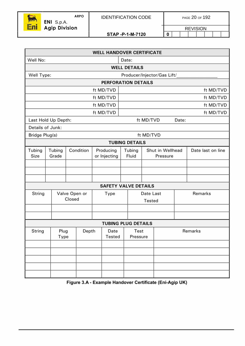
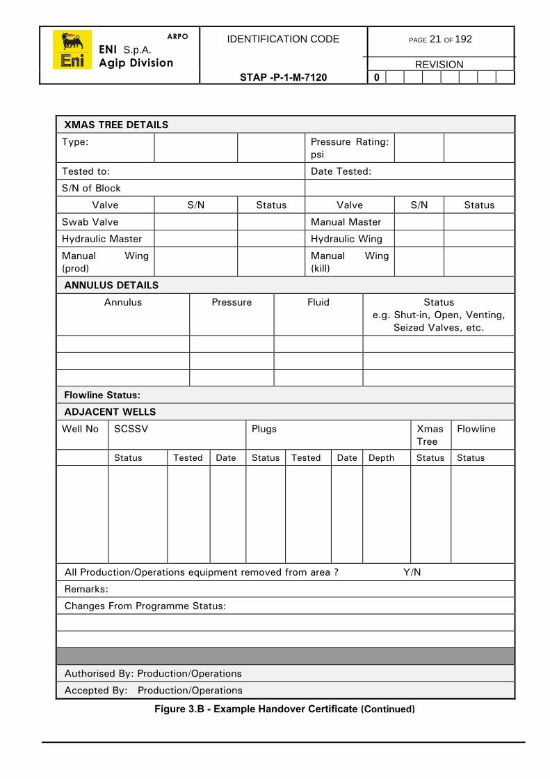
The action of transferring the responsibility for a well between area authority will bedocumented and recorded on the ‘Well Handover Certificate’ or ‘Well Intervention HandoverCertificate’. All preparatory work and the status of the well when handed over will bedescribed in the appropriate Handover Certificate. A typical example of a HandoverCertificate (Eni-Agip) with the information to be recorded is shown in figure 3.a and figure3.b.
The completed Handover Certificate must be signed by the responsible persons handingover and receiving the well. It must be placed in the appropriate well file. Copies are to befaxed to the Well Operations Superintendent when a new well is handed over.
There are two types of Well Handover Certificates:
• Well Handover Certificate• Well Intervention Handover Certificate.
3.6.1. Well Handover Certificate
The well Handover Certificate is to be used for all new wells and wells worked over (Drilling,Completion through to Production).
New Wells
Following the successful drilling and completion of a new well, the Operations departmentwill complete a Well Handover Certificate. Prior to handover of the well to Production, thewell status should be outlined as below:
• Xmas tree installed and fully pressure tested• Swab cap installed and pressure tested• SCSSV installed and fully tested• All wireline plugs removed• All obstructions removed, the wellhead and Xmas tree areas are clean and tidy• Written procedure for the venting of annular pressure, if necessary.
Once the Production Supervisor is satisfied that the status of the well is satisfactory, he willsign the handover certificate in acceptance of the well. Examples of Well HandoverCertificates are shown in figure 3.a and figure 3.b.
ARPO
ENI S.p.A.Agip Division
IDENTIFICATION CODE PAGE 18 OF 192
REVISIONSTAP -P-1-M-7120 0
Workover Wells
Workover is defined in this instance as any well operation which involves the change-out ofany completion component from the wireline re-entry guide to the Xmas tree.
Following the successful completion of a well which has been worked over, Well Operationsdepartment will complete a Well Handover Certificate. Prior to handover of the well toProduction the well status should be outlined as below:
• Xmas tree installed and fully pressure tested• Swab cap installed and pressure tested• SCSSV installed and fully tested• All wireline plugs removed• All obstructions removed, the wellhead and Xmas tree areas are clean and tidy• Written procedure for the venting of annular pressure, if necessary
Once the Production Supervisor is satisfied that the status of the well is satisfactory, he willsign the handover certificate in acceptance of the well.
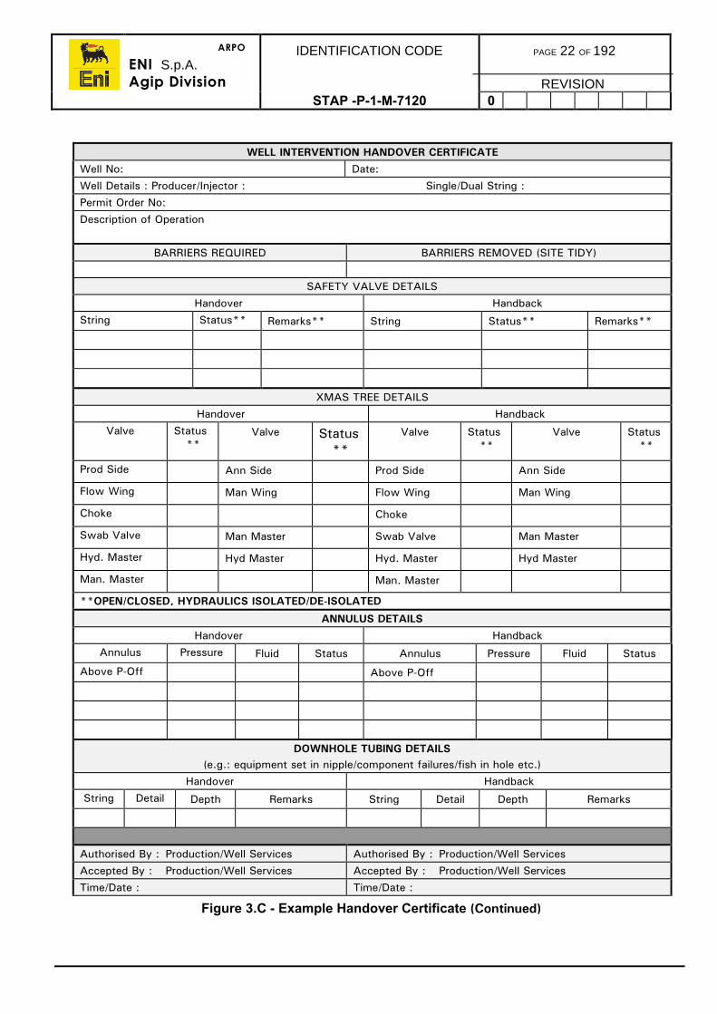
3.6.2. Well Intervention Handover Certificate
The Well Intervention Handover Certificate is to be used for all interventions such as:
• Mechanical wireline operations• Electric wireline operations• Coiled tubing operations• Snubbing operations (except where these constitute a ‘Workover’)• Well stimulation operations.
Prior to handover of the well by Production to Well Services the Production Supervisor willcomplete a Well Intervention Handover Certificate and ensure the following procedures arecompleted:
1) All chemical injection lines on the flowline will be bled down and isolated.
2) The test and production, or injection, header isolating valves will be closed, and theflowline bled down to the closed drains and isolated when no liquid or gas is observedat the sample point. Blind flanges should be installed on the flowline termination.
3) The SCSSV control lines will be bled off ready to be disconnected. All lines from thewellhead to the remote control panel will also be bled down.
4) If the tree is to be removed all instrumentation and control lines will be removed fromthe well.
5) All obstructions (e.g. scaffolding) all instrumentation and control lines will be removed.
Once the Well Operations Supervisor is satisfied that the status of the well is satisfactory hewill sign the Well Intervention Handover Certificate in acceptance of the well.
ARPO
ENI S.p.A.Agip Division
IDENTIFICATION CODE PAGE 19 OF 192
REVISIONSTAP -P-1-M-7120 0
Following an intervention operation the Well Operations Supervisor will complete a WellHandover Certificate. Prior to handover of the well to Production, the well status should beoutlined as below:
• Xmas tree installed and fully pressure tested.• Swab cap installed and pressure tested.• SCSSV installed and fully tested.• All wireline plugs removed.• All obstructions removed, the wellhead and Xmas tree areas are clean and tidy• Written procedure for the venting of annular pressure, if necessary.
Once the Production Supervisor is satisfied that the status of the well is satisfactory, he willsign the Well Intervention Handover Certificate in acceptance of the well. An example of aWell Intervention Handover Certificate is shown in figure 3.c.
ARPO
ENI S.p.A.Agip Division
IDENTIFICATION CODE PAGE 20 OF 192
REVISIONSTAP -P-1-M-7120 0
WELL HANDOVER CERTIFICATE
Well No: Date:
WELL DETAILS
Well Type: Producer/Injector/Gas Lift/__________________
PERFORATION DETAILS
ft MD/TVD ft MD/TVD
ft MD/TVD ft MD/TVD
ft MD/TVD ft MD/TVD
ft MD/TVD ft MD/TVD
Last Hold Up Depth: ft MD/TVD Date:
Details of Junk:
Bridge Plug(s) ft MD/TVD
TUBING DETAILS
TubingSize
TubingGrade
Condition Producingor Injecting
TubingFluid
Shut in WellheadPressure
Date last on line
SAFETY VALVE DETAILS
String Valve Open orClosed
Type Date Last
Tested
Remarks
TUBING PLUG DETAILS
String PlugType
Depth DateTested
TestPressure
Remarks
Figure 3.A - Example Handover Certificate (Eni-Agip UK)
ARPO
ENI S.p.A.Agip Division
IDENTIFICATION CODE PAGE 21 OF 192
REVISIONSTAP -P-1-M-7120 0
XMAS TREE DETAILS
Type: Pressure Rating:psi
Tested to: Date Tested:
S/N of Block
Valve S/N Status Valve S/N Status
Swab Valve Manual Master
Hydraulic Master Hydraulic Wing
Manual Wing(prod)
Manual Wing(kill)
ANNULUS DETAILS
Annulus Pressure Fluid Statuse.g. Shut-in, Open, Venting,
Seized Valves, etc.
Flowline Status:
ADJACENT WELLS
Well No SCSSV Plugs XmasTree
Flowline
Status Tested Date Status Tested Date Depth Status Status
All Production/Operations equipment removed from area ? Y/N
Remarks:
Changes From Programme Status:
Authorised By: Production/Operations
Accepted By: Production/Operations
Figure 3.B - Example Handover Certificate (Continued)
ARPO
ENI S.p.A.Agip Division
IDENTIFICATION CODE PAGE 22 OF 192
REVISIONSTAP -P-1-M-7120 0
WELL INTERVENTION HANDOVER CERTIFICATEWell No: Date:Well Details : Producer/Injector : Single/Dual String :Permit Order No:Description of Operation
BARRIERS REQUIRED BARRIERS REMOVED (SITE TIDY)
SAFETY VALVE DETAILSHandover Handback
String Status** Remarks** String Status** Remarks**
XMAS TREE DETAILSHandover Handback
Valve Status**
Valve Status**
Valve Status**
Valve Status**
Prod Side Ann Side Prod Side Ann Side
Flow Wing Man Wing Flow Wing Man Wing
Choke Choke
Swab Valve Man Master Swab Valve Man Master
Hyd. Master Hyd Master Hyd. Master Hyd Master
Man. Master Man. Master
**OPEN/CLOSED, HYDRAULICS ISOLATED/DE-ISOLATED
ANNULUS DETAILSHandover Handback
Annulus Pressure Fluid Status Annulus Pressure Fluid Status
Above P-Off Above P-Off
DOWNHOLE TUBING DETAILS(e.g.: equipment set in nipple/component failures/fish in hole etc.)
Handover HandbackString Detail Depth Remarks String Detail Depth Remarks
Authorised By : Production/Well Services Authorised By : Production/Well ServicesAccepted By : Production/Well Services Accepted By : Production/Well ServicesTime/Date : Time/Date :
Figure 3.C - Example Handover Certificate (Continued)
ARPO
ENI S.p.A.Agip Division
IDENTIFICATION CODE PAGE 23 OF 192
REVISIONSTAP-P-1-7120 0
4. HOLE PREPARATIONS
The procedures in this section described the preparation of the hole and surface facilitiesfor completion operations.
4.1. PRELIMINARY CHECKS
Sometime prior to completions operations, the following equipment should be checked toconfirm availability and to specification for the forthcoming operations:
a) Workstring of the appropriate grade and size in sufficient length, taking intoconsideration if a tapered string is to be used.
b) BOPs are equipped with the correct size-pipe/variable (single or dual) rams tocover all the range of tubulars to be run in the hole.
c) Wear bushing for the tubing hanger spool, equipped with the running/pullingtool.
d) BOP test tool with the appropriate running and pulling tools and a sufficientquantity of seals.
e) All relevant handling tools for the workstring including elevators and slipsverifying they are in good working condition.
f) Safety valves have been tested and are available already made up with thecrossovers to the workstring and Weco connections to suit the kill lineconnection.
g) The rig has been equipped with the safety and emergency systems as per thecontract and that they are fully operational.
h) Rig pumps are equipped with the appropriate liner sizes and that they havebeen tested.
i) Mud logging or monitoring system is installed and operational.
4.2. WELL CLEAN UP PROCEDURES
After the production casing, or liner, has been cemented in place, a bit and scraperassembly will be run. The purpose of this trip is to clean out any excess cement within thecasing, and particularly to remove any cement that may be on the casing wall at the packersetting depth.
A suitably sized bit, or junk mill, and tandem scraper assembly will be run to clean out thecasing or liner of any excess cement, and to scrape the intended perforated interval(s). Thepacker setting depth will also be scraped during this operation to ensure it will have a goodsetting area. Precise details of packer setting depths, perforation intervals and maximumclean out depth will be given in the well operations/drilling programme.
Note: The casing and liner string may be pressure tested at this point, and aninflow test on liner laps and shoe tracks performed.
For detailed procedures on how to perform inflow and pressure tests refer to the DrillingProcedures Manual.
If a liner lap is a found to be leaking it may be necessary to run a tie back packer into thetop of the liner lap, otherwise it will be necessary to perform a remedial cement squeeze.The decision on which method to adopt will depend on the location and nature of the leak.
ARPO
ENI S.p.A.Agip Division
IDENTIFICATION CODE PAGE 24 OF 192
REVISIONSTAP -P-1-M-7120 0
4.3. BOP STACK CONFIGURATION AND TESTING
a) The BOP stack configuration including ram sizes should be in accordance withthe Well Programme.
b) All components must be fully certified and will be tested with water inaccordance to company policy or local regulations, whichever is the moststringent. testing on a new completion will be accomplished by using either thetest tool or the tubing hanger with the tubing hanger plug installed.
c) Duration of pressure tests will be 10min with a maximum allowable pressuredrop of 100psi unless local legislation dictates otherwise.
d) If it is necessary to use a cup tester for testing the BOP stack, the test pressuremust not exceed the safe working pressure of the casing.
e) The test schedule will be according to local regulations but will be at least every14 days. If operational constraints prevent a scheduled pressure test, adispensation will be requested and issued by the authorities and held on file.
f) The function and pressure tests will be recorded on a chart recorder and thecharts held in file.
g) In workover operations prior to pulling the tubing, the BOP stack will be testedagainst plugs set in the tubing hanger.
h) Function test at the same time as the BOP stack the surface control panel,accumulator package and remote control panel. if using a subsea BOP stack,check from both blue and yellow pods.
4.4. WELL CONTROL
Well control procedures will be in accordance with the Company Well Control PolicyManual, a copy of which must be kept available on the rig.
4.5. OIL BASED MUD DISPLACEMENT
Prior to displacing the well to the completion brine, it will be necessary to displace thedrilling mud from the well. In order to ensure that circulation time, rig time and filtration timeare kept to an absolute minimum, it is essential that the well clean up is as efficient (andeconomical) as possible in removing the mud, solids and any other associated debris in thewell.
4.5.1. Displacement Objectives
• Displace oil based mud out of the well with a minimal interface between the oilbased mud and the clean up chemicals.
• Keep the brine interface to an absolute minimum.• Minimise filtration time and cost.• Change the wetability of all downhole surfaces from oil wet to water wet.• Prevent the discharge of oil based mud, contaminated water and/or
contaminated brine to the environment.• Minimise the requirement for back-loading oily water for disposal.• Remove pipe scale, solids, mud solids and other contaminants from the
wellbore.
ARPO
ENI S.p.A.Agip Division
IDENTIFICATION CODE PAGE 25 OF 192
REVISIONSTAP -P-1-M-7120 0
4.5.2. Logistical Considerations
In advance of the displacement, the logistics of the operation from start to finish should beaddressed. The areas which should be addressed include (but are not limited to) thefollowing:
a) Vessel(s) for back-loading mud and taking on the clean up chemicals, brine andkill pill material.
b) The quantities of clean up chemicals, brine and kill pill material requiredincluding any contingency material that may be required.
c) Pit space requirements for mud and brine and the permits required for cleaningthe appropriate pits and lines.
d) The equipment required to install and operate the filtration equipment.
e) Personnel requirements and available accommodation.
4.5.3. Drilling Fluid Preparation
1) Pick up the workstring with scrapers placed in it to ensure that the liner or casingpacker setting depths are thoroughly scraped during the trip. Once on bottom,bottoms up should be circulated to remove any additional debris.
2) Circulate and condition the oil based mud with oil mud thinner or oil wetting agent inorder that the yield point and gel strengths are reduced but not to a point where thefluid loses the ability to keep barite/drilled solids in suspension. Typically, the yieldpoint should be reduced to 12 lbs/100 ft2 and the 10min gel to <15 lbs/100 ft2. Theactual quantity of material required to do this must be determined by pilot testingperformed by the mud engineer to determine the most cost effective treatment.
3) Throughout the drilling fluid conditioning process, the flow rate used should be themaximum practical rate. At a very minimum, the circulation rate should be just withinthe turbulent flow regime.
4) Whilst conditioning the mud, the drill string should be reciprocated and rotated. Thecombined effect of the scrapers being run in the hole, the high flow rate and thereciprocation/rotation will help to remove/disperse large quantities of mud solids andgeneral debris. The reciprocation stroke should be +/-30ft and the rotation speedshould be +/-15rpm.
5) Near the end of the conditioning operation, temporarily shut down the pumps andstroke each set of pipe rams to clear any debris from the ram cavities except any piperams which are smaller than the workstring. Continue circulation to remove the debris.
6) During this operation, as much of the surface volume of mud should be removed fromthe pits to accommodate the completion fluid and the well clean up chemicals. Oncethe mud has been back-loaded, surface preparation can be carried out.
ARPO
ENI S.p.A.Agip Division
IDENTIFICATION CODE PAGE 26 OF 192
REVISIONSTAP -P-1-M-7120 0
4.5.4. Surface Equipment Preparation
As much of the surface volume of mud should be sent back to the base leaving only onetank into which the mud returned from the displacement can be dumped:
1) Wash and scrub all of the pits and storage tanks designated for the completion fluidwith steam cleaners. Once the top and sides are scrubbed, the bottom of each tankshould be swept to the suction line and the contents sent to a contaminated fluidstorage pit.
2) All pits, sandtraps, gumbo traps, flowlines, ditches and in particular areas where theaccumulation of solids can be overlooked such as underneath lines and grates, aboveand behind angle irons, in the corners and crevices of beams should all be thoroughlycleaned.
3) Once everything has thoroughly been cleaned, fill one pit with fresh water and add therecommended volume of surfactant/flocculant. Agitate the pit to keep the productdispersed.
4) Circulate the surfactant/flocculant pill at the maximum possible flow rate (for +/-20mins) throughout the entire surface system including all pits, pumps, lines or otherareas that the completion fluid may contact.
5) Provided the water is not contaminated it can be dumped. If the water iscontaminated, it should be diverted to a pit designated for contaminated fluid.
6) As before, the pits should all be swept clean and dry.
7) Once all of the above has been done, dump valve seats should be inspected andreplaced wherever necessary and then guided into place to ensure they seal properlybefore filling with brine.
8) Once sealed, all dump valves should be locked shut.
4.5.5. Well Clean Up Pill Sequence
The following is the normal sequence for pumping the various fluids and pills.
a) Weighted hard surface detergent pill
b) Viscous hard surface detergent pill
c) Drill water or seawater
d) Solvent pill
e) Drill water or seawater.
f) Surfactant/flocculant pill
g) Viscous hard surface detergent pill
h) Drill water or seawater (water should be pumped until returns are below 60 NTU,usually 1-2 circulations).
i) Viscous pill.
j) Filtered completion brine
ARPO
ENI S.p.A.Agip Division
IDENTIFICATION CODE PAGE 27 OF 192
REVISIONSTAP -P-1-M-7120 0
4.5.6. Pill Functions
a) The weighted detergent pill is pumped directly behind oil based mud to initiateoil and filter cake removal.
b) The solvent pill has a solvating action on oil based mud residue and filter cakeresidue. This is the main pill for actually removing the mud residue. It should notbe mixed with any water or base oil to cut it back as this reduces the efficiencyof the pill.
c) The surfactant/flocculant pill is used as a chemical flocculating agent to dislodgeany residue loosened by the solvent. A large pill is required to ensure adequatecontact time to remove all solids.
d) The viscous detergent pill is a detergent pill used to convert the surfaces into awater wet state.
4.5.7. Pit Requirements
Pits/storage tanks will be required for the following:
a) Mud pit for the detergent pill
b) Mud pit for the surfactant/flocculant pill
c) The solvent pill in the cement unit
d) Drill water or seawater
e) The viscous pill in the pill tank
f) Completion brine.
4.5.8. Pumping Sequence
The pumping sequence and direction should be in accordance with the well programme.The Mud Engineer should confirm the depths, volumes and rates provide the correctcontact times for the various pills.
Seawater should be pumped until returns are clear (1-2 circulations) after which time theseawater can be displaced out with a viscous pill by the completion brine.
The viscous pill ahead of the brine should be built using the brine as the base.
ARPO
ENI S.p.A.Agip Division
IDENTIFICATION CODE PAGE 28 OF 192
REVISIONSTAP -P-1-M-7120 0
4.6. DISPLACEMENT OF WATER BASED MUDS
The displacement of a water based to a clear fluid is an easier procedure requiring fewersteps. This is due mainly to both fluids being compatible and all surfaces already water wet.
As with the clean up of oil based mud, it is essential that the well clean up is as efficient(and economical) as possible.
As before the logistical aspect of the displacement from start to finish should be addressed.The areas to be addressed include:
1) Transportation for taking well clean up chemicals, brine and filtration equipment/consumables to the rig.
2) Personnel requirements.
3) Surface equipment cleaning.
4.6.1. Drilling Fluid Preparation
1) The mud properties should be reduced to the levels specified for oil based mud,namely YP of 12 lbs/100 ft2 and 10min gel <15 lbs/100 ft2. The most cost effectivemethod of treatment is by adding water to the system. However, this should only bedone under the direction of the Mud Engineer and only after pilot testing.
2) As per section 4.5.3.
3) As per section 4.5.3.
4) The surface volume of water based mud can be dumped overboard (providing theconstituents allow) as can the mud returns from the displacement.
4.6.2. Surface Equipment Preparation
Same as section 4.5.4.
4.6.3. Well Clean Up Pill Sequence
The following is the normal sequence for pumping the various fluids and pills.
a) Drill water/caustic pill.
b) Surfactant/flocculant pill.
c) Viscous detergent pill (un-weighted).
d) Water, pump until returns are below 60 NTU (usually 1-2 circulations).
e) Viscous pill, using the completion brine as the base fluid.
f) Filtered completion brine.
ARPO
ENI S.p.A.Agip Division
IDENTIFICATION CODE PAGE 29 OF 192
REVISIONSTAP -P-1-M-7120 0
4.6.4. Pill Functions
a) Drill water/caustic soda pill is used as a preflush to strip away and denature theheavy, concentrated water based mud filter cake and solids.
b) Surfactant/flocculant pill is used as a chemical flocculating agent to remove theresidues dislodges by the drill water/caustic soda pill. A large pill is required toensure an adequate contact time to remove all solids.
c) Detergent pill is a polishing pill to ensure all downhole surfaces are thoroughlycleaned prior to pumping the seawater.
4.6.5. Pit Requirements
a) Mud pit for the Caustic Soda Pill.
b) Mud pit for the surfactant/flocculant pill.
c) Pill tank for the detergent pill.
d) Drill water or seawater as required.
e) Pill tank for the viscous pill.
f) Completion Brine.
4.6.6. Pumping Sequence
The pumping sequence and direction should be in accordance with the well programme.The Mud Engineer should confirm the depths, volumes and rates provide the correctcontact times for the various pills.
4.7. COMPLETION AND WORKOVER FLUIDS
4.7.1. Brines Transportation
Prior to loading any brine at the suppliers facility the vessel tanks and manifolds will beinspected for cleanliness and dryness.
Note: Boat manifolds may contain residual materials that could contaminate thebrine. Therefore all manifolds, pumps, etc. that will be involved in brinedelivery will be thoroughly flushed and dried.
Brine will not be loaded onto a vessel or truck until the Company’s responsible person issatisfied that the brine will arrive at the rig site with the same clarity, density, and solidscontent as originally loaded.
Samples of the brine will be taken during the loading operation from the loading tanks andthe vessel's receiving tanks or truck. The volume, density and clarity of the fluid afterloading must be identical to the fluid from the suppliers tanks.
Prior to transferring the brine to the installation from the tanks all hoses, connections, dumpvalves, etc. will be checked for leaks.
The volume and density of the brine will be monitored as it is transferred from the vessel.Any discrepancies in density and volume will be recorded.
ARPO
ENI S.p.A.Agip Division
IDENTIFICATION CODE PAGE 30 OF 192
REVISIONSTAP -P-1-M-7120 0
4.7.2. Completion And Workover Fluid Quality
The quality of the fluid used during a completion and workover operation cannot be over-emphasised as the productivity is governed not only by the damage caused by visiblecontaminants such as solids but also the damage caused by invisible contaminants such ascalcium ions, sulphate ions and dissolved iron. It is, therefore, essential that all of these andother similar contaminants are controlled to as low a level as feasible and, whereverpossible, completely removed (Refer to the Drilling Fluids Manual).
Other contaminants such as iron and sulphates can be controlled on surface by chemicaltreatment but can be avoided altogether by ensuring that the quality of the fluid supplied iscorrect, the quality of all the sacked and drummed material meets the required specificationand the rig is thoroughly cleaned before taking on the completion brine.
During well completion and workover operations, all steps must be taken to ensure that, ifany fluid is in contact with the formation, it is both clean and filtered. A fluid in any othercondition will, for the reasons stated above, result in some degree of formation impairment.
4.8. FILTRATION SYSTEMS
The prime filtration system is the Diatomaceous Earth filter press with a bag filter system foruse as a downstream guard filter. Sometimes, on standby is a low pressure, Cartridge Filterunit.
Both the DE and the cartridge units are capable of filtering down to 2 microns.
The DE is preferable as the prime equipment as it is more suited to high solids loadingwhich can be removed using various different grades of DE to form a porous, permeablefilter cake on a filter cloth. The nature of the DE is such that it must be added using a ‘safehandling system’ to ensure that there is a totally dust free environment thereby eliminatingany hazard to the operator or any other personnel in the vicinity. On no account shouldloose DE be used.
4.8.1. Fluid Cleanliness
Before filtering, all the tanks should be thoroughly cleaned out and any mud residueswashed out (as per the pit cleaning procedure described earlier in section 4.5.4).
a) A pit of brine will not be filtered by circulation on itself.
b) Brine will be filtered from the dirty pits to a clean empty tank.
c) All filtered brine will be checked to ensure that it meets the required level ofcleanliness. Normal specifications are:
• By laser particle counter: < 250ppm total undissolved solids• By turbidity meter: < 20NTU• By centrifuge: < 0.01% by volume solids.
ARPO
ENI S.p.A.Agip Division
IDENTIFICATION CODE PAGE 31 OF 192
REVISIONSTAP -P-1-M-7120 0
4.9. LOST CIRCULATION
The use of lost circulation materials may be necessary if the well has suffers any seriousfluid losses as can be experienced such as on open hole, gravel pack or wells which areperforated prior to running the completion, etc.
The types of LCM pills preferred for the various uses from slow seepage to high losses inparticular situations are fully described in the Drilling Fluids Manual along with theformulations and placement procedures.
Prior to using an LCM pill, consideration will be given to reducing the hydrostatic head byreducing the brine weight (with drill water) and so reduce the level of losses. This will onlybe attempted if the reduction in weight does not compromise the safety of the well.
Obviously the LCM pills used in completion operations should be selected in order minimisepotential damage to producing formations. Some of the most common LCM pills used incompletion operations are described below.
4.9.1. Viscous Pills
These can be built, either, using drill water, completion brine or a higher weight brine as abase and adding a predispersed liquid viscosifier to increase the funnel viscosity accordingto the well programme. The addition of a predispersed liquid viscosifier is preferable as itwill yield rapidly without forming ‘fish eyes’ which may cause a problem when it comes timefor the removal of the pill downhole.
There are both advantages and disadvantages is using high viscosity pills for controllingfluid loss. These are as follows:
1) Advantages
• They contain no particulate material to impair the formation.• They can be built quickly and easily.• They can be removed by thermal degradation, acid, chemical breakers or by
flowing the well.
2) Disadvantages
• They are limited normally to temperatures <280 F.• They are only effective in low permeability formations where seepage losses are
low to moderate (<1.5 - 2bbl/min).
4.9.2. Sized Salt Pills
The actual composition of the sized salt pill will be determined primarily by the porosity,permeability and temperature of the formation to be bridged.
Sized salt pills must be formulated in a saturated brine base to prevent solution of thebridging material.
A typical formulation for a sized salt pill in a 10ppg sodium chloride brine is as follows:
Volume per bbl - Vol. as requiredFormulation Saturated Brine 0.94bbl
Bridgesal Plus 500lbs
ARPO
ENI S.p.A.Agip Division
IDENTIFICATION CODE PAGE 32 OF 192
REVISIONSTAP -P-1-M-7120 0
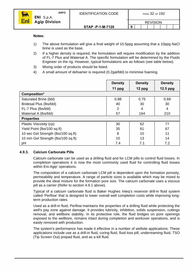
Notes:
1) The above formulation will give a final weight of 10.5ppg assuming that a 10ppg NaClbrine is used as the base.
2) If a higher density is required, the formulation will require modification by the additionof FL-7 Plus and Watersal A. The specific formulation will be determined by the FluidsEngineer on the rig. However, typical formulations are as follows (see table below).
3) Mixing order of products should be listed.
4) A small amount of defoamer is required (0.2gal/bbl) to minimise foaming.
Density
11 ppg
Density
12 ppg
Density
12.5 ppg
Composition*Saturated Brine (bbl)Bridesal Plus (lbs/bbl)FL-7 Plus (lbs/bbl)Watersal A (lbs/bbl)
0.88402
57
0.75304
164
0.69304
210
Properties
Plastic Viscosity (cp)Yield Point (lbs/100 sq.ft)10 sec Gel Strength (lbs/100 sq.ft)10 min Gel Strength (lbs/100 sq.ft)pH
30358
107.4
626110137.1
776711147.2
4.9.3. Calcium Carbonate Pills
Calcium carbonate can be used as a drilling fluid and for LCM pills to control fluid losses. Incompletion operations it is now the most commonly used fluid for controlling fluid losseswithin Eni-Agip’ operations.
The composition of a calcium carbonate LCM pill is dependent upon the formation porosity,permeability and temperature. A range of particle sizes is available which may be mixed toprovide the ideal mixture for the formation pore size. The calcium carbonate uses a viscouspill as a carrier (Refer to section 4.9.1 above).
Typical of a calcium carbonate fluid is Baker Hughes Inteq’s reservoir drill-in fluid systemcalled ‘Perflow’ that is designed to lower overall well completion costs while improving long-term production rates.
Used as a drill-in fluid, Perflow maintains the properties of a drilling fluid while protecting thewell's pay zone against damage. It provides lubricity, inhibition, solids suspension, cuttingsremoval, and wellbore stability. In its protective role, the fluid bridges on pore openingsexposed to the wellbore, remains intact during completion and workover operations, and iseasily removed with production.
The system's performance has made it effective in a number of wellsite applications. Theseapplications include use as a drill-in fluid, coring fluid, fluid loss pill, underreaming fluid, TSO(Tip Screen Out) prepad fluid, and as a kill fluid.
ARPO
ENI S.p.A.Agip Division
IDENTIFICATION CODE PAGE 33 OF 192
REVISIONSTAP -P-1-M-7120 0
The system's simplified cleanup reduces rig time during completion and workoveroperations. While other fluids require costly processes for removal, removal is simplyaccomplished by flowing the well.
The system utilises very pure calcium carbonate with a broad particle size distribution toeffectively bridge the pore openings of the formation. The bridging agent and polymerchemistry form a thin filter cake to protect the pay zone from damage caused by fluidinvasion. The filter cake is effectively removed by low break-out pressures, leaving nosignificant residual material to inhibit the well's production.
Before using a calcium carbonate pill, any potential damaging effects from the calciumcarbonate needs to be assessed as any particles trapped in pore spaces can only beremoved by an HCl acid treatment.
4.10. CASING GAUGE CONTROL
Prior to running any completion equipment, it is necessary to ensure the hole is withingauge to allow passage of tools such as packers and TCP guns.
Checking the hole gauge is carried out by electric line services by running a gauge ring of asize according to the casing drift size. It is normal practice to run the gauge ring inconjunction with a junk basket after the well clean out procedure. The junk basket is run tocatch junk which has not been circulated out of the hole during the well clean out operation(typically rubber, pieces of cement, etc.).
Any tight spots should be logged and reported. Ultimately the casing may require furtherscraping. It is extremely important that the casing is drifted as the sticking of completionequipment can incur high costs in retrieval, loss or damage to equipment and may evencause a side-track.
ARPO
ENI S.p.A.Agip Division
IDENTIFICATION CODE PAGE 34 OF 192
REVISIONSTAP-P-1-7120 0
5. PERFORATING PROCEDURES
5.1. GENERAL
Two methods are currently used to perforate wells: wireline conveyed guns and tubingconveyed guns (Refer to the Completion Design Manual). In the drive to obtain maximumperforating efficiency, tubing conveyed perforating is the preferred method for mostcompletion operations as the zones to be tested can be perforated underbalanced in onerun with a large size charges, if possible. However, under some circumstances wirelineconveyed guns may still be preferred. The procedures for both methods are described inthe following sections.
The type of explosive to be used will depend mainly on the bottom hole temperature andthe length of time the guns are likely to be on bottom before firing. Refer again to theperforating section in the Completions Design Manual and to suppliers technicalspecification sheets.
The BOPs and the rig manifolds should have undergone a recent full programme ofpressure testing.
At the safety meeting, the perforating operation should be discussed in fine detail. Apartfrom outlining the sequence of operations and contingency plans, all present should beclearly aware of the extent to which their own area of responsibilities may affect, and beaffected by, the special requirements of a perforating operation.
The perforating engineer should have a diagram of the well, clearly indicating the interval(s)to be perforated, the fluids present, the pressures/temperatures expected and the depths,diameters and angles of any changes in the well geometry. There must be no doubt aboutthe method of referencing the top shot and the settings of the tools (e.g. shear pin settings,timer delays, etc.). These must be discussed with the Completions Supervisor and fullyunderstood.
No crane lifts should be made over loaded perforating guns or over the logging cable.
Only essential personnel will be permitted in the vicinity of loaded guns, especially at theloading area, catwalk, drill floor and spider deck. All personnel, except the perforatingengineer, should be clear of these areas while the guns are being armed.
Diving activities are not permitted during the perforating operation.
Electrical Activation
In addition, whenever the gun firing sequence is initiated by electrically operated detonators, thefollowing will apply:
• Weather forecasts (two independent sources) must confirm there will be nolikelihood of electrical storms for the duration of the perforating operation.
• Offshore, the perforating engineer should remain on the drill floor at all timeswhen TCP guns are in the hole still above ground level.
• The perforating engineer must verify there are no stray voltages (greater than0.25 V) between the rig and the casing or riser.
• Radio silence must be in force before connecting the firing head and until theguns are 100m below ground level, unless the Schlumberger SAFE firingsystem or similar is used (Refer to section 2)).
ARPO
ENI S.p.A.Agip Division
IDENTIFICATION CODE PAGE 35 OF 192
REVISIONSTAP -P-1-M-7120 0
• The firing head detonator must not be installed until the Completion Supervisorconfirms to the Perforating Engineer that the rig is on radio silence.
• On recovery of the guns, regardless of any indications that the guns have fired,radio silence must be reinstated prior to the guns being retrieved above 100metres below the sea bed. This period will end only after the detonator sub-system has been removed and the perforating engineer has confirmed to theCompletion Supervisor that the guns have been made safe.
• No electric/MIG welding is permitted during the perforating operation.
• Cathodic protection should be shut down and isolated during the period ofradio silence.
• No diving is to be allowed during perforating.
• No crane lifts should be made over the wire during perforating, if applicable.
• No boats should be alongside during perforating.
• No helicopter landings should be allowed during radio silence.
• All non-essential personnel should be excluded from the areas affected,including the gun loading area, the catwalk, the drill floor and the moonpool,around the riser below the drill floor.
5.2. METHODS OF PERFORATING
The perforating procedure is dependent upon the type of gun system used for theapplication in the completion process. The six main methods are:
• Wireline-conveyed carrier guns inside casing - perforating overbalance• Wireline-conveyed through tubing guns - perforating underbalance• TCP run on a temporary well test string - perforating underbalance• TCP guns run on the permanent completion string - perforating underbalance• TCP guns run on a perforating anchor - perforating underbalance• TCP guns run on coiled tubing - perforating underbalance
Common to all perforating operations, a safety meeting should be held before theoperation commences. This is important because perforating will impose restrictions onother rig operations, such as radio silence, diving and use of the cranes. These proceduresare to be used as a guideline. They should be used only in conjunction with other companyprocedures for these operations.
5.3. GENERAL SAFETY PROCEDURES
The following comments are applicable to both TCP and wireline conveyed methods.Additional comments are given in section specific to wireline conveyed perforating.
a) All perforating operations, since they involve the handling and use of explosivesand possibly radioactive materials, require special safety procedures to bestrictly observed at all times.
b) Perforating operations should be carried out strictly according to the safetypolicies of Eni-Agip and the perforating Contractor. In the event of anyinconsistency between policies, the most conservative policy will apply.
ARPO
ENI S.p.A.Agip Division
IDENTIFICATION CODE PAGE 36 OF 192
REVISIONSTAP -P-1-M-7120 0
a) Operations involving the use of explosives shall only be performed byContractor’s specialised personnel responsible for perforation and similaroperations. The number of persons involved shall be as low as possible.
b) Only perforating Contractor’s personnel are allowed to remain in the hazardousarea (gangway, rig floor etc.) during arming of guns. The number of personnelshould be limited when the guns are within 500ft of surface when tripping in andout of the hole.
c) Any operation involving the use of explosives is not allowed in the presence ofthunder, lighting and thick fog, as these are sources of electric potential.
d) Explosives shall be kept on site for the shortest possible time, any remaining atthe end of the operation shall be removed from the installation.
e) Explosives shall be stored on site in proper containers, within a confined area onthe rig. Detonators shall be stored in separate boxes, in the same area asexplosives.
f) Warning signs must be placed around the hazardous area where explosives areused.
g) All radio transmitters, radio beacons included, within a radius of 500ft from thewell, shall be turned off, (since they may detonate blasting caps), starting fromgun arming until perforating guns are 500ft below the sea bottom (similarly,when pulling guns out of hole and guns above 500 ft). All portable transmitters(both Eni-Agip’s and Contractors) shall be placed inside the Eni-Agip office andturned off to avoid accidental transmission. Avoid critical periods of perforatingcoinciding with arrival and take-off of helicopters.
h) Cranes and welding machines shall be put out of service starting from gunarming till gun pulling out and unloading.
i) District Office shall be advised by the Well Operations Supervisor on theestimated time of radio silence two hours before starting operations. The RadioOperator shall communicate actual timing.
j) Casing perforating can be performed during daylight or at night. However, thefirst series of shots must be carried out in daylight hours. Before perforatingcasing, the acceptable cement job quality shall be ascertained by means ofCBL/VDL and/or by squeeze jobs.
k) Explosives are to be transported unarmed and clearly labelled to the site insecure and protective containers. Extreme care must be applied during loadingand off-loading.
l) At the rig it is the responsibility of the Installation Manager to ensure that theseprecautions are taken.
ARPO
ENI S.p.A.Agip Division
IDENTIFICATION CODE PAGE 37 OF 192
REVISIONSTAP -P-1-M-7120 0
5.4. WIRELINE CONVEYED PERFORATING
There are two alternatives to be considered when perforating using wireline conveyed guns:casing guns and through-tubing guns. In both cases depth control is provided by running aGamma Ray/CCL above the gun, and the guns are fired by electrical signal.
Casing Guns
Casing guns are large diameter perforators which cannot be run through normal tubingsizes. Therefore they must be used prior to running the test string and usually inoverbalance conditions (completion brine or drilling mud). A shooting nipple should be usedwhen using this method.
Through-Tubing Guns
Through-tubing guns are small diameter guns run through the test string. They can be usedto perforate underbalanced, and hence eliminate the risk of damaging the formation withwellbore fluids immediately after perforating. Also, and especially in production situations,they can be run and fired with the well ‘nippled up’ and intrinsically safe. The gun size whichcan be run is limited by the tubing size.
5.4.1. Casing Guns Run In Overbalance
1) A safety meeting should be held before perforating. The safety aspects of perforatingwith casing guns are:
• The well must be stable with an overbalance mud• There must be an adequate surface supply of kill fluid• The BOPs should have been recently tested• Radio silence must be in force before connecting the cable head until the guns
are 100 metres below the sea bed.
On recovery of the guns, regardless of any indications that the guns have fired, radiosilence must be in force before the guns are pulled back past 100 metres below groundlevel and until the cable head is removed.
2) The logging engineer should be given a diagram of the well showing the depths of allrestrictions or changes in diameter.
3) Wireline should be rigged up as per the procedure in the Wireline Procedures Manual.
4) If perforating inside casing ensure the length of the gun assembly is less than thedistance between the blind rams and the grease head.
5) The distance between the top shot and the GR/CCL should be measured. It maysometime no be necessary to run a record the depth by GR or CCL if depth can becorrelated to a sump packer or bridge plug.
6) The logging engineer must not connect the cable head until the Well OperationsSupervisor, or his designated representative, has confirmed that radio silence isinstated.
7) There is no restriction on running speed but care must be taken at any restrictions andwhen applying the brake.
ARPO
ENI S.p.A.Agip Division
IDENTIFICATION CODE PAGE 38 OF 192
REVISIONSTAP -P-1-M-7120 0
1) The Logging Engineer must inform the Completion Supervisor, or his designatedrepresentative, when the guns are deeper than 100 metres below ground level.
2) Tie on depth to the CBL/VDL/GR/CCL log. Record a short section of film across theinterval to be perforated showing at least five casing collars and the pup joint at thetop of the reservoir section. The well should be perforated from the bottom upwards.
3) When the gun is on depth and ready to be fired, the logging engineer must inform theWell Operations Supervisor, or his designated representative, and the driller, whoshould observe the well for losses or gains when the gun is fired.
4) Pull out at less than 5,000 ft/hour to avoid swabbing.
5.4.2. Perforating Procedures For Through Tubing Conveyed Guns
This operation will only be done once the cushion has been circulated into place.
Since only the first run can be perforated underbalance, it is common practice to perforate thebest (highest permeability) zone first, otherwise the well should be perforated from the bottomupwards to minimise the chance of picking up debris on the cable.
1) A safety meeting will be held to review procedures and safety, specifically:
• The well is in underbalance and will be live after the first run• The wireline BOPs should have been pressure tested• The surface rig up must be pressure tested before each run• Ensure the GR/CCL log across zone of interest is available.
2) The logging engineer should be given a diagram of the well and test string showingthe depths of all restrictions or changes in diameter and he should check that he hassufficient weights for the maximum anticipated wellhead pressure.
3) Rig up wireline for a full bore drift run. Run in the hole and drift the tubing.
Note: Prior to arming the guns, the Offshore Installation Manager will ensurethat conditions for safe operations exist. He should then inform base,standby vessels, supply boats and any relevant persons that the rig ispassing into radio silence.
4) The wireline should be rigged up with the lubricator system, grease flow tubes,hydraulic stuffing box, tool trap, ball check valve and line wiper. Once radio silencehas been obtained, rig up the perforating guns into the lubricator and pressure test.
5) Monitor the pressure in the ‘A’ annulus.
6) Ensure the surface tree master and swab valves are open and run in the hole with theperforating gun tool string.
7) Correlate the GR/CCL to the original GR log. Record a short section of film across theinterval to be perforated showing at least five casing collars and the pup joint at thetop of the reservoir zone. Do not run down into the perforations on subsequent runs.
8) Position the string at the desired perforating interval and fire the guns.
9) Observe and record WHSIP to confirm the guns have fired.
ARPO
ENI S.p.A.Agip Division
IDENTIFICATION CODE PAGE 39 OF 192
REVISIONSTAP -P-1-M-7120 0
1) Pull out of the hole with the perforating string, taking care when passing throughrestrictions.
2) Repeat steps until the total required interval has been perforated. Do not flow the wellwhile pulling the guns back through the tubing to surface.
2. Stop when the guns are at 100 metres below ground level until the CompletionsSupervisor, or his designated representative, confirms that there is radio silence.
1) The gun should be inspected at surface to check that all charges have detonated.Care should be taken as pressure can be trapped by debris behind the gun ports. Afilm record should be made of the job and the explosion register should be updated.
2) Open the well to flow and continue as per the Completion Programme.
5.5. SAFE SYSTEM
The SAFE system was developed for wireline conveyed perforating systems and will beused unless otherwise authorised.
5.5.1 General
There are two types of detonators in general use today:
a) The Electric Detonator or Blasting Cap (which is classed as an Electro ExplosiveDevice).
b) The Percussion Detonator or Percussion Cap.
Both of these systems contain ‘primary high’ explosives which are initiated by an electriccurrent heating a filament wire in the case of the blasting cap and a direct mechanical shockin the case of percussion cap. The blasting cap can also be initiated by shock as it containsprimary high explosives.
In order to store and handle these detonators, special safety precautions must be taken.These precautions include, in the case of electro explosive devices, the elimination of strayelectric potential differences while arming guns at surface and when returning to surfaceafter perforating.
Stray electric potential differences can originate from:
• RF Radiation• Impressed Current Cathodic Protection• Electric Welding• Electric Generators and Motors• Lighting Storms.
The SAFE system was developed to preclude the loss of radio communication and othervital equipment during perforating operations.
ARPO
ENI S.p.A.Agip Division
IDENTIFICATION CODE PAGE 40 OF 192
REVISIONSTAP -P-1-M-7120 0
5.5.1. SAFE System Description (Slapper Activated Firing Explosives)
The two main components of the SAFE system are the EFI (exploding foil initiator) and theESIC (electronic secondary-explosive cartridge). All the guns are shot from the bottom upwith the exception of the Enerjets and Back-off.
The EFI contains no primary high explosives and so cannot be set off with the application ofheat or mechanical shock.
With the guns on setting depth, DC power( positive or negative) is applied from the surfaceto the ESIC, which steps up the voltage and stores this energy in a capacitor. The capacitoris controlled by a triggering device. When the trigger threshold is reached, the capacitordischarges rapidly into the EFI, thereby initiating the explosion chain.
The SAFE system is based on a series of ‘basic units’. These are manufactured in sizesthat allow a range of guns to be fired from 11/16ins to 7ins. Several guns can be runsimultaneously in the hole and selectivity of shooting these is achieved by connecting anESIC cartridge to each gun.
Advantages:
•• Operates without shutting down radios, electric welding and cathodic protection.• Explosive components contain no primary-high explosive.• Overall operating time reduced.• Operates safely next to radio transmitters and powerlines.
5.6. TCP PROCEDURES
TCP perforating is now the most common method of perforating today as it has manyadvantages over wireline conveyed perforating. These advantages include:
• The guns can be made up and run in the hole on the completion string or on anindependent anchor system.
• The packer is set and the string fully tested and completed before guns are tobe fired.
• The well can be perforated underbalanced to increase the perforating efficiencyfor completion.
• Various methods of detonation can be utilised depending on well conditions.• Long perforation intervals can be fired in a singe run.• Accurate placement and efficient detonation in high deviation wells with
selective zonal perforations can be achieved.• Guns and charge size can be maximised for optimum perforating efficiency.• Guns can be loaded to perforate specific target intervals.
Perforating systems are available which allow several different intervals to be independentlyperforated and tested during one trip in the hole.
Ensure that the casing/liner has been gauged and junk basket/junk sub trip has been madeprior to running the TCP guns.
Note: If the guns are to be dropped into the sump, it is essential that the depthof the rat hole is sufficient to swallow the guns.
ARPO
ENI S.p.A.Agip Division
IDENTIFICATION CODE PAGE 41 OF 192
REVISIONSTAP -P-1-M-7120 0
5.6.1. Well Preparation for TCP Operations
Cleanliness is of prime importance in being able to obtain optimum perforating efficiency.Dirty tubulars and well conditions may lead to serious problems, therefore the followingpoints should be carefully considered.
Clean Casing
This helps prevent problems with packer setting. A bit and scraper run to clean up thecasing and condition the hole is essential, followed by a gauge ring run before TCP guninstallation (Refer to section 4.10). This provides a good clean area for the packer to setand seal off in, hold high differentials and withstand the shock of the gun detonation.
Clean Tubing
This is also a vital factor that assists in a trouble free firing operation. Tubing should alwaysbe rabbited before being run. This prevents any pipe scale, mud cake or general debrisfrom falling down to settle out and create a barrier around and over any firing head orstinger. This is critical if bar drop methods or wireline conveyed firing heads are used.
Any preventative methods employed in the area of scale/dope are strongly recommended.
Clean Fluids
These are important in any perforating operation. By keeping the downhole fluidenvironment as clean as possible, less problems will be encountered later in the operation.As stated above, solids settling out can cause problems/delay/cost, so an emphasis wherepossible on clean, filtered well fluids is essential. Perforation tunnel and near wellboredamage are also a consideration (Refer to the Drilling Fluids Manual for Eni-Agip’srecommended fluids policies, recipes and cost considerations.
BOP Tests
It must be taken into consideration that the perforating/testing and killing procedures maytake a considerable time to conduct, therefore the next scheduled BOP test may berescheduled to take this into account.
5.6.2. Ancillary TCP Equipment
The following is a list of the most common equipment used in conjunction with the gunsections to help installation and firing.
Bullnose
Allows the test string to enter liner tops easily. It may also be ported to allow pressurecommunication with a pressure activated firing head on the bottom of the guns.
ARPO
ENI S.p.A.Agip Division
IDENTIFICATION CODE PAGE 42 OF 192
REVISIONSTAP -P-1-M-7120 0
Circulating Sub
This sub is optionally run above the mechanically activated firing head. It is a ported subwhich allows circulation and beneath the ports is a brass or glass disc preventing debrisfrom dropping onto the mechanical firing head. The drop bar must pierce the disc beforepassing on to the firing head. The ported sub acts as a perforated anchor after the gunshave fired.
Gun Drop Sub
If the perforated zone is to be production logged or stimulated with coil tubing a gun dropsub should be incorporated into the string. This releases the guns, which fall into the sumpfor which sufficient sump must be provided. Gun drop subs can be operated; mechanically,using slickline, hydraulically by pressuring up on a dropped ball, or automatically on gundetonation.
The recommended method is to use slickline as it is less complicated and less liable to fail.With any of the methods, it is prudent to make a conformation check run to ensure the gunshave dropped.
Spacer Tubing
Spacer tubing is inserted between the gun drop sub and the top of the guns. The distancebetween the gun drop sub and the top perforation should be at least 50ft if productionlogging is to be performed.
Shock Absorber
This is an optional tool which may be run to protect downhole equipment from the shock ofgun detonation. This is important when, in particular, downhole gauges are run below thepacker. Both radial and longitudinal force shock absorbers are available.
Radioactive Sub
A radioactive tag in a sub should be installed in the string within the proximity of the packer.This sub is used as a marker when performing the GR/CCL correlation for depth control. Ifthe formation has little GR character, radioactive collars can also be included in the casingstring for definitive depth control. If chrome tubulars are being used consideration must begiven to the non magnetic properties of the pipe with regard to the CCL.
TCP String
If using a test string to conduct a shoot and pull procedure, the full range of stringcomponents such as packer, test tubing, tester valve, circulating valves, etc. need to beemployed as per the Company Well Test Manual.
Shot Detection
Shot detection equipment comprises acoustic detectors (hydrophones), vibration detectors(accelerometers) and the normal surface pressure gauges. Using a combination of the datadetected by these sensors it is usually possible to confirm gun detonation.
ARPO
ENI S.p.A.Agip Division
IDENTIFICATION CODE PAGE 43 OF 192
REVISIONSTAP -P-1-M-7120 0
5.6.3. Firing Systems for TCP Operations
It is normal practice to run the TCP guns with two firing systems, whenever possible, to improvethe chance of a successful operation especially when running the guns on the bottom of acompletion. A common combination is to use a tubing pressure actuated system as the primarymeans of detonating the TCP guns with a mechanical system as the back up. There are fourmain types of firing mechanisms for TCP guns. Only top down firing mechanisms should beused for safety when arming the guns. The operation of each firing mechanism is:
Tubing Pressure Activated
The guns are fired by pressuring up the test string and then bleeding off the pressureimmediately. A time delay device is incorporated to allow time to bleed off. This device canbe either hydraulic or a slow burning fuse. Some of the firing heads for this system arewireline retrievable which gives another back up option. However, this would preclude theuse of the drop bar system as a back up. Although this technique could be expensive onnitrogen, it is well suited to the use of a nitrogen cushion but the time delay on the systemwill have to be increased to allow time for the nitrogen cushion to be bled off.
Mechanical Impact
The TCP guns are detonated by the mechanical impact of a firing bar, which for safety mustbe run on wireline. (This system is colloquially known as the drop bar system.) Since thesystem can be affected by debris in the tubing, the completion fluid must be kept clean. Thesystem is preferred as a back up instead of the primary firing mechanism because of theneed to use wireline.
Electrically Activated
With this system, the guns are fired with an electrically-initiated detonator which must be runon a logging cable. Therefore the pressure control system must be rigged up. Since aninductive or wet electrical connection must be made at the firing head, the system is alsosusceptible to debris. This system is rarely used on well tests as the only is that the firingheads for this system are wireline retrievable, hence the guns can be run unarmed and, inthe case of a misfire, the firing head can be recovered on wireline to determine the cause ofthe misfire.
Retrievable Slickline Firing Head
This type of head was primarily designed to overcome the concerns over about thepossibility of guns being denoted by stray pressure or tools/debris/unnamed articles whichcould fall down through the tubing string and force the detonating pin into the initiator. Withthis type of head, this possible problem has been completely eliminated due to the designof the system.
The guns are run in the hole without the firing head. Then, when ready to arm the guns, thehead is run to depth on slickline and latched on to the firing stem or stinger. This systemprovides its own back-up in that if the firing head does not work, it can be retrieved and areplacement run.
Retrievable firing heads are available with mechanical, hydraulic or electric triggering.
ARPO
ENI S.p.A.Agip Division
IDENTIFICATION CODE PAGE 44 OF 192
REVISIONSTAP -P-1-M-7120 0
5.6.4. General TCP Safety Precautions and Running Procedures
A safety meeting should be held before running the guns. The following safety aspects ofperforating with TCP guns should be discussed:
• The well is underbalance and will be live after firing.• Radio silence must be in force before connecting the firing head until the guns
are 100 metres below ground level. On recovery of the guns, regardless of anyindications that they have past 100m below ground level until the firing head isremoved.
• A 3m spacer should be installed on top of the gun so that it will be armed withthe guns below the rig floor.
• Firing heads must be removed before the guns are pulled back above the drillfloor.
• The guns must include a pressure bleed off so that any trapped pressure can bereleased.
Running procedure
1) The elevators should be changed out to match the special lift sub and the correct slipsfor the gun size must be used together with a dog clamp. The perforating engineer willprovide a list of the correct torque for each component of his equipment.
2) After clearing the area of non-essential personnel, pick up the guns on a tugger withthe special lift sub. The guns are made up just as tubing singles but avoid mechanicalshock because the internal carriers can be displaced.
3) Check the booster positions and 'O' rings before making up guns. The firing headdelay will have previously been set according to the test programme and agreed bythe Perforating Engineer.
4) Before connecting the firing head, clear the drill floor and cellar deck areas of all non-essential personnel.
5) A spacer sub must be installed so that the top shot is well below the rig floor when thegun is armed. Do not pull the gun back above the drill floor once the firing heads areinstalled.
6) Run the rest of the test string but take special care that no debris shall fall down ontop of the firing head. If tubing is in poor condition, ensure it is cleaned and rabbittedto remove all loose rust and scale.
7) The string must be run without jarring to avoid premature detonation because mostfiring heads use shear pins.
8) Run the string to set the guns approximately on depth.
9) Rig up the main logging cable and run a gamma ray logging tool down to thecorrelation depth. Tie on depth to the reference log and record sufficient film to showboth radioactive pip markers and any zones of gamma ray character on the log.
10) The required spacing out should be calculated according to the completion installationprocedures in section 8.5.
11) Set the packer and land the completion string. If there is any doubt about the spaceout, re-run the gamma ray tool to ensure that the guns are set on depth.
ARPO
ENI S.p.A.Agip Division
IDENTIFICATION CODE PAGE 45 OF 192
REVISIONSTAP -P-1-M-7120 0
1) Install the surface equipment (Xmas tree or flowhead) and pressure test as per thewell programme.
2) Circulate the cushion into place and line up the well to flow.
5.6.5. Firing Procedure for Tubing Installed Pressure Activated Head
Complete the steps in section 5.6.4.
1) Start recording wellhead pressure.
2) Pressure up on the tubing with the cement pump, or with the nitrogen unit, if anitrogen cushion is employed.
3) Hold the pressure for one minute. Close the kill wing valve and bleed off pressure viathe choke manifold to provide the desired underbalance.
4) If there are no indications that the guns have fired after a reasonable amount of time,re-pressure up the string in stages to 1,000 psi above the firing pressure, observe forleak off then bleed back to the underbalance.
5) If there are still no signs of gun detonation after a further hour, use the back up firingsystem.
6) Continue with the completion programme.
5.6.6. Firing Procedure for Wireline Installed Pressure Activated Head
The procedure for perforating with a wireline retrievable pressure operated firing head isexactly the same as that in section 5.6.5 except that the head is run into the receptacle afterthe string has been installed and pressure tested.
In the event that there is no indication of firing with this system, the head is simply retrievedfor checking and another head reinstalled.
5.6.7. Firing Procedure for Mechanical Impact Activated Head
Complete the steps in section 5.6.4.
1) Rig up the slickline lubricator.
2) Ensure that there is sufficient weight on the wireline toolstring and inspect/clean thefiring bar impression nose.
3) Pressure test the lubricator, equalise, open the tree valves and run into the hole.
4) Slow down 100m above the debris barrier and very gently tag the barrier confirmingthe depth reading.
5) Pull back up and run in at moderate speed to break the debris barrier.
6) Start recording the wellhead pressure which may be rising due to the string contentswarming up; establish the trend.
7) Run in at reasonable speed to detonate firing head. The slickline operator should notethe depth and time.
ARPO
ENI S.p.A.Agip Division
IDENTIFICATION CODE PAGE 46 OF 192
REVISIONSTAP -P-1-M-7120 0
1) If there are definitive signs of the guns firing, continue pulling out. If there are noindications of detonation, check the tag depth of the firing head to check for debris. Ifthere is debris, attempt to jar through it. If there is no debris, observe the well for30min, after which if there is no change, jar down twice again before pulling out.
2) Pull the tool back into the lubricator. Close the tree upper master valve and bleed offpressure through the flowline.
• Close the swab valve and recover and inspect the firing bar impression nose. Ifthere is an impression, it is very likely that the guns have fired. But if there is noimpression of the firing head then the string is blocked by debris. If there is aback up firing system, it should be employed. Otherwise reverse circulate orattempt to bail the well.
3) Rig down the wireline lubricator system.
4) Continue with the completion programme.
5.6.8. Firing Procedure for Electrically Activated TCP Guns
Complete the steps in section 5.6.4.
1) Rig up the electric wireline lubricator, double BOPs, grease flowtube, stuffing box, toolcatcher, ball check valve and line wiper.
2) Ensure that there is sufficient weight on the wireline toolstring. If the firing head is tobe run as well as the wet connection activator, radio silence and the other safetyprocedures must be observed until it is 100m below ground level.
3) Pressure test the lubricator against the swab valve.
4) Equalise, open the tree valves and run in the hole.
5) Slow down 100m, start recording the wellhead pressure which may be rising as thestring contents warm up, establish the trend.
6) Run in and tie on depth with the casing collar locator. Latch onto the firing head, anddetonate the guns. The winch operator should note the depth.
7) If there are indications of gun detonation, continue pulling out. If there are noindications of detonation, check the latch depth of the firing head to check for debris.If there is debris, the logging engineer may attempt to jar through it. If there is nodebris, observe the well for 30min, after which if there is no change, attempt to re-latch and fire the guns, before pulling out.
8) Pull the tool back into the lubricator. Close the upper master valve and bleed offthrough the flowline.
9) If a wireline retrievable firing head was used, pull it, observing the radio silenceprecautions when it is above 100m below ground level. If this is not possible, employthe back up firing system.
10) Continue with the programme.
ARPO
ENI S.p.A.Agip Division
IDENTIFICATION CODE PAGE 47 OF 192
REVISIONSTAP -P-1-M-7120 0
5.6.9. Procedure For TCP Anchor Running
General
1) There is no requirement for radio silence in the use of hydraulic firing heads.
2) A hot work permit is required.
3) A cold work permit may be required.
4) A safety meeting should be held to advise all relevant personnel of the requiredprocedures.
5) Clear all non-essential personnel from the rig floor and lower deck level.
6) Use barriers and warning signs to keep all non essential personnel away from thedanger area.
Pick Up Procedure
Refer to figure 5.a TCP Anchor System.
1) The guns should be pre-loaded and spaced, and laid out in numerical order on thepipe rack. The bottom gun (#1) should be next to the catwalk and the top gun, hangerand firing system furthest away.
2) The 20ft section gun will be lifted up the V-door by the platform crane, using slingsdouble wrapped. Alternatively, if lift subs are attached to the guns, single jointelevators and an air winch may be used.
3) Do not lift by means of the thread protectors.
Note: Never move a gun section that does not have protection on eachconnection.
4) Use a tag line to guide the guns.
5) The guns will be lifted in numerical order, with the bottom gun (#1) being lifted firstand the firing system last.
TCP Anchor Make Up
The TCP contractor will have a detailed procedure for make up and arming the guns andfiring system used. The following are to be used as a guide only:
1) With the gun set in the slips, the TCP representative will visually inspect to see if thebooster is correctly aligned, and check the height using a measuring gauge.
2) The guns should be made up using 36 ins pipe wrenches or chain tongs. Rig powertongs will not be used to make up the gun assembly.
3) The guns will be supported using drill collar slips and dog collar as backup.
Note: The dog collar must always be made up prior to unlatching the elevators.(As the gun assemblies have no external set up)
Radioactive sources are present within the gun. These pip tag positionshave been labelled on the outside of the carrier and no contact should bemade at these markings by the rig crew. (Radiation levels will bemonitored by an Instruments Engineer)
ARPO
ENI S.p.A.Agip Division
IDENTIFICATION CODE PAGE 48 OF 192
REVISIONSTAP -P-1-M-7120 0
4) Make up the anchor assembly complete with setting tool and a 27/8 ins EUE pup joint.
5) Make up a 30ft joint of 27/8in EUE tubing, crossover and RA marker sub. Check gunassembly weight.
6) In order to prevent surging or mechanical shock when running or pulling armed guns,running speeds should be restricted, particularly through downhole restrictions.
7) The guns should be handled carefully at all times to avoid shock, and time taken tomake connections etc. Slips should be set gently. In bad weather, use tag lines whenlifting. Try to keep the lift subs clean. Do not set a gun down on an unprotected pin.
TCP Anchor Setting Procedure
Refer to figure 5.a TCP Anchor System.
1) Run the guns in the hole on drill pipe.
2) When entering the guns into a liner, great care must be taken prior to and entering theTCP anchor.
3) Continue to run into depth.
4) Set the slips.
5) Rig up wireline and run in with a GR/CCL.
6) Correlate the guns on depth.
7) Pull out of the hole and rig down wireline.
8) Re-latch the elevators and move the string to position the guns on depth. Mark thepipe at the rotary table (re-check string weight).
9) Move up the string to a more workable level and drop in the 7/16ins ball into the work
string (the ball falls at around 1,000 ft/5 mins in brine).
10) Make up a circulating head or top drive onto the work string.
11) Re-position the string on depth and start to pressure up the string once the ball hasseated.
12) Increase the pressure using the cement unit to set the anchor and release setting tool.
13) Re-check the string weight up and down.
14) Gently slack off weight to lightly tag the top of the anchor (6,000lbs approx.).
15) Pick up string weight plus 5ft.
16) Pump a slug and pull out of hole.
5.6.10. TCP Anchor Firing Head Installation
Pre-Installation checks
1) Rig up slickline lubricator and pressure test against swab valve.
2) Run in hole with dummy firing head sinker bars and spang jars to ensure clear path.
3) Continue slowly running in the hole and stop 30ft above the receptor.
4) Pull up and record pull weight.
5) Continue to run in hole and locate receptor and jar down gently to get an imprint onthe lead insert.
6) Pull out of the hole and confirm latch by checking for receptor impression.
7) If no problem is encountered proceed as follows.
ARPO
ENI S.p.A.Agip Division
IDENTIFICATION CODE PAGE 49 OF 192
REVISIONSTAP -P-1-M-7120 0
Running Procedure
1) Rig up slickline lubricator and pressure test against swab valve. Care must beexercised not to exceed the minimum shear pin rating of the firing head.
2) Run in with firing head, sinker bars and spang jars.
3) Continue slowly going in the hole and stop 30ft above the receptor.
4) Pull up and record pulling weight.
5) Continue to run in hole and locate receptor and jar down gently to latch confirm latchby over pulling 300-500lbs above pulling weight.
6) Jar down to release firing head. Recover toolstring to surface.
7) Before commencing the pressuring up operation, the shot detection chart recordershould be set and running.
8) Tubing pressure can now be applied to fire the guns. Pressure the tubing steadily upto the predetermined level to shear the pins (upper limit), hold for 1 min, then bleed offswiftly to the required tubing pressure (for correct underbalance).
Note: Once the pins have sheared, the hydraulic time delay begins and the gunswill fire when the delay is complete.
9) If no shot is detected, wait 11/2 times the estimated delay. Slowly increase the tubingpressure until the pressure below the packer is just above formation pressure. Shut inthe well and monitor for fluid leak-off. If there is no leak-off into the formation, increasetubing pressure to the tubing test pressure or leak-off pressure, whichever is lower..Hold briefly and bleed off swiftly to the required underbalance pressure and continueto monitor for firing. If no shot is detected after 1
1/2 times estimated delay, resort to
secondary firing system.
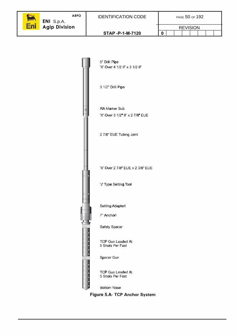
ARPO
ENI S.p.A.Agip Division
IDENTIFICATION CODE PAGE 50 OF 192
REVISIONSTAP -P-1-M-7120 0
Figure 5.A- TCP Anchor System
ARPO
ENI S.p.A.Agip Division
IDENTIFICATION CODE PAGE 51 OF 192
REVISIONSTAP -P-1-M-7120 0
5.7. MISFIRE PROCEDURES
In the event of any total misfire or no-fire of the perforating guns, it is imperative that theperforating contractor is contacted immediately. The perforating contractor should, afterassessing the sequence of events, prepare a detailed procedure for recovery of the guns.
5.7.1. Mechanical Firing Head
1) Due to the nature of the mechanical system, the guns can be fired during anysubsequent fishing operations and this should be taken into account.
2) Adequate time should be allowed for the detonating bar to reach the firing headbefore a misfire is suspected. Allow twice the estimated time. If the guns do not fire, itis probably due to the detonating bar hanging up on debris on top of the firing head,or in a restriction further up the tubing.
3) Once a misfire has been established fishing operations will commence in an attemptto fire the guns. Record the following data:
• OD of fishing neck• ID of the smallest restriction in the string• Depth of the firing head.• Length of the detonating bar• Distance from the top of the firing head to the communication ports in the tubing.
4) Ensure that the following slickline tools are available and on site:
• Overshot designed to catch the fishing neck• 11/4 ins OD bailer• 11/4 ins lead impression block• Chisel point bailer bottom for the 11/4 ins bailer.
5) Make sure that the length of the lubricator is adequate to accommodate thetoolstring and the length of the detonating bar if recovered.
6) Confirm the distance from the firing head to the ports in the tubing string. Thisshould be sufficient to allow both the toolstring and detonating bar to remainbelow the ports.
7) Rig up slickline and prepare the toolstring with an overshot to catch the detonatingbar.
8) When running in hole confirm the fluid level in the well. Record this depth.
9) Shot detection equipment will be used and it should be monitored during all fishingoperations and attempts to fire the guns.
10) When the detonating bar is located, spud down as hard as possible. Do not pick upstraight away. If the bar moves, chase it to the firing head as quickly as possible. Thiswill ensure that the slickline tool will not be above the entry ports (should the guns fire)and be blown up the well. Repeat this process three times.
11) If the guns do not fire fish the detonating bar and pull out of the hole.
12) Rig up with 11/4 ins bailer and ‘Chisel Point’ bailer bottom. The bailer should bedressed to a sharp point.
ARPO
ENI S.p.A.Agip Division
IDENTIFICATION CODE PAGE 52 OF 192
REVISIONSTAP -P-1-M-7120 0
1) Run in the hole and jar down as hard as possible on the firing pin. Again ensure thatthe toolstring does not get pulled above the entry ports. Pull out of the hole andinspect the leading edge of the chisel point. Damage will indicate whether or notsomething hard (firing pin or foreign object) is being struck.
2) Carefully observe for any material recovered in the bailer, it may indicate what ispreventing the detonating bar from reaching the firing pin. Fine black powderydeposits are an indication that the guns have fired and will be associated with a smellof burnt cordite. Hydrocarbons may also be present.
3) Repeat bailing operations until it is certain that the bailer is striking the firing pin.
4) If it becomes obvious that the bailer is striking something other than the firing pin, runa lead impression block.
5) Check the fluid level in the well during every wireline run. Monitor carefully forlosses/gains.
6) When it has been determined that the firing pin has been struck, and the guns havenot fired, pull out of the hole with the drop bar.
7) In the event that a retrievable head has been used, this should be retrieved at thispoint and inspected.
• If it has not fired, run another firing head on slickline and repeat the procedure.• If the head has fired, rig down wireline.
8) Top up the well with fluid, and if not already done so, rig up circulating lines from thecement unit to the production string. Attempt to pump into the formation to confirmthat the guns have not fired. The leak-off pressure should be taken into consideration.
9) Unseat the packer and circulate the well contents to kill fluid. Circulate and conditionthe brine. Prepare to pull the completion and retrieve the guns.
10) Once the firing head has been retrieved the guns are safe, and can be pulled from thewell.
11) If it proves impossible to retrieve the detonating bar, the string and guns will have tobe pulled. This is potentially very hazardous. Refer to base and seek the advice of theTCP gun manufacturer and senior Company personnel. No further action should betaken without written instructions endorsed by all parties concerned.
5.7.2. Hydraulic Firing Head
The hydraulic firing head (tubing pressure) is normally run with a time delay to allowunderbalance conditions to be re-established after the tubing pressure is increased.
1) If no indication of the guns firing is observed, twice the duration of the time delayshould be allowed before repeating.
2) If the guns will not fire at the design pressure, increase the pressure (in increments of500 or 1,000psi) and re-apply, allowing twice the time delay before repeating.
3) Monitor any fluid gains or losses.
4) Monitor the shot detection equipment. In the event that it is established that the gunswill not fire, the TCP representative on location will evaluate the situation inconjunction with the Well Operations Supervisor. Both Eni-Agip and the TCP companyonshore will be consulted. A detailed procedure will be prepared based on the currentstatus of the operation, prior to any further action.
ARPO
ENI S.p.A.Agip Division
IDENTIFICATION CODE PAGE 53 OF 192
REVISIONSTAP -P-1-M-7120 0
5.7.3. Fixed Hydraulic Firing Head
With this type of firing head, a misfire is potentially the most hazardous situation and bothEni-Agip and the TCP contractor operations management staff must endorse any furtherinstructions or procedures for recovery of the guns.
5.7.4. Retrievable Hydraulic Firing Head
The firing head must be recovered using slickline, thus disarming the guns prior to theirrecovery. The TCP contractor will at this point must provide a procedure based on thecurrent status of the operation. Once the firing head has been recovered, the guns areentirely safe and can be retrieved from the well.
5.8. COILED TUBING PERFORATING
Perforating procedures using coiled tubing has been extensively employed to fully takeadvantage of perforating long intervals underbalanced and possibly in high angle orhorizontal wells. The procedures used are contractor equipment and field specific and needto be drafted for each individual situation.
ARPO
ENI S.p.A.Agip Division
IDENTIFICATION CODE PAGE 54 OF 192
REVISIONSTAP-P-1-7120 0
6. GRAVEL PACKING PROCEDURES
There are two gravel pack applications, one for open hole completions and the other forinside cased hole. This section contains the common procedures for both open hole andinternal gravel packing.
For perforating gun applications and gun design options, refer to the Company CompletionsDesign Manual.
6.1. GRAVEL PLACEMENT OBJECTIVES
It is imperative that the perforation tunnels and the screen to casing annulus, or screen toopen hole annulus, be completely filled with clean, highly permeable gravel pack sand. Inaddition a gravel reserve above the top perforation should be created to allow for anysettling of the pack that may occur. Completely filled perforation tunnels and annular areasresult in minimal pressure losses through the gravel packed completion, which in turnenables maximum productivity.
While pumping the gravel pack slurry, after it passes the crossover tool, there are only twopaths for the carrier fluid to flow. One flow path for the fluid is through the gravel packscreen then returning to surface. The other flow path for the fluid is through leak off to theformation.
In internal gravel packs, carrier fluid leak off to the formation through the perforations isessential to carry the gravel pack sand into and efficiently pack off the tunnels. If insufficientleak off is caused, the perforations will not be filled with gravel pack sand. However on theother hand, if excessive leak-off is encountered, the gravel pack sand may bridgeprematurely in the annulus, resulting in voids throughout the length of the gravel pack.
These voids may fill from above due to gravity settling of the pack but if the voids do not fillwith gravel pack sand, two results may occur:
• Produced sand will erode holes in the screen and the gravel pack will fail.• The voids will fill with much lower permeability formation sand and productivity
will be reduced.
6.2. SCREEN SIZE
The sand grade used in gravel pack designs is selected usually to be 5 to 6 times greatersize than the average formation sand particle size which is determined by sieving. Thespace between the wires in a screen are termed the ‘Gauge’ which in turn is selectedaccording to the grade of pack sand the screen must retain. The gauge is usually 0.5 - 0.9.of the smallest pack sand grain. Tables of the various sand grades, grain sizes andrecommended screen gauge is available from any of the gravel pack service providers.
The OD of the screen is selected according to the production casing size in order that thereis enough annulus clearance whilst running and fishing with an overshot, if necessary. Therecommended annulus clearance is circa 1.000ins. The Well Operations Supervisor shouldcheck the screen clearance and fishing capability before running.
ARPO
ENI S.p.A.Agip Division
IDENTIFICATION CODE PAGE 55 OF 192
REVISIONSTAP -P-1-M-7120 0
6.3. GRAVEL CALCULATIONS
The fluids programme to be used will be detailed in the Completions Programme includingpre-pad and slurry recipes. The slurry and sand volumes contained in the programme needto be verified before the gravel pack operations using the calculations given below.
6.3.1. Sand Volume Required
The first stage of a sand volume calculation is to prepare a spreadsheet with informationabout the well geometry and should focus on the spaces to be occupied by pack sand. Thestandard issue of pack sand is in 100lb sacks which occupies 1ft3, therefore the volume ofthe spaces should also be calculated in ft3.
This calculation depends on whether it is an open hole or internal gravel pack job and if asump packer is used.
Open Hole
Step 1
Calculate the total annular volume outside the screen to the planned height of the sand:
Total Annular Volume = Screen/Hole Annulus + Blank Pipe/Hole Annulus + 40-60ftvolume surplus
If the planned sand height was up into the casing, this reduced volume would need to beconsidered.
Step 2
Calculate the volume of sand in the rat hole, if applicable:
Hole volume below screens.
Step 3
Calculate total sand required:
Add the calculated volumes from steps 1 and 2.
Internal
Step 1
Calculate the annular volume outside the screen to the planned height of the sand:
Screen/Casing Annulus + Blank Pipe/Casing Annulus + 40-60ft volume surplus
Step 2
Calculate the volume of sand in the rat hole, if applicable:
Hole Volume below screens
Step 3
Calculate the volume required for the perforations:
Length of Perforations x Volume factor (usually 1ft3/ft)
Calculate total sand required:
Add the calculated volumes from steps 1 2 and 3.
ARPO
ENI S.p.A.Agip Division
IDENTIFICATION CODE PAGE 56 OF 192
REVISIONSTAP -P-1-M-7120 0
Total Sand Weight
Total Volume ft3 x 100lb/ft3
6.3.2. Carrier Fluid Volume
The weight of carrier fluid is dependent upon the weight of fluid required to control the well.An amount of the carrier fluid is usually set aside for use as pre-pad and sometimes a post-pad or push pad to segregate if from the other wells fluids. The pre-pad is normally about10bbls and the post pad 5bbls.
The total volume of the slurry then depends upon how much sand can be carried by thecarrier fluid at for that particular weight of fluid to be used. This will be confirmed in the wellprogramme or by the gravel pack technician. The total volume (galls) of slurry then requiredis simply the total sand volume required divided by the sand carried per gal.
Total Slurry Volume (galls) = Total Sand Volume lbs/Sand Volume (lbs per gall)
Some of the early part of the gravel pack procedure should be conducted in the squeezeposition to pack it into the perforations. If no losses are caused, there will be no sandpacked to the end of the tunnels.
6.4. COMMON GRAVEL PACK PROCEDURES
Refer to the well clean up procedures in section 4.
1) Thoroughly clean all rig circulating system equipment. Prepare a dedicated active pitfor filtered completion fluid.
2) Filter the completion fluid with a Diatomaceous Earth (DE) filter press anddownstream absolute cartridge filters to remove all potential damaging particles.Pump from the storage pit and return the filtered completion fluid into the active cleanpit.
Note: All fluids pumped downhole during the completion phase must be filteredprior to use.
3) Run in hole with casing scrapers and a short open ended tailpipe on workstring.Thoroughly scrape the casing through all intervals to be perforated and all packersetting depths (Refer to section 4.2).
4) Displace the wellbore fluid with the filtered completion fluid. Circulate with filteredcompletion fluid till returns are clean according to the well programme.
5) Rig up electric line. Make gauge ring and junk basket run to TD. Pull out of the holewith the gauge ring and junk basket, if necessary.
6) Verify screen gauge and gravel delivered is correct according to the well programme.
ARPO
ENI S.p.A.Agip Division
IDENTIFICATION CODE PAGE 57 OF 192
REVISIONSTAP -P-1-M-7120 0
6.5. OPEN HOLE GRAVEL PACK PROCEDURE
The procedure described herein is based on Baker’s gravel pack systems.
1) Pick up the hole opener and trip to the bottom of the production casing.
2) Establish circulating rates and pressures, then drop the activating ball to open thehole opener.
3) Drill the open hole length with the hole opener.
4) Pull out of the hole.
5) Conduct any stimulation treatment that may be necessary for the particular formation(this may be done post gravel pack, if desired).
6) Ensure the fluid in the hole has been properly filtered and cleaned before running thegravel pack (Refer to section 6.3.2 above).
7) Drift all BHA tubulars including GP equipment and wash pipe.
8) Pick up and assemble the gravel pack assembly in the rotary table as follows, frombottom up, running at a slow speed to prevent damage to the packing element and toprevent prematurely setting the packer.
• Blank bull nosed plug• Sand screens• Blank pipe.
9) Run flush joint washpipe inside, and to the bottom of, the screen and blank pipe. Theassembly consisting of the following items is then picked up and made up onto thescreen assembly.
• Knock Out Isolation Valve• Blank pipe• Shear Out Safety Joint• Indicating Sub• Crossover Sub• Gravel Pack Extension with Sliding Sleeve• Gravel Pack Packer.
10) The gravel pack service toolstring assembly is then made up to the previousassembly:
• Shifting Tool• Gravel Pack Crossover Tool• Hydraulic Setting Tool.
Note: Apply thread compound sparingly to the pin ends of the connections only.
11) Run in the hole slowly with the completion assembly (90sec per 90ft stand). Set downinto, and pick up gently out of, the slips.
12) Record the pick-up and slack-off weights when reaching the packer setting depth.
13) Once the assembly is positioned on depth, rig up the gravel infuser pumpingequipment, manifold and lines. Test to 5,000psi.
14) Establish circulation, record circulating pressure and drop the packer setting ball.Allow time for ball to gravitate to the ball seat in the crossover tool, roughly5min/1,000ft.
ARPO
ENI S.p.A.Agip Division
IDENTIFICATION CODE PAGE 58 OF 192
REVISIONSTAP -P-1-M-7120 0
1) Set the packer by slowly pressuring up the workstring according to the steps andpressures stated in the well programme.
2) Verify slip anchoring of the packer by alternately setting down and picking up 10,000-15,000lbs weight.
3) Slack off to the neutral position and test the packer by pressuring the casing to1,000psi. for 5min.
4) Since 1,000psi annular pressure releases the crossover tool from the packer, thecrossover tool may now be snapped out of the packer. Alternatively, the crossovertool may be released from the packer by turning 15 rotations to the right at the packerdepth holding a slight upstrain.
5) Raise the crossover tool to the reverse circulating position. Apply the appropriateworkstring pressure to shear the ball seat in the crossover tool. Break circulation in thereverse direction at 3bpm and record the pump pressure.
6) Pickle the workstring by circulating the pickling agent to the end of the workstring.Reverse circulate 1
1/2 workstring volumes of filtered completion fluid until returns are
clean.
7) Lower the crossover tool and set down 10,000lbs on the packer. This is the squeezeposition, mark the pipe at the rotary table level. Establish injection pressures at 3, 2, 1,and
1/2bpm. Do not exceed the formation fracture pressure.
Note: If injectivity is low, an acid stimulation treatment may be conducted priorto performing the gravel pack.
22) Raise the crossover tool to neutral weight plus an additional 2ft. This is the circulatingposition, mark the pipe at the rotary table level. Establish circulating pressures at 3, 2,1, and
1/2bpm. Monitor the return rate with a flowmeter to determine the leak-off rate to
the zone. If full returns are observed, partially close the annular BOP to hold back-pressure and induce leak-off. Do not exceed the formation fracture pressure.
23) Raise the crossover tool to the reverse circulating position. Infuse gravel pack sandinto completion fluid at the desired mix ratio and pump a circulating rate of 3bpm. Apump rate of 3bpm must be maintained to achieve a fluid velocity of 500ft/min in 3
1/2”
workstring.
24) When the sand is 5-10bbls above the packer, lower the crossover tool into thecirculating position. Continue displacing the gravel with filtered completion brine untilan initial pressure increase is observed due to gravel covering the screens. Whilepumping, allow the pressure to build to 1,500-2,500psi. over the initial circulatingpressure at a given rate. Maintain this sandout pressure while slowing the pump rateto 2, 1, and
1/2bpm. Allow the pressure to bleed off to the formation. Calculate the
gravel height above the screen top using the linear flow equation.
25) Do not re-stress the pack. Close the annular BOP and apply 500psi to the annulus.Raise the crossover tool to the reversing position. Reverse out excess gravel plus twoworkstring volumes. Divert the gravel returns to the slurry dehydration tank anddetermine the volume of gravel reversed out. The volume of gravel placed can thenbe calculated by subtracting the volume reversed out and the screen/open hole, blankpipe/open hole and blank pipe/casing annular volumes from the total volume of gravelpumped.
ARPO
ENI S.p.A.Agip Division
IDENTIFICATION CODE PAGE 59 OF 192
REVISIONSTAP -P-1-M-7120 0
1) To test the gravel pack, lower the crossover tool into the circulating position andattempt to circulate at the same rate and pressure achieved earlier. If sandoutpressure cannot be achieved, mix and pump another batch of gravel. Reverse outexcess gravel. Repeat this step until final sandout occurs.
2) Pull out of the hole with the service toolstring.
3) Revert to the completion procedures in the completion programme.
6.6. CASED HOLE GRAVEL PACK PROCEDURE
The procedure described herein is based on Baker’s gravel pack systems.
1) Prepare the hole as per section 6.3.2.
2) Run in hole with the sump packer on electric line. Correlate with the GR/CCL to thereference log and set the packer at approx. 6ft below the planned depth of the bottomperforation. Pull out of the hole and rig down the electric line.
3) Pick up the perforating assembly and run in the hole (Refer to section 5).
Note: Use a Tubing Conveyed Perforating system with the highest possible shotdensity (typically 12spf), with Gravel Pack or ‘Big Hole’ charges.
4) Establish the desired underbalance.
Note: This operation should be performed with the underbalance stated in thewell programme (normally 500-1,000psi depending on the formationstrength.
5) Verify the proper positioning of the perforating guns by tagging the sump packer andspace out the string at the correct depth.
6) Set the packer.
7) Rig up the control head and surface lines (if on a floater this will be done before step6 above).
8) Detonate the perforating guns by appropriate procedure.
9) Flow the well to sufficiently remove all debris from the perforations.
10) Reverse circulate two workstring volumes with filtered completion fluid to stabilise thewell. Continue circulating and filtering until returns are clean.
11) Monitor the well to determine if it has stabilised. Record any fluid losses or gains. Ifnecessary to control fluid loss, spot a fluid loss control pill.
12) Unseat the packer and reciprocate the string to fully release the packer and repeatone more complete circulation.
13) Pull out of the hole with the TCP assembly, monitoring for fluid losses.
14) If there is evidence of formation sand in the returns, pick up and run a scraper with atailpipe to enter and wash down to the sump packer.
ARPO
ENI S.p.A.Agip Division
IDENTIFICATION CODE PAGE 60 OF 192
REVISIONSTAP -P-1-M-7120 0
1) Pick up and assemble the gravel pack assembly in the rotary table as follows, frombottom up, running at a slow speed to prevent damage to the packing element and toprevent prematurely setting the packer.
• Snap Latch Seal Assembly• Sand screens• Blank pipe
2) Run flush joint washpipe inside, and to the bottom of, the screen through the blankpipe. The assembly consisting of the following items is then picked up and made uponto the screen assembly.
• Knock Out Isolation Valve• Shear Out Safety Joint• Crossover Sub• Gravel Pack Extension with Sliding Sleeve• Gravel Pack Packer.
3) The gravel pack service toolstring assembly is then made up to the previousassembly:
• Shifting Tool• Gravel Pack Crossover Tool• Hydraulic Setting Tool.
Note: Apply thread compound sparingly to the pin ends of the connections only.
18) Run in hole slowly with the completion assembly (90sec per 90ft stand). Set downinto, and pick up gently out of, the slips.
19) Record the pick-up and slack-off weights when reaching the packer setting depth.
20) Record pick-up and slack-off weights one stand above the sump packer. Tag thesump packer and set down sufficient weight to force the latch of the snap latch toengage the packer. If desired, the latch may be snapped out of the packer with pull toverify correct operation.
21) Once the assembly is positioned on depth, rig up the gravel infuser pumpingequipment, manifold and lines. Test to 5,000psi. Establish circulation, recordcirculating pressure and drop the packer setting ball. Allow time for ball to gravitate tothe ball seat in the crossover tool, roughly 5min/1,000ft.
22) Set the packer by slowly pressuring up the workstring according to the steps andpressures stated in the well programme.
23) Verify slip anchoring of the packer by alternately setting down and picking up 10,000-15,000lbs weight.
24) Slack off to the neutral position and test the packer by pressuring the casing to1,000psi for 5min.
25) Since 1,000psi annular pressure releases the crossover tool from the packer, thecrossover tool may now be snapped out of the packer. Alternatively, the crossovertool may be released from the packer by turning 15 rotations to the right at the packerdepth with a slight upstrain.
ARPO
ENI S.p.A.Agip Division
IDENTIFICATION CODE PAGE 61 OF 192
REVISIONSTAP -P-1-M-7120 0
1) Raise the crossover tool to the reverse circulating position. Apply the appropriateworkstring pressure to shear the ball seat in the crossover tool. Break circulation in thereverse direction at 3bpm and record the pump pressure.
2) Pickle the workstring by circulating the pickling agent to the end of the workstring.Reverse circulate 1
1/2 workstring volumes of filtered completion fluid until returns are
clean.
3) Lower the crossover tool and set down 10,000lbs on the packer. This is the squeezeposition, mark the pipe at the rotary table level. Establish injection pressures at 3, 2, 1,and
1/2bpm. Do not exceed the formation fracture pressure.
Note: If injectivity is low an acid stimulation treatment may be desired prior toperforming the gravel pack.
29) Raise the crossover tool to neutral weight plus an additional 2ft. This is the circulatingposition, mark the pipe at the rotary table level. Establish circulating pressures at 3, 2,1, and
1/2bpm. Monitor the return rates with a flowmeter to determine the leak-off rate
to the zone. If full returns are observed, partially close the annular BOP to hold back-pressure and induce leak-off. Do not exceed the formation fracture pressure.
30) Raise the crossover tool to the reverse circulating position. Infuse gravel pack sandinto completion fluid at the desired mix ratio and at a circulating rate of 3bpm. A pumprate of 3bpm must be maintained to achieve a fluid velocity of 500ft/min in 3
1/2”
workstring.
31) When the sand is 5-10bbls above the packer, lower the crossover tool into thecirculating position. Continue displacing the gravel with filtered completion brine untilan initial pressure increase is observed due to gravel covering the screens. Whilepumping, allow the pressure to build to 1,500-2,500psi over the initial circulatingpressure at a given rate. Maintain this sandout pressure while slowing the pump rateto 2, 1, and
1/2bpm. Allow the pressure to bleed off to the formation. Calculate the
gravel height above the screen top using the linear flow equation.
32) Do not re-stress the pack. Close the annular BOP and apply 500psi to the annulus.Raise the crossover tool to the reversing position. Reverse out excess gravel plus twoworkstring volumes. Divert the gravel returns to the slurry dehydration tank anddetermine the volume of gravel reversed out. The volume of gravel placed behind thecasing can then be calculated by subtracting the volume reversed out and thescreen/casing and blank pipe/casing annular volumes from the total volume of gravelpumped.
33) To test the gravel pack, lower the crossover tool into circulating position and attemptto circulate at the same rate and pressure achieved earlier. If sandout pressurecannot be achieved, mix and pump another batch of gravel. Reverse out any excessgravel. Repeat this step until final sandout occurs. Pull out of the hole with the servicetoolstring.
34) Revert to the completion procedures in the completion programme.
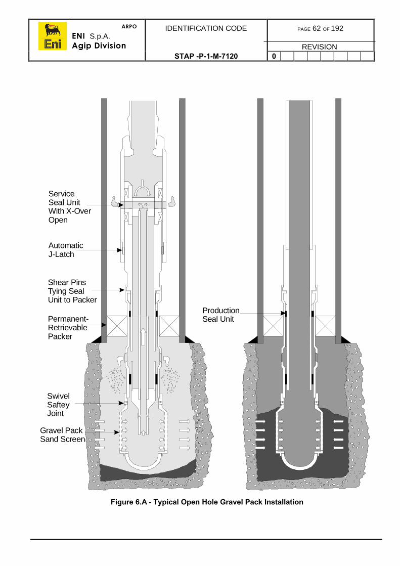
ARPO
ENI S.p.A.Agip Division
IDENTIFICATION CODE PAGE 62 OF 192
REVISIONSTAP -P-1-M-7120 0
Figure 6.A - Typical Open Hole Gravel Pack Installation
ServiceSeal UnitWith X-OverOpen
AutomaticJ-Latch
Shear PinsTying SealUnit to Packer
Permanent-RetrievablePacker
Gravel PackSand Screen
SwivelSafteyJoint
ProductionSeal Unit
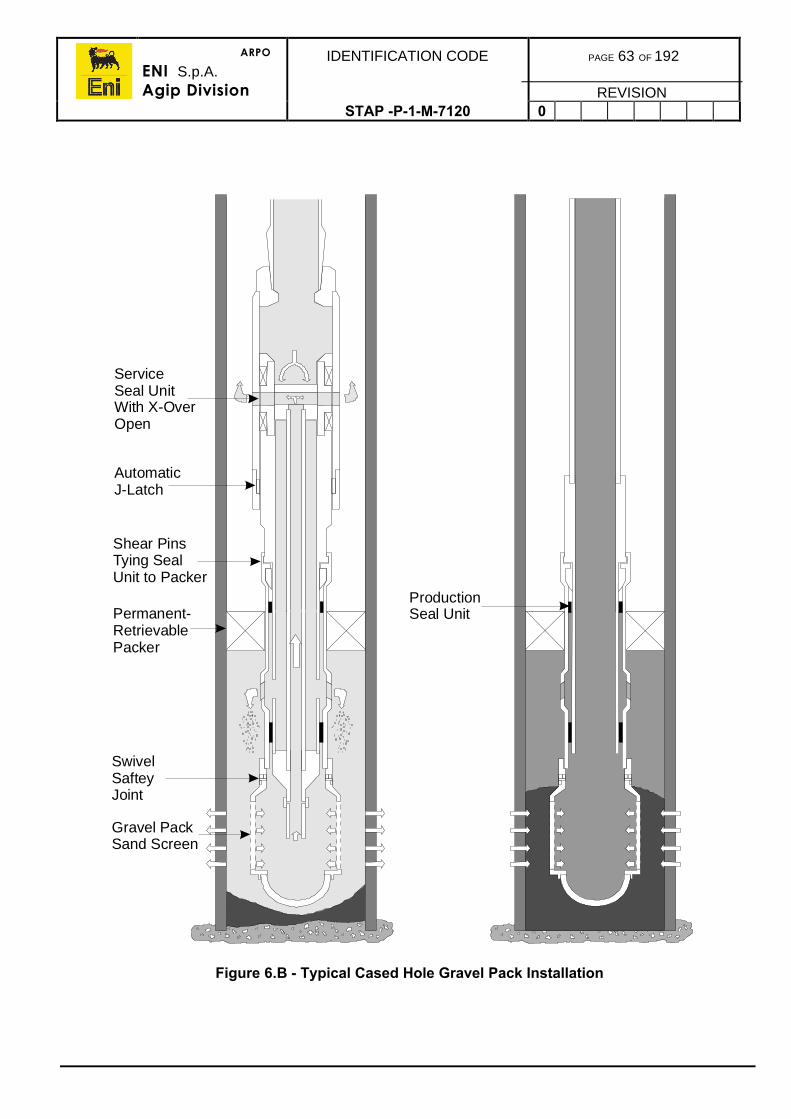
ARPO
ENI S.p.A.Agip Division
IDENTIFICATION CODE PAGE 63 OF 192
REVISIONSTAP -P-1-M-7120 0
Figure 6.B - Typical Cased Hole Gravel Pack Installation
ServiceSeal UnitWith X-OverOpen
AutomaticJ-Latch
Shear PinsTying SealUnit to Packer
Permanent-RetrievablePacker
Gravel PackSand Screen
SwivelSafteyJoint
ProductionSeal Unit
ARPO
ENI S.p.A.Agip Division
IDENTIFICATION CODE PAGE 64 OF 192
REVISIONSTAP-P-1-7120 0
7. PACKER INSTALLATION
In some completion programmes, packers may be set on electric wireline, such as wheninstalling reference packers for gravel packs or using a packer as a plug. Normally it ispreferred to install a production packer on the completion tubing string in order to obtainsingle trip installation saving unwarranted wireline trips and, hence, reduce cost. Refer tothe Completion Design Manual for various packer completion designs and installationmethods.
An advantage of setting a packer on wireline is it is quick and simple and accurate setting.This ensures that the packer is not set across a casing coupling or can be used as areference for TCP gun depth correlation. A disadvantage, other than trip cost saving, is thatthe packer is not pressure tested until the tubing string is installed.
Packers to be set in highly deviated wells may be installed on a workstring where wirelinewould not reach. The packers set on a workstring can be set mechanically or hydraulicallyby applying pressure to the workstring.
Selective completions may have a number of tubing retrievable type packers installed in asingle trip which are set in sequence.
Eni-Agip’s policies for the use of retrievable and permanent packers is fully outlined in theCompany’s Completion Design Manual.
Both tubing and wireline set packer installation procedures are described in this section.
7.1. HOLE PREPARATION
Before running any packer (wireline or tubing installed), a junk basket with a gauge ringshould be run to below the depth at which the packer is to be set. This is to ensure that thepacker can successfully reach the setting depth. The gauging/junk basket procedure is:
1) Rig up the electric line for running in cased hole.
2) Confirm that the gauge ring is the correct size for the production casing or liner.
3) Run the junk basket and gauge ring slowly observing the CCL to confirm that the toolis moving at the same speed as the cable.
4) If the junk basket is run to TD, when pulling out of the hole, it is important not to slackoff on the cable as this will open the junk basket and release the contents. Speed andtension should be closely monitored while pulling out.
5) If the junk basket is full of junk, repeat the procedure until no more debris isrecovered.
7.2. WIRELINE PACKER SETTING PROCEDURE
In this method the packer is run on a setting tool and is set by application of controlledpressure from a slow burning powder charge acting through a piston which, in turn, forcesthe packer through its setting sequence. When the sequence is completed the packersetting tool is automatically released from the packer and is confirmation of correctoperation.
The procedures given below are generic and not specific to any particular packermanufacturer, therefore alterations to these procedures may be necessary to suit aparticular packer.
ARPO
ENI S.p.A.Agip Division
IDENTIFICATION CODE PAGE 65 OF 192
REVISIONSTAP -P-1-M-7120 0
7.2.1. Running Procedure
As the setting tool is operated using an explosive charge, radio silence will be requiredwhen making up and running the tool. Also, when the tool has been fired the body willcontain high pressure gas, hence special care will have to be taken when it is being riggeddown at surface.
1) The Company Supervisor shall verify that the completion equipment, including thepacker system, corresponds to the details in the completion programme and has theappropriate correct part numbers, serial numbers and certification.
2) Assemble the packer adapter kit and setting tool. Each packer will have anappropriate packer kit to fit between the specific type and size of packer and the typeand size of setting gun.
3) Rig down the gauge ring/junk basket.
4) Pick up the lower packer tailpipe assembly and set it in the rotary table installing acollar clamp above the slips as there is little weight at this time.
5) Pick up the other tailpipe sub-assemblies and make up them up in sequenceaccording to the well programme.
6) Make up the packer to the top of the packer tailpipe.
7) Install a plug by wireline in the packer tailpipe landing nipple, fill up the assembly withbrine.
8) Install the packer test adapter and pressure test the packer/packer tailpipe assemblyto the pressure stated in the Completion Programme.
9) Remove the test adapter and retrieve the wireline plug.
10) Obtain radio silence and make up the cable head to the setting tool/packer assembly.
11) Pick-up the packer running tool assembly and make it up to the packer.
12) Pick up the assembly and remove the collar clamp and pull the slips.
13) Conduct a weight check.
14) Run in the hole at the recommended speed given by the packer supplier or thelogging contractor whichever is applicable.
15) Make a correlation logging pass over a suitable interval and record the GR/CCL log.
16) Correlate the depth measurements to the reference log depths.
17) Position the assembly at the correct setting depth.
18) After the Logging Engineer and Well Operations Supervisor have satisfied themselvesthat the toolstring is at the correct depth, the setting charge will be fired.
Note: Do not tag the packer after setting as the adapter kit may become stuck inthe packer, resulting in a fishing job.
19) Pull the tool back to surface carefully, ensuring that all radio silence procedures arefollowed.
20) When the toolstring is back at surface, inspect the adapter kit and setting tool to verifythe proper setting of the packer, handling carefully in case there has been a misfire.
21) Release any pressure from the setting tool and rig down.
ARPO
ENI S.p.A.Agip Division
IDENTIFICATION CODE PAGE 66 OF 192
REVISIONSTAP -P-1-M-7120 0
7.3. TUBING INSTALLED PACKER SETTING PROCEDURE
If the packer is to be set on a workstring, a packer adapter is required to allow connectionbetween the packer and the workstring. If the packer is to be set by hydraulic pressure, asetting tool similar to that describe for wireline setting is required and attached to theworkstring.
If the packer is to be installed on the completion tubing string, all the completioncomponents will be installed in the string as it is run. This includes the packer tailpipe,tubing movement device, landing nipples, circulating devices, SSSV, etc.
7.3.1. Workstring Running Procedure
The hole will be gauged according to section 7.1.
1) The Company Supervisor shall verify that the completion equipment, including thepacker system, corresponds to the details in the completion programme and has theappropriate correct part numbers, serial numbers and certification.
2) Assemble the packer adapter kit (and setting tool, if hydraulic set). Each packer willhave a appropriate packer kit to fit between the specific type and size of packer andthe type and size of setting gun or workstring.
3) Pick up the lower packer tailpipe assembly and set it in the rotary table installing acollar clamp above the slips as there is little weight at this time.
4) Pick up the other tailpipe sub-assemblies and make up them up in sequenceaccording to the well programme.
5) Make up the packer to the top of the packer tailpipe.
6) Install a plug by wireline in the packer tailpipe landing nipple, fill up the assembly withbrine.
7) Install the packer test adapter and pressure test the packer/packer tailpipe assemblyto the pressure stated in the Completion Programme.
8) Remove the test adapter and retrieve the wireline plug.
9) Pick up the setting tool and first joint of tubing and make up onto the packer.
10) Pick up the assembly and remove the collar clamp and then the slips.
11) Run in the hole at the recommended speed given by the packer supplier.
12) Trip to depth according to pipe measurement.
13) If accuracy is required, rig up electric line and run a GR/CCL and correlate theworkstring to the casing.
14) Set the packer mechanically or hydraulically according to the packer settingprocedure.
15) If possible, pressure test the packer according to the programme.
16) Shear off the workstring from the packer and pull the workstring. The hydraulicrunning tool usually self releases from the packer similar to the wireline settingprocedure, therefore do not set back down to check the packer otherwise the adaptermay be come stuck.
17) Pull the workstring with the adapter kit back to surface and check the shear pins toverify the setting of the packer.
18) Rig down.
ARPO
ENI S.p.A.Agip Division
IDENTIFICATION CODE PAGE 67 OF 192
REVISIONSTAP -P-1-M-7120 0
7.3.2. Completion String Running Procedure
The hole will be gauged according to section 7.1.
1) The Company Supervisor shall verify that the completion equipment, including thepacker system, corresponds to the details in the completion programme and has theappropriate correct part numbers, serial numbers and certification.
2) Pick up the lower packer tailpipe assembly and set it in the rotary table installing acollar clamp above the slips as there is little weight at this time.
3) Pick up the other tailpipe sub-assemblies and make up them up in sequence.
4) Make up the packer to the top of the packer tailpipe.
5) If it is felt necessary to pressure test the packer tailpipe, run a wireline plug andconduct the test as per the manufacturer’s procedure.
6) Pick up the other packer accessories and install onto the packer.
7) Pick up the assembly and remove the collar clamp and then the slips.
8) Run in the hole and set the slips and collar clamp again.
9) Pick up the first joint of tubing and make up onto the string.
10) Run in the hole at the recommended speed given by the packer supplier installing allcompletion components.
11) Trip to depth according to pipe measurement.
12) Rig up electric line and run a GR/CCL and correlate the string depth, hence packerdepth to the casing. If the tubing is high chrome content, consideration must be givento a different method of depth correlation
13) Determine spacing out for the tubing hanger and install pup joints and the tubinghanger.
14) Trip into the hole, record string weight and place the packer on the correct depth.
15) Conduct a tubing string gauging procedure to confirm nipple depths and sizes.
16) Either, drop the packer setting ball or rig up wireline and run the packer setting plug/standing valve (Refer to the Wireline Procedures Manual).
17) Rig up the pump line to the test head and fill up the string with brine.
18) Pressure up on the string to set the packer, according to the manufacturer’sprocedure.
19) Set the tubing hanger, if not already set, and conduct all other completion pressureand function test procedures.
20) Pull the packer setting plug/standing valve, if necessary.
21) Continue with the completions programme.
ARPO
ENI S.p.A.Agip Division
IDENTIFICATION CODE PAGE 68 OF 192
REVISIONSTAP-P-1-7120 0
8. COMPLETION INSTALLATION
The procedures in this section describe the procedures for equipment pre-installationchecking and completion installation.
8.1. CARBON STEEL AND PLASTIC COATED TUBING
1) Tally and number the tubing joints as soon as they are unloaded from the transport.
2) On the pipe rack remove the thread protectors to allow inspection and cleaning.
3) All pin and box ends should be inspected for damage paying particular attention to theseal areas.
4) All joints must be drifted with a suitable tubing drift. Drifts should be 42ins long tostandard API specification, blunt nosed, and plastic coated or with rubber ends toprevent damaging the seal areas on the connections.
5) Rejected joints should be clearly marked with red paint and prepared for back-loadingas per API RP5A5.
6) While the tubing is being laid out on the pipe deck, the pin and box threads should becleaned with, either, a suitable detergent, steam, or high pressure water. Avoid usingwater, if at all possible. Ensure the detergents used are in accordance with personnelSafety Policies.
7) When preparing a tubing tally, measurements should be carried out twice, preferablyby two independent personnel with different measuring tapes. When a comparison ofthe measurements is made, if any length is off by more than 0.01ft, recheck the tally.Simple errors of +/- 1ft are sometimes made where the tape has been mis-read.
8.2. CHROME TUBULARS
Chrome tubulars are extremely susceptible to galling and to local cold working if improperlystressed or impacted during shipping and handling.
Excessive bending during lifting of single joints, or bundles of joints, can also causeunacceptable levels of stress to be imparted.
Improper handling can lead to an increase in hardness or change in mechanical propertieswhich may result in detrimental forms of corrosion such as sulphide stress corrosioncracking and uneven corrosion.
8.2.1. Transportation
Handling, transportation, and temporary storage of tubular goods will comply with Section 3of API RP 5C1.
ARPO
ENI S.p.A.Agip Division
IDENTIFICATION CODE PAGE 69 OF 192
REVISIONSTAP -P-1-M-7120 0
8.2.2. Transport From The Mill
Chrome tubulars will be dispatched from the mill in special transport frames. These will beloaded into wooden crates for shipment. The tubulars will be covered by nylon sheets, andwrapped with Drilltec Econorap. The transport boxes are designed to prevent movement of,and contact between individual joints during transportation. The wrapping will also minimisethe risk of the tubing coming into contact with seawater during transportation. The transportframes will be removed from the wooden crates prior to shipment offshore.
Note: Webbing type strops for cargo handling is not permitted.
8.2.3. Road Transport
• The transport boxes will be properly loaded, and supported along their entirelength.
• Chrome tubulars will not be removed from their transport frames until arrival onthe installation.
• Security of the bolts on the transport frames will be checked by a Companyrepresentative, or an approved designate, before lifting to ensure that thetubulars are secured, and so prevent movement of the tubulars within thetransport frames.
• The transport frames will be secured using nylon straps.• Any loose tubing should also be secured by nylon straps.
8.2.4. Marine Transport
• The transport frames will be arranged on deck in order to prevent longitudinalmovement.
• Protection, such as tyres or heavy rope, will be used to protect the transportframes from other cargo.
• The transport frames will not be stacked more than three high.• No other cargo will be placed on top of the transport frames.
8.2.5. Handling At The Wellsite
1) Chrome tubulars must not be allowed to contact other metallic material, includingsupports and tubulars of the same material.
2) Chains, monkey wrenches, hooks, shackles, etc. will not be used for handling chrometubulars.
3) Where metal impact or handling devices have inadvertently been used the tubing jointwill be set aside for further checking.
4) Only lift tubulars with nylon strops.
5) Plastic supports will be used to support chrome tubulars and prevent rolling. Woodand rope are not recommended as they tend to retain moisture, and may becomecontaminated with chlorine or other chemicals harmful to chrome tubulars.
ARPO
ENI S.p.A.Agip Division
IDENTIFICATION CODE PAGE 70 OF 192
REVISIONSTAP -P-1-M-7120 0
1) The recommended stacking heights for various sizes of tubing are:
7” 29 lbs/ft 6 rows51/2” 17 lbs/ft 8 rows41/2” 12.6 lbs/ft 9 rows.
7) Chrome tubulars will have sufficient supports to accommodate the weight and numberof pipe, and will be laid out with enough space for a full 360o revolution for cleaningand inspection purposes.
8) The supports will be properly spaced to prevent bellying of the pipe, and so preventwater accumulation.
Note: Where possible the pipe should be racked at a 20o incline to ensureproper drainage of water, with the box end being raised to preventaccumulation of water in the threads.
9) As each row is laid out the thread protectors will be removed and cleaned and thethreads cleaned and inspected by an approved thread inspector, i.e.:
• Clean the threads using a steam jet.• Do not use oil based solvents and wire brushes.• Dry the threads with compressed air.• Apply a thin coating of Molycote to the clean threads.
10) If driftable open ended protectors are provided then they will be installed (aftercleaning as above), and the tubing drifted with the appropriate size drift.
11) If closed end protectors are provided then they will be installed after drifting thetubing.
12) The tubing will be drifted from end to end using a nylock drift to API spec. The driftdimensions will be as per (API RP 5A5):
7" 29 lbs/ft 6.059" (153.9 mm)51/2
" 17 lbs/ft 4.767" (121.1 mm)41/2" 12.6 lbs/ft 3.833" (97.3 mm).
13) The diameter of the drifts will be checked regularly during the drifting operation.
14) Extreme care should be taken at pin and box sealing areas.
15) If a joint is rejected for any reason, i.e. fails to drift, or if the threads are damaged, thejoint will identified with red paint. It will then be repackaged and sent back onshore. Areport detailing the reason for rejection will be sent to the Workover Superintendent inthe Company office.
16) The tubing will be measured from the end of the coupling to the pin threads by thedesignated Company Representative and the entire length corrected for make uploss. For shouldered connections measure the length from box end to the shoulder onthe pin.
17) Record the joint number as per stencilled description. The measurements will berecorded on the tubing tally form.
18) Make up loss details should be sourced from manufacturer’s technical data sheets.
ARPO
ENI S.p.A.Agip Division
IDENTIFICATION CODE PAGE 71 OF 192
REVISIONSTAP -P-1-M-7120 0
8.2.6. Thread Compounds
Only API Modified thread compounds with a friction factor of 1 will be used as per (API Bul.5A2).
Note: A thread compound described as API Modified does not necessarily havea friction factor of 1.
1) Avoid contamination of the thread compound by water, rain, snow, etc. whilst it isbeing applied.
2) Do not use thread compounds which have been contaminated by any kind ofextraneous matter. e.g. sand, dirt, water, solvent, drilling fluid, etc. It is recommendedto use a new can of compound and new brushes for application
3) Thread compound should be kept warm to ensure even distribution.
4) Thread compound should be applied with an automatic pipe dope applicator whenavailable. This is used on the box end, and will apply only a thin film of threadcompound, as recommended both for joint make-up, and to avoid extrusion of excesspipe dope into the tubing.
5) If no pipe dope applicator is available, apply thread compound sparingly to the entirepin end and to only the shoulder seal and first three threads of the box using a new,clean, 1 ins fibre brush, ensuring that it fills the thread roots and covers the seal facesand torque shoulder adequately.
Note: When using a brush, it is easy to over apply the joint with thread dope. Byapplying thread compound to the pin end only the amount extruded intothe tubing as the connection is made up will be minimal, thus minimisingany build up on wireline tools, and contamination of the formation.
7) For VAM connections the minimum quantity of dope required is given by the followingrelationship:
• Minimum weight (grams) = 10 x pipe OD (ins)e.g. 51/2” pipe requires 55 grams or 2 ounces.
8) Store thread compounds in a clean, warm, dry environment away from direct sunlight.Upturn the compound containers periodically while in storage to prevent solidsseparating out.
9) A thread inspector must inspect all threads.
ARPO
ENI S.p.A.Agip Division
IDENTIFICATION CODE PAGE 72 OF 192
REVISIONSTAP -P-1-M-7120 0
8.2.7. Running Chrome Tubulars
Before running any chrome tubulars, a pre-job meeting will be held with all relevantpersonnel, i.e. drill crew, tong operators, deck crew, crane operator, etc. to ensure that theyare aware of their responsibilities.
1) Padding material will be fitted to the V-door and catwalk areas to prevent damage tothe tubulars.
2) The power tongs will be fitted with the correct size non-marking dies.
3) Single joint and side door elevators will be fitted with non metallic inserts.
4) Confirm that the torque turn analyser has been correctly set-up.
Note: Calibrate the tong on a spare joint of tubing.
5) Pick up lines to the single joint elevators will be arranged to allow the joint to bestabbed to hang vertically over the hole, so that no undue pull will be exerted on oneside during make up.
6) The tubulars will be transferred to the catwalk with thread protectors installed. Nylonslings wrapped around the joints will be used for lifting purposes.
Note: On no account will metal slings be used when handling chrome tubulars.All new tubulars will be supplied with Econowrap LE.
7) Use single joint pick up elevators for handling tubulars onto the drill floor.
8) Tubing slips will be dressed with low stress dies.
9) Care will be taken when setting pipe in the slips to prevent shock loading and impactdamage.
10) After removing the thread protector the threads will be cleaned and inspected (if notalready done on the pipe deck).
Note: Do not use a wire brush for cleaning chrome thread forms.
11) Any joints with damaged threads will be laid out, and clearly identified (Refer tosection 8.2).
12) Apply API Modified thread compound with a friction factor of 1, using an automaticpipe dope applicator (Refer to section 8.2.6)
13) A non-metallic (i.e. plastic) stabbing guide will be used to guide the pin correctly intothe box.
14) The joint will be lowered slowly into the stabbing guide to allow the man on thestabbing board, and the man on the rig floor to guide the pin into the stabbing guide.Throughout the stabbing operation the pipe should be kept as vertical as possible.
15) If the stabbing operation was unsuccessful both pin and box threads will be inspectedfor damage. If the box was damaged consideration will be given to replacing it. If thepin was damaged the joint will be laid out.
16) After successfully stabbing the pipe the first four or five turns of the make up will bedone by hand using a nylon strap wrench.
Note: The use of chain wrenches is not permitted.
ARPO
ENI S.p.A.Agip Division
IDENTIFICATION CODE PAGE 73 OF 192
REVISIONSTAP -P-1-M-7120 0
17) The last turns will be made using a torque turn unit with a graphical torque turnanalyser to confirm the correct make up value.
18) The make up speed should be between 3 to 10rpm. Final make up should be at 5RPM.
19) The running speed will be limited to a maximum of 14 joints per hour.
8.2.8. Retrieving Chrome Tubulars
1) Before retrieving any chrome tubulars a pre-job meeting will be held with all relevantpersonnel i.e. drill crew, tong operators, deck crew, crane operator, etc. to ensure thatthey are aware of their responsibilities.
2) As a field matures it is possible that scale deposition may occur in production wells.Some of this scale may be LSA (low specific activity), and special handling techniquesand precautions will be required.
3) Padding material will be fitted to the V-door and catwalk areas to prevent damage tothe tubulars as they are being laid out.
4) Ensure that the power tongs are fitted with the correct size non-marking dies.
5) Tubing slips will be dressed with low stress dies.
6) Care will be taken when setting pipe in the slips to prevent shock loading and impactdamage.
7) The connection will be broken using a power tong at a low speed of 2 RPM.
8) Once the thread has been broken the connection will be backed off using a strapwrench.
9) The threads will be cleaned using a high pressure jet of fresh water, or a quickevaporating petroleum solvent (chlorine free), and then dried. High pressure cleaningequipment must be used in accordance with platform procedures.
10) After inspection of the threads storage compound will be applied, and clean threadprotectors installed.
Note: If LSA scale is present closed end protectors will be installed, and thejoints clearly identified as being LSA contaminated. The designatedresponsible person will check all tubing joints for LSA scalecontamination, and will ensure that the correct action, documentation,manifesting and notifications are adhered to for shipment of all LSA scalecontaminated tubulars.
11) The tubulars will be transferred from the rig floor using nylon slings wrapped aroundthe joints.
Note: On no account will metal slings be used, or hooks inserted into the pinand box ends.
Note: If possible the crane will be used to lift the joints from the rig floor to thetransport boxes.
ARPO
ENI S.p.A.Agip Division
IDENTIFICATION CODE PAGE 74 OF 192
REVISIONSTAP -P-1-M-7120 0
12) Each joint will be clearly marked, and an 'as pulled' tally prepared by the WellOperations Supervisor.
13) Before placing the tubulars in their transport frames they will be flushed with freshwater.
14) Any joints with damaged threads will be clearly identified and laid out for back-loadingin a separate transport frame.
15) A detailed report will be prepared by the Well Operations Supervisor on the conditionof the recovered tubulars. This report shall contain details of thread damage,corrosion, scale build up, position in well of damaged tubulars, etc., and will beforwarded to the Completions and Workover Superintendent in the Company office.
8.3. EQUIPMENT PRE-INSTALLATION PROCEDURES
The activities outlined below are to be conducted as soon as completion equipment isreceived on the well site to allow sufficient time to correct for damaged or missing items.
8.3.1. Material Requisition Lists
Confirm that all of the required completion equipment is available on site. Reference shouldbe made to the Material Requisition Lists provided for each individual completion. TheCompany Supervisor shall verify that the completion equipment, corresponds to the detailsin the completion programme and has the appropriate correct part numbers, serial numbersand certification.
8.3.2. Completion Sub Assemblies
The on site equipment manufacturer’s representative will have copies of the sub-assemblydrawings for identification purposes.
Sub-assemblies containing chrome tubulars require special handling procedures as persection 8.2.
1) Remove the sub-assemblies from the completion basket and lay them out on the deckfor inspection. Check that the workshop numbering of the sub-assemblies is correct ornumber them for the correct running order if this has not already been done. This is ofparticular importance with nipple sub-assemblies.
2) Compare the sub-assemblies with the preliminary completion diagrams provided withthe individual well programme. Check that flow couplings are installed in the correctplaces. For production completions these should be located above nipples, gas liftmandrels, crossovers, and SCSSVs. Injection completions will have flow couplingsinstalled below nipples, crossovers and SCSSVs. Measure the overall sub-assemblylengths and correct if in error by more than 0.01ft.
3) Check that the equipment part numbers stamped on the equipment agree with thoseon the completion diagram. If they do not agree, report the discrepancy to the WellOperations Supervisor. The final completion diagram must be corrected to depict theactual part numbers on the completion sub-assemblies.
4) Clean and inspect the connections and thread protectors. Refer to the specificguidelines for handling chrome tubing. Confirm that all sub-assemblies have thecorrect crossovers as required.
ARPO
ENI S.p.A.Agip Division
IDENTIFICATION CODE PAGE 75 OF 192
REVISIONSTAP -P-1-M-7120 0
1) Look through each sub-assembly to confirm that all test plugs have been removed.Ensure that no items of debris remain inside the sub-assemblies, and that allprotective wrappings and coatings are fully removed before final assembly of thecompletion string.
2) Inspect the packer rubber and seals on the tubing anchor for any signs of damage.
8.3.3. Tubing Hanger
The tubing hanger and running tool should have been prepared in the workshop. Relevantinformation is contained in the manufacturer’s Wellhead Manual.
1) Inspect and drift the assembly.
2) Measure the pup joint installed in the bottom of the hanger, confirming the threadtype, grade, and condition.
3) If the running tool was not installed previously, check the condition of the threadsbefore having the Wellhead Engineer make it up to the hanger.
8.3.4. Landing Joint
Make sure that a suitable landing joint is available, made up from pups to a length sufficientfor the required stick-up above the rig floor. The assembly must be drifted with a suitabledrift prior to each use.
Ported slick joints are available which have ports for the SCSSV control lines through theBOP stack.
8.3.5. Control Line
The control line should be visually inspected for any signs of damage received during transitand then pressure tested to 1,000 psi above the maximum expected wellhead pressure ormaximum test pressure, whichever is the least, for 15 mins. Report this test on the dailydrilling report.
Ensure the test fluid is the same as that used in the control system.
8.3.6. Xmas Tree
Check that the tree components and fittings are on location. Make sure that all necessaryseals and ring gaskets are available and in good condition. Reject any suspect items asunfit for service. Plan the method of lifting the tree in place and confirm that the requiredlifting equipment, including the drawworks, is available. Confirm with the ProductionSuperintendent that all pressure vessels and flowlines with the drop radius have beenisolated have been bled off and vented. Also check the tree orientation with the ProductionSupervisor.
Check that the bolts and ring joint are of the correct material composition.
ARPO
ENI S.p.A.Agip Division
IDENTIFICATION CODE PAGE 76 OF 192
REVISIONSTAP -P-1-M-7120 0
8.3.7. Flowline
Check with the Production Supervisor that the flowline is on site and that it is the correctlength (the amount of curvature applied to coflexip flowlines is critical) and that it is ready tobe connected to the Xmas Tree.
Also confirm that the tree choke valve is present on site.
8.4. COMPLETION ASSEMBLIES
All completion assemblies will arrive at site after being fully prepared, assembled andpressure tested by the supplier and witnessed by a Company Representative. Back upassemblies should be available and on site in case of damage/failure during running andtesting. If any of the assemblies should require further work, due to damage in transit forexample, the procedure outlined in section 8.1 should be observed.
8.4.1. Workshop Make-up and Test Procedures
Prior to being transported, all completion sub assemblies will be made up, drifted andpressure tested in the suppliers workshop. Completion components are made up usingtorque turn equipment to ensure smooth make up and application of the correct amount oftorque. All pressure tests are to WP for 15min, unless otherwise stated. For detailedtechnical specifications, see the manufacturer’s literature.
8.4.2. Sub-Surface Safety Valves
Tubing retrievable SCSSVs or wireline retrievable SCSSV landing nipples will be made upas assemblies with flow couplings and/or tubing pup joints. Both will be tested as follows:
TRSCSSV Test Procedure
1) Flush the control line through with proper clean control line fluid.
2) Attach the control line to the valve.
3) Cycle the valve open and closed to ensure proper operation.
4) Record the volume to open the valve against the pressure and check to ensure it iswithin specification.
5) Install test subs, open the valve and fill the assembly with test fluid.
6) Pressure test the body to WP for 10min
7) Close the valve and pressure test from below to WP for 10min.
8) Remove the test subs.
9) Drift the assembly with the API drift.
10) Record all component serial numbers and stencil the sub-assembly with ID number.
11) Complete the ‘Documentation Package’ and ensure all torque and pressure charts areincluded.
ARPO
ENI S.p.A.Agip Division
IDENTIFICATION CODE PAGE 77 OF 192
REVISIONSTAP -P-1-M-7120 0
WRSCSSV Test Procedure
1) Attach the control line to the nipple.
2) Flush the control line through with the proper clean control line fluid.
3) Install the valve in the nipple assembly.
4) Cycle the valve open and closed to ensure proper operation.
5) Record the volume to open the valve against the pressure and check to ensure it iswithin specification.
6) Install test subs, open the valve and fill the assembly with test fluid.
7) Close the valve and pressure test from below to WP for 10min.
8) Remove the test subs.
9) Drift the assembly with the API drift.
10) Record all component serial numbers and stencil the sub-assembly with ID number.
11) Complete the ‘Documentation Package’ and ensure all torque and pressure charts areincluded.
8.4.3. Wireline Nipple Assemblies
Wireline nipples will normally be made up as an assembly with adjoining tubing joints or pupjoints. The test below ensures computability of the lock mandrel and pressure integrity ofthe connections.
1) Drift the assembly with the API drift.
2) Set the appropriate positive plug in the landing nipple.
3) Install test subs, fill up with test fluid and pressure test to WP for 10min both aboveand below the plug.
4) Remove the test subs and retrieve the plug.
5) Record all component serial numbers and stencil the sub-assembly with the IDnumber.
6) Complete the ‘Documentation Package’ and ensure all torque and pressure charts areincluded.
8.4.4. Side Pocket Mandrels
1) Drift complete assembly with the correct size API drift.
2) Ensure the correct SPM valve or dummy valve is installed.
3) Install test subs, fill up with test fluid and pressure test the assembly to WP for 10min.
4) Re-drift assembly with the API drift.
5) Record all component serial numbers and stencil sub assembly with the ID numbers.
6) Complete the ‘Documentation Package’ and ensure all torque and pressure charts areincluded.
ARPO
ENI S.p.A.Agip Division
IDENTIFICATION CODE PAGE 78 OF 192
REVISIONSTAP -P-1-M-7120 0
8.5. COMPLETION RUNNING PROCEDURES
8.5.1. General
1) Assemblies should be made up on the rig floor and landed off low in the rotary table.The correct torque should be applied according to the manufacturer’s instructions.Connections are to be made up with a hydraulic casing tong fitted with an internalback-up tong. The tong should be calibrated for torque turn readings. Rig tongs mustnever be used to make up the completion sub assemblies.
2) Ensure that a safety valve is located on the rig floor complete with crossover to suitthe tubing thread being run. If a two sizes of tubing are being installed, two safetyvalves are required.
3) Make sure that the appropriate retrieving/fishing tools are on site when running thecompletion.
4) Ensure that collar clamps are used when running the tailpipe assembly.
5) Drift each nipple with the appropriate standing valve, lock mandrel or equalising sub(without packing or keys) when the packer/tailpipe assembly is suspended in therotary table. Drift through the complete packer/tailpipe assembly with an appropriategauge cutter.
6) Run the tubing as specified in the well completion programme.
7) Extreme care should be observed when running the completion, run in the hole at asteady uniform speed and apply the brake slowly. Do not jerk the completion stringwhen applying the brake. After lowering the slips into the rotary bushing, slack off thestring weight with care.
8) Check the composition of the completion fluid at regular intervals, and maintain therequired levels in the tubing and annulus.
9) If running chemical injection or downhole gauge systems, attach an across-couplingand mid joint protectors (one each per joint) to secure the lines to the tubing. Do notover-tighten to allow movement for stretch induced by temperature changes. Payparticular attention to the lines when lowering the slips.
10) When changing tubing sizes, count all the remaining previous tubing left on the piperack. Make sure that this agrees with the running list. If there is a problem do notproceed until it has been resolved.
11) Continue running the completion to depth where the SCSSV is to be installed.Pressure test the tubing string to the pressure given in the well programme.
12) Make up the SCSSV. Install the control line and pressure test to the pressure stated inthe well programme for 15min. Bleed off the pressure to WP and maintain thispressure whilst running in the hole. Secure control lines with the across-coupling andmid joint protectors.
13) When running tubulars with control lines attached, take care to ensure that the stringis properly centralised to prevent stripping off the protectors.
14) When pressure testing equipment, build up pressure slowly. Pressure should be builtup in a series of stages to the required maximum. Maintain pressure for the requiredtime and record on a suitable chart recorder.
15) After the final space out, drift the complete string using an appropriate drift.
ARPO
ENI S.p.A.Agip Division
IDENTIFICATION CODE PAGE 79 OF 192
REVISIONSTAP -P-1-M-7120 0
8.5.2. Running Procedure
The following is a generic procedure for a single trip packer completion.
1) Pick up the tailpipe packer assembly. Do not install a standing valve. The completionshould be run in open ended.
2) Pick up and run the completion assemblies as per the running list. Ensure that thecorrect torque is applied. Remake any connection identified as suspect by the JAMunit. Reject tubing joints as required.
3) In gas lift completions, an intermediate pressure test will be performed after runningall the gas lift mandrels. Set a standing valve in the appropriate nipple in the tailpipe,and pressure test to the pressure stated in the well programme. Do not exceed thispressure.
4) After making up the hanger assembly, the wellhead engineer will supervise theoperation of setting the hanger. The setting sequence will have been determinedearlier and be described in the well programme. No deviation from this procedure isallowed.
5) Run in the completion until the packer is almost at setting depth.
6) Rig up electric wireline and correlate the packer setting position according to section7.3, if required.
7) Pull back and space out the tubing string as required according to the log correlationresults.
8) Check continuity of electric cables, if applicable.
9) Run back into depth for packer setting.
10) All completion equipment should now be in the hole. The packer should be at settingdepth, and the tubing hanger should be oriented and proud of its hang off point if thetubing is to be set in compression.
11) Check the completion running list, make sure that all remaining equipment left ondeck agrees with the running list.
12) Rig up slickline and set a standing valve in the tubing nipple. Pressure test the tubingintegrity to the pressure stated in the well programme. The SCSSV control linepressure must be increased to the appropriate pressure when conducting this test(test pressure + valve opening pressure + margin), refer to the following sections onSCSSV installations. Retrieve the standing valve.
13) Set a standing valve in the packer tailpipe nipple.
14) Check that the packer is at the correct setting depth. Slowly pressure up the tubing tothe specified differential pressure according to the programme. The shear screwslocking the packer setting mechanism will shear with the applied tubing pressuredifferential, then the setting cycle of the slip mechanism will be complete, and thepack off element fully set. Hold the setting pressure for 10min.
15) After setting the packer, pressure up to pressure test the entire completion string.Hold the pressure until a 15min ‘straight line’ is recorded on the recorder. Records ofthis test are to be retained in the well files.
16) Run in hole with slickline and retrieve the standing valve.
17) Pressure up the well through the production string to pressure test the packer frombelow. This test should be according to the programme (or the same as the casingtest pressure), observe the pressure is stable for 15min.
18) Pick up to shear out the tubing movement device, if applicable. This should beobserved at surface.
ARPO
ENI S.p.A.Agip Division
IDENTIFICATION CODE PAGE 80 OF 192
REVISIONSTAP -P-1-M-7120 0
19) Set down and slack off string weight, land and set the surface hanger as per themanufacturer’s instructions. This operation may sometimes be carried out prior tosetting the packer.
20) Pressure test the annulus according to the programme, observe the pressure is stablefor 15min.
21) If the well has been perforated, set a wireline plug in the tubing string and the plug inthe tubing hanger profile.
An alternative procedure for testing the packer without having to remove the tailpipe plug, isto utilise a ported slick joint in the landing string on which the pipe rams or annular can beclosed. The packer is then pressure tested by applying 500psi to the annulus. This savesinstallation time.
8.5.3. TRSCSSV Installation Procedure
When running the completion, the SCSSV will be installed at the appropriate point so that itwill be positioned at the correct depth when the completion string is landed off.
1) Pick up and make up the SCSSV assembly onto the completion string.
2) Lower it through the rotary table to waist height and set the slips where they will notcause any damage to the valve.
3) Flush through the control line from the pump manifold for a short period of time toensure the fluid is clean.
4) Attach the control line to the valve and cycle the valve open and closed observing thatit fully opens and closes, recording the volumes required meet with specification.
5) Pressure test the control line according to the pressure stated in the programme.
6) Lock and monitor the pressure in on the reel keeping the valve open as it is run in thehole preventing pressure locking, allowing the string to self fill and checking for controlline leaks.
7) Attach an across-coupling protector at the first connection and ensure the control lineis flat against the tubing and is in tension.
8) Run in the hole on tubing applying the protectors at every connection and mid joint,keeping tension on the control line. Never rotate the tubing with control line in thehole.
9) When the spacing out procedure has been completed, wrap the control line aroundthe pup joint below the hanger to provide contingency if the line is damaged duringmake up and landing.
10) Bleed the pressure off the control line, cut it and connect it to the hanger control lineport.
11) Attach the remaining control line from the reel to the exit port in the hanger andpressure test the line according to the completion programme.
12) Reduce the pressure to the required calculated operating pressure.
13) Land off the completion, install barriers, perform all hydraulic tests and close the valveprior to rigging down the BOPs.
ARPO
ENI S.p.A.Agip Division
IDENTIFICATION CODE PAGE 81 OF 192
REVISIONSTAP -P-1-M-7120 0
1) Remove the control line.
2) Install the Xmas tree, pressure test and function test.
3) Cycle the SCSSV, checking the returns are per specification ensuring the valve is fullyopening and closing.
4) Continue with the Completion Programme.
8.5.4. WRSCSSV Installation Procedure
When running the completion, the SCSSV landing nipple will be installed at the appropriatepoint so that it will be positioned at the correct depth when the completion string is landedoff.
1) Install the dummy valve into the landing nipple assembly.
2) Pick up and make up the SCSSV landing nipple assembly onto the completion string.
3) Lower it through the rotary table to waist height and set the slips where they will notcause any damage to the valve.
4) Flush through the control line from the pump manifold for a short period of time toensure the fluid is clean.
5) Attach the control line to the valve and pressure test the connection and the dummyseals according to the pressure in the programme.
6) Lock and monitor the pressure in on the reel to check if any leaks occur.
7) Attach an across-coupling protector at the first connection and ensure the control lineis flat against the tubing and is in tension.
8) Run in the hole on tubing applying the protectors at every connection and mid joint,keeping tension on the control line. Never rotate the tubing with control line in thehole.
9) When the spacing out procedure has been completed, wrap the control line aroundthe pup joint below the hanger to provide contingency if the line is damaged duringmake up and landing.
10) Bleed the pressure off the control line, cut it and connect it to the hanger control lineport.
11) Attach the remaining control line from the reel to the exit port in the hanger andpressure test the line according to the completion programme.
12) Reduce the pressure to the required calculated operating pressure.
13) Land off the completion, install barriers, perform all hydraulic tests and close the valveprior to rigging down the BOPs.
14) Remove the control line.
15) Install the Xmas tree, pressure test and function test.
16) Continue with the Completion Programme, pulling the dummy valve and installing theSCSSV according to the procedures in the Wireline Procedures Manual.
If direct acting SSSVs (storm chokes) are being used, they will be calibrated and theninstalled also according to the procedures in the Wireline Procedures Manual.
An option to steps 5 through 8 is to install a check valve on the SCSSV control line port andopen the valve locking in the pressure. this then allows tripping in the hole to space outwithout the control line in the hole.
ARPO
ENI S.p.A.Agip Division
IDENTIFICATION CODE PAGE 82 OF 192
REVISIONSTAP -P-1-M-7120 0
8.6. XMAS TREE INSTALLATION
The variety of Xmas trees and the various configurations are too wide to be covered in thismanual. The procedure given below is generic but manufacturer specific procedures mustbe provided, either, in the well programme or in technical manuals available on site.
8.6.1. Installation Procedures
Specific procedures for installing the wellhead and Xmas tree are given in the relevantManufacturer’s Wellhead Manual (Refer to figure 8.a for a typical Eni-Agip wellhead andXmas tree. The following are general precautions which should be observed:
1) All personnel are to be aware of the dangers involved in the lifting of heavyequipment.
2) Ensure that the correct lifting apparatus is available and has been checked. use alifting flange on top of the Xmas tree for handling.
3) Close in all neighbouring wells and depressurise flowlines as necessary, beforecommencing heavy lift operations.
4) Check all sealing or mating surfaces for damage before they are made up.
5) All sealing elements, metal ring gaskets etc. should be carefully examined for any signof damage. Clean all mating surfaces and ensure freedom of movement in groovesand recesses.
6) Check that the tubing hanger is landed off correctly, and is both centrally andvertically aligned.
7) Use flange protectors where recommended.
8) Ensure that a pressure tested plug is installed in the hanger before removing theBOP.
9) Use the block whenever possible to lower the tree.
10) Ensure that all the tree valves are open before installation.
11) Orientate and lower the tree into position using bolts or alignment bars in position toprovide guidance. Tighten the bolts in the specified sequence ensuring that correcttorque is applied, and the seals energised.
12) All pressure testing of energised seals should be carried out according to theprocedures stipulated in the manufacturer’s manual or well programme procedures.When testing is complete, bleed off pressure from the test port, remove testapparatus, replace the check valves and plugs.
13) Pressure test the tubing hanger seals by pressuring through the Xmas tree bore. Thetest port in the flange must be open during this test to monitor for leaks.
14) Pressure test the tubing hanger seals and ring joint from the test port of the flange,ensuring the casing side outlet valves are open during this test.
15) Record all the pressures on a chart recorder for file.
16) Install the flow wing and kill wing valves. Liaise with the Production Superintendent tohave the choke and control lines connected.
ARPO
ENI S.p.A.Agip Division
IDENTIFICATION CODE PAGE 83 OF 192
REVISIONSTAP -P-1-M-7120 0
At this stage the Xmas tree should be API pressure tested to the required pressure againstthe hanger plug in the tubing hanger. This test should be carried out in two stages:
1) With the flow and kill wing valves closed and the choke open.
2) With the valve downstream of the choke and kill wing valve closed, and the flow wingvalve and choke open.
When all tests are complete, the hanger plug should be removed from the tubing hangerand the tubing plug retrieved by wireline.
8.7. POST COMPLETION TEST PROCEDURES
8.7.1. SCSSV Test Procedure
Even though the frequency of SSSV testing will be determined independently for eachdevelopment, the criteria should be reviewed periodically. This is considered necessary dueto changing well conditions (water cut, wax formation, gas composition) which couldadversely affect valve performance.
The routine closure test will be performed after the well has been closed in (not a slam shuttest) as this reduces the stress on the valve component parts which will not, therefore, beweakened as a result of regular testing. It also provides a more stringent test of the valvesability to hold pressure.
The SCSSV routine closure test procedure will be as detailed in the Completion DesignManual. The procedure is as follows:
1) Close in the well using the flow wing valve.
2) Depressurise the control line pressure.
3) Conduct a pressure test across the closed SCSSV, to a maximum of 1,000psipressure differential, by bleeding off pressure above the valve.
4) If there is a rapid leak, cycle the valve and repeat the test.
5) Maintain the pressure differential for 30min, recording the tubing head pressure. Thisallows the leakage rate to be calculated and determining the leak is less than themaximum allowable leak across the valve according to API specification.
6) Equalise pressure across the SCSSV, preferably by applying pressure from anotherwell, open the SCSSV and return the well to production.
7) If an SCSSV fails the routine closure test, the well will be returned to production/injection. A pre-tested wireline valve will be inserted in the nipple profile as soon asoperationally practicable.
The results of all SCSSV tests will be forwarded to the Completion and WorkoverSuperintendent, and a copy retained in the onsite production well file.
8.7.2. Xmas Tree Valve Test Procedure
The closure time of the Xmas tree, UMGV and wing valves will be checked in conjunctionwith the SCSSV testing.
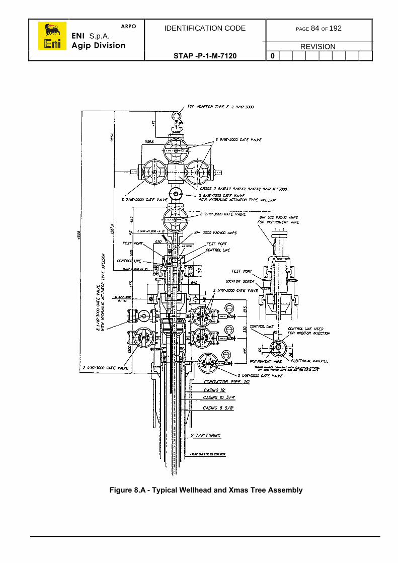
ARPO
ENI S.p.A.Agip Division
IDENTIFICATION CODE PAGE 84 OF 192
REVISIONSTAP -P-1-M-7120 0
Figure 8.A - Typical Wellhead and Xmas Tree Assembly
ARPO
ENI S.p.A.Agip Division
IDENTIFICATION CODE PAGE 85 OF 192
REVISIONSTAP-P-1-7120 0
9. GAS LIFT INSTALLATION
As nearly all gas lift designs use Side Pocket Mandrels (SPM) for gas lift valve installation,the procedures in this section are concentrated on this basis and ignores earlier lesseffective methods (Refer to figure 9.a).
The gas lift method and applications are thoroughly described in the Completion designManual.
9.1. MANDREL INSTALLATION
On production of the gas lift design, the depths of the mandrels will be specified in the wellprogramme. It is essential to have them accurately positioned in the string (to within thenearest joint connection) for optimum well performance providing the gas lift design isbased on accurate well parameters and well data.
The side pocket mandrel may be installed during the initial completion or during a re-completion sometime later. Once the mandrels have been installed, the valves can be runand installed on wireline at any time it is desired to place the well on gas lift.
9.1.1. SPM Installation Procedure
Make up the mandrel sub-assemblies as described earlier in section 8.1. The sub-assemblies should be checked and drifted before installation and generally are run withdummy valves installed in order that the completion string can be pressure tested from boththe tubing and annulus sides. The dummy valves are left in situ until the well is placed ongas lift when the dummies will be replaced with gas lift valves.
The gas lift valves installed on all upper SPMs above the operating point are termed‘unloading valves’ and their function is to allow unloading of the annulus from completionfluid to gas lift gas. The valve installed at the operating depth is the ‘operating valve’through which the gas is injected into the tubing.
Ensure the SPM depths are stated in the well programme. it will be noted that the SPMspacing is closer towards the bottom becoming wider towards the top of the hole.
The installation procedure for the SPMs is as follows:
1) When running the tubing, on reaching the tubing connection nearest the depth atwhich the lowest SPM should be installed, pick up the first mandrel according to therunning list. Do not use pup joints to place the mandrel exactly on depth as the designis not accurate to that degree.
2) Install the mandrel onto the string and continue running tubing.
3) On reaching the connection closest for the second mandrel, repeat step 2.
4) Repeat until all mandrels are installed.
5) Continue with the Completion Programme.
ARPO
ENI S.p.A.Agip Division
IDENTIFICATION CODE PAGE 86 OF 192
REVISIONSTAP -P-1-M-7120 0
Figure 9.A - Typical Side Pocket Mandrel
LatchPacking
CasingPressure
Packing
TubingPressure
Retrievable Mandrel(pressure valve shown)
ARPO
ENI S.p.A.Agip Division
IDENTIFICATION CODE PAGE 87 OF 192
REVISIONSTAP -P-1-M-7120 0
9.1.2. Gas Lift Valve Installation Procedure
As previously stated, the upper gas lift valves are unloading valves and only the lower valveis the gas lift operating valve. The sequence of installation is not important but it is normalpractice to install the valves from the bottom to the top.
A good practice is to install a gas lift valve catcher in the bottom of the tubing below thelower SPM to catch valves which may be accidentally dropped during the wirelineoperations. The catcher is usually a lock mandrel set into a landing nipple with a long sumpon it which will accommodate two valves. If a valve is dropped, operations can continue untila second valve is dropped requiring the catcher to be pulled to retrieve the dropped valves.
If a catcher is not used the valves would probably be lost into the rat hole.
The installation running tool termed, a ‘kick-over’ tool, sometimes is furbished with a catcherbelow on the bottom of the tool but even then it is still good practice to install a catcher subas contingency.
The calibration/setting of the unloading valves and operating valve is normally carried out inthe workshop before shipment to the well site due to the equipment complexity. The valveswill be set in accordance to the gas lift design. Extra valves are usually supplied ascontingency for dropping or damage during transporting and operations.
The wireline procedures for a gas lift valve installation and retrieval are fully described in the‘Wireline Procedures Manual’ (Refer to figure 9.a). Normally the procedure is:
1) Rig up W/L according to the ‘Wireline Procedures Manual’.
2) Install the gas lift valve catcher sub.
3) Install the kickover tool with the appropriate dummy valve pulling tool.
4) If possible, ensure the pressure across the SPM is equalised before step 5 below.
5) Run in the well, locating the lowermost SPM and pull the dummy valve. The tubingand annulus will now be in communication.
6) Pull out of the hole and retrieve the valve.
7) Pick up and install the operating gas lift in the lubricator, run in the hole and install it inthe lower SPM.
8) Pressure up on the tubing to check the valve is correctly located. Do not pressure upon the annulus as the valve allows circulation annulus to tubing.
9) Repeat the procedure in sequence bottom to top for all the other unloading valves.
10) Retrieve the catcher sub.
11) Rig down wireline.
12) Check the operation of all of the surface gas lift system.
13) Unload the well in accordance to the well specific programme.

ARPO
ENI S.p.A.Agip Division
IDENTIFICATION CODE PAGE 88 OF 192
REVISIONSTAP -P-1-M-7120 0
9.2. UNLOADING PROCEDURE
Gas lift installations can be damaged in the first hour or two of unloading by uninformed orimpatient operators. All of the liquid above the top valve must go through the top valveduring unloading. The gas pressure must be increased slowly during the U-tubing processto prevent high differential pressure across the top valve. Desirably, this differentialpressure should be kept less than 100psi.
The following guidelines are recommended for kicking off a continuous flow installation.
1) Remove the choke from the choke tee on the production side of the Xmas tree.
2) Make sure all valves between the well and separator are open.
3) Start injecting gas slowly so the gas pressure increase at the rate of 5psi/min until thegas pressure is 300psi greater than the production pressure at the wellhead
4) Increase the gas injection rate so the pressure increases by 10psi/min until gas iscirculated through the top valve.
5) Adjust the choke on the injection gas for the desired unloading rate.
6) Continue the unloading process for all the other valves until reaching the operatingvalve.
7) After the well is unloaded, adjust the choke on the injection gas to meet with thedesired production rate through the operating valve.
Record and monitor all production and gas injection data including pressures to enablecomparison of the well performance versus the design. If production is not as expected,conduct a fault finding exercise.
The gas lift design can be optimised by making adjustments to the injection rates, pressuresor changing the operating valve settings (by changing out the existing valve). Complexsoftware programmes are available to optimise gas lift production.
9.3. TROUBLESHOOTING
Gas lift installations are designed to unload and operate with a minimum amount of manualcontrol. Constant observation of the well’s performance is necessary to maintain maximumproduction. These observations include well tests, casing-tubing pressures, gas inputvolumes, flowing pressure-temperature surveys, acoustical surveys, static bottomholepressures and producing characteristics.
Should an installation fail to function satisfactorily, it should be analysed carefully beforechanging gas lift valves. Most problems can be determined while the well is still gas liftingMany problems can be corrected or minimised at the surface by changing the surfaceparameters. Should it be necessary to pull valves, the new installation should be based onthe analysis of the previous installations.
Well test data, flowing parameters are most commonly tools used for gas lift analysis. Atwo pen pressure recorder should be used every time a well is unloaded.
ARPO
ENI S.p.A.Agip Division
IDENTIFICATION CODE PAGE 89 OF 192
REVISIONSTAP-P-1-7120 0
10. DOWNHOLE PUMP INSTALLATION
This section contains generic procedures for downhole pump installations, namely ESP,Rod Pumps and Hydraulic Pumps.
10.1. ELECTRICAL SUBMERSIBLE PUMPS
There are a number of different applications and ESP installations which are fully describedin the Completions Design Manual.
This section provides recommended practice on the handling, installation and operation of ageneric ESP system. Because both safety and economic run life are dependent on correctprocedures, the importance of following the recommended practices cannot beoveremphasised.
10.1.1. Handling
The downhole components, motor, pump, protector, and intake are usually shipped in ametal shipping box for protection. The shipping boxes are painted red on the end thatshould be placed towards the wellhead when the equipment is delivered to the wellsite. Theshipping boxes should be lifted with a spreader chain or bridled with a sling at each end.Severe equipment damage can result from dropping, dragging, or bouncing the boxes. Theshipping boxes should never be lifted by the centre of the box only.
The cable reel should be lifted by using an axle and a spreader bar. If a fork lift is used, theforks should be long enough to support both reel rims when the reel is picked up from anend. The ends of the cable should be covered or sealed to protect them from the elements.
Transformers and switchboards are provided with lifting hooks. To avoid damage, therecommended practice is to lift with a spreader bar to maintain a vertical position. Variable-speed drives are normally skid-mounted with fork lift slots and lifting eyes. Some VSDmodels are manufactured with pull bars.
Additional information on ESP handling and installation procedures is available in ‘APIRecommended Practices for Electric Submersible Pump Installation’.
10.1.2. Installation
There are five phases to every ESP installation. These are:
• Well preparation• Site layout• Equipment preparation• Assembly and installation• Start up of the equipment.
The well-preparation procedure involves determining the downhole clearance conditions.Site layout prescribes equipment and rig locations as well as size and capacity. Runningequipment in the well and start-up procedures define the steps in equipment handling, testprocedures, and responsibility of the rig crew and servicemen.
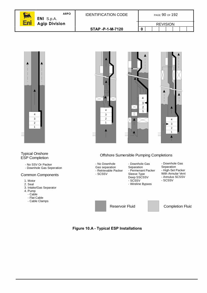
ARPO
ENI S.p.A.Agip Division
IDENTIFICATION CODE PAGE 90 OF 192
REVISIONSTAP -P-1-M-7120 0
Figure 10.A - Typical ESP Installations
4
4
43
3
32
2
21
1
1
123
4
Typical Onshore ESP Completion
- No SSV Or Packer- Downhole Gas Seperation
Common Components
1. Motor2. Seal3. Intake/Gas Separator4. Pump - Cable - Flat Cable - Cable Clamps
Offshore Sumersible Pumping Completions
- No DownholeGas separation- Retrievable Packer- SCSSV
- Downhole GasSeparation- Permenant PackerSleeve TypeDeep SSCSSV- SCSSV- Wireline Bypass
- Downhole GasSeparation- High-Set PackerWith Annular Vent- Annulus SCSSV- SCSSV
Reservoir Fluid Completion Fluid
ARPO
ENI S.p.A.Agip Division
IDENTIFICATION CODE PAGE 91 OF 192
REVISIONSTAP -P-1-M-7120 0
Well Preparation
1) Prior to beginning installation of the ESP equipment, the well must be cleared of anytubing, rods, packers, etc., that would prevent the downhole equipment from reachingtarget depth.
2) The casing flange and wellhead should be examined for burrs and sharp edges. Thisis very important in small-diameter casing because cable damage can be caused byburrs and sharp edges catching cable bands.
3) A gauge ring should be run in (particularly in 4.5” casing) to below the setting depth ofthe downhole equipment. If gauging indicates tight spots, a scraper or reamer runshould be conducted to remove the obstruction (scale, paraffin, burrs, or partiallycollapsed casing). This will ensure adequate clearance for the ESP downholeequipment as it is run into the well.
4) The BOP, if used, should be checked for adequate clearance as well as burrs andsharp edges. Cut-out profiled rams are available for most tubing and cable sizes.They should be installed in the BOP for well control in the event of a kick duringequipment installation.
Site Layout
1) The pulling rig should be centred over the well as close as possible. The guidewheel/cable sheave should be secured safely to the rig mast no higher than 30 to 45ftabove the wellhead. The guide wheel should be at least 54” in diameter.
2) The cable reel or spooling truck should be positioned about 100ft from the wellhead indirect line of sight of the rig operator or driller. One person should be responsible forthe cable operation. The responsibilities of this person are to ensure that there isminimum tension on the cable (the cable should be run at the same speed as thetubing), that the cable is kept clear of the power tongs during tubing makeup or break,and that no one stands in front of the cable reel/spooler.
3) The cable junction box must be located at least 15ft from the wellhead. Theswitchboard must be located a minimum of 50ft from the wellhead and 35ft min fromthe junction box. The junction box normally is located 2 to 4ft above ground level toensure there is adequate air circulation and easy access. The junction box must neverbe located inside a building.
Equipment Preparation
The ESP manufacturer’s field representative must thoroughly check all equipment beforeinstallation.
During installation his responsibility is to supervise the pulling and/or running of thedownhole equipment. All equipment delivered to the wellsite is checked to determine that allcomponents necessary to complete the installation have arrived and are not damaged. TheESP manufacturer’s field representative will perform the following checks and procedures.
1) Remove the shipping box covers and record all component serial numbers from nameplates
2) Check the casing, wellhead and pack-off materials.
3) Check the switchboard for proper fuses, potential transformer set-up, and currenttransformer ratios.
ARPO
ENI S.p.A.Agip Division
IDENTIFICATION CODE PAGE 92 OF 192
REVISIONSTAP -P-1-M-7120 0
1) Check all couplings for shaft diameter and spline match. Check that the shaft iscentred correctly (as impact can cause misalignment).
2) Check the flat cable length, size, and pothead type.
3) Check power transformers for correct primary and secondary voltage rating
4) Confirm that the pump design setting depth and capacity match the well conditionsand the specification in the Completion Programme.
5) Check the power cable and flat cable with instruments and a high voltage megger.
Assembly And Installation Procedures
Once the equipment, cable, and verification procedures are completed, the assembly andinstallation of the downhole equipment can begin. The manufacturer’s field representativemust direct the assembly and check the equipment as it is being run-in. The steps ofassembly and checks of equipment can be summarised as follows
1) Assemble the motor, protector, intake, and pump.
2) Fill the motor/protector assembly with motor oil.
3) Mechanically check the free rotation of downhole components.
4) Check the electrical connection and test the motor, power cable, and flat cablepothead.
5) Check the torque of connecting bolts is correct (use spring washers to prevent loosingof the bolts).
6) Run the pump in the hole installing all the various completion assemblies.
7) Terminate the cable to any pre-made up pigtails through packers, etc.
8) Clamp the cable to tubing string with protectors.
9) Splice the cable or repair any damaged cable.
10) Test the cable continuity and isolation at various depths as it is being run.
11) Terminate the cable to the hanger pigtail.
12) Land the hanger, test the cable integrity and complete the other completionoperations.
13) Connect the power cable to junction box and switchboard.
14) Complete the flowline connections.
15) Once the run-in procedures are completed and final electrical tests completed, themanufacturer’s representative will complete the electrical connections.
16) The switchboard settings will be performed and verified by the manufacturer’sspecialist according to the conditions expected for each well.
17) Phase rotation should be checked carefully to ensure that the pump will rotate in thecorrect direction. Start the pump. Fluid pump-up time, load and no-load voltage andamperage on each phase must be recorded.
18) Monitor the wellhead pressure while the string is still full of completion fluid to verifycorrect pump operation.
19) The quantity of production oil, gas, and water should be monitored on start up andregularly for the time required to achieve stability.
A careful study should be made on any pump installation that does not produce at thedesigned rates. As much information as possible should be gathered to aid in specificidentification of problems and appropriate remedial actions. This will help ensure thatsubsequent ESP installations will provide satisfactory run life.
ARPO
ENI S.p.A.Agip Division
IDENTIFICATION CODE PAGE 93 OF 192
REVISIONSTAP -P-1-M-7120 0
10.1.3. Pulling Procedure
Pulling the equipment out of a well involves essentially the reverse process of theinstallation procedure.
If the equipment failure is judged to be premature, the condition of cable, flat cable, pumprotation, and motor/protector fluid will be useful in determining the cause of the failure.
10.1.4. Troubleshooting
This section outlines a recommendations to identify typical ESP problems and providesolutions. The sole method that a failure can be analysed and its cause determined, is bydata collection. When problems occur, obtaining as much data as possible is essential.
Data Collection
Information that should be routinely compiled on each ESP installation includes:
• Production data (such as water, oil, and gas rates)• Run life in days• Number of unit start ups and stoppages• Dynamic and static fluid levels• Pump setting depth• Perforation depths.
Information also should be obtained on:
• Ammeter charts• Well conditions (abrasives, corrosives, H2S, etc.)• Electric power quality (surges, sags, balance, negative sequence voltages, etc.)• Visual observations of equipment and cable condition on prior workovers• Reasons for equipment workover (failure, workover, size change, etc.)• BHT recordings
When an ESP well is first placed on production, data should be collected daily for the firstweek, weekly for the first month, and a minimum of monthly after the first month. Productiondata during the first month are very important because they will indicate whether the pumpis performing as designed. If a downhole pressure instrument is installed, operating BHP isequally if not more important.
The major source of information when troubleshooting an ESP installation is the recordingammeter. The recording ammeter is a circular strip-chart accessory mounted in theswitchboard that records the amperage drawn by the ESP motor. A number of changes inoperating conditions can be diagnosed by interpreting ammeter records. The followingaddresses ammeter chart ‘reading’ and typical problem situations.
ARPO
ENI S.p.A.Agip Division
IDENTIFICATION CODE PAGE 94 OF 192
REVISIONSTAP -P-1-M-7120 0
Normal Operation
A normal chart is smooth, with amperage at, or near to the motor specification amperagedraw. Actual operation may be, either, slightly above or below the specification amperage,however, as long as the curve is symmetric and consistent over a period of time, operationis considered normal.
Normal Start-up
The start-up ‘spike’ is caused by the inrush surge as the pump comes up to operatingspeed. The subsequent amperage draw is high but trending towards the normal level. Thisis principally a result of the fluid level being drawn down to the design TDH, resulting in ahigh but declining amperage draw. Using the modern variable speed units this problem hasbeen overcome.
Power Fluctuations
Operating ESP amperage will vary inversely with voltage. If system voltage fluctuates, theESP amperage will fluctuate inversely to maintain a constant load. The most commoncause of this type of fluctuation is a periodic heavy load on the primary power system. Thisload usually occurs when starting up another ESP or other large electric motor.
Simultaneous start-up of several motors should be avoided to minimise the impact on theprimary power system.
Ammeter spikes also can occur during a thunderstorm that is accompanied by lightningstrikes.
Gas Locking
Gas locking occurs as fluid level drawdown approaches the pump intake and intakepressure is lower than the bubble-point. There are three possible remedies for gas locking:
• Install a gas intake and/or a motor shroud• Lower the setting depth of the pump (but not lower than the perforation unless
the motor is shrouded)• Reduce the production rate of the pump by using a surface choke (but ensure
that the production rate remains within the recommended range for that pump).
It is entirely feasible that none of these solutions is satisfactory, then the pump should bereplaced with a pump that does not draw down the fluid level or reduce intake pressurebelow the bubble-point.
Another possible solution is to add a variable speed drive (VSD) to the existing system. TheVSD controls the speed of the pump, which in turn controls the pump capacity. Thus thepump output can be fine-tuned to protect against pump-off and gas lock while contributingto improved pump life.
If the problem is confirmed to be due to reservoir conditions, then a stimulation operationmay be considered to reinstate the original PI and therefore allow operation of the currentESP design.
ARPO
ENI S.p.A.Agip Division
IDENTIFICATION CODE PAGE 95 OF 192
REVISIONSTAP -P-1-M-7120 0
Fluid Pump-Off
Fluid pump-off occurs typically when an ESP is too large in relation to the inflow capacity ofthe well. The remedial actions are much the same as those listed for a gas lock and, inaddition, a well simulation treatment may increase the well’s productivity closer to a matchwith the pump.
In general, cycling an ESP will have an adverse effect on optimal run life. As a temporarymeasure, the amount of time delay before automatic restart can be increased if theswitchboard is equipped with a Redalert Motor Controller. This may allow the fluid volume tobuild up to prevent a high frequency of shutdown occurrence. Nevertheless, the pump andwell are not compatible and the pump size should be checked on the next change-out or thewell worked over to improve productivity.
Gassy Conditions Or Emulsion
Continuos amperage fluctuation results from alternating free gas and heavy fluid pumping.Generally this condition results in a reduction of stock tank barrels in relation to the pumpdesign rate.
This is also typical of emulsion conditions. The fluctuations are caused by the frequent,temporary blockage of the pump intake. If it is an emulsion block, spikes are normally loweror below the normal amperage line.
Solids and Debris
When solids or debris are produced in a well, the amperage will display fluctuationsimmediately after start-up. Typically, when solids such as sand, scale, or weighted mud areproduced, special care must be taken on start-up to avoid pump damage. It may benecessary to apply back-pressure on the well to prevent excess amperage until the kill fluidis removed and/or sand production begins to decline to a safe volume.
Overload Shutdown
A pump will automatically shut down when it reaches an overload condition. When anoverload condition shutdown does occur the unit must not be restarted until the cause ofthe overload has been identified and corrected. Some motor controller overload-detectioncircuits contain a built-in time delay, ranging from 1 to 5 secs at 500% of the set point to 2 to30 secs at 200% of the set point. However, they will not automatically restart the unit on anoverload condition. A restart attempt in an overload condition can destroy the downholeequipment if the cause of the overload is not identified and corrected first.
The most common causes of overload conditions are:
• Fluid pump-off• Increased fluid specific gravity• Sand production• Emulsion formation• Scale• Electric power supply problems• Worn equipment• Lightning damage
Many of the problems outlined above have been reduced due to the use of VSD.
ARPO
ENI S.p.A.Agip Division
IDENTIFICATION CODE PAGE 96 OF 192
REVISIONSTAP -P-1-M-7120 0
10.2. ROD PUMPS
There are two separate phases to a rod pump completion, the installation of the completiontubing string and the installation of the rod pump and power mover.
10.2.1. Completion Installation
There are two common types of completion string configurations which are described in the‘Completion Design Manual’. The first is when the tubing is simply suspended in the wellfrom a tubing hanger and the other is run with a tubing anchor to anchor the bottom end ofthe tubing string.
A tubing anchor counters tubing movement caused by the reciprocation of the rods andpump plunger within the tubing and pump barrel saving wear and tear.
There are also two types of pumps designs, where the barrel is installed, either, in thetubing (tubing installed pump) or run in on the sucker rods (rod installed pump). (Refer tofigure 10.b).
The installation procedures for both options are described below.
10.2.2. Tubing String Installation
The well specific and pump manufacturer’s installation procedures should be provided in thewell programme.
1) Prepare the hole for the completion by conducting any stimulation operations andensuring the well completion fluid is clean and in proper condition (Refer to section4.2).
2) Prepare the rig for running the completion string.
3) Ensure all the completion assemblies have been pressure tested, function tested anddrifted.
4) Ensure the tubing has been properly cleaned and drifted and the connectionsinspected for damage. Prepare the tubing for running as per section 7.3.2.
5) Pick up the tubing anchor and tubing anchor assemblies, whichever is applicable, andplace in the rotary table setting the slips with a dog collar.
6) Pick up and make up the pump barrel assembly or the pump barrel landing nippleassembly (if the pump barrel is installed on the rods).
7) Pick up the first joint of tubing, make up to the barrel, or barrel nipple, and beginrunning in the hole.
8) Continue running tubing until reaching the design depth.
9) Attach the tubing hanger and landing joint. If the tubing is to be placed in tension toprevent tubing movement, run to the calculated depth which will apply the correcttension, set the tubing anchor, pull the tubing into tension and set the tubing hanger. Ifthe tubing is to be set in neutral, land off the hanger then set the tubing anchor.
10) Pressure test the tubing hanger.
11) Rig up wireline and make a drift run with a gauge cutter.
12) Run and install the standing valve.
13) Rig up the test head and pressure test the valve and tubing to the pressure specifiedin the well programme.
14) Rig down wireline.

ARPO
ENI S.p.A.Agip Division
IDENTIFICATION CODE PAGE 97 OF 192
REVISIONSTAP -P-1-M-7120 0
Figure 10.B - Types of Bottom Hole Rod Pumps
Plunger
Travelling Valve
Working Barrel
Sucker Rods
Tubing
WorkingBarrel
(Heavy Wall)
Standing Valve
Shoe
Tubing Pump Rod Pump
ARPO
ENI S.p.A.Agip Division
IDENTIFICATION CODE PAGE 98 OF 192
REVISIONSTAP -P-1-M-7120 0
10.2.3. Rod Installation
1) Prepare the rig for running the sucker rods.
2) Ensure that the rods and pump assemblies have been properly checked and tested.
3) Pick up the pump plunger (with or without the pump barrel) and set in the rotary table.
4) Pick up the first sucker rod and make up to the pump plunger.
5) Run the plunger in the hole on the rods.
6) When near the barrel or barrel landing nipple, run very slowly in the hole and tag thebarrel confirming the depth correlates correctly.
7) Pull back to space out the rods so that the polished rod will be positioned correctlythrough the stuffing box.
8) Attached the polished rods and stuffing box.
9) Make up the stuffing box to the wellhead and pressure test through the flowlineagainst the standing valve.
10) Suspend the polished rod and move the rig off the well.
11) Clear the area to allow the prime mover to be positioned.
12) Bring in the prime mover, locate and check the position of the horse head over thewell centre. Bolt down the prime mover.
13) Conduct tests on the mover to ensure its correct operation prior to connection to thepolished rods.
14) Attach the bridle and carrier bar to the polished rod and adjust to the correctheight/stroke position.
15) Connect up the flowline to the production facility.
16) Connect the annulus gas outlet line into the flowline.
17) Pressure test according to the programme.
18) Begin the pump commissioning process bringing the well onstream.
19) Monitor that the initial produced fluid volumes is as per the design.
20) Collect data of production and prime mover current consumption.
21) Optimise the pump speed to maximise stable production flowing conditions.
10.3. HYDRAULIC PUMPS
There are three main types of hydraulic pump installations, jet pump, turbine pump and thepiston pump.
The applications and installation methods for each of these is fully described in the‘Completion Design Manual’. The installation procedures are addressed below.
ARPO
ENI S.p.A.Agip Division
IDENTIFICATION CODE PAGE 99 OF 192
REVISIONSTAP -P-1-M-7120 0
10.3.1. Jet Pump
Jet pumps are usually installed in a ported receptacle such as a wireline ported landingnipple or a sliding side door as communication between the tubing and annulus isnecessary to provide a flow path for the power fluid.
A completion in not usually specifically designed for jet pump lift but is designed for bothnatural flow and with the jet pump ported landing nipple or SSD installed for contingencyduring later well life. The flow areas of the completion, however, also need to be consideredin the design stage for the efficiency of the pump design.
Jet pump designs include the use of the annulus or a second tubing string to deliver thepower fluid to the pump. If a second tubing string was to be employed, the well would needto be re-completed as a dual or concentric completion.
A pump design will have been produced specifying the pump nozzle size, power fluidpressure and volume requirements, and production target. The major work to convert to jetpump is in the provision and recycling of the power fluid which will require additionalpumping facilities in conjunction with separation equipment to recover the power fluid.
1) Install all surface jet pump facilities, make connection to the annulus, function andpressure test, and commission.
2) Rig up wireline on the well according to the procedures in the ‘Wireline Proceduresmanual’.
3) Install the required shifting tool to open the SSD or expose the port in a ported landingnipple. Check for communication by pumping on the annulus or tubing.
4) Pull out of the hole.
5) Install the jet pump having ensured it is correctly set up and attached to the properlock mandrel. Run in the hole and set it in the receptacle.
6) Pull out of the hole and rig down wireline.
7) Begin pumping slowly gradually increasing the rate, monitoring and measuring powerfluid returns and production rates.
8) Gather all pump and production data and analyse the data to ensure the pumpsystem is performing within the design parameters.
9) Optimise pump performance by tuning the injection pressure to obtain the highestpossible stable flowing production. This may involve retrieval of the jet pump andchanging the nozzle size.
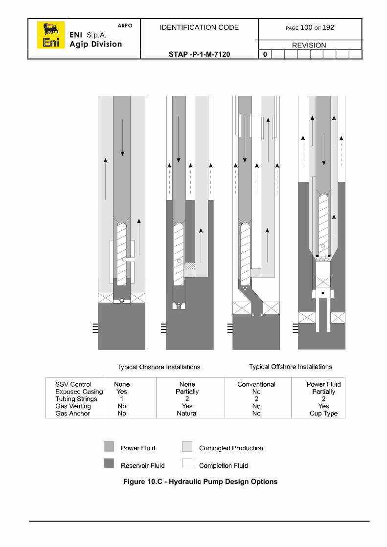
ARPO
ENI S.p.A.Agip Division
IDENTIFICATION CODE PAGE 100 OF 192
REVISIONSTAP -P-1-M-7120 0
Figure 10.C - Hydraulic Pump Design Options
ARPO
ENI S.p.A.Agip Division
IDENTIFICATION CODE PAGE 101 OF 192
REVISIONSTAP -P-1-M-7120 0
10.3.2. Turbine Pump
The surface facilities described for the jet pump apply to the turbine pump also. Howeverthe installation of the downhole turbine pump usually requires re-completion of the well asthe pump is tubing installed and retrieved.
As the turbine pump is capable of pumping much higher volumes than the jet pump, theflow path area is more critical to pump capacity and efficiency.
The completion design options, could require a second flow conduit (Refer to figure 10.c).
10.3.3. Piston Pump
The piston pump completion procedure is exactly like that of the jet pump except that apositive piston pump is installed into the ported receptacle.
The procedure for installation of the pump and commissioning is the same as the jet pump.Scheduled maintenance change-outs of the pump should be planned as the pump design ismore complex than the jet pump and more susceptible to wear and tear.

ARPO
ENI S.p.A.Agip Division
IDENTIFICATION CODE PAGE 102 OF 192
REVISIONSTAP-P-1-7120 0
11. SUBSEA COMPLETIONS
The design and installation procedures for subsea wells is significantly different from landand platform wells. Although the downhole completion equipment is generally the same, thesubsea wellhead and subsea Xmas tree systems are totally different and are alsomanufacturer specific.
Similarly, well interventions methods from floating vessels are much more complex requiringspecialised well intervention or workover systems.
In today’s technology, there are two main types of subsea Xmas tree and interventionsystems termed ‘Conventional’ and ‘Horizontal’.
The conventional subsea completion system utilises a Xmas tree with valving configurationssimilar to dual surface Xmas trees, to which a dedicated well intervention riser, run from thevessel, can be attached. After latching to the subsea Xmas tree and testing the integrity ofthe system, well servicing operations such as wireline and coiled tubing can be safelyconducted through the riser into the wellbore. This riser system is also utilised for theinstallation and retrieval of the subsea tree.
This design, however, has some drawbacks in that the dedicated riser systems areextremely costly to purchase and maintain, especially for fields with only a few wells overwhich to share the costs. Nowadays, some standardisation has been adopted betweenmanufacturers and riser systems which are adaptable to various manufacturers subseatrees are offered on a rental basis, however their availability at critical times may not alwaysbe guaranteed. Further to this, in order to re-complete or workover a well, the conventionalsystem requires the subsea tree to be recovered and a marine riser system deployed to beable to pull the completion string.
A less costly alternative to the conventional subsea tree system, is the ‘Horizontal’(sometimes refereed to as ‘Spool’) system. This only requires the use a conventional drillingmarine BOP riser system for re-completion or workover. Tie-back strings and tooling back tosurface are deployed through the riser to enable access to the tubing bores. The horizontalsystem design uses a casing head spool through which casing and the completion stringcan be installed (with the tree production valves equivalent to two master valves on thehorizontal flowline bore). This enables re-completion or workover operations to beconducted without having to pull the subsea tree and without having to purchase adedicated riser system. The drawback of these systems is the complexity of the re-entrytools used inside the marine riser for wellbore re-entry (dual subsea tree, tubing runningtool, etc.).
Note: As subsea completion systems designs and procedures are specific tothe project/manufacturer, the conventional Cooper system is described inthis section which was used on the Eni-Agip UK Toni Field which is typicalexample of a subsea completion system.
ARPO
ENI S.p.A.Agip Division
IDENTIFICATION CODE PAGE 103 OF 192
REVISIONSTAP -P-1-M-7120 0
11.1. SUBSEA EQUIPMENT PRE-DEPLOYMENT TESTING
Refer to specific field downhole, and subsea completion equipment, contained in thecompletion programme. The pre-deployment procedures given in this section are intendedto be generic, however some designations or abbreviations used may tend to reflect theEni-Agip UK Toni development which was the first development on the T-block.
11.1.1. Guidewire Establishment Tool
Guidewires can be run and attached to the guideposts separately by lowering the latchesattached with a suitable clump weight and having a diver or ROV aligning them to eachpost, in turn. The alternative method is to use a guidewire establishment tool. This tool issimply a frame deployed on drill pipe which correctly spaces out the latches and attaches allfour guidewires at once after a diver or ROV has aligned the frame.
• The tool should be checked to ensure it has not been damaged and is intact.• Check that the connectors fit the tool.• Check the lower/pulling pad eyes and shackles, etc.
An alternative guidewire running tool for use in deep water, combines a camera and guideframe deployed on drillpipe which is steered by fluid jets. Pumping down the drillpipe steersthe tool via the jetting nozzles, and the camera allows the observation of the positioning andorientation of the collet connector above the guide post. One draw back of this tool is theability to run only one guideline connector at a time.
The tool should be checked to ensure that it has not been damaged and is intact.• Check that the connectors fit the tool.• Check the nozzles operate correctly.• Attach the camera umbilical and ensure the camera is operational.
11.1.2. Guidewire Latchess
Ensure that the collet latches are in good serviceable condition and that the guidewireshave been correctly attached. Ensure that contingency attachment and retrieval proceduresare available in the event a post is damaged, unless retrievable guideposts are installed(Refer to section 11.1.3).
11.1.3. Diverless Guideposts
Diverless guideposts are run and installed in the permanent guidebase or productionguidebase and should be check prior to running.
• Check the latching mechanisms or post retainer pins to observe that they arefully operational (by ROV).
• Check the latching profiles on the posts to ensure they are not corroded ordamaged.
ARPO
ENI S.p.A.Agip Division
IDENTIFICATION CODE PAGE 104 OF 192
REVISIONSTAP -P-1-M-7120 0
11.1.4. Casing Hanger Elevation Test Tool
Some systems have an elevation test tool to check the casing hanger has been correctlyinstalled. It is run through the drilling riser to check the hanger before committing to pullingthe BOP stack.
The tool usually consists of a locating shoulder and lead impression blocks which whenlanded off and pumped out will establish the vertical position of the hanger in the wellhead,once the impressions are inspected and measured. With this type of tool it is necessary toclose the divertor or a set of pipe rams and pressurise the annulus to 500psi to ensure fullretraction of the impression blocks.
• Ensure the impression block system is operative and set in the retracted runningposition. Check the connection and that any crossovers required, are on hand.
11.1.5. Tubing Hanger System
The tubing hanger assembly consists of the hanger and a pup joint, typically 10ft long, andnecessitates the hanger stand being located over a suitable hole in the deck or drill floor. Atypical configuration of tubing hanger equipment including the running tool, prior to running,is shown in figure 11.a.
The following sequence of pre-deployment testing is typical for a tubing hanger.
1) Locate the tubing hanger stand in a suitable location over a hole on the deck for thepup joint/joints. This location must be within the reach of a crane which can accessthe derrick V-doors.
2) Proceed to set up the seals, inspect and check the tubing hanger as per themanufacturer’s operating manual.
In addition, note the following:• Ensure that anti-rotation pins are fitted.• Check that the hanger bores are clean and undamaged.• Check landing nipple profiles where fitted.• Check that the correct orientation key is fitted, if applicable.• Grease the appropriate parts of the hanger lock-down parts.• Fit the control line tubing connectors to the tubing hanger.• Inspect electrical cable tails where fitted.• There is a considerable risk of causing damage to the tubing hanger nose seal
area when installing or retrieving a hanger in the tubing hanger stand, therefore,the hanger should be installed in the stand a minimum number of times.
3) When preparation of the tubing hanger is complete, leave the tubing hanger in thetubing hanger stand or remove the hanger from the stand and lay back down in itsshipping box. Protect the tubing hanger from mechanical and weather damage.
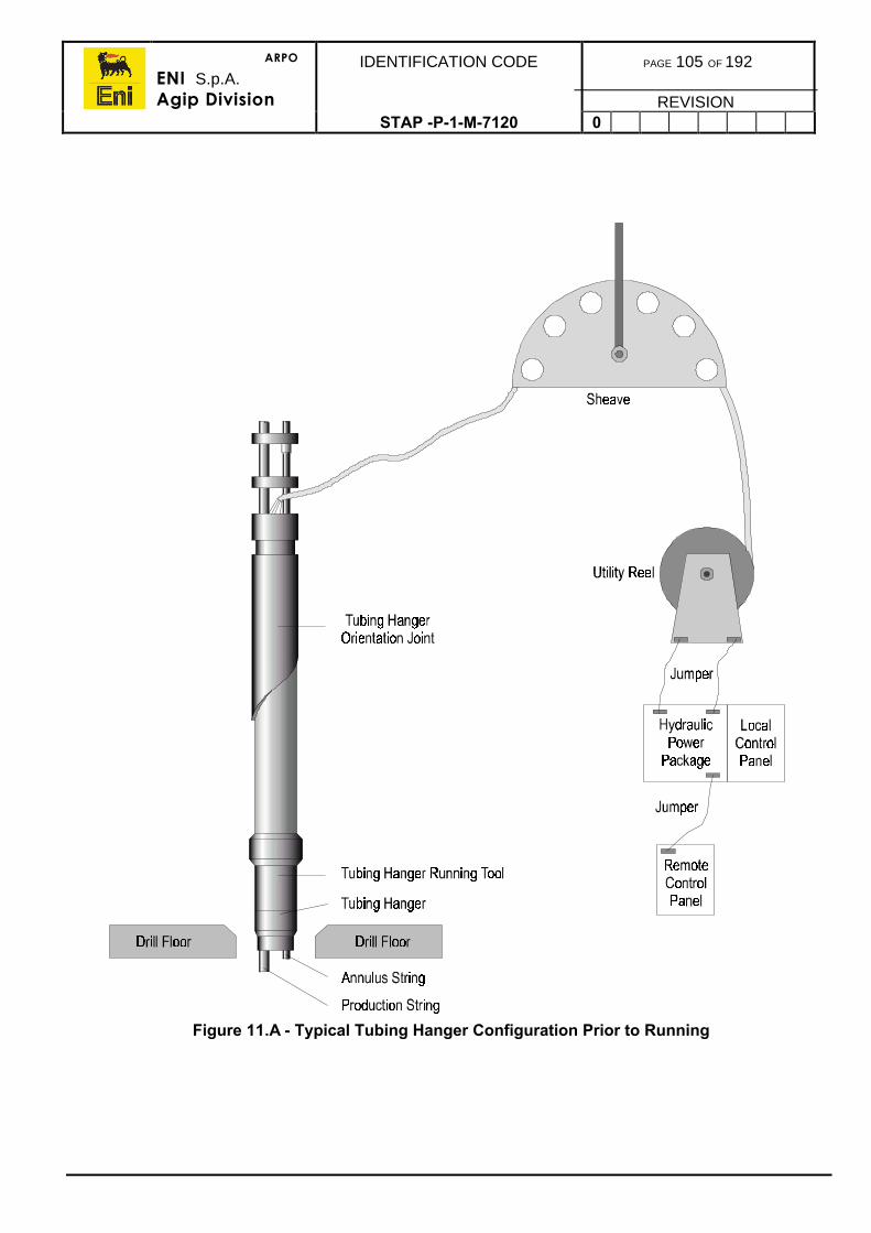
ARPO
ENI S.p.A.Agip Division
IDENTIFICATION CODE PAGE 105 OF 192
REVISIONSTAP -P-1-M-7120 0
Figure 11.A - Typical Tubing Hanger Configuration Prior to Running
ARPO
ENI S.p.A.Agip Division
IDENTIFICATION CODE PAGE 106 OF 192
REVISIONSTAP -P-1-M-7120 0
11.1.6. Tubing Hanger Running/Orientation Tools
This section details the pre-testing of a typical production tubing hanger running tool systemconsisting of the following items of equipment (shown with common abbreviations):
• Tubing Hanger Running Tool, (THRT)• Tubing Hanger Orientation Tool, (THOJ).
Some systems have the THRT and THOJ as separate tools, whilst other systems have asingle run/set and orientation tool.
For setting up of the orientation of the THRT/THOJ refer to the Manufacturer’s OperationsManual.
Pre-deployment testing may be performed, either on the rig deck or drill floor, and involvesstack-up of the THRT on the tubing hanger and utilises the test stands. Tests, according tothe manufacturer’s operating procedures manual, will be required to verify the integrity ofthe system. These will cover the following aspects:
• Cleanliness of the hydraulic systems meets with the specification, especially thesub-surface safety valve line, usually to NAS 1638 class 6 or better.
• Operation of all of the THRT functions.• Pressure integrity and operation of all hydraulic lines from the panel to the
tubing hanger.
The following tests are required to test the integrity of the system. Afterwards the THRT andtubing hanger assembly will remain as one unit stored on the rig floor, connected to theutility umbilical, if possible. A second or back-up system must be available for testing. Thetesting procedure can be modified as long as the overall testing requirements are satisfied:
1) Check the tubing hanger in its shipping box (Refer to previous section).
2) Install the tubing hanger in the tubing hanger stand over a suitable hole in the deck.
3) Position the THRT tool stand.
4) Install the THRT in its stand and test.
5) Interface test and flush the THRT with the tubing hanger in the stand.
6) Check and position the tubing hanger body seal.
7) Check the THOJ and flush through the tool.
8) Move the THRT and stand up to the rig floor.
9) Move the THOJ to the rig floor with the handling tool and make up to THRT.
10) Return the complete assembly to the deck and test.
11) Before running the tubing, return the complete tool to the rig floor.
12) Run through the rotary and make up to enough joints of tubing or 5” DP to stand theassembly back in the derrick.
13) Hook up the utility umbilical.
14) Stand back in the derrick.
15) Test the function lines.
ARPO
ENI S.p.A.Agip Division
IDENTIFICATION CODE PAGE 107 OF 192
REVISIONSTAP -P-1-M-7120 0
These activities are described in more detail in the following sections. Refer to the specificmanufacturer’s Operation and Maintenance Manual for additional instructions.
It should be noted that pressure tests conducted through flexible hoses will be subject tosome pressure decay caused by umbilical expansion. For this reason, an acceptablepressure decay should be established during chart recorded tests.
All site received inspections and ECR punch list items relating to this equipment must havebeen satisfactorily addressed before proceeding.
THRT Preparation
1) Locate the THRT stand adjacent to the tubing hanger stand on the rig deck and withinhot-line range of the control panel.
2) Perform THRT preparation according to the Manufacturer’s Operating Manual.
3) Perform LATCH/UNLATCH and LOCK/UNLOCK tests.
4) Check the orientation key function and that the correct key is selected to ensurecorrect orientation of the hanger.
5) Install the running tool back onto the stand.
Interface THRT with the Tubing Hanger
1) If not already done, install the tubing hanger in it’s stand. Ensure that all seal pocketsare clean and lubricated with control fluid. Install a connector (or dummy) into the topof the downhole pressure transducer bore, if not already fitted, to enable a peripheraltest to be conducted and the connector to be tested. (Beware of damaging any noseseal components against the tubing hanger stand).
2) Using hotlines connected to the THRT, proceed to remove the tool from it’s stand andinterface it with the tubing hanger according to the operating procedures. The tubinghanger must be in the locked position prior to this activity.
3) The TH/THRT interface should now be tested (by chart or gauge) in order to verify theinterface and all functions.
4) Additionally, all TH lines must be flushed to the correct cleanliness specification.
5) Fill the TH/THRT cavity.
6) Proceed to function and pressure test.
7) Pump control fluid through the sub-surface safety valve line and injection lines tocheck continuity. Cap the pre-installed fittings in each bore in the bottom of the tubinghanger and pressure test each line.
8) Unlock the tubing hanger.
9) Disconnect the THRT from the tubing hanger. Pick up and land in the nose protector.Secure and vent all pressure to the THRT.
10) Leave the tubing hanger in it’s stand and remove the electrical connector. Ensure thatthe hanger top face is protected against damage and weather.
ARPO
ENI S.p.A.Agip Division
IDENTIFICATION CODE PAGE 108 OF 192
REVISIONSTAP -P-1-M-7120 0
THOJ Preparation
1) Check end connections and seals when horizontally located on the deck. Check thatthere is no evidence of orientation sleeve and slot damage. Check the orientationsleeve securement pins and field welds for damage or distortion. Check the downholepressure transducer connectors.
2) Fit the flushing tool to the bottom end of the joint, hook up the utility or test umbilical tothe top and circulate/flush as necessary to achieve the required hydraulic cleanliness.
3) Disconnect the utility or test umbilical and cover/protect any quick couplers.
4) Fit the handling tool to the top end of the joint.
Connect THOJ to THRT (if required)
1) The THRT and its nose protector must be moved to a position close to the rotary tableto enable stabbing of the orientation joint.
2) Check all faces, seals and alignment pins and replace as necessary.
3) Check the downhole pressure transducer connector.
4) Pick up the prepared THOJ and pre-fitted handling tool and make up to the THRTchecking all seals and connectors, etc.
5) Pick up the assembly and return to the test area on the deck where access to theutility umbilical is available.
THOJ and THRT Interface Tests
1) Temporarily connect the utility umbilical to the THOJ, securing the umbilicaltermination.
WARNING: Do not bend the umbilical beyond it’s minimum specified bend radius.
2) Function and test all lines.
3) Vent all pressure after the testing.
4) Insert a test plug in each of the lower end stab pockets in turn and pressure test andflush to specification.
5) Check the transducer connections for continuity and resistance from the utility reel tothe lower end of the running tool. If necessary, test the THOJ/THRT interface duringthe electrical test and record on a chart.
6) Recheck all seals at the base of the THRT after testing, replace as necessary andrefit the nose protector.
ARPO
ENI S.p.A.Agip Division
IDENTIFICATION CODE PAGE 109 OF 192
REVISIONSTAP -P-1-M-7120 0
Make Up and Testing the THOJ/THRT
1) Make-up a handling string of tubing joints or 5” drillpipe and lay down on the catwalk.
2) Disconnect the utility umbilical from the THOJ, ensuring minimum contamination to thehydraulic system.
3) Pick up the riser handling tool/THOJ/THRT assembly and move to the rig floor.
4) Make-up the handling string of tubing joints or drillpipe to the riser handling tool.
5) Pick up the assembly, taking extreme care not to damage the electronic/hydraulicquick couplers when pulling out, until the couplers are 3ft above the rotary table.
6) Connect up the utility umbilical. Ensure that hydraulic contamination is minimisedduring hook-up.
WARNING: Do not bend the umbilical beyond it’s minimum specified bend radius.
7) Ensure the umbilical clamps are a tight fit. Ensure that the installed clamp dimensionsare within the BOP diameter.
8) Umbilical tails must be plaited as necessary to take up any excess length and toprovide protection.
9) Protect hoses as much as possible by tying back to the riser pipes.
10) Fit a hose protector if provided.
11) While handling the sheave and paying out the umbilical, stand the assembly back inthe derrick and secure to protect from unnecessary damage.
12) When stood back, the final pressure and function tests of the lines from the panel torunning tool can be performed in order to save time later.
13) The THOJ/THRT assembly is now ready for use.
11.1.7. Tubing Hanger Verification Tool
The tubing hanger verification tool is used to check the positioning of the hanger within thewellhead after being set, with regards to orientation and height. This ensures that thesubsea Xmas tree’s stabs will correctly align with the bores in the hanger thus saving themfrom being damaged if misaligned or if the tubing hanger is set too high.
Note: Some subsea tree designs have extension subs that can be shimmedand/or slide within seal pockets to adjust for any incorrect stack upheights of the casing hanger or tubing hanger assemblies. Typically thisadjustment is limited to a maximum of 1 to 2ins.
Mechanical probes, sleeves, lead impression blocks are all used in various tool designs withsome being diver assist.
• The tool’s probes or shear sleeves must be set and pinned according theManufacturer’s Operating Manual.
• Care should be exercised so as not to accidentally clash with other equipmentand inadvertently move the probes or sleeves thus giving a falseindication/impression.
• If diver assist, the diver must be fully versed in the tool operation.
ARPO
ENI S.p.A.Agip Division
IDENTIFICATION CODE PAGE 110 OF 192
REVISIONSTAP -P-1-M-7120 0
11.1.8. Tubing Hanger Isolation Plugs
The tubing hanger isolation plugs are wireline installed and are described in the specific wellprogramme.
• Profiles should be inspected for any damage.
11.1.9. Subsea Tree And Workover Equipment
This section describes in outline the pre-test activities to be performed on:• Subsea Xmas Tree (XT)• Lower Riser Package (LRP)• Tree Running Tool (TRT) or Emergency Disconnect Package (EDP)• Tree Cap• Tree Cap Running Tool (TCRT).
Preparation of this equipment, up to the end of the main and utility umbilicals, is addressedin the following sections.
After each of the above items is loaded onto the rig, a Site Received Test should have beenperformed. Thereafter, the equipment will be stacked, function and pressure tested on deckto verify equipment performance prior to running.
Assuming that all the necessary equipment is available, SRTs are complete and ECRPunch Lists are acceptable, pre-deployment testing should commence as defined below.
Note: The manufacturer’s Operation and Maintenance manual should befollowed for detailed specific procedures.
Pre-test activities should be performed on deck and conducted according to a plan providedin the well programme.
1) Place the XT on the XT test base and the tree cap on the LRP test base ensuring thatthe connectors are fully unlocked prior to interface and correctly locked followinginterface. Connector indicator pins should be observed to be correctly positioned.
2) Flush the control lines to the specified cleanliness standard.
XT
XT + XTBASE
= XTBASE
TCRTTCRT CAPCAP + LRP BASE = LRP BASE
3) Test the XT/XT base interface, i.e. AX/VX gasket, production, annulus and flowlinebores.
4) Integrate the XT and tree cap ensuring that the connectors are fully unlocked prior tointerface and correctly locked following interface. Connector indicator pins should beobserved to be correctly positioned.
ARPO
ENI S.p.A.Agip Division
IDENTIFICATION CODE PAGE 111 OF 192
REVISIONSTAP -P-1-M-7120 0
1) Test production, annulus bores and peripheral area.
TCRTTCRT CAP
XT + CAP = XTXT BASE XT BASE
7) Flush all XT and cap control lines.
8) Pressure test lines.
9) Assemble the Subsea Control Module (SCM) to the tree assembly ensuring that theconnectors are fully unlocked prior to interface and correctly locked followinginterface. Connector indicator pins should be observed to be correctly positioned.
TCRT TCRTCAP CAP SCM
SCMXT + = XTXT BASE XT BASE
10) Function and test via the Portable Electronic Simulator Unit (PESU):
• DHPTT and sensor readings• Platform PCS commands and shutdown sequences• Hydro-test both sides of actuated valves.
11) If the LRP and TRT control fluids are acceptably clean, stack p as shown and test theinterface ensuring that the connectors are fully unlocked prior to interface andcorrectly locked following interface. Connector indicator pins should be observed to becorrectly positioned.
LRP + LRP + TRT = TRTBASE LRP
LRPBASE
12) Flush all lines. Hook up to Workover Control System (WOCS) and perform:
• Pressure test of bores and AX/VX cavities• Pressure test of control lines at TRT/LRP interface• Hydro-test both sides of LRP valves.
13) Integrate the LRP on the XT assembly ensuring that the connectors are fully unlockedprior to interface and correctly locked following interface. Connector indicator pinsshould be observed to be correctly positioned.
TCRT TRTCAP SCM LRP SCM
- TCRT + TRT =XT CAP LRP XT
XT BASE XT BASE
ARPO
ENI S.p.A.Agip Division
IDENTIFICATION CODE PAGE 112 OF 192
REVISIONSTAP -P-1-M-7120 0
14) Pressure and/or function test through the WOCS:
• LRP AX/VX line, production and annulus bores.• All XT/LRP control lines.• Ensure that any accumulators fitted to the LRP are charged and charging
following functioning of the valves supplied by the accumulator. Theaccumulator vent function (to the sea or to an atmospheric cylinder to improvevalve response times) should be checked on surface.
15) Drift production and annulus bores through entire stack-up.
16) Re-check SCM functions by operating against the LRP.
This completes the XT/SCM/LRP/TRT preparation.
Flushing XT and Tree Cap
1) Prepare the XT for interfacing with the tree test base in accordance with theManufacturer’s Operating Manual.
2) Completely fill the production and annulus flowline hub bores with water.
3) Lift the tree using the handling tool and lock the XT onto the XT test base usinghotlines ensuring that the connectors are fully unlocked prior to interface and correctlylocked following interface. Connector indicator pins should be observed to be correctlypositioned.
4) Flush and sample the lines as necessary. Clean the tree control lines to the specifiedcleanliness to enable the tree and cap to be interfaced.
Note: This step may be omitted if the tree is known to be clean through previousflushing. Hydraulic cleanliness must be verified by sampling 3 lines atrandom within each assembly. All three samples must all meet hydrauliccleanliness criteria.
The combined XT and cap will be flushed together later. This activityshould be conducted with the assistance of a tree schematic which willshow all the lines on the tree.
5) Hotline open the ASV and AMV and drift the tree production bore valves. Close thevalves after drifting. Valve indicator pins where fitted should be observed for correctaction and travel.
6) Pressure test the XT/test stump interfaces through the test skid lines.
7) If required, hook up the DHPTT simulator to the electrical lines emerging from thebase of the tubing hanger simulator and check.
8) Fill the tree and test stump with water to aid later testing when the cap is installed onthe tree by using hotlines to open all necessary valves. Valve indicator pins wherefitted should be observed for correct action and travel.
9) Bleed air from test stump connections as necessary.
10) Prepare the tree cap on the maintenance stand for interface with the LRP/Tree captest and flushing skid.
Note: Tree cap flushing may be omitted if the cap is known to be clean fromprevious flushing. Hydraulic cleanliness must be verified by sampling any
ARPO
ENI S.p.A.Agip Division
IDENTIFICATION CODE PAGE 113 OF 192
REVISIONSTAP -P-1-M-7120 0
3 lines at random. All three samples must meet with hydraulic cleanlinesscriteria.
11) Place the cap on the cap test and flush stand and pressure test the production andannulus bores ensuring that the connectors are fully unlocked prior to interface andcorrectly locked following interface. Connector indicator pins should be observed to becorrectly positioned.
12) Prepare the cap for TCRT interface according to the Manufacturer’s OperatingManual.
13) Prepare the TCRT according to the Manufacturer’s Manual.
14) Install the test sub into the top of the TCRT and torque up tight on the drill floor.
15) Install a 15ft pup joint above the sub.
16) Use hotlines or the TCRT umbilical to function and pressure test the tool.
Note: There is no hydraulic cleanliness requirement for this equipment.
17) Leave the pressure locked in the tool running string.
XT Cap Installation on Tree
1) Pick up the TCRT using the lifting sub and interface with the XT according to theManufacturer’s Operating Manual ensuring that the connectors are fully unlocked priorto interface and correctly locked following interface. Check the cap position indicatorand adjust as necessary.
2) Pressure test the TCRT/Tree Cap/XT interface. Be sure to vent adjacent volumesduring the test. After the test, vent pressure from the TCRT running string.
3) Leave the XT Base/XT/Tree Cap/TCRT as a stack up for further testing. Do notremove the TCRT.
Flushing and Testing the XT and Tree Cap Hydraulic Lines
1) Use clean hotlines on the tree to flush all lines on the assembled XT and tree cap tothe specified cleanliness.
2) Flush the methanol line by opening the necessary valves using a hotline. Valveindicator pins where fitted should be observed for correct action and travel.
3) Pressure test all control lines to the working pressures stated in the operating manualusing a test pump and chart recorder. Visually check for leaks.
Note: Extreme care must be exercised to avoid inadvertently over-pressuringreturn lines. This can occur if the return relief isolation valves are closedor the return line is blocked when functioning valves. Over pressurisationcan be avoided by ensuring that the return line relief isolation valve on thetrees are open during testing activities.
ARPO
ENI S.p.A.Agip Division
IDENTIFICATION CODE PAGE 114 OF 192
REVISIONSTAP -P-1-M-7120 0
Integrate Tree/Tree Cap with Surface Control Module (SCM) and Test Stump
1) Ensure the SCM has been fully inspected and tested upon the SCM test and flushingskid according to the relevant procedures.
2) Pick up the SCM, check all the connections, and without the use of the SCM runningtool, land on the XT mobile mounting base (MMB) ensuring that the connectors arefully unlocked prior to interface and correctly locked following interface. Connectorindicator pins should be observed to be correctly positioned. This is a very criticalactivity and extreme care must be taken to avoid damage.
3) Lock the SCM to the MMB by setting weight on the locking bar.
Prepare the LRP and TRT
1) Assemble the TRT drill pipe adapter to the TRT.
2) Ensure that a lifting sub has been torqued into a TRT drill pipe adapter on the drillfloor.
3) Pick up the TRT and land on the stand. Check the hydraulic cleanliness of any 3 TRTcontrol lines and, if better or equal to specification, no further flushing will benecessary before integration with the LRP. If not, wash down couplers with solventand check all TRT seals in preparation for interface with the LRP/Tree cap test andflushing skid.
4) Assuming that no flushing of the TRT in isolation is necessary. Check and replaceproduction and annulus lower stab seals, if necessary. Replace the TRT AX/VXgasket with a new gasket. This is the final opportunity to install a new gasket inthe TRT.
5) Remove the TRT from the stand and set on the deck.
6) Install the LRP on the stand. Check both LRP connector stab seals and replace asnecessary. Check the AX/VX gasket and replace, if necessary.
Note: The seals and gaskets will be rechecked later before stacking theLRP/TRT onto the tree.
7) Pick up the LRP using slings or the tree handling tool and land over the LRP/Tree captest skid. Use hotlines to lock the LRP to the skid ensuring that the connectors arefully unlocked prior to interface and correctly locked following interface. Connectorindicator pins should be observed to be correctly positioned.
8) Perform a brief pressure gauge test of the LRP/Test skid hub interface to obtainconfidence in the interface sealing.
9) Flush the control lines through the skid until the required cleanliness is achieved.
10) When hydraulic line cleanliness is satisfactory, remove the tree handling tool.
11) Ensure that the WOCS is fully flushed and tested, then connect the main umbilical tothe TRT.
WARNING: Do not bend the umbilical beyond it’s minimum bend radius.
12) Pick up the TRT and carefully set over the LRP ensuring that the connectors are fullyunlocked prior to interface and correctly locked following interface. Connectorindicator pins should be observed to be correctly positioned.
13) Test the LRP and TRT connector control lines.
ARPO
ENI S.p.A.Agip Division
IDENTIFICATION CODE PAGE 115 OF 192
REVISIONSTAP -P-1-M-7120 0
14) Flush the combined LRP/TRT as a unit.
15) Test and chart record the TRT AX/VX test.
16) Test the LRP AX/VX gasket.
17) Test all the functions per the Operating Manual.
18) Open all the LRP valves and fill the LRP with water. Valve indicator pins where fittedshould be observed for correct action and travel.
19) Pressure test and chart record either side of the LRP valves. Vent all pressure afterthe tests and check that all LRP valves are closed. Valve indicator pins where fittedshould be observed for correct action and travel.
20) Pressure test the SCSSV1 line.
21) At the LRP/tree cap test stump, perform a hydro-test.
The LRP/TRT/WOCS system is now tested as a unit and is ready to be integrated with thetree, (Refer to Section 8 for details on WOCS).
11.1.10. Install the LRP/TRT onto the XT
1) Remove the tree cap from the tree then lift up the TCRT to remove the cap.
2) Land the Tree Cap/TCRT on the deck. There is no need to separate these items.
3) Prepare the tree as per the Manufacturer’s Operations Manual.
4) Lift the LRP/TRT stack from the LRP/Tree cap test skid using the TRT drill pipeadapter and place it onto the test/flushing stand:
Prepare the underside of the LRP for final assembly on the tree.• Pick up the LRP/TRT stack from the test flushing stand and carefully land on the
tree in the correct orientation, checking that the ROV faces correspond. Ensurethat the connectors are fully unlocked prior to interface and correctly lockedfollowing interface. Connector indicator pins should be observed to be correctlypositioned.
Test XT/LRP/TRT Stack
Note: Throughout all tests check that return flows generally match and thatthere is no visible return line leakage. Because of line expansion andeffects from adjacent lines in the umbilical, inconsistent supply and returnflows can occasionally be experienced.
1) Verify LCP status.
2) Open the LRP valves.
3) Pressure test the LRP AX/VX cavity.
4) Open the LRP XOV.
5) Fill the tree above the swab valves with water.
6) Hydro-test the production and annulus bores.
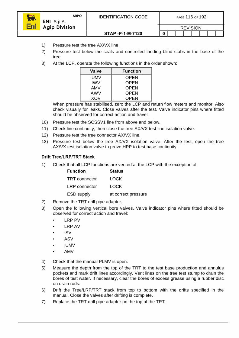
ARPO
ENI S.p.A.Agip Division
IDENTIFICATION CODE PAGE 116 OF 192
REVISIONSTAP -P-1-M-7120 0
1) Pressure test the tree AX/VX line.
2) Pressure test below the seals and controlled landing blind stabs in the base of thetree.
3) At the LCP, operate the following functions in the order shown:
Valve FunctionIUMVIWVAMVAWVXOV
OPENOPENOPENOPENOPEN
When pressure has stabilised, zero the LCP and return flow meters and monitor. Alsocheck visually for leaks. Close valves after the test. Valve indicator pins where fittedshould be observed for correct action and travel.
10) Pressure test the SCSSV1 line from above and below.
11) Check line continuity, then close the tree AX/VX test line isolation valve.
12) Pressure test the tree connector AX/VX line.
13) Pressure test below the tree AX/VX isolation valve. After the test, open the treeAX/VX test isolation valve to prove HPP to test base continuity.
Drift Tree/LRP/TRT Stack
1) Check that all LCP functions are vented at the LCP with the exception of:
Function Status
TRT connector LOCK
LRP connector LOCK
ESD supply at correct pressure
2) Remove the TRT drill pipe adapter.
3) Open the following vertical bore valves. Valve indicator pins where fitted should beobserved for correct action and travel:
• LRP PV• LRP AV• ISV• ASV• IUMV• AMV
4) Check that the manual PLMV is open.
5) Measure the depth from the top of the TRT to the test base production and annuluspockets and mark drift lines accordingly. Vent lines on the tree test stump to drain thebores of test water. If necessary, clear the bores of excess grease using a rubber discon drain rods.
6) Drift the Tree/LRP/TRT stack from top to bottom with the drifts specified in themanual. Close the valves after drifting is complete.
7) Replace the TRT drill pipe adapter on the top of the TRT.
ARPO
ENI S.p.A.Agip Division
IDENTIFICATION CODE PAGE 117 OF 192
REVISIONSTAP -P-1-M-7120 0
Final Tree/LRP/TRT Preparation
1) Refit the TRT drill pipe adapter to the top of the tree assembly.
2) Flush the SCSSV1 and AX/VX test lines from the LCP to the tree test stump.
3) At the LCP, unlock the flowline and wellhead connectors.
4) Verify LCP status for other functions.
5) Verify visually that the wellhead and flowline connectors are unlocked.
6) Pick up the full Tree/LRP/TRT stack with the main umbilical attached, taking extremecare not to exceed the minimum umbilical bend radius or over-stress theumbilical attachment point on the TRT.
7) Land the assembly in the correct orientation on the handling/support skid.
8) Replace all gaskets and seals in the underside of the wellhead and flowlineconnectors.
9) Set the tree manual valves as per the Operating Manual.
10) Perform a final pre-submergence check according to the Operating Manual.
11) When all checks are complete, pick up the Tree/LRP/TRT/main umbilical stack, andland out on the handling/support hub or skid beams.
12) When landed on a handling/support hub, lock the tree to the mandrel.
13) Remove the TRT drill pipe adapter in preparation for later fitting of the stress joint.
Summary of Tree System Pre-deployment Testing
A summary of the pre-deployment testing should be confirmed by checking off thechecks/tests in a table.
11.1.11. Production Riser
1) Carefully remove the sections of riser from the shipping baskets and lay out on thepipe rack.
2) Check that all joints, stress joint and surface joint are present.
3) Remove the protectors and check the connectors and connection seals for damageand replace, if necessary.
4) Ensure the connections are suitably covered in grease for weather protection.Replace the protectors.
5) Ensure sufficient riser handling tools are available and check connectors andconnection seals. Ensure riser handling tools have current certification.
ARPO
ENI S.p.A.Agip Division
IDENTIFICATION CODE PAGE 118 OF 192
REVISIONSTAP -P-1-M-7120 0
11.1.12. Surface Xmas Tree
The surface Xmas tree or terminal head should be removed from the shipping frame and allvalves tested from above and below to working pressure.
Ensure that the lift frame (if applicable) has been shipped and is undamaged. If long bailsare utilised, ensure they are located, identified and have current certification. These itemsmay be stored out of the way until immediately before they are required. Check that thelifting frame will not clash with the derrick structure. If coiled tubing services are requiredlater, it is recommended that a lift frame be utilised rather than long bails.
Where wireline adapters are fitted to the crown flange ensure that the necessary seals arein good order and any required crossovers are like wise identified.
11.2. DEPLOYMENT PROCEDURES
The following procedures are guidelines only and therefore engineers must ensure thatequipment specific procedures from the manufacturer’s Operating Manuals are used forequipment deployment.
11.2.1. Running The Completion And Tubing Hanger
1) Clear the rig floor of all non-essential tools and equipment.
2) Assemble well control crossovers to the safety or Kelly cock valves and clearly markfor easy identification. Set aside in an easily accessible place on the drill floor.
3) Move the TH handling string dual handling equipment to the rig floor.
4) Rig up the torque/turn analysis with powered tubing tongs equipped with integral backup tongs and stand back in the derrick.
5) Position the electrical cable/control line protectors in a drum on the rig floor and useonly from the drum as required. Tubing protectors must be removed placed in abasket immediately when removed from running joints.
6) Rig up the dual landing string elevators.
7) Pick up the THRT/THOJ/handling sub assembly and install on to a dummy or usedhanger, making up the THRT umbilical if not already made up.
8) Lock the THRT to the hanger, lock in the pressure at the umbilical reel and disconnectthe umbilical jumper.
9) Attaching the umbilical to the strings, run in the hole on drillpipe/tubing stands.
10) Run in the hole and on the compensator, gently tag the hanger in the wellheadrecording the exact depth that the weight drops off and marking the pipe at the rotarytable.
11) Repeat the procedure ensuring the depth remains the same.
12) Pull up until the tool is 10ft above the orientation key/slot (for whichever type ofsystem is being used. Hydraulically activate the orientation key and slowly lower thehandling string observing for orientation of the string. If the string does not turn, applya chain tong and check that it is correctly engaged in the slot. check the depth is thesame as found in step 10 above. Repeat the procedure if it is felt there may be anyuncertainty.
ARPO
ENI S.p.A.Agip Division
IDENTIFICATION CODE PAGE 119 OF 192
REVISIONSTAP -P-1-M-7120 0
1) If necessary to check the ram sealing ability on the THOJ, close the rams, install thesafety valves on the landing strings and test down the kill line to the appropriatepressure, usually 1,500psi. Painting the THOJ white will give confirmation that the toolhas been correctly positioned within the stack.
2) Bleed off the test pressure, open the rams and pull the landing string, strap the pipe ifnecessary.
3) Observe the paint on the THOJ and for signs on the dummy hanger that it wasproperly positioned.
4) Close the blind rams and disconnect the dummy hanger. Pick up the allocated TH andpack off into the rotary table and attach the THRT/THOJ to the hanger.
5) Check that the TH seals have not been damaged and install the protection cap. Standthe complete assembly back in the derrick.
6) Rig down the dual elevators and rig up the single completion handling equipment.
7) Ensure the completion sub-assemblies have been laid out in correct running orderand appropriately numbered.
8) Refer to completion installation procedures in section 8.
9) Run the string to the hanger installation point and, according to the completion designand procedures in the well programme, conduct the spacing out operations or installthe hanger/THRT assembly. Terminate and connect up the control line and electricalcable.
10) Pressure test the SCSSSV control line on the control panel. Check electricalcontinuity.
11) Conduct the final tubing pressure test and any other necessary tests according to theOperating Manual.
12) Run the completion string to depth on the hanger landing strings, locking pressure inall the correct functions.
13) When 10ft above the hang off point, activate the orientation mechanism and lower thehanger until soft landing into the wellhead.
14) Check the depth marks on the landing string confirming proper depth location. Checkwith chain tongs that the orientation slot is engaged. Repeat the procedure only ifabsolutely necessary as damage to the control line or cable may be caused by cyclingin and out of the hole.
15) Ensuring all the completion string weight has been hung off, proceed with the hangersetting and testing procedures as per the manufacturer’s Operating ProceduresManual which will test:
• Production string• Annulus string• Above the hanger• Below the hanger• All control or injection lines• DHPTT cable.
16) Rig up wireline and plug the well for BOP removal according to the well programme.
17) Unlatch the running tool from the hanger and retrieve the landing string to surface.
18) If applicable, run the TH orientation or verification tool.
ARPO
ENI S.p.A.Agip Division
IDENTIFICATION CODE PAGE 120 OF 192
REVISIONSTAP -P-1-M-7120 0
11.2.2. Pull The Drilling BOPs
Displace the riser to seawater and pull the stack as per the Eni-Agip Drilling ProceduresManual.
11.3. WORKOVER AND PRODUCTION CONTROLS SYSTEM PRE-DEPLOYMENTTESTING
11.3.1. Workover Controls Equipment
This section describes in outline the pre-test activities to be performed on:
• Workover Hydraulic Power Pack (HPP)• Local Control Panel (LCP)• Remote Control Panel (RCP)• Remote ESD Panel (RESDP)• Surface Tree ESD Panel (STESDP)• Main Workover Umbilical Reel (MUR)• Utility Workover Umbilical Reel (UUR)• TCR Umbilical Reel (TUR)• Hydraulic Interconnection Jumpers• Electrical Interconnection Jumpers• ESD Radio Link Remote Telemetry Unit (RTU)• ESD Radio Link Battery Unit• ESD Radio Link Antennae ‘A’ and ‘B’.
The arrangement of these are shown in figure 11.b.
The WOCS usually operates on three modes to accommodate running or retrieving:
a) Tubing Hanger System.
b) Subsea Xmas tree and workover riser.
c) Tree Cap.
11.3.2. Production Controls Equipment
This section describes in outline the pre-test activities to be performed on:
• Subsea Control Module (SCM)• Subsea Control Module Running Tool (SCMRT)• Subsea Control Module Flushing and Testing Unit (SCMFTU)• Portable Electronic Simulator Unit (PESU).
After each of the items are received onboard, a Site Received Test should first beperformed. It is then to be tested to confirm operation before use.
The pre-deployment test procedures for both systems is detailed in the following sections.
ARPO
ENI S.p.A.Agip Division
IDENTIFICATION CODE PAGE 121 OF 192
REVISIONSTAP -P-1-M-7120 0
Figure 11.B - Typical WOCS Layout
11.3.3. WOCS Pre-Deployment Testing
ES
D
Rad
io
Link
Ant
enna
'A'
Ant
enna
'B'
Bat
tery
SX
T E
SD
Pan
el
RC
P
Rem
ote
ES
DP
anel
SX
TC
ontr
olLi
nes
HP
PLC
P
Hyd
raul
icP
ower
Hyd
raul
icP
ower
Con
trol
Line
sC
ontr
olLi
nes
Mai
nU
mbi
lical
Ree
l
Util
ityU
mbi
lical
Ree
l
TR
T
LRP
SC
MR
TT
HO
J
Air
Air
XT
XT
TH
RT
Saf
e A
rea
Ele
crtic
al S
uppl
y
Air
Sup
ply
TC
RT
Um
bilic
alR
eel
TC
RT
Air
ARPO
ENI S.p.A.Agip Division
IDENTIFICATION CODE PAGE 122 OF 192
REVISIONSTAP -P-1-M-7120 0
All tests will be in accordance to the manufacturer’s Operating and Maintenance Manualand should meet the guidelines below.
System Test Procedure
Check and prepare the hydraulic supply panel as follows:
1) Ensure that all Site Received Inspections have been carried out and that ECR punchlists have been actioned.
2) Locate and secure all equipment in the locations shown in the Well Programme.Ensure they are properly earthed.
3) Check the status of all valves, adjustable controls and switches.
4) Attach dedicated air and electrical supplies to the HPP. These should be appropriatelymarked or locked to ensure they are not accidentally disconnected.
5) Connect air supplies to the MUR, UUR, and TUR.
6) Ensure the HPP has sufficient reserves of control fluid, and that accumulators are fullycharged.
7) Hook up to the HPP with the jumpers to the MUR and UUR.
8) Connect the electrical jumpers.
9) Establish the radio link with the Tiffany platform and function test.
10) Hook up the RCP, RESDP, STESDP and RTU.
11) Check the operation of the LCP functions.
12) Check the operation of the RCP functions.
13) Check the operation of the RESDP functions.
14) Check the operation of the STESDP functions.
15) Check the operation of the MUR functions.
16) Check the operation of the UUR functions.
17) Check the operation of the LCP functions.
18) Flush and test all control lines within jumpers and umbilicals, but not TCRT umbilicallines.
19) Check the operation of all reel air motors.
WOCS ESD Tests
This procedure tests the workover ESD function using the LCP, RCP and RESDP panelsand should be conducted after the full stack up integrity tests described in Section 7.10.
Note: During the following tasks the subsea ESD accumulator should re-chargeafter each ESD test, but allow 5min between tests to provide sufficienttime for re-charging.
ARPO
ENI S.p.A.Agip Division
IDENTIFICATION CODE PAGE 123 OF 192
REVISIONSTAP -P-1-M-7120 0
Perform WOCS ESD sequences as follows:
1) Ensure that the ESD accumulator on the LRP is fully charged and attach a suitablerange pressure gauge to the SCSSV1 line on the tree test stump. Check that the LCPand tree is correctly set according to the Manufacturers Instruction Manual.
2) Depress the workover ESD push-button at the LCP.
a) Verify that the following valves close:
• LRP PV• LRP XOV• LRP AV.
Record that the operating time until the last valve closes is according to the timespecified in the manual and within tolerance.
b) Verify that the next set of valves close:
• PWV• AWV• XOV• PSV• ASV• Methanol Injection Valve• Scale inhibitor Injection Valve.
Record that the operating time until the last valve closes is according to the timespecified in the manual and within tolerance.
c) Verify that the next set of valves close:
• PUMV• AMVRecord that the operating time until the last valve closes is according to the timespecified in the manual and within tolerance.
e) Verify that the SCSSV1 line depressurises at the correct time after the workoverESD button was pressed on the LCP.
f) Unlock the workover ESD push-button at the LCP.
g) Operate the workover ESD, reset push-button on the LCP after the ESDsequence is completed.
h) Verify that the workover ESD lamps at the LCP, RCP, and RESDP switch off.
3) Enable the RCP at the LCP and re-open all the actuated valves as per step 1 aboveat the RCP. Verify at the LCP gauges, SCSSV1 test base gauge and by visualinspection. Also check that the ESD supply is fully charged.
ARPO
ENI S.p.A.Agip Division
IDENTIFICATION CODE PAGE 124 OF 192
REVISIONSTAP -P-1-M-7120 0
1) Depress the workover ESD push-button at the RCP.
a) Valve closure should be identical to that monitored in step 2 overleaf.
b) Unlock the workover ESD push-button at the RCP.
c) Operate the workover ESD reset push-button on the LCP, after the ESDsequence is completed.
d) Verify that the workover ESD lamps at the LCP, RCP and RESDP switch off.
5) Disable the RCP at the LCP. Re-open all the actuated valves as per step 1 overleaf atthe LCP. Verify at the LCP gauges, SCSSV1 test base gauge and by visualinspection. Also check that the ESD supply is fully charged.
6) Depress the workover ESD push-button at the remote ESD panel.
a) Valve closure should be identical to that monitored in step 2 overleaf.
b) Unlock the workover ESD push-button at the remote ESD panel.
c) Operate the workover ESD reset push-button on the LCP, after the ESDsequence is completed.
d) Verify that the workover ESD lamps at the LCP, RCP, and RESDP switch off.
11.3.4. Production Controls Pre-Deployment Testing
This test sequence must be done during the pre-deployment testing on the subsea tree insection 11.1.9.
Function Test the Tree through the PESU
Hook-Up
1) Using the dedicated electrical cable provided, set up the PESU and hook up to thetree test stump electrical connection plate.
2) Power up the system and perform electrical checks.
3) Connect up LP, HP and return hydraulic lines to the tree test stump bulkhead platetaking supplies from either the HPP or the outboard end of either the main or utilityumbilical jumpers.
4) Power up the tree hydraulically.
ARPO
ENI S.p.A.Agip Division
IDENTIFICATION CODE PAGE 125 OF 192
REVISIONSTAP -P-1-M-7120 0
Check Sensors
1) Configure the PESU as a surface unit with the supplier’s protocol. Send a BREAKSTATE REQUEST COMMAND to SEM A. Verify that all valves and indicators areshown as ‘OK’.
2) Send an ANALOGUE DATA REQUEST COMMAND to SEM A. Verify that alltransmitters are indicated as ‘(tick)’.
3) Verify that readings for Annulus Pressure and Production Pressure are correct.Ensure that the bores are vented at the block elbows by opening the wing valves,hence ensuring pressure is not locked in.
Injection PressureAmbient pressure = __________ barg
PESU reading = __________ mA
Converted PESU reading =35016
x (PESU reading diff. from 4.00)
= __________ barg
(Acceptance criterion is +/- 2.2 bar)Annulus PressureAmbient pressure = __________ bargPESU reading = __________ mA
Converted PESU reading =35016
x (PESU reading diff. from 4.00)
= __________ barg(Acceptance criterion is +/- 2.2 bar)
4) Verify that reading for production temperature is correct by comparing it against acalibrated mercury-in-glass thermometer.
Mercury-in-glass thermometer reading _________oC
(Calibrated thermometer to be accurate to +/-0.5 oC)
PESU reading = _________ mA
Converted PESU reading =35016
x (PESU reading diff. from 4.00)
= _________ oC(Acceptance criterion is +/- 1.1 degrees C)
5) Switch on the DHPTT Simulator and set it to PANEX: 32 mA.
6) Send a number of DHPTT DATA REQUEST COMMANDS to SEM A until a DHPTTDATA MESSAGE is received.
7) Select Range Option 1 on the DHPTT Simulator, wait 20 seconds for stabilisation andsend a DHPTT DATA REQUEST COMMAND to SEM A. Check that valid data isreceived (i.e. the same frequencies as shown in the DHPTT simulator). Repeat forRange Option 2.
ARPO
ENI S.p.A.Agip Division
IDENTIFICATION CODE PAGE 126 OF 192
REVISIONSTAP -P-1-M-7120 0
Functional Tests using SEM A
Complete the following tests on the PUMV, then repeat them for the SCSSV1, PWV, AMV,AWV, XOV, SIV and MIV.
a) Record the results of these tests in table 11.a
Note: The operation of the SCSSV1 will be simulated bymonitoring/manipulating a needle valve/gauge on the SCSSV1 at the treetest base.
Take the opportunity to check the tree valve position indicators during these tests.
1) Check the displayed readings of LP supply and return volumes by sending anANALOG DATA REQUEST COMMAND. If the readings are not zero, transmitcommands to RESET the readings. Record that the readings have been reset in thetable.
2) Transmit a VALVE COMMAND to open the Production Tree valve specified in thetable.
3) Send a FUNCTION/STATUS REQUEST COMMAND to SEM A and check that thetree gate valve is indicated in the OPEN position.
4) Obtain the displayed readings of LP supply and return volumes by sending anANALOG DATA REQUEST COMMAND and record readings in the table.
5) Check on the XT that the valve actuator has moved to the energised position. In thecase of the simulated SCSSV1 valve, check on the gauge on the hook-up line comingfrom the tree test stump that the line has been energised.
6) Transmit RESET FLOW COUNTER COMMANDS to reset the LP supply and returnvolumes.
7) Transmit a VALVE COMMAND to close the production tree valve.
8) Send a FUNCTION/STATUS REQUEST COMMAND to SEM A and check that thetree gate valve is now indicated in the CLOSED position.
9) Obtain the displayed readings of LP supply and return volumes by sending anANALOG DATA REQUEST COMMAND and record readings in the table 11.a.
10) Check on the XT that the valve actuator has moved to the de-energised position. Inthe case of the simulated SCSSV1 valve, check the needle valve/gauge on the treetest base.
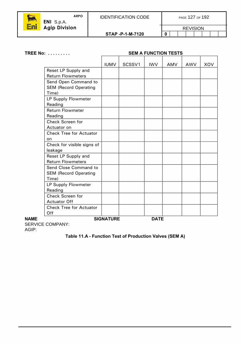
ARPO
ENI S.p.A.Agip Division
IDENTIFICATION CODE PAGE 127 OF 192
REVISIONSTAP -P-1-M-7120 0
TREE No: . . . . . . . . . SEM A FUNCTION TESTS
IUMV SCSSV1 IWV AMV AWV XOVReset LP Supply andReturn FlowmetersSend Open Command toSEM (Record OperatingTime)LP Supply FlowmeterReadingReturn FlowmeterReadingCheck Screen forActuator onCheck Tree for ActuatoronCheck for visible signs ofleakageReset LP Supply andReturn FlowmetersSend Close Command toSEM (Record OperatingTime)LP Supply FlowmeterReadingCheck Screen forActuator OffCheck Tree for ActuatorOff
NAME SIGNATURE DATESERVICE COMPANY:AGIP:
Table 11.A - Function Test of Production Valves (SEM A)
ARPO
ENI S.p.A.Agip Division
IDENTIFICATION CODE PAGE 128 OF 192
REVISIONSTAP -P-1-M-7120 0
11.3.5. Function Test using SEM B
Record the results of these tests in table 11.b.
1) Set the PESU to operate SEM B. Transmit a VALVE COMMAND to open the PUMVvalve.
2) Send a FUNCTION/STATUS REQUEST COMMAND to SEM B and check that thePUMV valve is indicated in the OPEN position.
3) Check on the tree that the PUMV valve actuator has moved to the energised position.
4) Transmit a VALVE COMMAND to open the SCSSV1 valve.
5) Send a FUNCTION/STATUS REQUEST COMMAND to SEM B and check that theSCSSV1 valve is indicated in the OPEN position.
6) Check the gauge on the tree test base that the SCSSV1 line has been energised.
7) Transmit a VALVE COMMAND to open the PWV valve.
8) Send a FUNCTION/STATUS REQUEST COMMAND to SEM B and check that thePWV valve is now indicated in the OPEN position.
9) Check on the tree that the PWV valve actuator has moved to the energised position.
10) Transmit a VALVE COMMAND to close the open PWV valve.
11) Send a FUNCTION/STATUS REQUEST COMMAND to SEM B and check that thePWV valve is now indicated in the CLOSED position.
12) Check on the tree that the PWV valve actuator has moved to the de-energisedposition.
13) Transmit a VALVE COMMAND to close the open PUMV valve.
14) Send a FUNCTION/STATUS REQUEST COMMAND to SEM B and check that thePUMV valve is now indicated in the CLOSED position.
15) Check on the Tree that the PUMV valve actuator has moved to the de-energisedposition.
16) Transmit a VALVE COMMAND to close the open SCSSV1 valve.
17) Send a FUNCTION/STATUS REQUEST COMMAND to SEM B and check that theSCSSV1 valve is now indicated in the CLOSED position.
18) Check the gauge on the tree test base that the line has been de-energised.
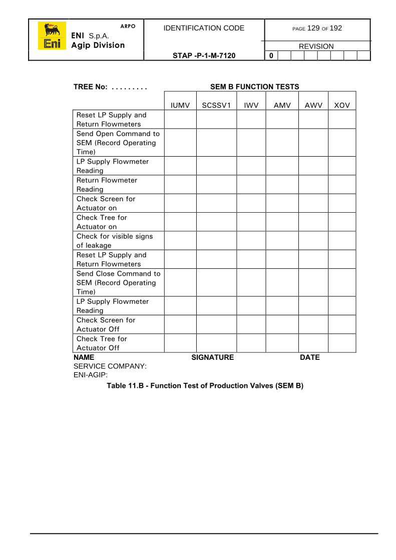
ARPO
ENI S.p.A.Agip Division
IDENTIFICATION CODE PAGE 129 OF 192
REVISIONSTAP -P-1-M-7120 0
TREE No: . . . . . . . . . SEM B FUNCTION TESTS
IUMV SCSSV1 IWV AMV AWV XOVReset LP Supply andReturn FlowmetersSend Open Command toSEM (Record OperatingTime)LP Supply FlowmeterReadingReturn FlowmeterReadingCheck Screen forActuator onCheck Tree forActuator onCheck for visible signsof leakageReset LP Supply andReturn FlowmetersSend Close Command toSEM (Record OperatingTime)LP Supply FlowmeterReadingCheck Screen forActuator OffCheck Tree forActuator Off
NAME SIGNATURE DATESERVICE COMPANY:ENI-AGIP:
Table 11.B - Function Test of Production Valves (SEM B)
ARPO
ENI S.p.A.Agip Division
IDENTIFICATION CODE PAGE 130 OF 192
REVISIONSTAP -P-1-M-7120 0
Simulation of Level 1 Shutdown
1) Transmit VALVE COMMANDS to open all production and chemical injection valves.
2) Send a FUNCTION/STATUS REQUEST COMMAND to SEM A and check that allvalves are indicated in the open position.
3) Check that all valves on the tree are energised.
4) Simulate a Level 1 Shutdown by transmitting VALVE COMMANDS as follows:
• CLOSE PWV• After 20sec CLOSE PUMV.
5) Confirm that the valves on the tree follow the same sequence. Send an FSR to verify.
Simulation of Level 2 Shutdown
1) Transmit VALVE COMMANDS to open all production and chemical injection valves.
2) Send a FUNCTION/STATUS REQUEST COMMAND to SEM A and check that allvalves are indicated in the open position.
3) Check that all valves on the Xmas tree are energised.
4) Simulate a Level 2 Shutdown by transmitting VALVE COMMAND as follows:
• CLOSE PWV• After 5sec CLOSE AWV• After 5sec CLOSE AMV• After 5sec CLOSE CV• After 5sec CLOSE PUMV• After 5sec CLOSE SIV• After 5sec CLOSE MIV.
5) Confirm that the valves on the tree follow the same sequence. Send an FSR to verify.
Simulation of Level 3 and Level 4 Shutdowns
1) Transmit VALVE COMMANDS to open all production and chemical injection valves.
2) Send a FUNCTION/STATUS REQUEST COMMAND to SEM A and check that allvalves are indicated in the open position.
3) Check that all valves on the XT are energised.
4) Simulate Level 3 and Level 4 Shutdowns by transmitting VALVE COMMANDS asfollows:
• CLOSE PWV• After 5sec CLOSE AWV• After 5sec CLOSE AMV• After 5sec CLOSE CV• After 5sec CLOSE PUMV• After 5sec CLOSE SIV• After 5sec CLOSE MIV• After 5sec CLOSE SCSSV1.
5) Confirm that the valves on the tree follow the same sequence. Send an FSR to verify.
ARPO
ENI S.p.A.Agip Division
IDENTIFICATION CODE PAGE 131 OF 192
REVISIONSTAP -P-1-M-7120 0
11.3.6. Pressure Test Tree Valves
This section describes the procedure for pressure testing each side of every valve on thetree. This activity should be performed according to the Manufacturers Operating Manualbut with the tree connected to the tree test base and the tree cap and SCM installed. In allcases, valve control will be effected from the PESU, and tests must be chart recorded.
The XT/Tree cap controls interfaces will have been previously tested, however, theSCM/MMB interface should also be checked during these tests for leakage. This isachieved by monitoring the flow of hydraulic fluid at the PESU.
1) Test the valves according to the sequence shown in table 11.a and check off eachtest performed on chart in table 11.d.
2) The SCSSV1 and tree AX test line manual isolation valves will be tested later whenthe LRP/TRT are stacked on the tree.
3) When tests are complete, vent down the LP and HP supplies and power down theSCM. Leave all functions vented.
Recheck SCM Operation
Re-test SCM functions against the blanked snaptite couplers at the top of the tree asfollows:
1) Check that the PESU and hydraulic supplies are hooked up per section 11.3.4.
2) Check tree sensors also according to section 11.3.4.
Function Check
Production PressureAnnulus PressureProduction TemperatureDHPTT
3) Verify SCM valve functions using SEM A. As the LRP is installed to the top of the tree,the tree valves will not function when operated through the SCM and PESU, however,valve supply lines will be pressurised up to the tree receiver plate and the SCM willgive a 'pressurised' status for that line.
Check valve functions in the following order:
• IUMV• SCSSV1• IWV• AMV• AWV• XOV.
Record the results in table 11.e.
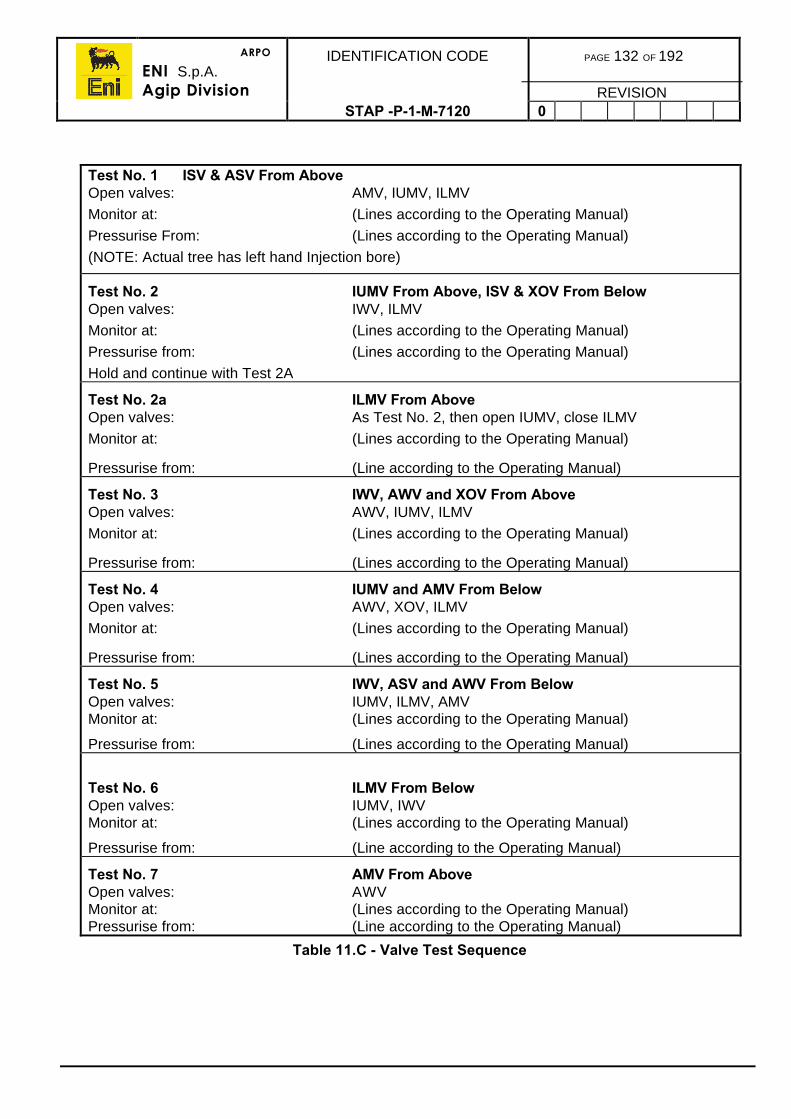
ARPO
ENI S.p.A.Agip Division
IDENTIFICATION CODE PAGE 132 OF 192
REVISIONSTAP -P-1-M-7120 0
Test No. 1 ISV & ASV From AboveOpen valves: AMV, IUMV, ILMV
Monitor at: (Lines according to the Operating Manual)
Pressurise From: (Lines according to the Operating Manual)
(NOTE: Actual tree has left hand Injection bore)
Test No. 2 IUMV From Above, ISV & XOV From BelowOpen valves: IWV, ILMV
Monitor at: (Lines according to the Operating Manual)
Pressurise from: (Lines according to the Operating Manual)
Hold and continue with Test 2A
Test No. 2a ILMV From AboveOpen valves: As Test No. 2, then open IUMV, close ILMV
Monitor at: (Lines according to the Operating Manual)
Pressurise from: (Line according to the Operating Manual)
Test No. 3 IWV, AWV and XOV From AboveOpen valves: AWV, IUMV, ILMV
Monitor at: (Lines according to the Operating Manual)
Pressurise from: (Lines according to the Operating Manual)
Test No. 4 IUMV and AMV From BelowOpen valves: AWV, XOV, ILMV
Monitor at: (Lines according to the Operating Manual)
Pressurise from: (Lines according to the Operating Manual)
Test No. 5 IWV, ASV and AWV From BelowOpen valves: IUMV, ILMV, AMVMonitor at: (Lines according to the Operating Manual)
Pressurise from: (Lines according to the Operating Manual)
Test No. 6 ILMV From BelowOpen valves: IUMV, IWVMonitor at: (Lines according to the Operating Manual)
Pressurise from: (Line according to the Operating Manual)
Test No. 7 AMV From AboveOpen valves: AWVMonitor at: (Lines according to the Operating Manual)Pressurise from: (Line according to the Operating Manual)
Table 11.C - Valve Test Sequence
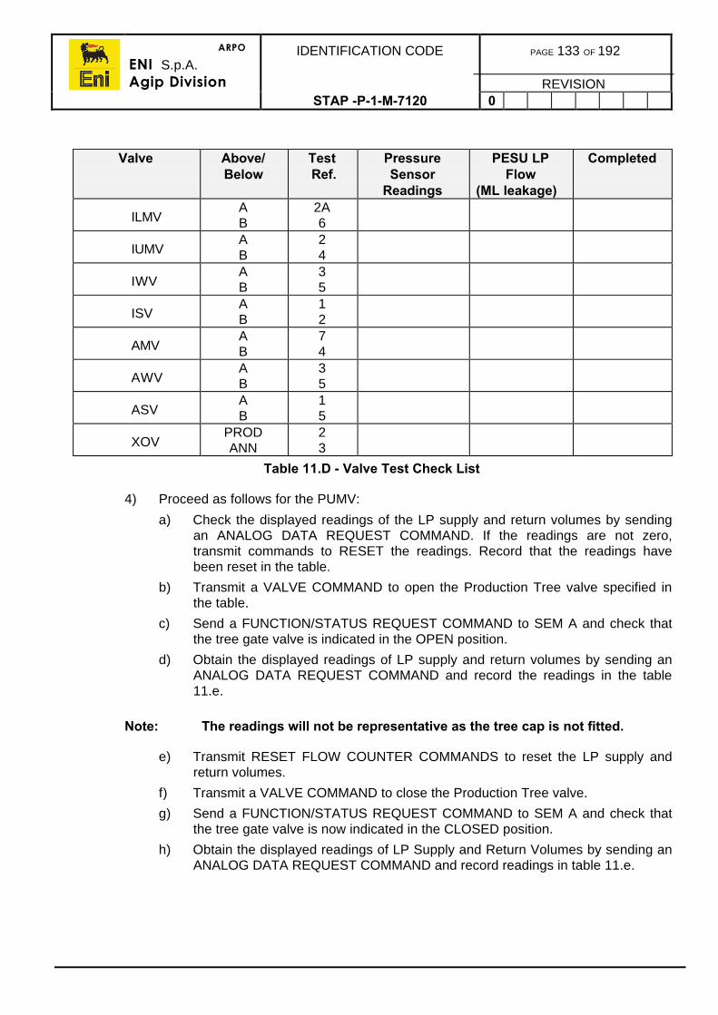
ARPO
ENI S.p.A.Agip Division
IDENTIFICATION CODE PAGE 133 OF 192
REVISIONSTAP -P-1-M-7120 0
Valve Above/Below
Test Ref.
PressureSensor
Readings
PESU LPFlow
(ML leakage)
Completed
ILMVAB
2A6
IUMVAB
24
IWVAB
35
ISVAB
12
AMVAB
74
AWVAB
35
ASVAB
15
XOVPRODANN
23
Table 11.D - Valve Test Check List
4) Proceed as follows for the PUMV:
a) Check the displayed readings of the LP supply and return volumes by sendingan ANALOG DATA REQUEST COMMAND. If the readings are not zero,transmit commands to RESET the readings. Record that the readings havebeen reset in the table.
b) Transmit a VALVE COMMAND to open the Production Tree valve specified inthe table.
c) Send a FUNCTION/STATUS REQUEST COMMAND to SEM A and check thatthe tree gate valve is indicated in the OPEN position.
d) Obtain the displayed readings of LP supply and return volumes by sending anANALOG DATA REQUEST COMMAND and record the readings in the table11.e.
Note: The readings will not be representative as the tree cap is not fitted.
e) Transmit RESET FLOW COUNTER COMMANDS to reset the LP supply andreturn volumes.
f) Transmit a VALVE COMMAND to close the Production Tree valve.
g) Send a FUNCTION/STATUS REQUEST COMMAND to SEM A and check thatthe tree gate valve is now indicated in the CLOSED position.
h) Obtain the displayed readings of LP Supply and Return Volumes by sending anANALOG DATA REQUEST COMMAND and record readings in table 11.e.
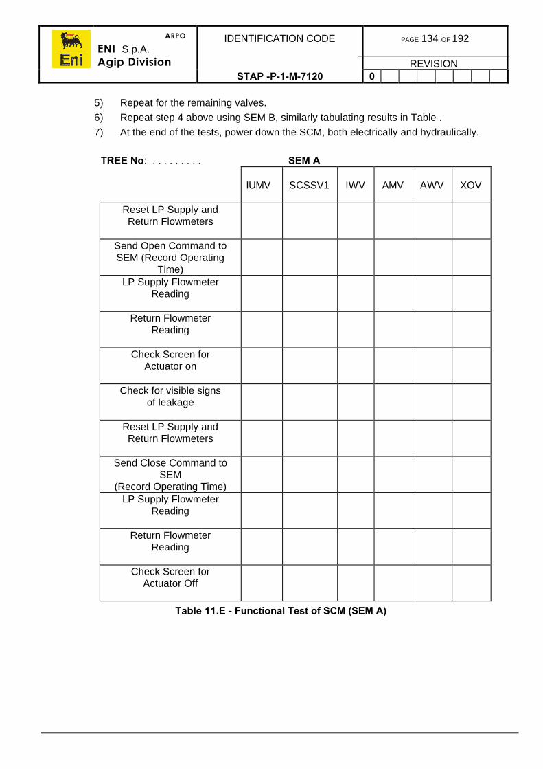
ARPO
ENI S.p.A.Agip Division
IDENTIFICATION CODE PAGE 134 OF 192
REVISIONSTAP -P-1-M-7120 0
5) Repeat for the remaining valves.
6) Repeat step 4 above using SEM B, similarly tabulating results in Table .
7) At the end of the tests, power down the SCM, both electrically and hydraulically.
TREE No: . . . . . . . . . SEM A
IUMV SCSSV1 IWV AMV AWV XOV
Reset LP Supply andReturn Flowmeters
Send Open Command toSEM (Record Operating
Time)LP Supply Flowmeter
Reading
Return FlowmeterReading
Check Screen forActuator on
Check for visible signsof leakage
Reset LP Supply andReturn Flowmeters
Send Close Command toSEM
(Record Operating Time)LP Supply Flowmeter
Reading
Return FlowmeterReading
Check Screen forActuator Off
Table 11.E - Functional Test of SCM (SEM A)

ARPO
ENI S.p.A.Agip Division
IDENTIFICATION CODE PAGE 135 OF 192
REVISIONSTAP -P-1-M-7120 0
TREE No: . . . . . . . . . SEM B
IUMV SCSSV1 IWV AMV AWV XOVReset LP Supply andReturn Flowmeters
Send Open Command toSEM (Record Operating
Time)LP Supply Flowmeter
Reading
Return FlowmeterReading
Check Screen forActuator on
Check for visible signsof leakage
Reset LP Supply andReturn Flowmeters
Send Close Command toSEM
(Record Operating Time)LP Supply Flowmeter
Reading
Return FlowmeterReading
Check Screen forActuator Off
Table 11.F - Functional Test of SCM (SEM B)
8) Repeat for the remaining valves.
ARPO
ENI S.p.A.Agip Division
IDENTIFICATION CODE PAGE 136 OF 192
REVISIONSTAP -P-1-M-7120 0
11.4. RUNNING THE SUBSEA XMAS TREE
Ensure all pre-deployment testing in accordance to the guidelines in 11.1 and the specificOperations Manuals has been fully completed.
1) If the hanger orientation or verification tool is a post BOP removal type, run the tooland check the hanger. This tool is also sometimes used to jet out above the hangerprior to running the tree.
2) Ensure the rig is position over the safe deployment area (at least 50 ft away from anywellhead).
3) Move the tree/LRP/TRT assembly directly under the rotary table on the moonpooltrolley, ensuring the proper orientation of the assembly to the guidewires and, hence,the permanent guidebase.
4) Lower the riser adapter and stress joint through the rotary table and make up to theTRT.
5) Connect up the main umbilical and sheaves hanging them from a pre-selected fixingpoint.
6) Activate the tree connector unlock and release it from the stump. Lock pressure inother connectors as necessary per the Operations Manual. Pick up the completeassembly and install the guidewires. Remove the stump and moonpool trolley.
7) Lower the riser through the rotary and land off on the riser spider. Pressure test theriser adapter by applying pressure through the riser bores via the test sub against theLRP valves.
8) Remove the test sub and open the tree bore and LRP valves. Lock them open at theumbilical reel then disconnect the jumper umbilical.
9) Proceed and run the tree on riser sections clamping the umbilical to the riser belowthe rig floor over the safe deployment area.
10) Land the upper tension joint on the spider which will position the tree +/-30ft abovethe wellhead. Install the surface tree and lift frame, long bails or strops.
11) Pull off enough umbilical for landing off the tree and reconnect the jumper hose.
12) On the compensator, lower the riser until the tree is approx. 10ft above the wellhead.Pressure test the surface tree and riser against the LRP valves.
13) Open all the tree bore valves and LRP valves, move the rig over the well and gentlylower and soft land the tree on the wellhead.
14) Lock the tree connector to the wellhead and observe the indicator by ROV.
15) Conduct an overpull to confirm the connector is properly engaged. Transfer the riserweight to the tensioners and maintain a top tension as per the figures from theOperations Manual.
16) Pressure test all seals and function test as per the Operations Manual.
17) Function all tree hydraulic valves to check for proper operation confirmed by the ROV.
11.4.1. Unplugging The Well
1) Rig up wireline and pressure test.
2) Run and pull the wireline plugs.
ARPO
ENI S.p.A.Agip Division
IDENTIFICATION CODE PAGE 137 OF 192
REVISIONSTAP -P-1-M-7120 0
11.4.2. Perforating And Well clean-Up
The normal shut-in and flow will be performed through the surface tree while the gate valveon the lower master is designed to cut wireline and coiled tubing in the case of anemergency.
To create an underbalance and conduct the well clean up, refer to the completion section12.
1) Initiate perforating operations.
2) Bring the well onstream through the surface well test package and clean the well uptesting the DHPTT.
3) Close in the well at surface.
4) Install wireline plugs for temporary suspension and commissioning activities on thetree and flowlines.
11.5. PULLING THE LRP
1) After installing the wireline plugs, bleed off pressure in the production bore and inflowtest the plugs. Close the tree swab and upper master valve. Close the lower master byROV.
2) Check the valves are closed by ROV camera.
3) Displace the riser to seawater and close the LRP XOV.
4) Set down weight (Refer to the Operating Manual) and unlock the LRP connector.
5) Pick up the LRP from the tree and rig down the surface tree and surface riser joint.
6) Pull the riser.
7) When the LRP reaches surface with the stress joint through the rotary table, move theLRP stump below the LRP on the BOP transfer trolley.
8) Lower the LRP onto the stump and lock using a hotline if necessary.
9) Disconnect the stress joint and pull to the drill floor.
10) Move the LRP/tree running tool to the storage/work area.
11.5.1. Disconnect The LRP And Tree Running Tool
1) Disconnect all control jumpers and umbilicals.
2) Attach the TRT lift cap to the TRT mandrel.
3) Unlock the TRT from the LRP and pick up the TRT from the LRP.
4) Set the TRT on it’s storage frame.
5) Attach the cap to the LRP.
6) Disconnect all control jumpers and umbilicals.
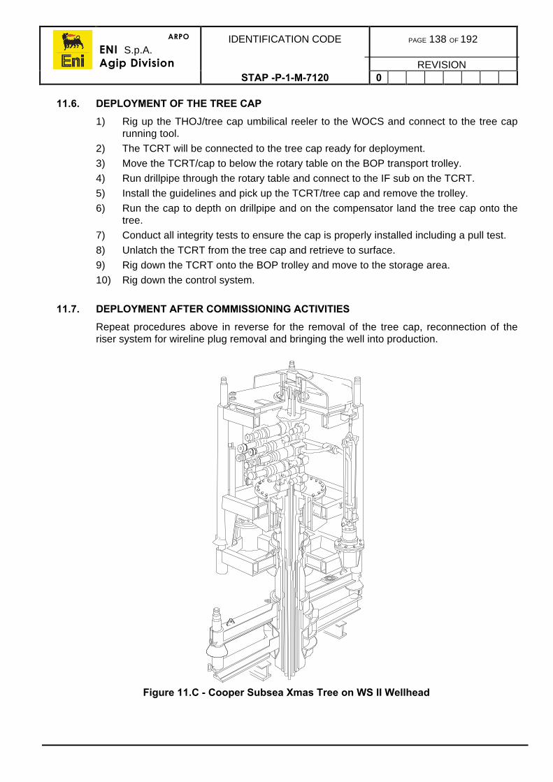
ARPO
ENI S.p.A.Agip Division
IDENTIFICATION CODE PAGE 138 OF 192
REVISIONSTAP -P-1-M-7120 0
11.6. DEPLOYMENT OF THE TREE CAP
1) Rig up the THOJ/tree cap umbilical reeler to the WOCS and connect to the tree caprunning tool.
2) The TCRT will be connected to the tree cap ready for deployment.
3) Move the TCRT/cap to below the rotary table on the BOP transport trolley.
4) Run drillpipe through the rotary table and connect to the IF sub on the TCRT.
5) Install the guidelines and pick up the TCRT/tree cap and remove the trolley.
6) Run the cap to depth on drillpipe and on the compensator land the tree cap onto thetree.
7) Conduct all integrity tests to ensure the cap is properly installed including a pull test.
8) Unlatch the TCRT from the tree cap and retrieve to surface.
9) Rig down the TCRT onto the BOP trolley and move to the storage area.
10) Rig down the control system.
11.7. DEPLOYMENT AFTER COMMISSIONING ACTIVITIES
Repeat procedures above in reverse for the removal of the tree cap, reconnection of theriser system for wireline plug removal and bringing the well into production.
Figure 11.C - Cooper Subsea Xmas Tree on WS II Wellhead
ARPO
ENI S.p.A.Agip Division
IDENTIFICATION CODE PAGE 139 OF 192
REVISIONSTAP-P-1-7120 0
12. WELL UNLOADING
Following the successful completing of a well, it will normally have been left with thecompletion fluid left in both the tubing and annulus. To enable the well to produce undernatural flow conditions (i.e. non artificial lift) the overbalance pressure exerted by thecompletion fluid must be removed, sometimes referred to as ‘unloading’. The well may bebrought onstream direct into the production facility but is often tested with a well testpackage to be cleaned up prior to placing it on production (this is normal practice for subseacompletions where the production of the well straight into the subsea flowline systemwithout cleaning up may plug and perhaps damage the facilities).
If losses have occurred during the drilling and completion phases, the hydrostatic pressurein the tubing needs to be reduced to such an extent that the replenishing losses flowingback into the wellbore does not kill the well again. It is normal practice to circulate anunderbalanced fluid into the tubing using a circulating device or coiled tubing service, whichwill provide sufficient underbalance to enable the well to flow under the conditions stated.The fluid used is usually selected to provide as large drawdown as possible at low cost.
Under some circumstances, an underbalance can be achieved by simply bullheading alighter fluid into the tubing relying on produced gas to maintain the underbalance duringflowback. This is a cost effective method if bullheading is acceptable for a particularformation.
The fluids normally used may be water, base oil, diesel or nitrogen. Nitrogen can becirculated by deploying the coiled tubing and continuously gas lifting the well until naturalflow is established. It may also be installed like the other fluids by pumping it into the tubingtaking returns through a circulating device and out of the annulus. The depth to which theunderbalance fluid is circulated depends upon the drawdown which can be achieved.
Continuous gas lifting a well is preferred if there has been large losses otherwise thecirculation process may have to be repeated more than once causing higher costs, thisneeds to be evaluated.
The procedures for circulation are given in this section. The procedures for nitrogen liftingare given in section 14 and coiled tubing procedures in section 13.
12.1. UNLOADING BY CIRCULATION
It is assumed that any suspension plugs in the well above the circulation device have beenremoved and that the completion fluid occupies the tubing. It may be prudent to leave orinstall a plug or standing valve in the packer tailpipe to prevent losses during this procedure.
If it is planned to place the maximum amount of fluid in the well to obtain the highestdrawdown, ensure that it is not over-displaced into the annulus.
1) Rig up wireline in accordance to the procedures in the Company Wireline ProceduresManual.
2) Rig up the circulating pump to the Xmas tree kill wing and pressure test to 1,000psiabove the maximum anticipated wellhead pressure or to WP.
3) Rig up a return line from the annulus to a returns tank of sufficient capacity. pressuretest these lines against the side outlet valves with a pump..
ARPO
ENI S.p.A.Agip Division
IDENTIFICATION CODE PAGE 140 OF 192
REVISIONSTAP -P-1-M-7120 0
1) Pressure test the wireline lubricator to a minimum of 1,000psi above the maximumanticipated wellhead pressure or to WP.
2) Install the circulating device opening or shifting tool. If using a SPM, install the SPMdummy valve pulling tool.
3) Run in the hole and open the circulating device. There should be no differentialpressure across the device as there is completion fluid on both sides.
4) Confirm the circulation path is open by pumping up on the tubing and observingpressure on the annulus.
5) Pull out of the hole. With some particular SSDs, it is sometimes possible to run twotools in one run to open and close the sleeve in one trip (parking it below the SSDduring circulation).
6) If a SPM is being used, run and install a circulating valve in the pocket and pull out ofthe hole.
7) With the return system from the annulus open, begin to pump the underbalance intothe tubing monitoring the volume pumped and the volume of returns from the annulus.
8) Continue pumping until the calculated amount of fluid has been pumped. Check thatthe surface ‘U’ tube pressure is correct for the volume of underbalance fluid pumpedaccording to calculation and hold this pressure on the pump.
9) Run in the hole and close the circulating device. In the case of a SPM, reinstall thedummy valve. Confirm closure by pressuring up on the annulus and observing nopressure on the tubing or any significant volume is pumped.
10) Pull out of the hole.
11) Rig up, run in the hole and pull the packer tailpipe plug or standing valve, if used.
12) Rig down wireline and the pump lines.
13) Ensure the production flowline is lined up to flow to the production facilities and thatthe production operators are informed that the well will produce back through theirfacilities.
14) Open the production wing valve.
15) Gradually open the production choke to flow the well.
16) Monitor the wellhead pressure, slowly opening the choke as it is assured that the wellis successfully unloading.
17) Continue until the well has stable flowing conditions at a reasonably high rate(reservoir engineering will provide the flowing parameters).
ARPO
ENI S.p.A.Agip Division
IDENTIFICATION CODE PAGE 141 OF 192
REVISIONSTAP -P-1-M-7120 0
12.2. UNLOADING BY BULLHEADING
If bullheading and if reservoir conditions allow, the following procedure could be used.
1) Rig up the pump to the Xmas tree kill wing and pressure test to 1,000psi above themaximum anticipated wellhead pressure or to WP.
2) Open the kill wing and with the pump lined up to the supply of underbalance fluid,(liquid or nitrogen) begin displacing the tubing. Never pump at a pressure to exceedbottomhole fracture pressure. Monitor the pressure trend is consistent.
3) When the calculated volume has been pumped, shut down the pump and record thestatic surface pressure confirming the correct amount of fluid has been pumped.
4) Close the kill wing valve.
5) Ensure the production flowline is lined up to flow to the production facilities and thatthe production operators are informed that the well will produce back through theirfacilities.
6) Open the production wing valve.
7) Gradually open the production choke to flow the well.
8) Monitor the wellhead pressure, slowly opening the choke as it is assured that the wellis successfully unloading.
9) Continue until the well has stable flowing conditions at a reasonably high rate(reservoir engineering will provide the flowing parameters).
12.3. UNLOADING BY COILED TUBING
Refer to section 14.
ARPO
ENI S.p.A.Agip Division
IDENTIFICATION CODE PAGE 142 OF 192
REVISIONSTAP -P-1-M-7120 0
13. COILED TUBING OPERATIONS
13.1. PREPARATION
Coiled tubing (C/T) operations will not be allowed to commence without an approved workprogramme.
The Completions and Workover Superintendent will confirm that the well to be worked on isavailable and accessible. Should the rig be required, then he will confirm its availability andthe manning requirements.
A pre-job meeting should be held well in advance of the actual operation. The purpose ofthis meeting is to:
• Discuss the programme of operations.• Establish channels of communication and define responsibilities.• To discuss any special requirements or circumstances that may arise e.g.
procedures in the case of emergency, adverse weather conditions, ID of stringcomponents versus tool OD, escape of hazardous treatment fluids, etc.
• Additional topics will be discussed as required and may include working inconfined spaces, working with pressurised equipment, handling of heavyequipment, etc.
Make sure a completion diagram of the well is available. This should include the location ofcasing, tubing shoe, packers, perforations, etc., as well as KOP and maximum angle ofdeviation. A brief written outline of previous relevant well operations should be given to thecoiled tubing supervisor.
The Completions and Workover Superintendent will ensure that all relevant equipment andmaterials for the job are on site in a timely manner.
13.2. SAFETY CONSIDERATIONS
Safety during C/T operations, in common with most operations in a potentially dangerousenvironment, is largely dependent on sound operating procedures and effectivecommunication. The following points are, essentially, common sense and should beobserved during all phases of the operation:
• Keep well clear of the tubing at all times.• Tubing can part due to excess pressure and tubing wear. Beware of the physical
damage due to thrashing pipe, as well as spraying treatment fluids.• If the tubing becomes stuck and excessive pressure and pull are to be applied,
clear the area as required. Make an announcement over the PA system toinform personnel.
• Do not stand near treating lines, pumps, tanks, reel, injector, or under thetubing.
• There should be no overhead lifts across or near the tubing.• Safety harnesses will be used when operating above ground level. This includes
working on top of the reel and injector as well as in the derrick.• When treating the well with hazardous chemicals the relevant safety wear must
be worn by all personnel in the work area (Refer to section 15.2).
ARPO
ENI S.p.A.Agip Division
IDENTIFICATION CODE PAGE 143 OF 192
REVISIONSTAP -P-1-M-7120 0
• Before rigging up coiled tubing, a safety meeting will be held with all relevantpersonnel. The topics to be covered will include, but are not be limited to:a) Working with pressurised equipment
b) Handling of heavy equipment
c) Use of hazardous chemicals
d) Safe working areas
e) Emergency procedures
f) Protective clothing
g) etc.
• Communication with the operator in the C/T control cabin, the drill floor/skiddeck and the control room will be maintained throughout the operation.
• All personnel should be aware of the Emergency Procedures for C/T operations.
13.2.1. Tubing
The coiled tubing should be treated like a pressure vessel. While operating or pressuretesting it will contain several cubic meters of gas, fluid, or energised fluid. Unlike a pressurevessel however, it undergoes considerable stress during running and also suffers from bothinternal and external corrosion. Therefore, ensure that the reel carries a full and up-to-dateoperational history, which should include the following information:
• The cycle history of the whole reel length (one cycle being a run in followed bythe run out).
• The treatment history, i.e. what fluids have passed through the reel.• The well conditions. What fluids and gases were in the well being treated, e.g.
H2S, Acid.• The condition of welds or joins in the reel, i.e. are they original, are X-rays
available of the welds, etc.• The records showing when was the last non-destructive test of the full reel
length.
13.2.2. Risers and BOPs
As the riser and BOPs are, in effect, a pressure vessel situated above the Xmas tree,subjected to the wellhead shut in pressure and test pressures, it is essential that the sealsare regularly checked and that they are pressure tested every time the BOPs are broken outfor tool recovery etc.
1) When pulling coiled tubing tools into the riser, it should be at the slowest possiblespeed to be selected.
2) The riser must be depressurised and any gas/fluids bled off via the choke to the testseparator. The toolstring must be pulled up against the BOPs, prior to breaking outthe BOP connection.
3) After the riser has been depressurised, the riser, or BOP bleed off needle valve mustbe opened to verify that all pressure and fluids have been vented, prior to breakingthe BOP connection to remove the tool string.
ARPO
ENI S.p.A.Agip Division
IDENTIFICATION CODE PAGE 144 OF 192
REVISIONSTAP -P-1-M-7120 0
1) After de-pressuring the Xmas tree and riser but before the BOP is broken out, theswab valve must be closed. This is to prevent any possible hazardous conditionarising due to the inadvertent opening of a wing valve, or flow from a leaking mastervalve.
13.2.3. H2S Considerations
When working on wells which are known H2S producers, or those in which H2S isanticipated, ensure that hydrogen sulphide detectors and portable breathing apparatus setsare available and on site.
Safety aspects of well operations in the presence of H2S must be addressed in the pre-jobsafety meeting. This applies to all wells where the presence of H2S is known or anticipated.When H2S bearing wells are to be entered for C/T workover purposes, the Xmas tree is tobe flushed with water/glycol to remove all traces of H2S prior to rigging up on the well. Allpersonnel involved in these operations will wear automatic H2S detectors and be equippedwith self contained breathing apparatus.
13.3. PERMIT REQUIREMENTS
Note: All permits will be issued in accordance with the Permit to Work System.
1) No operations can begin without the relevant work permits.
2) Obtaining and distribution of the permits is the responsibility if the ContractorsRepresentative.
3) All permits will be revalidated at the end of each shift.
Note: Permits may not be valid for 12 hours on crew change days.
4) Obtain the relevant Permits to Work in accordance to the PTW system.
5) The Contractor Representative will ensure that all relevant work permits have beensigned and distributed, and inform the Well Operations Supervisor that this has beendone.
6) The Area Authorities/Safety Officer may, if required, will make an inspection to ensurethat there is no other work going on which may affect the operation.
7) The Well Operations Supervisor will confirm the well status and accept the wellhandover certificate from the Production Supervisor.
8) Certain operations may require lifting of heavy equipment over live wells. Whereverpossible this will be avoided. If circumstances make the lift unavoidable, then theProduction Supervisor will be informed. He will decide if any live well needs to be shutin and if scaffolding of other protective structure needs to be erected.
9) Only equipment with valid test certificates will be used for rigging up and during theoperation.
10) All well control equipment must have current certification of conformity issued by thecertifying authority.
ARPO
ENI S.p.A.Agip Division
IDENTIFICATION CODE PAGE 145 OF 192
REVISIONSTAP -P-1-M-7120 0
13.4. RIG UP PROCEDURES
13.4.1. Equipment Preparation and Siting
1) Ensure that the equipment has been visually checked for defects prior to starting rig-up.
2) If time allows, a permit should be obtained and the equipment run and tested, prior tothe commencement of the operation, to check equipment function and confirm theoperation of the shut down systems on the power pack.
3) The Well Operations Supervisor should ensure that:
• The work area is suitably guarded (e.g. safety barriers, safety signs, etc.).• Any scaffolding is secure, safe and properly certified.• The crane operator and roustabouts are aware of the equipment weights and
hazards (e.g. liquid nitrogen or acid, etc.).• All lifts should have tag lines attached.
13.4.2. Coiled Tubing Rig-Up
Note: The C/T unit will be function tested on the deck prior to it being made upin the well.
Note: It is Company policy to run a remote hydraulic control shear seal BOP atthe bottom of the riser immediately above the tree.
Refer to figure 13.a General rig up arrangement.
1) Confirm that the tree has been de-pressurised and the controls have been isolatedfrom the main control system.
2) Take control of the well from Production Department.
3) Remove the swab cap and inspect the thread and seal areas.
4) Run the riser (with the shear seal BOP at the bottom) onto the tree and pressure testwith water to 500 psi above the maximum anticipated surface pressure or to themaximum test pressure of 5,000 psi, whichever is lower. Do not exceed themaximum allowable tree rating.
5) Position the tubing reel and power pack so that the coiled tubing has an unrestrictedpath to the injector head.
6) Move the BOP assembly onto the rig floor or skid deck, make up to riser and pressuretest. Function test the BOP with both panels, fill up the riser and BOP withglycol/water, close the blind rams and pressure test the riser, return lines and blindrams to 500psi above the maximum anticipated surface pressure, or to the maximumtest pressure of 5,000psi, whichever is lower.
7) Clamp the coiled tubing at the reel using a certified clamp but not molegrips or othersimilar tools.
8) The injector head may be rigged up and the tubing stabbed through the injector headon the catwalk or drill floor depending on space available.
ARPO
ENI S.p.A.Agip Division
IDENTIFICATION CODE PAGE 146 OF 192
REVISIONSTAP -P-1-M-7120 0
1) When picking up the injector head, use tugger lines to keep the assembly vertical.Tugger lines must not be attached to the injector body, as this will interfere with theweight indicator readings.
2) Fill the reel with water. The reel should be flushed with water and pigged with a no-goprior to running packers and other sensitive tools to gauge reel volume, ensure thatthere are no restrictions to the ID of the coil and to purge any debris form the tubing.Make-up and fit the end connector and test sub. Test reel to full test pressure andperform pull test before stabbing on to BOP.
3) Attach the C/T BHA, and stab the injector onto the BOP.
4) The assembly will be pressure tested with the BHA across the BOP.
13.4.3. Pressure Testing
Pressure testing of the coiled tubing assembly, which includes the BOPs, tubing, treatinglines and the pump, should be carried out in a logical sequence to eliminate all possibleleaks.
1) The Blind Rams and Riser will have already been tested while rigging up the BOPs,therefore it is certain the BOP to riser seal, riser to tree seal, swab valve, BOP killwing valve and blind rams have pressure integrity.
2) If using an in-line tubing connector, the Stripper/Packer and Toolstring will be testedwith the tools across the BOP and the straight bar in the energised stripper. With thewhole system full of water, pressure is applied from the pump in stages of 500psi upto a maximum of 5,000psi. The pump and treating lines up to the reel will have beentested already. Do not exceed the maximum allowable tree rating.
3) If using an out-line tubing connector, the Stripper/Packer and Toolstring will be testedwith the tools below the BOP. With the whole system full of water, pressure is appliedthrough the tubing in stages of 500psi up to a maximum of 5,000psi, to preventcollapse of the tubing.
4) The Pipe Rams are now tested by closing the pipe rams and bleeding the pressuredown to zero via the circulating port on the BOP. Once the test is complete, close thecirculating port and equalise the pressure across the pipe rams.
5) The Check Valves in the toolstring are now checked using the pressure already in thesystem. With the straight bar still across the still energised stripper, bleed down thepressure at the reel. The check valves should seal, and pressure will remain in theriser and BOPs while the reel pressure is zero. When bleeding down reel pressure,ensure external pressure does not exceed the collapse pressure rating of the reel.
6) Alternatively, bleed down the whole system at the BOPs and with the reel valve open,using the cement or pressure test pump, pressure test check valves via a pump-in teebelow the BOPs while stripper is energised.
7) The BOPs should be bled down after the testing is completed.
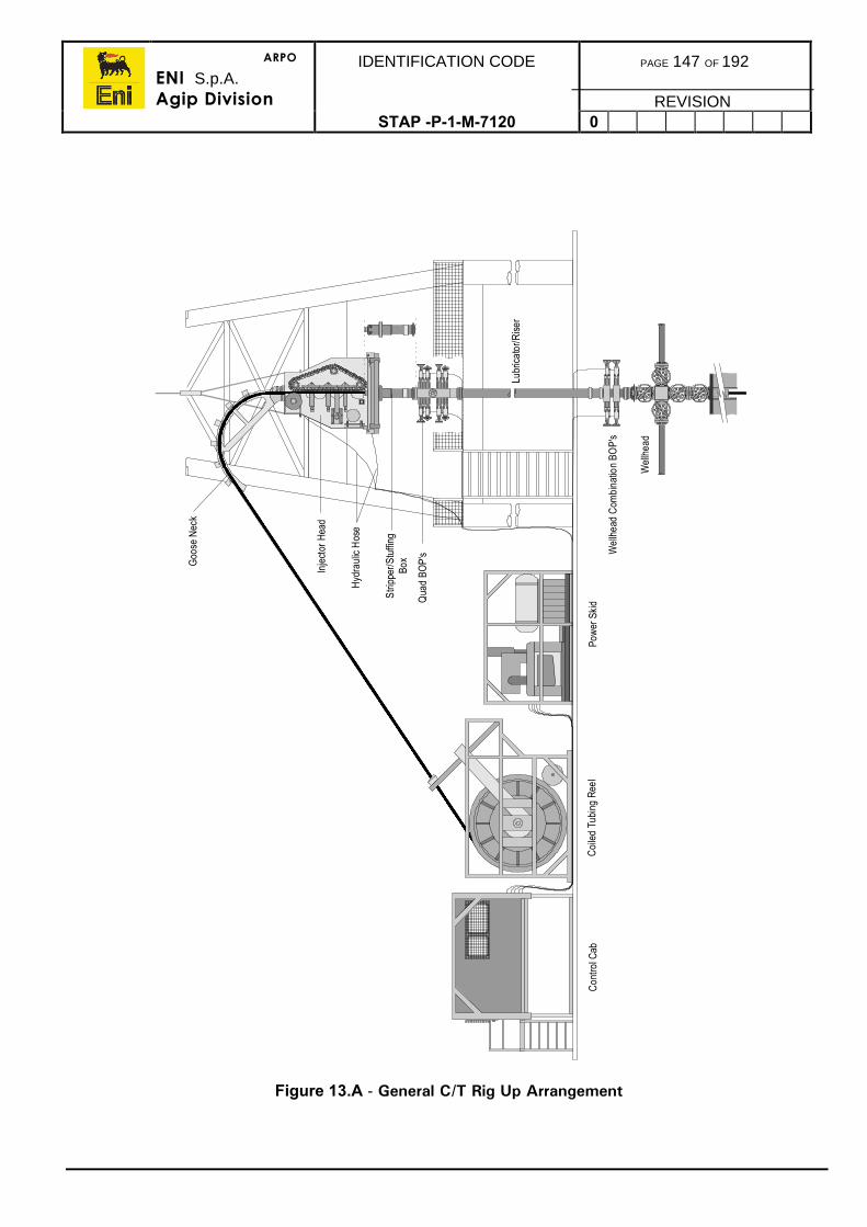
ARPO
ENI S.p.A.Agip Division
IDENTIFICATION CODE PAGE 147 OF 192
REVISIONSTAP -P-1-M-7120 0
Figure 13.A - General C/T Rig Up Arrangement
Con
trol C
abC
oile
d Tu
bing
Ree
lPo
wer
Ski
d
Goo
se N
eck
Inje
ctor
Hea
d
Hyd
raul
ic H
ose
Stri
pper
/Stu
ffing
Box
Qua
d BO
P's
Lubr
icat
or/R
iser
Wel
lhea
d C
ombi
natio
n BO
P's
Wel
lhea
d
ARPO
ENI S.p.A.Agip Division
IDENTIFICATION CODE PAGE 148 OF 192
REVISIONSTAP -P-1-M-7120 0
13.4.4. Treating Lines
• On all C/T operations, treating lines should be rigged-up using certified Fig.1502integral lines.
• Any bent lines or damaged unions will be marked, registered as unfit for use andreturned to base.
• Ensure that the lines are tied with safety cables and attached at regular intervalsto secure fixing points.
• Ensure that check valves are used on wellheads, reels and each pump.• Ensure that a certified relief valve is installed in the surface line circuitry. The
relief valve setting is to be confirmed between the Company and ContractorRepresentative prior to equipment load out.
• All valves should be tested from the well side including the last valve on the reel.
13.4.5. Injector Frame
An injector frame is used to steady and position an injector when operated rigless. It mayalso be used when operating through the rig although this is not recommended as it servesno purpose and requires additional rig-up time.
On floaters a special lifting frame or extra long bails should be attached to the block to thesurface tree to maintain tension through the compensation system. The injector is theninstalled inside the lift frame or bails. This enhances the safety of personnel and enableseasy rig up of the injector head on a heaving rig.
The injector frame is not designed to withstand the weight of the injector and the weight ofthe coiled tubing in the hole. This combined weight, which can be in the region of 20tonnes, is carried by the wellhead. The purpose of the frame is only to ensure lateralstability.
Most frames have hydraulic height adjustment and should include hydraulic compensationsystems to allow for any vertical movement of the wellhead in relation to the deck.
The frame should be pegged to the injector and tied back at the four top corners usingcertified chains and come-alongs, to secure fastening points on the deck.
The injector should remain connected to the crane or overhead gantry crane during theoperation to add stability to the structure and to facilitate rapid removal of the injector duringrig down. Due to possible contraction of the riser due to well cooling, no tensionshould be applied to crane sling during operations.
13.4.6. Rigging Down
To rig down:
1) Pull out of the hole until the tubing end connector tags the stripper. Use no more than4,000lbs overpull.
2) Close off the well isolation valve.
3) Bleed off pressure in the coiled tubing and surface lines through the closed line drainin case of any hydrocarbon discharge.
4) Rig down the coiled tubing and associated equipment.
5) Ensure all equipment is stowed safely for transport.
ARPO
ENI S.p.A.Agip Division
IDENTIFICATION CODE PAGE 149 OF 192
REVISIONSTAP -P-1-M-7120 0
13.5. RUNNING PROCEDURES
The following procedures are guidelines, the actual toolstring configuration, running speedsand operating procedures will vary depending on the work being performed.
1) The basic toolstring configuration for conventional circulation operations is, from thebottom up:
• Circulating nozzle• Two check or flapper valves• Straight bar• Tubing connector.
2) Refer to the toolstring configuration in the well programme for specific operations.
3) The weight indicator must be tested before running coiled tubing in to a well.
4) Ensure the mechanical and electronic depth counters are set to zero at theappropriate zero datum reference.
5) Standard running speed should be 50ft/min, running or pulling through unobstructedtubing, slowing to 15ft/min within 50ft either side of obstructions.
6) Running speeds will be reduced when running through the riser, Xmas tree, SCSSVand any other downhole restrictions.
7) Ensure that the tubing internal pressure is maintained at all times by pumping. Onspecifically sanctioned operations, a differential of 1,000psi will be allowed across thetubing.
8) At any indication of the tubing hanging up, pull up well above hang up depth and liaisewith the Eni-Agip representative before taking further steps.
9) Particular care must be exercised when pulling the assembly out through the SCSSVand the Xmas tree and into the lubricator.
10) The C/T contractor will provide plots of pipe weight, pipe loading and buckling stressagainst depth for the particular job to be performed. Any significant deviations fromthese plots during the operation must be investigated.
11) Pulling weight tests/checks should be performed every 1,000ft regularly duringrunning in.
ARPO
ENI S.p.A.Agip Division
IDENTIFICATION CODE PAGE 150 OF 192
REVISIONSTAP -P-1-M-7120 0
13.6. OPERATING PROCEDURES
13.6.1. Gas Lifting
Gas lifting may be required to kick-off a well, which contains a kill fluid, in low pressureproducers when production has been temporarily halted. It is also used to remove a deadcolumn of fluid from closed tubing. Each specific condition requires an exact programme,however the basic procedure still applies.
When kicking off a well containing a kill fluid follow the basic procedure in this section. Allowsufficient nitrogen to remove any kill fluid that may have entered the formation during the killoperation. As a rule do not use excessive pump rates as this will lead to high annulusfriction and nitrogen may be lost to the formation. In wells exceeding 40o deviation nitrogenslippage is likely to occur. You should allow sufficient nitrogen to compensate for thisslippage.
When restoring production in low pressure wells that have been temporarily shut in, use lownitrogen rates and only run to a maximum of 50% of well depth. These wells only requireencouragement until water cut has been reduced and temperature has risen.
When removing a fixed dead column of fluid from a well, as when creating a nitrogencushion prior to DST or TCP, follow the main procedure, except that the well will not flowand dry gas should be produced at surface.
The procedures in this section are guidelines only, specific operational programmes will beissued by the Company.
Safety
A safety meeting will be held with all relevant personnel prior to any job. The meeting willaddress the hazards inherent with handling liquid nitrogen (Refer to section 14.7). Themeeting will also address the actions to be taken in the event of an emergency.
Procedures
1) Rig up and test the coiled tubing (Refer to section 13.4)
2) The nitrogen tanks, converter and pumping unit should be positioned close to thetubing reel in order to minimise the length of pressurised lines.
3) Reduce the test separator pressure according to the coiled tubing contractorsprocedures, and line up the well to the test separator.
4) Allow any gas cap on the well to vent off through the test separator.
5) Confirm that the tree and SCSSV controls have been isolated from the main controlsystem.
6) Equalise pressure across the swab valve then open.
7) Run in the well carefully, stopping to establish nitrogen injection at a low rate,increasing the rate slowly as the coiled tubing is further run in.
• If the well begins to slug nitrogen, reduce the injection rate• Shut down the nitrogen unit at the first indication of any rapid build up in
wellhead pressure.8) Once the tubing has reached the predetermined depth, stop running in and continue
pumping nitrogen until nearly all the nitrogen is pumped, or the well is flowing strongly.
ARPO
ENI S.p.A.Agip Division
IDENTIFICATION CODE PAGE 151 OF 192
REVISIONSTAP -P-1-M-7120 0
Note: Pull the tubing out of the well before the nitrogen supply is completelyexhausted. This is to ensure that the pressure differential across thetubing wall does not exceed 1,000psi.
1) Rig down and hand the well over to the Production Department.
2) The following data will be recorded throughout the nitrogen lift operation:
• Wellhead flowing pressure• Nitrogen injection pressure• Nitrogen injection rate• Wellhead flowing temperature• Separator level• Separator pressure• Separator temperature.
3) Fluid samples will be taken from the flow line sample point by the Well OperationsSupervisor.
13.6.2. Well Treatment
Well treatments can be performed using various acid and solvent formulations to improveproduction or injection rates. Coiled tubing is often used to perform well treatments,because it allows for the direct application of the treatment to the zone or area requiringtreatment.
The main types of treatment are as follows:
• Removal of scale from well tubulars and SCSSV• Matrix acidisation of the formation• Well bore clean-up using solvents and or acid.
Scale removal can be achieved by circulating acid across the area requiring treatment.
Note: Much of the acid may remain unspent and that this may have an effect onsurface flowlines and production equipment. Specific formulations may berecommended by the contractor to remove sulphate scale, and scalecontaining hydrocarbons.
Matrix acidisation of the formation can take the form of a small acid wash injected from thecoiled tubing directly to the zone requiring treatment, or for larger treatments, with the coiledtubing being used to circulate the acid to fill the tubing prior to direct high rate injection fromsurface. If leaving the coiled tubing in the well ensure that it is sufficiently inhibited and thatthe internal pressure of the C/T remains equal to or above the external pressure.
Well bore clean-ups are performed to remove scale, debris and waxes from the perforationtunnels. They are not intended to penetrate the formation, which could lead to additionaldamage. The treatment is applied by jetting the treatment fluid into the perforations whileslowly cycling the nozzle across the perforations. The treatment is performed with the wellbalanced or slightly underbalanced to prevent treatment fluid penetration.
ARPO
ENI S.p.A.Agip Division
IDENTIFICATION CODE PAGE 152 OF 192
REVISIONSTAP -P-1-M-7120 0
Safety
Prior to rigging up the acid equipment a safety meeting will be held with all relevantpersonnel (Refer to section 15.5). The meeting will address the hazards inherent withhandling acids, particularly under pressure. The meeting will also address the actions to betaken in the event of an emergency.
Procedure
The following details the basic procedures to be followed when performing acid treatmentsthrough coiled tubing:
1) Rig up and test coiled tubing (Refer to section 13.4).
2) Suggested BHA is, from the bottom up:
• Jetting nozzle• 2 dart type check valves• 6ft straight bar• Tubing connector.
3) Confirm that the tree and SCSSV controls have been isolated from the main controlsystem.
4) Pig the reel to determine accurate reel volume.
5) Equalise pressure across the swab valve then open.
6) Run in the well carefully, circulating at minimum rate. Perform regular pull tests/checksat 1,000 ft intervals.
7) Once the area to be treated has been reached, pump treated injection qualityseawater in order to establish the circulating pressure.
8) If an acid wash or solvent treatment is to be performed then:
• Circulate the coiled tubing to treatment fluid• ϑet the area to be treated while reciprocating the coiled tubing slowly• Circulate the tubing to injection quality seawater• Pull out of the hole.
9) If matrix acidising is to be performed the treatment formulation and volume will beadvised in a separate programme. However the basic procedure is:
• Circulate the treatment fluid into the well at the maximum rate.• Pull the tubing assembly above the acid and inject at a high rate via the tubing
and the tubing annulus simultaneously. (Alternatively the coiled tubing can bepulled out of the well before injecting the acid.)
• Pull out of the hole and if required flow the well with nitrogen.
Inhibition
It is essential that a sufficient quantity of inhibitor is used in the acid system. If a mutualsolvent is being used, the inhibitor content must be doubled due to the detrimental effectthat the solvent has on inhibitor efficiency.
A slug (5-10bbl), with 5% inhibitor in injection quality seawater, should be circulated aheadof the acid treatment. This will give protection to both the inside and outside of the tubing.
ARPO
ENI S.p.A.Agip Division
IDENTIFICATION CODE PAGE 153 OF 192
REVISIONSTAP -P-1-M-7120 0
13.6.3. Sand Cleanout
General
1) It may be necessary to clean out sand fill from a well to provide a sufficient sump forproduction logging, additional perforating and to exposed covered perforations. Sandclean out is best carried out using C/T. The clean out is carried out by running thetubing and pumping viscous fluid (gel) to lift the sand from the sump.
2) The clean-out operation may be carried out with the well flowing to assist the return ofsand to the surface. This is especially useful when the well is highly deviated, has alarge bore production string or when the well is unable to support a column of gelledseawater without incurring losses.
3) It is essential to keep circulating when there is a sand column in the production tubing.This is especially important when the well is not flowing, otherwise the C/T willbecome surrounded in sand and stuck.
Safety
Prior to rigging up the coiled tubing and circulating equipment a safety meeting will be heldwith all relevant personnel. The meeting will address the hazards of handling chemicals anduse of pressurised equipment. The meeting will also address the actions to be taken in theevent of an emergency.
Procedure
1) Ensure that the well is lined up to take returns to the test separator.
Note: The separator should be sand washed prior to the operation.
1) A sample point will be installed in the return line.
2) Rig up and test the coiled tubing (Refer to section 13.4).
3) Suggested BHA is, from the bottom up:
• Jetting Nozzle• 2 dart type check valves• 6ft straight bar• Tubing connector.
4) The required gel system should be prepared in a mixing tank and transferred to aholding tank containing agitators once it is fully hydrated.
5) Confirm that the Xmas Tree and SCSSV controls have been isolated from the maincontrol system.
6) Equalise pressure across the swab valve then open it.
7) Begin running in carefully with the well producing at a reduced rate. Keep the tubingstring filled full of treated sea water by circulating at the minimum rate. Carry outregular pull tests/checks at 1,000ft intervals.
8) Once the string is below the SCSSV, increase the production rate to its normal level.
9) Break circulation when well above the last recorded hold up depth and establish aminimum circulation rate while pumping gel.
ARPO
ENI S.p.A.Agip Division
IDENTIFICATION CODE PAGE 154 OF 192
REVISIONSTAP -P-1-M-7120 0
Note: Monitor the pump pressure, wellhead pressure and coiled tubing stringweight continuously throughout the operation. If there are any indicationsof problems pull back above the last hold up depth immediately andevaluate the situation.
1) Run in slowly to the top of the fill, stopping to note the hanging weight. Slow downwhen the weight begins to drop off the tubing and flag pipe at surface as a reference.The tubing must be kept in tension at all times.
2) After penetrating 20ft, pick-up to the tubing shoe then run back in to repeat theprocess in stages of 20ft, pumping continuously.
3) Having reached the required depth, continue to pump gel while reciprocating thetubing back to the tubing shoe twice. Carefully monitor fluctuations in pick-up weights.If an increase is seen, wash back until weight corresponds with the initial runningweight.
4) Pull up above the perforations and displace the tubing to treated seawater.
5) Pull out with the well flowing to ensure that all sand moving up as the tubing isremoved.
6) Rig down and hand control of the well back to Production.
7) Sand wash the test separator and record the volume of sand removed.
ARPO
ENI S.p.A.Agip Division
IDENTIFICATION CODE PAGE 155 OF 192
REVISIONSTAP-P-1-7120 0
14. NITROGEN PROCEDURES
The use of nitrogen is potentially hazardous and many precautions need to be taken toobtain a successful safe operation.
14.1. PREPARATION
1) No nitrogen operations will be allowed to commence without an approved workprogramme.
2) The Completions and Workover Superintendent will confirm that the well to be treatedis available and accessible. Should the rig be required then he will confirm itsavailability and the manning requirements.
3) A pre-job meeting should be held well in advance of the actual operation. Thepurpose of this meeting is to:
• Discuss the programme of operations.• Establish channels of communication, and define responsibilities.• To discuss any special requirements or circumstances that may arise, e.g.
procedures in the case of emergency, adverse weather conditions, safety datasheets, escape of gaseous or liquid nitrogen or energised fluids, etc.
• Additional topics will be discussed as required, and may include working inconfined spaces, working with energised fluid, extreme low temperatures,handling of heavy equipment etc.
4) A brief written outline of previous relevant well treatments should be given to thestimulation supervisor, or nitrogen operator.
14.2. SAFETY CONSIDERATIONS
Safety during a nitrogen operation, in common with most operations in a potentiallydangerous environment, is largely dependent on sound operating procedures and effectivecommunication. The following points are essentially common sense and should beobserved during all phases of the operation.
• Do not stand near treating lines, cryogenic hoses, nitrogen converters/pumps,liquid nitrogen tanks, or any other treating equipment during operations.
• There should be no overhead lifts across or near the liquid nitrogen tanks,treating lines or nitrogen converters/pumps.
• Safety harnesses will be used when operating above ground level. This includesworking on top of the liquid nitrogen tanks, as well as in the derrick.
• When treating the well with hazardous chemicals in conjunction with nitrogenrefer to the Stimulation Section regarding the wearing of additional safety wear.
• Before rigging up treating equipment a safety meeting will be held with allrelevant personnel. The topics to be covered will include, but not be limited to,working with pressurised equipment, gas pressure and energised fluids,handling of heavy equipment, handling of liquid nitrogen and gaseous nitrogen,use of hazardous chemicals, safe working areas, emergency procedures,protective clothing, etc.
• Only authorised personnel wearing adequate protective clothing will be allowedin the vicinity of the equipment while a nitrogen operation is being performed.
ARPO
ENI S.p.A.Agip Division
IDENTIFICATION CODE PAGE 156 OF 192
REVISIONSTAP -P-1-M-7120 0
• Good communications between the nitrogen operator, rig floor, wellhead areaand coiled tubing or stimulation operator where applicable must be maintainedthroughout the operation.
• All personnel should be aware of the Emergency Procedures for C/T operations.• All work areas will be chained or roped off, and warning signs placed at access
routes. The exact requirements will be specified on the work permits.• Fire hoses will be available in the areas where liquid nitrogen is to be used. The
hoses will be fully charged, so that they can be used immediately should a spilloccur.
• The nitrogen tanks and nitrogen converter/pump will be positioned as close tothe well as possible to minimise the length of pressurised lines.
• Gaseous nitrogen will escape from nitrogen tanks continuously as the tank iswarmed. Do not stand in the immediate vicinity of escaping nitrogen and do notattempt to plug or block the escaping gas.
• Nitrogen is not toxic (it represents about 80% of the air we breathe) but ifreleased in a confined area it will displace some of the oxygen present leadingto an oxygen poor atmosphere and possibly asphyxiation of people present.(The effect is like putting a plastic bag over one’s head.) Do not enter or work ina confined area where nitrogen is escaping.
• Liquid nitrogen is very cold being a cryogenic fluid. It will freeze flesh on contactalmost instantly, especially if the surface is water wet. The freezing effect isanaesthetic and may not be immediately noticed. The flesh or eye once frozenis effectively destroyed. The affected area will be treated as a serious burn.
• Lines carrying liquid nitrogen are also very cold and should only be handled withdry insulated gloves.
• On contract with steel, liquid nitrogen causes embrittlement and shrinkage of thesurface leading to fracture generation. Thus if nitrogen is split on a steel deck, itwill quite rapidly freeze and crack the deck, allowing the liquid to spill to the nextlevel. Apply a fine spray of water to the spill immediately. As in a liquid fire, donot apply a fierce jet to the liquid as this will disperse it to other areas. The finespray will lay down an insulating layer of ice on the deck and help evaporate theliquid nitrogen.
14.3. NITROGEN HANDLING
14.3.1. Safety Equipment
• When handling or working in the vicinity of a nitrogen operation, suitable safetyequipment must be made available and used. The type of safety equipmentrequired will depend on whether the person expects to operate the equipment orsimply remain in the vicinity.
• As standard procedure when in the vicinity of nitrogen operations, chemicalgoggles should be worn in preference to safety spectacles. Nitrogen operatorsmust be equipped with dry thermal gloves for handling cryogenic hoses andvalves.
ARPO
ENI S.p.A.Agip Division
IDENTIFICATION CODE PAGE 157 OF 192
REVISIONSTAP -P-1-M-7120 0
14.3.2. Safety Data Sheets
• When operating with nitrogen or any kind of chemical, ensure that the safetydata sheets are available both at the safety meeting and in the work area.
• During the safety meeting the Safety Officer should be shown each of the safetydata sheets. The safety officer should analyse the sheet and point out thehazards and handling instructions for nitrogen and any other chemical beingutilised.
• The control and disposal of spills of liquid nitrogen and escapes or leakages ofliquid or gaseous nitrogen should be explained.
• In the event of injury from nitrogen burn or asphyxiation the safety data sheetswill be available to enable the Medic and Safety Officer to determine the bestaction.
14.3.3. Pressurised Lines
• During nitrogen operations pressure will be used to inject the nitrogen as gasinto the well and for the pressurised transfer of liquid nitrogen between tanksand from tank to pump.
• The pressure will either be gas pressure or energised fluid pressure. It isimportant to note that when operating with energised fluid pressure, it isessential to keep the operational personnel in safe areas when ever possible.The effect of energised fluid pressure release is explosive.
14.4. RIG-UP PROCEDURES
14.4.1. Equipment Preparation and Siting
• The contractor will have a rig up procedure that has been approved by theCompany in advance.
• The equipment will be situated such that the length of pressurised lines, andliquid nitrogen hoses, are minimised.
• All high pressure lines will be pressure tested with water according to the valuesstated in the nitrogen programme.
• Where possible the nitrogen operator will have an unobstructed view of the rigfloor, or wellhead area, and the coiled tubing operator where relevant.
• Personnel involved in the operation will carry radios at all times.
14.4.2. Equipment Rig-up
• When rigging up equipment, ensure that all pressure operating items carry validtest certificates. Inspect all items for wear or damage and do not use anydefective items.
• Ensure equipment location has sufficient clear escape routes.• Liquid nitrogen lines should be supported off steel decks with wood or rubber
matting to prevent deck freezing.• Drip trays of stainless steel construction should be placed under all hose unions.• Liquid nitrogen tanks may not be stacked, either while being stored or during
operation.
ARPO
ENI S.p.A.Agip Division
IDENTIFICATION CODE PAGE 158 OF 192
REVISIONSTAP -P-1-M-7120 0
14.4.3. Pressure Testing
• Pressure testing should be performed with all lines and spaces to be tested fullof water.
• Testing with nitrogen should be avoided.• Pressure testing will take place to 1.5 times the maximum operating pressure.
Note: The pressure testing will be witnessed by the Well Operations Supervisor.
• Pressure tests will be monitored for 15 mins on a chart recorder. The chart willbe labelled and stored for reference.
• The PRV is to be isolated during pressure test.
14.4.4. Treating Lines
• Inspect all treating lines thoroughly. Mark and set aside defective treatingequipment.
• Ensure treating line runs are kept as short and direct as possible withoutcausing unnecessary obstruction.
• When treating at high rates and as a general practice, ensure sufficient flexibilityin the treating line by incorporating chicksan bridges in the line. Cavitation andhigh pump rates can stress lines and back off unions by vibration unless the lineis flexible.
• Lines should be tied together using a steel cable and clamps. Each individualline, swing or other treating pipe, should be clamped to the cable.
• The lines should also be tied off where possible to fixed objects such as padeyes.
• Ensure that each fluid or nitrogen pump is fitted with a check valve. A checkvalve should also be fitted to the treating point, i.e. coiled tubing reel, well head,kill line.
• Check valves should be fitted with bleed-off needle valves.
14.4.5. Rigging Down
• Rigging down will only take place once the Workover Superintendent orcompany representative has given permission.
• The existing Hot Work permit may be used if still valid otherwise a new ColdWork permit may be obtained.
ARPO
ENI S.p.A.Agip Division
IDENTIFICATION CODE PAGE 159 OF 192
REVISIONSTAP -P-1-M-7120 0
14.5. NITROGEN TREATMENT PROCEDURES
When preparing a nitrogen programme, note should be taken of the quantity of nitrogenrequired by calculation to complete the operation. To this should be added considerableexcess for ordering, to ensure that sufficient nitrogen is available to complete the job.Evaporation of stored nitrogen, due to shipping and job delays, multiple pressure test cool-downs, job restarts and other unexpected losses, suggest an excess allowance of at least50% over the calculated volume.
The following operational factors should be considered:
• The maximum flow rate required and the number of nitrogen converter/pumpsrequired.
• Contingency for unit breakdowns.• Space on the pipe deck to store the nitrogen beside the nitrogen converters and
pumps.• Quantity of nitrogen required to prevent restocking being craned in during the
operation.• Safety transfer of nitrogen between tanks during the operation.
A nitrogen pumping schedule will be prepared in advance by the service company. If duringthe nitrogen operation there are any significant variations from this schedule the job will beshut down and the cause investigated. If necessary, the operation will be adjusted andrestarted.
14.5.1. Pressures
• Nitrogen pump pressures should be determined before the start of a job. This isof particular importance with gas lifting. If the job is not correctly designed thecombined coiled tubing friction pressure and negative hydrostatic effect can leadto high surface pump pressure which may exceed the maximum allowable coiledtubing pressure.
• The maximum working pressure of wellheads and production equipment shouldalso be considered when designing nitrogen operations. High pressure gaspockets may return to surface.
14.5.2. Pump Rates
• Pump rates will be clearly stated in the individual stimulation programme.Generally the analogue gauges on nitrogen pumps and tanks are not veryaccurate and allowance should be made for this.
14.5.3. Coiled Tubing Gas Lift
A detailed programme is available in the Coiled Tubing Section 13.6.1
ARPO
ENI S.p.A.Agip Division
IDENTIFICATION CODE PAGE 160 OF 192
REVISIONSTAP -P-1-M-7120 0
14.5.4. Nitrogen Cushion - Tubing Conveyed Perforation
Nitrogen is used to allow control and adjustment of the drawdown pressure during tubingconveyed perforation operations. The general term used here is differential perforating.
The standard procedure follows:
• Once the tubing has been pressure tested for integrity using water, a circulatingsleeve is opened above the packer and nitrogen is injected down the tubing.
• Nitrogen displaces the water out of the circulating port until the desired fluidheight is achieved. The port is closed and nitrogen is pumped until the correctpressure is achieved on top of the water cushion.
• Normally 500-1,000 psi drawdown is required to ensure that, when the guns arefired, the perforation debris is ejected from the perforation tunnels and fluid isprevented from entering the perforation.
• Alternatively if circulation is not possible, coiled tubing may be used to circulateout the fluid used to pressure test the tubing. Coiled tubing should be run toabout 500 ft below the desired top of water cushion to ensure that sufficientwater is expelled. An amount of fluid will fall back after nitrogen lifting hasceased.
• The precise calculations for the amount of nitrogen required will be provided bythe service company by customised computer design packages.
ARPO
ENI S.p.A.Agip Division
IDENTIFICATION CODE PAGE 161 OF 192
REVISIONSTAP -P-1-M-7120 0
14.5.5. Nitrified Treatment
• Nitrified treatments are performed when the well being treated is unable tosupport a full column of treatment fluid. The nitrogen is injected into thetreatment fluid thus reducing the density of the fluid and, hence, allowing thefluid to return from the formation.
• Treatment fluids commonly nitrified include acid, surfactant acids and surfactantor solvent treatments.
• A rate of 400 to 1,000 scf/bbl of nitrogen per barrel of treatment fluid is normallyadvised.
• When designing nitrified treatments, note should be taken of the additionalsurface pressure expected due to the reduced hydrostatic head of the nitrifiedfluid and the additional friction due to the two phase flow. The specific pumprates, and expected pressures, should be calculated using the servicecompany’s stimulation programme.
• Energised fluid should be treated with caution.• Nitrogen and treatment fluids are commingled at the surface and injected
through the tubing.• The treatment is fully, or partially, displaced using nitrogen to ensure sufficient
drawdown on the formation to allow the nitrified fluid to return.
14.6. NITROGEN TECHNICAL INFORMATION
Nitrogen is used for three main reasons:
• Nitrogen is an inert gas which does not readily react with other substances, forexample flammable well fluids.
• Nitrogen does not dissolve readily in water as does CO2 thus improvingefficiency.
• Nitrogen is relatively cheap and readily available in Liquid form. The addedadvantage of liquid nitrogen, rather than gaseous nitrogen, is that it can bepumped efficiently as a liquid then vaporised using heat from a heat sourcesuch as an engine with hydraulic heat. Several large pumps would be requiredto produce the rates and pressures available from one nitrogen converter/pump.
• When turning from cryogenic liquid to gas at room temperature the nitrogen willexpand almost 700 times. It is clear, therefore, that trapped liquid could behighly explosive. All liquid nitrogen handling equipment is fitted with relief valvesto prevent the trapping of liquid.
ARPO
ENI S.p.A.Agip Division
IDENTIFICATION CODE PAGE 162 OF 192
REVISIONSTAP -P-1-M-7120 0
14.7. EMERGENCY PROCEDURES (During Nitrogen Operations)
All personnel must be familiar with the facility alarm system and know the course of actionto be followed in the event of the alarm being sounded. These procedures are intended forplatform operations
14.7.1. Production Shutdown
1) Stop pumping nitrogen immediately.
2) Close the SCSSV (Refer to section 13.5 for procedures when coiled tubing is beingused).
3) Close the wing valve.
4) Bleed down the surface nitrogen pressure, secure tanks and depressurise.
5) Return all work permits to the control room.
6) Inform the control room that the well has been secured.
7) If the SCSSV is left open, the control panel will be checked frequently.
8) Work will only resume once the stand down has been announced, and work permitshave been re-issued.
14.7.2. General Platform Alarm
1) Stop pumping and, time permitting, depressurise the surface lines and tanks.
2) Close the SCSSV (Refer to section 13.5 for procedures when coiled tubing is beingused).
3) Close the wing valve.
4) All non-essential personnel must report to their muster stations.
5) The Well Operations Supervisor will inform the control room of the well status and thenames of the personnel remaining at the nitrogen unit (which will be a maximum oftwo).
6) The Well Operations Supervisor and the nitrogen operator will remain at the well siteto ensure that the well and equipment remains in a safe condition during the alert.They will be able to act should the situation deteriorate.
14.7.3. Prepare to Abandon Platform
Time permitting the following actions should be followed:
1) Stop pumping and shut down the nitrogen pump unit immediately, depressurise linesand tanks only if time permits.
2) Close the SCSSV.
3) Secure the well by closing the wing and master valves.
4) All personnel will report to their muster stations and follow tannoy instructions.
Note: Safety of personnel is paramount, and the above actions should only befollowed if it is considered safe to do so. Therefore if there is ANY doubtALL personnel will report to their muster stations IMMEDIATELY.
ARPO
ENI S.p.A.Agip Division
IDENTIFICATION CODE PAGE 163 OF 192
REVISIONSTAP -P-1-M-7120 0
14.7.4. Liquid Nitrogen Spill
1) Prior to handling nitrogen all personnel must be familiar with the Safety Data Sheets,and the actions to be taken in the event of a spill.
2) In the event of a major liquid nitrogen spill or equipment failure the operation will beshut down and the control room informed immediately.
3) The point of leakage will be identified and isolated immediately, without endangeringlife.
4) Spilt liquid nitrogen should be sprayed with a fine spray of water. Do not flush todrains. Try to contain the spill using fine water sprays to vaporise the spill and insulatethe deck.
5) In the event that the tank has a small but uncontrollable rupture, personnel should becleared from the area and the tank should be lifted by crane over the sea. Any spillsbeing immediately sprayed with water.
14.7.5. Injury to Personnel
1) The rig medic must be informed immediately of any incident.
2) Remove the victim to a safe area and apply first aid as required.
3) In the event of a person coming into contact with liquid nitrogen the area contactedshould be treated as a serious burn and kept clean, dry and aseptic.
4) If the contact is around the eyes flush them with copious amounts of water or with aneye bath if it is available.
5) If the victim is suffering from asphyxiation, immediately apply artificial respiration whilethe victim is dragged clear of the effected area. Apply oxygen if available. Do notspend time in the area as the rescuer may will become a victim.
ARPO
ENI S.p.A.Agip Division
IDENTIFICATION CODE PAGE 164 OF 192
REVISIONSTAP-P-1-7120 0
15. STIMULATION PROCEDURES
15.1. INTRODUCTION
1) Stimulation Treatments will not be allowed to commence without an approved workprogramme.
2) The Completions and Workover Superintendent will confirm that the well to be treatedis available and accessible. Should the rig be required then he will confirm itsavailability and the manning requirements.
3) A pre-job meeting should be held well in advance of the actual operation. Thepurpose of this meeting is to:
• Discuss the programme of operations.• Establish channels of communication and define responsibilities.• To discuss any special requirements or circumstances that may arise e.g.
procedures in the case of emergency, adverse weather conditions, chemicalsafety data sheets, escape of hazardous treatment fluids, etc.
• Additional topics will be discussed as required and may include working inconfined spaces, working with pressurised equipment, handling of heavyequipment, etc.
4) A brief written outline of previous relevant well treatments should be given to thestimulation supervisor.
15.2. SAFETY CONSIDERATIONS
Safety during stimulation treatments, in common with most operations in a potentiallydangerous environment, is largely dependent on sound operating procedures and effectivecommunication. The following points are essentially common sense and should beobserved during all phases of the operation.
• Do not stand near treating lines, pumps, tanks, or any other treating equipmentduring operations.
• There should be no overhead lifts across or near the storage or mixing tanks.• Safety harnesses will be used when operating above ground level. This includes
working on top of the mixing tanks, as in the derrick.• When treating the well with hazardous chemicals the relevant safety wear must
be worn by all personnel in the work area.• Before rigging up treating equipment a safety meeting will be held with all
relevant personnel. The topics to be covered will include, but not be limited to,working with pressurised equipment, handling of heavy equipment, use ofhazardous chemicals, safe working areas, emergency procedures, protectiveclothing, etc.
• Only authorised personnel wearing adequate protective clothing will be allowedin the vicinity of the equipment while an acid treatment is being performed.
ARPO
ENI S.p.A.Agip Division
IDENTIFICATION CODE PAGE 165 OF 192
REVISIONSTAP -P-1-M-7120 0
• Good communications between the pump operator, tank operator, rig floor,wellhead area and coiled tubing or nitrogen operator where applicable must bemaintained throughout the treatment.
• All personnel should be aware of the Emergency Procedures for coiled tubingoperations .
• All work areas will be chained, or roped off, and warning signs placed at accessroutes. The exact requirements will be specified on the work permits.
• Fire hoses will be available in the areas where acid is to be used. The hoses willbe fully charged, so that they can be used immediately should a spill occur.
• Acid showers and eye baths will be available should any personnel come intocontact with acid.
• Sacks of soda ash or calcium carbonate will be available for absorbing smallspills of acid.
• The acid tanks and pumping unit will be positioned as close to the well aspossible to minimise the length of pressurised lines.
15.2.1. Chemical Handling
Safety Equipment
• When handling or working in the vicinity of hazardous chemicals, suitable safetyequipment must be made available and used. The type of safety equipmentrequired will depend on the type of chemical or chemicals being handled.
• As standard procedure when handling any fluid or powder that may have toxic,harmful or irritant properties ensure that a chemical suite, chemical handlinggloves and chemical goggles or visor are worn. In addition when handlingpowders ensure that a dust mask is worn.
• When handling chemicals which produce fumes, ensure that the work area iswell ventilated and not enclosed. Operators should not be subjected to fumelevels which require the use of fume masks or respirators, however wear a fumemask if necessary. It should be noted that not all fuming chemicals producenoticeable odours, therefore refer to the chemical safety data sheet forinformation regarding fumes.
• When safety wear is contaminated with chemicals, the safety wear should bechanged at once to avoid contact with the contaminant later.
• A shower should be located within easy reach of the operational area.
ARPO
ENI S.p.A.Agip Division
IDENTIFICATION CODE PAGE 166 OF 192
REVISIONSTAP -P-1-M-7120 0
Safety Data Sheets
• When operating with chemicals of any kind ensure that the safety data sheet foreach chemical is available both at the safety meeting and in the work area.
• During the safety meeting the Safety Officer should be shown each of the safetydata sheets. The safety officer should analyse the sheet and point out thehazards and handling instructions for each chemical. Details such as LD50s andflash points do not need to be conveyed to the operators. It is the responsibilityof the Safety Officer to indicate to the operators items such as the flammability,amount of fumes, general level of hazard, compatibility with other chemicals andmethod of handling.
• The control and disposal of spills and leakages of all the chemicals used shouldbe explained.
• In the event of chemical injury the safety data sheets will be available to enablethe Medic and Safety Officer to determine the best action.
15.2.2. Pressure
• During Stimulation operations pressure will be used to inject the fluid into thewellbore and for the transfer of fluids between tanks and pumps.
• The pressure will either be fluid pressure or energised fluid pressure. It isimportant to not that when operating with energised fluid pressure, it is essentialto keep the operational personnel in safe areas when ever possible. The effectof energised fluid pressure release is explosive.
• It is essential that all pressure handling equipment carry up to date certificationfor use in the pressure range specified. A pressure test and wall thicknesscertificate is only proof that the equipment was acceptable on that date. Fullvisual inspections should be carried out on all pressure handling equipmentduring rig up. Any defects at all should result in the item being marked defectiveand laid aside.
• Follow the rig up and pressure test procedures rigorously for all items operatingunder pressure. Any leakages should be dealt with by replacing the defectiveitem, followed by a re-test.
• Ensure that all operational personnel in the work area are made fully aware ofthe pressure hazard and are told to keep clear of the area when not actuallyperforming duties.
ARPO
ENI S.p.A.Agip Division
IDENTIFICATION CODE PAGE 167 OF 192
REVISIONSTAP -P-1-M-7120 0
15.3. PERMIT REQUIREMENTS
Note: All permits will be issued in accordance with the Installation Permit toWork System.
• No work can be performed without an authorised work programme, and therelevant work permits.
• The Completions and Workover Superintendent will confirm that the well to beworked on is available, and accessible. Should the rig be required then he willconfirm its availability, and the manning requirements.
• The Completions and Workover Superintendent will ensure that all relevantequipment and materials are on site in a timely manner.
• The Area Authorities, together with the Safety Officer will make an inspection toensure that there is no other work going on which may affect the operation.
• Only equipment with valid test certificates will be use for rigging up and duringthe operation.
• All work will be conducted according to the Permit to Work System.• All permits will be revalidated at the end of each shift.
Note: Permits may not be valid for 12 hours on crew change days.
• The stimulation company will be provided with well details, and the nature of theoperations.
• The stimulation company will provide details of the equipment and chemicalsrequired. This will include dimensions and weights of individual items, togetherwith data sheets for all chemicals that are to be used.
• The stimulation company will also provide details of their quality assurance andsafety procedures. These procedures will be approved by the Company.
15.4. RIG-UP PROCEDURES
15.4.1. Equipment Preparation and Siting
• The stimulation company will have a rig up procedure that has been approvedby the Company in advance. The stimulation equipment may be rigged up onthe pipe deck or skid deck.
• The equipment will be situated such that the length of pressurised lines, andlines carrying acid, are minimised.
• All manifolding and valves will be within easy reach of the stimulation crewmembers.
• All lines will be pressure tested with water according to the values stated in thestimulation programme.
• Where possible the pump unit operator will have an unobstructed view of the rigfloor, or wellhead area, and of his tank operators.
• Personnel involved in the operation will carry radios at all times.
ARPO
ENI S.p.A.Agip Division
IDENTIFICATION CODE PAGE 168 OF 192
REVISIONSTAP -P-1-M-7120 0
15.4.2. Equipment Rig-Up
• When rigging up equipment ensure that all pressure operating items carry validtest certificates.
• Inspect all items for wear or damage and do not use any defective items.• Ensure equipment is rigged-up with sufficient clear escape routes.
15.4.3. Pressure Testing
• Pressure testing should be performed with all lines and spaces to be tested fullof water.
• Testing with nitrogen should be avoided.• Pressure testing will take place to 1.5 times the maximum operating pressure.
Note: The pressure testing will be witnessed by the Well Operations Supervisor.
• Pressure tests will be monitored for 15 mins on a chart recorder. The chart willbe labelled and stored for reference.
• The PRV is to be isolated during pressure test.
ARPO
ENI S.p.A.Agip Division
IDENTIFICATION CODE PAGE 169 OF 192
REVISIONSTAP -P-1-M-7120 0
15.4.4. Treating Lines
• Inspect all treating lines thoroughly. Mark and set aside defective treatingequipment.
• Ensure treating line runs are kept as short and direct as possible withoutcausing unnecessary obstruction.
• When treating at high rates and as a general practice, ensure sufficient flexibilityin the treating line by incorporating chicksan bridges in the line. Cavitation andhigh pump rates can stress lines and back off unions by vibration unless the lineis flexible.
• Lines should be tied together using a steel cable and clamps. Each individualline, swing or other treating pipe, should be clamped to the cable.
• The lines should also be tied off where possible to fixed objects such as padeyes.
• Ensure that each fluid or nitrogen pump is fitted with a check valve. A checkvalve should also be fitted to the treating point, i.e. coiled tubing reel, well head,kill line.
• Check valves should be fitted with bleed-off needle valves.
15.4.5. Rigging Down
• Rigging down will only take place once the Workover Superintendent orcompany representative has given permission.
• The existing Hot Work permit may be used if still valid otherwise a new ColdWork permit may be obtained.
15.5. TREATMENT PROCEDURES
The parameters for any job will be dependent on several factors:
• Capacity of the surface equipment• Injectivity of the formation• Formation pressure• Formation breakdown pressure.
A pumping schedule will be prepared in advance by the service company. If during thestimulation treatment there are any significant variations from this schedule the job will beshut down and the cause investigated. If necessary the treatment will be circulated out ofthe well, and a revised treatment performed.
Pressures
If a matrix acid treatment is to be carried out an injection test will be performed before anytreatment. This test will establish the injectivity of the formation and will give a baseline onwhich to provide a preliminary estimate of the treatment effectiveness.
The maximum allowable pump pressure will be determined during the design phase of thejob. Normally the limiting factor will be the formation breakdown pressure. It is normallyundesirable to fracture the formation while performing a matrix acid treatment. Therefore amaximum allowable surface pressure will be clearly stated in the stimulation programme.Normally this pressure will include a safety factor.
ARPO
ENI S.p.A.Agip Division
IDENTIFICATION CODE PAGE 170 OF 192
REVISIONSTAP -P-1-M-7120 0
Pump Rates
Pump rates will be clearly stated in the individual stimulation programme. The rate ofdissolution will depend on the nature of the deposits, and the speed at which the acid isbeing pumped. Some treatments will require a soak period, and a slow pump rate may berequired. Other treatments may require rapid pump rates to ensure that any reactionproducts are removed quickly.
15.5.1. Matrix Acidising
Matrix acidising is commonly used in mud or clay damaged sandstone formations. Muddamage is due to the bentonite in the mud coating the formation face, or invading theformation. Normally this type of damage is shallow, i.e. little more than an inch or so deep.
15.5.2. Fracture Acidising
Fracture acidising is not recommended in sandstone reservoir units. Success of fractureacidising depends on the creation of a conductive fracture. HCl does not react withsandstone. HF does react with sandstone, but large quantities of acid, and excessivecontact times are required before significant quantities of sandstone are dissolved.Therefore it is unlikely that adequate fracture flow capacity would be obtained economicallyby reaction of the acid.
15.5.3. Acid Wash
Acid washes are used primarily for cleaning up of scaled tubulars. The best method for acidwashing is to use coiled tubing to spot the acid precisely across the area to be treated. Theacid may then be left to soak for a pre-determined period, and then displaced out of thewell. The soak time will be dependent on the volume of scale to be removed, acidconcentration, and acid volume.
15.5.4. Scale Dissolver
HCl can be used for dissolving carbonate based scales, but proprietary blends of scaledissolver are required for sulphate based scale. The types of treatment that can beimplemented are:
• Spot the dissolver, and allow it to soak before back flushing the well• Run coiled tubing and jet the scale with dissolver.
The particular method used will depend on the nature of the scale in the well. The methodsfor the placement of acid are given below. the method to be used will be dependent onprevailing circumstances. As no two jobs will be the same the procedures given below areguidelines only. The actual procedures will be dependent on the nature of the work to bedone.
ARPO
ENI S.p.A.Agip Division
IDENTIFICATION CODE PAGE 171 OF 192
REVISIONSTAP -P-1-M-7120 0
15.5.5. Bullhead
Bullheading acid can be potentially wasteful of the amount of acid used for a treatment. It ispossible that some of the acid will react with scale and other products deposited on theinside of the tubing. These products may then be pushed into the formation resulting indamage.
Back-flushing of spent acid may be more difficult and time consuming if bullheading is used.
An advantage with bullheading is that high rates can be pumped and rig up is morestraightforward.
15.5.6. Coiled Tubing
This method is preferred to bullheading as placement of the acid is more precise than if itwas bullheaded into place. Use of coiled tubing also minimises the amount of contaminationin the preflush and so saves time and chemical costs. Should a job go wrong (e.g. formationplugs up) it is easier to remove unspent acid from the well by straight forward circulation.
Clean up is also more effective with coiled tubing, as the well can be lifted with nitrogen ifthe reservoir pressure is low.
A disadvantage with using coiled tubing is that the displacement rate may be restricted.
15.5.7. Asphaltene and Wax/Dissolvers
Asphaltenes and waxes are high molecular weight compounds that can occur in somecrude oils. The presence of these compounds can either cause an increase in the viscosityof the crude (reducing vertical lift performance) or can be deposited when the temperatureis reduced. Deposition may occur in the production conduit and/or topside processingfacilities. Such compounds can be dissolved by introducing an aromatic solvent (e.g. TROS94-19) in the production conduit, either by bullheading or by placement with coiled tubing.
15.6. STIMULATION TECHNICAL INFORMATION
Stimulation is used for two main reasons. i.e. remove damage due to drilling and workoverfluids, and improve productivity by increasing the effective permeability around the wellbore. Acid may also be used for removing scale deposits in the perforations and completionequipment.
The damage may result from:
• Filtrate invasion forming stable emulsions with oil, or causing high watersaturations leading to water blocking.
• Naturally occurring clays being adversely affected by mud filtrate or brinecausing swelling, or migration to take place.
• Mud solids plugging the pore space, or if the reservoir is naturally fracturedwhole mud lost to the formation.
• Perforating damage when perforating overbalanced.• Scale formation across the perforations.
ARPO
ENI S.p.A.Agip Division
IDENTIFICATION CODE PAGE 172 OF 192
REVISIONSTAP -P-1-M-7120 0
The type of damage will have to be assessed prior to the job. Once this has been done theprocedure can be finalised. Where possible the stimulation company will be provided withdetails of formation fluids, completion fluids, production history and, if possible, a core orscale sample.
15.6.1. Factors Affecting Acid Reaction
Pressure
As pressure increases to 500psi reaction rate is reduced, above 750psi pressure has littleeffect on reaction rate.
Temperature
The speed of any chemical reaction is directly affected by temperature. For instance acidwill react three times faster at 300oF than at 150oF.
Increasing temperature will cause a reduction in viscosity, which will have a role in reactionkinetics.
Increase in temperature will also lead to more severe corrosion of the well bore tubulars.
Acid Concentration
The greater the strength of hydrochloric acid the longer it will take to react to completion.However the initial reaction rates are faster. The increase ion by-products resulting from thestronger acids acts as a retarder to the acid as its strength reduces. For example:
• 25% HCl reacts faster than 10% HCl in a limestone. But when the strength ofthe 25% acid is reduced to 10% its reaction rate is less than that of a 10% acidconcentration.
• For temperature from 75oF to 250oF, 30% HCl will take approximately threetimes longer to react than 15% HCl.
Velocity
In general increasing velocity will reduce the time it takes for acid to react. This may beoffset by the increase in penetration rate.
Surface Area
The greater the surface area exposed to acid the faster the acid will react, so limiting thedepth of penetration of the acid. However in anisotropic formations (e.g. limestone) the acidmay tend to 'wormhole', and so penetrate to a greater depth than might be thought.
Formation Composition
The chemical and physical composition of the formation will have an effect on the reactionrate, the greater the volume of calcium carbonate the faster the reaction.
The main types of acid used in sandstone acidising are hydrochloric acid (HCl), andhydrofluoric acid (HF). Organic acids, such as acetic acid and formic acid, can also be usedin conjunction with HF and HCl.
ARPO
ENI S.p.A.Agip Division
IDENTIFICATION CODE PAGE 173 OF 192
REVISIONSTAP -P-1-M-7120 0
HCl will not dissolve sand or clays. It will dissolve any carbonates present in the formation(e.g. from LCM material, or scale build up). It will also partially dehydrate any water swollenclays that may be present. When hydrated bentonite is in contact with HCl an ion exchangeoccurs. This results in the sodium bentonite being altered to hydrogen bentonite. This canresult in up to 80% loss of water, and shrinkage are of the clay particles.
HF does have the ability to dissolve silica (sand) or silicates such as clay, shale, silt andfeldspar. As bentonite is a silicate it can be dissolved by HF acid. Formations with damagedue to clay migration, or bentonite from drilling mud can be treated with HF.
HF is usually pumped as an HCl-HF acid mixture, with the HF being liberated by thereaction of HCl on ammonium bifluoride. Excess HCl is used as it tends to increase thesolubility of some of the secondary reaction products, and also has a significant effect onthe rate of the reaction.
A summary of commonly used acids and their reactions is presented in figure 15.a.
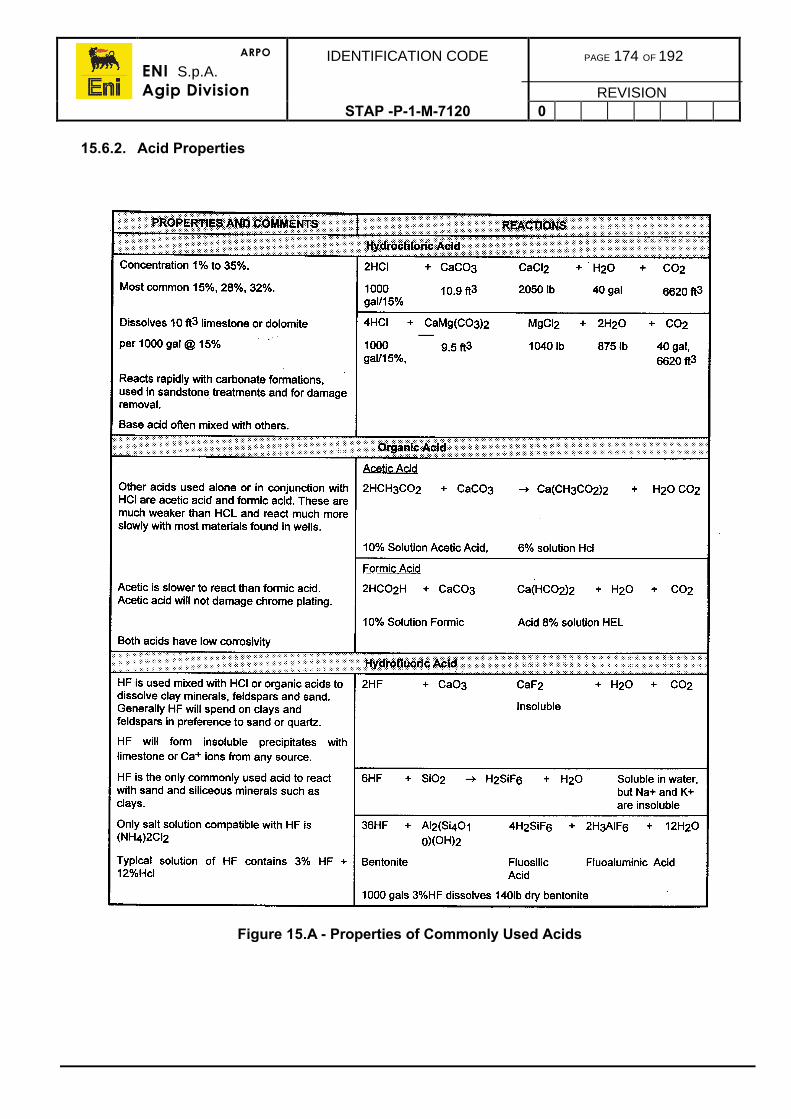
ARPO
ENI S.p.A.Agip Division
IDENTIFICATION CODE PAGE 174 OF 192
REVISIONSTAP -P-1-M-7120 0
15.6.2. Acid Properties
Figure 15.A - Properties of Commonly Used Acids
ARPO
ENI S.p.A.Agip Division
IDENTIFICATION CODE PAGE 175 OF 192
REVISIONSTAP -P-1-M-7120 0
15.7. ACID ADDITIVES
Several chemicals may be added to the acid in order to alter its chemical or physicalcharacteristics (Refer to the Drilling Fluids Manual). The most commonly used are:
Friction Reducer
These are added to reduce the frictional pressure drop while displacing acid into the well.They are particularly important when coiled tubing is being used, as the frictional pressuredrop can be considerable. They are added in concentrations varying from 1 to 4lb/1,000gals in order to achieve a reduction in friction pressure of 65-80%. Normally they are naturalor synthetic polymers, such as guar, cellulose, etc.
Diverting Agents
To ensure that the total interval of interest is to be properly stimulated it will be necessary tolimit the amount of acid penetrating any zones of high permeability and/or low pressure.This is done by adding a diverting agent to the treatment.
Diverting agents available are both mechanical and chemical in nature.
Mechanical means, such as ball sealers of high specific gravity are pumped at sufficientvelocity to plug off the perforations. They then drop off and fall into the sump when pumpingstops.
Chemical diverting agents bind together to form an impermeable skin across theperforations, or within the formation. They must be soluble in hydrocarbons or water to allowclean-up on back flushing.
Fluid Loss Additives
Fluid loss additives are mainly used in fracture treatments as an aid to extending thefractures by minimising bleed off of the treating fluid into the faces of the fracture. They maybe used for the same function as blocking agents.
Surfactants
Surfactants lower the surface tension of the acid solutions. They assist acid penetration intomicroscopic pores in tight formations, or in removing scale or cement particles from sandfaces. They aid acid penetration of oil films present in the pores, or formation surfaces soimproving contact. They also aid back flushing and return of spent acid during clean up bydecreasing the resistance of the formation to acid flow.
Retarders
Retarders are used to decrease the reaction rate to achieve increased penetration awayfrom the wellbore. This is done by using chemicals which deposit a film over the rock afterinitial acid contact, or through increased viscosity by using natural or artificial gums tothicken the acid.
ARPO
ENI S.p.A.Agip Division
IDENTIFICATION CODE PAGE 176 OF 192
REVISIONSTAP -P-1-M-7120 0
Demulsifiers
Demulsifiers are used to reduce the tendency of the acid to form an emulsion with oil withinthe formation. This is particularly important, as the formation of an emulsion may block thepores completely.
Corrosion Inhibitors
Corrosion inhibitors are used to minimise damage of the downhole tubulars by the acid.They can be complex organic substances which can inhibit both the anodic and cathodicreactions at the same time.
Iron Retention Additives
Iron hydroxides that form during a stimulation job may tend to deposit in both existing andnewly created flow channels. Iron sequestering additives, or a synergistic blend ofsequestering and pH control agents together may help prevent the precipitation of iron andother metallic salts or bases as the acid reacts. Sequestering is achieved by complexing theions of the iron with the additive so they remain in solution.
Additional Additives
Other additives which may be used are:
• Alcohol (aids clean up in water blocked gas zones)• Clay stabilisers• Scale inhibitor• Paraffin inhibitors.
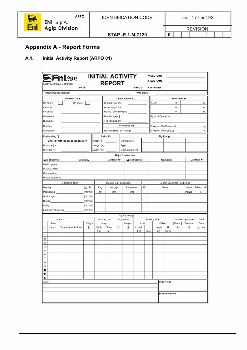
ARPO
ENI S.p.A.Agip Division
IDENTIFICATION CODE PAGE 177 OF 192
REVISIONSTAP -P-1-M-7120 0
Appendix A - Report Forms
A.1. Initial Activity Report (ARPO 01)
WELL NAME
FIELD NAME District/Affiliate Company
DATE: ARPO 01 Cost center
Permit/Concession N° Well Code
General Data Depth Above S.L . Joint venture
On shore Off shore Ground Level[m] AGIP: % %
Latitude: Water Depth [m] % %
Longitude Rotary Table Elev.[m] % %
Reference First Flange[m] Type of Operation
Rig Name Top housing [m]
Rig Type Reference Rig Program TD (Measured) [m]
Contractor Ref. Rig RKB - 1st Flange Program TD (Vertical) [m]
Rig Heading [°] Cellar Pit Rig Pump
Offset FROM the proposed location Depth [m] Manufacturer
Distance [m] Length [m] Type
Direction [°] Width [m]: Liner avaible [in]
Major Contractors
Type of Service Company Contract N° Type of Service Company Contract N°
Mud Logging
D. & C. Fluids
Cementation
Waste treatment
Operating Time Jack-up leg Penetration Supply Vessel for Positioning
Moving [gg:hh] Leg Air gap Penetration N° Name Horse Bollard pull
Positioning [hh:min] N° [m] [m] Power [t]
Anchorage [hh:min]
Rig-up [hh:min]
Delay [hh:min]
Lost-time Accidents [hh:min]
Rig Anchorage
Anchor Mooring Line Piggy Back Mooring Line Tension Operative Total
Bow Weight Length Weight Chain Cable [Tested] Tension Time
N° Angle Type & Manufacturer [t] Cable Chain N° [t] Length Ø Length Ø [t] [t] [hh:min]
[m] [m] [m] [mm] [m] [mm]
1
2
3
4
5
6
7
8
9
10
11
12
Note: Supervisor
Superintendent
INITIAL ACTIVITY REPORT
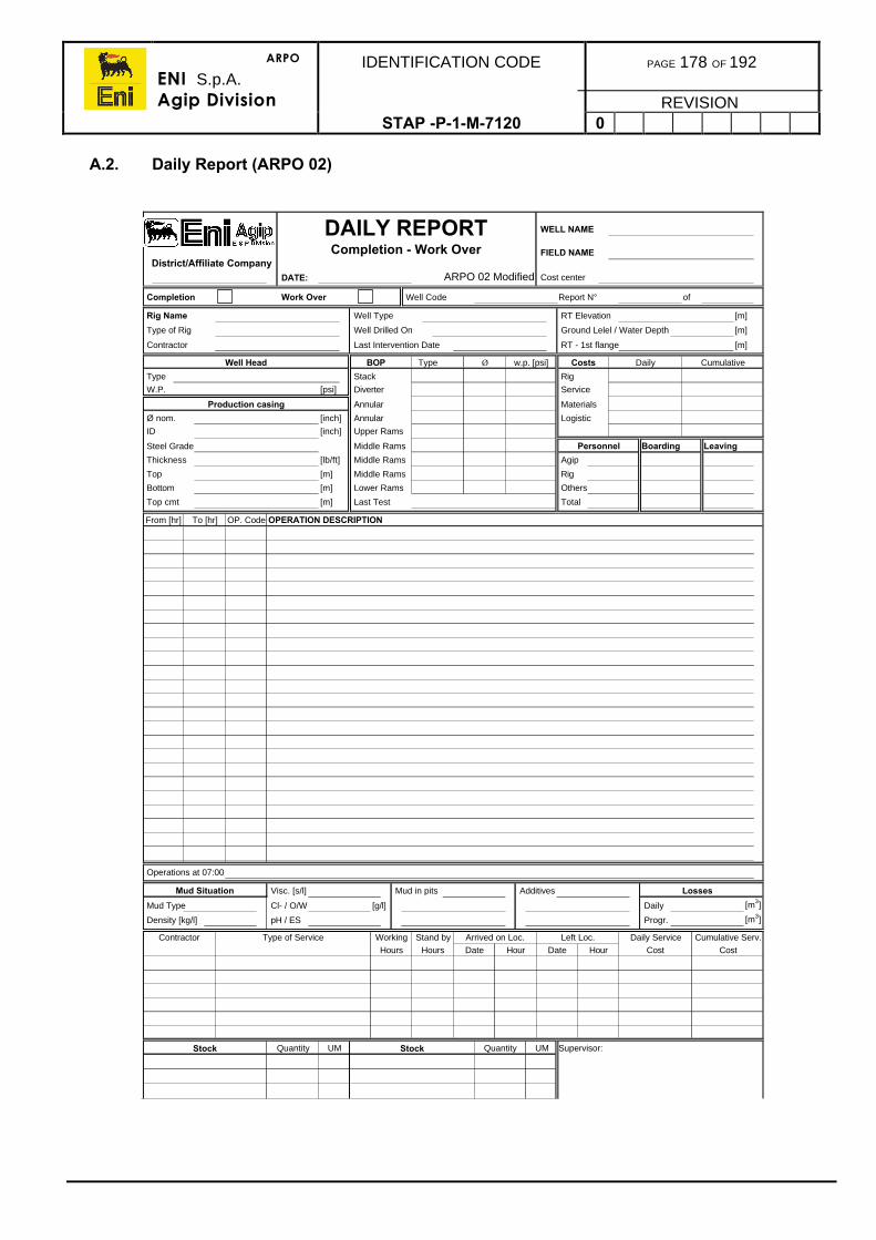
ARPO
ENI S.p.A.Agip Division
IDENTIFICATION CODE PAGE 178 OF 192
REVISIONSTAP -P-1-M-7120 0
A.2. Daily Report (ARPO 02)
WELL NAME
FIELD NAME District/Affiliate Company
DATE: ARPO 02 Modified Cost center
Completion Work Over Well Code Report N° of
Rig Name Well Type RT Elevation [m]
Type of Rig Well Drilled On Ground Lelel / Water Depth [m]
Contractor Last Intervention Date RT - 1st flange [m]
Well Head BOP Type Ø w.p. [psi] Costs Daily Cumulative
Type Stack Rig
W.P. [psi] Diverter Service
Production casing Annular Materials
Ø nom. [inch] Annular Logistic
ID [inch] Upper Rams
Steel Grade Middle Rams Personnel Boarding Leaving
Thickness [lb/ft] Middle Rams Agip
Top [m] Middle Rams Rig
Bottom [m] Lower Rams Others
Top cmt [m] Last Test Total
From [hr] To [hr] OP. Code OPERATION DESCRIPTION
Operations at 07:00
Mud Situation Visc. [s/l] Mud in pits Additives Losses
Mud Type Cl- / O/W [g/l] Daily [m3]
Density [kg/l] pH / ES Progr. [m3]
Contractor Type of Service Working Stand by Arrived on Loc. Left Loc. Daily Service Cumulative Serv.
Hours Hours Date Hour Date Hour Cost Cost
Stock Quantity UM Stock Quantity UM Supervisor:
DAILY REPORT Completion - Work Over
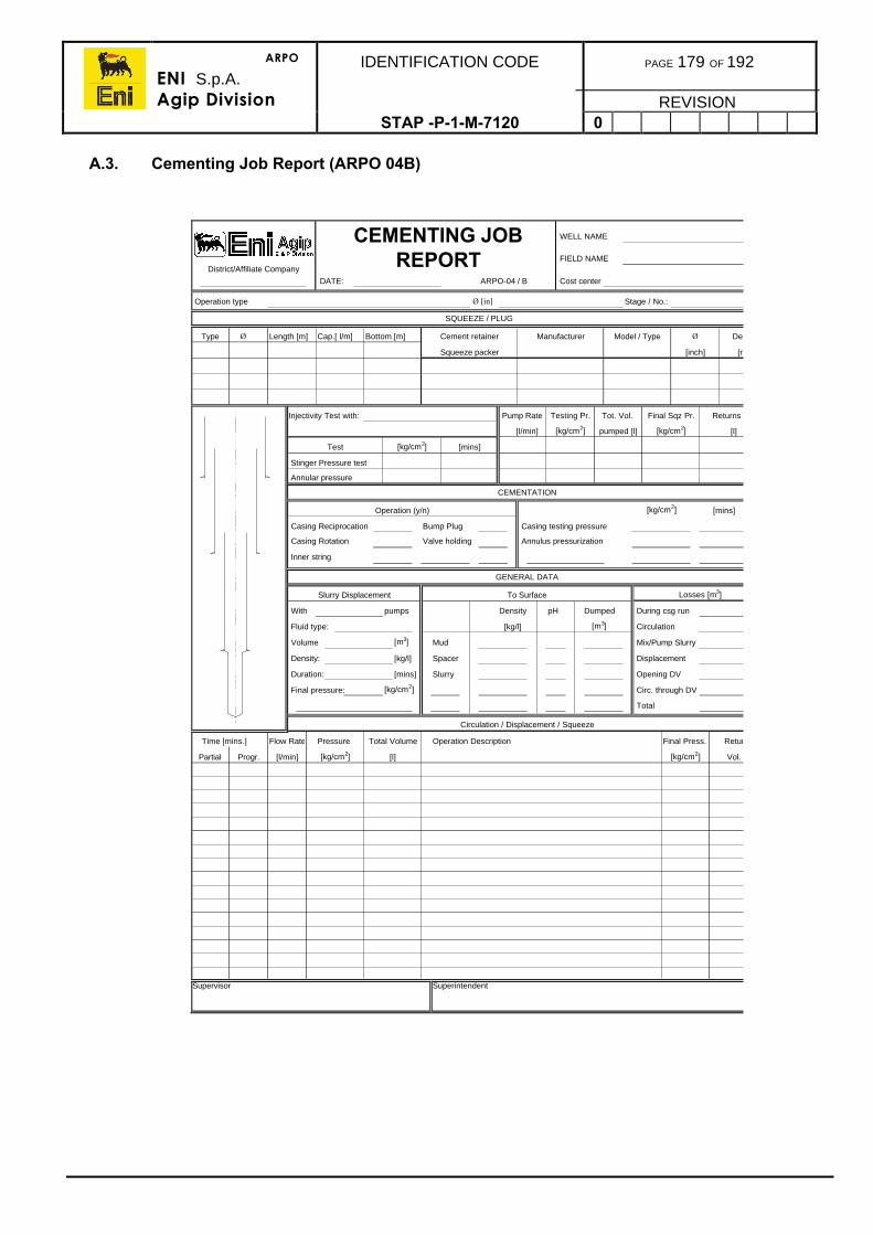
ARPO
ENI S.p.A.Agip Division
IDENTIFICATION CODE PAGE 179 OF 192
REVISIONSTAP -P-1-M-7120 0
A.3. Cementing Job Report (ARPO 04B)
WELL NAME
FIELD NAMEDistrict/Affiliate Company
DATE: ARPO-04 / B Cost center
Operation type Ø [in] Stage / No.:
SQUEEZE / PLUG
Type Ø Length [m] Cap.[ l/m] Bottom [m] Cement retainer Manufacturer Model / Type Ø Depth
Squeeze packer [inch] [m]
Injectivity Test with: Pump Rate Testing Pr. Tot. Vol. Final Sqz Pr. Returns Vol
[l/min] [kg/cm2] pumped [l] [kg/cm2] [l]
Test [kg/cm2] [mins]
Stinger Pressure test
Annular pressure
CEMENTATION
Operation (y/n) [kg/cm2] [mins]
Casing Reciprocation Bump Plug Casing testing pressure
Casing Rotation Valve holding Annulus pressurization
Inner string
GENERAL DATA
Slurry Displacement To Surface Losses [m3]
With pumps Density pH Dumped During csg run
Fluid type: [kg/l] [m3] Circulation
Volume [m3] Mud Mix/Pump Slurry
Density: [kg/l] Spacer Displacement
Duration: [mins] Slurry Opening DV
Final pressure: [kg/cm2] Circ. through DV
Total
Circulation / Displacement / Squeeze
Time [mins.] Flow Rate Pressure Total Volume Operation Description Final Press. Returns
Partial Progr. [l/min] [kg/cm2] [l] [kg/cm2] Vol. [l]
Supervisor Superintendent
CEMENTING JOB REPORT
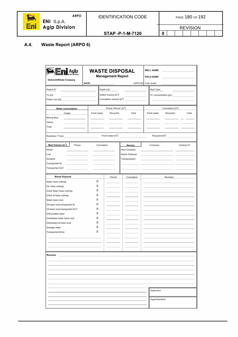
ARPO
ENI S.p.A.Agip Division
IDENTIFICATION CODE PAGE 180 OF 192
REVISIONSTAP -P-1-M-7120 0
A.4. Waste Report (ARPO 6)
WELL NAME
FIELD NAMEDistrict/Affiliate Company
DATE: ARPO-06 Cost center
Report N° Depth (m) Mud Type From [m] Interval Drilled (m) Density (kg/l)
To [m] Drilled Volume [m3] Cl- concentration (g/l )
Phase size [in] Cumulative volume [m3]
Water consumption Phase /Period [m3] Cumulative [m3]
Usage Fresh water Recycled Total Fresh water Recycled Total
Mixing Mud
Others
Total
Readings / Truck Fresh water [m3] Recycled [m3]
Mud Volume [m3] Phase Cumulative Service Company Contract N°
Mixed Mud Company
Lost Waste Disposal
Dumped Transportation
Transported IN
Transported OUT
Waste Disposal Period Cumulative Remarks
Water base cuttings [t]
Oil base cuttings [t]
Dried Water base cuttings [t]
Dried oil base cuttings [t]
Water base mud [t]
Oil base mud transported IN [t]
Oil base mud transported OUT [t]
Drill potable water [t]
Dehidrated water base mud [t]
Dehidrated oil base mud [t]
Sewage water [t]
Transported Brine [t]
Remarks
Supervisor
Superintendent
WASTE DISPOSALManagement Report
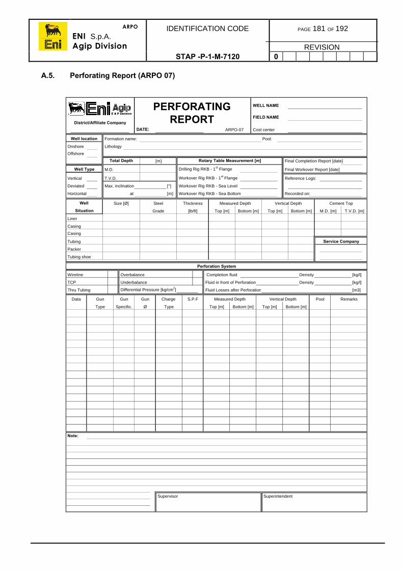
ARPO
ENI S.p.A.Agip Division
IDENTIFICATION CODE PAGE 181 OF 192
REVISIONSTAP -P-1-M-7120 0
A.5. Perforating Report (ARPO 07)
WELL NAME
FIELD NAMEDistrict/Affiliate Company
DATE: ARPO-07 Cost center
Well location Formation name: Pool:
Onshore Lithology
Offshore
Total Depth [m] Rotary Table Measurement [m] Final Completion Report [date]
Well Type M.D. Drilling Rig RKB - 1st Flange Final Workover Report [date]
Vertical T.V.D. Workover Rig RKB - 1st Flange Reference Logs:
Deviated Max. inclination [°] Workover Rig RKB - Sea Level
Horizontal at [m] Workover Rig RKB - Sea Bottom Recorded on:
Well Size [Ø] Steel Thickness Measured Depth Vertical Depth Cement Top
Situation Grade [lb/ft] Top [m] Bottom [m] Top [m] Bottom [m] M.D. [m] T.V.D. [m]
Liner
Casing
Casing
Tubing Service Company
Packer
Tubing shoe
Perforation System
Wireline Overbalance Completion fluid Density [kg/l]
TCP Underbalance Fluid in front of Perforation Density [kg/l]
Thru Tubing Differential Pressure [kg/cm2] Fluid Losses after Perforation [m3]
Data Gun Gun Gun Charge S.P.F Measured Depth Vertical Depth Pool Remarks
Type Specific. Ø Type Top [m] Bottom [m] Top [m] Bottom [m]
Note:
Supervisor Superintendent
PERFORATING REPORT
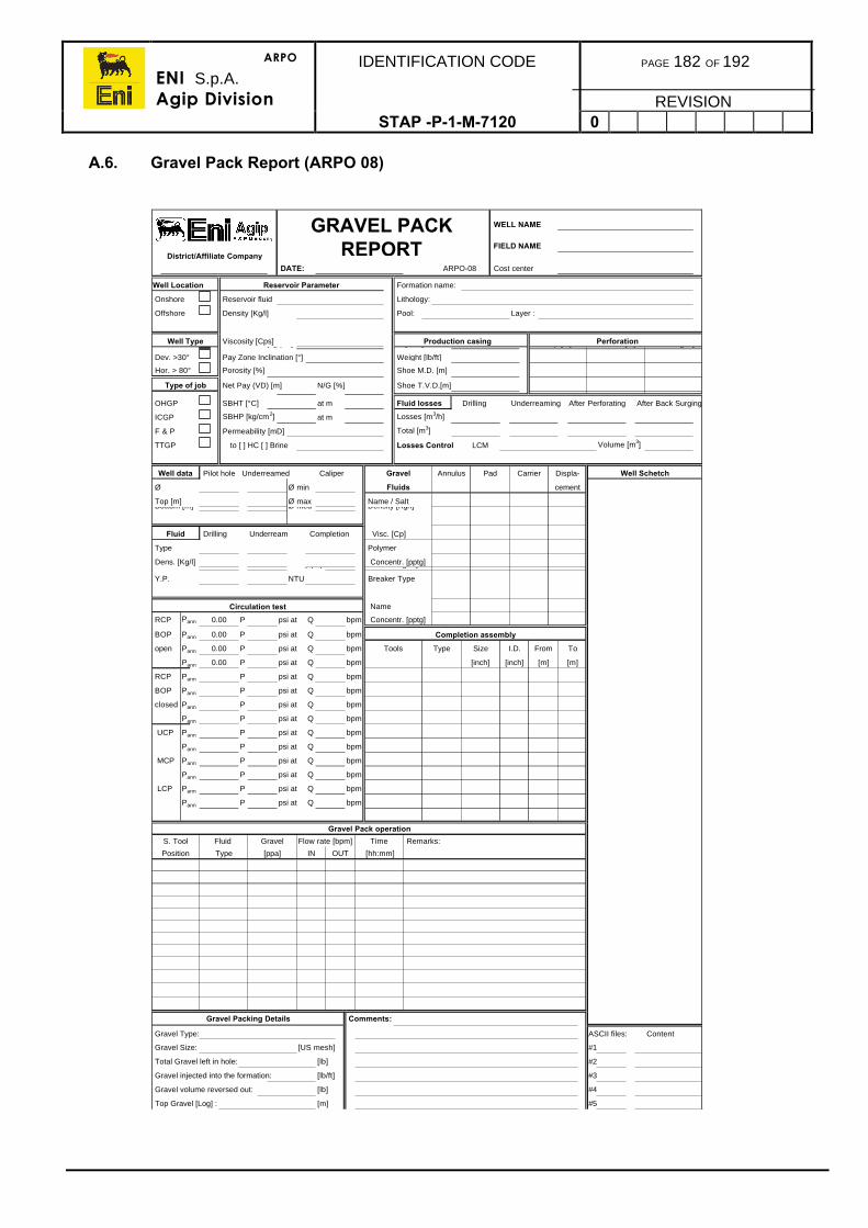
ARPO
ENI S.p.A.Agip Division
IDENTIFICATION CODE PAGE 182 OF 192
REVISIONSTAP -P-1-M-7120 0
A.6. Gravel Pack Report (ARPO 08)
WELL NAME
FIELD NAMEDistrict/Affiliate Company
DATE: ARPO-08 Cost center
Well Location Reservoir Parameter Formation name:
Onshore Reservoir fluid Lithology:
Offshore Density [Kg/l] Pool: Layer :
Well Type Viscosity [Cps] Production casing Perforation Vert. < 30° Water Salinity [ppm] Ø [inch] Top [m] Bottom [m] UB/OB [psi]
Dev. >30° Pay Zone Inclination [°] Weight [lb/ft]
Hor. > 80° Porosity [%] Shoe M.D. [m]
Type of job Net Pay (VD) [m] N/G [%] Shoe T.V.D.[m]
OHGP SBHT [°C] at m Fluid losses Drilling Underreaming After Perforating After Back Surging
ICGP SBHP [kg/cm2] at m Losses [m3/h]
F & P Permeability [mD] Total [m3]
TTGP to [ ] HC [ ] Brine Losses Control LCM Volume [m3]
Well data Pilot hole Underreamed Caliper Gravel Annulus Pad Carrier Displa- Well Schetch
Ø Ø min Fluids cement
Top [m] Ø max Name / Salt Bottom [m] Ø med Density [Kg/l]
Fluid Drilling Underream Completion Visc. [Cp]
Type Polymer
Dens. [Kg/l] Concentr. [pptg] P.V. Visc.[cps] Filtration [µm]
Y.P. NTU Breaker Type
Circulation test Name
RCP Pann 0.00 P psi at Q bpm Concentr. [pptg]
BOP Pann 0.00 P psi at Q bpm Completion assembly
open Pann 0.00 P psi at Q bpm Tools Type Size I.D. From To
Pann 0.00 P psi at Q bpm [inch] [inch] [m] [m]
RCP Pann P psi at Q bpm
BOP Pann P psi at Q bpm
closed Pann P psi at Q bpm
Pann P psi at Q bpm
UCP Pann P psi at Q bpm
Pann P psi at Q bpm
MCP Pann P psi at Q bpm
Pann P psi at Q bpm
LCP Pann P psi at Q bpm
Pann P psi at Q bpm
Gravel Pack operation
S. Tool Fluid Gravel Flow rate [bpm] Time Remarks:
Position Type [ppa] IN OUT [hh:mm]
Gravel Packing Details Comments:
Gravel Type: ASCII files: Content
Gravel Size: [US mesh] #1
Total Gravel left in hole: [lb] #2
Gravel injected into the formation: [lb/ft] #3
Gravel volume reversed out: [lb] #4
Top Gravel [Log] : [m] #5
PERFORATING REPORT
GRAVEL PACK REPORT
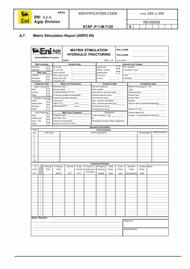
ARPO
ENI S.p.A.Agip Division
IDENTIFICATION CODE PAGE 183 OF 192
REVISIONSTAP -P-1-M-7120 0
A.7. Matrix Stimulation Report (ARPO 09)
WELL NAME
FIELD NAMEDistrict/Affiliate Company
DATE: ARPO - 09 Cost center
Well Location General Data Interval to be Treated Onshore M.D. [m] Open hole Tot. net perf.:
Offshore T.V.D. [m] Perfor. interval Formation name:
Well Type Open hole Ø Slotted liner Vertical Prod. casing / liner Ø From [m] Pool:
Deviated Shoe M.D. [m] To [m] Lithology: Horizontal Top liner [m]
Treatment Type Reservoir Parameters Treatment Data Completion DataMatrix stimulation Reservoir fluid Service Company Bottom hole gauge [Y / N]
Acid Density [Kg/l] HHP avaible Type
Solvent Gradient [Kg/cm2/10 m.] Initial Shut-in pressure [psi] Wellhead type
Other Fracturing gradient [calculated] Annulus pressure [psi] Packer type
Hydraulic Fracturing Fracturing gradient [tested] Pressure test [psi] Packer fluid
Foam Porosity % Max. injection rate [bpm] Density
Water base SBHT [°C] at m Max. injection pressure [psi] Fluid in well at operation beginning
Oil base SBHP [kg/cm2] at m Pumping time [min]
Other Pumping time [min] String O.D. [in]
Acid Fracturing Main Frac Treatment Equipment String capacity [l]
Acid Proppant type: Coiled Tubing [Y / N] Packer - Top perforation Volume [l]
Gelled acid API Mesh Size Ø
Acid + Gel Amount of Propant [t] Stimulation vessel / Other equipment
Other Total Frac Fluid Vol. [m3]
Operation DescriptionFluid Fluid ScheduleRef. Fluid Type Fluid Composition Density [kg/l] Mixed Volume [m3]
1
2
3
4
5
6
7
8
910
Pumping Parameter N° Starting Pumping Volume Progr. Progr.Vol. Proppant Initial Final Injection Casing Notes
Fluid Time Rate Volume Entering in Concentr. Press. Press. Index Press.
Ref. [bbl/1'] [m3] [m3]Formation
[lb/gal] [psi] [psi] [bbl/day/psi] [psi]
Notes / Remarks:
Supervisor
Superintendent
Inje
cted
C
ircul
ated
MATRIX STIMULATION HYDRAULIC FRACTURING
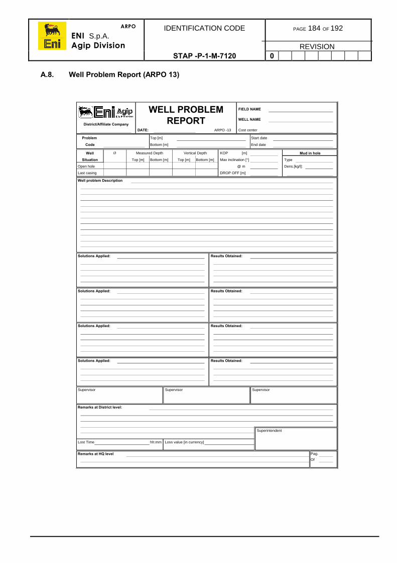
ARPO
ENI S.p.A.Agip Division
IDENTIFICATION CODE PAGE 184 OF 192
REVISIONSTAP -P-1-M-7120 0
A.8. Well Problem Report (ARPO 13)
FIELD NAME
WELL NAMEDistrict/Affiliate Company
DATE: ARPO -13 Cost center
Problem Top [m] Start date
Code Bottom [m] End date
Well Ø Measured Depth Vertical Depth KOP [m] Mud in hole
Situation Top [m] Bottom [m] Top [m] Bottom [m] Max inclination [°] Type
Open hole @ m Dens.[kg/l]:
Last casing DROP OFF [m]
Well problem Description
Solutions Applied: Results Obtained:
Solutions Applied: Results Obtained:
Solutions Applied: Results Obtained:
Solutions Applied: Results Obtained:
Supervisor Supervisor Supervisor
Remarks at District level:
Superintendent
Lost Time hh:mm Loss value [in currency]
Remarks at HQ level Pag.
Of
WELL PROBLEM REPORT
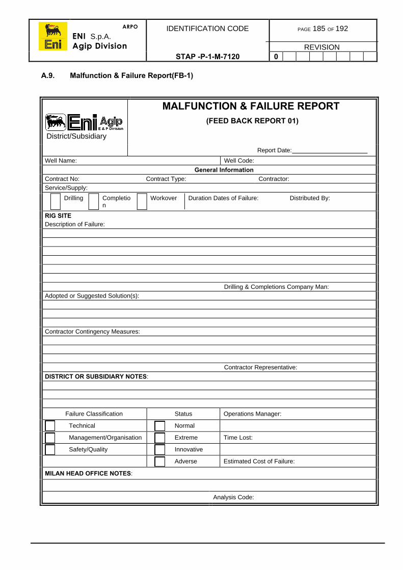
ARPO
ENI S.p.A.Agip Division
IDENTIFICATION CODE PAGE 185 OF 192
REVISIONSTAP -P-1-M-7120 0
A.9. Malfunction & Failure Report(FB-1)
MALFUNCTION & FAILURE REPORT(FEED BACK REPORT 01)
Report Date:
Well Name: Well Code:
General InformationContract No: Contract Type: Contractor:
Service/Supply:
Drilling Completion
Workover Duration Dates of Failure: Distributed By:
RIG SITEDescription of Failure:
Drilling & Completions Company Man:
Adopted or Suggested Solution(s):
Contractor Contingency Measures:
Contractor Representative:
DISTRICT OR SUBSIDIARY NOTES:
Failure Classification Status Operations Manager:
Technical Normal
Management/Organisation Extreme Time Lost:
Safety/Quality Innovative
Adverse Estimated Cost of Failure:
MILAN HEAD OFFICE NOTES:
Analysis Code:
District/Subsidiary

ARPO
ENI S.p.A.Agip Division
IDENTIFICATION CODE PAGE 186 OF 192
REVISIONSTAP -P-1-M-7120 0
A.10. Contractor Evaluation (FB-2)
CONTRACTOR EVALUATION(FEED BACK REPORT 02)
Report Date:
Well Name: Well Code:General Information
Contract No.: Contract Type: Contractor:Service/Supply: Distributed By:
R1 Technical RequirementsFB_01 REPORT REFERENCES
FB Report No.: Time Lost (Hr.Min): Economic Cost (£M):Category Evaluation Score (0-9)
Suitability of Equipment and MaterialsCompliance of Equipment and Materials to theContractAdequacy of PersonnelMeeting with Operational Programme RequirementsMeeting with Contract Operation TimingsEquipment Condition/Maintenance
R2 Management and Organisational RequirementsFB_01 REPORT REFERENCES
FB Report No.: Time Lost (Hr.Min): Economic Cost (£M):Category Evaluation Score (0-9)
Availability of Equipment and MaterialsTechnical and Operational Support to OperationsCapability and Promptness to Operational Requests
R3 Safety and Quality Assurance RequirementsFB_01 REPORT REFERENCES
FB Report No.: Time Lost (Hr.Min): Economic Cost (£M):Category Evaluation Score (0-9)
Meeting with the Contract Agreement DSSAvailability and Validity of Requested CertificatesMeeting with Contract Quality Assurance Terms
Event Support DocumentationType of
Document:Subject: Issued By: Date:
Notes:
Failure Status Operations Manager Drilling & Completions ManagerNormal Extreme Adverse Innovative
District/Subsidiary
ARPO
ENI S.p.A.Agip Division
IDENTIFICATION CODE PAGE 187 OF 192
REVISIONSTAP -P-1-M-7120 0
Appendix B - ABBREVIATIONS
AC/DC Alternate Current, Direct CurrentAHTS Anchor Handling Towing SupplyAPI American Petroleum InstituteBG Background gasBHA Bottom Hole AssemblyBHP Bottom Hole PressureBHT Bottom Hole temperatureBJ Blast JointBMT Blue Methylene TestBOP Blow Out PreventerBPD Barrel Per DayBPM Barrels Per MinuteBPV Back Pressure ValveBSW Base Sediment and WaterBUR Build Up RateBWOC By Weight Of CementBWOW By Weight Of WaterC/L Control LineCBL Cement Bond LogCCD Centre to Centre DistanceCCL Casing Collar LocatorCDP Common Depth PointCET Cement Evaluation ToolCGR Condensate Gas RatioCMT CementCP Conductor PipeCR Cement RetainerCRA Corrosion Resistant AlloyCSG CasingC/T Coiled TubingCW Current WellDC Drill CollarDE Diatomaceous EarthDHM Down Hole MotorDHSV Down Hole Safety ValveDIF Drill in FluidDLP Dog Leg PotentialDLS Dog Leg SeverityD&CM Drilling & Completion ManagerDOB Diesel Oil BentoniteDOBC Diesel Oil Bentonite CementDOR Drop Off RateDP Drill PipeDPHOT Drill Pipe Hang off ToolDRLG Drilling
ARPO
ENI S.p.A.Agip Division
IDENTIFICATION CODE PAGE 188 OF 192
REVISIONSTAP -P-1-M-7120 0
DST Drill Stem TestDV DV CollarE/L Electric LineECD Equivalent Circulation DensityECP External Casing PackerEMS Electronic Multi ShotEMW Equivalent Mud WeightEOC End Of CurvatureEP External PressureESD Electric Shut-Down SystemESP Electrical Submersible PumpETA Expected Arrival TimeETU Endless Tubing UnitFBHP Flowing Bottom Hole PressureFBHT Flowing Bottom Hole TemperatureFC Flow CouplingFINS Ferranti International Navigation SystemFPI/BO Free Point Indicator / Back OffFTHP Flowing Tubing Head PressureFTHT Flowing Tubing Head TemperatureGCT Guidance Continuous ToolGLR Gas Liquid RatioGLS Guidelineless Landing StructureGMS Gyro Multi ShotGOC Gas Oil ContactGOR Gas Oil RatioGP Gravel PackGPM Gallon (US) per MinuteGPS Global Positioning SystemGR Gamma RayGRA Guidelines Re-Entry AssemblyGSS Gyro Single ShotHAZOP Hazard and OperabilityHDT High Resolution DipmeterHHP Hydraulic HorsepowerHO Hole OpenerHP/HT High Pressure - High TemperatureHSI Horsepower per Square FootHW/HWDP Heavy Weight Drill PipeIADC International Drilling ContractorIBOP Inside Blow Out PreventerICGP Inside Casing Gravel PackingID Inside DiameterIFR Imposta Fabbricazione RidottaIP Internal PressureIPR Inflow Performance RelationshipJAM Joint Make-up Torque Analyser
ARPO
ENI S.p.A.Agip Division
IDENTIFICATION CODE PAGE 189 OF 192
REVISIONSTAP -P-1-M-7120 0
KMW Kill Mud WeightKOP Kick Off PointL/D Lay DownL/S Long StringLAT Lowest Astronomical TideLC 50 Lethal Concentration 50%LCDT Last Crystal to Dissolve oCLCM Lost Circulation MaterialsLCP Lower Circulation Position (GP)LEL Lower Explosive LimitLMRP Low Marine Riser PackageLN Landing NippleLOT Leak Off TestLQC Log Quality ControlLTA Lost Time AccidentLTT Lower Tell Table (GP)LWD Log While DrillingM/D Martin DeckerM/U Make UpMAASP Max Allowable Annular Surface PressureMD Measured DepthMLH Mudline HangerMLS Mudline SuspensionMMS Magnetic Multi ShotMODU Mobile Offshore Drilling UnitMOP Margin of OverpullMPI Magnetic Particle InspectionMSCL Modular Single Completion LandMSL Mean Sea LevelMSS Magnetic Single ShotMUT Make up TorqueMW Mud WeightMWD Measurement While DrillingN/D Nipple DownN/U Nipple UpNACE National Association of Corrosion EngineersNB Near Bit StabiliserNDT Non Destructive TestNMDC Non Magnetic Drill CollarNSG North Seeking GyroNTU Nephelometric Turbidity UnitOBM Oil Base MudOD Outside DiameterOEDP Open End Drill PipeOH Open HoleOHGP Open Hole Gravel PackingOIM Offshore Installation Manager
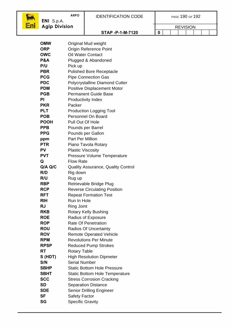
ARPO
ENI S.p.A.Agip Division
IDENTIFICATION CODE PAGE 190 OF 192
REVISIONSTAP -P-1-M-7120 0
OMW Original Mud weightORP Origin Reference PointOWC Oil Water ContactP&A Plugged & AbandonedP/U Pick upPBR Polished Bore ReceptaclePCG Pipe Connection GasPDC Polycrystalline Diamond CutterPDM Positive Displacement MotorPGB Permanent Guide BasePI Productivity IndexPKR PackerPLT Production Logging ToolPOB Personnel On BoardPOOH Pull Out Of HolePPB Pounds per BarrelPPG Pounds per Gallonppm Part Per MillionPTR Piano Tavola RotaryPV Plastic ViscosityPVT Pressure Volume TemperatureQ Flow RateQ/A Q/C Quality Assurance, Quality ControlR/D Rig downR/U Rug upRBP Retrievable Bridge PlugRCP Reverse Circulating PositionRFT Repeat Formation TestRIH Run In HoleRJ Ring JointRKB Rotary Kelly BushingROE Radius of ExposureROP Rate Of PenetrationROU Radios Of UncertaintyROV Remote Operated VehicleRPM Revolutions Per MinuteRPSP Reduced Pump StrokesRT Rotary TableS (HDT) High Resolution DipmeterS/N Serial NumberSBHP Static Bottom Hole PressureSBHT Static Bottom Hole TemperatureSCC Stress Corrosion CrackingSD Separation DistanceSDE Senior Drilling EngineerSF Safety FactorSG Specific Gravity
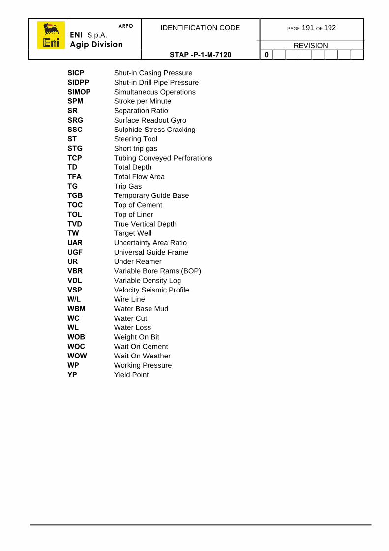
ARPO
ENI S.p.A.Agip Division
IDENTIFICATION CODE PAGE 191 OF 192
REVISIONSTAP -P-1-M-7120 0
SICP Shut-in Casing PressureSIDPP Shut-in Drill Pipe PressureSIMOP Simultaneous OperationsSPM Stroke per MinuteSR Separation RatioSRG Surface Readout GyroSSC Sulphide Stress CrackingST Steering ToolSTG Short trip gasTCP Tubing Conveyed PerforationsTD Total DepthTFA Total Flow AreaTG Trip GasTGB Temporary Guide BaseTOC Top of CementTOL Top of LinerTVD True Vertical DepthTW Target WellUAR Uncertainty Area RatioUGF Universal Guide FrameUR Under ReamerVBR Variable Bore Rams (BOP)VDL Variable Density LogVSP Velocity Seismic ProfileW/L Wire LineWBM Water Base MudWC Water CutWL Water LossWOB Weight On BitWOC Wait On CementWOW Wait On WeatherWP Working PressureYP Yield Point

ARPO
ENI S.p.A.Agip Division
IDENTIFICATION CODE PAGE 192 OF 192
REVISIONSTAP -P-1-M-7120 0
Appendix C - BIBLIOGRAPHY
Document: STAP Number
Completion Design Manual STAP-P-1-7100
Drilling Procedures Manual STAP-P-1-6140
Drilling Fluids Manual STAP I N 6051
Well Control Policy Manual STAP-P-1-6150
Well Test Manual STAP-P-1-7130
Wireline Procedures Manual STAP-P-1-7110
Other
API Specification No 811-05CT5
Related Documents