PROCEDURES FOR MINIMIZING DRILLING AND COMPLETION DAMAGE IN HORIZONTAL WELLS - LABORATORY AND FIELD CASE STUDIES IN THE VIRGINIA HILLS BELLOY SAND By D. Brant Bennion, Hycal Energy Research laboratories Ltd. Wayne Jones - Shell CanadaLtd. Paper to be presented at the SPE/CIM 4th Annual One Day Conference on Horizontal Wells, Calgary, Canada, November 22,1994. ABsmACT INTRODUCTION Horizontal wells are particularly susceptible to fonnation damage due to a combination of phenomena ranging from extended exposure time to anisotropic flow phenomena associated with vertical to horizontal permeability contrasts. A proper understanding of the potential interaction of proposed drilling and completion fluids with the rock matrix under prevailing conditions of overbalance or underbalance pressure, which are to be associated with horizontal drilling, are essential to optimize the proposed drilling and completion program for a given horizontal well and a given lithology. This paper outlines current state-of-the-art laboratory evaluation procedures used to evaluate drilling and completion fluids for both overbalanced and underbalanced drilling procedures In both gas and 011 reservoirs In clastic and carbonate horizons. A case history illustrating the application of this technology to a horizontal completion by Shell Canada In the Belloy sand In the Virginia Hills area Is documented. After laboratory design test procedures were completed. the well was successfully drilled, cased and perforated and produced 420 m3/day (2600 bbl/day) of clean 011 at a 1 MPa drawdown pressure with rate being limited by ESP and surface limitations, rather than well productivity. For comparative purposes, vertical wells in the same area produce 350 m3/day at high water cuts and at over 500% greater drawdown pressures. Horizontal drilling is being utilized in an ever increasing fashionto exploit reservoirs exhibiting thin pay zones, problems with water or gas coning,to obtain greater reservoirexposureand to maximize the productivepotentialof naturally fractured reservoirs. Reductions in the productivity of these horizontal wells due to improperly or inadequately designed drilling, completion or workover programs is a frequent occurrence. This paper documents laboratory techniques which are currently being used to evaluatedrilling fluid performance for horizontal well applications and presents a combined laboratory-field case study to illustrate the application of this technology. INVASIVE FORMATION DAMAGE Formation damage can be described as any phenomenon induced by the drilling, completion or stimulation process or by regular operations resulting In a permanent reduction in the productMty of a producingoil or gas well. Invasive fonnation damage can occur during drilling by the introduction of: a) b) c) d) Foreign potentially incompatible fluids into the formation. Naturalor artificial solids. Extraneous immiscible phases. Physicalmechanical damage.

Welcome message from author
This document is posted to help you gain knowledge. Please leave a comment to let me know what you think about it! Share it to your friends and learn new things together.
Transcript

PROCEDURES FOR MINIMIZING DRILLINGAND COMPLETION DAMAGE IN HORIZONTAL WELLS -
LABORATORY AND FIELD CASE STUDIES INTHE VIRGINIA HILLS BELLOY SAND
By
D. Brant Bennion, Hycal Energy Research laboratories Ltd.Wayne Jones - Shell Canada Ltd.
Paper to be presented at the SPE/CIM 4th Annual One Day Conference on HorizontalWells, Calgary, Canada, November 22,1994.
ABsmACT INTRODUCTION
Horizontal wells are particularly susceptible tofonnation damage due to a combination ofphenomena ranging from extended exposuretime to anisotropic flow phenomena associatedwith vertical to horizontal permeability contrasts.A proper understanding of the potentialinteraction of proposed drilling and completionfluids with the rock matrix under prevailingconditions of overbalance or underbalancepressure, which are to be associated withhorizontal drilling, are essential to optimize theproposed drilling and completion program for agiven horizontal well and a given lithology. Thispaper outlines current state-of-the-art laboratoryevaluation procedures used to evaluate drillingand completion fluids for both overbalanced andunderbalanced drilling procedures In both gasand 011 reservoirs In clastic and carbonatehorizons. A case history illustrating theapplication of this technology to a horizontalcompletion by Shell Canada In the Belloy sand Inthe Virginia Hills area Is documented. Afterlaboratory design test procedures werecompleted. the well was successfully drilled,cased and perforated and produced 420 m3/day(2600 bbl/day) of clean 011 at a 1 MPa drawdownpressure with rate being limited by ESP andsurface limitations, rather than well productivity.For comparative purposes, vertical wells in thesame area produce 350 m3/day at high watercuts and at over 500% greater drawdownpressures.
Horizontal drilling is being utilized in an everincreasing fashion to exploit reservoirs exhibitingthin pay zones, problems with water or gasconing, to obtain greater reservoir exposure andto maximize the productive potential of naturallyfractured reservoirs. Reductions in theproductivity of these horizontal wells due toimproperly or inadequately designed drilling,completion or workover programs is a frequentoccurrence. This paper documents laboratorytechniques which are currently being used toevaluate drilling fluid performance for horizontalwell applications and presents a combinedlaboratory-field case study to illustrate theapplication of this technology.
INVASIVE FORMATION DAMAGE
Formation damage can be described as anyphenomenon induced by the drilling, completionor stimulation process or by regular operationsresulting In a permanent reduction in theproductMty of a producing oil or gas well.
Invasive fonnation damage can occur duringdrilling by the introduction of:
a)
b)c)d)
Foreign potentially incompatible fluids intothe formation.Natural or artificial solids.Extraneous immiscible phases.Physical mechanical damage.

FORMATION DAMAGE IN HORIZONTAL vsVERTICAL WELLS
1.
23.4.5
A detailed discussion of mechanisms offormation damage in horizontal wells has beenpresented in the literature.' Formation damagetends to be more significant in horizontal vsvertical wells for a number of reasons, some ofthese being:
6.
7.
Fluid-fluid incompatibilitiesRock-Fluid IncompatibilitiesSolids InvasionPhase trapping and blockingChemical adsorption and wettabilityalterationRnes migrationBiological activity (caused by bacterialagents introduced during the drillingprocess)
Longer fluid exposure time to theformation during drilling and greaterpotential depth of Invasion in situationswhere sustained fluid and solids losses tothe formation are apparent.
1Detailed discussion of these specific damage
mechanisms has been elucidated on in other
papers.2
VIRGINIA HILLS TEST PROGRAMOBJECTIVESThe majority of horizontal wells remain as
open hole or slotted liner completions.Therefore, shallow damage, which wouldnormally be perforated through in a typicalvertical completion, may remain as animpermeable or low permeability barrier tooil or gas flow.
The objectives of the Virginia Hills Belloy labtesting program were to compare three differentfluid systems, a conventional water-based mud,an invert mud system and a water-based oilsoluble resin system with respect to invasivecharacter and degree of permanent permeabilityimpainnent. An adjunct portion of the testprogram was to examine selected stimulationtechniques to remove the fonnation damagepresent.
Drawdowns applied in many horizontalwells result in selective cleanup of a smallportion of the total exposed available flowarea, causing the majority of theproduction from a relatively small fractionof the exposed wellbore face.
3
EXPERIMENTAL EQUIPMENT
Agure 1 provides a schematic of theexperimental equipment utilized to conduct theVirginia Hills displacement tests. The corematerial is mounted in a triaxially loadedconfining cell capable of restressing the rock tonet overburden conditions (17395 kPa). Thecore cell is contained in a temperature controlledoven to maintain the sample at the correctbottomhole temperature (70°C). A controllingbackpressure regulator can be used to maintainthe intemal pore space of the sample at fullreservoir conditions of pressure, If desired.
Selective stimulation in wells where slottedliners are in place is inefficient. Extensivestimulation of any horizontal section isgenerally difficult and expensive incomparison to a vertical well, and hencemany stimulation programs are ineffectivedue to cost and/or time limitations.
4
Anisotropic flow phenomena due to Kv/Khpermeability contrasts.
5
COMMON DAMAGE MECHANISMS (DRILLING)
Baseline and post test permeabilitymeasurements are conducted by displacingVirginia Hills unoxldlzed produced crude oilthrough the sample at a known displacement rateusing a variable rate pulsation-free electronicallycontrolled positive displacement pump. Pressuredifferential across the sample is measuredprecisely using an electronic capacitance
The drilling process represents one of the mostpotentially damaging phases in the horizontal wellImplementation process. Although a variety ofdamage mechanisms exist, certain types ofdamage tend to be more severe based upon thespecific type of reservoir and fluid system underconsideration. Common damage mechanismsassociated with the drilling process include:

transducer interfaced to a digital terminal. Aknowledge of the differential pressure and flowrate, combined with known physical dimensionsof the test samples and viscosity of the displacedVirginia Hills oil allows ready computation of thesample permeability.
dynamically displaced with unoxidized reservoircrude oil which had been sampled and stored inan oxygen-free environment. Crude oil wasdisplaced at the reservoir temperature of 700C fora continuous period of six weeks to allow anequilibrium wetting condition to be established.Once the wettability restoration process had beencompleted individual samples were subjected tosessile contact angle measurements to obtain anapproximate evaluation of sample wettability.The results of these contact angle measurementsare summarized in Table 2. Contact anglesvarying from 39-4~ indicating moderately waterwet behavior for the Virginia Hills matrix wereobtained based upon the results of thesemeasurements.
For the drilling fluid evaluation phase of thetest, whole mud (containing added solids) iscontinuously circulated past the end of the coreusing a specially designed large volumethroughput head and a constant pressure positivedisplacement pump and source to allowcirculation of the mud at a constant net specifiedoverbalance pressure to simulate anoverbalanced drilling operation in the field. Theapparatus can also be modified to simulatebalanced or underbalanced drilling operations(Figure 2) but, due to the sour nature of theproduced Virginia Hills fluids and economic andoperational considerations, underbalanced drillingwas not considered for this particular application.
EXPERIMENTAL FLUID PROCUREMENT
Three different test muds were utilized in theVirginia Hills experimental test programs. Thesewere a water-based Belloy test mud, a 90/10invert system and a oil soluble resin system. TheBelloy test mud and invert system contained 55kg/m3 of 325 mesh calcium carbonate and 33kg/m3 of .0. grind calcium carbonate. All of themud systems tested contained 75 kg/m3 of lessthan 20 micron diameter Virginia Hills formationsolids. These fonnation solids were prepared bypulverizing samples of representative Virginia Hillcore material and sieving the samples in order toobtain a bell shaped particulate distribution witha medium size of approximately 5 - 8 micronsand maximum size of 20 microns for inclusion inthe mud system. These solids were added tosimulate the drill solids not removed by the solidscontrol equipment present on surface during thedrilling operation.
EXPERIMENTAL PROCEDURE
Core Procurement and Wettability Restoration
Core samples 3.81 cm in diameter were drilledfrom selected intervals of Virginia Hills area wells11-30-63-13 W5M, 6-30-63-13 W5M and 13-29-63-13 W5M using synthetic formation brine as alubricating fluid. The cores were cleaned viasolvent and alcohol extraction to remove residualhydrocarbons and salts and to ensure that thesamples were in a clean and strongly water wetcondition. Table 1 provides a summary of thesample analysis.
Wettability restoration was conducted onindividual samples to be used in the test programto ensure that the correct in-situ native conditionsof wettability (which can influence comparativeleakoff rates of oil vs water-based fluids and thedegree of aqueous or hydrocarbon fluid retention)were simulated. Cleaned samples wereevacuated to remove residual non-condensablegases and were then saturated with syntheticformation brine and the brine circulated for aseven day period to ensure that ionic equilibriahad been re-established between the injectedbrine and in-situ clays and other minerals presentwithin the rock matrix. The brine was then
EXPERIMENTAL TEST PROCEDURES
Table 4 provides a summary of the core fluidand test parameters for the four core sampleswhich were utilized in the Virginia Hills mudleakoff experiments. Two core samples (#5 and#9A) were tested utilizing the Belloy test mud.One test was conducted at ambient backpressureconditions with a second test being conductedwith a reservoir backpressure of 10,340 kPabeing applied. Additional tests were conductedon core 9B using the 90/10 invert and on core 8A

utilizing a speciality oil soluble resin. Unoxidizeddead Virginia Hills crude oil was used as adisplacing media in all of the experiments todetermine initial and post mud exposurepermeabilities. A net mud overbalance pressureof 6170 kPa was utilized for the water-basedsystem tests and an overbalance pressure of6140 kPa was utilized for the 90/10 Invertexperiment.
during the 240 minute test exposure period witha linear invasion depth of only 4.15 cm.
Regain permeability tests were conducted oneach sample at comparable initial drawdownrates to the original permeability determinations.None of the mud systems had a propensity toseverely damage the formation, with a maximumpermeability impairment of about 32.9% beingobserved for the 90/10 invert mud and aminimum permeability impairment ofapproximately 22-25% being observed for thewater based Belloy test muds.
SUMMARY OF EXPERIMENTAL TESTRESULTS
Table 5 provides a comparative summary of thefour different experiments which were conductedas a portion of the study. It can be seen that theInitial permeability to crude oil varied substantiallyamong the four Individual samples tested, from alow of 22.9 mD for core sample 5 to a high of112.1 for core sample 9A. Initial air permeabilityon the four samples was fairly similar with valuesbetween approximately 350 and 450 mD. Thelarge difference in apparent fluid permeability canlikely be related to variations in the individualestablished Irreducible water saturation in each ofthe individual test samples. This may be due tolocalized variations of clay mineralogy betweenthe different samples as well as sample tosample variations In Intemal pore geometry andvarying effects of the application of full netconfining overburden stress upon this poregeometry.
This tended to indicate that all of the mudsystems appeared to be relatively benign withrespect to severe formation damage tendencies.The 90/10 Invert system, however, exhibited theleast apparent depth of fluid invasion. For thisreason, this system was preferentially consideredfor use in the field due to the fact that, since acased and perforated completion was planned tobe utilized for the Virginia Hills well, a strongdesire to limit the physical invasion depth of theproposed mud system which was going to beutilized to drill the well was desired.
STIMULATION TESTS
A number of different tests were also conductedto evaluate the effect of various types ofsimulation agents on the Virginia Hills matrix.This testing was conducted in light of the fact,that If substantial unforseen formation damagedid occur during the drilling process, some typeof chemical stimulation treatment might berequired in order to have the well produce atviable economic rates. A number of differentstimulation fluids and sequences were attemptedand these various stimulation sequences are alsodocumented as a portion of Table 5.
Table 6 provides a summary of the actualdynamic mud leakoff data for the four differentexposure tests. This data also appears as Agure3. Core 9A with the Belloy test mud at fulloverburden pressure of 10,342 kPa exhibited thehighest apparent spurt loss of the four sampleswhich were tested. This may possibly be due tothe higher inherent initial permeability of thissample at 112.1 mD in comparison to the othersamples which were evaluated in the test series.Of the three different muds evaluated, the oilsoluble resin, tested on core 8A exhibited thelowest initial spurt loss. The 90/10 invert systemappeared to exhibit the most rapid sealingtendencies of the three systems evaluated withrelatively low fluid loss rates into the formationbeing observed after only one minute of exposureto the formation. The 90/10 invert also exhibitedthe least amount of fluid loss to the formation
It can be seen that direct treatment of core 5 ona post test basis from the Belloy test with aconventional 15% HCI in a squeeze mode at 5MPa overbalance resulted in a 61.1% reductionIn permeability of the core sample rather than astimulation. A similar type of performance wasobserved in other situations where acid wasutilized on other Belloy test cores in the VirginiaHills study. On core gA, a xylene squeeze wasinitially conducted. This squeeze had no
4

appreciable effect on pe""eability on a pre vspost mud exposure basis. This would indicatethat the damage induced into the fonnation fromthe drilling process was primarily related to theinvasion of silicate or Caco3 drill solids.Therefore, it is not surprising that xylene did nothave an appreciable effect on increasingpe""eability. A second xylene squeeze followedby a 4 PV injection of 15% hydrochloric acid wasalso conducted on core 9A which resulted in asubstantial 80% reduction in permeability. Onceagain, indicating the deleterious nature of acidcontact on the non-acid reactive Belloy matrix.Similar performance was also observed on core9B which was treated with the 90/10 Invert. Thexylene squeeze in this situation caused a veryslight increase in pe""eability indicating thatsome degradation of small amount of oil adheredfilter cake may have occurred, but once againthat the majority of the damage appeared to berelated to non-xylene soluble solids. A treatmentwith 15% hydrochloric acid caused a relativelysubstantial 40.5% reduction In the oil pe""eabilityof the sample.
plugging and subsequent reductions inpermeability. The entrapment of a residual gassaturation by acidization due to the dissolution ofnaturally occurring carbonaceous material orintroduced CaCO3 fines from the drilling processmay also be causing a relative permeability effectwhich contributes to the observed reduction inpermeability. The elevated pressure testconducted on test 9A should have obviated themajority of this mechanism however, as anyliberated CO2 gas should have remaineddissolved in solution by the elevated pressure atwhich this test was conducted.
FIELD RESULTS - VIRGINIA HILLS BELLOYZONE DESCRIPTION
The Pennian Belloy sandstones in the VirginiaHills area consist of good to excellent qualitysand sequences separated by low permeabilitydolomitic mudstones. Penneability in the Belloysands varies from 300 - 600 mD (on routine coreanalysis) and porosity from 24-28%. A cross-section of typical Belloy samples from threeVirginia Hills area wells is presented in Table 1.Up to three distinct Belloy sand intervals arepresent, separated by metre thick dolomiticmudstone layers which act as baffles to fluid flow.The sands are interpreted to have beendeposited in beach or nearshore settings.Subsequent drops in sea level resulted in thedolomitic mudstones being deposited in a tidalflat environment resulting in a sheetlike cappingof the sands. With the next cyclic rise and fall inseal level, the next sandstone/mudstonesequence was deposited.
The oil soluble resin test conducted on coresample 8A was treated on a post test basis withdiesel in an attempt to ascertain if residualentrainment of resin was causing the observed25% reduction in permeability. Only a 0.6%increase in permeability was observed after thediesel wash indicating that the Virginia Hills crudeappeared to be effective at removing andsolubilizing the resin and that the residualdamage remaining in the core material appearedto be associated with entrained and insolublequartz solids rather than resin particulates.
The field is schematically Illustrated as Figure 3.The initial water saturation in the Belloy sands isapproximately 25% and is thus at a level whichwould be considered to be near-Irreducible forreservoir rock of this quality. This minimizespotential concerns with respect to aqueous phasetrapping. A sample analysis of the Belloyfonnatlon water appears in Table 7.
The stimulation test results indicated significantdegree of acid sensitivity in the Belloy formation.The subsequent acid compatibility tests indicateda significant propensity for the Belloy crude tocreate asphaltic based sludges when contactedby conventional unsequestered and untreatedhydrochloric acid mix. Formation of insolublesludges. emulsions and participates may be acause of a portion of the permeability reductionwhich was observed in the matrix. Partialdissolution of calcite and residual carbonaceouscementing material possibly present in the matrixmay have also released some insoluble fines intothe porous system which have caused additional
The Belloy sands in Virginia Hills produce midAPI gravity crude (31.~ API). A compositionalanalysis of typical produced Belloy crude issummarized in Table 8. As demonstrated in theemulsion stability tests, the Virginia Hills crudehas a propensity to form stable emulsions and
5
sludges when contacted by conventional HCI.The crude 011 contains H2S. The reservoir alsocontains a gascap and a weak aquifer. Themajor motivation for horizontal drilling is tomaximize reservoir exposure and minimizeconcerns with water coning problems whichcharacterize typical vertical completions in thearea. The field is currently under simultaneousgas and water injection with the placement of thehorizontal well approximately parallel to theadvancing water-oll and gas-oll contacts tominimize premature coning concerns.
perforated intervals for selective stimulation orselective isolation of a given producing interval.
WELL PERFORMANCE
The well initially came in after perforating at 420m3/day (approximately 2600 bbVday) of clean oil.To date (October, 1994) the well has producedover 85,000 m3/ (530,000 bbl) of crude oil. Thewell is currently producing 420 m3/day at a 30%water cut at a drawdown of only 1 MPa. Thiscan be contrasted to typical vertical completionswhich only produce 350 m3/day at over 5 MPadrawdown and have a tendency for more rapidand higher water cuts. The productivity of the15-30 well could be significantly higher wereproduction not limited by the practical electricsubmersible pump size in the 140 mm casing,coupled with surface facility limitations and adesire not to crest excess water Into thehorizontal wellbore.
VIRGINIA HILLS HORIZONTAL WELL
Rgure 4 illustrates the geographic location ofthe 15-30-63-13 W5M horizontal well in theVirginia Hills field. The terminal end of the 15-30well Is situated about 250 m from the expectedoil/waterflood contact to minimize potentialconcems with premature high water cuts. Figure5 provides a completion schematic of the well.Total horizontal section length was 532 metres.The horizontal section was drilled using thenominal 90:10 invert system designed during thelaboratory test sequence. The invert system wasselected based upon its minimal invasioncharacter and the fact that its permeabilityimpairing characteristics were not markedlydifferent than the other fluids evaluated. Sincethe planned ultimate completion was to be casedand perforated. maintaining invasive damage ata minimum during the drilling and completionprocess was of prime importance.
The field results clearly indicate the verysuccessful application of a low damage drillingand completion technique and the elimination ofexpensive (and likely non-effective and potentiallypermeability impairing) acid based stimulationtechniques.
CONCLUSIONS
A sequence of reservoir characterization anddrilling fluid leakoff tests were conducted on corematerial from three different wells in the Belloyformation of the Virginia Hills area. The testsequence indicated:
Table 9 provides a comparative composition ofexact Invert properties obtained during the actualdrilling process. It can be seen that mudrheology and solids content (stated here Involume fraction) appear to have been maintainedwithin the design specifications set out in theinitial laboratory scoping studies. No significantproblems were encountered during drilling andcompletion procedures other than slow drillingrates In the build section and several bit trips toreplace worn bits due to the abrasive nature ofthe Belloy sands.
1 The Belloy fonnation exhibits highpenneability and quality and on anabsolute basis was relatively insensitivewith respect to severe formation damagebeing caused by either a water basedBelloy test mud, a 90/10 invert mud or anoil soluble resin system.
2. The 90/10 invert system and oil solubleresin system exhibited the least degree ofapparent fluid invasion. Since the VirginiaHills well was designed to be a cased andperforated completion, the 90/10 invertsystem was selected for technical and
The last 95 m of the horizontal section wasperforated in three 27 m sections separated by 7m non-perforated sections. This was to allow theoption of selective zonal isolation of given
8

economic considerations as well as anattempt to provide the minimum degree offluid invasion Into the foRnation (whichcould subsequently be readily penetratedby perforating).
REFERENCES
1 Bennion, D. B.; Thomas, F. Brent;Bennion, Douglas W.: .EffectiveLaboratory Coreflood Tests To Evaluateand Minimize Formation Damage inHorizontal Wells,. presented at theThird International Conference onHorizontal Well Technology, November12-14,1991, Houston, Texas 1991.
Stimulation tests indicated that themajority of the damaged induced by allthree drilling fluids appeared to be relatedto the physical invasion of silicate basedmicroflnes Into the formation. Acidizationdid not have a beneficial effect atincreasing permeability and, in fact,actually caused substantial reductions inpermeability in all of the samples whichwere evaluated. These reductions inpermeability are possibly believed to berelated to the formation of asphalticsludges and emulsions in-situ in theporous media or partial dissolution ofportions of the matrix and the subsequentrelease and plugging of insoluble finesand particulates.
3.
2. Thomas, F .8. et ai, 8Fluid Design toMinimize Invasive Damage inHorizontal Wells8, Paper HWC 94-71presented at the CanadianSPE/CIM/CANMET IntemationalConference on Recent Advances InHorizontal Well Applications, March 20-23, 1994, Calgary, Canada.
The 15-30-63-13 W5M Virginia Hillshorizontal well was drilled with minimalproblems and initially produced at a rate of420 m'/day (2600 bbVday) of clean oil.The well to date has produced over85,000 m'/ (530,000 bbl) of crude 011 andis currently producing at 420 m'/day oftotal fluid with a 30% water cut at aminimal drawdown of 1 MPa. This is asignificant improvement over vertical wellsin the area which produce approximately350 m'/day at over 500% greaterdrawdown and higher water cuts.
4
The test results indicate the practicalapplication of advanced laboratorytechnology to screen and design drillingfluids to prevent significant invasion and tominimize propensity for near wellboredamage.
5
ACKNOWLEDGEMENTS
The authors wish to express appreciation to themanagement of Shell Canada Ltd. for theirpermission to release this data and for thepermission to publish this paper.

TABLE 1VIRGINIA HILLS BELLOY SANDSMALL PLUG CORE ANALYSIS
Plug.
Well Depth(m)
Penneabllity(mD)
Porosity(%)
Grain Density(kg/m~
11-30-63-13 WSM11-30-63-13 W5M11-30.63.13 W5M11-30-63-13 W5M6-30-63-13 WSM6-30-63-13 W5M6-30-63-13 W5M6-30-63-13 WSM13-29-63.13 WSM13-29-63-13 W5M13-29-63-13 WSM13-29-63-13 WSM13-29-63-13 W5M13-29-63-13 WSM13-29-63-13 WSM13-29-63.13 WSM13-29-63-13 WSM13-29-63-13 W5M13-29-63-13 W5M13-29-63-13 WSM
1A1823.587SA888CSA9B9C10A1081OC11A
1 118
11C
1819.171819.171819.471820.221818.001818.561820.501822.201861.301861.301861.301861.901861.901861.901862251862251862251862.951862.951862.95
510.8331.8292.5326.6305.6402.6216.4391.5402.8318.8378.5397.8448.9353.8302.9328.3379.9311.3366.0338.7
27.828.526.325.422.427.223.928.426.228.428.428.128.128.724.925.325.725.025.025.5
266426562657264926232661261E2636265826602657266426642665265726562656265526492655
TABLE 2VIRGINIA HILLS BELLOY SAND
RESTORED STATE CORE WETTABILITY
Contact Angle ClassUication
39-4r Moderately water-wet
TABLE 3VIRGINIA HILLS BELLOY SAND
TEST MUD AND STIMULATION FLUIDPROPERTIES AND PARAMETERS

TABLE 4VIRGINIA HILLS BELLOY SANDTEST PARAMETER SUMMARY
DRILUNG MUD LEAKOFF EXPERIMENTS
5Be'aJ Test Mud
9ABelay Test Mud
9890110 Invert
SA011 Soluble
Rem13-29
I Core ,
Moo Used
I Wel Locatioo LSD 6-30 13-29 13-29
(m)(cm)(cmt(%)
(cm)3(mD)(ec)
(mPa.s)(kPa)(kPa)(kPa)(kPa)
1818.566.85
10.9927.220.48
402. 770
3.58173956170
017~
1861.96.83
10.3528.119.86
397.8703.58
173956170
1034227737
1861.96.97
10.6428.120.84
449.0703.58
173956140
017395
1861.37.37
10.~26.220.65
402.9703.58
1~56170
017S5
Depth
Sample Length
Sample Area
Porosity
Pore Volume
AIr Permeability
Test Temperature
01 V~1ty
I Net OY8rburden Mud Overbalance
Bad<pressure
TOTAL Overburden
TABLE 5VIRGINIA HILLS BELLOY SAND
COMPARISON OF MUD LEAKOFF AND REGAINPERFORMANCE AND STIMULATION RESULTS
I Core
Moo9B90/10 Invert
SA011 Sdl.bleResk1
5Benoy Test Mud
9ABelk>y Test M\.K1
61702407.6122.918.0
6170
240
26.2
112.1
83.1
81402404.1537.625.2
81702404.7088.051.7
-25.9Xylene Squeeze1.3 PV normalclrec1k>n
-32.9
Xylene S(JJeeze(3.5 OVerbalance)3.0 PV W8;tef'OVerftush
-25.1
DIeaeIWash
-21.515% HCI Squeeze 05 MPa Ov8fbaIance
Overbalance Pressure(kPa)Exposure Tlme(mW\)Lnar Fltrate Penetraloo(cm)Initial Perm to Crude 01 (mD)Post-exposure Perm to Crude011Percent Change(%)StimlAatioo ~ence 1
6.1-66.1
83.10.0
25.6+1.8
52.0+0.8
Penneability to Crude 01% Change fromPre-stimulation 11StknlJatioo Se~~ 2 N/.A Xylene Squeeze (1.3
PV) 15% HCI~ze (4.0 PV)
15% HO 0 5 MPaOverbalara
NlA
Permeability to Crude on% Change fromPre-stim~tion .2
16.6NlA 15.2 N/A
N/A -80.0 ~.6 N/A

TABLE 6VIRGINIA HILLS BELLOY SAND
COMPARISON OF MUD LEAKOFF PERFORMANCE(RELD EQUIVALENT SCALED TO m'/m'/hr)
Core' 5 SA 9B 8A
Mud Used 011 Soluble.Resin
90/10 InvertBelloy Test Mud(0 kPe SPA)
ml/ml/hr
Belloy Test Mud(10342 kPe BPA)
ma/ma/hr m'/m'/hr m'/m'/hrTIme (mln)
0.51.01.52.05.0
10.03>.060.0
120.0240.a
0.11~0.104460.090830.079020.049960.021800.007270.003630.001820.00182
1.855Zi0.347860.115950.067640.050250.040580.026090.019330.008700.00580
0.191~O.~0.0188a0.011280.004700.00235O.~O.~0.002~0.00235
0.023380.018700.014030.011220.006550.003550..003370.003370.003370.00168
TABLE 7V1RGlNIA HIlLS BELLOY SAND
FORMATION WATER COMPOSmON(~13 W5M. 1821-1824.9 m TEST ZONE)
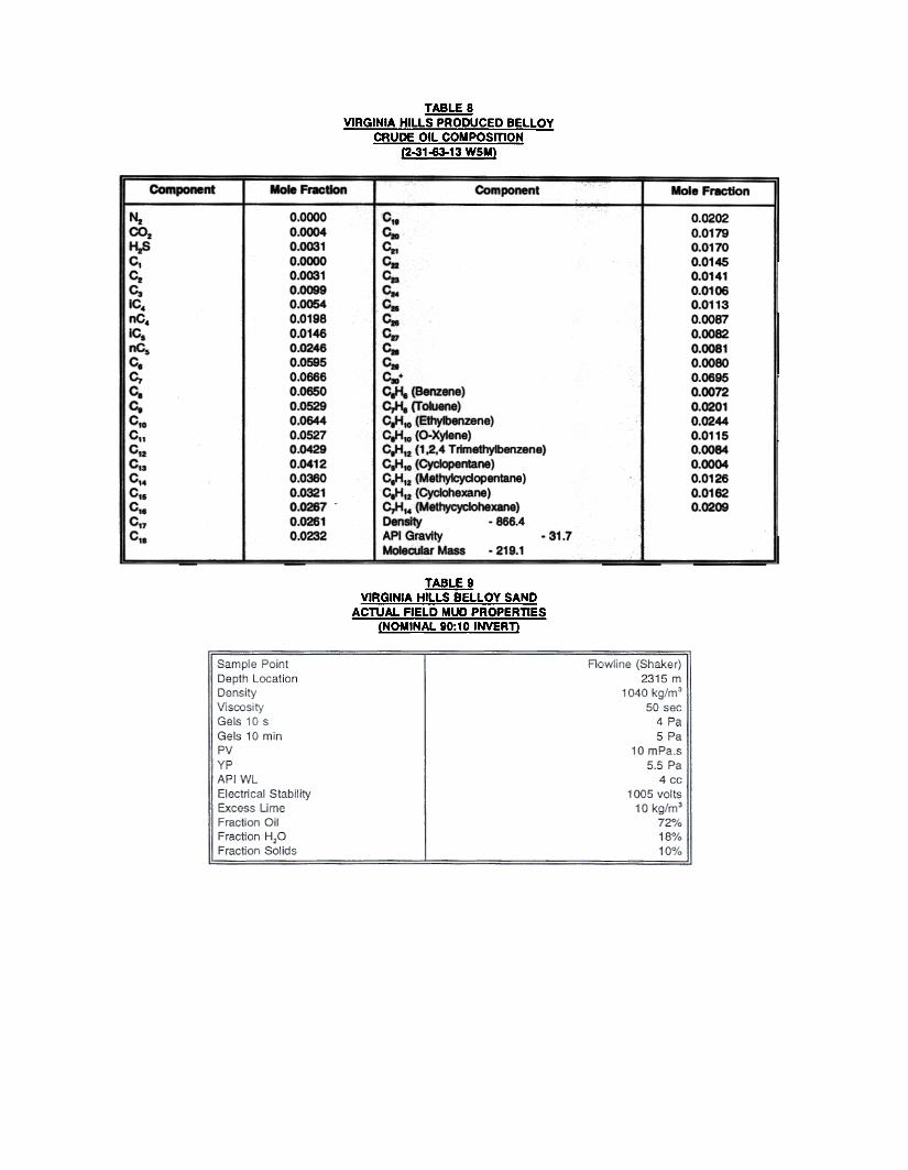
TABLE 8VIRGINIA HILLS PRODUCED BELLOY
CRUDE OIL COMPOSmON(2-31-63-13 WSM)
Component Mole Fr8CtIon Component Mole Fraction
HeCOzHzSC,CzCzIC.nC.JC.nC.c.c,c.
,c.C.Cw,CuCiaCMCt.C"C"C.
0.0000O.~0.00310.00000.OCXJ10.00990.00540.01980.014f0.024E0.05950.06660.06500.05290.06440.05270.042'0.04120.03600.~10.02670.02610.0232
0.02020.01790.01700.01450.01410.01060.0113o. 00870.00820.00810 . 00800.06950.00720.02010.02440.01150.00840 . 00040.01260.01620.0200
c,.c.CII
c.c.c..c.c..~c..Cac.-C-fi. (Benz~)~ (T oIu«\e)C.HIO (Ethyibenzene)CaHlO (o-Xytene)CaHlI (1.2,4 Trlm8thyt)81zene)C,H,o (~M)C,H'2 (M8thy1cydopentane)c.H'2 (Cyckj1exane)~'4 (Methycyck)h8xane)Density . 866.4API Gravity .MoIeI:IMr Mass . 219.1
31.7
TABLE 9VIRGINIA HILLS BELLOY SAND
ACTUAL FIELD MUD PROPERTIES(NOMINAL 90:10 INVERT)

(/):J~~a..«IJ..
(/)IJ..-J~::!«:I:w«-J
~-c
wZ
-~
(53:J~
IJ..~
>z
IJ.. I
0-J--Jt=W
c:I:z(/)0
U~-0~W(/)W~

(/):)~~Q
.«u.u.
~«w..JC(/)-..J:)..J..J-u.
:J:z
N~
QW
~t:
,,~C
:)"Z
~-O
->U
u. I
..J~..J-w
O:J:>C
/)~WC/)
W~CWUz:5«aJ~WCZ=>

wUZ<~~0u.~W
(/)0..-JC-J--::>:I:-J<
u.M
-WW
~-J
~~
<::>
~U
~-(/)
- >
I
u. I
C-J-J-JWw
U:
:I:u.(/)0
Z0(/)~~~0U
"C~~-'0
~~
~t
~ co
- a..
~
~O
J ('II
I ~
« 0
0) ..-
! -
8"C~~-f/) -
~g:
f~
m
- co
~
a..
m
~,
0"'-!8
c"0
:~f
"'" J
0 -<
.>
0(/)
"6~+
m ~
0) C
e ~
0 -
<.>
2)0)


FIGURE 5SHELL - VIRGINIA HILLS
15-30-63-13 W5MFINAL COMPLETION SCHEMATIC
Related Documents