Enhancement of laminar and transitional flow heat transfer in tubes by means of wire coil inserts Alberto Garcı ´a a, * , Juan P. Solano a , Pedro G. Vicente b , Antonio Viedma a a Universidad Polite ´cnica de Cartagena, Departamento de Ingenierı ´a Te ´rmica y de Fluidos, Campus de la Muralla del Mar, 30202 Cartagena, Spain b Universidad Miguel Herna ´ ndez, Departamento de Ingenierı ´a de Sistemas Industriales, Avenida de la Universidad s/n, 03202 Elche, Spain Received 27 March 2006 Available online 23 March 2007 Abstract This work presents an extensive experimental study on three wire coils of different pitch inserted in a smooth tube in laminar and transition regimes. Isothermal pressure drop tests and heat transfer experiments under uniform heat flux conditions have been carried out. The friction factor increases lie between 5% and 40% in the fully laminar region. The transition from laminar flow to turbulent flow is continuous, without the instabilities and the pressure drop fluctuations that a smooth tube presents. Heat transfer experiments have been performed in the flow ranges: Re ¼ 10–2500; Pr ¼ 200–700 and Ra ¼ 3 10 6 –10 8 . At Reynolds numbers below 200, wire coils do not enhance heat transfer with respect to a smooth tube. For Reynolds numbers between 200 and 1000, wire coils remarkably increase heat transfer. At Reynolds numbers above Re 1000–1300, transition from laminar to turbulent flow takes place. At Reynolds number around 1000, wire inserts increase the heat transfer coefficient up to eight times with respect to the smooth tube. A performance comparison between wire coils and twisted tape inserts has shown that wire inserts perform better than twisted tapes in the low Reynolds number range: Re ¼ 700–2500. Ó 2007 Elsevier Ltd. All rights reserved. Keywords: Heat transfer enhancement; Wire coil inserts; Heat exchangers; Turbulence promoters 1. Introduction Heat transfer processes of viscous fluids usually take place in laminar or transitional regimes, where transfer rates are particularly low. Heat exchangers that work under these flow conditions are usually candidates to undergo an enhancement technique. Among the different techniques which are effective to improve the thermohy- draulic behaviour in the tube-side in single-phase laminar flow, the insert devices stand out. The dominant literature (Bergles [1], Webb and Kim [2]) usually mentions five types: wire coils, twisted tapes, extended surface devices, mesh inserts and displaced elements. The main advantage of these types in respect to other enhancement techniques such as the artificial roughness by mechanical deformation or internal fin types is that they allow an easy installation in an existing smooth-tube heat exchanger. Due mainly to its low cost, the insert devices which are most frequently used in engineering applications are wire coils and twisted tapes. It can be stated that both wires coils and twisted tapes, become candidates to update an existing tube exchanger. The two recent state-of-the-art revisions on insert devices carried out by Wang and Sunde ´n [3] and Dewan et al. [4] focus mainly on these two devices. The thermohydraulic behaviour of twisted tapes in laminar regime has been widely studied. Design correlations to pre- dict both the isothermal friction factor (Manglik et al. [5]) and the Nusselt number under uniform heat flux (Bandyo- padhyay et al. [6], Hong and Bergles [7]) and constant wall 0017-9310/$ - see front matter Ó 2007 Elsevier Ltd. All rights reserved. doi:10.1016/j.ijheatmasstransfer.2007.01.015 * Corresponding author. E-mail address: [email protected] (A. Garcı ´a). www.elsevier.com/locate/ijhmt International Journal of Heat and Mass Transfer 50 (2007) 3176–3189

Welcome message from author
This document is posted to help you gain knowledge. Please leave a comment to let me know what you think about it! Share it to your friends and learn new things together.
Transcript

www.elsevier.com/locate/ijhmt
International Journal of Heat and Mass Transfer 50 (2007) 3176–3189
Enhancement of laminar and transitional flow heat transferin tubes by means of wire coil inserts
Alberto Garcıa a,*, Juan P. Solano a, Pedro G. Vicente b, Antonio Viedma a
a Universidad Politecnica de Cartagena, Departamento de Ingenierıa Termica y de Fluidos, Campus de la Muralla del Mar, 30202 Cartagena, Spainb Universidad Miguel Hernandez, Departamento de Ingenierıa de Sistemas Industriales, Avenida de la Universidad s/n, 03202 Elche, Spain
Received 27 March 2006Available online 23 March 2007
Abstract
This work presents an extensive experimental study on three wire coils of different pitch inserted in a smooth tube in laminar andtransition regimes. Isothermal pressure drop tests and heat transfer experiments under uniform heat flux conditions have been carriedout.
The friction factor increases lie between 5% and 40% in the fully laminar region. The transition from laminar flow to turbulent flow iscontinuous, without the instabilities and the pressure drop fluctuations that a smooth tube presents.
Heat transfer experiments have been performed in the flow ranges: Re ¼ 10–2500; Pr ¼ 200–700 and Ra ¼ 3� 106–108. At Reynoldsnumbers below 200, wire coils do not enhance heat transfer with respect to a smooth tube. For Reynolds numbers between 200 and 1000,wire coils remarkably increase heat transfer. At Reynolds numbers above Re � 1000–1300, transition from laminar to turbulent flowtakes place. At Reynolds number around 1000, wire inserts increase the heat transfer coefficient up to eight times with respect to thesmooth tube.
A performance comparison between wire coils and twisted tape inserts has shown that wire inserts perform better than twisted tapes inthe low Reynolds number range: Re ¼ 700–2500.� 2007 Elsevier Ltd. All rights reserved.
Keywords: Heat transfer enhancement; Wire coil inserts; Heat exchangers; Turbulence promoters
1. Introduction
Heat transfer processes of viscous fluids usually takeplace in laminar or transitional regimes, where transferrates are particularly low. Heat exchangers that workunder these flow conditions are usually candidates toundergo an enhancement technique. Among the differenttechniques which are effective to improve the thermohy-draulic behaviour in the tube-side in single-phase laminarflow, the insert devices stand out. The dominant literature(Bergles [1], Webb and Kim [2]) usually mentions fivetypes: wire coils, twisted tapes, extended surface devices,mesh inserts and displaced elements. The main advantage
0017-9310/$ - see front matter � 2007 Elsevier Ltd. All rights reserved.
doi:10.1016/j.ijheatmasstransfer.2007.01.015
* Corresponding author.E-mail address: [email protected] (A. Garcıa).
of these types in respect to other enhancement techniquessuch as the artificial roughness by mechanical deformationor internal fin types is that they allow an easy installation inan existing smooth-tube heat exchanger.
Due mainly to its low cost, the insert devices which aremost frequently used in engineering applications are wirecoils and twisted tapes. It can be stated that both wirescoils and twisted tapes, become candidates to update anexisting tube exchanger. The two recent state-of-the-artrevisions on insert devices carried out by Wang and Sunden[3] and Dewan et al. [4] focus mainly on these two devices.The thermohydraulic behaviour of twisted tapes in laminarregime has been widely studied. Design correlations to pre-dict both the isothermal friction factor (Manglik et al. [5])and the Nusselt number under uniform heat flux (Bandyo-padhyay et al. [6], Hong and Bergles [7]) and constant wall
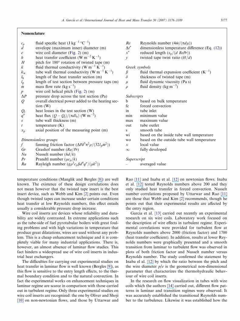
Nomenclature
cp fluid specific heat (J kg�1 �C�1)d envelope (maximum inner) diameter (m)e wire coil diameter (Fig. 2) (m)h heat transfer coefficient (W m�2 K�1)H pitch for 180� rotation of twisted tape (m)k fluid thermal conductivity (W m�1 K�1)kw tube wall thermal conductivity (W m�1 K�1)lh length of the heat transfer section (m)lp length of test section between pressure taps (m)_m mass flow rate (kg s�1)p wire coil helical pitch (Fig. 2) (m)DP pressure drop across the test section (Pa)Q overall electrical power added to the heating sec-
tion (W)Ql heat losses in the test section (W)q00 heat flux ðQ� QlÞ=ðpdlhÞ (W m�2)s tube wall thickness (m)t temperature (K)xp axial position of the measuring point (m)
Dimensionless groups
f fanning friction factor (DPd5p2q=ð32lp _m2Þ)Gr Grashof number (Ra=Pr)Nu Nusselt number (hd=k)Pr Prandtl number (lcp=k)Ra Rayleigh number (gq2cpbd4q00=ðlk2Þ)
Re Reynolds number (4 _m=ðpdlÞ)Dt* dimensionless temperature difference (Eq. (12))x* reduced length (xp=ðd RePrÞ)y twisted tape twist ratio (H=d)
Greek symbols
b fluid thermal expansion coefficient (K�1)d thickness of twisted tape (m)l fluid dynamic viscosity (Pa s)q fluid density (kg m�3)
Subscripts
b based on bulk temperaturefc forced convectionin tube inletmin minimum valuemax maximum valueout tube outlets smooth tubewi based on the inside tube wall temperaturewo based on the outside tube wall temperaturex local value1 fully developed
Superscript
– averaged value
A. Garcıa et al. / International Journal of Heat and Mass Transfer 50 (2007) 3176–3189 3177
temperature conditions (Manglik and Bergles [8]) are wellknown. The existence of these design correlations doesnot mean however that the twisted tape insert is the bestinsert device, such as Webb and Kim [2] points out. Eventhough twisted tapes can increase under certain conditionsheat transfer at low Reynolds numbers, this effect entailsusually a considerable pressure drop increase.
Wire coil inserts are devices whose reliability and dura-bility are widely contrasted. In extreme applications suchas the tube-side of fuel pyrotubular boilers with great foul-ing problems and with high variations in temperature thatproduce great dilatations, wires are used without any prob-lem. This is a cheap enhancement technique and it is com-pletely viable for many industrial applications. There is,however, an almost absence of laminar flow studies. Thisfact hinders a widespread use of wire coil inserts in indus-trial heat exchangers.
The difficulties for carrying out experimental studies onheat transfer in laminar flow is well known (Bergles [9]), asthis flow is sensitive to the entry length effects, to the ther-mal boundary condition and to the natural convection. Infact the experimental works on enhancement techniques inlaminar regime are scarce in comparison with those carriedout in turbulent regime. Only three experimental studies onwire coil inserts are recognized: the one by Oliver and Shoji[10] on non-newtonian flows, and those by Uttarwar and
Rao [11] and Inaba et al. [12] on newtonian flows. Inabaet al. [12] tested Reynolds numbers above 200 and theyonly studied heat transfer in forced convection. Nusseltnumber correlations proposed by Uttarwar and Rao [11]are those that Webb and Kim [2] recommends, though hepoints out that their experimental results are affected bythe entry region.
Garcia et al. [13] carried out recently an experimentalresearch on six wire coils. Laboratory work focused onthe description of wire effects in turbulent regime. Experi-mental correlations were provided for turbulent flow atReynolds numbers above 2000 (friction factor) and 1700(heat transfer coefficient). In addition, results at lower Rey-nolds numbers were graphically presented and a smoothtransition from laminar to turbulent flow was observed inplots of both friction factor and Nusselt number versusReynolds number. The study confirmed the statement byInaba el al. [12] by which the ratio between the pitch andthe wire diameter p/e is the geometrical non-dimensionalparameter that characterizes the thermohydraulic behav-iour of wire coil inserts.
In the research on flow visualization in tubes with wirecoils which the authors [14] carried out, different flow pat-terns in laminar and transition regimes were observed. Itwas accurately established the transitional Reynolds num-ber to the turbulence. Likewise it was established how the
3178 A. Garcıa et al. / International Journal of Heat and Mass Transfer 50 (2007) 3176–3189
flow patterns affect the pressure drop. Results from thevisualization research have been also applied to the presentexperimental work. A new set of experiments has been per-formed on three wires of p/e between 16.4 and 44.3, relat-ing the flow physical mechanism to the heat transferenhancement in laminar and transition flows. Correlationsfor the wires heat transfer both for forced and mixed con-vection are also proposed, and the criterion to choose oneof those is established. Finally the performance of wire coilinserts is compared to that of the twisted tapes inserts andthe most appropriate conditions to use one or anotherenhancement technique are suggested.
2. Experimental set-up
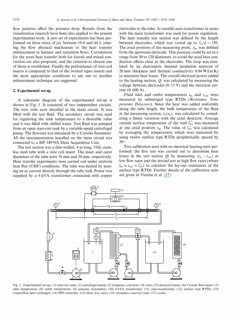
A schematic diagram of the experimental set-up isshown in Fig. 1. It consisted of two independent circuits.The wire coils were installed in the main circuit. It wasfilled with the test fluid. The secondary circuit was usedfor regulating the tank temperature to a desirable valueand it was filled with chilled water. Test fluid was pumpedfrom an open reservoir tank by a variable-speed centrifugalpump. The flowrate was measured by a Coriolis flowmeter.All the instrumentation installed on the main circuit wasconnected to a HP 34970A Data Acquisition Unit.
The test section was a thin-walled, 4 m long, 316L stain-less steel tube with a wire coil insert. The inner and outerdiameters of the tube were 18 mm and 20 mm, respectively.Heat transfer experiments were carried out under uniformheat flux (UHF) conditions. The tube was heated by pass-ing an ac current directly through the tube wall. Power wassupplied by a 6 kVA transformer connected with copper
Fig. 1. Experimental set-up. (1) reservoir tank; (2) centrifugal pump; (3) frequinlet temperature; (8) outlet temperature; (9) pressure transmitter; (10) 6 kcounterflow heat exchanger; (14) PID controller; (15) three way valve; (16) se
electrodes to the tube. A variable auto-transformer in serieswith the main transformer was used for power regulation.The heat transfer test section was defined by the lengthbetween electrodes, which was varied up to lh=d ¼ 150.The axial position of the measuring point, xp, was definedfrom the upstream electrode. This position could be set in arange from 30 to 120 diameters, to avoid the axial heat con-duction effects close to the electrodes. The loop was insu-lated by an elastomeric thermal insulation material of20 mm thickness and thermal conductivity 0.04 W/(m K)to minimize heat losses. The overall electrical power addedto the heating section, Q, was calculated by measuring thevoltage between electrodes (0–15 V) and the electrical cur-rent (0–600 A).
Fluid inlet and outlet temperatures tin and tout weremeasured by submerged type RTDs (Resistance Tem-
perature Detectors). Since the heat was added uniformlyalong the tube length, the bulk temperature of the fluidat the measuring section, tbðxpÞ, was calculated by consid-ering a linear variation with the axial direction. Averageoutside surface temperature of the wall two was measuredat one axial position xp. The value of two was calculatedby averaging the temperatures which were measured byusing twelve surface type RTDs peripherically spaced by30�.
Two calibration tests with no electrical heating were per-formed: the first test was carried out to determine heatlosses in the test section Ql by measuring ðtin � toutÞ atlow flow rates and the second test at high flow rates (wheretin � tout � two) to calculate the lay-out resistances of thesurface type RTDs. Further details of the calibration testsare given in Vicente et al. [17].
ency converter; (4) valve; (5) electrical heater; (6) Coriolis flow-meter; (7)VA transformer; (11) auto-transformer; (12) surface type RTDs; (13)
condary reservoir tank; (17) cooler.
p
e
d
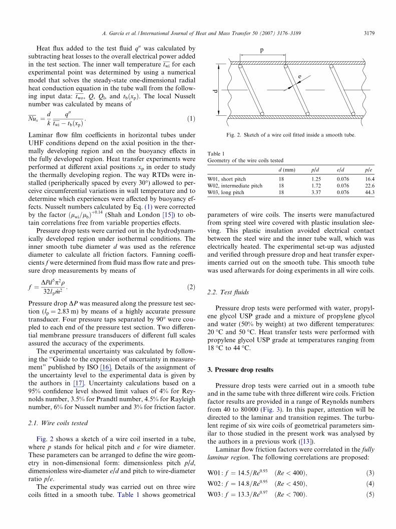
Fig. 2. Sketch of a wire coil fitted inside a smooth tube.
Table 1Geometry of the wire coils tested
d (mm) p/d e/d p/e
W01, short pitch 18 1.25 0.076 16.4W02, intermediate pitch 18 1.72 0.076 22.6W03, long pitch 18 3.37 0.076 44.3
A. Garcıa et al. / International Journal of Heat and Mass Transfer 50 (2007) 3176–3189 3179
Heat flux added to the test fluid q00 was calculated bysubtracting heat losses to the overall electrical power addedin the test section. The inner wall temperature twi for eachexperimental point was determined by using a numericalmodel that solves the steady-state one-dimensional radialheat conduction equation in the tube wall from the follow-ing input data: two, Q, Ql, and tbðxpÞ. The local Nusseltnumber was calculated by means of
Nux ¼dk
q00
twi � tbðxpÞ: ð1Þ
Laminar flow film coefficients in horizontal tubes underUHF conditions depend on the axial position in the ther-mally developing region and on the buoyancy effects inthe fully developed region. Heat transfer experiments wereperformed at different axial positions xp in order to studythe thermally developing region. The way RTDs were in-stalled (peripherically spaced by every 30�) allowed to per-ceive circumferential variations in wall temperature and todetermine which experiences were affected by buoyancy ef-fects. Nusselt numbers calculated by Eq. (1) were correctedby the factor ðlwi=lbÞ
þ0:14 (Shah and London [15]) to ob-tain correlations free from variable properties effects.
Pressure drop tests were carried out in the hydrodynam-ically developed region under isothermal conditions. Theinner smooth tube diameter d was used as the referencediameter to calculate all friction factors. Fanning coeffi-cients f were determined from fluid mass flow rate and pres-sure drop measurements by means of
f ¼ DPd5p2q32lp _m2
: ð2Þ
Pressure drop DP was measured along the pressure test sec-tion (lp = 2.83 m) by means of a highly accurate pressuretransducer. Four pressure taps separated by 90� were cou-pled to each end of the pressure test section. Two differen-tial membrane pressure transducers of different full scalesassured the accuracy of the experiments.
The experimental uncertainty was calculated by follow-ing the ‘‘Guide to the expression of uncertainty in measure-ment” published by ISO [16]. Details of the assignment ofthe uncertainty level to the experimental data is given bythe authors in [17]. Uncertainty calculations based on a95% confidence level showed limit values of 4% for Rey-nolds number, 3.5% for Prandtl number, 4.5% for Rayleighnumber, 6% for Nusselt number and 3% for friction factor.
2.1. Wire coils tested
Fig. 2 shows a sketch of a wire coil inserted in a tube,where p stands for helical pitch and e for wire diameter.These parameters can be arranged to define the wire geom-etry in non-dimensional form: dimensionless pitch p/d,dimensionless wire-diameter e/d and pitch to wire-diameterratio p/e.
The experimental study was carried out on three wirecoils fitted in a smooth tube. Table 1 shows geometrical
parameters of wire coils. The inserts were manufacturedfrom spring steel wire covered with plastic insulation slee-ving. This plastic insulation avoided electrical contactbetween the steel wire and the inner tube wall, which waselectrically heated. The experimental set-up was adjustedand verified through pressure drop and heat transfer exper-iments carried out on the smooth tube. This smooth tubewas used afterwards for doing experiments in all wire coils.
2.2. Test fluids
Pressure drop tests were performed with water, propyl-ene glycol USP grade and a mixture of propylene glycoland water (50% by weight) at two different temperatures:20 �C and 50 �C. Heat transfer tests were performed withpropylene glycol USP grade at temperatures ranging from18 �C to 44 �C.
3. Pressure drop results
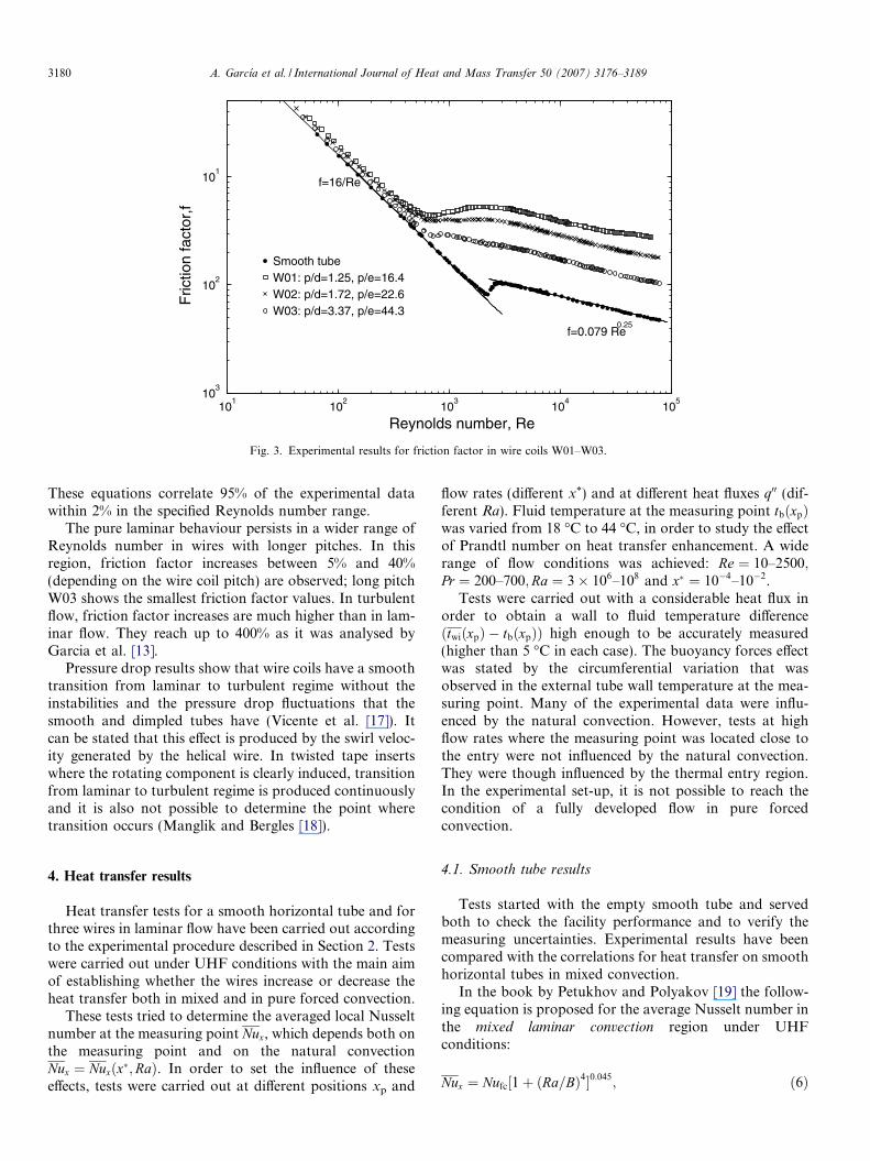
Pressure drop tests were carried out in a smooth tubeand in the same tube with three different wire coils. Frictionfactor results are provided in a range of Reynolds numbersfrom 40 to 80000 (Fig. 3). In this paper, attention will bedirected to the laminar and transition regimes. The turbu-lent regime of six wire coils of geometrical parameters sim-ilar to those studied in the present work was analysed bythe authors in a previous work ([13]).
Laminar flow friction factors were correlated in the fullylaminar region. The following correlations are proposed:
W01 : f ¼ 14:5=Re0:93 ðRe < 400Þ; ð3ÞW02 : f ¼ 14:8=Re0:95 ðRe < 450Þ; ð4ÞW03 : f ¼ 13:3=Re0:97 ðRe < 700Þ: ð5Þ
101
102
103
104
105
10
Reynolds number, Re
Fric
tion
fact
or,f
3
102
101
Smooth tubeW01: p/d=1.25, p/e=16.4W02: p/d=1.72, p/e=22.6W03: p/d=3.37, p/e=44.3
f=16/Re
f=0.079 Re0.25
Fig. 3. Experimental results for friction factor in wire coils W01–W03.
3180 A. Garcıa et al. / International Journal of Heat and Mass Transfer 50 (2007) 3176–3189
These equations correlate 95% of the experimental datawithin 2% in the specified Reynolds number range.
The pure laminar behaviour persists in a wider range ofReynolds number in wires with longer pitches. In thisregion, friction factor increases between 5% and 40%(depending on the wire coil pitch) are observed; long pitchW03 shows the smallest friction factor values. In turbulentflow, friction factor increases are much higher than in lam-inar flow. They reach up to 400% as it was analysed byGarcia et al. [13].
Pressure drop results show that wire coils have a smoothtransition from laminar to turbulent regime without theinstabilities and the pressure drop fluctuations that thesmooth and dimpled tubes have (Vicente et al. [17]). Itcan be stated that this effect is produced by the swirl veloc-ity generated by the helical wire. In twisted tape insertswhere the rotating component is clearly induced, transitionfrom laminar to turbulent regime is produced continuouslyand it is also not possible to determine the point wheretransition occurs (Manglik and Bergles [18]).
4. Heat transfer results
Heat transfer tests for a smooth horizontal tube and forthree wires in laminar flow have been carried out accordingto the experimental procedure described in Section 2. Testswere carried out under UHF conditions with the main aimof establishing whether the wires increase or decrease theheat transfer both in mixed and in pure forced convection.
These tests tried to determine the averaged local Nusseltnumber at the measuring point Nux, which depends both onthe measuring point and on the natural convectionNux ¼ Nuxðx�;RaÞ. In order to set the influence of theseeffects, tests were carried out at different positions xp and
flow rates (different x*) and at different heat fluxes q00 (dif-ferent Ra). Fluid temperature at the measuring point tbðxpÞwas varied from 18 �C to 44 �C, in order to study the effectof Prandtl number on heat transfer enhancement. A widerange of flow conditions was achieved: Re ¼ 10–2500;Pr ¼ 200–700;Ra ¼ 3� 106–108 and x� ¼ 10�4–10�2.
Tests were carried out with a considerable heat flux inorder to obtain a wall to fluid temperature differenceðtwiðxpÞ � tbðxpÞÞ high enough to be accurately measured(higher than 5 �C in each case). The buoyancy forces effectwas stated by the circumferential variation that wasobserved in the external tube wall temperature at the mea-suring point. Many of the experimental data were influ-enced by the natural convection. However, tests at highflow rates where the measuring point was located close tothe entry were not influenced by the natural convection.They were though influenced by the thermal entry region.In the experimental set-up, it is not possible to reach thecondition of a fully developed flow in pure forcedconvection.
4.1. Smooth tube results
Tests started with the empty smooth tube and servedboth to check the facility performance and to verify themeasuring uncertainties. Experimental results have beencompared with the correlations for heat transfer on smoothhorizontal tubes in mixed convection.
In the book by Petukhov and Polyakov [19] the follow-ing equation is proposed for the average Nusselt number inthe mixed laminar convection region under UHFconditions:
Nux ¼ Nufc½1þ ðRa=BÞ4�0:045; ð6Þ
A. Garcıa et al. / International Journal of Heat and Mass Transfer 50 (2007) 3176–3189 3181
where Nufc is the local Nusselt number in pure forced con-
vection, given by
Nufc ¼ 4:36þ 1:31ðx�Þ�1=3 exp �13ffiffiffiffix�p� �
; ð7Þ
and B is a function of the dimensionless length x*
B ¼ 5:0� 103ðx�Þ�1 if x� < 1:7� 10�3;
B ¼ 1:8� 104 þ 55ðx�Þ�1:7 if x� > 1:7� 10�3:
In pure forced convection, the fully developed thermal re-gion starts by x� � 0:1; here the Nusselt number becomesconstant to the already known value of Nufc ¼ 4:36. How-ever, in mixed convection the thermally developing regionis much smaller ðx� � 0:002 at Ra ¼ 4� 106Þ. In the fullydeveloped region, the Nusselt number shows an asymptoticbehaviour ðx� ! 1;B ¼ 1:8� 104Þ and Eq. (6) is:
Nu1 ¼ 4:36½1þ ðRa=18000Þ4�0:045: ð8Þ
Nu1 is the Nusselt number in the fully developed region.From Eq. (7) it can be inferred that in the entry regionthe Nusselt number for pure forced convection, Nufc, isproportional to ðx�Þ�1=3. On the other hand, Eq. (8) showsthat in the fully developed region, Nu1 is proportional toRa0:18.
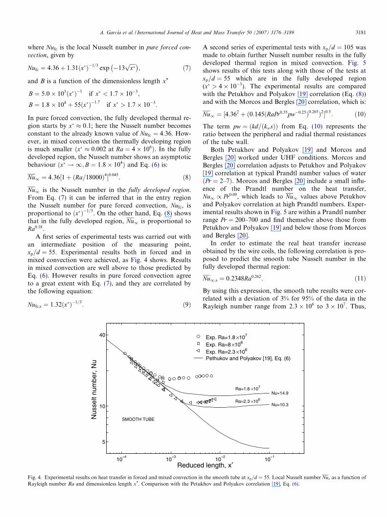
A first series of experimental tests was carried out withan intermediate position of the measuring point,xp=d ¼ 55. Experimental results both in forced and inmixed convection were achieved, as Fig. 4 shows. Resultsin mixed convection are well above to those predicted byEq. (6). However results in pure forced convection agreeto a great extent with Eq. (7), and they are correlated bythe following equation:
Nufc;s ¼ 1:32ðx�Þ�1=3: ð9Þ
10 10
5
10
40
Reduced
Nus
selt
num
ber,
Nu
SMOOTH TUBE
Fig. 4. Experimental results on heat transfer in forced and mixed convection inRayleigh number Ra and dimensionless length x*. Comparison with the Petuk
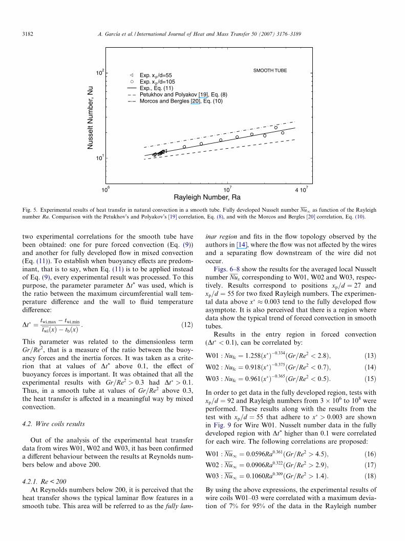
A second series of experimental tests with xp=d ¼ 105 wasmade to obtain further Nusselt number results in the fullydeveloped thermal region in mixed convection. Fig. 5shows results of this tests along with those of the tests atxp=d ¼ 55 which are in the fully developed region(x� > 4� 10�3). The experimental results are comparedwith the Petukhov and Polyakov [19] correlation (Eq. (8))and with the Morcos and Bergles [20] correlation, which is:
Nu1 ¼ ½4:362 þ ð0:145ðRaPr0:35pw�0:25Þ0:265Þ2�0:5: ð10Þ
The term pw ¼ ðkd=ðkwsÞÞ from Eq. (10) represents theratio between the peripheral and radial thermal resistancesof the tube wall.
Both Petukhov and Polyakov [19] and Morcos andBergles [20] worked under UHF conditions. Morcos andBergles [20] correlation adjusts to Petukhov and Polyakov[19] correlation at typical Prandtl number values of waterðPr ¼ 2–7Þ. Morcos and Bergles [20] include a small influ-ence of the Prandtl number on the heat transfer,Nu1 / Pr0:09, which leads to Nu1 values above Petukhovand Polyakov correlation at high Prandtl numbers. Exper-imental results shown in Fig. 5 are within a Prandtl numberrange Pr ¼ 200–700 and find themselve above those fromPetukhov and Polyakov [19] and below those from Morcosand Bergles [20].
In order to estimate the real heat transfer increaseobtained by the wire coils, the following correlation is pro-posed to predict the smooth tube Nusselt number in thefully developed thermal region:
Nu1;s ¼ 0:2348Ra0:262: ð11Þ
By using this expression, the smooth tube results were cor-related with a deviation of 3% for 95% of the data in theRayleigh number range from 2:3� 106 to 3� 107. Thus,
10 10 length, x*
Nu=10.3
Nu=14.9
Ra=2.3 ×10⁶
Ra=1.8 ×10⁷
Exp. Ra=1.8 ×10⁷
Exp. Ra=8 ×10⁶
Exp. Ra=2.3 ×10⁶
Pethukov and Polyakov [19], Eq. (6)
the smooth tube at xp=d ¼ 55. Local Nusselt number Nux as a function ofhov and Polyakov correlation [19], Eq. (6).
106
10 4 107 7
Rayleigh Number, Ra
Nus
selt
Num
ber,
Nu
101
102
p
p
SMOOTH TUBEExp. x /d=55Exp. x /d=105Exp., Eq. (11)Petukhov and Polyakov [19], Eq. (8)Morcos and Bergles [20], Eq. (10).
Fig. 5. Experimental results of heat transfer in natural convection in a smooth tube. Fully developed Nusselt number Nu1 as function of the Rayleighnumber Ra. Comparison with the Petukhov’s and Polyakov’s [19] correlation, Eq. (8), and with the Morcos and Bergles [20] correlation, Eq. (10).
3182 A. Garcıa et al. / International Journal of Heat and Mass Transfer 50 (2007) 3176–3189
two experimental correlations for the smooth tube havebeen obtained: one for pure forced convection (Eq. (9))and another for fully developed flow in mixed convection(Eq. (11)). To establish when buoyancy effects are predom-inant, that is to say, when Eq. (11) is to be applied insteadof Eq. (9), every experimental result was processed. To thispurpose, the parameter parameter Dt* was used, which isthe ratio between the maximum circumferential wall tem-perature difference and the wall to fluid temperaturedifference:
Dt� ¼ twi;max � twi;min
twiðxÞ � tbðxÞ: ð12Þ
This parameter was related to the dimensionless termGr=Re2, that is a measure of the ratio between the buoy-ancy forces and the inertia forces. It was taken as a crite-rion that at values of Dt* above 0.1, the effect ofbuoyancy forces is important. It was obtained that all theexperimental results with Gr=Re2 > 0:3 had Dt� > 0:1.Thus, in a smooth tube at values of Gr=Re2 above 0.3,the heat transfer is affected in a meaningful way by mixedconvection.
4.2. Wire coils results
Out of the analysis of the experimental heat transferdata from wires W01, W02 and W03, it has been confirmeda different behaviour between the results at Reynolds num-bers below and above 200.
4.2.1. Re < 200
At Reynolds numbers below 200, it is perceived that theheat transfer shows the typical laminar flow features in asmooth tube. This area will be referred to as the fully lam-
inar region and fits in the flow topology observed by theauthors in [14], where the flow was not affected by the wiresand a separating flow downstream of the wire did notoccur.
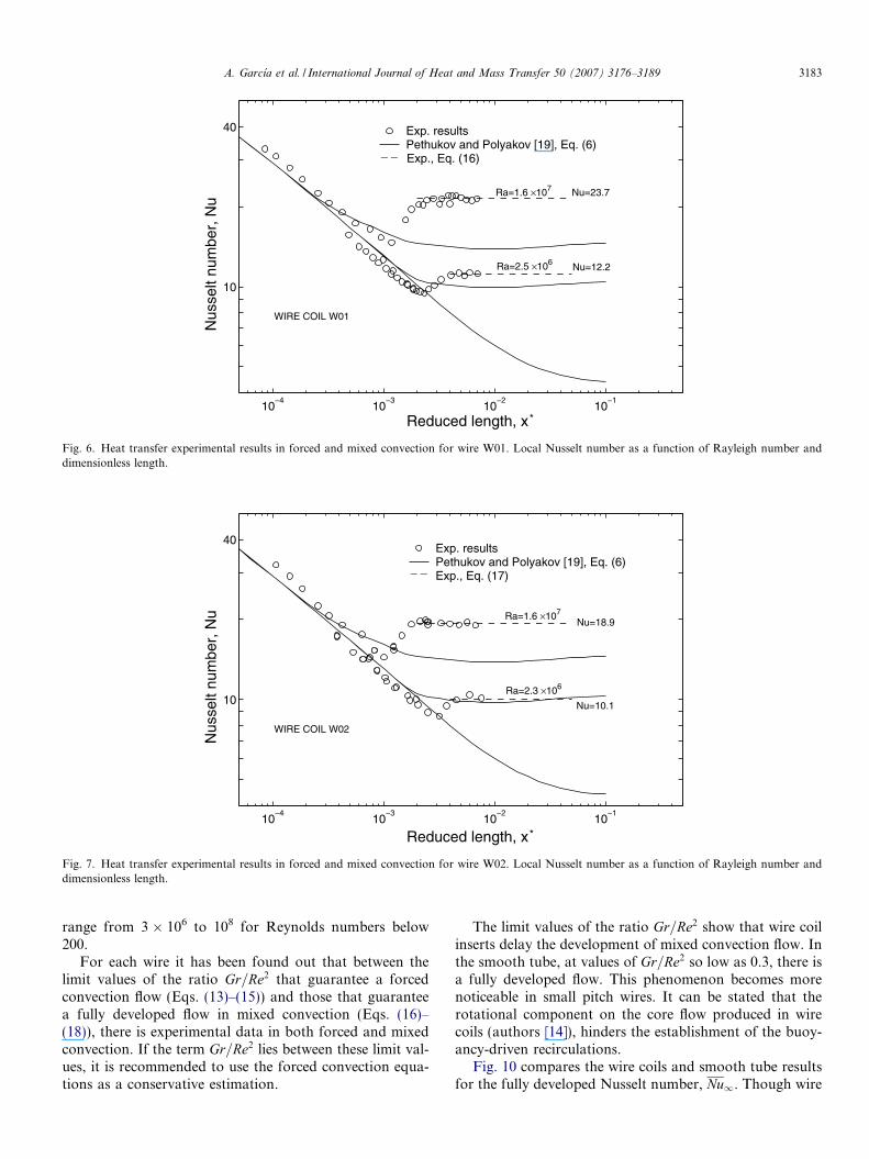
Figs. 6–8 show the results for the averaged local Nusseltnumber Nux corresponding to W01, W02 and W03, respec-tively. Results correspond to positions xp=d ¼ 27 andxp=d ¼ 55 for two fixed Rayleigh numbers. The experimen-tal data above x� � 0:003 tend to the fully developed flowasymptote. It is also perceived that there is a region wheredata show the typical trend of forced convection in smoothtubes.
Results in the entry region in forced convection(Dt� < 0:1), can be correlated by:
W01 : Nufc ¼ 1:258ðx�Þ�0:334ðGr=Re2 < 2:8Þ; ð13ÞW02 : Nufc ¼ 0:918ðx�Þ�0:375ðGr=Re2 < 0:7Þ; ð14ÞW03 : Nufc ¼ 0:961ðx�Þ�0:365ðGr=Re2 < 0:5Þ: ð15Þ
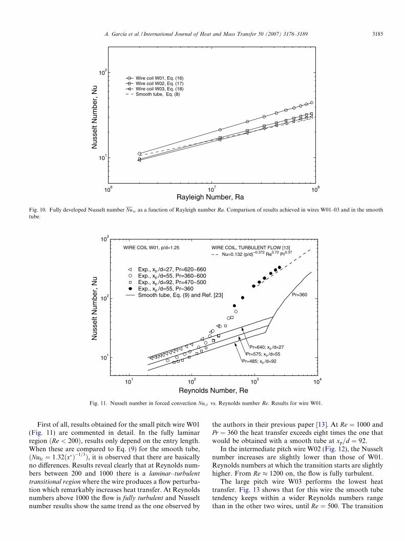
In order to get data in the fully developed region, tests withxp=d ¼ 92 and Rayleigh numbers from 3 � 106 to 108 wereperformed. These results along with the results from thetest with xp=d ¼ 55 that adhere to x� > 0:003 are shownin Fig. 9 for Wire W01. Nusselt number data in the fullydeveloped region with Dt* higher than 0.1 were correlatedfor each wire. The following correlations are proposed:
W01 : Nu1 ¼ 0:0596Ra0:361ðGr=Re2 > 4:5Þ; ð16ÞW02 : Nu1 ¼ 0:0906Ra0:322ðGr=Re2 > 2:9Þ; ð17ÞW03 : Nu1 ¼ 0:1060Ra0:309ðGr=Re2 > 1:4Þ: ð18Þ
By using the above expressions, the experimental results ofwire coils W01–03 were correlated with a maximum devia-tion of 7% for 95% of the data in the Rayleigh number
10 10 10 10
10
40
Reduced length, x*
Nus
selt
num
ber,
Nu
Nu=12.2
Nu=23.7
Ra=2.5 ×10⁶
Ra=1.6 ×10⁷
Exp. resultsPethukov and Polyakov [19], Eq. (6)
_ _ Exp., Eq. (16)
WIRE COIL W01
Fig. 6. Heat transfer experimental results in forced and mixed convection for wire W01. Local Nusselt number as a function of Rayleigh number anddimensionless length.
10 10 10 10
10
40
Reduced length, x*
Nus
selt
num
ber,
Nu
Nu=10.1
Nu=18.9
Ra=2.3 ×10⁶
Ra=1.6 ×10⁷
Exp. resultsPethukov and Polyakov [19], Eq. (6)Exp., Eq. (17)_ _
WIRE COIL W02
Fig. 7. Heat transfer experimental results in forced and mixed convection for wire W02. Local Nusselt number as a function of Rayleigh number anddimensionless length.
A. Garcıa et al. / International Journal of Heat and Mass Transfer 50 (2007) 3176–3189 3183
range from 3 � 106 to 108 for Reynolds numbers below200.
For each wire it has been found out that between thelimit values of the ratio Gr=Re2 that guarantee a forcedconvection flow (Eqs. (13)–(15)) and those that guaranteea fully developed flow in mixed convection (Eqs. (16)–(18)), there is experimental data in both forced and mixedconvection. If the term Gr=Re2 lies between these limit val-ues, it is recommended to use the forced convection equa-tions as a conservative estimation.
The limit values of the ratio Gr=Re2 show that wire coilinserts delay the development of mixed convection flow. Inthe smooth tube, at values of Gr=Re2 so low as 0.3, there isa fully developed flow. This phenomenon becomes morenoticeable in small pitch wires. It can be stated that therotational component on the core flow produced in wirecoils (authors [14]), hinders the establishment of the buoy-ancy-driven recirculations.
Fig. 10 compares the wire coils and smooth tube resultsfor the fully developed Nusselt number, Nu1. Though wire
10 10 10 10
10
40
Reduced length, x*
Nus
selt
num
ber,
Nu
Nu=9.8
Nu=17.8
Ra=2.3 ×10⁶
Ra=1.6 ×10⁷
Exp. resultsPethukov and Polyakov [19], Eq. (6)Exp., Eq. (18)_ _
WIRE COIL W03
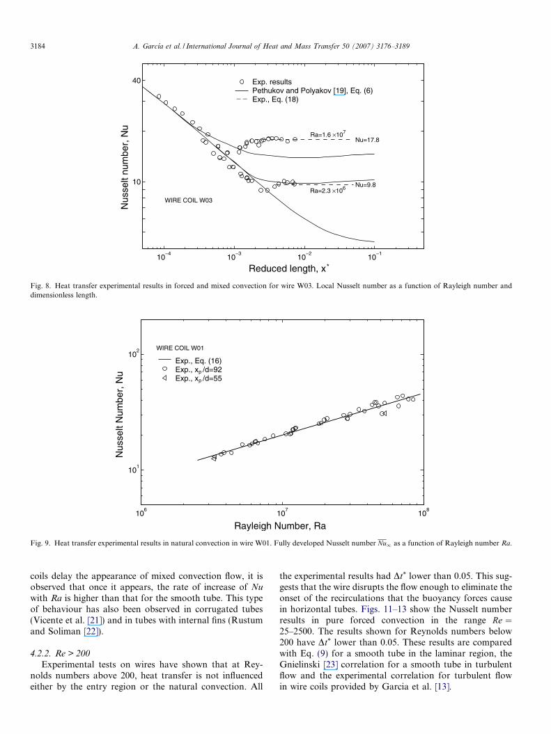
Fig. 8. Heat transfer experimental results in forced and mixed convection for wire W03. Local Nusselt number as a function of Rayleigh number anddimensionless length.
106
107
108
101
102
Rayleigh Number, Ra
Nus
selt
Num
ber,
Nu p
p
Exp., Eq. (16)Exp., x /d=92Exp., x /d=55
WIRE COIL W01
Fig. 9. Heat transfer experimental results in natural convection in wire W01. Fully developed Nusselt number Nu1 as a function of Rayleigh number Ra.
3184 A. Garcıa et al. / International Journal of Heat and Mass Transfer 50 (2007) 3176–3189
coils delay the appearance of mixed convection flow, it isobserved that once it appears, the rate of increase of Nu
with Ra is higher than that for the smooth tube. This typeof behaviour has also been observed in corrugated tubes(Vicente et al. [21]) and in tubes with internal fins (Rustumand Soliman [22]).
4.2.2. Re > 200
Experimental tests on wires have shown that at Rey-nolds numbers above 200, heat transfer is not influencedeither by the entry region or the natural convection. All
the experimental results had Dt* lower than 0.05. This sug-gests that the wire disrupts the flow enough to eliminate theonset of the recirculations that the buoyancy forces causein horizontal tubes. Figs. 11–13 show the Nusselt numberresults in pure forced convection in the range Re ¼25–2500. The results shown for Reynolds numbers below200 have Dt* lower than 0.05. These results are comparedwith Eq. (9) for a smooth tube in the laminar region, theGnielinski [23] correlation for a smooth tube in turbulentflow and the experimental correlation for turbulent flowin wire coils provided by Garcia et al. [13].
106
107
108
101
102
Rayleigh Number, Ra
Nus
selt
Num
ber,
Nu
Wire coil W01, Eq. (16)Wire coil W02, Eq. (17)Wire coil W03, Eq. (18)Smooth tube, Eq. (8)
Fig. 10. Fully developed Nusselt number Nu1 as a function of Rayleigh number Ra. Comparison of results achieved in wires W01–03 and in the smoothtube.
101
102
103
104
101
102
103
Reynolds Number, Re
Nus
selt
Num
ber,
Nu
≈
p
p
p
Pr=640; x /d=27
Pr=575; x /d=55
Pr=485; x /d=92
Pr=360
p
p
p
pExp., x /d=55, Pr 360Smooth tube, Eq. (9) and Ref. [23]
WIRE COIL, TURBULENT FLOW [13] Re0.72 Pr0.37
WIRE COIL W01, p/d=1.25
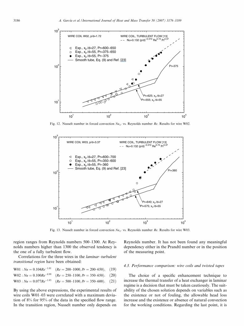
Fig. 11. Nusselt number in forced convection Nucf vs. Reynolds number Re. Results for wire W01.
A. Garcıa et al. / International Journal of Heat and Mass Transfer 50 (2007) 3176–3189 3185
First of all, results obtained for the small pitch wire W01(Fig. 11) are commented in detail. In the fully laminarregion ðRe < 200Þ, results only depend on the entry length.When these are compared to Eq. (9) for the smooth tube,ðNufc ¼ 1:32ðx�Þ�1=3Þ, it is observed that there are basicallyno differences. Results reveal clearly that at Reynolds num-bers between 200 and 1000 there is a laminar–turbulent
transitional region where the wire produces a flow perturba-tion which remarkably increases heat transfer. At Reynoldsnumbers above 1000 the flow is fully turbulent and Nusseltnumber results show the same trend as the one observed by
the authors in their previous paper [13]. At Re ¼ 1000 andPr ¼ 360 the heat transfer exceeds eight times the one thatwould be obtained with a smooth tube at xp=d ¼ 92.
In the intermediate pitch wire W02 (Fig. 12), the Nusseltnumber increases are slightly lower than those of W01.Reynolds numbers at which the transition starts are slightlyhigher. From Re � 1200 on, the flow is fully turbulent.
The large pitch wire W03 performs the lowest heattransfer. Fig. 13 shows that for this wire the smooth tubetendency keeps within a wider Reynolds numbers rangethan in the other two wires, until Re ¼ 500. The transition
101
102
103
104
101
102
103
≈
p
p
pExp., x /d=55, Pr 360Smooth tube, Eq. (9) and Ref. [23]
WIRE COIL, TURBULENT FLOW [13] Re0.72 Pr0.37
WIRE COIL W03, p/d=3.37
p
p
Pr=640; x /d=27
Pr=575; x /d=55
Pr=360
Fig. 13. Nusselt number in forced convection Nucf vs. Reynolds number Re. Results for wire W03.
101
102
103
104
101
102
103
p
p
pExp., x /d=55, Pr ≈ 375Smooth tube, Eq. (9) and Ref. [23]
WIRE COIL, TURBULENT FLOW [13] Re0.72 Pr0.37
WIRE COIL W02, p/d=1.72
p
p
Pr=625; x /d=27
Pr=555; x /d=55
Pr=375
Fig. 12. Nusselt number in forced convection Nucf vs. Reynolds number Re. Results for wire W02.
3186 A. Garcıa et al. / International Journal of Heat and Mass Transfer 50 (2007) 3176–3189
region ranges from Reynolds numbers 500–1300. At Rey-nolds numbers higher than 1300 the observed tendency isthe one of a fully turbulent flow.
Correlations for the three wires in the laminar–turbulent
transitional region have been obtained:
W01 : Nu ¼ 0:104Re�1:01 ðRe ¼ 200–1000; Pr ¼ 200–650Þ; ð19ÞW02 : Nu ¼ 0:100Re�0:99 ðRe ¼ 250–1100; Pr ¼ 350–650Þ: ð20ÞW03 : Nu ¼ 0:077Re�1:03 ðRe ¼ 500–1100; Pr ¼ 350–600Þ: ð21Þ
By using the above expressions, the experimental results ofwire coils W01–03 were correlated with a maximum devia-tion of 8% for 95% of the data in the specified flow range.In the transition region, Nusselt number only depends on
Reynolds number. It has not been found any meaningfuldependency either in the Prandtl number or in the positionof the measuring point.
4.3. Performance comparison: wire coils and twisted tapes
The choice of a specific enhancement technique toincrease the thermal transfer of a heat exchanger in laminarregime is a decision that must be taken cautiously. The suit-ability of the chosen solution depends on variables such asthe existence or not of fouling, the allowable head lossincrease and the existence or absence of natural convectionfor the working conditions. Regarding the last point, it is
A. Garcıa et al. / International Journal of Heat and Mass Transfer 50 (2007) 3176–3189 3187
quite frequent to find researchers or manufacturers whoinform that their enhancement technique increases in sev-eral times the heat transfer with respect to the smooth tubein laminar regime. Authors refer these increases to thesmooth tube in forced convection and obviate that at lowReynolds numbers it is quite likely that the thermal trans-fer would be carried out under mixed convection condi-tions. In warm-up processes, the natural convectionnotably benefits the global heat transfer. This evenincreases up to 5 times in horizontal smooth tubes, withouta pressure drop increase. Except for the familiar techniqueof providing the smooth tube with extended surfaces, the
101
102
100
101
102
103
Reynolds n
Nus
selt
num
ber,
Nu
Ra=1×10⁷
Smooth tube, forced. Eq. (9)Smooth tube, mixed. Eq. (11)Tape y=5, Manglik and Bergles [Tape y=5, Hong and Bergles [7]Wire coil W01, Eqs. (13),(19) and
Nu∞,s
Fig. 14. Nusselt number vs. Reynolds number.
101
102
100
101
102
103
Reynolds n
Nus
selt
num
ber,
Nu
Smooth tube, forced. Eq. (9)Smooth tube, mixed. Eq. (11)Tape y=2.5, Manglik and BerglesTape y=2.5, Hong and Bergles [7Wire coil W01, Eqs. (13),(19) and
Nu∞,s
Ra=1×10⁷
Fig. 15. Nusselt number vs. Reynolds number. W
passive enhancement techniques have little to offer toimprove the heat transfer under free convection conditions(Bergles [24]).
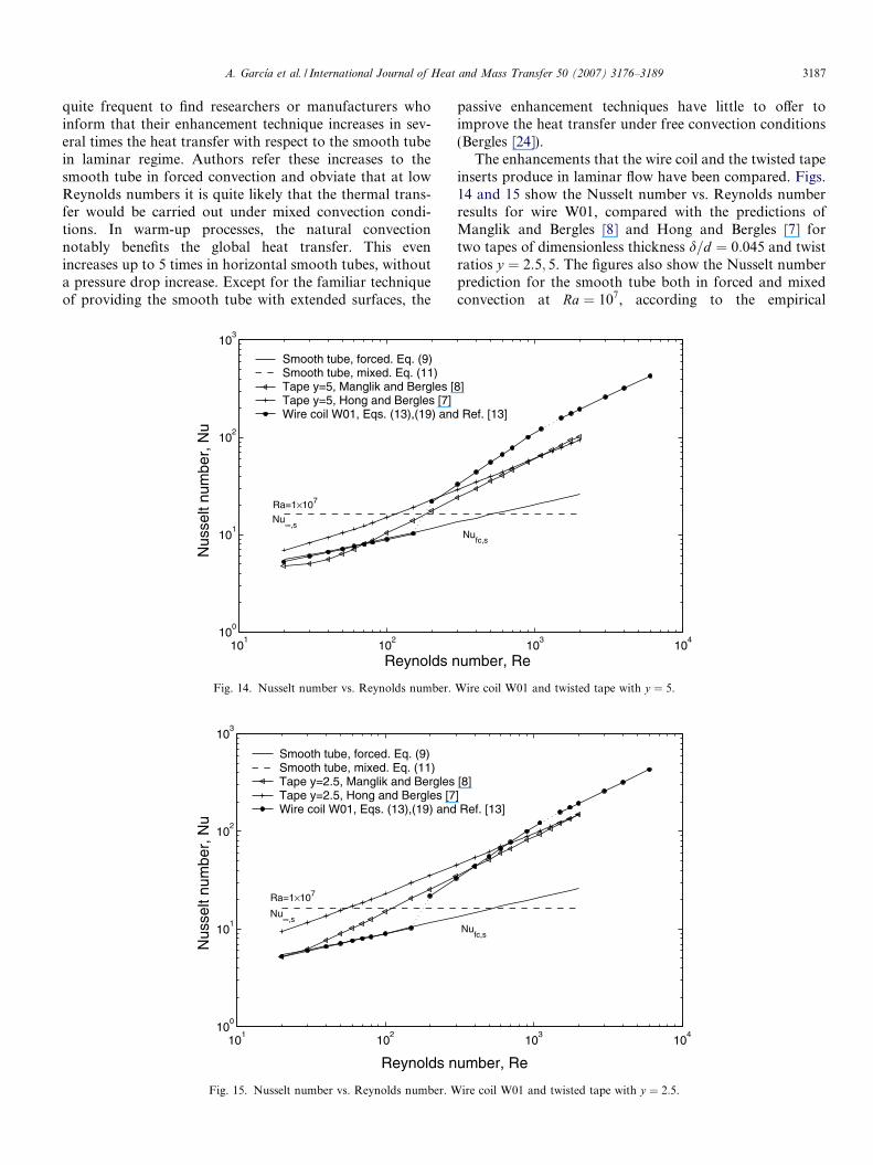
The enhancements that the wire coil and the twisted tapeinserts produce in laminar flow have been compared. Figs.14 and 15 show the Nusselt number vs. Reynolds numberresults for wire W01, compared with the predictions ofManglik and Bergles [8] and Hong and Bergles [7] fortwo tapes of dimensionless thickness d=d ¼ 0:045 and twistratios y ¼ 2:5; 5. The figures also show the Nusselt numberprediction for the smooth tube both in forced and mixedconvection at Ra ¼ 107, according to the empirical
103
104
umber, Re
8]
Ref. [13]
Nufc,s
Wire coil W01 and twisted tape with y ¼ 5.
103
104
umber, Re
[8]] Ref. [13]
Nufc,s
ire coil W01 and twisted tape with y ¼ 2:5.
3188 A. Garcıa et al. / International Journal of Heat and Mass Transfer 50 (2007) 3176–3189
correlations obtained in this paper. The predictions havebeen obtained for a 1 m long horizontal tube, with insidediameter d ¼ 18 mm under the flow conditionsRe ¼ 20–2500 and Pr ¼ 200.
Figs. 14 and 15 show that the twisted tapes behave bet-ter than the wire coils at low Reynolds numbers (Re < 200).In this region a wire coil is almost ineffective. However, theuse of a twisted tape would be clearly counterproductive ifthe smooth tube were under free convection influence at aRayleigh number higher than 107. Here the smooth tubeperformance would get worse if either wire coils or twistedtapes were inserted. Both twisted tapes and wire coilsincrease heat transfer within the Reynolds number rangebetween 200 and 1000. Here wire coil W01 performs betterthan the twisted tape of y ¼ 5; wire W01 and tape ofy ¼ 2:5 increase heat transfer by percentages of the sameorder of magnitude. The latter represents the limits of man-ufacturing of twisted tape inserts, and at Re ¼ 300 has aNusselt number 40% higher than that of the wire W01.The head loss in twisted tapes is always very high: atRe ¼ 300 the friction factor increases f =fs for the wireW01 and twisted tapes of y ¼ 5; 2:5 are 1.3, 3.3 and 4,respectively. At Re ¼ 700 the wire W01 and the twistedtape of y ¼ 2:5 have the same Nusselt number but the pres-sure drop in the tape is almost three times that in the wirecoil.
For Reynolds numbers above Re ¼ 1000, wire coil inserthave higher heat transfer coefficients than any of the twostudied twisted tapes. The difference is essential: whereasfor this Reynolds number in the wire W01 the flow isalready turbulent, in the twisted tapes the flow is still lam-inar. Whereas the twisted tapes delay the transition to tur-bulent flow up to Reynolds numbers higher than those ofthe smooth tube (Manglik and Bergles [8]), the wire coilinserts bring forward it (authors [14]). Even so, the pressuredrop produced by the wire W01 is of the same order thanthe one introduced by any of the two studied twisted tapes.In this range of Reynolds numbers, Oliver and Shoji [10]also observed a better performance of wire coils withrespect to twisted tapes for non-newtonian flows.
5. Conclusions
1. An extensive experimental study on three wires of differ-ent pitch inserted in a smooth tube has been carried out.Laminar and transition regions have been covered. Heattransfer tests have been performed under UHF condi-tions, and the flow ranges have been: Re ¼ 10–2500;Pr ¼ 200–700 and Ra ¼ 3� 106–108. For each wire,experimental correlations of isothermal friction factorand Nusselt number under forced and mixed convectionconditions have been obtained.
2. The friction factor increases in the fully laminar regionlie between 5% and 40%. The transition from laminarflow to turbulent flow is smooth, without the instabilitiesand the pressure drop fluctuations that a smooth tubepresents.
3. The fully laminar region covers up to Re � 200. Here,heat transfer in wire coils can be produced either inforced or in mixed convection. In this region, wire coilsdo not enhance the heat transfer with respect to thesmooth tube.
4. At Reynolds numbers between 200 and 1000, wire coilssignificantly disturb the flow and remarkably increaseheat transfer. The perturbation that the wire bringsabout hinders the establishment of the recirculationsthat the buoyancy forces cause in horizontal tubes,and the heat transfer always takes place in forcedconvection.
5. At Reynolds numbers above Re � 1000–1300 on, wirecoil inserts promote the transition from laminar to tur-bulent flow. The Nusselt number results follow the cor-relation for turbulent flow developed by the authors.The heat transfer increase in this low Reynolds numberregion is very remarkable: in wire W01 at Re ¼ 1000 andPr ¼ 360 the Nusselt number Nu is eight times the one ofa smooth tube with xp=d ¼ 92.
6. Comparison between the experimental results obtainedin wire coils and the most recognized correlations forthe twisted tapes allows to state that both devices areineffective to increase the heat transfer of a smooth tubein mixed convection at Re below 200. At Reynolds num-bers between 200 and 700, both the pressure drop andthe heat transfer increases need to be considered in orderto select one of the two enhancement techniques.Finally, in a smooth tube equipment that works at Rey-nolds numbers between 700 and 2500, the heat transferenhancement obtained with the wire coils will be quitehigher than the one obtained with the twisted tapes.
Acknowledgements
This research has been partially financed by theDPI2003-07783-C02 grant of the ‘‘Direccion General deInvestigacion del Ministerio de Educacion y Ciencia deEspana” and the ‘‘HRS Spiratube” company.
References
[1] A.E. Bergles, Techniques to augment heat transfer, Handbook ofHeat Transfer Applications, second ed., Mc-Graw Hill, New York,1985 (Chapter 1).
[2] R.L. Webb, N.H. Kim, Principles of Enhanced Heat Transfer, seconded., Taylor & Francis Group, New York, 2005.
[3] L. Wang, B. Sunden, Performance comparison of some tube inserts,Int. Commun. Heat Mass Transfer 29 (2002) 45–56.
[4] A. Dewan, P. Mahanta, K. Sumithra Raju, P. Suresh Kumar, Reviewof passive heat transfer augmentation techniques, Proc. Instn. Mech.Engrs., Part A: J. Power Energy 218 (2004) 509–527.
[5] R.M. Manglik, S. Maramraju, A.E. Bergles, The scaling andcorrelation of low Reynolds number swirl flows and friction factorsin circular tubes with twisted tape inserts, J. Enhanced Heat Transfer8 (2001) 383–395.
[6] P.S. Bandyopadhyay, U.N. Gaitonde, S.P. Sukhatme, Influence offree convection on heat transfer during laminar flow in tubes withtwisted tapes, Exp. Therm. Fluid Sci. 4 (1991) 577–586.
A. Garcıa et al. / International Journal of Heat and Mass Transfer 50 (2007) 3176–3189 3189
[7] S.W. Hong, A.E. Bergles, Augmentation of laminar flow heat transferby means of twisted tape inserts, J. Heat Transfer 98 (1976) 251–256.
[8] R.M. Manglik, A.E. Bergles, Heat transfer and pressure dropcorrelations for twisted-tape inserts in isothermal tubes: Part I –laminar flows, J. Heat Transfer 115 (1993) 881–888.
[9] A.E. Bergles, Experimental verification of analyses and correlation ofthe effects of temperature dependent fluid properties on laminar heattransfers, Low Reynolds Number Flow Heat Exchangers, Hemi-sphere, Washington, DC, 1983.
[10] D.R. Oliver, Y. Shoji, Heat transfer enhancement in round tubesusing three different tube inserts: non-newtonian liquids, Trans.IChemE 70 (1992) 558–564.
[11] S.B. Uttarwar, M. Raja Rao, Augmentation of laminar flow heattransfer in tubes by means of wire coil inserts, Trans. ASME 107(1985) 930–935.
[12] H. Inaba, K. Ozaki, S. Kanakoa, A fundamental study of heattransfer enhancement and flow-drag reduction in tubes by means ofwire coil insert, Nippon Kikai Gakkai Ronbunshu, Trans. Jpn. Soc.Mech. Eng. 60 (1994) 240–247.
[13] A. Garcia, P.G. Vicente, A. Viedma, Experimental study of heattransfer enhancement with wire coil inserts in laminar–transition–turbulent regimes at different Prandtl numbers, Int. J. Heat MassTransfer 48 (2005) 4640–4651.
[14] A. Garcia, J.P. Solano, P.G. Vicente, A. Viedma, Flow patternassessment in tubes with wire coil inserts in laminar and transitionregimes, Int. J. Fluid Heat Fluid Flow, in press.
[15] R.K. Shah, A.L. London, Laminar Flow Forced Convection inDucts, Academic Press, New York, 1978.
[16] ISO, Guide to the Expression of Uncertainty in Measurement, firsted., International Organization for Standarization, Switzerland, 1995,ISBN 92-67-10-188-9.
[17] P.G. Vicente, A. Garcia, A. Viedma, Experimental study of mixedconvection and pressure drop in helically dimpled tubes for laminarand transition flow, Int. J. Heat Mass Transfer 45 (2002) 5091–5105.
[18] R.M. Manglik, A.E. Bergles, Heat transfer and pressure dropcorrelations for twisted-tape inserts in isothermal tubes: Part II –transition and turbulent, J. Heat Transfer 115 (1993) 890–896.
[19] B.S. Petukhov, A.F. Polyakov, Heat Transfer in Turbulent MixedConvection, first ed., Hemisphere, New York, 1988.
[20] S.M. Morcos, A.E. Bergles, Experimental investigation of combinedforced and free laminar convection in horizontal tubes, J. HeatTransfer 97 (1975) 212–219.
[21] P.G. Vicente, A. Garcia, A. Viedma, Mixed convection heat transferand isothermal pressure drop in corrugated tubes for laminar andtransition flow, Int. Comm. Heat Mass Transfer 31 (2004) 651–662.
[22] I.M. Rustum, H. Soliman, Experimental investigation of laminarmixed convection in tubes with longitudinal internal fins, J. HeatTransfer 110 (1988) 366–371.
[23] V. Gnielinski, New equations for heat and mass transfer in turbulentpipe and channel flow, Int. Chem. Eng. 16 (1976) 359–368.
[24] A.E. Bergles, ExHFT for fourth generation heat transfer technology,Exp. Them. Fluid Sci. 26 (2002) 335–344.
Related Documents