Enhanced Charge-Transfer Kinetics by Anion Surface Modication of LiFePO 4 Kyu-Sung Park, †,‡ Penghao Xiao, § So-Yeon Kim, ‡ Anthony Dylla, § Young-Min Choi, ‡ Graeme Henkelman, § Keith J. Stevenson, § and John B. Goodenough* ,† † Texas Materials Institute, University of Texas at Austin, Austin, Texas 78712, United States ‡ Battery group, Samsung Advanced Institute of Technology (SAIT), PO Box 111, Suwon 440-600, South Korea § Department of Chemistry and Biochemistry, University of Texas at Austin, Austin, Texas 78712, United States * S Supporting Information ABSTRACT: Despite the great achievement in understanding the materials properties and powder engineering of LiFePO 4 , the chemical bonding at the surface has been almost ignored. Herein, we demonstrate that the undercoordinated Fe 2+ /Fe 3+ redox couple at the surface gives a high barrier for charge transfer, but it can be stabilized by nitrogen or sulfur adsorption. The surface modication improves greatly the charge transfer kinetics and the charge/discharge performance of a LiFePO 4 cathode. Density functional theory (DFT) calculation estimates the origin of the improvement in terms of an electronic and ionic contribution based on a surface model probed by time of ight secondary ion mass spectrometry (TOF- SIMS); the calculation agrees well with an experimental rate-constant analysis. KEYWORDS: Li-ion battery, insertion compounds, interface chemistry ■ INTRODUCTION To reduce the eects of fossil fuels on global warming and air pollution, alternative energy sources at an aordable price are urgently needed. The intermittency of wind and solar energy makes mandatory large-scale energy storage as a complement to these alternative energy sources, and rechargeable batteries can provide both portable and stationary storage of the electrical energy generated from wind and radiant solar power. Moreover, rechargeable batteries that power electric vehicles oer not only a distributed energy store, which can make the cost of battery storage more acceptable, but also a relief from distributed sources of air pollution. LiFePO 4 oers a cathode alternative for a Li-ion battery (LIB) that contains low-cost, environmentally benign materials, is safe, and has a competitive energy density with a proven long cycle life at high rates of charge/discharge. These features make it a worthy target for further reduction of its reversible capacity loss at the highest charge/discharge rates desired for powering an electric vehicle. A LiFePO 4 cathode has a theoretical capacity of 170 mAh g -1 and operates at a voltage of V = 3.45 V versus lithium, which is safely above the HOMO of the organic liquid-carbonate electrolyte. Moreover, the strong covalent bonding within the (PO 4 ) 3- anion keeps the top of the O-2p bands well below the active redox energy, which prevents oxygen evolution at full charge even at high temperatures. 1-4 Although a two-phase reaction between LiFePO 4 and FePO 4 creates a poor electronic conductivity, which lowers the electrochemical capacity at higher charge/discharge rates, carbon coating of nanosized LiFePO 4 particles has largely solved this problem. 5-7 Although Li + diusion is conned to one-dimensional (1-D) channels along the b-axis, 8-10 the nanosized LiFePO 4 particles crystallize in the form of platelets with the b-axis perpendicular to the plates, which facilitates Li access to all the particle volume. With proper quality control, high-rate LiFePO 4 cathodes have been successfully introduced into practical LIBs of very long life. Nevertheless, there is some reversible capacity loss at high rates owing to the resistance of Li + transport across the electrolyte/ electrode interface. We report here a reduction of this charge- transfer resistance by the introduction of nitrogen or sulfur to the surface of the LiFePO 4 particles. We have also undertaken a theoretical study of how the barrier to direct Li + transport between the electrolyte and the b-axis channels is modied by the substitution of nitrogen or sulfur for surface oxygen on the (010) surface plane of the LiFePO 4 platelets. ■ RESULTS AND DISCUSSION Experimental Results. Uncoated LiFePO 4 particles were used to provide clean surfaces for adsorption/chemisorption of N or S. Highly uniform LiFePO 4 powders synthesized hydrothermally by microwave heating were heat-treated further at 600 °C in a reducing atmosphere to ensure the well-ordered surface and bulk structure needed for good electrochemical Received: May 21, 2012 Revised: July 25, 2012 Published: July 26, 2012 Article pubs.acs.org/cm © 2012 American Chemical Society 3212 dx.doi.org/10.1021/cm301569m | Chem. Mater. 2012, 24, 3212-3218

Welcome message from author
This document is posted to help you gain knowledge. Please leave a comment to let me know what you think about it! Share it to your friends and learn new things together.
Transcript
Enhanced Charge-Transfer Kinetics by Anion Surface Modi!cation ofLiFePO4Kyu-Sung Park,†,‡ Penghao Xiao,§ So-Yeon Kim,‡ Anthony Dylla,§ Young-Min Choi,‡
Graeme Henkelman,§ Keith J. Stevenson,§ and John B. Goodenough*,†
†Texas Materials Institute, University of Texas at Austin, Austin, Texas 78712, United States‡Battery group, Samsung Advanced Institute of Technology (SAIT), PO Box 111, Suwon 440-600, South Korea§Department of Chemistry and Biochemistry, University of Texas at Austin, Austin, Texas 78712, United States
*S Supporting Information
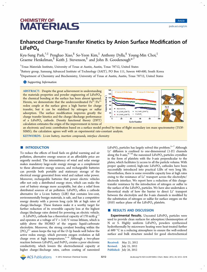
ABSTRACT: Despite the great achievement in understandingthe materials properties and powder engineering of LiFePO4,the chemical bonding at the surface has been almost ignored.Herein, we demonstrate that the undercoordinated Fe2+/Fe3+
redox couple at the surface gives a high barrier for chargetransfer, but it can be stabilized by nitrogen or sulfuradsorption. The surface modi!cation improves greatly thecharge transfer kinetics and the charge/discharge performanceof a LiFePO4 cathode. Density functional theory (DFT)calculation estimates the origin of the improvement in terms ofan electronic and ionic contribution based on a surface model probed by time of "ight secondary ion mass spectrometry (TOF-SIMS); the calculation agrees well with an experimental rate-constant analysis.KEYWORDS: Li-ion battery, insertion compounds, interface chemistry
! INTRODUCTIONTo reduce the e#ects of fossil fuels on global warming and airpollution, alternative energy sources at an a#ordable price areurgently needed. The intermittency of wind and solar energymakes mandatory large-scale energy storage as a complementto these alternative energy sources, and rechargeable batteriescan provide both portable and stationary storage of theelectrical energy generated from wind and radiant solar power.Moreover, rechargeable batteries that power electric vehicleso#er not only a distributed energy store, which can make thecost of battery storage more acceptable, but also a relief fromdistributed sources of air pollution. LiFePO4 o#ers a cathodealternative for a Li-ion battery (LIB) that contains low-cost,environmentally benign materials, is safe, and has a competitiveenergy density with a proven long cycle life at high rates ofcharge/discharge. These features make it a worthy target forfurther reduction of its reversible capacity loss at the highestcharge/discharge rates desired for powering an electric vehicle.A LiFePO4 cathode has a theoretical capacity of 170 mAh g
!1
and operates at a voltage of V = 3.45 V versus lithium, which issafely above the HOMO of the organic liquid-carbonateelectrolyte. Moreover, the strong covalent bonding within the(PO4)
3! anion keeps the top of the O-2p bands well below theactive redox energy, which prevents oxygen evolution at fullcharge even at high temperatures.1!4 Although a two-phasereaction between LiFePO4 and FePO4 creates a poor electronicconductivity, which lowers the electrochemical capacity athigher charge/discharge rates, carbon coating of nanosized
LiFePO4 particles has largely solved this problem.5!7 AlthoughLi+ di#usion is con!ned to one-dimensional (1-D) channelsalong the b-axis,8!10 the nanosized LiFePO4 particles crystallizein the form of platelets with the b-axis perpendicular to theplates, which facilitates Li access to all the particle volume. Withproper quality control, high-rate LiFePO4 cathodes have beensuccessfully introduced into practical LIBs of very long life.Nevertheless, there is some reversible capacity loss at high ratesowing to the resistance of Li+ transport across the electrolyte/electrode interface. We report here a reduction of this charge-transfer resistance by the introduction of nitrogen or sulfur tothe surface of the LiFePO4 particles. We have also undertaken atheoretical study of how the barrier to direct Li+ transportbetween the electrolyte and the b-axis channels is modi!ed bythe substitution of nitrogen or sulfur for surface oxygen on the(010) surface plane of the LiFePO4 platelets.
! RESULTS AND DISCUSSIONExperimental Results. Uncoated LiFePO4 particles were
used to provide clean surfaces for adsorption/chemisorption ofN or S. Highly uniform LiFePO4 powders synthesizedhydrothermally by microwave heating were heat-treated furtherat 600 °C in a reducing atmosphere to ensure the well-orderedsurface and bulk structure needed for good electrochemical
Received: May 21, 2012Revised: July 25, 2012Published: July 26, 2012
Article
pubs.acs.org/cm
© 2012 American Chemical Society 3212 dx.doi.org/10.1021/cm301569m | Chem. Mater. 2012, 24, 3212!3218

properties.11,12 After the heat-treatment, the bare LiFePO4particles were single-phased with lattice parameters a =10.321(1), b = 6.0021(5), and c = 4.6904(5) nm; and theparticle size varied from 100 to 500 nm owing to particlesintering at 600 °C (see the Supporting Information formaterials characterization, Figures S1!S5). To introducenitrogen to the surface, the bare LiFePO4 particles werepostannealed under a NH3 atmosphere at various temperaturesfrom 300 to 500 °C. To introduce sulfur, bare LiFePO4 powderwas exposed to sulfur vapor at 400 °C and subsequentlyannealed at 400 °C in a pure vacuum to remove elementalsulfur from the surface. The surfaces of bare LiFePO4 andFePO4 particles were modi!ed by NH3 gas and S vapor, andthese surface-modi!ed samples are denoted N-LiFePO4, N-FePO4, and S-LiFePO4, S-FePO4, respectively.The particle size and the morphology were little changed by
the postannealing treatments, regardless of the annealingtemperatures; changes in the lattice parameters are also lessthan 0.05% compared to the reference values. Three Ramanbands observed above 400 cm!1 for both the bare and N-LiFePO4 samples are due to intramolecular (PO4)
3! symmetric(951 cm!1) and asymmetric (996 and 1068 cm!1) stretchingvibrations (Figure S5, Supporting Information). Raman bandslocated in the 100!400 cm!1 region are typically assigned totranslatory intermolecular modes involving lattice vibrations of(PO4)
3! units and Fe2+ ions.13 These modes are often weak anddi$cult to assign correctly. The lack of peaks in the 1200!1700cm!1 region related to the broad D and G modes of graphiteindicate that there was no carbon coating of the particle surfaceor heterogeneously mixed with the LiFePO4 crystallites.Previous studies have observed a broadening of the intra-molecular symmetric stretching mode of (PO4)
3! in LiFePO4that can be attributed to a lower degree of order in the latticeowing to doping of other transition metals.13 While aliovalentdoping was not used in this study, signi!cant di#usion ofnitrogen or sulfur into the bulk of LiFePO4 may similarly beexpected to distort the crystal structure. No broadening wasobserved in the intramolecular (PO4)
3! mode at 951 cm!1 forthe N-LiFePO4 compared to the reference material. This result,along with X-ray di#raction (XRD), shows that the bulk of theN-LiFePO4 remains unchanged. The Raman spectrum of S-LiFePO4 also shows bands normally associated with LiFePO4,which suggests that the LiFePO4 structure is preserved uponsulfur exposure. Several bands not associated with LiFePO4 arealso present. The bands at 320, 339, and 374 cm!1 are likelyassociated with surface-bound Fe!S species.14
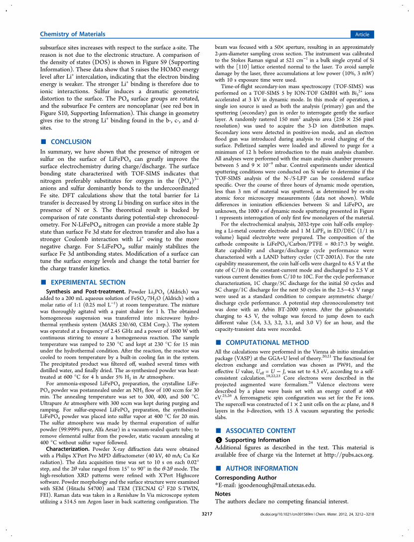
Time of "ight secondary ion mass spectrometry (TOF-SIMS) was used to interrogate the surface layer of N- and S-LiFePO4 to con!rm the presence of N and S elements and todetermine the relative depth of their distribution. Figure 1ashows depth pro!les for various temperature treatments of N-LiFePO4 along with the reference material. A major ionicspecies had P!N bonds; surface adsorbed NH3
+ and NH4+ ions
gave a signi!cantly smaller signal intensity. Theoreticalcalculation also supports the N-replacement of O in the(PO4)
3! unit; therefore, ion fragments containing subspecies ofthat polyatomic ion should be an accurate marker for detectionof surface nitrogen. Finally, the sum of PN+ and PNH2
+ wereselected as the surface nitridation ions to construct the depthpro!les. The two-dimensional (2-D) pro!le for the bareLiFePO4 shows that there is a small amount of N-species, butthe concentration is signi!cantly lower near the surfacecompared to NH3-treated LiFePO4 samples. For the N-
LiFePO4 prepared at 300 °C, the initial concentration islower than both the 400 and 500 °C samples but above that ofthe bare LiFePO4, indicating surface nitridation. The N-LiFePO4 prepared at 400 °C has the highest relativeconcentration of N-species at the surface while the signalsharply drops to a baseline level at deeper depths suggestingthat the N-species are con!ned to the surface. Finally, the N-LiFePO4 prepared at 500 °C exhibits the second-highestrelative N-species concentration at the surface, but the signalpro!le is signi!cantly more di#use throughout the depthpro!ling experiment. This observation indicates that degrada-tion of the material at the surface and near surface is occurringowing to the higher reaction temperature, which leads tofurther di#usion of nitrogen into the particle,15 as is also clearlyshown in the high-resolution TEM images (Figure S4,Supporting Information).Figure 1b shows similar depth pro!les comparing the bare
LiFePO4 to the S-LiFePO4. In this case, the major ion specieshave Fe!S bonds, and theoretical calculation also con!rms thatsulfur atoms prefer to bond at dangling surface Fe sites. Thepresence of elemental sulfur can be excluded because it brings ahigh-voltage decomposition. After annealing under sulfur vapor,the material shows an electrochemical decomposition at around4.45 V vs Li+/Li, but this feature disappears after a followinganneal under pure vacuum. Therefore, we investigated FeS+ andFeSH+ ion fragments as indicators of surface sulfur interactions.In contrast to the N-LiFePO4, the concentration pro!le of S-LiFePO4 in the surface layer is more di#use and of higherrelative concentration compared to the bare LiFePO4. This
Figure 1. TOF-SIMS depth pro!les, with Bi32+ sputtering, of (a) the
sum of PN+ and PNH2+ ion species for N-LiFePO4 and (b) the sum of
FeS+ and FeSH+ ion fragments for S-LiFePO4. Inset images in a and bshow areal distributions of the PN+/PNH2
+ ions for N-LiFePO4prepared at 400 °C and the FeS+/FeSH+ ions for S-LiFePO4,respectively.
Chemistry of Materials Article
dx.doi.org/10.1021/cm301569m | Chem. Mater. 2012, 24, 3212!32183213

observation suggests that sulfur reacts di#erently at theLiFePO4 surface than nitrogen and is consistent with thetheoretical lowest-energy surface calculations showing Fe!Sbonding as opposed to P!N bonding. Knock-in e#ects by thebombardment of the surface with Bi3
2+ clusters may also explainthe more di#use nature of the 2-D pro!le for S-LiFePO4. Sincethe FeS-related species are heavier, it is likely that a higherproportion of those species relative to the lighter PN-relatedspecies will be pushed into the surface rather than ejected intothe mass analyzer; therefore, a more broad relative concen-tration pro!le would be observed. Results from the TOF-SIMSanalysis show that both nitrogen and sulfur bond at the surfaceof LiFePO4, but do not di#use signi!cantly into the bulk of thecrystal. Though we cannot quantify the sputtering depth, we arecon!dent that we are only interrogating the surface layers basedon the low dose of Bi3
2+ sputtering used in dynamic-modeoperation.Electrochemical properties of the surface-modi!ed LiFePO4
have been characterized by the discharge-rate capability andhigh-rate cycling tests at room temperature shown in Figure 2
(see also Supporting Information, Figure S6). The bareLiFePO4 discharge speci!c capacity is 149.9 mAh g!1 at a C/10 rate, it falls to 28.2 mAh g!1 at 10C. However, afterintroducing N onto the surface at 400 °C, the capacity at 10C issigni!cantly increased to 78.9 mAh g!1, while the 300 °Cannealing shows negligible di#erence in the rate capability.Considering the higher amount of nitrogen on the particlesurface after the 400 °C annealing, the data suggests thatnitrogen can signi!cantly in"uence the interfacial charge-
transfer kinetics. After 500 °C annealing, however, the capacityis lowered to 147 mAh g!1 at C/10, but it still has a better rateperformance than that of the bare LiFePO4. The initial capacitydecrease is consistent with the high-resolution TEM and TOF-SIMS data that showed a surface decomposition at 500 °Cowing to a highly reducing condition, but the presence ofnitrogen still has a positive e#ect on the discharge kinetics. Forthe sulfur-introduced LiFePO4, the capacity at C/10 is 152.6mAh g!1, and at higher current densities, it shows better ratecapability than that of N-LiFePO4. At the 10C rate, the capacityof S-LiFePO4 is 86.4 mAh g!1. Sulfur on the surface hasbrought a strong positive e#ect on the rate performance that iscomparable to that of the N-LiFePO4 prepared at 400 °C.Asymmetric charge/discharge cycling also gives an interest-
ing result (Figure 2b). 1C charge followed by a 5C dischargecon!rms the great di#erence in the high-rate capacities betweenbare and N-/S-LiFePO4 half-cells. The capacity trend in the!rst cycling condition is similar to that of the rate performanceresult: S-LiFePO4 and N-LiFePO4 prepared at 400 °C showaverage capacities of 99.1 and 97.9 mAh g!1, respectively; thebare LiFePO4 has 61.4 mAh g!1. After changing the charge/discharge current densities in the reverse condition (5C chargeand the following 1C discharge), the discharge capacitygenerally drops in every case, which should be due to lesscharging capacity at the higher current, 5C. From the result, it isclear that N-/S-LiFePO4 cells have less capacity drop;strikingly, the drop almost disappeared in the case of S-LiFePO4 and N-LiFePO4 prepared at 400 °C. The surfacemodi!cation by N and S atoms enhances signi!cantly not onlythe discharge rate-performance but also the charging kinetics.
Theoretical Results. Since calculation has indicated a highactivation energy for Li+ surface di#usion,16 we have studiedhow the barrier to direct Li+ transport between the electrolyteand the b-axis channels can be modi!ed by nitrogen or sulfursurface species. In such a study, it is important to identify thecharacteristics of the surface (010) plane. The strong covalentbonding of the (PO4)
3! anion makes it reasonable to assumethat it is the Li and/or Fe sites that become undercoordinatedat the surface as recently calculated for a relaxed surface (010)plane.17 However, an exposure to NH3, P!N bonds may formas a result of loss of oxygen from the (PO4)
3! groups.Undercoordination of the Fe changes the Fe3+/Fe2+ redoxenergy both at and a little below the (010) surface, and thesechanges can be modi!ed by chemisorption of di#erent anionspecies on the surface. Among the anions that can replacesurface oxygen or (PO4)
3! anions, nitrogen and sulfur(respective electronic con!guration: [He]2s22p3 and [Ne]-3s23p4) are particularly interesting because each atom has adi#erent ionic size, formal charge, and electronegativity.To correlate the presence of N and S atoms on the speci!c
surface sites and the improved electrochemical properties,density functional theory (DFT) calculations of the surface-modi!ed FePO4 have been performed. TOF-SIMS results showthat N and S appear only on the surface of LiFePO4; nitrogen isfound mainly with phosphorus as P!N, while sulfur is foundwith iron as Fe!S. Using these results as guidance, we replacedan O atom closest to a b-channel with a nitrogen atom in a PO4group in the N-LiFePO4 case; in the S-LiFePO4 case, we put asulfur atom on top of a surface Fe site, forming a Fe!S bond.These binding sites were found to be energetically favorable.Figure 3 shows the calculated binding energy of a single Li+
ion as it di#uses from the (010) surface of FePO4 along the b-channel. In the bare FePO4, Li
+ binds weakly on the surface and
Figure 2. (a) Discharge rate capability of the bare and N-/S-LiFePO4half-cells evaluated after C/10 charging to 4.5 V vs Li+/Li in eachcycle. (b) Discharge capacities at the asymmetric charge/dischargecycling conditions. The !rst 50 cycles were tested at 1C charge/5Cdischarge in 2.5!4.5 V range, and after that, the current densities werereversed.
Chemistry of Materials Article
dx.doi.org/10.1021/cm301569m | Chem. Mater. 2012, 24, 3212!32183214

subsurface sites (a- and b-sites, respectively) owing to a lowcoordination of Li and Fe on the surface and a structuraldistortion of the subsurface site. Where Li+ reaches an FePO4bulk site, the binding is stronger by 0.18 eV. Li binds moststrongly in the LiFePO4 phase. In the FePO4 phase, there is aCoulomb attraction between Li+ and its electron, which islocated on a neighboring Fe2+ center. In the LiFePO4 phase,several Li+ can share the same Fe2+ center making the Coulombenergy correspondingly lower. The binding energies for thethree regions (surface, FePO4, and LiFePO4) are !3.10, !3.28,and !3.75 eV, respectively, consistent with values reported inthe literature.16,17
Since the barriers for Li hopping between sites are relativelysmall (0.2!0.3 eV) and do not vary signi!cantly betweenphases,16,18 the binding energies along the b-channel can serveas the minimum energy path (MEP) for Li di#usion into andout of the material. As shown in Figure 3, the weak binding ofLi to the surface site determines the overall barrier for bothlithiation and delithiation. Theoretically, if the voltage is below3.75 V during lithiation, Li should be able to intercalate into thecathode and form the LiFePO4 phase. In practice, however, therate at this voltage is too low to be measured. There are tworeasons for this observation: !rst, di#usion of Li+ into thematerial has to overcome a relatively high barrier (3.75 ! 3.10= 0.65 eV), and second, those intercalating Li+ mustagglomerate to nucleate the LiFePO4 phase. Only when thevoltage approaches 3.28 V does the discharge current become
measurable because at this voltage, isolated Li+ ions are stablein the FePO4 phase. Both N- and S-modi!cation decrease thetotal barrier by strengthening the Li+ binding on surface sites,thus improving the rate performance. After the surfacemodi!cation, the barrier is determined by the Li+ bindingenergy in the FePO4 bulk phase.Focusing on the lithiation (discharge) processes, we can
compare the rate of the bare and N-/S-FePO4 to see whetherexperimental discharging rates match what we expect from thecalculated energy landscape (Figure 3). If the anode energylevel increases (by decreasing the applied voltage betweenanode and cathode), the overall lithiation barrier height willchange. If the anode energy level is below that of the weakestbinding site, the intercalation barrier is the energy di#erencebetween these two sites. If the anode energy level is above theweakest binding site energy, there is no additional barrier abovethe di#usion barrier between sites, and so, the intercalation rateis limited by di#usion (or other mass transport factors in theexperimental apparatus).We take the di#usion barrier in this high-energy anode
regime to be the barrier for Li+ transport from the anode to thesurface site, denoted !EN for the N-FePO4 and !E for the bareFePO4. !EN and !E are independent of the applied voltage.Next, we denote the binding energy of Li+ in a bulk site of N-FePO4 as EN, and the surface site binding energy of the bareFePO4 as E. EN and E are the binding energies of Li at thehighest energy (weakest binding) sites for the N-FePO4 and the
Figure 3. Energy landscapes of Li moving from the surface into the b-channel of bare FePO4 and in the presence of N and S. Inset crystallographicimages represent the structural modi!cation forming N!P and Fe!S bonds after introducing N and S atoms on the surface.
Chemistry of Materials Article
dx.doi.org/10.1021/cm301569m | Chem. Mater. 2012, 24, 3212!32183215

bare FePO4, respectively. The relative rate constants for thebare and N-FePO4 cases follow eq 1. Here, we assume the sameprefactor A for all the lithiation processes and use V! as aconverted value of the applied voltage in eV scale (V! = !V invalue).
! < = =
< ! <= =
! > = =
!
!!
!
!!
!
!!
" " !
" " !" "
" " !
" #" "# " !
" #
" #" # "#
V E kk
AA
E V Ekk
AA
V E kk
AA
(I) : ee
e
(II) :ee
e
(III) : ee
e
N
E V
E VE E
E V
EE E V
E
EE E
N
( )
( )( )
N
N
( )
( )( )
N
( )
( )( )
N
N
N
N
N
N
(1)
As shown in eq 1, if V! < EN and V! > E (regions I and III),the ratio of rate constants is constant, while in between theratio increases as the voltage decreases (V! increases). In the!rst region, V! < EN, the current is too small to be measured inexperiment, as discussed; in the third region, V! > E, the voltageis too high and the system is far from equilibrium, which maycomplicate the discussion. So we will compare with theexperiment the rate constant trend for EN < V < E in region II.These same arguments hold for the dependence of rate on
the applied voltage in the S-FePO4.A potential step chronocoulometry was performed to
evaluate the calculated energy barriers according to eq 1(II)(see Supporting Information, Figure S7). To estimate the rateconstant, k, from the experimental data, we assumed thelithiation process to be a simple !rst-order reaction. Becauselithium-ion di#usion into the cathode is equivalent to vacanciesmoving out, the rate equation is written in terms of vacancyconcentration CV. The backward reaction can be ignored whenthe discharge time, t, is small.
= "C tt
kC td ( )d
( )VV (2)
= "C t C( ) (0) e ktV V (3)
Converting CV to the capacity, Q.
$ " = $ "Q Q t Q( ) ( ) ( ) e kt (4)
" $ = "!"#
$%&
Q tQ
ktln 1 ( )( ) (5)
ln(1 ! Q(t)/Q(")) vs time curves of the bare and N-/S-FePO4 are found to be linear in the short-time domain asshown in Figure S7 (Supporting Information).19 In this short-time domain, the discharge reaction is interfacial charge-transfercontrolled, not di#usion-controlled. From the curve, the ratio ofthe rate constants of the bare and N-/S-FePO4 are plotted inFigure 4 to show the voltage-dependent variation as predictedfrom eq 1. The experimental trend clearly con!rms thecalculation. In both N- and S-FePO4 cells, as the applied voltagedecreases, the k/kN and k/kS ratio increases. At around 3.2 and3.1 V, it reaches a plateau, where the ratio stops increasing asthe voltage decreases (a transition between region II and III,where the lithium binding energy E = !3.10 eV). Since sulfurhas a higher surface coverage than N, as shown in Figure 1, theslope of k/kS may be higher than k/kN of N-FePO4. Moreover,
regardless of the voltage values, the rate constants of N-/S-FePO4 are always higher than that of the bare FePO4, whichmust enhance the high-rate performance of the electrochemicalcell.In this section, we discuss changes to the Li binding due to
surface doping. The Li binding energy has two primarycontributions: the electronic part (e!) and the ionic part (Li+).For the bare FePO4, weak binding at the surface is primarilydue to the electronic contribution. In the bulk, the Fe dz
2
orbital extends over two neighboring oxygen atoms; on thesurface, Fe is undercoordinated, and its dz
2 orbital extends overonly one oxygen neighbor. The surface Fe!O bond is,therefore, stronger, and the energy of the correspondingantibonding state (populated by the extra electron from Li) ishigher. In the b-site of Figure 3, the ionic part is responsible forweak binding. Li+ in the site is fully coordinated, but the cagespace where Li+ can sit is bigger than in a bulk site. Thedistance between Li+ and half of the surrounding O2! isincreased, raising the Coulombic energy. In the a-site of Figure3, Li+ is missing an attractive interaction from an O2! center; itis also missing a repulsion interaction from an Fe3+ center. As aresult of these two competing e#ects (which are comparable inmagnitude), the ionic contribution of Li+ binding to an a-site iscomparable to a bulk FePO4 site.N-substitution can stabilize Li+ in both a- and b-sites because
it a#ects the binding energies in both the electronic part andthe ionic part. First, as shown in Figure S8 (SupportingInformation), nitrogen provides an empty 2p state in the bandgap, so that the extra electron coming with Li+ does not have togo to the higher energy Fe 3d states. Nitrogen lowers theHOMO energy after Li intercalation. Second, nitrogen is morenegatively charged than oxygen and has a stronger Coulombinteraction with Li+. Comparison of the atomic structures of a-,b-, and c-sites are shown in Figure S10 (SupportingInformation). As can be seen, Li+ in the b-site is displacedtoward the nitrogen, as compared to the b-site in the barematerial, showing the attractive interaction.An analysis of the S-doped surface shows that the mechanism
for increasing Li+ binding is di#erent from that of nitrogen.Sulfur binds directly to a surface Fe atom, providing fullcoordination of the Fe center. The electronic environment ofLi+ is similar to that in the bulk and the binding energy is closeto that of Li in bulk FePO4. The binding of Li
+ in the b- and c-
Figure 4. Ratio of the rate constants between the bare and N-/S-LiFePO4. The rate equation is estimated in terms of !lling up vacantLi-sites in FePO4 during constant-voltage discharge by the equationln(1 ! Q(t)/Q(")) = !kt.
Chemistry of Materials Article
dx.doi.org/10.1021/cm301569m | Chem. Mater. 2012, 24, 3212!32183216
subsurface sites increases with respect to the surface a-site. Thereason is not due to the electronic structure. A comparison ofthe density of states (DOS) is shown in Figure S9 (SupportingInformation). These data show that S raises the HOMO energylevel after Li+ intercalation, indicating that the electron bindingenergy is weaker. The stronger Li+ binding is therefore due toionic interactions. Sulfur induces a dramatic geometricdistortion to the surface. The PO4 surface groups are rotated,and the subsurface Fe centers are noncoplanar (see red box inFigure S10, Supporting Information). This change in geometrygives rise to the strong Li+ binding found in the b-, c-, and d-sites.
! CONCLUSIONIn summary, we have shown that the presence of nitrogen orsulfur on the surface of LiFePO4 can greatly improve thesurface electrochemistry during charge/discharge. The surfacebonding state characterized with TOF-SIMS indicates thatnitrogen preferably substitutes for oxygen in the (PO4)
3!
anions and sulfur dominantly bonds to the undercoordinatedFe site. DFT calculations show that the total barrier for Litransfer is decreased by strong Li binding on surface sites in thepresence of N or S. The theoretical result is backed bycomparison of rate constants during potential-step chronocoul-ometry. For N-LiFePO4, nitrogen can provide a more stable 2pstate than surface Fe 3d state for electron transfer and also has astronger Coulomb interaction with Li+ owing to the morenegative charge. For S-LiFePO4, sulfur mainly stabilizes thesurface Fe 3d antibonding states. Modi!cation of a surface cantune the surface energy levels and change the total barrier forthe charge transfer kinetics.
! EXPERIMENTAL SECTIONSynthesis and Post-treatment. Powder Li3PO4 (Aldrich) was
added to a 200 mL aqueous solution of FeSO4·7H2O (Aldrich) with amolar ratio of 1:1 (0.25 mol L!1) at room temperature. The mixturewas thoroughly agitated with a paint shaker for 1 h. The obtainedhomogeneous suspension was transferred into microwave hydro-thermal synthesis system (MARS 230/60, CEM Corp.). The systemwas operated at a frequency of 2.45 GHz and a power of 1600 W withcontinuous stirring to ensure a homogeneous reaction. The sampletemperature was ramped to 230 °C and kept at 230 °C for 15 minunder the hydrothermal condition. After the reaction, the reactor wascooled to room temperature by a built-in cooling fan in the system.The precipitated product was !ltered o#, washed several times withdistilled water, and !nally dried. The as-synthesized powder was heat-treated at 600 °C for 4 h under 5% H2 in Ar atmosphere.For ammonia-exposed LiFePO4 preparation, the crystalline LiFe-
PO4 powder was postannealed under an NH3 "ow of 100 sccm for 30min. The annealing temperature was set to 300, 400, and 500 °C.Ultrapure Ar atmosphere with 300 sccm was kept during purging andramping. For sulfur-exposed LiFePO4 preparation, the synthesizedLiFePO4 powder was placed into sulfur vapor at 400 °C for 20 min.The sulfur atmosphere was made by thermal evaporation of sulfurpowder (99.999% pure, Alfa Aesar) in a vacuum-sealed quartz tube; toremove elemental sulfur from the powder, static vacuum annealing at400 °C without sulfur vapor followed.Characterization. Powder X-ray di#raction data were obtained
with a Philips X’Pert Pro MPD di#ractometer (40 kV, 40 mA; Cu K!radiation). The data acquisition time was set to 10 s on each 0.02°step, and the 2" value ranged from 15° to 90° in the "-2" mode. Thehigh-resolution XRD patterns were re!ned with X’Pert Highscoresoftware. Powder morphology and the surface structure were examinedwith SEM (Hitachi S4700) and TEM (TECNAI G2 F20 S-TWIN,FEI). Raman data was taken in a Renishaw In Via microscope systemutilizing a 514.5 nm Argon laser in back scattering con!guration. The
beam was focused with a 50! aperture, resulting in an approximately2-#m-diameter sampling cross section. The instrument was calibratedto the Stokes Raman signal at 521 cm!1 in a bulk single crystal of Siwith the [110] lattice oriented normal to the laser. To avoid sampledamage by the laser, three accumulations at low power (10%, 3 mW)with 10 s exposure time were used.
Time-of-"ight secondary-ion mass spectroscopy (TOF-SIMS) wasperformed on a TOF-SIMS 5 by ION-TOF GMBH with Bi3
2+ ionsaccelerated at 3 kV in dynamic mode. In this mode of operation, asingle ion source is used as both the analysis (primary) gun and thesputtering (secondary) gun in order to interrogate gently the surfacelayer. A randomly rastered 150 mm2 analysis area (256 ! 256 pixelresolution) was used to acquire the 3-D ion distribution maps.Secondary ions were detected in positive-ion mode, and an electron"ood gun was introduced during analysis to avoid charging of thesurface. Pelletized samples were loaded and allowed to purge for aminimum of 12 h before introduction to the main analysis chamber.All analyses were performed with the main analysis chamber pressuresbetween 5 and 9 ! 10!9 mbar. Control experiments under identicalsputtering conditions were conducted on Si wafer to determine if theTOF-SIMS analysis of the N-/S-LFP can be considered surfacespeci!c. Over the course of three hours of dynamic mode operation,less than 3 nm of material was sputtered, as determined by ex-situatomic force microscopy measurements (data not shown). Whiledi#erences in ionization e$ciencies between Si and LiFePO4 areunknown, the 1000 s of dynamic mode sputtering presented in Figure1 represents interrogation of only !rst few monolayers of the material.
For the electrochemical analysis, 2032-type coin half-cells employ-ing a Li-metal counter electrode and 1 M LiPF6 in ED/DEC (1/1 involume) liquid electrolyte were prepared. The composition of thecathode composite is LiFePO4/Carbon/PTFE = 80:17:3 by weight.Rate capability and charge/discharge cycle performance werecharacterized with a LAND battery cycler (CT-2001A). For the ratecapability measurement, the coin half-cells were charged to 4.5 V at therate of C/10 in the constant-current mode and discharged to 2.5 V atvarious current densities from C/10 to 10C. For the cycle performancecharacterization, 1C charge/5C discharge for the initial 50 cycles and5C charge/1C discharge for the next 50 cycles in the 2.5!4.5 V rangewere used as a standard condition to compare asymmetric charge/discharge cycle performance. A potential step chronocoulometry testwas done with an Arbin BT-2000 system. After the galvanostaticcharging to 4.5 V, the voltage was forced to jump down to eachdi#erent value (3.4, 3.3, 3.2, 3.1, and 3.0 V) for an hour, and thecapacity-transient data were recorded.
! COMPUTATIONAL METHODAll the calculations were performed in the Vienna ab initio simulationpackage (VASP) at the GGA+U level of theory.20,21 The functional forelectron exchange and correlation was chosen as PW91, and thee#ective U value, Ueff = U ! J, was set to 4.3 eV, according to a self-consistent calculation.18,22,23 Core electrons were described in theprojected augmented wave formalism.24 Valence electrons weredescribed by a plane wave basis set with an energy cuto# at 400eV.25,26 A ferromagnetic spin con!guration was set for the Fe ions.The supercell was constructed of 1 ! 2 unit cells on the ac plane, and 8layers in the b-direction, with 15 Å vacuum separating the periodicslabs.
! ASSOCIATED CONTENT*S Supporting InformationAdditional !gures as described in the text. This material isavailable free of charge via the Internet at http://pubs.acs.org.
! AUTHOR INFORMATIONCorresponding Author*E-mail: [email protected] authors declare no competing !nancial interest.
Chemistry of Materials Article
dx.doi.org/10.1021/cm301569m | Chem. Mater. 2012, 24, 3212!32183217

! ACKNOWLEDGMENTSThis material is primarily based upon work supported as part ofthe program “Understanding Charge Separation and Transferat Interfaces in Energy Materials (EFRC:CST)”, an EnergyFrontier Research Center funded by the U.S. Department ofEnergy, O$ce of Science, O$ce of Basic Energy Sciencesunder Award No. DE-SC0001091. TOF-SIMS data wereacquired on a TOF-SIMS 5 instrument (ION-TOF GmbH,Germany, 2010) purchased through the National ScienceFoundation Major Research Instrumentation program (DMR-0923096).
! DEDICATIONHis co-authors would like to congratulate Prof. John B.Goodenough on the occasion of his 90th birthday.
! REFERENCES(1) Padhi, A. K.; Nanjundaswamy, K. S.; Goodenough, J. B. J.Electrochem. Soc. 1997, 144, 1188.(2) Yuan, L.-X.; Wang, Z.-H.; Zhang, W.-X.; Hu, X.-L.; Chen, J.-T.;Huang, Y.-H.; Goodenough, J. B. Energy Environ. Sci. 2011, 4, 269.(3) Yamada, A.; Chung, S.; Hinokuma, K. J. Electrochem. Soc. 2001,148, A224.(4) Ong, S. P.; Jain, A.; Hautier, G.; Kang, B.; Ceder, G. Electrochem.Commun. 2010, 12 (3), 427.(5) Ravet, N.; Goodenough, J. B.; Besner, S.; Simoneau, M.;Hovington, P.; Armand, M. Abstract no. 127. 196th Meeting of theElectrochemical Society, 1999.(6) Ravet, N.; Chouinard, Y.; Magnan, J. F.; Besner, S.; Gauthier, M.;Armand, M. J. Power Sources 2001, 97!98, 503.(7) Huang, H.; Yin, S.-C.; Nazar, L. F. Electrochem. Solid State Lett2001, 4 (10), A170.(8) Nishimura, S.-I.; Kobayashi, G.; Ohoyama, K.; Kanno, R.;Yashima, M.; Yamada, A. Nat. Mater. 2008, 7, 707.(9) Morgan, D.; der Ven, A. V.; Ceder, G. Electrochem. Solid StateLett. 2004, 7, A30.(10) Islam, M.; Driscoll, D.; Fisher, C.; Slater, P. Chem. Mater. 2005,17, 5085.(11) Whittingham, M. S. Chem. Rev. 2004, 104, 4271.(12) Trudeau, M. L.; Laul, D.; Veillette, R.; Serventi, A. M.; Mauger,A.; Julien, C. M.; Zaghib, K. J. Power Sources 2011, 196, 7383.(13) Bai, Y.; Yin, Y.; Yang, J.; Qing, C.; Zhang, W. J. Raman Spectrosc.2011, 42, 831.(14) Susac, D.; Zhu, L.; Teo, M.; Sode, A.; Wong, K. C.; Wong, P. C.;Parsons, R. R.; Bizzotto, D.; Mitchell, K. A. R.; Campbell, S. A. J. Phys.Chem. C 2007, 111, 18715.(15) Ellis, B.; Subramanya Herle, P.; Rho, Y.-H.; Nazar, L. F.;Dunlap, R.; Perry, L. K.; Ryan, D. H. Faraday Discuss. 2007, 134, 119.(16) Dathar, G. K. P.; Sheppard, D.; Stevenson, K. J.; Henkelman, G.Chem. Mater. 2011, 23 (17), 4032.(17) Wang, L.; Zhou, F.; Meng, Y. S.; Ceder, G. Phys. Rev. B 2007,76, 165435.(18) Maxisch, T.; Zhou, F.; Ceder, G. Phys. Rev. B 2006, 73, 104301.(19) Montella, C. J. Electroanal. Chem. 2002, 518, 61.(20) Kohn, W.; Sham, L. J. Phys. Rev. 1965, 140, A1133.(21) Kohn, W.; Becke, A. D.; Parr, R. G. J. Phys. Chem. 1996, 100,12974.(22) Perdew, J. P. In Electronic Structure of Solids; Ziesche, P., Eschrig,H., Eds.; Akademie Verlag: Berlin, 1991; pp 11!20.(23) Zhou, F.; Cococcioni, M.; Marianetti, C. A.; Morgan, D.; Ceder,G. Phys. Rev. B 2004, 70, 235121.(24) Kresse, G.; Joubert, D. Phys. Rev. B 1999, 59, 1758.(25) Kresse, G.; Furthmuller, J. Comput. Mater. Sci. 1996, 6, 15.(26) Kresse, G.; Furthmuller, J. Phys. Rev. B 1996, 54, 11169.
Chemistry of Materials Article
dx.doi.org/10.1021/cm301569m | Chem. Mater. 2012, 24, 3212!32183218
Related Documents