ISSN (Online) : 2319 - 8753 ISSN (Print) : 2347 - 6710 International Journal of Innovative Research in Science, Engineering and Technology An ISO 3297: 2007 Certified Organization Volume 4, Special Issue 3, March 2015 First National Conference on Emerging Trends in Automotive Technology (ETAT-2015) Organized by SAE INDIA Velammal Collegiate Club, Velammal Engineering College, Chennai, India on 20 th March 2015 Copyright to IJIRSET www.ijirset.com 275 Engine Conversion to CRDI Technology & Its Application Strategy S Karthik 1 , K Sairahul 1 , N Logesh 1 , K.Guru Prasad 1 , D.Gopinath 2 U.G Student, Velammal Engineering College, Chennai, Tamilnadu, India 1 Assistant Professor, Velammal Engineering College, Chennai, Tamilnadu, India 2 ABSTRACT: BS3 & BS4 limits have become a major milestone for the current passenger car and commercial vehicle industries in India. To comply with reduced emissions targets, a significant effort was required to minimize the cost, time and to improve steady state performance, emissions for the pollutants of CO, HC, PM & NOx. Rather developing a new engine with latest technology like CRDI, it is wise to convert the existing engine and calibrate the same for the required vehicle application. The main challenge of converting the engine to superior technology like CRDI and its application strategy is explained in this technical presentation. 1. INTRODUCTION In order to meet the future more stringent emission regulation and to improve the performance of diesel engine, the in- cylinder combustion process has been an area of constant research and development. Engine test result shows the soot emission is sensitive to nozzle parameters such as the impingement point in the bowl and the number of nozzle holes. In diesel combustion the air fuel mixing and chemical kinetic efforts control the rate of soot formation. The combustion temperature and the presence of Oxygen create high NOX formation. Changes in injector protrusion can result in opposite smoke trends at different engine speed and load condition. The EGR (Exhaust gas recirculation and timing retardation may assist on NOX reduction.During combustion process, the rich mixture (i.e. lack of oxygen) creates incomplete combustion by products of UBHC, CO. Hence operating the engine with high air excess ratio may assist on CO, HC reduction.It is clear that each emission has close interaction with each other; reduction of one pollutant may have an adverse effect on other (another). Hence in this paper presentation, implementation of CRDI technology, Application strategy and achieving the Engine performance and Emission is detailed as case study. II.CASE STUDY In this case study converting 2.6L Diesel engine to CRDI was considered. Original 2.6L engine was DI – Diesel – TCIC (Turbo Charged Intercooled) with Rotary FIE system. Rotary FIP CRDI - system Fig-1: FIE system technology

Welcome message from author
This document is posted to help you gain knowledge. Please leave a comment to let me know what you think about it! Share it to your friends and learn new things together.
Transcript
ISSN (Online) : 2319 - 8753 ISSN (Print) : 2347 - 6710
International Journal of Innovative Research in Science, Engineering and Technology
An ISO 3297: 2007 Certified Organization Volume 4, Special Issue 3, March 2015
First National Conference on Emerging Trends in Automotive Technology (ETAT-2015)
Organized by
SAE INDIA Velammal Collegiate Club, Velammal Engineering College, Chennai, India on 20th March 2015
Copyright to IJIRSET www.ijirset.com 275
Engine Conversion to CRDI Technology & Its Application Strategy
S Karthik1, K Sairahul1, N Logesh1, K.Guru Prasad1, D.Gopinath2
U.G Student, Velammal Engineering College, Chennai, Tamilnadu, India1
Assistant Professor, Velammal Engineering College, Chennai, Tamilnadu, India2
ABSTRACT: BS3 & BS4 limits have become a major milestone for the current passenger car and commercial vehicle industries in India. To comply with reduced emissions targets, a significant effort was required to minimize the cost, time and to improve steady state performance, emissions for the pollutants of CO, HC, PM & NOx. Rather developing a new engine with latest technology like CRDI, it is wise to convert the existing engine and calibrate the same for the required vehicle application. The main challenge of converting the engine to superior technology like CRDI and its application strategy is explained in this technical presentation.
1. INTRODUCTION In order to meet the future more stringent emission regulation and to improve the performance of diesel engine, the in-cylinder combustion process has been an area of constant research and development. Engine test result shows the soot emission is sensitive to nozzle parameters such as the impingement point in the bowl and the number of nozzle holes. In diesel combustion the air fuel mixing and chemical kinetic efforts control the rate of soot formation. The combustion temperature and the presence of Oxygen create high NOX formation. Changes in injector protrusion can result in opposite smoke trends at different engine speed and load condition. The EGR (Exhaust gas recirculation and timing retardation may assist on NOX reduction.During combustion process, the rich mixture (i.e. lack of oxygen) creates incomplete combustion by products of UBHC, CO. Hence operating the engine with high air excess ratio may assist on CO, HC reduction.It is clear that each emission has close interaction with each other; reduction of one pollutant may have an adverse effect on other (another). Hence in this paper presentation, implementation of CRDI technology, Application strategy and achieving the Engine performance and Emission is detailed as case study.
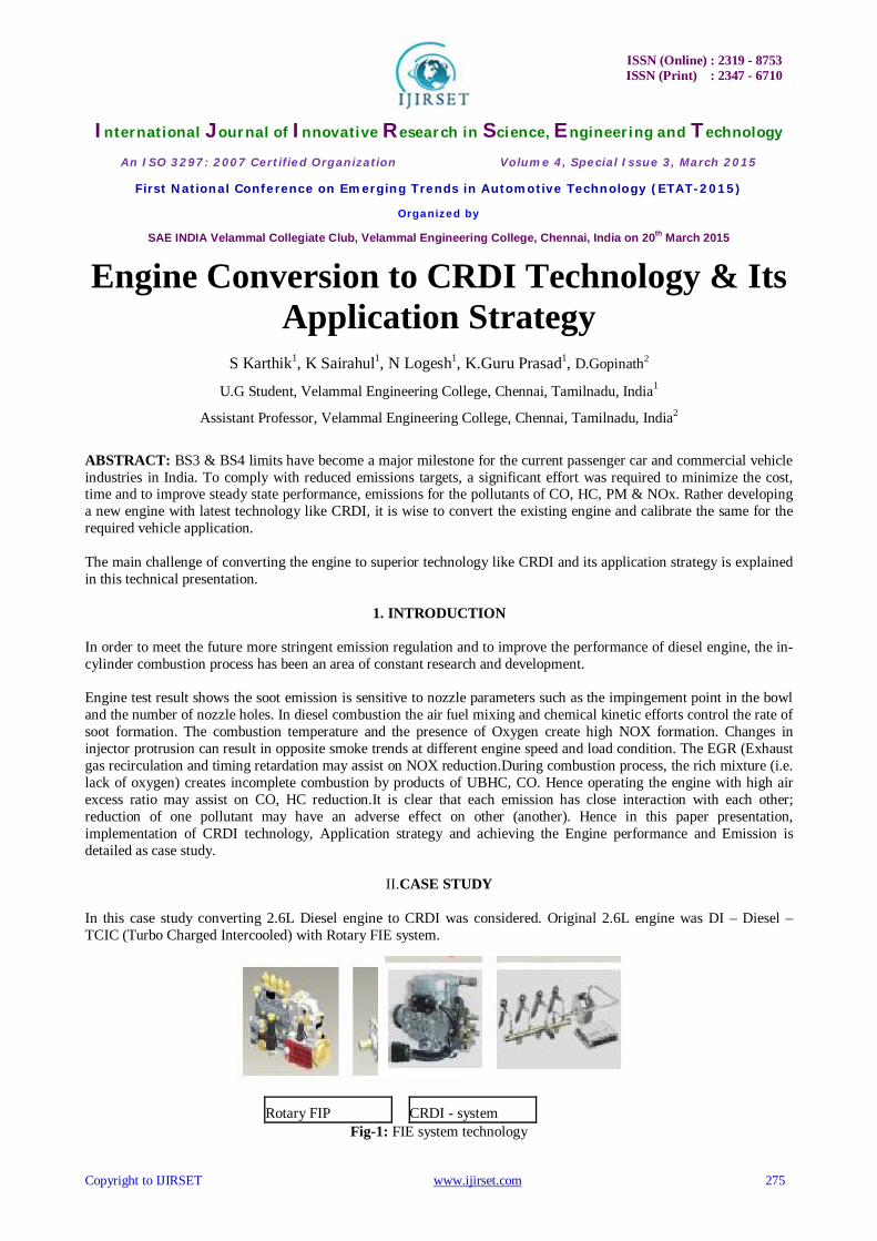
II.CASE STUDY In this case study converting 2.6L Diesel engine to CRDI was considered. Original 2.6L engine was DI – Diesel – TCIC (Turbo Charged Intercooled) with Rotary FIE system.
Rotary FIP CRDI - system Fig-1: FIE system technology

ISSN (Online) : 2319 - 8753 ISSN (Print) : 2347 - 6710
International Journal of Innovative Research in Science, Engineering and Technology
An ISO 3297: 2007 Certified Organization Volume 4, Special Issue 3, March 2015
First National Conference on Emerging Trends in Automotive Technology (ETAT-2015)
Organized by
SAE INDIA Velammal Collegiate Club, Velammal Engineering College, Chennai, India on 20th March 2015
Copyright to IJIRSET www.ijirset.com 276
CRDI system consists of High pressure pump, Common rail, Solenoid / Piezo Injectors, and engine equipped ECU control. The main purpose of this development program was to retain the relatively inexpensive and simple base engine with CRDI set up and waste-gated turbocharger, and achieving the current BS3 emission without after treatment devices and EGR.The presented work will document the development of low cost and high efficient diesel engine which meets BS3 emission.
III. OBJECTIVE The aim and challenge is to identify the Common rail fuel system and ECU suitable for the engine. And calibrate the engine for current BS3 regulation with revised engineering performance targets.
Fig-2: Common rail technology First commitment is to deliver great reliability, durability and cost-effectiveness solutions.
IV. PROCESS OF CONVERSION 3.1 Project need identification First, the engineering specification, vehicle application, targets like performance, emission, BSFC, smoke, noise, etc are frozen. 3.2 Selection of hardware and software Based on target performance and emission requirements available indigenized FIE system was selected and incorporated into the engine. (As shown in Figure - FIE system consists of High pressure pump, Common rail, Injectors). ECU has two different platforms with inbuilt controlling technology. (i.e. EDC16 & EDC17) EDC16 is based on the fuelling control and EDC17 is based on Torque control.

ISSN (Online) : 2319 - 8753 ISSN (Print) : 2347 - 6710
International Journal of Innovative Research in Science, Engineering and Technology
An ISO 3297: 2007 Certified Organization Volume 4, Special Issue 3, March 2015
First National Conference on Emerging Trends in Automotive Technology (ETAT-2015)
Organized by
SAE INDIA Velammal Collegiate Club, Velammal Engineering College, Chennai, India on 20th March 2015
Copyright to IJIRSET www.ijirset.com 277
Fig-3: Common rail system circuit
3.3 Selection of sensors and wiring harness The common rail system consists of ECU, sensors and actuators. Sensor reads the engine signal and passes to the ECU for signal processing. In turn ECU commands the actuator to perform the desired function. Sensors, wiring harness, actuators are selected based on the common rail system guidelines and ECU requirements. 3.4 Engine First firing After successful integration of customised FIE system, ECU, wiring harness and sensors, Synchronization between crank and cam sensor was established. Engine started with base dataset with a2l and hex file.
V. ENGINE CALIBRATION Calibration of engine management systems requires considerable engineering resources during the development of modern engines. Traditional calibration methods use a combination of steady state engine dynamometer and vehicle testing, but pressure to reduce power train development cost and time is driving development of more advanced calibration techniques. In addition, current CRDI engines will feature 6 injections capabilities (i.e.3 pilots, 1 Main, 2 post injections), governor calibration, ET, FMTC, Rail pressure map development etc. This introduces a greater level of system complexity and increases the test requirements to achieve desired injection parameters and engine mapping. Conventional calibration methods rely on dynamometer mapping and transient vehicle testing to arrive at a power train calibration in a manner that is generally considered somewhat of an art. However, as power train complexity is increased, the calibration process, its duration, and its cost; grow exponentially with the number of DOE. Even for relatively simple systems, achievement of optimized calibrations may become impractical to accomplish The objective of the current work is to develop a methodology for simulation-based calibration in an automated software tool

ISSN (Online) : 2319 - 8753 ISSN (Print) : 2347 - 6710
International Journal of Innovative Research in Science, Engineering and Technology
An ISO 3297: 2007 Certified Organization Volume 4, Special Issue 3, March 2015
First National Conference on Emerging Trends in Automotive Technology (ETAT-2015)
Organized by
SAE INDIA Velammal Collegiate Club, Velammal Engineering College, Chennai, India on 20th March 2015
Copyright to IJIRSET www.ijirset.com 278
4.1 Calibration Methodology The overall methodology for traditional testing setup is shown in Figure 4. As a first step, engine dynamometer pretesting is necessary to develop and validate the engine base dataset. Pretesting is a relatively limited exercise but is important to achieve a high fidelity engine model. The engine model is then processed using a linearized values application in the front end module of INCA. INCA is a calibration tool, which is designed to rapidly access, calibrate and store the ECU data and represent in graphical form in MDA.
Fig-4: Engine test set up
Figure 5: INCA SCREEN SHOT

ISSN (Online) : 2319 - 8753 ISSN (Print) : 2347 - 6710
International Journal of Innovative Research in Science, Engineering and Technology
An ISO 3297: 2007 Certified Organization Volume 4, Special Issue 3, March 2015
First National Conference on Emerging Trends in Automotive Technology (ETAT-2015)
Organized by
SAE INDIA Velammal Collegiate Club, Velammal Engineering College, Chennai, India on 20th March 2015
Copyright to IJIRSET www.ijirset.com 279
Figure 6: MDA SCREEN SHOT 4.2 Emission Test cycle The engine is tested on an engine dynamometer over a sequence of steady-state modes as stated in the below figure. The engine must be operated for the prescribed time in each mode, completing engine speed and load changes in the first 20 seconds. The specified speed shall be held to within ±50 rpm and the specified torque shall be held to within ±2% of the maximum torque at the test speed. Emissions are measured during each mode and averaged over the cycle using a set of weighting factors. Particulate matter emissions are sampled on one filter over the 13 modes. The final emission results are expressed in g/kWh.
Figure 7: ESC test cycle
ISSN (Online) : 2319 - 8753 ISSN (Print) : 2347 - 6710
International Journal of Innovative Research in Science, Engineering and Technology
An ISO 3297: 2007 Certified Organization Volume 4, Special Issue 3, March 2015
First National Conference on Emerging Trends in Automotive Technology (ETAT-2015)
Organized by
SAE INDIA Velammal Collegiate Club, Velammal Engineering College, Chennai, India on 20th March 2015
Copyright to IJIRSET www.ijirset.com 280
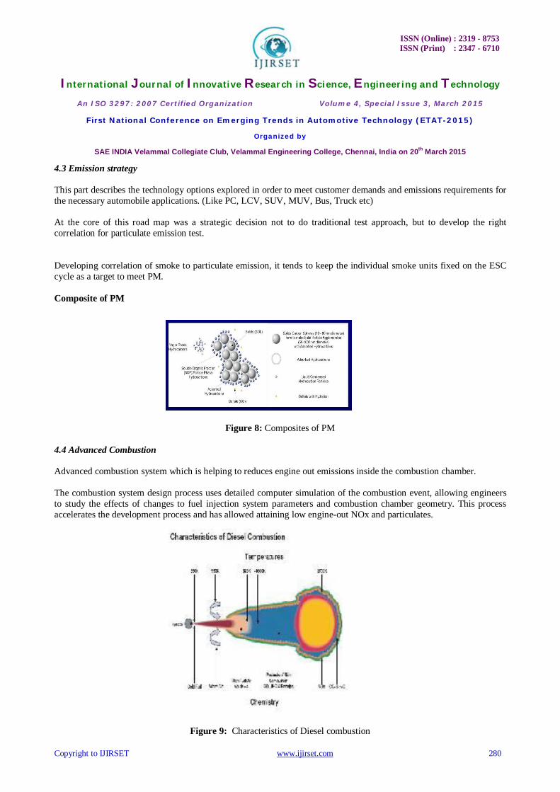
4.3 Emission strategy This part describes the technology options explored in order to meet customer demands and emissions requirements for the necessary automobile applications. (Like PC, LCV, SUV, MUV, Bus, Truck etc) At the core of this road map was a strategic decision not to do traditional test approach, but to develop the right correlation for particulate emission test. Developing correlation of smoke to particulate emission, it tends to keep the individual smoke units fixed on the ESC cycle as a target to meet PM. Composite of PM
Figure 8: Composites of PM 4.4 Advanced Combustion Advanced combustion system which is helping to reduces engine out emissions inside the combustion chamber. The combustion system design process uses detailed computer simulation of the combustion event, allowing engineers to study the effects of changes to fuel injection system parameters and combustion chamber geometry. This process accelerates the development process and has allowed attaining low engine-out NOx and particulates.
Figure 9: Characteristics of Diesel combustion

ISSN (Online) : 2319 - 8753 ISSN (Print) : 2347 - 6710
International Journal of Innovative Research in Science, Engineering and Technology
An ISO 3297: 2007 Certified Organization Volume 4, Special Issue 3, March 2015
First National Conference on Emerging Trends in Automotive Technology (ETAT-2015)
Organized by
SAE INDIA Velammal Collegiate Club, Velammal Engineering College, Chennai, India on 20th March 2015
Copyright to IJIRSET www.ijirset.com 281
All combustion related developments are monitored online through P theta diagram.Fuel injection parameters such as Main injection timing, Pilot injection, Pilot injection separation, Post injection activation strategy, Rail pressure, etc are monitored through INCA. 4.5 Fuel economy benefit The Common rail system uses electronic controlled diesel injection which gets ECU signal for energizing the solenoid for diesel injection. The duration of injection is depends upon the rate of energisation. And during the deceleration, the intelligence of ECU, it cuts off the electrical supply to solenoid injector which in turn contributes to fuel economy improvements. 4.6 BS3 Achievements Advanced combustion system and engineering approach on calibration brought BS3 success in first phase. The easy achievement of BS3 is due to High pressure injection and Pilot and Main injection strategies. Advantages of Pilot injection will help on premixing of air and fuel mixture and makes it ready for ease of combustion; it reduces the ignition delay, Sudden Peak Pressure and reduces the knock and noise. The Common Rail Diesel Injection has following flexibility, CRS – Flexible injection system
Fig-10: CRDI – injection technology Selection of pilot injection qty, Preselecting of no of pilots Adjustment of Pilot separation, Main injection quantity Main injection timing Preselecting of different Rail pressure for engine operation Due to these versatile facilities, the engine performance, emission, combustion improves a lot.

ISSN (Online) : 2319 - 8753 ISSN (Print) : 2347 - 6710
International Journal of Innovative Research in Science, Engineering and Technology
An ISO 3297: 2007 Certified Organization Volume 4, Special Issue 3, March 2015
First National Conference on Emerging Trends in Automotive Technology (ETAT-2015)
Organized by
SAE INDIA Velammal Collegiate Club, Velammal Engineering College, Chennai, India on 20th March 2015
Copyright to IJIRSET www.ijirset.com 282
CRDI application steps Selection of required hardware, software Hardware consists of high pressure pump, Common rail, solenoid injectors and ECU. Software consists of A2L, HEX file, Data set. Dataset is inbuilt with maps, curves and other measurement, calibration variables. Engine First firing ECU governor calibration Optimizing the dataset with desired maps on test bed Achieving the desired performance, emission targets Engine certification Engine integration on vehicle Vehicle level calibration. Vehicle dynamics optimisation Engine, vehicle validation for climatic trials Engine, vehicle durability Emission robustness test Dataset freezing Engine / Vehicle SOP. (Start of Production)
ACKNOWLEDGMENT The authors would like to express special thanks to HOD mechanical department and other professors for giving us a chance to present this paper in the technical conference. Glossary CRDI -Common-Rail Diesel Injection
BS3, BS4 - Bharat Stage 3, 4
EGR -Exhaust Gas Recirculation.
BTDC -Before top dead centre

ISSN (Online) : 2319 - 8753 ISSN (Print) : 2347 - 6710
International Journal of Innovative Research in Science, Engineering and Technology
An ISO 3297: 2007 Certified Organization Volume 4, Special Issue 3, March 2015
First National Conference on Emerging Trends in Automotive Technology (ETAT-2015)
Organized by
SAE INDIA Velammal Collegiate Club, Velammal Engineering College, Chennai, India on 20th March 2015
Copyright to IJIRSET www.ijirset.com 283
TDC -Top dead centre
CO -Carbon Monoxide
HC -Unburned hydrocarbon
NOx -Oxides of Nitrogen
PM -Particulate Matter,
VGT -Variable Geometry Turbocharger.
DPF -Diesel Particulate Filter Exhaust After treatment: Any technology which treats emissions in the exhaust flow.
REFERENCES 1. Tow TC, Pierpont DA, Reitz RD. Reducing particulate and NOX emissions by using multiple injections in a heavy duty DI diesel engine. SAE
paper 940897. 2. Improvement of Fuel economy of an IDI engine with two stage injection. By Kouji Iwazaki, Kenji Amagai, Masataka Arai. 3. Internal combustion engine fundamentals by John B Heywood.
Related Documents