Citation: Wang, M.; Hu, E.; Chen, L. Energy-Saving Potential of Thermal Diode Tank Assisted Refrigeration and Air-Conditioning Systems. Energies 2022, 15, 206. https:// doi.org/10.3390/en15010206 Academic Editors: Wei-Hsin Chen, Aristotle T. Ubando, Chih-Che Chueh and Liwen Jin Received: 30 November 2021 Accepted: 28 December 2021 Published: 29 December 2021 Publisher’s Note: MDPI stays neutral with regard to jurisdictional claims in published maps and institutional affil- iations. Copyright: © 2021 by the authors. Licensee MDPI, Basel, Switzerland. This article is an open access article distributed under the terms and conditions of the Creative Commons Attribution (CC BY) license (https:// creativecommons.org/licenses/by/ 4.0/). energies Article Energy-Saving Potential of Thermal Diode Tank Assisted Refrigeration and Air-Conditioning Systems Mingzhen Wang , Eric Hu * and Lei Chen School of Mechanical Engineering, The University of Adelaide, Adelaide, SA 5005, Australia; [email protected] (M.W.); [email protected] (L.C.) * Correspondence: [email protected] Abstract: Lowering the condensing temperature of the Refrigeration and Air-conditioning (RAC) system has been proven to effectively increase the system’s Coefficient of Performance (COP). This paper revolves around evaluating the energy-saving generated by applying a Thermal Diode Tank (TDT) in the RAC systems. The TDT is a novel invention, which is an insulated water tank equipped with gravity heat pipes. If the TDT was placed outdoors overnight, its inside water would theoretically be at the minimum ambient temperature of the previous night. When the TDT water is used to cool the condenser of RAC systems that operate during the daytime, a higher COP of this TDT assisted RAC (TDT-RAC) system could be achieved compared with the baseline system. In this study, a steady-state performance simulation model for TDT-RAC cycles has been developed. The model reveals that the COP of the TDT-RAC cycle can be improved by 10~59% over the baseline cycle depending on the compressor types. The TDT-RAC cycle with a variable speed compressor can save more energy than that with a fixed speed compressor. In addition, TDT-RAC cycles can save more energy with a higher day/night ambient temperature difference. There is a threshold tank size for a given TDT-RAC cycle to save energy, and the energy-saving can be improved by enlarging the tank size. A desk-top case study based on real weather data for Adelaide in January 2021 shows that 9~40% energy could be saved by TDT-RAC systems every summer day on average. Keywords: refrigeration; heat pipe; thermal diode tank; COP improvement; vapor compression cycle; potential energy savings 1. Introduction Conserving energy is a major global challenge, and one of the most effective methods is to find solutions from energy efficiency improvements. Due to the rapid development of the world economy, ever more public buildings have been built, leading to an increasing requirement of heating, ventilation, and air-conditioning (HVAC) [1]. According to the pro- jections of Australian Government 0 s Department of Climate Change and Energy Efficiency in 2012 [2], electricity is the main source of energy for commercial buildings, accounting for about 50% of the above-mentioned total energy consumption, of which HVAC are usually the largest end-users of electricity. In addition, about 20~30% of energy consumption is yielded by the refrigeration and air-conditioning (RAC) system, producing over 34.7 Mt of total carbon emissions [3]. The report ‘State of the Climate 2020: Bureau of Meteorology’ [4] predicted that Australia is facing a trend of continued climate warming. Australia straddles a mainly temperate climate in densely populated coastal areas, which is characterised by large day and night ambient temperature differences in summer [5]. Since the average annual temperature in Australia is relatively high, and the hot period is much longer than the cold period, the demand for cooling is much greater than for heating. Moreover, traditional cooling demand industries such as food and pharmaceutical factories, datacentres, and wine industries, all make growing demands for more refrigeration and air-conditioning [1]. Energies 2022, 15, 206. https://doi.org/10.3390/en15010206 https://www.mdpi.com/journal/energies

Welcome message from author
This document is posted to help you gain knowledge. Please leave a comment to let me know what you think about it! Share it to your friends and learn new things together.
Transcript
�����������������
Citation: Wang, M.; Hu, E.; Chen, L.
Energy-Saving Potential of Thermal
Diode Tank Assisted Refrigeration
and Air-Conditioning Systems.
Energies 2022, 15, 206. https://
doi.org/10.3390/en15010206
Academic Editors: Wei-Hsin Chen,
Aristotle T. Ubando, Chih-Che Chueh
and Liwen Jin
Received: 30 November 2021
Accepted: 28 December 2021
Published: 29 December 2021
Publisher’s Note: MDPI stays neutral
with regard to jurisdictional claims in
published maps and institutional affil-
iations.
Copyright: © 2021 by the authors.
Licensee MDPI, Basel, Switzerland.
This article is an open access article
distributed under the terms and
conditions of the Creative Commons
Attribution (CC BY) license (https://
creativecommons.org/licenses/by/
4.0/).
energies
Article
Energy-Saving Potential of Thermal Diode Tank AssistedRefrigeration and Air-Conditioning SystemsMingzhen Wang , Eric Hu * and Lei Chen
School of Mechanical Engineering, The University of Adelaide, Adelaide, SA 5005, Australia;[email protected] (M.W.); [email protected] (L.C.)* Correspondence: [email protected]
Abstract: Lowering the condensing temperature of the Refrigeration and Air-conditioning (RAC)system has been proven to effectively increase the system’s Coefficient of Performance (COP). Thispaper revolves around evaluating the energy-saving generated by applying a Thermal Diode Tank(TDT) in the RAC systems. The TDT is a novel invention, which is an insulated water tank equippedwith gravity heat pipes. If the TDT was placed outdoors overnight, its inside water would theoreticallybe at the minimum ambient temperature of the previous night. When the TDT water is used to coolthe condenser of RAC systems that operate during the daytime, a higher COP of this TDT assistedRAC (TDT-RAC) system could be achieved compared with the baseline system. In this study, asteady-state performance simulation model for TDT-RAC cycles has been developed. The modelreveals that the COP of the TDT-RAC cycle can be improved by 10~59% over the baseline cycledepending on the compressor types. The TDT-RAC cycle with a variable speed compressor can savemore energy than that with a fixed speed compressor. In addition, TDT-RAC cycles can save moreenergy with a higher day/night ambient temperature difference. There is a threshold tank size fora given TDT-RAC cycle to save energy, and the energy-saving can be improved by enlarging thetank size. A desk-top case study based on real weather data for Adelaide in January 2021 shows that9~40% energy could be saved by TDT-RAC systems every summer day on average.
Keywords: refrigeration; heat pipe; thermal diode tank; COP improvement; vapor compression cycle;potential energy savings
1. Introduction
Conserving energy is a major global challenge, and one of the most effective methodsis to find solutions from energy efficiency improvements. Due to the rapid development ofthe world economy, ever more public buildings have been built, leading to an increasingrequirement of heating, ventilation, and air-conditioning (HVAC) [1]. According to the pro-jections of Australian Government′s Department of Climate Change and Energy Efficiencyin 2012 [2], electricity is the main source of energy for commercial buildings, accounting forabout 50% of the above-mentioned total energy consumption, of which HVAC are usuallythe largest end-users of electricity. In addition, about 20~30% of energy consumption isyielded by the refrigeration and air-conditioning (RAC) system, producing over 34.7 Mt oftotal carbon emissions [3].
The report ‘State of the Climate 2020: Bureau of Meteorology’ [4] predicted thatAustralia is facing a trend of continued climate warming. Australia straddles a mainlytemperate climate in densely populated coastal areas, which is characterised by largeday and night ambient temperature differences in summer [5]. Since the average annualtemperature in Australia is relatively high, and the hot period is much longer than the coldperiod, the demand for cooling is much greater than for heating. Moreover, traditionalcooling demand industries such as food and pharmaceutical factories, datacentres, andwine industries, all make growing demands for more refrigeration and air-conditioning [1].
Energies 2022, 15, 206. https://doi.org/10.3390/en15010206 https://www.mdpi.com/journal/energies

Energies 2022, 15, 206 2 of 16
Consequently, improving the energy efficiency of cooling systems has greater significancethan improving heating systems.
Lowering the condensing temperature of the RAC system has been validated toeffectively increase the system’s Coefficient of Performance (COP). Walsh [6] found thatthe COP for a RAC system normally ranges from 0 to 7 if no condenser cooling measuresare applied. A 1 ◦C decrease in the condensing temperature would result in a 3.23%augmentation in the COP [7]. One of the successful examples of condenser cooling measureis the application of Ground-sourced RAC (GSRAC) systems, as the average undergroundsoil temperature is lower than the ambient temperature during the day time in summer. Atypical GSRAC system can reduce 30~40% energy compared with a normal RAC system(baseline system). However, GSRAC system would occupy considerable land resources todrill and install boreholes, which could be up to 200 m deep, and their payback periods aretoo long, basically over 7 years [8–10].
In addition to GSRAC systems, many other measures have been developed to lowerthe condensing temperature and improve the COP of the RAC system. Zhang et al. [11]examined an integrated RAC system with evaporative air-coolers that cool the air beforeit enters the condenser. The COP of this integrated system shows a 39% increase in theCOP under the hot-arid area of China. Wang et al. [12] also utilised an evaporative coolingcondenser in an existing air-conditioning system, which yielded a COP augmentation by12%. Another experiment conducted by Yu and Chan [13] found that the evaporative coolerscould increase the COP of air-cooled chillers by up to 20%. However, the energy-savingperformance of these evaporative coolers would be reduced with the higher humidity, sotheir applications in most humid regions are limited. Waly et al. [14] also experimentedwith an evaporative cooling method, in which the inlet air was cooled by the sprayingwater before entering the condenser, and their results indicated an increase in COP by 36%.In this experiment, a problem was faced that the condenser should be placed away fromobstructions because the shading of condenser would reduce the COP.
Chen et al. [15] assessed the ability of liquid–vapor separation condensers (LSC)and found that the COP of the LSC system was improved by 11.1% compared with thebaseline system. To further improve the LSC system, Zhong et al. [16] studied the impactof a double-row liquid–vapor separation condenser (DLSC) on the RAC system coolingperformance. This novel condenser achieved an improvement in the COP by about 30%. Inboth researches, the cooling performance of separation condensers is constrained by theambient temperature; if the ambient temperature was over 40 ◦C, these systems wouldeven have lower COPs.
While utilising the mist generator to supply cold mist for the RAC system’s condenser,Yang et al. [17] achieved a considerable COP improvement of 21.3~51.5%, which is higherthan those of most evaporative cooling methods. In application, the mist generator requiresan open-loop water tower that consumes water to produce mist, which would be a wasteof water resource.
Above literatures revealed that the performance enhancement of RAC systems wasachieved using different condenser cooling methods, with significant COP improvements.However, there is little investigation on how to calculate the theoretical value of COP invapor compression refrigeration cycles when the condenser cooling methods are applied.In addition to the defects and deficiencies summarized above, extra energy is also requiredto run the cooling units, such as air-coolers and mist generators.
In this paper, the Thermal Diode Tank (TDT) is a potential cost-effective alternative ofother condenser cooling measures to supply water-cooling for RAC systems. Unlike above-mentioned studies, the TDT works automatically and passively that does not consumeadditional energy or resources. Basically, a TDT is an insulated water tank equipped withgravity heat pipes, which can passively release heat to the ambient air if the ambienttemperature is lower than the water temperature inside TDT, but would not allow the heatto enter the tank even when the ambient temperature is higher. The RAC system equippedwith a TDT is expected to generate a reduction of up to 40% in its energy consumption

Energies 2022, 15, 206 3 of 16
compared with a baseline system in the presence of day and night ambient temperaturedifferences. However, since TDT is a newly invented technology, there has been littlesystematic research into it. Correlations between the design and operation parametersof TDT and its improvement are unknown. The aim of this study is to understand thepotential of TDT when it is used to supply cooling water to a baseline system, by conductingdesk-top case studies.
2. Thermal Diode Tank (TDT)
The TDT was proposed by Hu and Kimenkowski in 2019, which is constructed asa well-insulated water tank equipped with gravity heat pipes. The Gravity Heat Pipe(GHP, shown in Figure 1) is an isolated pipe containing a working fluid that coexists inliquid and vapor states [18]. When the temperature at the evaporator section of the GHPis higher, the working fluid (water, R134a, ammonia, etc.) will evaporate from liquid tovapor phase. The vapor rises upwards where the temperature is lower than that at theevaporator section, and condenses to release heat at the condenser section. After the vaporcondenses, the condensate (liquid working fluid) flows back to the evaporator sectiondue to the gravity [19]. A continuous circulation inside the GHP can be established ifthe evaporator temperature is higher than the condenser temperature. Oppositely, theheat will not be transferred downwards even though the condenser temperature is higherthan the evaporator temperature. Therefore, the GHP functions as a thermal diode andautomatically transfers heat only in one direction, from evaporator to condenser [20]. Thethermal resistance inside a GHP is almost nil, so this device is very efficient in heat transfer.In practice, if the GHP evaporator temperature was higher than its condenser temperatureby 1 ◦C or more, it would start operating.
Energies 2021, 14, x FOR PEER REVIEW 3 of 17
heat to enter the tank even when the ambient temperature is higher. The RAC system equipped with a TDT is expected to generate a reduction of up to 40% in its energy con-sumption compared with a baseline system in the presence of day and night ambient tem-perature differences. However, since TDT is a newly invented technology, there has been little systematic research into it. Correlations between the design and operation parame-ters of TDT and its improvement are unknown. The aim of this study is to understand the potential of TDT when it is used to supply cooling water to a baseline system, by conduct-ing desk-top case studies.
2. Thermal Diode Tank (TDT) The TDT was proposed by Hu and Kimenkowski in 2019, which is constructed as a
well-insulated water tank equipped with gravity heat pipes. The Gravity Heat Pipe (GHP, shown in Figure 1) is an isolated pipe containing a working fluid that coexists in liquid and vapor states [18]. When the temperature at the evaporator section of the GHP is higher, the working fluid (water, R134a, ammonia, etc.) will evaporate from liquid to va-por phase. The vapor rises upwards where the temperature is lower than that at the evap-orator section, and condenses to release heat at the condenser section. After the vapor condenses, the condensate (liquid working fluid) flows back to the evaporator section due to the gravity [19]. A continuous circulation inside the GHP can be established if the evap-orator temperature is higher than the condenser temperature. Oppositely, the heat will not be transferred downwards even though the condenser temperature is higher than the evaporator temperature. Therefore, the GHP functions as a thermal diode and automati-cally transfers heat only in one direction, from evaporator to condenser [20]. The thermal resistance inside a GHP is almost nil, so this device is very efficient in heat transfer. In practice, if the GHP evaporator temperature was higher than its condenser temperature by 1 °C or more, it would start operating.
Figure 1. Gravity heat pipe working diagram.
The conceptual working diagram of the TDT is illustrated in Figure 2. With the one-direction heat transfer capability provided by GHPs, the TDT can release heat to the am-bient air only if its inside water temperature is higher than the ambient temperature, but the heat from outside cannot enter the TDT. The adiabatic section of the GHPs prevents the heat from being transferred from the condenser section to the evaporator section by
Figure 1. Gravity heat pipe working diagram.
The conceptual working diagram of the TDT is illustrated in Figure 2. With the one-direction heat transfer capability provided by GHPs, the TDT can release heat to the ambientair only if its inside water temperature is higher than the ambient temperature, but the heatfrom outside cannot enter the TDT. The adiabatic section of the GHPs prevents the heatfrom being transferred from the condenser section to the evaporator section by conductioneven with scorching ambient temperatures. If such a device was placed outdoors overnight,the TDT water would theoretically be at the minimum ambient temperature of the lastnight. Thus, the TDT can passively harvest cold energy from the day/night ambient

Energies 2022, 15, 206 4 of 16
temperature differences to produce cooling water to lower the condensing temperature ofthe RAC system.
Energies 2021, 14, x FOR PEER REVIEW 4 of 17
conduction even with scorching ambient temperatures. If such a device was placed out-doors overnight, the TDT water would theoretically be at the minimum ambient temper-ature of the last night. Thus, the TDT can passively harvest cold energy from the day/night ambient temperature differences to produce cooling water to lower the condensing tem-perature of the RAC system.
Figure 2. TDT working diagram.
Figure 3 shows the schematic diagram of the proposed TDT-RAC system. When the water at the minimum ambient temperature of the previous night is used to cool the RAC system’s condenser, the COP of this integrated system would increase significantly. Namely, during the day time, the TDT-RAC system virtually works at a minimum ambi-ent temperature of the last night. It is predicted that a lower night ambient temperature and a larger tank size are more beneficial to the TDT-RAC system, since colder and more cooling water can be produced for the RAC system’s condenser.
Figure 3. Schematic diagram of a TDT-RAC system.
Figure 2. TDT working diagram.
Figure 3 shows the schematic diagram of the proposed TDT-RAC system. Whenthe water at the minimum ambient temperature of the previous night is used to cool theRAC system’s condenser, the COP of this integrated system would increase significantly.Namely, during the day time, the TDT-RAC system virtually works at a minimum ambienttemperature of the last night. It is predicted that a lower night ambient temperature and alarger tank size are more beneficial to the TDT-RAC system, since colder and more coolingwater can be produced for the RAC system’s condenser.
Energies 2021, 14, x FOR PEER REVIEW 4 of 17
conduction even with scorching ambient temperatures. If such a device was placed out-doors overnight, the TDT water would theoretically be at the minimum ambient temper-ature of the last night. Thus, the TDT can passively harvest cold energy from the day/night ambient temperature differences to produce cooling water to lower the condensing tem-perature of the RAC system.
Figure 2. TDT working diagram.
Figure 3 shows the schematic diagram of the proposed TDT-RAC system. When the water at the minimum ambient temperature of the previous night is used to cool the RAC system’s condenser, the COP of this integrated system would increase significantly. Namely, during the day time, the TDT-RAC system virtually works at a minimum ambi-ent temperature of the last night. It is predicted that a lower night ambient temperature and a larger tank size are more beneficial to the TDT-RAC system, since colder and more cooling water can be produced for the RAC system’s condenser.
Figure 3. Schematic diagram of a TDT-RAC system.
Figure 3. Schematic diagram of a TDT-RAC system.
3. Modelling of TDT-RAC Cycles
To evaluate the energy-saving performance of TDT-RAC systems compared withthe baseline system, steady-state performance simulation models for TDT-RAC cycleswere developed.

Energies 2022, 15, 206 5 of 16
3.1. Baseline Cycle
The cycle COP of a vapour compression RAC system in Figure 4 can be expressed interms of enthalpies [21]:
COPcycle 1 =
.QRAC
.WC
=h1 − h4
h2 − h1(1)
where .QRAC =
.m1(h1 − h4) (2)
.WC =
.m1(h2 − h1) (3)
and.
m1 (kg/s) is the refrigerant mass flow rate of the baseline cycle (Cycle 1), and h (kJ/kg)represents the specific enthalpy.
Energies 2021, 14, x FOR PEER REVIEW 5 of 17
3. Modelling of TDT-RAC Cycles To evaluate the energy-saving performance of TDT-RAC systems compared with the
baseline system, steady-state performance simulation models for TDT-RAC cycles were developed.
3.1. Baseline Cycle The cycle COP of a vapour compression RAC system in Figure 4 can be expressed in
terms of enthalpies [21]: 𝐶𝑂𝑃 = 𝑄𝑊 = ℎ − ℎ ℎ − ℎ (1)
where 𝑄 = 𝑚 (ℎ − ℎ ) (2) 𝑊 = 𝑚 (ℎ − ℎ ) (3)
and 𝑚 (kg/s) is the refrigerant mass flow rate of the baseline cycle (Cycle 1), and h (kJ/kg) represents the specific enthalpy.
(a) (b)
Figure 4. (a) Vapor compression RAC system; (b) Baseline cycle (Cycle 1) in T-s diagram (1→2→3→4→1).
From Equation (1), it is observed that the COP can be improved theoretically by either increasing the enthalpy gap between h1 and h4, and/or decreasing the enthalpy gap be-tween h2 and h1. It is noted that h1 depends on the required evaporating temperature (T1), which it is unable to vary, otherwise the cooling demand cannot be met. Therefore, in engineering practice, h4 and/or h2 are lowered to improve the COP of the RAC system. From state 3 to 4, the refrigerant passes the expansion valve where there is no energy transfer, so the enthalpy during this process is constant (h3 = h4). Therefore, h4 and h2 both depend on the condensing temperature (T3), and an improvement in COP can be achieved by lowering the condensing temperature of the RAC system.
3.2. TDT-RAC Cycles Depending on the compressor type (i.e., fixed speed or variable speed) of RAC sys-
tems, the impacts of the TDT on the RAC cycle are different. A fixed speed compressor
Figure 4. (a) Vapor compression RAC system; (b) Baseline cycle (Cycle 1) in T-s diagram(1→2→3→4→1).
From Equation (1), it is observed that the COP can be improved theoretically byeither increasing the enthalpy gap between h1 and h4, and/or decreasing the enthalpy gapbetween h2 and h1. It is noted that h1 depends on the required evaporating temperature(T1), which it is unable to vary, otherwise the cooling demand cannot be met. Therefore,in engineering practice, h4 and/or h2 are lowered to improve the COP of the RAC system.From state 3 to 4, the refrigerant passes the expansion valve where there is no energytransfer, so the enthalpy during this process is constant (h3 = h4). Therefore, h4 and h2 bothdepend on the condensing temperature (T3), and an improvement in COP can be achievedby lowering the condensing temperature of the RAC system.
3.2. TDT-RAC Cycles
Depending on the compressor type (i.e., fixed speed or variable speed) of RAC systems,the impacts of the TDT on the RAC cycle are different. A fixed speed compressor alwaysruns at a full capacity, while a variable speed compressor virtually runs at 25% to 100%capacity [22]. Figure 5 illustrates the differences in cycles in T-s diagrams with differentcompressors when the condensing temperature decreases. Figure 5a shows the TDT-RAC cycle with a fixed speed compressor (Cycle 2), in which the cycle 1→2→3→4→1represents the baseline cycle, and Figure 5b shows the TDT-RAC cycle with a variablespeed compressor (Cycle 3):
Energies 2022, 15, 206 6 of 16
Energies 2021, 14, x FOR PEER REVIEW 6 of 17
always runs at a full capacity, while a variable speed compressor virtually runs at 25% to 100% capacity [22]. Figure 5 illustrates the differences in cycles in T-s diagrams with dif-ferent compressors when the condensing temperature decreases. Figure 5a shows the TDT-RAC cycle with a fixed speed compressor (Cycle 2), in which the cycle 1→2→3→4→1 represents the baseline cycle, and Figure 5b shows the TDT-RAC cycle with a variable speed compressor (Cycle 3):
(a) (b)
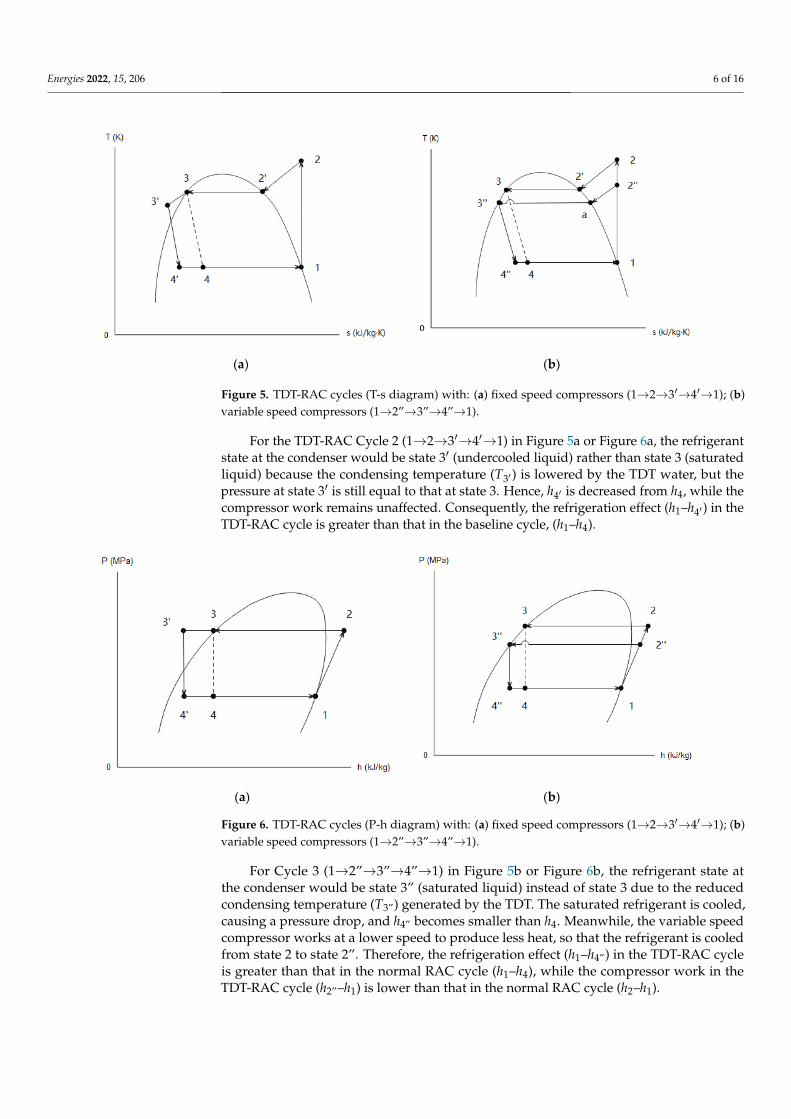
Figure 5. TDT-RAC cycles (T-s diagram) with: (a) fixed speed compressors (1→2→3′→4′→1); (b) variable speed compres-sors (1→2″→3″→4″→1).
For the TDT-RAC Cycle 2 (1→2→3′→4′→1) in Figure 5a or Figure 6a, the refrigerant state at the condenser would be state 3′ (undercooled liquid) rather than state 3 (saturated liquid) because the condensing temperature (T3′) is lowered by the TDT water, but the pressure at state 3′ is still equal to that at state 3. Hence, h4′ is decreased from h4, while the compressor work remains unaffected. Consequently, the refrigeration effect (h1–h4′) in the TDT-RAC cycle is greater than that in the baseline cycle, (h1–h4).
(a) (b)
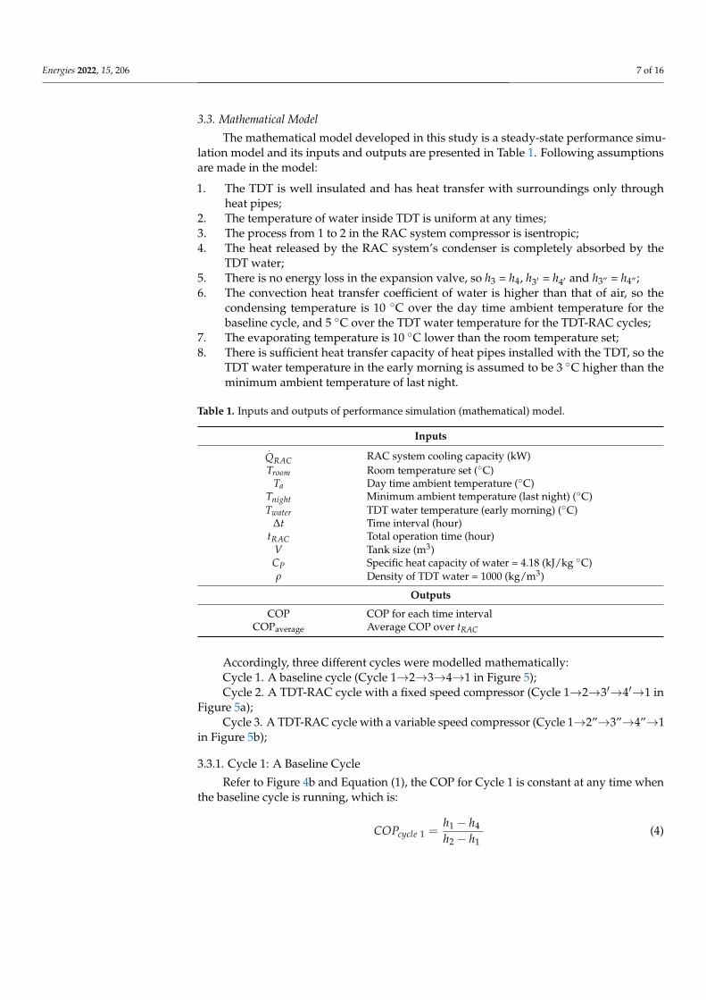
Figure 6. TDT-RAC cycles (P-h diagram) with: (a) fixed speed compressors (1→2→3′→4′→1); (b) variable speed compres-sors (1→2″→3″→4″→1).
Figure 5. TDT-RAC cycles (T-s diagram) with: (a) fixed speed compressors (1→2→3′→4′→1); (b)variable speed compressors (1→2”→3”→4”→1).
For the TDT-RAC Cycle 2 (1→2→3′→4′→1) in Figure 5a or Figure 6a, the refrigerantstate at the condenser would be state 3′ (undercooled liquid) rather than state 3 (saturatedliquid) because the condensing temperature (T3′ ) is lowered by the TDT water, but thepressure at state 3′ is still equal to that at state 3. Hence, h4′ is decreased from h4, while thecompressor work remains unaffected. Consequently, the refrigeration effect (h1–h4′ ) in theTDT-RAC cycle is greater than that in the baseline cycle, (h1–h4).
Energies 2021, 14, x FOR PEER REVIEW 6 of 17
always runs at a full capacity, while a variable speed compressor virtually runs at 25% to 100% capacity [22]. Figure 5 illustrates the differences in cycles in T-s diagrams with dif-ferent compressors when the condensing temperature decreases. Figure 5a shows the TDT-RAC cycle with a fixed speed compressor (Cycle 2), in which the cycle 1→2→3→4→1 represents the baseline cycle, and Figure 5b shows the TDT-RAC cycle with a variable speed compressor (Cycle 3):
(a) (b)
Figure 5. TDT-RAC cycles (T-s diagram) with: (a) fixed speed compressors (1→2→3′→4′→1); (b) variable speed compres-sors (1→2″→3″→4″→1).
For the TDT-RAC Cycle 2 (1→2→3′→4′→1) in Figure 5a or Figure 6a, the refrigerant state at the condenser would be state 3′ (undercooled liquid) rather than state 3 (saturated liquid) because the condensing temperature (T3′) is lowered by the TDT water, but the pressure at state 3′ is still equal to that at state 3. Hence, h4′ is decreased from h4, while the compressor work remains unaffected. Consequently, the refrigeration effect (h1–h4′) in the TDT-RAC cycle is greater than that in the baseline cycle, (h1–h4).
(a) (b)
Figure 6. TDT-RAC cycles (P-h diagram) with: (a) fixed speed compressors (1→2→3′→4′→1); (b) variable speed compres-sors (1→2″→3″→4″→1).
Figure 6. TDT-RAC cycles (P-h diagram) with: (a) fixed speed compressors (1→2→3′→4′→1); (b)variable speed compressors (1→2”→3”→4”→1).
For Cycle 3 (1→2”→3”→4”→1) in Figure 5b or Figure 6b, the refrigerant state atthe condenser would be state 3” (saturated liquid) instead of state 3 due to the reducedcondensing temperature (T3”) generated by the TDT. The saturated refrigerant is cooled,causing a pressure drop, and h4” becomes smaller than h4. Meanwhile, the variable speedcompressor works at a lower speed to produce less heat, so that the refrigerant is cooledfrom state 2 to state 2”. Therefore, the refrigeration effect (h1–h4”) in the TDT-RAC cycleis greater than that in the normal RAC cycle (h1–h4), while the compressor work in theTDT-RAC cycle (h2”–h1) is lower than that in the normal RAC cycle (h2–h1).
Energies 2022, 15, 206 7 of 16
3.3. Mathematical Model
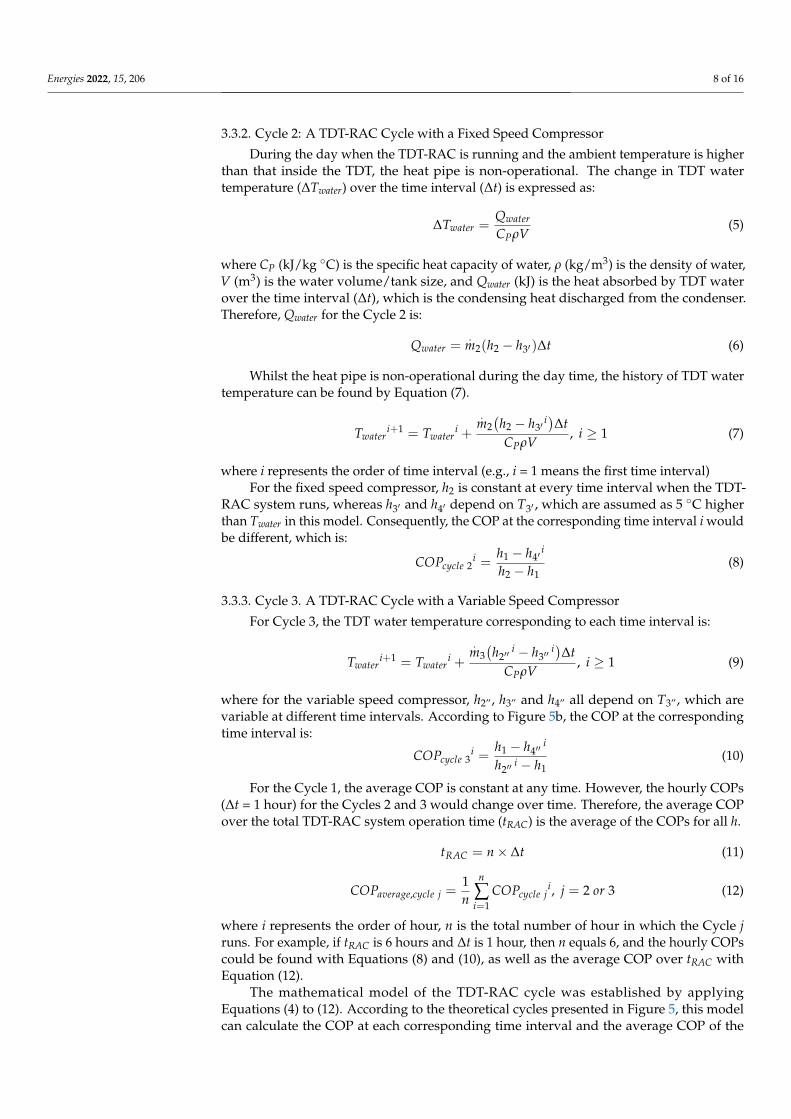
The mathematical model developed in this study is a steady-state performance simu-lation model and its inputs and outputs are presented in Table 1. Following assumptionsare made in the model:
1. The TDT is well insulated and has heat transfer with surroundings only throughheat pipes;
2. The temperature of water inside TDT is uniform at any times;3. The process from 1 to 2 in the RAC system compressor is isentropic;4. The heat released by the RAC system’s condenser is completely absorbed by the
TDT water;5. There is no energy loss in the expansion valve, so h3 = h4, h3′ = h4′ and h3” = h4”;6. The convection heat transfer coefficient of water is higher than that of air, so the
condensing temperature is 10 ◦C over the day time ambient temperature for thebaseline cycle, and 5 ◦C over the TDT water temperature for the TDT-RAC cycles;
7. The evaporating temperature is 10 ◦C lower than the room temperature set;8. There is sufficient heat transfer capacity of heat pipes installed with the TDT, so the
TDT water temperature in the early morning is assumed to be 3 ◦C higher than theminimum ambient temperature of last night.
Table 1. Inputs and outputs of performance simulation (mathematical) model.
Inputs.
QRAC RAC system cooling capacity (kW)Troom Room temperature set (◦C)
Ta Day time ambient temperature (◦C)Tnight Minimum ambient temperature (last night) (◦C)Twater TDT water temperature (early morning) (◦C)
∆t Time interval (hour)tRAC Total operation time (hour)
V Tank size (m3)CP Specific heat capacity of water = 4.18 (kJ/kg ◦C)ρ Density of TDT water = 1000 (kg/m3)
Outputs
COP COP for each time intervalCOPaverage Average COP over tRAC
Accordingly, three different cycles were modelled mathematically:Cycle 1. A baseline cycle (Cycle 1→2→3→4→1 in Figure 5);Cycle 2. A TDT-RAC cycle with a fixed speed compressor (Cycle 1→2→3′→4′→1 in
Figure 5a);Cycle 3. A TDT-RAC cycle with a variable speed compressor (Cycle 1→2”→3”→4”→1
in Figure 5b);
3.3.1. Cycle 1: A Baseline Cycle
Refer to Figure 4b and Equation (1), the COP for Cycle 1 is constant at any time whenthe baseline cycle is running, which is:
COPcycle 1 =h1 − h4
h2 − h1(4)
Energies 2022, 15, 206 8 of 16
3.3.2. Cycle 2: A TDT-RAC Cycle with a Fixed Speed Compressor
During the day when the TDT-RAC is running and the ambient temperature is higherthan that inside the TDT, the heat pipe is non-operational. The change in TDT watertemperature (∆Twater) over the time interval (∆t) is expressed as:
∆Twater =Qwater
CPρV(5)
where CP (kJ/kg ◦C) is the specific heat capacity of water, ρ (kg/m3) is the density of water,V (m3) is the water volume/tank size, and Qwater (kJ) is the heat absorbed by TDT waterover the time interval (∆t), which is the condensing heat discharged from the condenser.Therefore, Qwater for the Cycle 2 is:
Qwater =.
m2(h2 − h3′)∆t (6)
Whilst the heat pipe is non-operational during the day time, the history of TDT watertemperature can be found by Equation (7).
Twateri+1 = Twater
i +
.m2
(h2 − h3′
i)∆tCPρV
, i ≥ 1 (7)
where i represents the order of time interval (e.g., i = 1 means the first time interval)For the fixed speed compressor, h2 is constant at every time interval when the TDT-
RAC system runs, whereas h3′ and h4′ depend on T3′ , which are assumed as 5 ◦C higherthan Twater in this model. Consequently, the COP at the corresponding time interval i wouldbe different, which is:
COPcycle 2i =
h1 − h4′i
h2 − h1(8)
3.3.3. Cycle 3. A TDT-RAC Cycle with a Variable Speed Compressor
For Cycle 3, the TDT water temperature corresponding to each time interval is:
Twateri+1 = Twater
i +
.m3
(h2′′
i − h3′′i)∆t
CPρV, i ≥ 1 (9)
where for the variable speed compressor, h2”, h3” and h4” all depend on T3”, which arevariable at different time intervals. According to Figure 5b, the COP at the correspondingtime interval is:
COPcycle 3i =
h1 − h4′′i
h2′′i − h1
(10)
For the Cycle 1, the average COP is constant at any time. However, the hourly COPs(∆t = 1 hour) for the Cycles 2 and 3 would change over time. Therefore, the average COPover the total TDT-RAC system operation time (tRAC) is the average of the COPs for all h.
tRAC = n× ∆t (11)
COPaverage,cycle j =1n
n
∑i=1
COPcycle ji, j = 2 or 3 (12)
where i represents the order of hour, n is the total number of hour in which the Cycle jruns. For example, if tRAC is 6 hours and ∆t is 1 hour, then n equals 6, and the hourly COPscould be found with Equations (8) and (10), as well as the average COP over tRAC withEquation (12).
The mathematical model of the TDT-RAC cycle was established by applyingEquations (4) to (12). According to the theoretical cycles presented in Figure 5, this modelcan calculate the COP at each corresponding time interval and the average COP of the
Energies 2022, 15, 206 9 of 16
TDT-RAC cycle if all required inputs listed in Table 1 are known. As the aim of this study isto compare the energy consumption and/or COP values of three cycles, and the equationsused in this model are all well-established traditional energy conservation equations, itis considered that the performance simulation model can be verified although it is notexperimentally validated again in this study.
4. Energy-Saving of TDT-RAC Systems4.1. Energy-Saving Indicator
To compare the energy-saving performance of TDT-RAC systems, the energy-savingpercentage (ESP) is defined for both Cycles 2 and 3. For TDT-RAC cycles with a givencooling capacity, the hourly ESP at each time interval (∆t = 1 hour) is calculated as the ratioof saved power consumption of the given TDT-RAC cycle to the power consumption of theCycle 1:
ESPhourly, cycle ji =
.WC,cycle 1 −
.WC,cycle j
i
.WC,cycle j
i× 100%, j = 2 or 3 (13)
where.
WC,cycle ji =
.QRAC
COPcycle ji (14)
It is noted that the cooling capacity (.
QRAC ) of three cycles are the same. Fromdefinition, the hourly ESP can be expressed in terms of enthalpies:
ESPhourly, cycle 2i = 1− h1 − h4
h1 − h4′i (15)
ESPhourly, cycle 3i = 1−
(h1 − h4)(h2′′
i − h1)
(h1 − h4′′i)(h2 − h1)
(16)
The average ESP over the total operation time (tRAC in Equation (11)) is the sum ofeach hourly ESP divided by the total operation time in h.
ESPaverage,cycle j =1n
n
∑i=1
ESPhourly, cycle ji, j = 2 or 3 (17)
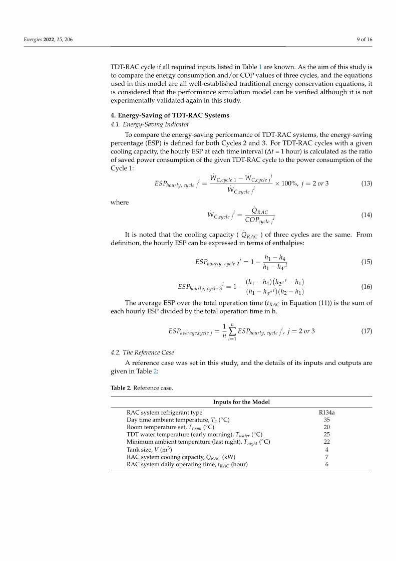
4.2. The Reference Case
A reference case was set in this study, and the details of its inputs and outputs aregiven in Table 2:
Table 2. Reference case.
Inputs for the Model
RAC system refrigerant type R134aDay time ambient temperature, Ta (◦C) 35Room temperature set, Troom (◦C) 20TDT water temperature (early morning), Twater (◦C) 25Minimum ambient temperature (last night), Tnight (◦C) 22Tank size, V (m3) 4RAC system cooling capacity, QRAC (kW) 7RAC system daily operating time, tRAC (hour) 6
Energies 2022, 15, 206 10 of 16
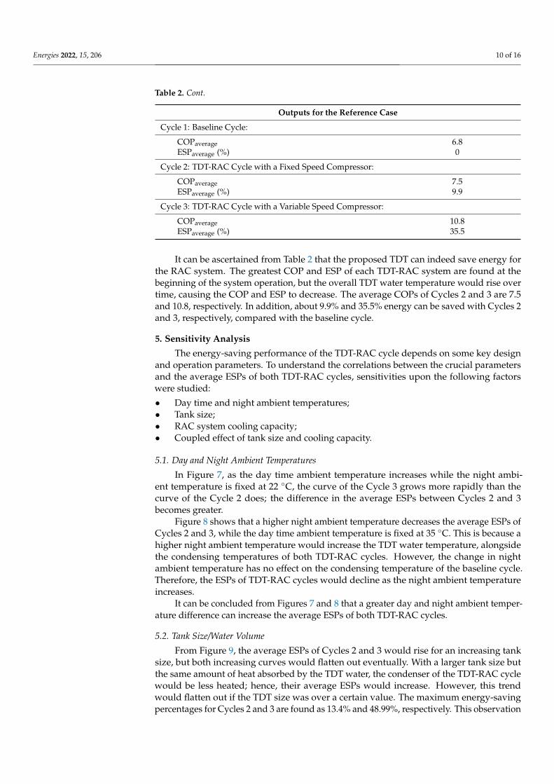
Table 2. Cont.
Outputs for the Reference Case
Cycle 1: Baseline Cycle:
COPaverage 6.8ESPaverage (%) 0
Cycle 2: TDT-RAC Cycle with a Fixed Speed Compressor:
COPaverage 7.5ESPaverage (%) 9.9
Cycle 3: TDT-RAC Cycle with a Variable Speed Compressor:
COPaverage 10.8ESPaverage (%) 35.5
It can be ascertained from Table 2 that the proposed TDT can indeed save energy forthe RAC system. The greatest COP and ESP of each TDT-RAC system are found at thebeginning of the system operation, but the overall TDT water temperature would rise overtime, causing the COP and ESP to decrease. The average COPs of Cycles 2 and 3 are 7.5and 10.8, respectively. In addition, about 9.9% and 35.5% energy can be saved with Cycles 2and 3, respectively, compared with the baseline cycle.
5. Sensitivity Analysis
The energy-saving performance of the TDT-RAC cycle depends on some key designand operation parameters. To understand the correlations between the crucial parametersand the average ESPs of both TDT-RAC cycles, sensitivities upon the following factorswere studied:
• Day time and night ambient temperatures;• Tank size;• RAC system cooling capacity;• Coupled effect of tank size and cooling capacity.
5.1. Day and Night Ambient Temperatures
In Figure 7, as the day time ambient temperature increases while the night ambi-ent temperature is fixed at 22 ◦C, the curve of the Cycle 3 grows more rapidly than thecurve of the Cycle 2 does; the difference in the average ESPs between Cycles 2 and 3becomes greater.
Figure 8 shows that a higher night ambient temperature decreases the average ESPs ofCycles 2 and 3, while the day time ambient temperature is fixed at 35 ◦C. This is because ahigher night ambient temperature would increase the TDT water temperature, alongsidethe condensing temperatures of both TDT-RAC cycles. However, the change in nightambient temperature has no effect on the condensing temperature of the baseline cycle.Therefore, the ESPs of TDT-RAC cycles would decline as the night ambient temperatureincreases.
It can be concluded from Figures 7 and 8 that a greater day and night ambient temper-ature difference can increase the average ESPs of both TDT-RAC cycles.
5.2. Tank Size/Water Volume
From Figure 9, the average ESPs of Cycles 2 and 3 would rise for an increasing tanksize, but both increasing curves would flatten out eventually. With a larger tank size butthe same amount of heat absorbed by the TDT water, the condenser of the TDT-RAC cyclewould be less heated; hence, their average ESPs would increase. However, this trendwould flatten out if the TDT size was over a certain value. The maximum energy-savingpercentages for Cycles 2 and 3 are found as 13.4% and 48.99%, respectively. This observation

Energies 2022, 15, 206 11 of 16
implies that the cost-effectiveness should be considered when determining the TDT size fora given TDT-RAC system.
Energies 2021, 14, x FOR PEER REVIEW 11 of 17
Figure 7. Average ESP versus day time ambient temperature (the minimum night ambient temper-ature is set as 22 °C).
Figure 8 shows that a higher night ambient temperature decreases the average ESPs of Cycles 2 and 3, while the day time ambient temperature is fixed at 35 °C. This is because a higher night ambient temperature would increase the TDT water temperature, alongside the condensing temperatures of both TDT-RAC cycles. However, the change in night am-bient temperature has no effect on the condensing temperature of the baseline cycle. Therefore, the ESPs of TDT-RAC cycles would decline as the night ambient temperature increases.
Figure 8. Average ESP versus night ambient temperature (the day time ambient temperature is set as 35 °C).
It can be concluded from Figures 7 and 8 that a greater day and night ambient tem-perature difference can increase the average ESPs of both TDT-RAC cycles.
Figure 7. Average ESP versus day time ambient temperature (the minimum night ambient tempera-ture is set as 22 ◦C).
Energies 2021, 14, x FOR PEER REVIEW 11 of 17
Figure 7. Average ESP versus day time ambient temperature (the minimum night ambient temper-ature is set as 22 °C).
Figure 8 shows that a higher night ambient temperature decreases the average ESPs of Cycles 2 and 3, while the day time ambient temperature is fixed at 35 °C. This is because a higher night ambient temperature would increase the TDT water temperature, alongside the condensing temperatures of both TDT-RAC cycles. However, the change in night am-bient temperature has no effect on the condensing temperature of the baseline cycle. Therefore, the ESPs of TDT-RAC cycles would decline as the night ambient temperature increases.
Figure 8. Average ESP versus night ambient temperature (the day time ambient temperature is set as 35 °C).
It can be concluded from Figures 7 and 8 that a greater day and night ambient tem-perature difference can increase the average ESPs of both TDT-RAC cycles.
Figure 8. Average ESP versus night ambient temperature (the day time ambient temperature is set as35 ◦C).
In addition, the tank size has a greater impact on the average ESP of the Cycle 3compared with the Cycle 2. This is because a lower condensing temperature can decreasethe input energy of the variable speed compressor, but not for the fixed speed compressor.Therefore, the ESP of the Cycle 3 would be more sensitive to the tank size compared withthe Cycle 2.
It is also ascertained that there is a threshold tank size existing for each TDT-RACcycle to achieve energy-saving. If the tank size is below this threshold, the ESP would benegative, which indicates that the TDT-RAC cycle would consume more energy comparedwith the baseline cycle. In this study case, the threshold tank size to achieve energy-savingfor Cycles 2 and 3 is around 1.22 m3. Finally, the threshold tank sizes for Cycles 2 and 3 areequal. Without other parameter changes, only when the condensing temperatures of both

Energies 2022, 15, 206 12 of 16
TDT-RAC cycles are equal to that of a normal RAC cycle, their ESPs should be zero. In thiscase, their TDT sizes would be the same.
Energies 2021, 14, x FOR PEER REVIEW 12 of 17
5.2. Tank Size/Water Volume From Figure 9, the average ESPs of Cycles 2 and 3 would rise for an increasing tank
size, but both increasing curves would flatten out eventually. With a larger tank size but the same amount of heat absorbed by the TDT water, the condenser of the TDT-RAC cycle would be less heated; hence, their average ESPs would increase. However, this trend would flatten out if the TDT size was over a certain value. The maximum energy-saving percentages for Cycles 2 and 3 are found as 13.4% and 48.99%, respectively. This observa-tion implies that the cost-effectiveness should be considered when determining the TDT size for a given TDT-RAC system.
Figure 9. Average ESP versus day time ambient temperature (the threshold of both TDT-RAC curves is the same, which is about 1.22 m3).
In addition, the tank size has a greater impact on the average ESP of the Cycle 3 com-pared with the Cycle 2. This is because a lower condensing temperature can decrease the input energy of the variable speed compressor, but not for the fixed speed compressor. Therefore, the ESP of the Cycle 3 would be more sensitive to the tank size compared with the Cycle 2.
It is also ascertained that there is a threshold tank size existing for each TDT-RAC cycle to achieve energy-saving. If the tank size is below this threshold, the ESP would be negative, which indicates that the TDT-RAC cycle would consume more energy compared with the baseline cycle. In this study case, the threshold tank size to achieve energy-saving for Cycles 2 and 3 is around 1.22 m3. Finally, the threshold tank sizes for Cycles 2 and 3 are equal. Without other parameter changes, only when the condensing temperatures of both TDT-RAC cycles are equal to that of a normal RAC cycle, their ESPs should be zero. In this case, their TDT sizes would be the same.
5.3. RAC System Cooling Capacity The cooling load is defined as the power required to cool the room at a desirable
temperature, which equals the RAC system cooling capacity. In Figure 10, when the cool-ing capacity (load) increases, the average ESPs of TDT-RAC cycles would decrease. The heat released by the condenser would increase as the cooling capacity increases, alongside the condensing temperatures of Cycles 2 and 3. Therefore, if the tank size remains un-changed while the condensing temperatures increase, Cycles 2 and 3 would have lower ESPs. This finding implies that for a RAC system with a greater cooling demand would require a larger TDT size, in order to satisfy the required energy-saving percentages.
Figure 9. Average ESP versus day time ambient temperature (the threshold of both TDT-RAC curvesis the same, which is about 1.22 m3).
5.3. RAC System Cooling Capacity
The cooling load is defined as the power required to cool the room at a desirabletemperature, which equals the RAC system cooling capacity. In Figure 10, when the coolingcapacity (load) increases, the average ESPs of TDT-RAC cycles would decrease. The heatreleased by the condenser would increase as the cooling capacity increases, alongside thecondensing temperatures of Cycles 2 and 3. Therefore, if the tank size remains unchangedwhile the condensing temperatures increase, Cycles 2 and 3 would have lower ESPs. Thisfinding implies that for a RAC system with a greater cooling demand would require alarger TDT size, in order to satisfy the required energy-saving percentages.
Energies 2021, 14, x FOR PEER REVIEW 13 of 17
Figure 10. Average ESP versus RAC system cooling capacity (the tank size is set as 4 m3).
5.4. Coupled Effect of Tank Size and Cooling Capacity To understand the coupled effect of tank size and the RAC system cooling capacity
on the average ESP, the simulations that generate the results in Figures 9 and 10 are com-bined. The combined results are presented in terms of “Tank Size on Cooling Capacity (TS/CC)” versus the average ESPs in Figure 11. It is observed that the ESPs of Cycles 2 and 3 increase with a larger TS/CC value, but the trendlines would flatten out when the TS/CC value is over 1 m3/kW. In addition, there is a threshold for the TS/CC value that complies with the results presented in Figure 11. Namely, only if the TS/CC value is above the threshold of 0.174 m3/kW, the TDT-RAC cycles would have higher COPs and reduced energy consumptions compared with the baseline cycle, under the conditions of this study.
Figure 11. Average ESP versus “Tank Size on Cooling Capacity (TS/CC)” (the threshold of both TDT-RAC cycles is the same, which is about 0.174 m3/kW).
Figure 10. Average ESP versus RAC system cooling capacity (the tank size is set as 4 m3).
5.4. Coupled Effect of Tank Size and Cooling Capacity
To understand the coupled effect of tank size and the RAC system cooling capacity onthe average ESP, the simulations that generate the results in Figures 9 and 10 are combined.
Energies 2022, 15, 206 13 of 16
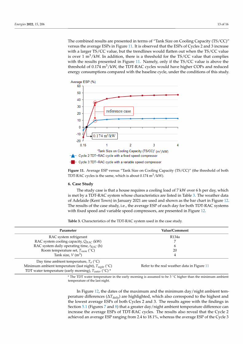
The combined results are presented in terms of “Tank Size on Cooling Capacity (TS/CC)”versus the average ESPs in Figure 11. It is observed that the ESPs of Cycles 2 and 3 increasewith a larger TS/CC value, but the trendlines would flatten out when the TS/CC valueis over 1 m3/kW. In addition, there is a threshold for the TS/CC value that complieswith the results presented in Figure 11. Namely, only if the TS/CC value is above thethreshold of 0.174 m3/kW, the TDT-RAC cycles would have higher COPs and reducedenergy consumptions compared with the baseline cycle, under the conditions of this study.
Energies 2021, 14, x FOR PEER REVIEW 13 of 17
Figure 10. Average ESP versus RAC system cooling capacity (the tank size is set as 4 m3).
5.4. Coupled Effect of Tank Size and Cooling Capacity To understand the coupled effect of tank size and the RAC system cooling capacity
on the average ESP, the simulations that generate the results in Figures 9 and 10 are com-bined. The combined results are presented in terms of “Tank Size on Cooling Capacity (TS/CC)” versus the average ESPs in Figure 11. It is observed that the ESPs of Cycles 2 and 3 increase with a larger TS/CC value, but the trendlines would flatten out when the TS/CC value is over 1 m3/kW. In addition, there is a threshold for the TS/CC value that complies with the results presented in Figure 11. Namely, only if the TS/CC value is above the threshold of 0.174 m3/kW, the TDT-RAC cycles would have higher COPs and reduced energy consumptions compared with the baseline cycle, under the conditions of this study.
Figure 11. Average ESP versus “Tank Size on Cooling Capacity (TS/CC)” (the threshold of both TDT-RAC cycles is the same, which is about 0.174 m3/kW).
Figure 11. Average ESP versus “Tank Size on Cooling Capacity (TS/CC)” (the threshold of bothTDT-RAC cycles is the same, which is about 0.174 m3/kW).
6. Case Study
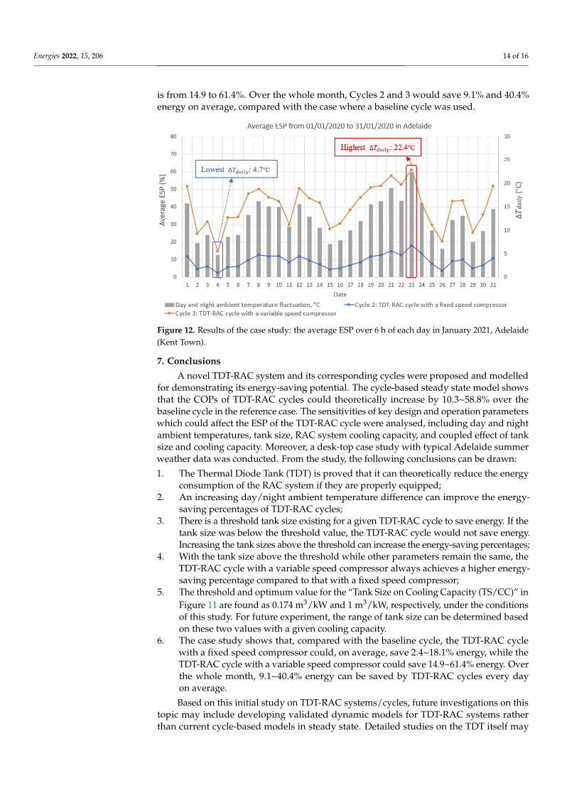
The study case is that a house requires a cooling load of 7 kW over 6 h per day, whichis met by a TDT-RAC system whose characteristics are listed in Table 3. The weather dataof Adelaide (Kent Town) in January 2021 are used and shown as the bar chart in Figure 12.The results of the case study, i.e., the average ESP of each day for both TDT-RAC systemswith fixed speed and variable speed compressors, are presented in Figure 12.
Table 3. Characteristics of the TDT-RAC system used in the case study.
Parameter Value/Comment
RAC system refrigerant R134aRAC system cooling capacity, QRAC (kW) 7
RAC system daily operating time, tRAC (h) 6Room temperature set, Troom (◦C) 20
Tank size, V (m3) 4
Day time ambient temperature, Ta (◦C)Refer to the real weather data in Figure 11Minimum ambient temperature (last night), Tnight (◦C)
TDT water temperature (early morning), Twater (◦C) *
* The TDT water temperature in the early morning is assumed to be 3 ◦C higher than the minimum ambienttemperature of the last night.
In Figure 12, the dates of the maximum and the minimum day/night ambient tem-perature differences (∆Tdaily) are highlighted, which also correspond to the highest andthe lowest average ESPs of both Cycles 2 and 3. The results agree with the findings inSection 5.1 (Figures 7 and 8) that a greater day/night ambient temperature difference canincrease the average ESPs of TDT-RAC cycles. The results also reveal that the Cycle 2achieved an average ESP ranging from 2.4 to 18.1%, whereas the average ESP of the Cycle 3
Energies 2022, 15, 206 14 of 16
is from 14.9 to 61.4%. Over the whole month, Cycles 2 and 3 would save 9.1% and 40.4%energy on average, compared with the case where a baseline cycle was used.
Energies 2021, 14, x FOR PEER REVIEW 14 of 17
6. Case Study The study case is that a house requires a cooling load of 7 kW over 6 h per day, which
is met by a TDT-RAC system whose characteristics are listed in Table 3. The weather data of Adelaide (Kent Town) in January 2021 are used and shown as the bar chart in Figure 12. The results of the case study, i.e., the average ESP of each day for both TDT-RAC sys-tems with fixed speed and variable speed compressors, are presented in Figure 12.
Table 3. Characteristics of the TDT-RAC system used in the case study.
Parameter Value/Comment RAC system refrigerant R134a
RAC system cooling capacity, QRAC (kW) 7 RAC system daily operating time, tRAC (h) 6
Room temperature set, Troom (°C) 20 Tank size, V (m3) 4
Day time ambient temperature, Ta (°C) Refer to the real weather data in Fig-
ure 11 Minimum ambient temperature (last night), Tnight (°C) TDT water temperature (early morning), Twater (°C) *
* The TDT water temperature in the early morning is assumed to be 3 °C higher than the mini-mum ambient temperature of the last night.
Figure 12. Results of the case study: the average ESP over 6 h of each day in January 2021, Adelaide (Kent Town).
In Figure 12, the dates of the maximum and the minimum day/night ambient tem-perature differences (∆Tdaily) are highlighted, which also correspond to the highest and the lowest average ESPs of both Cycles 2 and 3. The results agree with the findings in Section 5.1 (Figures 7 and 8) that a greater day/night ambient temperature difference can increase the average ESPs of TDT-RAC cycles. The results also reveal that the Cycle 2 achieved an average ESP ranging from 2.4 to 18.1%, whereas the average ESP of the Cycle 3 is from 14.9 to 61.4%. Over the whole month, Cycles 2 and 3 would save 9.1% and 40.4% energy on average, compared with the case where a baseline cycle was used.
7. Conclusions A novel TDT-RAC system and its corresponding cycles were proposed and modelled
for demonstrating its energy-saving potential. The cycle-based steady state model shows that the COPs of TDT-RAC cycles could theoretically increase by 10.3~58.8% over the
Figure 12. Results of the case study: the average ESP over 6 h of each day in January 2021, Adelaide(Kent Town).
7. Conclusions
A novel TDT-RAC system and its corresponding cycles were proposed and modelledfor demonstrating its energy-saving potential. The cycle-based steady state model showsthat the COPs of TDT-RAC cycles could theoretically increase by 10.3~58.8% over thebaseline cycle in the reference case. The sensitivities of key design and operation parameterswhich could affect the ESP of the TDT-RAC cycle were analysed, including day and nightambient temperatures, tank size, RAC system cooling capacity, and coupled effect of tanksize and cooling capacity. Moreover, a desk-top case study with typical Adelaide summerweather data was conducted. From the study, the following conclusions can be drawn:
1. The Thermal Diode Tank (TDT) is proved that it can theoretically reduce the energyconsumption of the RAC system if they are properly equipped;
2. An increasing day/night ambient temperature difference can improve the energy-saving percentages of TDT-RAC cycles;
3. There is a threshold tank size existing for a given TDT-RAC cycle to save energy. If thetank size was below the threshold value, the TDT-RAC cycle would not save energy.Increasing the tank sizes above the threshold can increase the energy-saving percentages;
4. With the tank size above the threshold while other parameters remain the same, theTDT-RAC cycle with a variable speed compressor always achieves a higher energy-saving percentage compared to that with a fixed speed compressor;
5. The threshold and optimum value for the “Tank Size on Cooling Capacity (TS/CC)” inFigure 11 are found as 0.174 m3/kW and 1 m3/kW, respectively, under the conditionsof this study. For future experiment, the range of tank size can be determined basedon these two values with a given cooling capacity.
6. The case study shows that, compared with the baseline cycle, the TDT-RAC cyclewith a fixed speed compressor could, on average, save 2.4~18.1% energy, while theTDT-RAC cycle with a variable speed compressor could save 14.9~61.4% energy. Overthe whole month, 9.1~40.4% energy can be saved by TDT-RAC cycles every dayon average.
Based on this initial study on TDT-RAC systems/cycles, future investigations on thistopic may include developing validated dynamic models for TDT-RAC systems ratherthan current cycle-based models in steady state. Detailed studies on the TDT itself may
Energies 2022, 15, 206 15 of 16
include understanding the water temperature profile and thermal stratification inside theTDT under different conditions.
8. Patents
Eric Jing Hu has patent “A HEAT TRANSFER ARRANGEMENT FOR IMPROVEDENERGY EFFICIENCY OF AN AIR CONDITIONING SYSTEM–A thermal ‘Diode Tank’”issued to AU 2014202998 Al.
Author Contributions: Conceptualization, E.H.; methodology, M.W.; software, M.W.; formal analysis,M.W.; investigation, M.W.; resources, M.W.; data curation, M.W. and E.H.; writing—original draftpreparation, M.W.; writing—review and editing, M.W., E.H. and L.C.; supervision, E.H. and L.C.;project administration, E.H. and L.C. All authors have read and agreed to the published version ofthe manuscript.
Funding: This research received no external funding.
Institutional Review Board Statement: Not applicable.
Informed Consent Statement: Not applicable.
Data Availability Statement: The data presented in this study are available on request from thecorresponding author.
Acknowledgments: This research received no external funding. The authors would like to thank theUniversity of Adelaide for providing the University of Adelaide Research Scholarship for this study.
Conflicts of Interest: The authors declare no conflict of interest.
Nomenclature
CP Specific heat capacity (kJ/kg ◦C)Esaved Saved energy (kJ)h Specific enthalpy (kJ/kg).
m Mass flow rate (kg/s)Qout Heat through to condenser(kJ).
Qout The rate of heat through to condenser (kW)QRAC Cooling energy (kJ).
QRAC Cooling capacity (kW)Ta Day time ambient temperature (◦C)Tnight Night time ambient temperature (◦C)Troom Room temperature (◦C)Twater Water temperature (◦C)∆Tdaily Daily day and night ambient temperature difference (◦C)tRAC Refrigeration and air-conditioning system daily operating time (h or s)∆t Refrigeration and air-conditioning system operating time interval (h or s)V Tank size (m3)
.WC Input power by compressor (kW)WC Input energy by compressor (kJ)Greek Symbolsρ Density (kg/m3)AbbreviationsCHP Convective Heat PipeCOP Coefficient of PerformanceEER Energy Efficiency RatioESP Energy-Saving PercentageGHP Gravity Heat PipeGSHP Ground-source Heat PumpHVAC Heating, Ventilation, and Air-conditioningRAC Refrigeration and Air-conditioning

Energies 2022, 15, 206 16 of 16
TDT Thermal Diode TankTDT-RAC Thermal Diode Tank-assisted Refrigeration and Air-conditioning
References1. Sugarman, S.C. HVAC Fundamentals; River Publishers: Gistrup, Denmark, 2020; p. 509.2. Department of Climate Change and Energy Efficiency (DCCEE). Australia’s Emissions Projections, 2012; DCCEE: Canberra,
Australia, 2012.3. Department of Industry, Science, Energy and Resources (DISER). Energy Update: Australian Energy Consumption and Production;
DISER: Canberra, Australia, 2020.4. State of the Climate 2020: Bureau of Meteorology. Available online: http://www.bom.gov.au/state-of-the-climate/ (accessed on
23 September 2021).5. Head, L.; Adams, M.; McGregor, H.V.; Toole, S. Climate change and Australia. Wiley Interdiscip. Rev. Clim. Chang. 2014, 5, 175–197.
[CrossRef]6. Walsh, J.A. Obesity & the First Law of Thermodynamics. Am. Biol. Teach. 2013, 75, 413–415. [CrossRef]7. Kumbhar, A.; Gulhane, N.; Pandure, S. Effect of Various Parameters on Working Condition of Chiller. Energy Procedia 2017, 109,
479–486. [CrossRef]8. Qiao, Z.; Long, T.; Li, W.; Zeng, L.; Li, Y.; Lu, J.; Cheng, Y.; Xie, L.; Yang, L. Performance assessment of ground-source heat pumps
(GSHPs) in the Southwestern and Northwestern China: In situ measurement. Renew. Energy 2020, 153, 214–227. [CrossRef]9. Girard, A.; Gago, E.J.; Muneer, T.; Caceres, G. Higher ground source heat pump COP in a residential building through the use of
solar thermal collectors. Renew. Energy 2015, 80, 26–39. [CrossRef]10. Christodoulides, P.; Aresti, L.; Florides, G. Air-conditioning of a typical house in moderate climates with Ground Source Heat
Pumps and cost comparison with Air Source Heat Pumps. Appl. Therm. Eng. 2019, 158, 113772. [CrossRef]11. HZhang You, S.; Yang, H.; Niu, J. Enhanced performance of air-cooled chillers using evaporative cooling. Build. Serv. Eng. Res.
Technol. 2016, 21, 213–217. [CrossRef]12. Wang, T.; Sheng, C.; Nnanna, A.A. Experimental investigation of air conditioning system using evaporative cooling condenser.
Energy Build. 2014, 81, 435–443. [CrossRef]13. Yu, F.W.; Chan, K.T. Application of Direct Evaporative Coolers for Improving the Energy Efficiency of Air-Cooled Chillers. J. Sol.
Energy Eng. 2005, 127, 430–433. [CrossRef]14. Waly, M.; Chakroun, W.; Al-Mutawa, N.K.; Al-Mutawa, N.K. Effect of pre-cooling of inlet air to condensers of air-conditioning
units. Int. J. Energy Res. 2005, 29, 781–794. [CrossRef]15. Chen, X.; Chen, Y.; Deng, L.; Mo, S.; Zhang, H. Experimental verification of a condenser with liquid–vapor separation in an air
conditioning system. Appl. Therm. Eng. 2013, 51, 48–54. [CrossRef]16. Zhong, T.; Ding, L.; Chen, S.; Chen, Y.; Yang, Q.; Luo, Y. Effect of a double-row liquid–vapor separation condenser on an
air-conditioning unit performance. Appl. Therm. Eng. 2018, 142, 476–482. [CrossRef]17. Yang, J.; Chan, K.; Wu, X.; Yu, F.; Yang, X. An analysis on the energy efficiency of air-cooled chillers with water mist system.
Energy Build. 2012, 55, 273–284. [CrossRef]18. Sözen, A.; Filiz, Ç.; Aytaç, I.; Martin, K.; Ali, H.M.; Boran, K.; Yetisken, Y. Upgrading of the Performance of an Air-to-Air Heat
Exchanger Using Graphene/Water Nanofluid. Int. J. Thermophys. 2021, 42, 35. [CrossRef]19. Dobre, T.; Pârvulescu, O.C.; Stoica, A.; Iavorschi, G. Characterization of cooling systems based on heat pipe principle to control
operation temperature of high-tech electronic components. Appl. Therm. Eng. 2010, 30, 2435–2441. [CrossRef]20. Zohuri, B. Basic Principles of Heat Pipes and History. Heat Pipe Des. Technol. 2016, 3, 1–41. [CrossRef]21. Moran, M.J.; Shapiro, H.N. (Eds.) A Review of: Fundamentals of Engineering Thermodynamics, 2nd ed.; John Wiley & Sons: Chichester,
UK, 1993; Volume 18, p. 215. ISBN 0471592757. [CrossRef]22. Sound Energy: Compressor Speeds and What They Mean. Available online: https://soundenergycorp.com/about-us/blog/
compressor-speeds-and-what-they-mean/ (accessed on 24 November 2021).
Related Documents