Final draft ETSI EN 301 790 V1.4.1 (2005-04) European Standard (Telecommunications series) Digital Video Broadcasting (DVB); Interaction channel for satellite distribution systems European Broadcasting Union Union Européenne de Radio-Télévision EBU·UER

Welcome message from author
This document is posted to help you gain knowledge. Please leave a comment to let me know what you think about it! Share it to your friends and learn new things together.
Transcript

Final draft ETSI EN 301 790 V1.4.1 (2005-04)
European Standard (Telecommunications series)
Digital Video Broadcasting (DVB);Interaction channel for satellite distribution systems
European B roadcasting Union U nion Européenne de R adio-Télévision
EB U·UER

ETSI
Final draft ETSI EN 301 790 V1.4.1 (2005-04) 2
Reference REN/JTC-DVB-169
Keywords broadcasting, DVB, interaction, satellite
ETSI
650 Route des Lucioles F-06921 Sophia Antipolis Cedex - FRANCE
Tel.: +33 4 92 94 42 00 Fax: +33 4 93 65 47 16
Siret N° 348 623 562 00017 - NAF 742 C
Association à but non lucratif enregistrée à la Sous-Préfecture de Grasse (06) N° 7803/88
Important notice
Individual copies of the present document can be downloaded from: http://www.etsi.org
The present document may be made available in more than one electronic version or in print. In any case of existing or perceived difference in contents between such versions, the reference version is the Portable Document Format (PDF).
In case of dispute, the reference shall be the printing on ETSI printers of the PDF version kept on a specific network drive within ETSI Secretariat.
Users of the present document should be aware that the document may be subject to revision or change of status. Information on the current status of this and other ETSI documents is available at
http://portal.etsi.org/tb/status/status.asp
If you find errors in the present document, please send your comment to one of the following services: http://portal.etsi.org/chaircor/ETSI_support.asp
Copyright Notification
No part may be reproduced except as authorized by written permission. The copyright and the foregoing restriction extend to reproduction in all media.
© European Telecommunications Standards Institute 2005.
© European Broadcasting Union 2005. All rights reserved.
DECTTM, PLUGTESTSTM and UMTSTM are Trade Marks of ETSI registered for the benefit of its Members.
TIPHONTM and the TIPHON logo are Trade Marks currently being registered by ETSI for the benefit of its Members. 3GPPTM is a Trade Mark of ETSI registered for the benefit of its Members and of the 3GPP Organizational Partners.

ETSI
Final draft ETSI EN 301 790 V1.4.1 (2005-04) 3
Contents
Intellectual Property Rights ................................................................................................................................7
Foreword.............................................................................................................................................................7
1 Scope ........................................................................................................................................................8
2 References ................................................................................................................................................8
3 Definitions, symbols and abbreviations ...................................................................................................9 3.1 Definitions..........................................................................................................................................................9 3.2 Symbols..............................................................................................................................................................9 3.3 Abbreviations ...................................................................................................................................................10
4 Reference models for satellite interactive networks in DVB .................................................................12 4.1 Protocol stack model ........................................................................................................................................12 4.2 System model ...................................................................................................................................................12 4.3 Reference model of the Satellite Interactive Network......................................................................................13
5 Forward link ...........................................................................................................................................14
6 Return link base-band physical layer specification and multiple access definition ...............................15 6.1 RCST synchronization .....................................................................................................................................15 6.1.1 Timing control ............................................................................................................................................15 6.1.2 Carrier synchronization...............................................................................................................................16 6.1.3 Burst synchronization .................................................................................................................................16 6.1.4 Symbol clock synchronization....................................................................................................................17 6.2 Burst format......................................................................................................................................................17 6.2.1 Traffic (TRF) burst formats ........................................................................................................................17 6.2.1.1 ATM TRF burst ....................................................................................................................................17 6.2.1.2 Optional MPEG2-TS TRF burst ...........................................................................................................18 6.2.2 Synchronization and acquisition burst formats ...........................................................................................18 6.2.2.1 Synchronization (SYNC) burst format..................................................................................................18 6.2.2.2 Acquisition (ACQ) burst .......................................................................................................................19 6.2.3 Common Signalling Channel (CSC) burst format ......................................................................................19 6.2.4 Bit numbering and interpretation ................................................................................................................20 6.2.5 Transmission order .....................................................................................................................................20 6.3 Randomization for energy dispersal .................................................................................................................21 6.4 Coding ..............................................................................................................................................................21 6.4.1 CRC error detection code ...........................................................................................................................21 6.4.2 Reed-Solomon outer coding .......................................................................................................................22 6.4.3 Convolutional inner coding ........................................................................................................................22 6.4.4 Turbo code..................................................................................................................................................23 6.4.4.1 Description of the turbo code permutation............................................................................................24 6.4.4.2 Determination of the circulation states..................................................................................................25 6.4.4.3 Rates and puncturing map .....................................................................................................................25 6.4.4.4 Order of transmission and mapping to QPSK constellation..................................................................26 6.5 Modulation .......................................................................................................................................................27 6.5.1 Bit mapping to QPSK constellation............................................................................................................27 6.5.2 Baseband shaping and quadrature modulation............................................................................................27 6.5.3 EIRP control ...............................................................................................................................................28 6.5.4 Guard time ..................................................................................................................................................28 6.6 MAC messages.................................................................................................................................................28 6.6.1 Methods based on the Satellite Access Control (SAC) field ......................................................................28 6.6.1.1 SAC field composition..........................................................................................................................28 6.6.1.2 Prefix method mechanism.....................................................................................................................31 6.6.1.3 Mini-slot method...................................................................................................................................31 6.6.1.4 Contention based mini-slot method.......................................................................................................31 6.6.1.5 MPEG Adaptation Field Method (MPAF) (option) ..............................................................................31 6.6.2 Data Unit Labelling Method (DULM)........................................................................................................32 6.6.2.1 DULM with ATM-formatting...............................................................................................................33

ETSI
Final draft ETSI EN 301 790 V1.4.1 (2005-04) 4
6.6.2.2 DULM with MPEG-formatting.............................................................................................................35 6.7 Multiple access .................................................................................................................................................36 6.7.1 MF-TDMA .................................................................................................................................................37 6.7.1.1 Fixed MF-TDMA..................................................................................................................................37 6.7.1.2 Dynamic MF-TDMA (Optional)...........................................................................................................37 6.7.1.3 Frequency range ....................................................................................................................................37 6.7.2 Segmentation of the return link capacity ....................................................................................................38 6.7.2.1 Superframes ..........................................................................................................................................38 6.7.2.2 Frames...................................................................................................................................................39 6.7.2.3 Timeslots...............................................................................................................................................39 6.8 Capacity request categories ..............................................................................................................................40 6.8.1 Continuous Rate Assignment (CRA)..........................................................................................................40 6.8.2 Rate Based Dynamic Capacity (RBDC) .....................................................................................................40 6.8.3 Volume Based Dynamic Capacity (VBDC) ...............................................................................................40 6.8.4 Absolute Volume Based Dynamic Capacity (AVBDC) .............................................................................40 6.8.5 Free Capacity Assignment (FCA)...............................................................................................................40
7 Synchronization procedures ...................................................................................................................41 7.1 Overall events sequencing................................................................................................................................41 7.2 Initial synchronization procedure .....................................................................................................................43 7.3 Logon procedure ..............................................................................................................................................44 7.4 Coarse synchronization procedure (optional)...................................................................................................45 7.5 Fine synchronization procedure (optional).......................................................................................................45 7.6 Synchronization maintenance procedure..........................................................................................................46 7.7 Logoff procedure..............................................................................................................................................47 7.7.1 General........................................................................................................................................................47 7.7.2 Normal ........................................................................................................................................................47 7.7.3 Abnormal ....................................................................................................................................................47
8 Control and management........................................................................................................................47 8.1 Protocol stack ...................................................................................................................................................47 8.1.1 RCST Type A (IP) ......................................................................................................................................48 8.1.2 Optional RCST Type B (Native ATM).......................................................................................................50 8.2 RCST addressing..............................................................................................................................................50 8.3 Forward link signalling ....................................................................................................................................51 8.3.1 General SI tables.........................................................................................................................................51 8.3.1.1 Superframe Composition Table (SCT)..................................................................................................51 8.3.1.2 Frame Composition Table (FCT)..........................................................................................................51 8.3.1.3 Time-Slot Composition Table (TCT)....................................................................................................51 8.3.1.4 Satellite Position Table (SPT)...............................................................................................................51 8.3.1.5 Correction Message Table (CMT) ........................................................................................................51 8.3.1.6 Terminal Burst Time Plan (TBTP)........................................................................................................52 8.3.2 Terminal Information Message (TIM)........................................................................................................52 8.3.3 PCR Insertion TS Packet ............................................................................................................................52 8.3.4 Summary.....................................................................................................................................................52 8.3.5 Repetition rates ...........................................................................................................................................52 8.4 Return link signalling .......................................................................................................................................53 8.4.1 RCST synchronization and Identification messages...................................................................................53 8.4.2 Configuration parameters between RCST and NCC (optional)..................................................................53 8.4.3 Other messages for network management (optional)..................................................................................54 8.4.4 Burst time plan exchange............................................................................................................................54 8.5 Coding of SI for forward link signalling ..........................................................................................................54 8.5.1 Introduction.................................................................................................................................................54 8.5.2 SI table mechanism.....................................................................................................................................55 8.5.3 DSM-CC section mechanism......................................................................................................................55 8.5.4 Coding of PID and table_id fields ..............................................................................................................55 8.5.5 Table definitions .........................................................................................................................................55 8.5.5.1 Standard section headers .......................................................................................................................56 8.5.5.1.1 SI section header..............................................................................................................................56 8.5.5.1.2 DSM-CC private section header......................................................................................................57 8.5.5.2 Superframe Composition Table (SCT)..................................................................................................58 8.5.5.3 Frame Composition Table (FCT)..........................................................................................................60

ETSI
Final draft ETSI EN 301 790 V1.4.1 (2005-04) 5
8.5.5.4 Timeslot Composition Table (TCT)......................................................................................................62 8.5.5.5 Satellite Position Table (SPT)...............................................................................................................65 8.5.5.6 PCR Insertion Transport Stream packet ................................................................................................65 8.5.5.6.1 TS packet format .............................................................................................................................66 8.5.5.6.2 Adaptation field ...............................................................................................................................66 8.5.5.6.3 Optional payload field .....................................................................................................................67 8.5.5.7 Terminal Burst Time Plan (TBTP)........................................................................................................68 8.5.5.8 Terminal Information Message (TIM) ..................................................................................................69 8.5.5.9 Correction Message Table (CMT) ........................................................................................................71 8.5.5.10 Descriptor coding..................................................................................................................................73 8.5.5.10.1 Descriptor identification and location .............................................................................................73 8.5.5.10.2 Network Layer Info descriptor (optional)........................................................................................73 8.5.5.10.3 Correction Message descriptor ........................................................................................................74 8.5.5.10.4 Logon Initialize descriptor...............................................................................................................76 8.5.5.10.5 ACQ Assign descriptor....................................................................................................................78 8.5.5.10.6 SYNC Assign descriptor .................................................................................................................79 8.5.5.10.7 Encrypted Logon ID descriptor .......................................................................................................80 8.5.5.10.8 Echo Value descriptor .....................................................................................................................80 8.5.5.10.9 Linkage descriptor (private data).....................................................................................................81 8.5.5.10.10 RCS content descriptor....................................................................................................................82 8.5.5.10.11 Satellite forward link descriptor ......................................................................................................83 8.5.5.10.12 Satellite return link descriptor .........................................................................................................85 8.5.5.10.13 Table Update descriptor...................................................................................................................86 8.5.5.10.14 Contention control descriptor ..........................................................................................................87 8.5.5.10.15 Correction Control descriptor ..........................................................................................................88 8.5.5.10.16 Forward Interaction Path descriptor ................................................................................................88 8.5.5.10.17 Return Interaction Path descriptor ...................................................................................................89 8.5.5.10.18 Connection Control descriptor (optional) ........................................................................................91 8.5.5.11 Accessing of the forward link signalling...............................................................................................91 8.5.5.12 RCS Map Table.....................................................................................................................................95 8.5.5.13 Transmission Mode Support Table .......................................................................................................96
9 Security, identity, encryption .................................................................................................................97 9.1 Authentication ..................................................................................................................................................98 9.2 Forward link .....................................................................................................................................................98 9.3 Return link........................................................................................................................................................98 9.4 Security (optional)............................................................................................................................................98 9.4.1 Cryptographic primitives ............................................................................................................................99 9.4.1.1 Public key exchange..............................................................................................................................99 9.4.1.2 Hashing .................................................................................................................................................99 9.4.1.3 Encryption...........................................................................................................................................100 9.4.1.4 Pseudo-random numbers .....................................................................................................................101 9.4.1.5 Padding ...............................................................................................................................................101 9.4.2 Main Key Exchange (MKE) .....................................................................................................................102 9.4.3 Quick Key Exchange (QKE) ....................................................................................................................103 9.4.4 Explicit Key Exchange (EKE) ..................................................................................................................103 9.4.5 Key derivation ..........................................................................................................................................103 9.4.6 Data stream processing .............................................................................................................................104 9.4.6.1 Payload streams...................................................................................................................................104 9.4.6.2 Data encryption ...................................................................................................................................104 9.4.6.3 Encryption flags ..................................................................................................................................104 9.4.7 Security establishment ..............................................................................................................................105 9.4.8 Persistent state variables ...........................................................................................................................106 9.4.8.1 Guaranteed delivery ............................................................................................................................107 9.4.9 Security MAC messages ...........................................................................................................................107 9.4.9.1 <MAC>Security Sign-On ...................................................................................................................107 9.4.9.2 <MAC>Security Sign-On Response ...................................................................................................109 9.4.9.3 <MAC>Main Key Exchange ..............................................................................................................110 9.4.9.4 <MAC>Main Key Exchange Response ..............................................................................................110 9.4.9.5 <MAC>Quick Key Exchange .............................................................................................................111 9.4.9.6 <MAC>Quick Key Exchange Response.............................................................................................111 9.4.9.7 <MAC>Explicit Key Exchange ..........................................................................................................112
ETSI
Final draft ETSI EN 301 790 V1.4.1 (2005-04) 6
9.4.9.8 <MAC>Explicit Key Exchange Response ..........................................................................................113 9.4.9.9 <MAC>Wait .......................................................................................................................................113 9.5 Transport of security messages (optional)......................................................................................................113
Annex A (informative): Compliance table..........................................................................................115
Annex B (informative): Bibliography.................................................................................................116
History ............................................................................................................................................................117
ETSI
Final draft ETSI EN 301 790 V1.4.1 (2005-04) 7
Intellectual Property Rights IPRs essential or potentially essential to the present document may have been declared to ETSI. The information pertaining to these essential IPRs, if any, is publicly available for ETSI members and non-members, and can be found in ETSI SR 000 314: "Intellectual Property Rights (IPRs); Essential, or potentially Essential, IPRs notified to ETSI in respect of ETSI standards", which is available from the ETSI Secretariat. Latest updates are available on the ETSI Web server (http://webapp.etsi.org/IPR/home.asp).
Pursuant to the ETSI IPR Policy, no investigation, including IPR searches, has been carried out by ETSI. No guarantee can be given as to the existence of other IPRs not referenced in ETSI SR 000 314 (or the updates on the ETSI Web server) which are, or may be, or may become, essential to the present document.
Foreword This European Standard (Telecommunications series) has been produced by Joint Technical Committee (JTC) Broadcast of the European Broadcasting Union (EBU), Comité Européen de Normalisation ELECtrotechnique (CENELEC) and the European Telecommunications Standards Institute (ETSI), and is now submitted for the ETSI standards One-step Approval Procedure.
NOTE: The EBU/ETSI JTC Broadcast was established in 1990 to co-ordinate the drafting of standards in the specific field of broadcasting and related fields. Since 1995 the JTC Broadcast became a tripartite body by including in the Memorandum of Understanding also CENELEC, which is responsible for the standardization of radio and television receivers. The EBU is a professional association of broadcasting organizations whose work includes the co-ordination of its members' activities in the technical, legal, programme-making and programme-exchange domains. The EBU has active members in about 60 countries in the European broadcasting area; its headquarters is in Geneva.
European Broadcasting Union CH-1218 GRAND SACONNEX (Geneva) Switzerland Tel: +41 22 717 21 11 Fax: +41 22 717 24 81
Founded in September 1993, the DVB Project is a market-led consortium of public and private sector organizations in the television industry. Its aim is to establish the framework for the introduction of MPEG-2 based digital television services. Now comprising over 200 organizations from more than 25 countries around the world, DVB fosters market-led systems, which meet the real needs, and economic circumstances, of the consumer electronics and the broadcast industry.
Proposed national transposition dates
Date of latest announcement of this EN (doa): 3 months after ETSI publication
Date of latest publication of new National Standard or endorsement of this EN (dop/e):
6 months after doa
Date of withdrawal of any conflicting National Standard (dow): 6 months after doa

ETSI
Final draft ETSI EN 301 790 V1.4.1 (2005-04) 8
1 Scope The present document forms the specification for the provision of the interaction channel for GEO satellite interactive networks with fixed Return Channel Satellite Terminals (RCST). The present document facilitates the use of RCSTs for individual or collective installation (e.g. SMATV) in a domestic environment. It also supports the connection of such terminals with in-house data networks. The present document may be applied to all frequency bands allocated to GEO satellite services.
The solutions provided for interaction channel for satellite interactive networks are a part of a wide set of alternatives to implement interactive services through Digital Video Broadcasting (DVB) systems.
The revision accomplished in 2002 provides the means to extend the applicability of the standard to regenerative satellite systems. This revision also allows for reduction in terminal costs without significantly impacting the performance.
The revision accomplished in 2004 integrates the DVB-S2 standard for forward link transmission. DVB-S2 is the second generation standard for satellite transmission, which provides higher power and bandwidth efficiency as well as adaptive coding and modulation.
2 References The following documents contain provisions which, through reference in this text, constitute provisions of the present document.
• References are either specific (identified by date of publication and/or edition number or version number) or non-specific.
• For a specific reference, subsequent revisions do not apply.
• For a non-specific reference, the latest version applies.
Referenced documents which are not found to be publicly available in the expected location might be found at http://docbox.etsi.org/Reference.
[1] ETSI EN 300 421: "Digital Video Broadcasting (DVB); Framing structure, channel coding and modulation for 11/12 GHz satellite services".
[2] ETSI TR 101 202: "Digital Video Broadcasting (DVB); Implementation guidelines for Data Broadcasting".
[3] ETSI ETS 300 802: "Digital Video Broadcasting (DVB); Network-independent protocols for DVB interactive services".
[4] ETSI EN 300 468: "Digital Video Broadcasting (DVB); Specification for Service Information (SI) in DVB systems".
[5] ETSI EN 301 192: "Digital Video Broadcasting (DVB); DVB specification for data broadcasting".
[6] ETSI EN 301 459: "Satellite Earth Stations and Systems (SES); Harmonized EN for Satellite Interactive Terminals (SIT) and Satellite User Terminals (SUT) transmitting towards satellites in geostationary orbit in the 29,5 to 30,0 GHz frequency bands covering essential requirements under article 3.2 of the R&TTE Directive".
[7] IETF RFC 2684 (1999): "Multiprotocol Encapsulation over ATM Adaptation Layer 5".
[8] ETSI TR 100 815: "Digital Video Broadcasting (DVB); Guidelines for the handling of Asynchronous Transfer Mode (ATM) signals in DVB systems".
[9] ISO/IEC 13818-1 (1996): "Information technology - Generic coding of moving pictures and associated audio information - Part 1: Systems".

ETSI
Final draft ETSI EN 301 790 V1.4.1 (2005-04) 9
[10] ETSI TR 101 154: "Digital Video Broadcasting (DVB); Implementation guidelines for the use of MPEG-2 Systems, Video and Audio in satellite, cable and terrestrial broadcasting applications".
[11] ITU-T Recommendation Q.2931 (1995): "Digital Subscriber Signalling System No. 2 - User-Network Interface (UNI) layer 3 specification for basic call/connection control".
[12] IEEE 802.3: "Information Technology - Telecommunications and Information Exchange Between Systems - Local and Metropolitan Area Networks - Specific Requirements - Part 3: Carrier Sense Multiple Access with Collision Detection (CSMA/CD) Access Method and Physical Layer Specifications".
[13] ITU-T Recommendation I.432 (all parts): "B-ISDN user-network interface - Physical layer specification".
[14] ETSI ES 200 800: "Digital Video Broadcasting (DVB); DVB interaction channel for Cable TV distribution systems (CATV)".
[15] IETF RFC 2104 (1997): "HMAC: Keyed-Hashing for Message Authentication".
[16] ANSI/IEEE 754 (1985): "Binary Floating-Point Arithmetic".
[17] ISO/IEC 13818-6 (1998): "Information technology - Generic coding of moving pictures and associated audio information - Part 6: Extensions for DSM-CC".
[18] ITU-T Recommendation I.363-5 (1996): "B-ISDN ATM Adaptation Layer specification: Type 5 AAL".
[19] ETSI EN 302 307: "Digital Video Broadcasting (DVB); Second generation framing structure, channel coding and modulation systems for Broadcasting, Interactive Services, News Gathering and other broadband satellite applications".
3 Definitions, symbols and abbreviations
3.1 Definitions For the purposes of the present document, the following terms and definitions apply:
reserved: when used in the clauses defining the coded bit stream, indicates that the value may be used for future extensions
NOTE: The value of reserved bits follows EN 300 468 [4] except in encrypted DVB-RCS specific messages as explicitly stated in clause 8.
3.2 Symbols For the purposes of the present document, the following symbols apply:
× multiplication ^ power ~ concatenation mod modulo division (unsigned char)x ANSI C cast operator: converts value x to unsigned char "" empty string (zero length) nonce1 random string (NCC) nonce2 random string (RCST) Natm Number of ATM cells in an ATM TRF burst (1, 2 or 4).
Nmpeg Number of MPEG packets in an optional MPEG2-TS TRF burst (1, 2 × n for n = 1 to 12).
Np,atm Number of bytes of the optional prefix used on ATM TRF bursts (0, 2 or 4).
ETSI
Final draft ETSI EN 301 790 V1.4.1 (2005-04) 10
Np,sync Number of bytes of the optional SAC field used on SYNC bursts, after randomization and
including optional CRC: 0, 2…31 for concatenated code, 0, 12 or 16 for the Turbo code (see clause 6.4).
3.3 Abbreviations For the purposes of the present document, the following abbreviations apply:
AAL ATM Adaptation Layer ACM Adaptive Coding and Modulation ACQ ACQuisition burst ATM Asynchronous Transfer Mode AUU ATM User-to-ATM-User AVBDC Absolute Volume-Based Dynamic Capacity BAT Bouquet Association Table BCD Binary Coded Decimal BTP Burst Time Plan CBC Cipher Block Chaining CCM Constant Coding and Modulation CMF Control and Monitoring Functions CMT Correction Message Table CNI Carrier to Noise plus Interference ratio CPCS-PDU Common Part Convergence Sublayer Protocol Data Unit CR Capacity Requests CRA Constant-Rate Assignment CRC Cyclic Redundancy Check CRSC Circular Recursive Systematic Convolutional CSC Common Signalling Channel CTRL/MNGM Control/Management virtual channel used in DULM DES Data Encryption Standard DSM-CC Digital Storage Medium - Command and Control DULM Data Unit Labelling Method DVB Digital Video Broadcast DVB-S Digital Video Broadcast by Satellite DVB-S2 Digital Video Broadcasting - Satellite transmission 2nd generation EIT Event Information TableOPCR Original Program Clock Reference EKE Explicit Key Exchange FCA Free Capacity Assignment FCT Frame Composition Table FLS Forward Link Signalling GEO Geostationary Earth Orbit GFC Generic Flow Control HMAC Hash-based Message Authentication Code I In-phase ID IDentifier IDU InDoor Unit IE Information Element IEC International Electrotechnical Commission IEEE Institute of Electrical and Electronics Engineers IP Internet Protocol ISDN Integrated Services Digital Network ISO International Standards Organization ITU International Telecommunication Union IV Initialization Vector LFSR Linear Feedback Shift Register LLC Logical Link Control LSB Least Significant Bit M&C Monitoring and Control MAC Medium Access Control MF-TDMA Multiple-Frequency Time-Division Multiple Access MIB Management Information Base

ETSI
Final draft ETSI EN 301 790 V1.4.1 (2005-04) 11
MKE Main Key Exchange MPAF MPEG Adaptation Field method MPEG Moving Picture Experts Group MSB Most Significant bit NCC Network Control Centre NCR Network Clock Reference NIT Network Information Table NIU Network Interface Unit ODU Outdoor unit OSI Open Systems Interconnection PAT Program Association Table PC Personal Computer PCR Program Clock Reference PID Packet IDentifier PMT Program Map Table ppm parts per million PRBS Pseudo Random Binary Sequence PRNG Pseudo-Random Number Generator PSI Program Specific Information PSTN Public Switched Telephone Network PVC Permanent Virtual Circuit Q Quadrature QKE Quick Key Exchange QPSK Quadrature Phase-Shift Keying RBDC Rate-Based Dynamic Capacity RCST Return Channel Satellite Terminal RMT RCS Map Table RS Reed-Solomon SAC Satellite Access Control SAR Segmentation And Re-assembly SCT Superframe Composition Table SDT Service Description Table SI Service Information SIT Satellite Interactive Terminal SMATV Satellite Master Antenna Television SNAP Sub Network Access Protocol SNMP Simple Network Management Protocol SPT Satellite Position Table SUT Satellite User Terminal SVC Switched Virtual Circuit SYNC SYNChronization burst type TBTP Terminal Burst Time Plan TCT Time-slot Composition Table TDMA Time-Division Multiple Access TG Traffic Gateway TIM Terminal Information Message TRF Traffic (burst type) TS Transport Stream Tx Transmitter UNI User Network Interface VBDC Volume-Based Dynamic Capacity VCI Virtual Circuit Identifier VPI Virtual Path Identifier

ETSI
Final draft ETSI EN 301 790 V1.4.1 (2005-04) 12
4 Reference models for satellite interactive networks in DVB
4.1 Protocol stack model For interactive services supporting broadcast to the end user with return channel, a simple communications model consists of the following layers:
physical layer: where all the physical (electrical) transmission parameters are defined.
transport layer: defines all the relevant data structures and communication protocols like data containers, etc.
application layer: is the interactive application software and runtime environment (e.g. home shopping application, script interpreter, etc.).
A simplified model of the OSI layers was adopted to facilitate the production of specifications for these layers. Figure 1 points out the lower layers of the simplified model and identifies some of the key parameters for the lower two layers.
Access mechanismPacket structure
Higher mediumlayers
Proprietary layers
Network DependentProtocols
Network IndependentProtocols
SynchronizationModulation
Channel codingFreq. Range
FilteringPower
Figure 1: Layer structure for generic system reference model
The present document addresses the satellite interactive network dependent aspects only.
4.2 System model Figure 2 shows the system model which is to be used within DVB for interactive services.
In the system model, two channels are established between the service provider and the user:
• Broadcast Channel: a unidirectional broadband Broadcast Channel including video, audio and data is established from the service provider to the users. It may include the Forward Interaction Path.
• Interaction Channel: a bi-directional Interaction Channel is established between the service provider/user and the user for interaction purposes. It is formed by:
- Return Interaction Path (Return Channel): from the user to the service provider. It is used to make requests to the service provider/user, to answer questions or to transfer data.
- Forward Interaction Path: from the service provider to the user. It is used to provide information from the service provider/user to the user(s) and any other required communication for the interactive service provision. It may be embedded into the Broadcast Channel. It is possible that this channel is not required in some simple implementations which make use of the Broadcast Channel for the carriage of data to the user.
The RCST is formed by the Network Interface Unit (consisting of the Broadcast Interface Module and the Interactive Interface Module) and the Set Top Unit. The RCST provides interface for both Broadcast and Interaction Channels. The interface between the RCST and the interaction network is via the Interactive Interface Module.

ETSI
Final draft ETSI EN 301 790 V1.4.1 (2005-04) 13
Return Channel Satellite Terminal (RCST)
Figure 2: A generic system reference model for interactive systems
4.3 Reference model of the Satellite Interactive Network An overall Satellite Interactive Network, within which a large number of Return Channel Satellite Terminal (RCST) will operate, will comprise the following functional blocks, as shown in figure 3:
- Network Control Centre: a NCC provides Control and Monitoring Functions (CMF). It generates control and timing signals for the operation of the Satellite Interactive Network to be transmitted by one or several Feeder Stations.
- Traffic Gateway: a TG receives the RCST return signals, provides accounting functions, interactive services and/or connections to external public, proprietary and private service providers (data bases, pay-per-view TV or video sources, software download, tele-shopping, tele-banking, financial services, stock market access, interactive games etc.) and networks (Internet, ISDN, PSTN, etc.).
- Feeder: a Feeder transmits the forward link signal, which is a standard satellite digital video broadcast (DVB-S or DVB-S2) uplink, onto which are multiplexed the user data and/or the control and timing signals needed for the operation of the Satellite Interactive Network.
An RCST is e.g. a SIT or a SUT as described in [6].

ETSI
Final draft ETSI EN 301 790 V1.4.1 (2005-04) 14
RCST
NCC
SAT FW SAT RT
RCST
NETWORK 1 NETWORK 2InteractiveNetworkAdapter
FEEDER 1STATION
GATEWAY 1STATION
DVB ForwardLink 1
DVB ForwardLink 2
RCSTReturn Link
RCST RCST
GATEWAY 2STATION
FEEDER 2STATION
BroadcastNetworkAdapter
InteractiveServiceProvider
BroadcastServiceProvider
Figure 3: Reference model for the Satellite Interactive Network
The forward link carries signalling from the NCC and user traffic to RCSTs. The signalling from the NCC to RCSTs that is necessary to operate the return link system is called "Forward Link Signalling" in the following. Both the user traffic and forward link signalling can be carried over different forward link signals. Several RCST configurations are possible depending on the number of forward link receivers present on the RCST.
5 Forward link The RCST shall be able to receive digital signals conforming to EN 300 421 [1], TR 101 202 [2], ETS 300 802 [3], EN 300 468 [4], EN 301 192 [5], TR 101 154 [10] and EN 302 307 [19], as applicable.
With DVB-S2, two profiles may be used, the broadcast profile using only Constant Coding and Modulation (CCM); the interactive profile using adaptive coding and modulation (ACM). When applied, ACM on the forward link under control of the NCC is enabled by transmitting over the return link the CNI parameter and the MODCOD_RQ parameter that are defined in clause D5 of [19]. The two parameters are transmitted by the ACM sub-field of the SAC field (see clause 6.6.1.1), or by the ACM information element of the DULM (see clauses 6.6.2.1 and 6.6.2.2).
The ACM sub-field and the ACM information element consist of a 8-bit unsigned integer number that takes the values 0 to 255 of the CNI parameter, a 7-bit field for the MODCOD_RQ parameter and a 1-bit reserved field for future use. As defined in [19], the MODCOD_RQ parameter allows either requesting a particular transmission mode characterized by MODCOD and the presence of pilot symbols, or indicating that information is not available and no particular transmission mode is requested. The RCST must transmit the currently measured CNI parameter and the derived MODCOD_RQ parameter each time it gets assigned a time slot containing the ACM sub-field. (With DULM applied in a network, the condition for transmitting the ACM parameters is not yet defined.)

ETSI
Final draft ETSI EN 301 790 V1.4.1 (2005-04) 15
The Transmission Mode Support Table, which is defined in clause 8.5.5.13, describes the transmission modes actually supported by the network for forward link transmission. The table contains a loop over transmission mode definitions, each characterized by the MODCOD value, the use of pilot symbols and the possible FECFRAME length. When the RCST must transmit a MODCOD_RQ parameter value, it either selects one of the transmission modes from the table and composes the MODCOD_RQ value accordingly, or it uses the special MODCOD_RQ value indicating information is not available as defined in [19].
In response to ACM sub-fields or information elements from an RCST, the NCC adapts accordingly the transmission mode of each PLFRAME that the RCST shall receive. It uses either the transmission mode that the RCST has requested by MODCOD_RQ, or a transmission mode that appears in the Transmission Mode Support Table before the requested one.
6 Return link base-band physical layer specification and multiple access definition
Specifications for the base-band physical layer are given in this clause. Figure 4 represents the generic digital signal processing to be performed at the RCST transmitter side, from the burst formatting of the serial information bit-stream, to the modulation representing the digital to analogue conversion. The signal processing to be performed by each subset is described in the following clauses.
EnergyDispersal
Information data
MAC data
ChannelCoding
Burstformatting
I/Q burstmodulation
Modulated signal
Synchronization
Figure 4: Block diagram of the RCST return link baseband signal processing
6.1 RCST synchronization
6.1.1 Timing control
The synchronization of the RCST is an important feature of the satellite interactive network. Constraints are imposed on the RCSTs to obtain an efficient TDMA system with minimum interference between users and maximum throughput, although they can be minimized if the NCC performs tasks such as satellite frequency translation error and common-mode Doppler compensation for RCST carrier frequency. For this reason, the synchronization scheme is based on information contained within the Forward Link Signalling as follows:
- NCR (Network Clock Reference);
- signalling in DVB/MPEG2-TS private sections.
The NCR is distributed with a specific PID within the MPEG2 Transport Stream that carries the Forward Link Signalling. If DVB-S or DVB-S2 with CCM is used on the forward link, then the NCR distribution follows the PCR distribution mechanism as defined in ISO/IEC 13818-1 [9], which is usually derived from an MPEG video encoder, whereas here the NCR is derived from the NCC reference clock. The NCC reference clock will have an accuracy of 5 ppm or better.
The following mechanism shall be applied when the forward link uses DVB-S2 with ACM.
To be able to construct a reference time axis for TDMA transmissions in case of a DVB-S2 forward link with ACM, the RCST will associate a successfully received NCR field value with the arrival time at a system dependent reference point of a forward link reference_symbol.
The reference_symbol shall be the first symbol of the Start-Of-Frame field of the N-th DVB-S2 physical layer frame for an NCR field the most significant bit of which is carried in the (N+2)th DVB-S2 physical layer frame.

ETSI
Final draft ETSI EN 301 790 V1.4.1 (2005-04) 16
The offset of 2 frames accommodates the encoding time in the forward link equipment. No ambiguity arises if an NCR field is split over two physical layer frames since the most significant NCR bit is always transmitted in the first physical layer frame, as shown in figure 5.
...
PLHEADER
n
PLHEADER
n+3
XFECFRAME
n+2
XFECFRAME
n+3
XFECFRAME
n
LatchSOF Trigger
7 56
1211
10
8 4
21
9 3NCR Clock
NCR field
(42-bit)
NCR packet
NCR field first bitSOF
n
PLHEADER
n+2... ...
Figure 5: Association of NCR to SOF event in the transmitter
Figure 5 illustrates potential splitting of an NCR field over two DVB-S2 frames. In case the DVB-S2 signal carries a single Transport Stream, both fragments of the NCR will be transmitted in consecutive DVCB-S2 frames n + 2 and n + 3, as shown. More generally a DVB-S2 signal could have multiple transport streams. In that case, frames n + 3, …, n + k - 1 belonging to other transport stream ID may occur between the frames n + 2 and n + k (k ≥ 3) that carry the fragments of the NCR field pointing to the event SOF n.
6.1.2 Carrier synchronization
The MPEG2-TS that carries the Forward Link Signalling contains a NCR information which provides a 27 MHz reference of the NCC reference clock to the RCSTs.
Normalized carrier frequency accuracy shall be better than 10-8 (root mean square).
6.1.3 Burst synchronization
The RCSTs retrieve the centre frequency, the start time and the duration of their transmit bursts by examining the forward link signalling (more precisely the SCT, FCT and TCT tables described in clause 8.3.1).
The contention between RCSTs on the return link is resolved as described in clause 6.7.
The bursts are sent according to the Burst Time Plan (BTP) received in the Forward Link Signalling (see clause 6.7.2). The BTP is expressed in terms of centre frequency and absolute start time (given in NCR-counter value) of superframes and associated frequency and time offsets of burst allocations along with a description of the time slot properties. A superframe always starts at a given value of the RCST local NCR counter, which serves as a reference for all burst allocations within the superframe. For the purpose of synchronizing to the network, the RCST reconstructs the absolute value of the NCC reference clock. The RCST compares the reconstructed value with the NCR value given by the BTP. The time reference for counting timeslots occurs when the values are equal.

ETSI
Final draft ETSI EN 301 790 V1.4.1 (2005-04) 17
Burst synchronization accuracy shall be within 50 % of a symbol period. The resolution shall be 1 NCR count interval. The burst synchronization accuracy is the worst case deviation of the scheduled start of burst time and the actual start of burst time at the transmitter output. The scheduled start of burst time is the point in time when the ideal reconstructed NCR equals the value written in the TBTP for that burst. The ideal reconstructed NCR is defined as observed at the output of an ideal delay-less DVB-S receiver. Compensation for the receiver delay, if required to achieve the specified accuracy, shall be done by the RCST.
6.1.4 Symbol clock synchronization
Symbol clock accuracy shall be within 20 ppm from the nominal symbol_rate value in the TCT (see clause 8.5.5.4). The symbol clock rate shall have a short-term stability that limits the time error of any symbol within a burst to 1/20 symbol duration.
6.2 Burst format There are four types of bursts:
- TRaFfic (TRF);
- ACQuisition (ACQ);
- SYNChronization (SYNC); and
- Common Signalling Channel (CSC).
The burst formats are described in the following.
6.2.1 Traffic (TRF) burst formats
Traffic (TRF) bursts are used for carrying useful data from the RCST to the Gateway(s)/RCST. Two types of traffic bursts carrying either ATM cells or MPEG2-TS packets are defined here below. Channel coding of these bursts is defined in clause 6.4. A TRF is usually followed by a guard time to turn-off transmitted power and compensate for time offset as described in clause 6.5.4.
6.2.1.1 ATM TRF burst
The payload of an ATM traffic burst is composed of Natm concatenated ATM cells, each of length 53 bytes, plus an
optional Np,atm byte prefix, as described in clause 6.6.1.1. ATM cells follow the structure of an ATM cell but do not
necessarily support ATM classes of service. See figure 6 for a description of the ATM TRF burst.
53 bytes ATM cell
encoded burst Preamble
...
...
N atm cells
randomized ATM cell ... Rand .
Prefix
Option. Prefix
53 bytes ATM cell
53 bytes ATM cell 53 bytes
ATM cell randomized
ATM cell
SAC N p, atm bytes
Figure 6: Composition of an ATM TRF burst

ETSI
Final draft ETSI EN 301 790 V1.4.1 (2005-04) 18
6.2.1.2 Optional MPEG2-TS TRF burst
In the case that MPEG2-TS Packets are the basic containers a burst contains Nmpeg concatenated MPEG2-TS packets,
each of length 188 bytes. The burst is composed of several channel coding blocks as described in clause 6.4. See figure 7 for a description of the MPEG2-TS TRF burst.
RCSTs can deduce the number of MPEG2 packets in a TRF time slot from the time_slot_duration field of the TCT (see clause 8.5.5.4), after subtracting the time duration of other fields. Transmission of MPEG2-TS TRF bursts is optional. The RCST will inform the NCC that it supports this mechanism in the CSC burst (see clause 6.2.3).
188 bytes MPEG2-TS
Channel codingPreamble
...
Nmpeg packets
188 bytes MPEG2-TS
...
Rand. MPEG2-TS ... Rand. MPEG2-TS
188 bytes MPEG2-TS 188 bytes MPEG2-TS
... Channel coding
Figure 7: Composition of the optional TRF burst carrying MPEG2-TS packets
6.2.2 Synchronization and acquisition burst formats
Synchronization and Acquisition bursts are required to accurately position RCST burst transmissions during and after logon. Two separate burst types are defined for this purpose (SYNC and ACQ) as defined in the following clauses.
6.2.2.1 Synchronization (SYNC) burst format
A SYNC burst is used by an RCST for the purpose of maintaining synchronization and sending control information to the system. SYNC bursts are composed of a preamble for burst detection (configurable and indicated to the RCST through the TCT, as described in clause 8.5.5.4), and an optional SAC_length byte Satellite Access Control (SAC) field as described in clause 6.6.1.1. After randomization (as described in clause 6.3) an optional CRC (as described in clause 6.4) can be added to this field, giving a total container size of Np,sync bytes. This container is further protected with the appropriate error control coding as described in clause 6.4. Like a TRF a SYNC is usually followed by a guard time to decrease transmitted power and compensate for time offset (see clause 6.5.4). Figure 8 depicts the SYNC burst. The extent to which the SYNC burst is used depends on the capabilities of the NCC.
NOTE: SYNC bursts can be used in contention mode.
SAC
encoded burst Preamble
Randomized SAC
SAC_lengthbytes
Figure 8: Composition of a SYNC burst
ETSI
Final draft ETSI EN 301 790 V1.4.1 (2005-04) 19
6.2.2.2 Acquisition (ACQ) burst
An ACQ burst can be used to achieve synchronization, prior to operational use of the network by the RCST.
Transmissions in an ACQ burst shall have the format shown on figure 9.
Frequency sequencePreamble
Figure 9: Composition of the ACQ burst
The preamble length and content (including the frequency sequence) are sent to the RCSTs via the TCT (see clause 8.5.5.4). The ACQ is surrounded by a guard interval as described in clause 6.5.4.
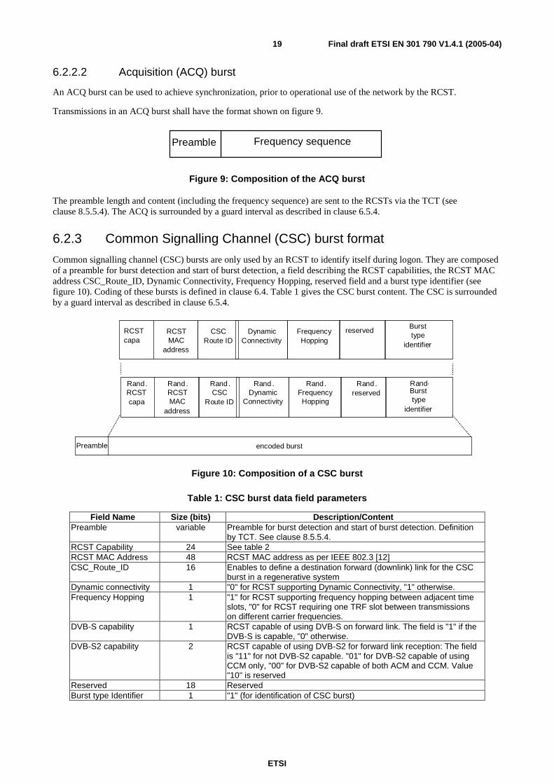
6.2.3 Common Signalling Channel (CSC) burst format
Common signalling channel (CSC) bursts are only used by an RCST to identify itself during logon. They are composed of a preamble for burst detection and start of burst detection, a field describing the RCST capabilities, the RCST MAC address CSC_Route_ID, Dynamic Connectivity, Frequency Hopping, reserved field and a burst type identifier (see figure 10). Coding of these bursts is defined in clause 6.4. Table 1 gives the CSC burst content. The CSC is surrounded by a guard interval as described in clause 6.5.4.
encoded burst Preamble
Rand . RCST capa
Rand . RCST MAC
address
RCST capa RCST
MAC address
Rand . reserved
reserved Burst type
identifier
. Burst type
identifier Rand . CSC
Route ID
CSC Route ID
Rand . Dynamic
Connectivity
Dynamic Connectivity
Rand . Frequency Hopping
Frequency Hopping
Rand
Figure 10: Composition of a CSC burst
Table 1: CSC burst data field parameters
Field Name Size (bits) Description/Content Preamble variable Preamble for burst detection and start of burst detection. Definition
by TCT. See clause 8.5.5.4. RCST Capability 24 See table 2 RCST MAC Address 48 RCST MAC address as per IEEE 802.3 [12] CSC_Route_ID 16 Enables to define a destination forward (downlink) link for the CSC
burst in a regenerative system Dynamic connectivity 1 "0" for RCST supporting Dynamic Connectivity, "1" otherwise. Frequency Hopping 1 "1" for RCST supporting frequency hopping between adjacent time
slots, "0" for RCST requiring one TRF slot between transmissions on different carrier frequencies.
DVB-S capability 1 RCST capable of using DVB-S on forward link. The field is "1" if the DVB-S is capable, "0" otherwise.
DVB-S2 capability 2 RCST capable of using DVB-S2 for forward link reception: The field is "11" for not DVB-S2 capable. "01" for DVB-S2 capable of using CCM only, "00" for DVB-S2 capable of both ACM and CCM. Value "10" is reserved
Reserved 18 Reserved Burst type Identifier 1 "1" (for identification of CSC burst)

ETSI
Final draft ETSI EN 301 790 V1.4.1 (2005-04) 20
Table 2 defines the different bit patterns within the RCST capability field. The 24-bit field is numbered from LSB to MSB using the notation b0 through b23.
Table 2: RCST capability
Parameter Bit Size Description Security mechanism 1 (b23) "1" for RCST implementing security mechanism as described in
clause 9.4. "0" otherwise. SNMP 1 (b22) "1" for RCST supporting SNMP (see clauses 8.4.2, 8.4.3 and
8.5.5.10.2). "0" otherwise. ATM connectivity 1 (b21) "1" for RCST capable of ATM connectivity (type B), "0" for not capable
(Type A). MPEG2-TS TRF 1 (b20) "1" for RCST capable of MPEG2-TS TRF, "0" for not capable. RCST boards 2 (b19-b18) Number of RCST forward link receivers: "00" for 1 receiver, "01" for 2,
"10" for more than 2, "11" reserved. RCST ACQ 1 (b17) "0" for RCST not requiring ACQ burst, "1" for ACQ required. Multi_IDU 1 (b16) "0" for single indoor unit/single outdoor unit configuration, "1" when
two or more IDUs are connected to a single ODU. S/W Version 8 (b15-b8) System Dependent. Can be used to define the RCST software
version. Freq Hopping Range 2 (b7-b6) Defines the RCST burst to burst frequency hopping range capability:
"00" for 20 MHz, "01" for 120 MHz. Other patterns System Dependent MF-TDMA 1 (b5) "1" for RCST supporting dynamic MF-TDMA. "0" for RCST supporting
fixed MF-TDMA (see clause 6.7.1). RCST Class 2 (b4-b3) System Dependent Route_ID capable 1 (b2) "1" indicates that the RCST is capable of inserting a Route_ ID in the
SAC field. "0" otherwise
RCST Mode 2 (b1-b0) "00" for Installation Mode (see clause 8.5.5.10.5), "01" for Operational Mode "10" for Reference RCST mode (can be used for measuring satellite frequency translation offset, D/L rain fade, etc.) "11" reserved.
6.2.4 Bit numbering and interpretation
The term "bit 0" shall refer to the least significant bit of a multi-bit field. The most significant bit of a k-bit unsigned field shall be designated "bit k - 1". For a signed field, "bit k - 1" shall be the sign bit and "bit k - 2" the most significant magnitude-related bit.
6.2.5 Transmission order
Fields in data structures shall be transmitted in the order in which they are defined.
Unsigned values shall be transmitted starting with the most significant bit and ending with the least significant bit.
Signed values shall be transmitted starting with the sign bit, followed by the most significant bit and ending with the least significant bit.
Bytes shall be processed MSB first.
ETSI
Final draft ETSI EN 301 790 V1.4.1 (2005-04) 21
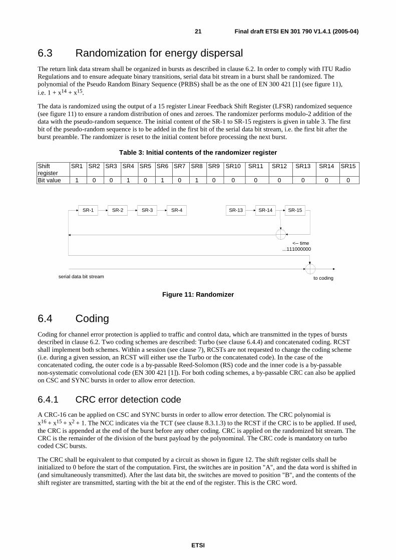
6.3 Randomization for energy dispersal The return link data stream shall be organized in bursts as described in clause 6.2. In order to comply with ITU Radio Regulations and to ensure adequate binary transitions, serial data bit stream in a burst shall be randomized. The polynomial of the Pseudo Random Binary Sequence (PRBS) shall be as the one of EN 300 421 [1] (see figure 11), i.e. 1 + x14 + x15.
The data is randomized using the output of a 15 register Linear Feedback Shift Register (LFSR) randomized sequence (see figure 11) to ensure a random distribution of ones and zeroes. The randomizer performs modulo-2 addition of the data with the pseudo-random sequence. The initial content of the SR-1 to SR-15 registers is given in table 3. The first bit of the pseudo-random sequence is to be added in the first bit of the serial data bit stream, i.e. the first bit after the burst preamble. The randomizer is reset to the initial content before processing the next burst.
Table 3: Initial contents of the randomizer register
Shift register
SR1 SR2 SR3 SR4 SR5 SR6 SR7 SR8 SR9 SR10 SR11 SR12 SR13 SR14 SR15
Bit value 1 0 0 1 0 1 0 1 0 0 0 0 0 0 0
SR-1 SR-2 SR-3 SR-4 SR-13 SR-14 SR-15
serial data bit stream to coding
...111000000<-- time
Figure 11: Randomizer
6.4 Coding Coding for channel error protection is applied to traffic and control data, which are transmitted in the types of bursts described in clause 6.2. Two coding schemes are described: Turbo (see clause 6.4.4) and concatenated coding. RCST shall implement both schemes. Within a session (see clause 7), RCSTs are not requested to change the coding scheme (i.e. during a given session, an RCST will either use the Turbo or the concatenated code). In the case of the concatenated coding, the outer code is a by-passable Reed-Solomon (RS) code and the inner code is a by-passable non-systematic convolutional code (EN 300 421 [1]). For both coding schemes, a by-passable CRC can also be applied on CSC and SYNC bursts in order to allow error detection.
6.4.1 CRC error detection code
A CRC-16 can be applied on CSC and SYNC bursts in order to allow error detection. The CRC polynomial is x16 + x15 + x2 + 1. The NCC indicates via the TCT (see clause 8.3.1.3) to the RCST if the CRC is to be applied. If used, the CRC is appended at the end of the burst before any other coding. CRC is applied on the randomized bit stream. The CRC is the remainder of the division of the burst payload by the polynominal. The CRC code is mandatory on turbo coded CSC bursts.
The CRC shall be equivalent to that computed by a circuit as shown in figure 12. The shift register cells shall be initialized to 0 before the start of the computation. First, the switches are in position "A", and the data word is shifted in (and simultaneously transmitted). After the last data bit, the switches are moved to position "B", and the contents of the shift register are transmitted, starting with the bit at the end of the register. This is the CRC word.

ETSI
Final draft ETSI EN 301 790 V1.4.1 (2005-04) 22
D13D D D
A
B A
B
Input
Output
0
Figure 12: CRC calculation
6.4.2 Reed-Solomon outer coding
A Reed-Solomon RS (N-B, K-B, T) shortened code EN 300 421 [1] derived from the original RS (255, 239, 8) code, shortened by B bytes, can be applied for some burst formats. The code generator polynomial is g(x) = (x + λ0) (x + λ1) (x + λ2) … (x + λ15), where λ = 02HEX. The field generator polynomial is
p(x) = x8 + x4 + x3 + x2 + 1. This code is similar to the one used in EN 300 421 [1].
For ATM traffic bursts the length of the encoded information word, K - B, is Natm × 53 + Np,atm. In the case that the
basic container is an MPEG2-TS packet K - B = 188 applies.
The outer code can be bypassed. The outer code is always by-passed when using Turbo codes.
If both the CRC and RS codes are used, the burst payload CRC is first computed and the RS parity bytes are then added.
6.4.3 Convolutional inner coding
Processing of the convolutional encoder shall be in accordance with EN 300 421 [1], as summarized in the following.
The return link shall allow for a range of punctured convolutional codes, based on a rate 1/2 mother convolutional code with constraint length K = 7 corresponding to 64 trellis states (see figure 13). The generator polynomials are G0 = 171
and G1 = 133 in octal representation. This choice will allow selection of the most appropriate level of error correction
for a given service or data rate. Code rates of 1/2, 2/3, 3/4, 5/6 and 7/8 shall be supported. The inner code can be bypassed. In that case, the MSB bit is affected to the I channel, the next bit to the Q channel and so on. The convolutional inner code is always by-passed when using Turbo codes.
The encoder register shall be initialized to all zeroes before encoding the first data bit.
At the end of each data block, the encoder shall be flushed by 6 zero bits. This block is called the "Postamble". The output shall be continued until the encoder is in its all-zero state. If the inner code is bypassed, then the postamble is also omitted.
The puncturing pattern period counter shall be initialized before encoding the first data bit so that the first encoded (C2,C1) symbol always corresponds to an (Y1,X1) pair in table 4.
After encoding the last 0 bit of the postamble an incomplete symbol (##,C1) can remain if the message length is not divisible by the puncturing period. In that case the missing C2 is set to 0 and the burst is terminated.

ETSI
Final draft ETSI EN 301 790 V1.4.1 (2005-04) 23
1-bitdelay
SerialInputBit-stream
Y output (133 octal)
Modulo-2 adder
Modulo-2 adder
X output (171 octal)
1-bitdelay
1-bitdelay
1-bitdelay
1-bitdelay
1-bitdelay
Figure 13: Convolutional code of rate 1/2
The punctured convolutional code shall be used as given in table 4, according to EN 300 421 [1].
Table 4: Punctured code definition
Original code Code rates 1/2 2/3 3/4 5/6 7/8
K
G1 (X)
G2 (Y)
P dfree
P dfree
P dfree P dfree
P dfree
7
171OCT
133OCT
X: 1 Y: 1
C1 = X1 C2 = Y1
10
X: 1 0 Y: 1 1
C1 = X1 Y2 Y3 C2 = Y1 X3 Y4
6
X: 1 0 1 Y: 1 1 0
C1 = X1 Y2 C2 = Y1 X3
5
X: 1 0 1 0 1 Y: 1 1 0 1 0
C1 = X1 Y2 Y4 C2 = Y1 X3 X5
4
X: 1 0 0 0 1 0 1 Y: 1 1 1 1 0 1 0
C1 = X1 Y2 Y4 Y6C2 = Y1 Y3 X5 X7
3
NOTE: 1 = transmitted bit. 0 = non transmitted bit.
6.4.4 Turbo code
The Turbo encoder is depicted in figure 14. It uses a double binary Circular Recursive Systematic Convolutional (CRSC) code. The MSB bit of the first byte after the burst preamble is assigned to A, the next bit to B and so on for the remaining of the burst content.
The encoder is fed by blocks of k bits or N couples (k = 2 × N bits). N is a multiple of 4 (k is a multiple of 8).
The polynomials defining the connections are described in octal and symbolic notations as follows:
- for the feedback branch: 15 (in octal), equivalently 1 + D + D3 (in symbolic notation);
- for the Y parity bits: 13, equivalently 1 + D2 + D3;
- for the W parity bits: 11, equivalently 1 + D3.
The input A bit is connected to tap "1" of the shift register and the input B bit is connected to the taps "1", D and D2.
First, the encoder (after initialization by the circulation state 1CS , see clause 6.4.4.2) is fed by the sequence in the
natural order (switch on position 1) with incremental address i = 0, ...N - 1. This first encoding is called C1 encoding.
Then the encoder (after initialization by the circulation state 2CS , see clause 6.4.4.2) is fed by the interleaved sequence
(switch in position 2) with incremental address j = 0, ...N-1. This second encoding is called C2 encoding. The function
Π(j) that gives the natural address i of the considered couple, when reading it at place j for the second encoding, is given in clause 6.4.4.1.

ETSI
Final draft ETSI EN 301 790 V1.4.1 (2005-04) 24
N=k/2couples of data
Permutation(k/2)
Π
codeword
puncturing
W1 or 2 Y1 or 2
B
2
A
1S1
A
B
YW
Systematic part
Redundancy part
S2 S3
Figure 14: Encoder block diagram (turbo code)
6.4.4.1 Description of the turbo code permutation
The permutation is done on two levels, the first one inside the couples (level 1), the second one between couples (level 2):
Set the permutation parameters P0, P1, P2 and P3
j = 0, ...N - 1
level 1
if j mod. 2 = 0, let (A,B) = (B,A) (invert the couple).
level 2
- if j mod. 4 = 0, then P = 0;
- if j mod. 4 = 1, then P = N/2 + P1;
- if j mod. 4 = 2, then P = P2;
- if j mod. 4 = 3, then P = N/2 + P3.
i = P0 × j + P + 1 mod. N
Table 5 provides the combinations of the default parameters to be used. Those parameters can be updated by the TCT (see clause 8.5.5.4). The interleaving relations satisfy the odd/even rule (i.e. when j is even, i is odd and vice-versa) that enables the puncturing patterns to be identical for both encodings.
Table 5: Turbo code permutation parameters
Frame size in couples P0 {P1, P2, P3}
N = 48 (12 bytes) 11 {24,0,24} N = 64 (16 bytes) 7 {34,32,2} N = 212 (53 bytes) 13 {106,108,2} N = 220 (55 bytes) 23 {112,4,116} N = 228 (57 bytes) 17 {116,72,188} N = 424 (106 bytes) 11 {6,8,2} N = 432 (108 bytes) 13 {0,4,8} N = 440 (110 bytes) 13 {10,4,2} N = 848 (212 bytes) 19 {2,16,6} N = 856 (214 bytes) 19 {428,224,652} N = 864 (216 bytes) 19 {2,16,6} N = 752 (188 bytes) 19 {376,224,600}

ETSI
Final draft ETSI EN 301 790 V1.4.1 (2005-04) 25
6.4.4.2 Determination of the circulation states
The state of the encoder is denoted S (0 ≤ S ≤ 7) with S = 4 × s1 + 2 × s2 + s3 (see figure 14). The circulation states SC1
and SC2 are determined by the following operations:
1) initialize the encoder with state 0. Encode the sequence in the natural order for the determination of SC1 or in
the interleaved order for the determination of SC2 (without producing redundancy). In both cases, the
successive states of the encoder are denoted S0k, 0 ≤ k ≤ N. S0
0 is the initialization state and S0N is the final
state (i.e. the state of the encoder after all the N couples have been encoded).
2) according to the length N of the sequence, use the following correspondence to find SC1 or SC2 (table 6).
Table 6: Circulation state correspondence table
0NS →→→→
↓ N mod. 7
0
1
2
3
4
5
6
7
1 SC = 0 SC = 6 SC = 4 SC = 2 SC = 7 SC = 1 SC = 3 SC = 5
2 SC = 0 SC = 3 SC = 7 SC = 4 SC = 5 SC = 6 SC = 2 SC = 1
3 SC = 0 SC = 5 SC = 3 SC = 6 SC = 2 SC = 7 SC = 1 SC = 4
4 SC = 0 SC = 4 SC = 1 SC = 5 SC = 6 SC = 2 SC = 7 SC = 3
5 SC = 0 SC = 2 SC = 5 SC = 7 SC = 1 SC = 3 SC = 4 SC = 6
6 SC = 0 SC = 7 SC = 6 SC = 1 SC = 3 SC = 4 SC = 5 SC = 2
6.4.4.3 Rates and puncturing map
Seven code rates are defined for the Turbo mode: R = 1/3, 2/5, 1/2, 2/3, 3/4, 4/5, 6/7. This is achieved through selectively deleting the parity bits (puncturing). The puncturing patterns of table 7 are applied. These patterns are identical for both codes C1 and C2 (deleting is always done in couples) and are repeated an integer or fractional number
of times, as appropriate. The puncturing rate is indicated to the RCSTs via the TCT (see clause 8.5.5.4).
Rates 1/3, 2/5, 1/2, 2/3 and 4/5 are exact ones, independently of the block size. Rates 3/4 and 6/7 are exact ones only if N is a multiple of 3. In other cases, the actual rates are very slightly lower than the nominal ones.
Depending on the code rate, the length of the encoded block is:
• 2N + M for R < 1/2, with:
- M = N for R = 1/3;
- M = N/2 for R = 2/5.
• N + M for R ≥ 1/2, with:
- M = N for R = 1/2;
- M = N/2 for R = 2/3;
- for R = 3/4.
• M = N/3 (if N mod. 3 = 0); or
• M = (N - 4) / 3 + 2 (if N mod. 3 = 1); or
• M = (N - 8) / 3 + 3 (if N mod. 3 = 2).
- M = N/4 for R = 4/5;
- for R = 6/7.

ETSI
Final draft ETSI EN 301 790 V1.4.1 (2005-04) 26
• M = N/6 (if N mod. 3 = 0); or
• M = (N - 4) / 6 + 1 (if N mod. 3 = 1); or
• M = (N - 8) / 6 + 2 (if N mod. 3 = 2).
Table 7: Puncturing patterns for Turbo codes "1"=keep
1
13/1W
Y
01
115/2
W
Y
0
12/1
W
Y
00
013/2W
Y
000
0014/3
W
Y
0000
00015/4
W
Y
000000
0000017/6
W
Y
6.4.4.4 Order of transmission and mapping to QPSK constellation
Two orders of transmission are allowed:
- in the natural order, all couples (A,B) are transmitted first, followed by all couples (Y1,Y2) that remain after
puncturing and then all couples (W1,W2) that remain after puncturing (see figure 15);
- in the reverse order, the couples (Y1,Y2) are transmitted first, in their natural order, followed by the couples
(W1,W2), if any, and then finally by the couples (A,B).
Each couple is mapped to one QPSK constellation point as shown in figure 17. In figure 15, the row with the A symbols is mapped on the I channel (C1 in figure 17).
The order of transmission is signalled by the NCC as an inner code parameter in the Time Slot Composition Table (see clause 8.5.5.4).
A
B
0
A
B 1
A
B
2
A
B
N-2
A
B N-1
Y1
N
Y2
Y1
Y2 N+1
Y1
2N-2
Y2
Y1
Y2 2N-1
W1
2N
W2 2N+1
W1
W2
Y1
Y2
N+2
W1
W2
2N+2
W1
W2
W1
W2
2N+M-2
2N+M-1
n
R<1/2
A
B
0
A
B 1
A
B
2
A
B
N-2
A
B N-1
Y1
N
Y2
Y1
Y2 N+1
Y1
N+M-2
Y2
Y1
Y2
Y1
Y2
N+2
n
R≥1/2
N+M-1
Figure 15: Encoded blocks (natural order)

ETSI
Final draft ETSI EN 301 790 V1.4.1 (2005-04) 27
6.5 Modulation The signal shall be modulated using QPSK, with baseband shaping as described in clauses 6.5.1 to 6.5.4.
6.5.1 Bit mapping to QPSK constellation
Mapping into the QPSK constellation shall be as follows.
The preamble shall be configurable and indicated to the RCST through the TCT, as described in clause 8.5.5.4.
Immediately after the preamble insertion, the outputs C1 and C2 of the encoder shall be sent without modification to the QPSK bit mapper (see figure 16).
C1
C2
I
Q
bit mapping
constellation
to QPSKBaseband
shaping
Quadrature
Modulation
Preamble
insertion
Figure 16: Processing after the encoder
Conventional Gray-coded QPSK modulation with absolute mapping (no differential coding) shall be used. Bit mapping in the QPSK constellation shall follow figure 17. If the normalization factor 1/√2 is applied to the I and Q components, the corresponding average energy per symbol becomes equal to 1.
C1=0
Q
I
C1=0C1=1
1
1
C2=0
C2=1
C1=1C2=0
C2=1
Figure 17: Bit mapping into QPSK constellation
The output C1 of the channel coding shall be mapped to the I channel of the modulation. The output C2 shall be mapped to the Q channel of the modulation.
Following the modulation process, the spectrum of the QPSK signal shall not be inverted.
6.5.2 Baseband shaping and quadrature modulation
Prior to modulation, the I and Q signals (mathematically represented by a succession of Dirac delta functions, multiplied by the amplitudes I and Q, spaced by the symbol duration TS = 1/RS) shall be square root raised cosine filtered. The roll-off factor shall be 35 % as indicated by the TCT (see clause 8.5.5.4). The baseband square root raised cosine filter shall have a theoretical function defined by the following expression:
( ) ( )
( ) ( ) ( ) ( )( ) ( )α
ααα
πα
+>=
+≤≤−−
+=
−<=
1for0
11for2
sin2
1
2
1
1for1
N
NNN
N
N
fffH
ffff
fffH
fffH
where fT
RN
s
s= =1
2 2 is the Nyquist frequency and α is the roll-off factor.

ETSI
Final draft ETSI EN 301 790 V1.4.1 (2005-04) 28
At the RCST antenna output (using a large output back-off), the allowed spectrum and group delay variation shall be according to the mask given in EN 300 421 [1] for every return link symbol rate supported by the terminal.
6.5.3 EIRP control
The RCST shall be capable of adjusting the transmit EIRP in steps of nominally 0,5 dB over the operating range specified by the manufacturer. Over this range, the terminal output power change shall reflect a power adjust command to within 0,5 dB or to within 20 % in dB of the requested adjustment, whichever is less stringent (see clauses 8.5.5.9 and 8.5.5.10.3).
6.5.4 Guard time
Each burst is surrounded by a guard time which allows for RCST power switch-off transient and system timing errors. The guard time is allocated by the NCC as an implicit element of the TCT. The guard time is network dependant and is determined by overall system requirements. On optional MPEG2-TS TRF bursts, the guard time shall be shorter than half an MPEG2-TS packet.
6.6 MAC messages All methods described below can be used by RCSTs for capacity requests and M&C messages. The four first methods are based on the Satellite Access Control (SAC) field and the last one allows encapsulation in ATM or MPEG-2 Data Units called Data Unit Labelling Method (DULM). One or more of the methods may be employed in a Satellite Interactive Network. For the particular implementation, the RCSTs are configured at the time of logon by the logon initialize descriptor (see clause 8.5.5.10.4) that is transmitted in a TIM.
6.6.1 Methods based on the Satellite Access Control (SAC) field
6.6.1.1 SAC field composition
The SYNC, the optional prefix attached to ATM TRF bursts and the optional MPEG TRF burst may contain the Satellite Access Control (SAC) field composed of signalling information added by the RCST for the purpose of requesting capacity on the session, or other additional MAC information.
The SAC is composed of optional sub-fields that are defined in table 8.
The SAC field configuration for specific SYNC (see clauses 6.6.1.3 and 6.6.1.4) or ATM TRF (see clause 6.6.1.2) time slots is signalled by the NCC in the TCT as described in clause 8.5.5.4.
The optional SAC field configuration of MPEG bursts is signalled directly within the TS packet of the specific MPEG TRF burst as defined in clause 6.6.1.5.
NOTE: The symbols and abbreviations, and the method of describing syntax used in the present document are the same as those defined in clauses 2.2 and 2.3 of ISO/IEC 13818-1 [9].

ETSI
Final draft ETSI EN 301 790 V1.4.1 (2005-04) 29
Table 8: Syntax of the SAC field
No. of bits Syntax (see note) Reserved Information
Information Mnemonic
SAC_field() { if (Route_ID_flag == 0) Route_ID 16 uimsbf if (request_flag == 1) for (i=0; i<=capacity_requests_number; i++) {
Capacity_Request { Scaling_Factor 1 bslbf Capacity_Request_Type 3 bslbf Channel_ID 4 uimsbf Capacity_Request_Value 8 uimsbf } } if (M_and_C_flag == 1) M_and_C_Message 16 bslbf if (Group_ID_flag == 1) Group_ID 8 uimsbf if (Logon_ID_flag == 1) Logon_ID 16 uimsbf if (ACM_flag == 0) { ACM { CNI 8 uimsbf MODCOD_RQ 8 bslbf } } Pad_Bytes see text uimsbf } NOTE: For SYNC and ATM TRF bursts, the sub-fields used in test statements (Route_ID_Flag,
request_flag, capacity_requests_number, M_and_C_flag, Group_ID_flag, Login_ID_flag and ACM_flag) refer to the subfields of the specific timeslot of the TCT for which the RCST has to transmit a SAC field as defined in clause 8.5.5.4.
For MPEG TRF bursts carrying a SAC field, sub-fields used in test statements refer to the subfields of the SAC_composition of the Adaptation Field Private Data as defined in clause 6.6.1.5.
Semantics for the SAC field:
- Route_ID: This 16-bit field defines a destination forward (downlink) link for the prefixed payload in a regenerative system. Values are system dependent.
- Capacity_Request: Each capacity request is composed of the following sub-fields:
- Scaling_Factor: This 1-bit sub-field defines the scaling factor of the Capacity_Request_Value sub-field (see table 9).
Table 9: Scaling_Factor
Value Scaling factor 0 1 1 16
- Capacity_Request_Type: This is a 3-bit sub-field specifying the category of capacity request (see table 10). The capacity categories are described in clause 6.8.
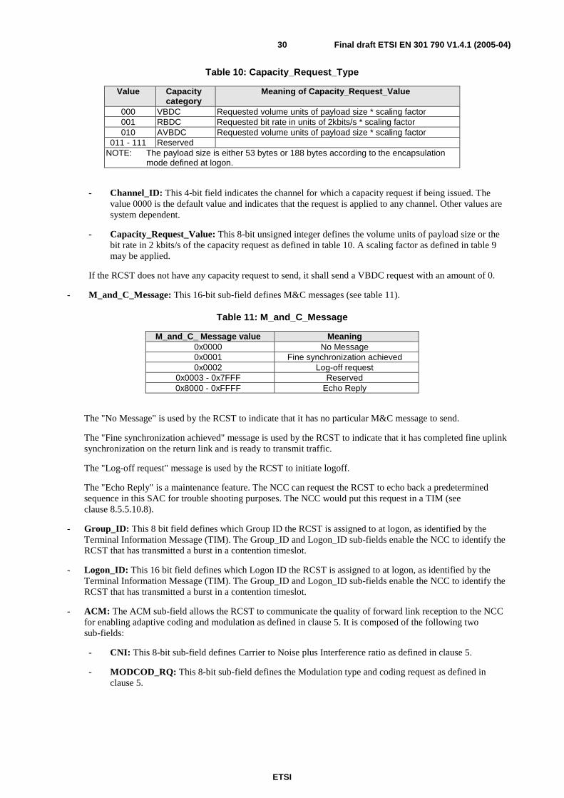
ETSI
Final draft ETSI EN 301 790 V1.4.1 (2005-04) 30
Table 10: Capacity_Request_Type
Value Capacity category
Meaning of Capacity_Request_Value
000 VBDC Requested volume units of payload size * scaling factor 001 RBDC Requested bit rate in units of 2kbits/s * scaling factor 010 AVBDC Requested volume units of payload size * scaling factor
011 - 111 Reserved NOTE: The payload size is either 53 bytes or 188 bytes according to the encapsulation
mode defined at logon.
- Channel_ID: This 4-bit field indicates the channel for which a capacity request if being issued. The value 0000 is the default value and indicates that the request is applied to any channel. Other values are system dependent.
- Capacity_Request_Value: This 8-bit unsigned integer defines the volume units of payload size or the bit rate in 2 kbits/s of the capacity request as defined in table 10. A scaling factor as defined in table 9 may be applied.
If the RCST does not have any capacity request to send, it shall send a VBDC request with an amount of 0.
- M_and_C_Message: This 16-bit sub-field defines M&C messages (see table 11).
Table 11: M_and_C_Message
M_and_C_ Message value Meaning 0x0000 No Message 0x0001 Fine synchronization achieved 0x0002 Log-off request
0x0003 - 0x7FFF Reserved 0x8000 - 0xFFFF Echo Reply
The "No Message" is used by the RCST to indicate that it has no particular M&C message to send.
The "Fine synchronization achieved" message is used by the RCST to indicate that it has completed fine uplink synchronization on the return link and is ready to transmit traffic.
The "Log-off request" message is used by the RCST to initiate logoff.
The "Echo Reply" is a maintenance feature. The NCC can request the RCST to echo back a predetermined sequence in this SAC for trouble shooting purposes. The NCC would put this request in a TIM (see clause 8.5.5.10.8).
- Group_ID: This 8 bit field defines which Group ID the RCST is assigned to at logon, as identified by the Terminal Information Message (TIM). The Group_ID and Logon_ID sub-fields enable the NCC to identify the RCST that has transmitted a burst in a contention timeslot.
- Logon_ID: This 16 bit field defines which Logon ID the RCST is assigned to at logon, as identified by the Terminal Information Message (TIM). The Group_ID and Logon_ID sub-fields enable the NCC to identify the RCST that has transmitted a burst in a contention timeslot.
- ACM: The ACM sub-field allows the RCST to communicate the quality of forward link reception to the NCC for enabling adaptive coding and modulation as defined in clause 5. It is composed of the following two sub-fields:
- CNI: This 8-bit sub-field defines Carrier to Noise plus Interference ratio as defined in clause 5.
- MODCOD_RQ: This 8-bit sub-field defines the Modulation type and coding request as defined in clause 5.

ETSI
Final draft ETSI EN 301 790 V1.4.1 (2005-04) 31
- Pad_bytes: If the SAC field length (as given by Burst.SAC_Length) is larger than the sum of its sub-field lengths, then this field contains as many 8-bit sub-fields with the value "0" as required to match the SAC field length.
When several of the SAC sub-fields are present, they appear in the order defined in table 8.
6.6.1.2 Prefix method mechanism
This mechanism is based on an optional Np,atm bytes prefix attached to ATM traffic bursts. If used, the prefix carries
control and management information from the RCSTs to the NCC. This mechanism is supported by the SAC route_ID and request sub-fields (see clause 6.6.1.1) when appended to ATM Traffic bursts (see clause 6.2.1.1).
6.6.1.3 Mini-slot method
This mechanism is based on a periodic assignment to logged-on RCSTs of bursts smaller than traffic timeslots. It carries control and management information from the RCSTs to the NCC and is used also for maintaining RCST synchronization. This mechanism is supported by the SAC request sub-field (see clause 6.6.1.1) used in SYNC bursts (see clause 6.2.2.1).
6.6.1.4 Contention based mini-slot method
As per the method described in the previous clause, but the mini-slot can be accessed by a group of RCSTs on a contention basis. This mechanism is supported by the SAC request, Group_ID and Logon_ID sub-fields (see clause 6.6.1.1) used in SYNC bursts (see clause 6.2.2.1).
6.6.1.5 MPEG Adaptation Field Method (MPAF) (option)
This method is based on using the private data bytes of the MPEG layer adaptation field to carry a SAC message. The adaptation field, if used, carries control and management information from the RCST to the NCC. The availability of the method is not signalled in the TCT but directly in the MPEG header of the MPEG TRF burst. The functionality shall be configurable in the RCST to ensure compatibility with gateways not implementing the option.
The format of TS packet carrying a SAC in the adaptation field shall be according to ISO/IEC 13818-1 [9], clause 2.4.3. Specifically, the fields shall be coded as follows:
- sync_byte: as defined in [9];
- transport_error_indicator: as defined in [9];
- payload_unit_start_indicator: set to "1" if the TS packet includes user data in the payload section following the adaptation field, or set to "0" if the TS packet carries no payload section;
- transport_priority: set to "0";
- PID: set to the assigned PID used for return link traffic;
- transport_scrambling_control: as defined in [9];
- adaptation_field_control: set to "10" whenever a SAC message only is being sent (no payload) and set to "11" when the adaptation field is followed by a payload section;
- adaptation_field(): as defined below.

ETSI
Final draft ETSI EN 301 790 V1.4.1 (2005-04) 32
When the TS packet does not carry a SAC, the adaptation field is coded as per ISO/IEC 13818-1 [9], clause 2.4.3.4 with the following field values:
- adaptation_field_length: set to "2 + transport_private_data_length";
- discontinuity_indicator: set to "0";
- random_access_indicator: set to "0";
- elementary_stream_priority_indicator: set to "0";
- PCR_flag: set to "0";
- OPCR_flag: set to "0";
- splicing_point_flag: set to "0";
- transport_private_data_flag: set to "1";
- adaptation_field_extension_flag: set to "0";
- transport_private_data_length: set to "number of private_data_bytes that follow";
- private_data_byte: coded as shown in the table blow.
The private data bytes of the adaptation field shall be coded as defined in table 12.
Table 12: Syntax of the MPEG Adaptation Field Private Data field
No. of bits Syntax Reserved Information
Information Mnemonic
Adaptation_Field_Private_data() { SAC_composition { Route_ID_flag 1 bslbf ACM_flag 1 bslbf SAC_length 1 5 uimsbf request_flag 1 bslbf M_and_C_flag 1 bslbf Group_ID_flag 1 bslbf Logon_ID_flag 1 bslbf capacity_requests_number 3 bslbf Reserved 1 bslbf } SAC_field as defined in clause 6.6.1.1 n }
Semantics for the Adaptation Field Private Data field:
- SAC_composition: the semantics for the sub-fields (Route_ID_flag, ACM_flag, SAC_length, request_flag, M_and_C_flag, Group_ID_flag, Logon_ID_flag, capacity_requests_number) in the adaptation field private data is equal to the corresponding fields in the TCT (see clause 8.5.5.4).
- SAC_field: as defined in clause 6.6.1.1.
6.6.2 Data Unit Labelling Method (DULM)
The Data Unit Labelling Method (DULM) is a "message-based" method that allows RCSTs to transmit control and/or management information to the NCC in the payload of the Data Units already assigned to them in TRF bursts. These Data Units are either ATM cells or MPEG TS packets, depending on the encapsulation mode of the RCST, as described in clause 6.2.1.
The sequence of these "special" TRF bursts from an RCST to the NCC constitutes a dedicated virtual channel named CTRL/MNGM. This virtual channel can thus be utilized to support message-based delivery of control (e.g. bandwidth requests) and/or management information, possibly in combination with other methods described in this clause.

ETSI
Final draft ETSI EN 301 790 V1.4.1 (2005-04) 33
The use of the CTRL/MNGM virtual channel may be at the initiative of the NCC or of the RCST. For instance, an active RCST may insert a bandwidth request in an already assigned timeslot. The NCC may request status information from an RCST, and allocate timeslots to a terminal for the CTRL/MNGM channel.
6.6.2.1 DULM with ATM-formatting
For RCSTs, using ATM TRF bursts as defined in clause 6.2.1.1, the CTRL/MNGM virtual channel shall be identified by a unique value in the Data Unit header, with the MSB of the PT field set to 1 so as to allow discrimination from normal traffic information (see clause 8.1.1).
A DULM message shall be composed of an integer number (between 1 and 64) of Information Elements (IE).
Each IE shall have the format described in figure 18, and be made of 2 bytes of header (IE type and IE length) plus a body of n bytes, with n between 1 and 512. A given DULM message may be composed of IEs of different lengths.
IE type IE length IE body
7 bits 9 bits n bytes
IE 1 IE 2 IE m. . .
DULM message
Figure 18: DULM message with ATM TRF bursts
The DULM message shall then be transmitted using standard AAL5 mechanisms, as specified in ITU-T Recommendation I.363-5 [18].

ETSI
Final draft ETSI EN 301 790 V1.4.1 (2005-04) 34
The Information Elements shall be as defined in table 13.
Table 13: IEs for the ATM TRF case
IE type IE length (see note 1)
IE body
0x00 Capacity Request 2 bytes As per clause 6.6.1.1 0x01 M&C 2 bytes As per clause 6.6.1.1 0x02 Group_and_Logon_ID 3 bytes As per clause 6.6.1.1
(see note 2) 0x03 Message Header 4 bytes See description below 0x04 Cause 2 bytes See description below 0x05 Channel_ ID 1 byte See description below 0x06 Source Address 6 bytes See description below 0x07 Destination Address 6 bytes See description below 0x08 Forward Stream Identifier 3 bytes See description below 0x09 Return Stream Identifier 3 bytes See description below 0x0A Type 1 byte See description below 0x0B Forward Profile 3 bytes See description below 0x0C Return Profile 3 bytes See description below 0x0D Security Sign-on Response 8 bytes As per clause 9.4.9.2 0x0E Route_ID 2 bytes See description below 0x0F - 0x1E Reserved 0x1F Wait As per clause 9.4.9.9 0x20 - 0x30 Reserved 0x31 Main Key Exchange Response As per clause 9.4.9.4 0x32 Reserved 0x33 Quick Key Exchange Response As per clause 9.4.9.6 0x34 Reserved 0x35 Explicit Key Exchange Response As per clause 9.4.9.8 0x36 ACM 2 bytes as per clause 6.6.1.1 0x37 - 0x7F Reserved NOTE 1: "IE length": length (in bytes) of the IE body. NOTE 2: Group_and_Logon_ID: concatenation of the 1-byte Group_ID and the 2-byte Logon_ID fields,
in this order.
IE type description:
• Message Header: it identifies the type of message, sets the total length in byte of the message and identifies the connection affected by the connection control signalling.
• Cause: it conveys the reason for the reject of a previous request.
• Channel_ID: defined and utilized according to the present document.
• Source Address: it is the address of the calling end point.
• Destination Address: it is the address of the called end point(s).
• Forward stream identifier: it identifies a single forward information flow pertaining to the connection; it is either one { VPI, VCI} pair or a single PID, depending on the ATM or MPEG-2 nature of the information flow.
• Return stream identifier: it identifies a single return information flow pertaining to the connection; it is either one { VPI, VCI} pair or a single PID, depending on the ATM or MPEG-2 nature of the information flow.
• Type: it describes the connection configuration in terms of direction and casting.
• Forward Profile: it describes the priority and the overall amount of resources of the forward streams of the connection.

ETSI
Final draft ETSI EN 301 790 V1.4.1 (2005-04) 35
• Return Profile: it describes the priority and the overall amount of resources of the return streams of the connection.
• Route_ID: see clause 6.6.1.1.
6.6.2.2 DULM with MPEG-formatting
For the RCSTs using the optional MPEG TRF bursts, a CTRL/MGNM PID shall be used in the header of CTRL/MNGM bursts. This PID is obtained by the RCST during the logon procedure (see clause 8.5.5.10.4).
DULM messages shall use the transport mechanism described below, and illustrated in figure 19.
GROUP ID
LOGON ID(2 bytes)
IE TYPE (1)
Segment Length (1)
0 = IE finishes in this data unit1 = IE continues in next data unit
0 = New IE1 = Continuation of IE
0 = Last IEs in this data unit1 = Another IE follows
N/C F/C L/C
MPEG HEADER(CTRL/MNGM PID)
IE (1)
IE (1)
IE (1)
IE (1)
IE TYPE (2)
Segment Length (2)
N/C F/C L/C
IE (2)
MSB
Figure 19: DULM over optional MPEG packets
The first 3 bytes of each Data Unit payload shall contain the RCST Group_ID and Logon_ID. Then one or more Information Elements (IE) follow with the structure described hereafter.
The first byte of an IE contains 4 fields:
- the [IETYPE] field is contained in the first 5 bits. It contains the IE type, as defined in table 14;
- the [N/C] is contained in the 6th bit. If [N/C] = 0 the IE is starting in this Data Unit, if [N/C] = 1 the IE is continued from the previous CTRL/MNGM Data Unit from the same RCST;
- the [F/C] is contained in the 7th bit. If [F/C] = 0 the IE will finish in this CTRL/MNGM Data Unit, if [F/C] = 1 the IE will continue in the next CTRL/MNGM Data Unit from the same RCST;
- the [L/C] is contained in the 8th bit. If [L/C] = 0 the IE is the last of the CTRL/MNGM Data Unit, if [L/C] = 1 another IE follows in the same CTRL/MNGM Data Unit.
The second byte contains the [SLENG] field. It indicates the segment length in number of bytes, defined as the part of the IE contained in the current Data Unit.
The following bytes contain the variable-length fragment.
NOTE: If the IE spans over several CTRL/MNGM Data Units, the IE header (IETYPE, [N/C], [F/C], [L/C], segment_length) is duplicated on all Data Units.
Padding bytes set to all "0"s shall be appended to the last IE of a CTRL/MNGM data unit.
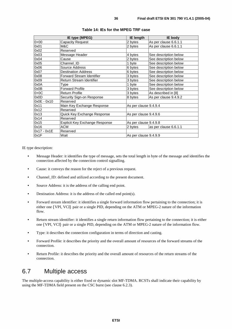
ETSI
Final draft ETSI EN 301 790 V1.4.1 (2005-04) 36
Table 14: IEs for the MPEG TRF case
IE type (MPEG) IE length IE body 0×00 Capacity Request 2 bytes As per clause 6.6.1.1 0x01 M&C 2 bytes As per clause 6.6.1.1 0x02 Reserved 0x03 Message Header 4 bytes See description below 0x04 Cause 2 bytes See description below 0x05 Channel_ID 1 byte See description below 0x06 Source Address 6 bytes See description below 0x07 Destination Address 6 bytes See description below 0x08 Forward Stream Identifier 3 bytes See description below 0x09 Return Stream Identifier 3 bytes See description below 0x0A Type 1 byte See description below 0x0B Forward Profile 3 bytes See description below 0×0C Return Profile 3 bytes As described in [8] 0x0D Security Sign-on Response 8 bytes As per clause 9.4.9.2 0x0E - 0x10 Reserved 0x11 Main Key Exchange Response As per clause 9.4.9.4 0x12 Reserved 0x13 Quick Key Exchange Response As per clause 9.4.9.6 0x14 Reserved 0x15 Explicit Key Exchange Response As per clause 9.4.9.8 0x16 ACM 2 bytes as per clause 6.6.1.1 0x17 - 0x1E Reserved 0x1F Wait As per clause 9.4.9.9
IE type description:
• Message Header: it identifies the type of message, sets the total length in byte of the message and identifies the connection affected by the connection control signalling.
• Cause: it conveys the reason for the reject of a previous request.
• Channel_ID: defined and utilized according to the present document.
• Source Address: it is the address of the calling end point.
• Destination Address: it is the address of the called end point(s).
• Forward stream identifier: it identifies a single forward information flow pertaining to the connection; it is either one { VPI, VCI} pair or a single PID, depending on the ATM or MPEG-2 nature of the information flow.
• Return stream identifier: it identifies a single return information flow pertaining to the connection; it is either one { VPI, VCI} pair or a single PID, depending on the ATM or MPEG-2 nature of the information flow.
• Type: it describes the connection configuration in terms of direction and casting.
• Forward Profile: it describes the priority and the overall amount of resources of the forward streams of the connection.
• Return Profile: it describes the priority and the overall amount of resources of the return streams of the connection.
6.7 Multiple access The multiple-access capability is either fixed or dynamic slot MF-TDMA. RCSTs shall indicate their capability by using the MF-TDMA field present on the CSC burst (see clause 6.2.3).

ETSI
Final draft ETSI EN 301 790 V1.4.1 (2005-04) 37
6.7.1 MF-TDMA
The satellite access scheme is Multi-Frequency Time Division Multiple Access (MF-TDMA). MF-TDMA allows a group of RCSTs to communicate with a gateway using a set of carrier frequencies, each of which is divided into time-slots. The NCC will allocate to each active RCST a series of bursts, each defined by a frequency, a bandwidth, a start time and a duration.
6.7.1.1 Fixed MF-TDMA
In Fixed-Slot MF-TDMA, the bandwidth and duration of successive traffic slots used by an RCST is fixed, as illustrated in figure 20 where the arrow indicates a typical sequence of slots assigned by the NCC to one RCST. In this case, TCT parameters (see clause 8.5.5.4) defining the burst parameters (symbol_rate, inner_code_type, inner_code_ordering, outer_coding, inner_code_puncturing, modulation and baseband shaping) of a superframe are fixed. A fixed MF-TDMA RCST can send a mix of SYNC and single size TRF bursts provided that the burst parameters fulfil the previous requirement. If the NCC requests a change in these parameters, then they will apply to a new superframe with a delay as described in clause 6.7.2.3.
Frequency
Time
Figure 20: Fixed-slot MF-TDMA
6.7.1.2 Dynamic MF-TDMA (Optional)
Dynamic-Slot MF-TDMA uses additional RCST flexibility to vary the bandwidth and duration of successive slots allocated to an RCST. In addition to changing carrier frequency and burst duration, the RCST may also change transmission rate and coding rate between successive bursts. The advantage of the more flexible RCST is more efficient adaptation to the widely varying transmission requirements typical of multimedia. The basic principle of the flexible RCST is illustrated in figure 21, where the arrows show an RCST using successive slots with different bandwidths and durations.
Frequency
Time
Figure 21: Optional dynamic-Slot MF-TDMA, using a flexible RCST
6.7.1.3 Frequency range
RCSTs have a specific frequency range for the frequency hopping from time-slot to time-slot. This frequency hopping range is communicated from an RCST to the NCC in a CSC burst during logon procedure (see clause 6.2.3). The frequency hopping capability of individual RCSTs shall be at the manufacturer's discretion and shall be at least 20 MHz (i.e. ±10 MHz around centre frequency).
The frequency agility is specified in terms of short term frequency hopping and long term frequency tuning.

ETSI
Final draft ETSI EN 301 790 V1.4.1 (2005-04) 38
Frequency hopping covers changes of frequency between adjacent slots in time. The settling time between bursts shall not exceed the guard interval defined in clause 6.5.4. The settling time is the period required to achieve the frequency tolerance given in clause 6.1.2. As an option, a manufacturer can declare that the terminal needs a full TRF slot between transmissions on different carrier frequencies within that range. The selected option shall be signalled in the CSC burst.
Frequency tuning covers the change in centre frequency of hop ranges. The settling time shall not exceed 1 s.
6.7.2 Segmentation of the return link capacity
In a Satellite Interactive Network, the timeslots of the return link are organized and numbered so that the network is able to allocate them to individual RCSTs.
6.7.2.1 Superframes
A superframe is a portion of time and frequency of the return link.
Within a Satellite Interactive Network, a Superframe_ID identifies the return link resources accessed by a given set of RCSTs. Figure 21 shows a typical example whereby superframe_IDs are indeed separate sets of carrier frequencies.
Superframe counter
14
time
frequency Superframe_id 1
Superframe_id 2 Superframe
counter 236
Superframe counter
237
Superframe counter
238
Superframe counter
239
Superframe counter
15
Superframe counter
16
Figure 22: Typical example of superframes of a Satellite Interactive Network
In a Satellite Interactive Network, the global return link capacity may be segmented amongst sets of RCSTs, and the network will then separately manage several Superframe_IDs. In the following, we only consider one Superframe_ID.
As shown by figure 22, the consecutive superframes of a given Superframe_ID are contiguous in time. Each occurrence of a superframe in time is labelled with a number called "superframe_counter".
For each superframe (of a given Superframe_ID), allocation of timeslots is communicated to the RCSTs via the TBTP table (see clause 8.5.5.7). An RCST is allowed to transmit bursts only in timeslots which were allocated to it ("dedicated access"), or on random-access timeslots ("contention access").
NOTE 1: Some timeslots (like the ACQ and the SYNC bursts, see clauses 6.2.2.1 and 6.2.2.2) can be assigned to RCSTs on the basis of a period which is much longer than the superframe via individual TIM messages (see clauses 8.5.5.10.5 and 8.5.5.10.6). The period for these timeslots will be system dependent, but typically in the order of one second.
The superframe duration is therefore the elementary period of time for the assignment of resources to terminals.
NOTE 2: Some timeslots (like the SYNC bursts, see clause 6.2.2.1) can be assigned to RCSTs on the basis of a period which is much longer than the superframe duration, in the order of one second (system-dependent).

ETSI
Final draft ETSI EN 301 790 V1.4.1 (2005-04) 39
6.7.2.2 Frames
A superframe is composed of frames, themselves composed of timeslots. The frame is at an intermediate level between the superframe and the timeslots. It is introduced for reasons of signalling efficiency (on the forward link signalling). The frame duration is not used as the basis of any timeslot allocation process.
time
frequency
0
2
3
F_nb6
1
4
7 8
5
Superframe_counter 237
F_nb
F_nb
F_nb
F_nb
F_nb
F_nb
F_nb
F_nb
Figure 23: Example of superframe composition
In a superframe, frames are numbered from 0 (lowest frequency, first in time) to N (highest frequency, last in time), ordered in time then in frequency as shown in figure 23. N shall be less than or equal to 31.
Frames of a superframe may not all have the same duration, bandwidth and timeslot composition.
Frames and superframes may all have the same duration, in which case frames can be seen as frequency sub-bands of the superframe. Anyway this property is not mandatory, and figure 23 shows an example of one superframe lasting 3 times more than each of its frames.
6.7.2.3 Timeslots
A frame is composed of timeslots (see the Frame Composition Table, clause 8.5.5.3). A "frame_id" identifies a particular arrangement of timeslots. For example, frame_id = 1 could identify a sequence of 10 "user traffic" timeslots on the same carrier, and frame_id = 2 a sequence of 4 "control" timeslots followed by 8 "user traffic" timeslots, all on the same carrier.
time
frequency
TS_nb1
TSnb4
TS_nb7
TS_nb2
TS_nb6
TS_nb9
TS_nb0
TS_nb3
TS_nb8
Frame_id 17
TSnb5
Figure 24: example of frame composition
A frame may span over several carrier frequencies. In a frame, timeslots are numbered from 0 (lowest frequency, first in time) to M (highest frequency, last in time), ordered in time then in frequency as shown in figure 24. M shall be less than or equal to 2 047.
For the purpose of allocation, each timeslot is uniquely identified by its Superframe_ID, Superframe_counter, Frame_number and Timeslot_number.

ETSI
Final draft ETSI EN 301 790 V1.4.1 (2005-04) 40
The RCST shall process the TBTP message from the NCC for its allocation area, to extract the assignment count and timeslot allocations for its next uplink transmissions. The latency time from the arrival of the TBTP message at the RCST until the RCST is ready to transmit the bursts assigned by that TBTP shall not exceed 90 ms.
6.8 Capacity request categories The timeslot allocation process shall support five capacity categories:
- Continuous Rate Assignment (CRA);
- Rate Based Dynamic Capacity (RBDC);
- Volume Based Dynamic Capacity (VBDC);
- Absolute Volume Based Dynamic Capacity (AVBDC);
- Free Capacity Assignment (FCA).
6.8.1 Continuous Rate Assignment (CRA)
CRA is rate capacity which shall be provided in full for each and every superframe while required. Such capacity shall be negotiated directly between the RCST and the NCC.
6.8.2 Rate Based Dynamic Capacity (RBDC)
RBDC is rate capacity which is requested dynamically by the RCST. RBDC capacity shall be provided in response to explicit requests from the RCST to the NCC, such requests being absolute (i.e. corresponding to the full rate currently being requested). Each request shall override all previous RBDC requests from the same RCST, and shall be subject to a maximum rate limit negotiated directly between the RCST and the NCC.
To prevent a terminal anomaly resulting in a hanging capacity assignment, the last RBDC request received by the NCC from a given terminal shall automatically expire after a time-out period whose default value is 2 superframes, such expiry resulting in the RBDC being set to zero rate. The time-out can be configured between 1 and 15 superframes (if set to 0 the time out mechanism is disabled) by the optional mechanism of clause 8.4.2.
CRA and RBDC can be used in combination, with CRA providing a fixed minimum capacity per superframe and RBDC giving a dynamic variation component on top of the minimum.
6.8.3 Volume Based Dynamic Capacity (VBDC)
VBDC is volume capacity which is requested dynamically by the RCST. VBDC capacity shall be provided in response to explicit requests from the RCST to the NCC, such requests being cumulative (i.e. each request shall add to all previous requests from the same RCST). The cumulative total per RCST shall be reduced by the amount of this capacity category assigned in each superframe.
6.8.4 Absolute Volume Based Dynamic Capacity (AVBDC)
AVBDC is volume capacity which is requested dynamically by the RCST. This VBDC capacity shall be provided in response to explicit requests from the RCST to the NCC, such requests being absolute (i.e. this request replaces the previous ones from the same RCST). The AVBDC is used instead of VBDC when the RCST senses that the VBDC request might be lost (for example in the case of contention minislots).
6.8.5 Free Capacity Assignment (FCA)
FCA is volume capacity which shall be assigned to RCSTs from capacity which would be otherwise unused. Such capacity assignment shall be automatic and shall not involve any signalling from the RCST to the NCC. It shall be possible for the NCC to inhibit FCA for any RCST or RCSTs.
FCA should not be mapped to any traffic category, since availability is highly variable. Capacity assigned in this category is intended as bonus capacity which can be used to reduce delays on any traffic which can tolerate delay jitter.

ETSI
Final draft ETSI EN 301 790 V1.4.1 (2005-04) 41
7 Synchronization procedures This clause defines the procedures to allow an RCST to logon to the satellite interactive network and also how the terminal can logoff from (or be logged off by) the network.
The period of time from the terminal logon to the terminal logoff is called a session.
7.1 Overall events sequencing In order to be able to proceed to logon, the RCST shall be in the Receive Synchronization state, which is reached following the Initial synchronization procedure described in clause 7.2.
The entry of an RCST into the system is then achieved through the following four phases:
- Logon procedure: the RCST requests initial access to the network and gets initial logon information from the network (or alternatively the logon request may be rejected by the network). See clause 7.3.
- Acquisition coarse synchronization procedure (optional): the RCST improves its physical synchronization (frequency, time, and power adjustments). See clause 7.4.
- Fine synchronization procedure (optional): the RCST completes its physical synchronization. See clause 7.5.
- Synchronization maintenance procedure: the RCST maintains its physical synchronization during the entire session. See clause 7.6.
Corresponding to the procedures, the RCST can be in one of the following states:
- Hold: the RCST is in hold mode. The RCST Status field in the TIM contains a flag called Transmit_Disable (see clause 8.5.5.8). A terminal that receives a TIM with this flag set to 1 shall cease transmission and release all assigned logon session parameters (i.e. Logon_ID, Group_ID, timeslot allocations) and enter the Hold state. This can happen when the terminal is in the Receive sync state, Ready for coarse sync state, Ready for fine sync state or the Fine Sync state. A terminal that is in the Hold state shall remain there after a power off or reset. A terminal goes from the Hold state to the Receive sync state only when it receives a TIM with the Transmit_Disable flag set to 0.
- Inactive Off/Stand-by: the RCST is not powered or on a stand-by mode or has lost synchronization.
- Receive sync: the RCST has acquired the forward link.
- Ready for coarse sync: the RCST has been detected by the NCC, and may initiate a coarse synchronization procedure.
- Ready for fine sync: the RCST has been detected by the NCC, and may initiate a fine synchronization procedure.
- Fine sync: the RCST is synchronized and can send traffic.
The logoff procedure described in clause 7.7 allows the RCST to leave the network.
Figures 25 to 30 give an overview of the sequence, where represent states and represent procedures. Figure 25 shows the RCST synchronization state diagram.

ETSI
Final draft ETSI EN 301 790 V1.4.1 (2005-04) 42
Log-on procedureReceivesync
ACQassigned ?
Coarse syncprocedure
Success ?
Y
N
Y N
Errors abovethreshold ?
Fine syncprocedure
Success ?
Y
Y N
Fine Syncstate
SyncMaintenance
Procedure
Set Fine Syncflag to 1
N
Ready forfine sync
Ready forcoarse sync
Success ?YN
Off / Stand-by
Initial syncprocedure
Success ?
Y
N
Success ?
Y N
stimulus
Log-offProcedure
stimulus
Hold
Transmit_Disable
Transmit_Disable
Transmit_DisableTransmit_Disable
Transmit_Disable= ?
1
0
Figure 25: RCST synchronization state diagram
All the states, events, conditions and procedures are further described in this clause.
The RCST is not allowed to transmit TRF bursts until it has reached the "Fine Sync" state.
Signalling Messages
The exchange of signalling messages between RCST and NCC, including optional messages, is illustrated in figure 26.
This illustrates the normal flow of events in the case that the optional coarse and fine synchronization procedures are used.

ETSI
Final draft ETSI EN 301 790 V1.4.1 (2005-04) 43
RCST NCC
Receive NCR, SPT, SCT, FCT, TCT,
Logon Request via CSC burst
SYNC burst
CMT
SYNC burst + flag set
Logon Procedure
SYNC burst
[+ rqst ]
CMT
Synchronization Maintenance Procedure
TIM Assignments (ACQ,SYNC,
etc...)
CMT
CMT
Logon authorisation
Scheduling enabled
ACQ burst
Coarse synchronisation procedure
Fine synchronisation procedure
Initial synchronisation procedure
Figure 26: Example of RCST network entry signalling flow
7.2 Initial synchronization procedure Following the power-up, the RCST shall proceed as detailed below:
- The RCST shall first follow the procedures described in clause 8.5.5.11 to find all necessary control information related to the operation of the RCS network. This includes NCR synchronization, through which the RCST initiates its internal clock, by tracking the NCR which is transmitted by the NCC on the forward link.
- The RCST shall then calculate the satellite ranges for both forward and return links using the satellite ephemeris data contained within the Satellite Position Table (SPT) plus a knowledge of its own location (latitude, longitude and height above sea level). It shall use these ranges to calculate the corresponding satellite to RCST and RCST to satellite propagation delays. The nominal satellite position, which can be found in the NIT, shall be used in the case that the NCC does not transmit a SPT.
- The RCST shall continue to receive the NCR throughout the session. In the event that NCR synchronization is lost, the RCST ceases transmission (see clause 7.7.3) and shall re-start the initial synchronization procedure. Similarly, any failure of the RCST during one of the later-described procedures takes the RCST back to the initial synchronization procedure.
- The RCST shall receive the burst time plan transmitted by the NCC at regular intervals. The BTP is contained in the Forward link Signalling, and is made of the Superframe, Frame and Timeslot Composition Tables. All these tables are described in clause 8. The RCST shall also acquire the broadcast TIM.
After following these steps, the RCST shall enter the Receive sync state.

ETSI
Final draft ETSI EN 301 790 V1.4.1 (2005-04) 44
7.3 Logon procedure After the RCST has received all SI tables related to the structure of the satellite interactive network, it is ready to initiate a network logon, in order to be admitted into the system and be ready to handle traffic. The RCST can decide to move from the "Receive sync" state e.g. because it is booting up or because it wants to transmit data and is no longer logged-on after a long period of inactivity. Alternatively, the network may trigger the logon procedure by sending a "Wake up" signal to the RCST in a unicast TIM as described in clause 8.5.5.8.
The logon procedure is illustrated in figure 27 and detailed below.
The RCST sends a logon request in a CSC timeslot using Slotted-Aloha random access. This request contains the RCST MAC address and a field indicating the capabilities of the terminal (see clause 6.2.3). If it is received correctly, the NCC will proceed with the next step. In the absence of a reply from the NCC in due time, the RCST shall assume that there was a collision between multiple simultaneous requests and shall retry after a maximum, randomly-selected interval. If applicable, upper limits for repetition rate and duration of the logon request are specified in [6]. Parameters for this retransmission scheme are retrieved by the terminal from the Contention Control descriptor (see clause 8.5.5.10.14), acquired during the Initial synchronization procedure.
The NCC verifies that transmission resources are available (ACQ and SYNC bursts) and checks if the administrative aspects are satisfied (e.g. account is valid, account is paid, etc.). If all conditions are met, the NCC proceeds with the next step. As shown in figure 27 the RCST shall wait for n2 times the value of max_time_before_retry with n being the number of passes through this loop.
The NCC sends a TIM message to the RCST as an acknowledgement. This "logon" TIM shall contain the information detailed in clauses 8.5.5.8 and 8.5.5.10.1.
Subsequently, an ATM VPI/VCI shall be used by RCSTs sending ATM TRF bursts. For RCSTs sending optional MPEG packets in TRF bursts, a PID is assigned. VPI/VCI or PID values are assigned in the TIM Logon Initialize descriptor (see clause 8.5.5.10.4).
NOTE: Under exceptional conditions such as a severe network failure, access to the CSC bursts may be dedicated rather than random.
Receive sync
Wait for CSC slot Transmit CSC burst
TIM received during
CSC_response_timeout? More than
CSC_max_losses tries?
Wait random period between zero and
max_time_before_retry
N Y Correct Frequency, Power and Time
Y
N
Ready for coarse sync
Wait for n 2 ·max_time_before_retry
Figure 27: Logon procedure

ETSI
Final draft ETSI EN 301 790 V1.4.1 (2005-04) 45
7.4 Coarse synchronization procedure (optional) In a network where all RCSTs are locked to the NCR on the forward link, the NCC can correct all frequency and timing errors other than differential Doppler between the RCST and the NCC. Initial burst time errors can be low when the satellite and terminal position are known. Provided the NCC/gateway receivers can handle these residual errors, which are small for a satellite maintained in a tight "box", there is no requirement for the RCST to perform the ranging process of the coarse synchronization procedure. In this case the TIM will not contain an ACQ assign descriptor (see clause 8.5.5.10.5), and the RCST shall enter directly the "Ready for fine synchronization" state. Otherwise, if the descriptor is contained then the RCST shall perform the coarse synchronization procedure given here.
After the RCST has logged on and been given the authorization to proceed, it shall commence the acquisition phase to achieve timing and frequency synchronization and power adjustment. The procedure is illustrated in figure 28 and detailed below.
The RCST is assigned ACQ bursts via the TIM. The RCST sends an ACQ burst at its reserved time slot. The NCC measures the timing, frequency and power error of the ACQ burst, relative to the system reference, and sends this information back in the Correction Message Table (CMT, see clause 8.5.5.9). The RCST in turn adjusts its transmission parameters, and retries. This process continues until the accuracy is within the "coarse sync thresholds" indicated to the RCSTs in the ACQ Assign descriptor (see clause 8.5.5.10.5). The same descriptor provides means to limit the number of loops in this procedure ("Max tries exceeded"). Parameters for this procedure are contained in the correction_control_descriptor (see clause 8.5.5.10.15).
Ready for coarse sync
Wait for next assignedACQ slot
Transmit ACQ burst
Correctionreceivedin time ?
Max lossesexceeded ?
N Y
Y
N
Off / Stand-byErrors abovecoarse syncthreshold ? N
ACQassigned ? N
Ready forfine sync
Y
Correct Frequency,Power and Time
Y Max triesexceeded ?
Y
N
Figure 28: Coarse synchronization procedure (optional)
7.5 Fine synchronization procedure (optional) This procedure is quite similar in principle to the coarse synchronization procedure described in clause 7.4, but it uses dedicated SYNC slots instead of ACQ bursts. This procedure is only performed if the errors indicated in the latest correction message (which was either included in the "logon" TIM received right after CSC, or in a CMT during the optional ACQ procedure) are larger than the "fine sync thresholds" indicated in the SYNC Assign descriptor of the "logon" TIM (see clause 8.5.5.10.6).
The fine synchronization procedure is shown in figure 29. Parameters for this procedure are contained in the correction_control_descriptor (see clause 8.5.5.10.15).

ETSI
Final draft ETSI EN 301 790 V1.4.1 (2005-04) 46
Ready for fine sync
Wait for next assigned SYNC slot
Transmit SYNC burst
Correctionreceivedin time ?
Max lossesexceeded ?
N Y
Y
N
Off / Stand-by
Errors abovefine sync
thresholds ? N
Y
Correct Frequency,Power and Time
Max triesexceeded ?
Y N
Fine Syncstate
Set Fine Syncflag to 1
Figure 29: Fine synchronization procedure (optional)
NOTE: It may be necessary to average a number of error measurements in order to achieve sufficient accuracy.
7.6 Synchronization maintenance procedure Upon achieving fine synchronization, the RCST is allowed to transmit TRF bursts. It shall in parallel proceed to maintain synchronization. This procedure is carried out continuously for the duration of the session as shown in figure 30. However, in case the NCC has indicated to the RCST that a security sign-on was required by the network (see the Logon Initialize descriptor clause 8.5.5.10.4), the RCST shall wait for the security handshake to occur (see clause 9.4). Once it has returned a "Security Sign-on Response" message, the RCST is allowed to transmit user traffic in its allocated TRF timeslots.
Loop counts, timeouts and thresholds are indicated to the RCST through the SYNC_Assign descriptor embedded in a TIM (see clause 8.5.5.10.6).
Parameters for this procedure are contained in the correction_control_descriptor (see clause 8.5.5.10.15).
Fine Syncstate
Wait for next assigned SYNC slot
Transmit SYNC burst
Correctionreceivedin time ?
Max lossesexceeded ?
N Y
Y
N
Off / Stand-by
Correct Frequency,Power and Time
Errors abovefine sync
thresholds ?Y N
Figure 30: Synchronization maintenance procedure
ETSI
Final draft ETSI EN 301 790 V1.4.1 (2005-04) 47
7.7 Logoff procedure
7.7.1 General
The RCST logoff procedure described in this clause applies when the RCST is in the Fine Sync state.
When the RCST logs-off, it shall cease all transmission and its logical address and SYNC timeslot shall be removed from the active list and made available to other RCSTs that may join the network. The logoff procedure is initiated as a result of a session termination (normal) or of a failure (abnormal) as described in the following clauses.
7.7.2 Normal
A normal logoff can be initiated either automatically or manually by the user at the end of a session. For an RCST initiated logoff, a logoff request message shall be transmitted in the M&C clause. For an NCC initiated logoff, the logoff message shall be carried by a Terminal Information Message (TIM) addressed to the RCST (see clause 8.5.5.8).
7.7.3 Abnormal
An RCST shall logoff in the following conditions:
- loss of receive synchronization, i.e.:
- NCR not received for several consecutive seconds;
- CMT burst correction not received for several consecutive SYNCs.
8 Control and management This clause defines the messages to allow an RCST to logon to the satellite interactive network. These will be used to co-ordinate an identification of the calling RCST, a process to adjust the power of the RCST, and a logon procedure which gives an identification to the RCST that can be used to transmit meta-signalling to request traffic connections. The following clauses detail the protocol stacks used in the forward and return link and each one of the messages exchanged between the NCC/Gateway and RCST and vice-versa.
As a minimum set of requirements the RCST shall comply with the Control and Monitoring Functions (CMF) specified in [6] if applicable. Among others, the present document requires that the RCST is only allowed to transmit, when it receives its control correctly.
8.1 Protocol stack On the return link the protocol stack is based on ATM cells or optional MPEG2-TS packets mapped onto TDMA bursts. For transmission of IP datagrams, the protocol stacks used on the return link are as follows:
• ATM based return link: IP/AAL5/ATM or optionally Ethernet/AAL5/ATM, as defined in [7].
• Optional MPEG return link: multiprotocol over MPEG2 Transport Streams encapsulation as defined in [2] and [5].
In the forward link the protocol stack is based on the DVB/MPEG2-TS standard (see TR 101 154 [10]). For transmission of IP datagrams, the protocols stacks used on forward link are as follows:
• IP or optionally Ethernet over multiprotocol encapsulation over MPEG2 Transport Streams, as defined in [2] and [5].
• optionally IP/AAL5/ATM/MPEG-TS in data piping mode as defined in [8] so as to enable direct terminal to terminal communications in regenerative satellite systems.

ETSI
Final draft ETSI EN 301 790 V1.4.1 (2005-04) 48
8.1.1 RCST Type A (IP)
The RCST Type A shall be able to support IP services only.
ATM cells are used on the return link to benefit from the AAL5 segmentation and re-assembly (SAR) function. The mechanism to carry IP over ATM AAL5 shall be as specified in RFC 2684 [7], see clause 4.1 (Payload Format for Routed IP PDUs). From the two multiplexing methods defined there the one called "VC based multiplexing of Routed Protocols", shall be applied. The ATM cells shall be mapped into MF-TDMA traffic bursts as defined in clause 6.2.1.1. The 53 bytes of the ATM cell are made of 5 bytes of header and 48 bytes of payload. ATM cells are used either for user traffic or for control and/or management traffic (handled by upper layers). For type A RCSTs, the 5-byte header of an ATM cell shall follow the ATM UNI cell format, as represented on figure 31.
MSB
8 7 6 5 4 3 2 1
GFC VPI
VPI VCI
VCI
VCI PT CLP
HEC
Figure 31: ATM cell header format
The use of the different fields shall be as follow:
• GFC: reserved. This field has another meaning when the optional security mechanism is used (see clause 9.4.6.3).
• VPI: set to the VPI value transmitted by the network to the terminal after logon (see clause 8.5.5.10.4), or a VPI value obtained through upper layer signalling.
• VCI: set to the VCI value transmitted by the network to the terminal after logon (see clause 8.5.5.10.4), or a VCI value obtained through upper layer signalling.
A given VPI/VCI pair shall not be allocated by the network to more than one RCST at a given time.
• PT: This field shall be used as follows:
- bit 2 of octet 4 shall be used for AAL5 Segmentation and Reassembly process (AUU bit), as defined in ITU-T Recommendation I.363-5 [18];
- bit 3 of octet 4 is normally used by ATM signalling to indicate if the cell has experienced congestion. This bit shall be set to 0;
- bit 4 of octet 4 (normally used by ATM signalling to indicate a traffic cell). This bit shall be set to 0 for traffic cells and to 1 for CTRL/MNGM bursts (see clause 6.6.2).
• CLP: Cell Loss Priority. This bit is used to indicate the cells which would be first deleted in case of buffer congestion in one of ATM network nodes. This bit shall be set to 0.
• HEC: this field shall be generated as described in ITU-T Recommendation I.432 [13].
Optional data piping mode:
User Traffic is sent between the User Device and the Gateway or optionally between two user devices. In systems using an ATM based return link, sending traffic between two user devices in regenerative satellite systems implies that terminals will need to support the data piping mode as defined in [8].

ETSI
Final draft ETSI EN 301 790 V1.4.1 (2005-04) 49
Optional MPEG mode:
Alternatively the IP SAR function can be provided by the DVB multiprotocol encapsulation method according to TR 101 202 [2] using MPEG2 Transport Stream packets as the container. The packets shall be mapped into MF-TDMA traffic bursts as defined in clause 6.2.1.2.
The PID(s) for user traffic and, if applicable, CTRL/MNGM messages (see clause 6.6.2) to be used in the return link MPEG TS packets are set by the logon initialize descriptor (see clause 8.5.5.10.4) or obtained through upper layer signalling.
User traffic is sent between the User Device and a Gateway, or optionally between two user devices, whereas signalling is sent only between the NIU and the NCC. Figure 32 shows an example of a protocol stack for user traffic. The RCST and User Device are connected by 10 baseT. IP is used for user traffic on the network layer. Figure 33 shows the protocol stack for control and management signalling.
Air interface
ATM
VCMUX/AAL5
IP
802.3
10 base T
RCST
802.3
IP
TCP/
UDP
Appli
Return link
Forward link
MPEG
MPE
10 base T
IP
MPEVCMUX/ AAL5
ATM802.3
10 base TMPEG2-TS
DVB-S
Figure 32: Example of protocol stack for user traffic with Type A RCST (IP/AAL5/ATM/MPEG2/DVBS is optional in the forward link)

ETSI
Final draft ETSI EN 301 790 V1.4.1 (2005-04) 50
Return link signaling
Prefix Minislot
return MAC messages
DULM
Physical Air Interface (return)
Forward linksignaling
DVB-S
MPEG
Private Sections
BearerControl
Control
ConnectionControl
DVB-S
MPEG
Private Sections
Management
Fault AccountingConfiguration Performance Security
MPAF
Figure 33: Protocol stack for signalling
8.1.2 Optional RCST Type B (Native ATM)
The RCST Type B shall be able to operate as RCST Type A and shall also be able to support native ATM protocols by encapsulating ATM cells within an MPEG2 Transport Stream on the forward link, as defined in TR 100 815 [8]. On the return link ATM cells shall be mapped into MF-TDMA traffic bursts as defined in clause 6.2.1.1.
The RCST can support Permanent Virtual Circuits (PVC's) and Switched Virtual Circuits (SVCs) on the forward- and return link as an UNI. Standard compliant signalling according to ITU-T Recommendation Q.2931 [11] shall be used. In difference to a normal ATM environment there is a shared medium between the terminal and the gateway. During the Logon procedure a VPI/VCI is assigned to the RCST by the Logon initialize descriptor that is carried in the TIM, see clauses 8.5.5.10.4 and 8.5.5.8. The assigned VPI/VCI shall overwrite the values 0/5 that are normally used for ITU-T Recommendation Q.2931 [11] signalling.
ATM connectivity in RCSTs is optional.
8.2 RCST addressing On the Forward Link, RCSTs shall be uniquely identified by a physical MAC address and a logical address.
The MAC address is a physical address stored in non-volatile memory. It corresponds to a unique RCST physical identifier. It shall follow the IEEE 802.3 [12] standard and shall consist of 48 bits. The value 0xFFFFFFFFFFFF shall be reserved for broadcasting to all RCSTs. The MAC address shall be used inside a CSC burst and in DSM-CC private data sections that carry TIMs. It will also be used to encapsulate IP datagrams into MPEG2-TS frames TR 101 202 [2].
The logical address is composed of two fields, the Group_ID and Logon_ID which are assigned to each RCST during logon. They are used for addressing individual RCSTs until logoff.
The Group_ID corresponds to a group of logged-on RCSTs. It shall consist of 8 bits. The value 0xFF shall be reserved for system use.
The Logon_ID uniquely identifies the RCST within a group identified with the Group_ID. The Logon_ID shall consist of 16 bits. The value 0xFFFF shall be reserved for system use (contention mode on the return link).
For a Type A RCST any data (user traffic) that is destined to a specific RCST shall be transmitted using the RCST MAC address. Any data (user traffic) that is destined to all Type A RCSTs shall be transmitted using the broadcast MAC address (0xFFFFFFFFFFFF).

ETSI
Final draft ETSI EN 301 790 V1.4.1 (2005-04) 51
Independently, each protocol used at higher layers may impose its own addressing scheme, e.g. IP addresses, etc.
8.3 Forward link signalling DVB defines a set of tables built upon the MPEG PSI tables to provide detailed information regarding the broadcast network. Such DVB tables are referred as the Service Information (SI) tables. In a two-way Satellite Interactive Network, consisting of a forward and return link via satellite, medium access control information and other signalling are communicated through the forward link and shall be transmitted in a DVB compliant manner. Thus, the specifications for Service Information (SI) in DVB systems EN 300 468 [4] shall apply. The forward link signalling consists of general SI tables, carrying information about the structure of the satellite interactive network, and RCST specific messages sent to individual RCSTs, private data fields defined for standard DVB-SI tables, special Transport Stream packets (PCR Insertion) and descriptors, including private descriptors for standard DVB-SI tables.
8.3.1 General SI tables
General SI data describing the Satellite Interactive Network organization are structured as six types of table. These tables are broadcast in private sections (see ISO/IEC 13818-1 [9]). Where applicable the use of descriptors allows a flexible approach to the organization of the tables and allows for future compatible extensions. The precise definition of the table content is given in clause 8.5.5.
8.3.1.1 Superframe Composition Table (SCT)
This table describes the sub-division of the entire satellite interactive network into superframes and frames. The table contains for each superframe, a superframe identification, a centre frequency, an absolute start time expressed as an NCR value and a superframe count. Each superframe is further divided into frames. Each type of frame is identified by a frame_id. The frame position within a superframe is given by a frame number used for timeslot assignments in the TBTP. The frame numbering convention is described in clause 6.7.2. The frames are positioned relative to the centre frequency and start time of the associated superframe.
8.3.1.2 Frame Composition Table (FCT)
This table describes the partitioning of the frames into time-slots. The table contains for each frame_id (i.e. for each frame type) a frame duration, the total number of timeslots contained in the frame, the start times and frequency offsets for the timeslots. The transmission parameters (such as symbol rate, code rate, preamble, etc.) for each timeslot are referred by a time-slot identifier (timeslot_id) to a description conveyed in the TCT.
8.3.1.3 Time-Slot Composition Table (TCT)
This table defines the transmission parameters for each time-slot type identified by the time-slot identifier. It provides information about the timeslot properties such as symbol rate, code rate, preamble, payload content (TRF with ATM cells, TRF with MPEG2 TS packets, CSC, ACQ, SYNC) and others.
8.3.1.4 Satellite Position Table (SPT)
This table contains the satellite ephemeris data required to update the burst position at regular intervals. The table shall contain this data for those satellites that form an active part of a particular Satellite Interactive Network.
8.3.1.5 Correction Message Table (CMT)
The NCC sends the Correction Message Table to groups of RCSTs. The purpose of the CMT is to advise the logged-on RCSTs what corrections shall be made to their transmitted bursts. The CMT provides correction values for burst frequency, timing and amplitude. The CMT contains the corrections for the RCSTs with the most recently measured ACQ and SYNC bursts.

ETSI
Final draft ETSI EN 301 790 V1.4.1 (2005-04) 52
8.3.1.6 Terminal Burst Time Plan (TBTP)
This message is sent by the NCC to a group of terminals. The group is addressed by a logical Group_ID, while each individual terminal is addressed by a logical Logon_ID. Both Group_ID and Logon_ID are notified to the terminal at logon time. It contains one or more entries for each RCST, with each entry defining an assignment of a contiguous block of timeslots. Each traffic assignment is described by the number of the start timeslot in the block and a repetition factor giving the number of consecutive timeslot allocations.
The TBTP allows timeslots to be allocated once or continuously. In the latter case a mechanism is provided to add or remove time slot allocations from the terminal burst time plan.
8.3.2 Terminal Information Message (TIM)
This message is sent by the NCC either to an individual RCST addressed by its MAC address (uni-cast message) or broadcast to all RCSTs using a reserved broadcast MAC address and contains static or quasi static information about the forward link such as configuration.
This message may also be used to facilitate the handing over of an RCST to a different group or network group or network or to switch a group of RCSTs to a different forward link signalling service on another MPEG2-TS for example. This message is sent in a DSM-CC private data section (see ISO/IEC 13818-6 [17]).
8.3.3 PCR Insertion TS Packet
The PCR Insertion TS Packet shall be used for inserting the NCR value used for return link synchronization. The PID shall be assigned via the PMT of the Forward Link Signalling service (see clause 8.5.5.11). The optional payload may contain information about the delay between all relevant satellite to NCC and satellite to Gateway combinations.
8.3.4 Summary
Figure 34 gives an overview of the protocol stack for forward link signalling. This protocol stack corresponds to the protocol shown in figure 33.
DVB-S
SPT SCT FCT TCT TBTPTIM
MPEG2 TS
General SI Tables(MPEG2 Table Format)
RCST Specific Messages(DSM-CC private data format)
CMTPCRInsert
Private Sections
Figure 34: Protocol stack for forward signalling
8.3.5 Repetition rates
All sections of the SCT, FCT, TCT, SPT and broadcast TIM shall be transmitted at least every 10 s to allow newly activated RCSTs to acquire the necessary start-up state. In addition, the TIM shall be updated as required to reflect system status changes requiring immediate notification of the RCSTs.
The TBTP shall be updated every superframe.
The update rate of the NCR value in the PCR Insertion TS Packet shall be between 200 times per second and 10 times per second. If used, the optional PCR Insertion TS packet payload section shall be transmitted at least once a second.
The uni-cast TIM shall be updated as needed to reflect changes affecting a given RCST.

ETSI
Final draft ETSI EN 301 790 V1.4.1 (2005-04) 53
8.4 Return link signalling
8.4.1 RCST synchronization and Identification messages
The NCC manages RCST synchronization. The synchronization process is a set of signalling messages exchanged between the NCC and the RCST on reserved timeslots, which allow fine tuning of all synchronization parameters, timing, frequency, and power (see clause 7).
The messages described below are used for the synchronization of the RCST. The ACQ and SYNC bursts are special bursts containing symbols dedicated for the NCC to be able to measure frequency and timing offset.
The NCC requests an RCST to transmit a sequence of ACQ bursts via the TIM by assigning a BTP ACQ time slot for a limited number of repeats. In systems which can tolerate the required signalling bandwidth, the NCC requests an RCST to transmit an ACQ bursts as and when required by an ACQ burst assignment signalled via the TBTP.
In systems using periodic SYNC transmissions, the NCC also requests an RCST to periodically transmit a SYNC burst via the TIM by assigning a SYNC time slot once every N superframes. In systems using ad hoc (non periodic) SYNC transmissions, the NCC requests an RCST to transmit a SYNC burst as and when required by a SYNC timeslot assignment signalled via the TBTP.
The NCC determines power, frequency and burst time error of the RCST. Corrections for frequency and burst time are sent in a CMT for correction by the RCST.
Forward: Message/DSM-CC and SI Section/MPEG2-TS/(DVB-S or DVB-S2)
Return: Special bursts/Air Interface
Messages used: TIM (forward) - [DSM-CC] or TBTP [SI]
CMT (forward) - [SI]
CSC (return)
ACQ (return)
SYNC (return)
8.4.2 Configuration parameters between RCST and NCC (optional)
The NCC uses the configuration parameters exchanged between RCST and NCC to identify the functional capability of the RCST and therefore what transmission characteristics it can demand from that particular RCST. In addition the NCC can obtain information such as manufacturer identification, RCST version (number of forward link receivers, RCST type (amplifier power), user identification, hardware version, software version, RCST position (latitude, longitude, altitude), Outdoor Unit characteristics (power, antenna size and antenna gain), type of RCST connection (SMATV, single user, multiple user), installer identification, postal code of the area, date and time of installation and more). A private Management Information Base (MIB) in the RCST stores the configuration parameter values in variables. The NCC uses SNMP commands to obtain the current configuration parameter values from the RCST MIB. The NCC sets a flag in the RCST MIB to acknowledge receipt of the configuration parameter values. An SNMP agent in the RCST responds to commands from an SNMP client in the NCC. This exchange of configuration parameters is optional, the RCST indicates in the CSC burst (see clause 6.2.3) if it implements SNMP.
Forward: SNMP/UDP/IP/DSM-CC/MPEG2-TS/(DVB-S or DVB-S2)
Return: SNMP/UDP/IP/Traffic bursts/Air Interface
Messages: get-request [MIB variable] (forward)
get-next-request [MIB variable] (forward)
get-response [MIB variable, value] (return)
set-request [acknowledgement flag] (forward)
NOTE: Private MIB variables are out of the scope of the present document.

ETSI
Final draft ETSI EN 301 790 V1.4.1 (2005-04) 54
8.4.3 Other messages for network management (optional)
The NCC and RCST send other SNMP messages whenever they are needed for network management. Such messages implement installation procedures, software upgrades, transmit authorization or prohibition, individual/group control and traffic forward link assignment, RCST status enquiries, and RCST or NCC requests to leave the network. The NCC queries MIB values to determine RCST status and stores values in the MIB variables to trigger RCST actions. The RCST sends trap messages to notify the NCC when it has accomplished triggered actions or to issue requests. For instance, the NCC sends a set-request message with a MIB variable value to authorize or prohibit transmission. Similarly, the RCST sends a trap message to the NCC to request to leave the network. This exchange of messages is optional, the RCST indicates in the CSC burst (see clause 6.2.3) if it implements SNMP.
Forward: SNMP/UDP/IP/DSM-CC/MPEG2-TS/(DVB-S or DVB-S2)
Return: SNMP/UDP/IP/Traffic bursts/Air Interface
Messages: get-request [MIB variable] (forward)
get-next-request [MIB variable] (forward)
get-response [MIB variable] (return)
set-request [MIB variable, value] (forward)
trap [MIB variable value, value] (return)
NOTE: Private MIB variables are out of the scope of the present document.
8.4.4 Burst time plan exchange
The Burst Time Plan (BTP) is sent to all the RCSTs affected by using the Terminal Burst Time Plan message (TBTP). This information is the basis for the RCSTs to know when to transmit their bursts. Capacity Requests (CR) messages are sent by the RCSTs to the NCC for all volume based connections depending on the data present in the queue. For constant bit rate connections, the TDMA scheduler at the NCC will automatically update the BTP according to the set-up parameters.
Forward: Message/SI Table/MPEG2-TS/(DVB-S or DVB-S2)
Return: Capacity requests (CR)/Air Interface
Messages: TBTP (forward)
CR (return)
8.5 Coding of SI for forward link signalling
8.5.1 Introduction
Forward Link Signalling for Satellite Interactive Network is divided into five parts:
- general SI Tables (SCT, FCT, TCT, SPT, TBTP and CMT);
- RCST Specific Messages (TIM);
- Private Data fields defined for standard DVB-SI tables;
- Special Transport Stream packets (PCR Insertion);
- descriptors, including private descriptors for standard DVB-SI tables.
The following clauses describe the coding and definition of these tables, messages and descriptors.

ETSI
Final draft ETSI EN 301 790 V1.4.1 (2005-04) 55
8.5.2 SI table mechanism
SI Tables for Satellite Interactive Network are transmitted in private sections as defined in ISO/IEC 13818-1 [9], Systems.
The syntax and semantics of SI tables defined in EN 300 468 [4] for the segmentation of tables in one or more sections, the section length, the section identification, the mapping of sections into Transport Streams, the repetition rates and the random access shall also be applicable to SI tables for Satellite Interactive Network defined in the present document.
If required, the tables defined in the present document may be scrambled to prohibit traffic analysis. If the tables are scrambled, the same mechanisms as defined in EN 300 468 [4] for scrambled SI tables shall apply.
8.5.3 DSM-CC section mechanism
RCST Specific Messages for Satellite Interactive Network are transmitted in DSM-CC private data sections as defined in ISO/IEC 13818-6 [17] in general and in EN 300 468 [4] for DVB.
If required, RCST Specific Messages defined in the present document may be scrambled to prohibit traffic analysis. They may be scrambled on an individual basis.
8.5.4 Coding of PID and table_id fields
Table 15: PID and table_id allocation SI Tables
Table and private data sections defined in the present document
PID Table_id
RMT Assigned (see note) 0x41 SCT Assigned 0xA0 FCT Assigned 0xA1 TCT Assigned 0xA2 SPT Assigned 0xA3 CMT Assigned 0xA4 TBTP Assigned 0xA5
PCR packet payload Assigned 0xA6 Reserved 0xA7 Reserved 0xA8 Reserved 0xA9
Transmission Mode Support Table Assigned 0xAA Reserved for future use 0xAB to 0xAF
TIM Assigned 0xB0 Reserved for future use 0xB1 to 0xBF
NOTE: This PID shall be defined to be a given value across all interactive networks in a given system.
Table 15 lists the PID and table_id values which shall be used for the TS packets which carry SI tables and RCST Specific Messages defined in the present document.
8.5.5 Table definitions
The following clauses describe the syntax and semantics of the different types of table.
NOTE: The symbols and abbreviations, and the method of describing syntax used in the present document are the same as those defined in clauses 2.2 and 2.3 of ISO/IEC 13818-1 [9].

ETSI
Final draft ETSI EN 301 790 V1.4.1 (2005-04) 56
The mnemonics defined in clause 2.2.6 of ISO/IEC 13818-1 [9] are used in the tables of the present document. For convenience, the present document defines a further three mnemonics to cover frequently used parameter formats, as follows:
- spfmsbf = single precision floating point value, which is a 32 bit value formatted in accordance with ANSI/IEEE Standard 754 [16]. The most significant bit (i.e. the most significant bit of the exponent) is first;
- upcrmsf = unsigned PCR count value. The coding of this type of parameter shall be identical to the coding of the program_clock_reference (PCR) described in ISO/IEC 13818-1 [9], comprising a base field of up to 33 bits and a 9 bit extension field. Where the number of bits is less than the full 42 bit PCR format, then the least significant 9 bits shall correspond to the extension field and the remaining bits shall correspond to the least significant bits of the base field. The most significant bit is first;
- flagmsf = multi-bit boolean flags field (e.g. status byte/word), with the most significant bit first. Each flag is asserted on a logic "1". In an extension to the ISO/IEC 13818-1 [9] syntax, an individual flag is referenced using standard object reference "dot" notation, i.e. the "foo" flag in parameter "status" is referenced as "status.foo" and takes the value TRUE if the foo flag bit is "1".
8.5.5.1 Standard section headers
The following standard headers have been tailored for forward link signalling use, and represent a specific subset of the more general formats specified in the DVB and ISO standards.
8.5.5.1.1 SI section header
Table 16: Standard SI section header
Syntax No. of bits Mnemonic table_id 8 uimsbf section_syntax_indicator 1 bslbf reserved_for_future_use 1 bslbf reserved 2 bslbf section_length 12 uimsbf interactive_network_id 16 uimsbf reserved 2 bslbf version_number 5 uimsbf current_next_indicator 1 bslbf section_number 8 uimsbf last_section_number 8 uimsbf
The standard header for a SI section occupies a total of 64 bits, and shall be as defined in table 16.
Semantics for the standard SI section header:
- table_id: This 8 bit field identifies the table. See table 15 for the table_id values;
- section_syntax_indicator: The section_syntax_indicator is a 1-bit field which shall be set to "1";
- section_length: This is a 12-bit field, the first two bits of which shall be "00". It specifies the number of bytes of the section, starting immediately following the section_length field and including the CRC. The section_length shall not exceed 1 021 so that the entire section has a maximum length of 1 024 bytes;
- interactive_network_id: This is a 16-bit field, which serves as a label to identify the Satellite Interactive Network, to which the table shall apply;
- version_number: This 5-bit field is the version number of the sub_table. The version_number shall be incremented by 1 when a change in the information carried within the sub_table occurs. When it reaches value 31, it wraps around to 0. When the current_next_indicator is set to "1", then the version_number shall be that of the currently applicable sub_table defined by the table_id and interactive_network_id_mask. When the current_next_indicator is set to "0", then the version_number shall be that of the next applicable sub_table defined by the table_id and interactive_network_id;

ETSI
Final draft ETSI EN 301 790 V1.4.1 (2005-04) 57
- current_next_indicator: This 1-bit indicator, when set to "1" indicates that the sub_table is the currently applicable sub_table. When the bit is set to "0", it indicates that the sub_table sent is not yet applicable and shall be the next sub_table to be valid;
- section_number: This 8-bit field gives the number of the section. The section_number of the first section in the sub_table shall be "0x00". The section_number shall be incremented by 1 with each additional section with the same table_id and interactive_network_id;
- last_section_number: This 8-bit field specifies the number of the last section (that is, the section with the highest section_number) of the sub_table of which this section is part.
8.5.5.1.2 DSM-CC private section header
Table 17: Standard DSM-CC private section header
Syntax No. of bits Mnemonic table_id 8 uimsbf section_syntax_indicator 1 bslbf private_indicator 1 bslbf reserved 2 bslbf section_length 12 uimsbf MAC_address_6 8 uimsbf MAC_address_5 8 uimsbf reserved 2 bslbf payload_scrambling_control 2 bslbf address_scrambling_control 2 bslbf LLC_SNAP_flag 1 bslbf current_next_indicator 1 bslbf section_number 8 uimsbf last_section_number 8 uimsbf MAC_address_4 8 uimsbf MAC_address_3 8 uimsbf MAC_address_2 8 uimsbf MAC_address_1 8 uimsbf
The standard header for a DSM-CC private section occupies a total of 96 bits, and shall be as defined in table 17.
Semantics for the standard DSM-CC private section header:
- table_id: This 8 bit field identifies the table. See table 15 for the table_id values;
- section_syntax_indicator: The section_syntax_indicator is a 1-bit field which shall be set to "1" to denote that a CRC32 check field is used at the end of the section;
- private_indicator: The private_indicator is a 1 bit field that shall be set to the complement of the section_syntax_indicator (i.e. to "0");
- section_length: This is a 12-bit field, the first two bits of which shall be "00". It specifies the number of bytes of the section, starting immediately following the section_length field and including the CRC. The section_length shall not exceed 1 021 so that the entire section has a maximum length of 1 024 bytes;
- MAC_address_[1 to 6]: this 48 bit field contains the MAC address of the destination. The MAC address is fragmented in 6 fields of 8 bits, labelled MAC_address_1 to MAC_address_6. The MAC_address_1 field contains the most significant byte of the MAC address, while MAC_address_6 contains the least significant byte;
NOTE: The order of the bits in the byte is not reversed, and the MSB of each byte is still transmitted first.
- payload_scrambling_control: this 2 bit field defines the scrambling mode of the payload section (see table 18). This includes the payload starting after the MAC_address_1 but excludes the CRC32 field. The scrambling method applied is user private. If the optional security mechanism described in clause 9.4 is active, this field shall be as defined in clause 9.4.6.3.

ETSI
Final draft ETSI EN 301 790 V1.4.1 (2005-04) 58
Table 18: Coding of the payload_scrambling_control field
value payload scrambling control 00 unscrambled 01 defined by service 10 defined by service 11 defined by service
- address_scrambling_control: this 2 bit field defines the scrambling mode of the MAC address section (see table 19). This field enables a dynamic change of MAC addresses. The scrambling method applied is user private;
Table 19: Coding of the address_scrambling_control field
value address scrambling control 00 unscrambled 01 defined by service 10 defined by service 11 defined by service
- LLC_SNAP_flag: This 1 bit flag shall be set to "0" to indicate that the payload does not use LLC/SNAP encapsulation;
- current_next_indicator: This 1-bit field shall be set to "1";
- section_number: This 8-bit field gives the number of the section. The section_number of the first section in the message shall be "0x00". The section_number shall be incremented by 1 with each additional section for the same message;
- last_section_number: This 8-bit field specifies the number of the last section (that is, the section with the highest section_number) of the message of which this section is part.
8.5.5.2 Superframe Composition Table (SCT)
The SCT (see table 20) conveys information relating to the organization of the satellite interactive network, in particular the sub-division of the framing structure. The combination of the interactive_network_id and the superframe_id allows each superframe to be uniquely identified. To each satellite interactive network is assigned an individual interactive_network_id which serves as a unique identification code. The interactive_network_id shall be unique throughout a given network.
The SCT shall be segmented into superframe composition sections using the syntax described in EN 300 468 [4]. Any sections forming part of an SCT shall be transmitted in TS packets with a PID value assigned in the PMT. Any sections of the SCT shall have the table_id value as defined in table 15.

ETSI
Final draft ETSI EN 301 790 V1.4.1 (2005-04) 59
Table 20: Syntax of superframe composition section
No. of bits Syntax Reserved
(see note) Information Information Mnemonic
Superframe_composition_section(){ SI_private_section_header 64 - superframe_loop_count 8 uimsbf for(i=0;i<=superframe_loop_count;i++){ superframe_id 8 uimsbf uplink_polarization 6 2 bslbf superframe_start_time_base 33 uimsbf superframe_start_time_ext 6 9 uimsbf superframe_duration 32 upcrmsf superframe_centre_frequency 32 uimsbf superframe_counter 16 uimsbf frame_loop_count 3 5 uimsbf for(j=0;j<=frame_loop_count;j++) { frame_id 8 uimsbf frame_start_time 32 upcrmsf frame_centre_frequency_offset 24 tcimsbf } } CRC_32 32 rpchof } NOTE: Reserved bits are of type bslbf, and shall precede the Information bits on the same line.
Semantics for the superframe_composition_section:
- SI_private_section_header: This is the standard SI private section header defined in table 16, and occupies a total of 64 bits;
- superframe_loop_count: This is an 8 bit field indicating one less than the number of iterations in the loop that follows. A zero count indicates one loop;
- superframe_id: This is an 8-bit field which serves as a label for identification of this superframe from any other superframe within the satellite interactive network;
- uplink_polarization: This is a 2-bit field specifying the polarization of the transmitted signal (see table 21);
Table 21: Polarization definition
Polarization Value linear - horizontal 00 linear - vertical 01 circular - left 10 circular - right 11
- superframe_start_time_base and superframe_start_time_ext: These two fields give the absolute time of the beginning of the superframe identified by the superframe_id. The coding of the fields shall be identical to the coding of the program_clock_reference (PCR) described in ISO/IEC 13818-1 [9], with the two fields corresponding to the base and extension parts of the PCR respectively.
NOTE: The separation of base and extension by 6 reserved bits matches the format widely used in other DVB tables for PCR values.
- superframe_duration: This 32-bit field gives the duration of the superframe identified by the superframe_id, in terms of PCR count intervals. The 32 bits correspond to a maximum duration of 93,2 s;
- superframe_centre_frequency: This 32-bit field gives the absolute centre frequency of the superframe identified by the superframe_id. The frequency is given in multiples of 100 Hz;
- superframe_counter: This 16 bit field gives the superframe count value, modulo 65536. This is used to avoid ambiguity in the processing of the TBTP message;

ETSI
Final draft ETSI EN 301 790 V1.4.1 (2005-04) 60
- frame_loop_count: This 5 bit field indicates one less than the number of iterations in the loop that follows. A zero count indicates one loop. The frame numbers follow the numbering convention defined in clause 6.7.2;
- frame_id gives the frame type identifier for the jth frame, corresponding to a frame type defined in the FCT;
- frame_start_time: This 32 bit field gives the start time of the jth frame relative to the superframe start time, in terms of PCR count intervals. The 32 bits correspond to a maximum duration of 93,2 s;
- frame_centre_frequency_offset: This 24-bit field gives the signed offset of the centre frequency of the jth
frame relative to the superframe_centre_frequency parameter (SCT). The frequency is given in multiples of 100 Hz;
- CRC_32: This is a 32-bit field that contains the CRC value that gives a zero output of the registers in the decoder defined in annex B of EN 300 468 [4] after processing the entire section.
8.5.5.3 Frame Composition Table (FCT)
The FCT conveys information describing the different frame types. This table defines the structure in the frequency/time space for each frame type.
The FCT shall be as defined in table 22. It shall be segmented into frame composition sections using the syntax described in EN 300 468 [4]. Any sections forming part of an FCT shall be transmitted in TS packets with a PID value assigned in the PMT. Any sections of the FCT shall have the table_id value as defined in table 15.
Table 22: Syntax of frame composition section
No. of bits Syntax Reserved
(see note) Information Information Mnemonic
Frame_composition_section(){ SI_private_section_header 64 - frame_ID_loop_count 8 uimsbf for(i=0;i<=frame_ID_loop_count;i++){ frame_id 8 uimsbf frame_duration 32 upcrmsf total_timeslot_count 5 11 uimsbf start_timeslot_number 5 11 uimsbf timeslot_loop_count 8 uimsbf for(j=0;j<=timeslot_loop_count;j++){ timeslot_frequency_offset 24 tcimsbf timeslot_time_offset 32 upcrmsf timeslot_id 8 uimsbf repeat_count 8 uimsbf } } CRC_32 32 rpchof } NOTE: Reserved bits are of type bslbf, and shall precede the Information bits on the same line.
Semantics for the frame_composition_section:
- SI_private_section_header: This is the standard SI private section header defined in table 16, and occupies a total of 64 bits;
- frame_ID_loop_count: This is a 8-bit field indicating one less than the number of iterations of the frame loop that follows. A zero count indicates one loop;
- frame_id: This 8-bit field serves as a label for identification of the ith frame type from any other frame type;
- frame_duration: This 32-bit field gives the duration of the ith frame identified by the frame_id, in terms of PCR count intervals. The 32 bits correspond to a maximum duration of 93,2 s;
- total_timeslot_count: This 11 bit field defines the total number of timeslots in the ith frame;

ETSI
Final draft ETSI EN 301 790 V1.4.1 (2005-04) 61
- start_timeslot_number: This 11 bit field defines the number of the first timeslot of the ith frame defined in this section, following the numbering scheme defined in clause 6.7.2. This simplifies the partitioning of a frame across sections, since the definition of a non-homogenous frame format can exceed the capacity of one section;
- timeslot_loop_count: This is a 8-bit field indicating one less than the number of iterations of the timeslot loop that follows. A zero count indicates one loop. The order follows the numbering scheme defined in clause 6.7.2, starting with the start_timeslot_number;
- timeslot_frequency_offset: This 24-bit field gives the signed value of the offset of the centre frequency of the jth timeslot group relative to the frame_centre_frequency parameter (FCT). The frequency is given in multiples of 100 Hz;
- timeslot_time_offset: this 32 bit field gives the time offset of the jth timeslot group relative to the frame start time, in terms of PCR count intervals. The 32 bits correspond to a maximum duration of 93,2 s;
- timeslot_id: This 8 bit field identifies the type of timeslot for the jth timeslot group, and corresponds to a timeslot_id defined in the TCT;
- repeat_count: This 8 bit field value is the number of repeats of the preceding timeslot_id. The value is one less than the total number of successive timeslots of the same type. E.g. a value of 0 indicates no repeats (1 occurrence only), while a value of 2 indicates 2 further repeats for a total of 3. All repeats shall have the same timeslot_frequency_offset value, but the timeslot_time_offset value shall be increased from the prior timeslot by the timeslot_duration value in the TCT for that timeslot_id;
- CRC_32: This is a 32-bit field that contains the CRC value that gives a zero output of the registers in the decoder defined in annex B of EN 300 468 [4] after processing the entire section.

ETSI
Final draft ETSI EN 301 790 V1.4.1 (2005-04) 62
8.5.5.4 Timeslot Composition Table (TCT)
The TCT (see table 23) conveys information relating to the properties of the types of timeslot, such as TRF with ATM cells, TRF with MPEG2-TS packets, CSC, SYNC and ACQ. The timeslot_id allows each kind of timeslot to be uniquely identified. Only timeslot properties are described within this table, the time and frequency co-ordinates of a particular timeslot are contained in the SCT/FCT.
Table 23: Timeslot composition section
No. of bits Syntax Reserved (see note)
Information Information Mnemonic
Timeslot_composition_section(){ SI_private_section_header 64 - timeslot_loop_count 8 uimsbf For(i=0;i <= timeslot_loop_count;i++){ timeslot_id 8 uimsbf symbol_rate 24 uimsbf timeslot_duration 24 upcrmsf burst_start_offset 16 upcrmsf inner_code_type 1 bslbf inner_code_ordering 1 bslbf outer_coding 2 bslbf inner_code_puncturing 4 bslbf modulation 5 bslbf baseband_shaping 3 bslbf timeslot_payload_type 8 uimsbf Route_ID_flag 1 bslbf ACM_flag 1 bslbf SAC_length 1 5 bslbf request_flag 1 bslbf M_and_C_flag 1 bslbf Group_ID_flag 1 bslbf Logon_ID_flag 1 bslbf capacity_requests_number 3 bslbf New_permutation 1 bslbf If( (Inner_code_type == 1) and (New_permutation == 1) ) {
P0 3 5 uimsbf P1 6 10 uimsbf P2 6 10 uimsbf P3 6 10 uimsbf } preamble_length 8 uimsbf for (j=0;j<preamble_length;j++){ preamble_symbol 2 bslbf } while (!bytealigned){ stuffing_bit } 1 bslbf
} CRC_32 32 rpchof } NOTE: Reserved bits are of type bslbf, and shall precede the Information bits on the same line.
The TCT shall be segmented into timeslot composition sections using the syntax described in EN 300 468 [4]. Any sections forming part of a TCT shall be transmitted in TS packets with a PID value assigned in the PMT. Any sections of the TCT shall have the table_id as defined in table 15.

ETSI
Final draft ETSI EN 301 790 V1.4.1 (2005-04) 63
Semantics for the timeslot_composition_section:
- SI_private_section_header: This is the standard SI private section header defined in table 16, and occupies a total of 64 bits;
- timeslot_loop_count: This is a 8-bit field indicating one less than the number of iterations of the timeslot loop that follows;
- timeslot_id: This is an 8-bit field which serves as a label for identification of the ith timeslot including all properties of the slot;
- symbol_rate: This 24 bit field gives the symbol rate in symbol/s;
- timeslot_duration: This 24 bit field defines the duration of the timeslot, in terms of PCR count intervals. The 24 bits corresponds to a maximum duration of 364 ms;
- burst_start_offset: This 16 bit field defines the burst start offset from the slot start, in terms of PCR count intervals. The 16 bits corresponds to a maximum offset of 1,42 ms;
- inner_code_type: This bit specifies the inner coding type to use. A "0" means the K = 7 convolutional code (see clause 6.4.3) and a "1" means the Turbo Code (see clause 6.4.4);
- inner_code_ordering: This bit specifies the order of transmission of the encoded block for Turbo Code. A "0" means the natural order, a "1" the reverse order (see clause 6.4.4.4). This bit is reserved for the K = 7 convolutional code;
- outer_coding: This is a 2-bit field specifying the outer coding mode to be used. The value "01" indicates that the RS code, as specified in clause 6.4.2, is switched on. The value "10" indicates that the CRC error detection code, as described in clause 6.4.1 is used. The value "00" indicates that both the RS and CRC codes are used. The value "11" indicates that neither the CRC nor the RS are used;
- inner_code_puncturing: This is a 4-bit field (see table 24) specifying the inner coding rates to be used in combination with the selected inner coding;
Table 24: Inner coding
Code Rate Value 0000 0001
K = 7 0011 0100
Turbo 1111
1/2 0000 x x 2/3 0001 x x 3/4 0010 x x 5/6 0011 x Not used 7/8 0100 x Not used 1/3 0101 Not used x 2/5 0110 Not used x 4/5 0111 Not used x 6/7 1000 Not used x Reserved for future use 1001 to 1110 Inner code is omitted 1111 x x NOTE: x means supported.
- modulation: This is a 5-bit field which serves as an identifier of the modulation scheme. The value "0 0000" is not defined. The value "0 0001" indicates QPSK. The values "0 0010" to "1 1111" are reserved for future use;
- baseband_shaping: This is a 3-bit field which serves as an identifier of the used baseband shaping. The value 000 indicates a root raised cosine filtering with roll off factor 0,35. Other values are reserved for future use;

ETSI
Final draft ETSI EN 301 790 V1.4.1 (2005-04) 64
Table 25: Timeslot types
Timeslot type Value Reserved 0x00 TRF with one ATM cell 0x01 TRF with two ATM cells 0x02 Reserved 0x03 TRF with four ATM cells 0x04 TRF with MPEG2-TS packet(s) 0x05 CSC 0x06 ACQ 0x07 SYNC 0x08 Reserved for future use 0x09 to 0xFF
- timeslot_payload_type: This is an 8-bit field which serves as a label for identification of the type of timeslot. The value are assigned in table 25;
- Route_ID_flag: The value "0" indicates that the SAC field of this time slot contains a route_ID sub-field as described in clause 6.6.1.1. The value "1" indicates that there is no route_ID sub-field.
- ACM_flag: The value "0" indicates that the SAC field of this time slot contains an ACM sub-field as described in clause 6.6.1.1. The value "1" indicates that there is no ACM sub-field.
- SAC_length: This is a 5-bit field specifying the length of the SAC field in bytes not including an optional CRC;
- Request_flag: The value "1" indicates that the SAC field of this time slot contains at least one Request sub-field as described in clause 6.6.1.1. In this case, the number of requests is indicated with the capacity_requests_number field described here below. The value "0" indicates that there is no Request sub-field;
- M_and_C_flag: The value "1" indicates that the SAC field of this time slot contains an M&C sub-field as described in clause 6.6.1.1. The value "0" indicates that there is no M&C sub-field;
- Group_ID_flag: The value "1" indicates that the SAC field of this time slot contains a Group_ID sub-field as described in clause 6.6.1.1. The value "0" indicates that there is no Group_ID sub-field;
- Logon_ID_flag: The value "1" indicates that the SAC field of this time slot contains a Logon_ID sub-field as described in clause 6.6.1.1. The value "0" indicates that there is no Logon_ID sub-field;
- capacity_requests_number: this 3-bit field indicates one less than the number of capacity_requests allowed in the SAC as described in clause 6.6.1.1. In networks using the TRF-prefix signalling method (capacity requests appended to TRF bursts), this field would normally have a value of 0 ("000"). This field is reserved if the request flag is equal to "0";
- New_permutation: when set to 0, this bit specifies that the turbo code permutation to be used is the default one as defined in table 5. When set to 1, this bit indicates that the permutation parameters are defined in the sequel of the TCT. This bit is reserved if the turbo code is not used (inner_code_type==0).
- P0, P1, P2 and P3: define the set of permutation parameters to be used for the specific burst type.
- preamble_length: This is an 8-bit field specifying the preamble length in symbols. The loop which follows is aligned however on byte boundaries. This means that for example if the preamble length is 14 Symbols, the loop over the preamble bytes will consist of 4 bytes with the last 4 bits being merely stuffing bits;
- preamble_symbol: This is a 2-bit field specifying a QPSK symbol of the preamble. Symbols are given in the order they shall be transmitted. The first bit specifies the I bit and the second bit the Q bit of a QPSK symbol. As the preamble is not scrambled, a proper sequence shall be selected in order to comply with ETSI requirements concerning off-axis EIRP;
- stuffing_bit: Since the preamble description is byte aligned, stuffing bits are present until the next byte boundary. The stuffing bits may take any value and shall be discarded by the RCST;
- CRC_32: This is a 32-bit field that contains the CRC value that gives a zero output of the registers in the decoder defined in annex B of EN 300 468 [4] after processing the entire section.

ETSI
Final draft ETSI EN 301 790 V1.4.1 (2005-04) 65
8.5.5.5 Satellite Position Table (SPT)
The SPT conveys information about the positions of all the satellites used for the forward and return links. In the case where the NCC computes the nominal RCST-to-satellite range in 27 MHz clock periods at RCST registration, the SPT table needs not be transmitted.
The SPT shall be segmented into satellite position sections using the syntax described in EN 300 468 [4]. Any sections forming part of an SPT shall be transmitted in TS packets with a PID value assigned in the PMT. Any sections of the SPT shall have the table_id value as defined in table 15. The SPT is defined in table 26.
Table 26: Syntax of satellite position table section
No. of bits Syntax Reserved (see note)
Information Mnemonic
satellite_position_section(){ SI_private_section_header 64 - satellite_loop_count 8 uimsbf for(i=0;i<=satellite_loop_count;i++){ satellite_id 8 uimsbf x_coordinate 32 spfmsbf y_coordinate 32 spfmsbf z_coordinate 32 spfmsbf } CRC_32 32 rpchof } NOTE: Reserved bits are of type bslbf, and shall precede the Information bits on the same line.
Semantics for the satellite_position_section:
- SI_private_section_header: This is the standard SI private section header defined in table 16, and occupies a total of 64 bits;
- satellite_loop_count: This 8 bit field defines one less than the number of satellites belonging to the system. A zero count indicates one loop;
- satellite_id: This 8 bit field defines a system assigned satellite identifier;
- x_coordinate: This 32 bit field defines the x co-ordinate of the satellite ephemeris in meters;
- y_coordinate: This 32 bit field defines the y co-ordinate of the satellite ephemeris in meters;
- z_coordinate: This 32 bit field defines the z co-ordinate of the satellite ephemeris in meters.
NOTE: The position of the satellites will be expressed as Cartesian coordinates x, y, z in the geodetic reference frame ITRF96 (IERS Terrestrial Reference Frame). This system coincides with the WGS84 (World Geodetic System 84) reference system at the one meter level.
- CRC_32: This is a 32 bit field that contains the CRC value that gives a zero output of the registers in the decoder defined in annex B of EN 300 468 [4] after processing the entire section.
8.5.5.6 PCR Insertion Transport Stream packet
The PCR Insertion Transport Stream (TS) packet is used to insert the NCR count for return link synchronization purpose.
ETSI
Final draft ETSI EN 301 790 V1.4.1 (2005-04) 66
8.5.5.6.1 TS packet format
The format of the TS packet shall be as defined in ISO/IEC 13818-1 [9], clause 2.4.3. The value of the fields in the TS packet (ISO/IEC 13818-1 [9], table 2.3) shall be as follows:
- sync_byte: as defined in [9];
- transport_error_indicator: set to "0";
- payload_unit_start_indicator: If the payload of the TS packet contains the PCR Insertion TS packet payload section, the payload_unit_start_indicator value shall be "1", indicating that the first byte of the payload of this Transport Stream packet carries a pointer field. This pointer field is an 8-bit field whose value shall be the number of bytes, immediately following the pointer field until the first byte of the section that is present in the payload of the Transport Stream packet (so a value of 0x00 in the pointer field indicates that the section starts immediately after the pointer field);
- transport_priority: set to "0";
- PID: set to the assigned PID value;
- transport_scrambling_control: as defined in [9], depending on whether or not transport stream scrambling is used;
- adaptation_field_control field set to "10" whenever a PCR value only is being sent (no payload) and set to "11" to indicate that the packet contains an adaptation field followed by payload to indicate that an update to one or more of the forward or return link combinations data is present;
- adaptation_field(): present - see adaptation field definition below (see clause 8.5.5.6.2),
- data_byte [loop]: present if adaptation_field_control field set to "11" - see payload definition below (see clause 8.5.5.6.3).
8.5.5.6.2 Adaptation field
The adaptation field shall be coded as per ISO/IEC 13818-1 [9] clause 2.4.3.4, with field values as follows:
- adaptation_field_length: set to 7;
- discontinuity_indicator: set to "0";
- random_access_indicator: set to "0";
- elementary_stream_priority_indicator: set to "0";
- PCR_flag: set to "1";
- OPCR_flag: set to "0";
- splicing_point_flag: set to "0";
- transport_private_data_flag: set to "0";
- adaptation_field_extension_flag: set to "0";
- program_clock_reference_base; program_clock_reference_extension: set to the inserted NCR value, as defined in [9].
The remaining fields of the adaptation field are not applicable.

ETSI
Final draft ETSI EN 301 790 V1.4.1 (2005-04) 67
8.5.5.6.3 Optional payload field
The optional payload of the TS packet may contain the delays between NCCs and satellites as well as between Traffic Gateways and satellites. The corresponding syntax shall be conforming to the one defined in the standard ISO/IEC 13818-1 [9] for the definition of private sections. The section shall be entirely contained in the payload of the TS packet containing the NCR.
If the payload is used to transmit delay information, the syntax in table 27 shall be used.
Table 27: Syntax of the optional PCR Insertion TS packet payload section
Syntax No of bits Reserved Information
Information mnemonic
PCR Insertion TS packet payload section (){ SI_private_section_header 64 - forward_link_combinations 8 uimsbf for (i=0; i<forward_link_combinations; i++){ satellite_id 8 uimsbf NCC_id 8 uimsbf propagation_delay } 32 upcrmsf return_link_combinations 8 uimsbf for (i=0; I<return_link_combinations; i++) { satellite_id 8 uimsbf gateway_id 8 uimsbf propagation_delay} 32 upcrmsf descriptor_length 8 uimsbf for(i=0; i<N; i++) { descriptor()} CRC_32 32 rpchof }
- SI_private_section_header: This is the standard SI private section header defined in table 16, and occupies a total of 64 bits;
- forward_link_combinations: This 8 bit field defines one less than the number of all applicable NCC to satellite combinations on the forward link. A zero count indicates one loop;
- satellite_id: This 8 bit field defines the identifier of the satellite end of one combination. The satellite_id is assigned by the system administrator;
- NCC_ id: This 8 bit field defines the identifier of the NCC end of one combination. The NCC_id is assigned by the system administrator;
- propagation_delay: This 32 bit field defines the propagation_delay between NCC and satellite as a PCR count. For the forward link it is the delay from NCC to satellite while for the return link it is the delay from satellite to Gateway. The 32 bits corresponds to a maximum delay of 93,2 s. RCSTs may use this information to compute delays;
- return_link_combinations: This 8 bit field defines one less than the number of all applicable satellite to Gateway combinations on the return link. A zero count indicates one loop;
- Gateway_ id: This 8 bit field defines the identifier of the Gateway end of one combination. The Gateway_id is assigned by the system administrator;
- descriptor_length: This 8 bit field gives the total length in bytes of future descriptors;
- CRC_32: This is a 32 bit field that contains the CRC value that gives a zero output of the registers in the decoder defined in annex B of EN 300 468 [4] after processing the entire section.
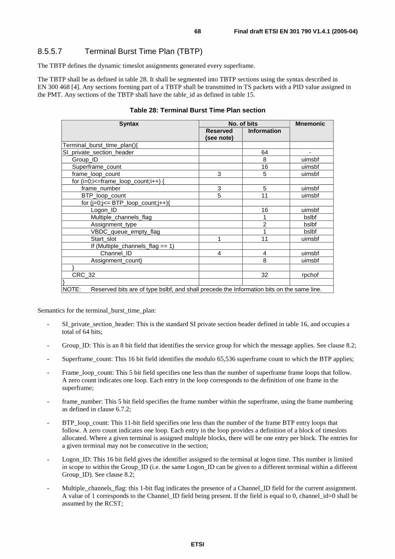
ETSI
Final draft ETSI EN 301 790 V1.4.1 (2005-04) 68
8.5.5.7 Terminal Burst Time Plan (TBTP)
The TBTP defines the dynamic timeslot assignments generated every superframe.
The TBTP shall be as defined in table 28. It shall be segmented into TBTP sections using the syntax described in EN 300 468 [4]. Any sections forming part of a TBTP shall be transmitted in TS packets with a PID value assigned in the PMT. Any sections of the TBTP shall have the table_id as defined in table 15.
Table 28: Terminal Burst Time Plan section
No. of bits Syntax Reserved (see note)
Information Mnemonic
Terminal_burst_time_plan(){ SI_private_section_header 64 - Group_ID 8 uimsbf Superframe_count 16 uimsbf frame_loop_count 3 5 uimsbf for (i=0;i<=frame_loop_count;i++) { frame_number 3 5 uimsbf BTP_loop_count 5 11 uimsbf for (j=0;j<= BTP_loop_count;j++){ Logon_ID 16 uimsbf Multiple_channels_flag 1 bslbf Assignment_type 2 bslbf VBDC_queue_empty_flag 1 bslbf Start_slot 1 11 uimsbf If (Multiple_channels_flag == 1) Channel_ID 4 4 uimsbf Assignment_count} 8 uimsbf } CRC_32 32 rpchof } NOTE: Reserved bits are of type bslbf, and shall precede the Information bits on the same line.
Semantics for the terminal_burst_time_plan:
- SI_private_section_header: This is the standard SI private section header defined in table 16, and occupies a total of 64 bits;
- Group_ID: This is an 8 bit field that identifies the service group for which the message applies. See clause 8.2;
- Superframe_count: This 16 bit field identifies the modulo 65,536 superframe count to which the BTP applies;
- Frame_loop_count: This 5 bit field specifies one less than the number of superframe frame loops that follow. A zero count indicates one loop. Each entry in the loop corresponds to the definition of one frame in the superframe;
- frame_number: This 5 bit field specifies the frame number within the superframe, using the frame numbering as defined in clause 6.7.2;
- BTP_loop_count: This 11-bit field specifies one less than the number of the frame BTP entry loops that follow. A zero count indicates one loop. Each entry in the loop provides a definition of a block of timeslots allocated. Where a given terminal is assigned multiple blocks, there will be one entry per block. The entries for a given terminal may not be consecutive in the section;
- Logon_ID: This 16 bit field gives the identifier assigned to the terminal at logon time. This number is limited in scope to within the Group_ID (i.e. the same Logon_ID can be given to a different terminal within a different Group_ID). See clause 8.2;
- Multiple_channels_flag: this 1-bit flag indicates the presence of a Channel_ID field for the current assignment. A value of 1 corresponds to the Channel_ID field being present. If the field is equal to 0, channel_id=0 shall be assumed by the RCST;

ETSI
Final draft ETSI EN 301 790 V1.4.1 (2005-04) 69
- Assignment_Type: This 2 bit field defines the repetitive nature of the assignment, as defined in table 29;
Table 29: Assign type
Assign type Value one time assignment 00 repeating assignment 01 assignment release 10 Reserved 11
VBDC_queue_empty_flag: This 1 bit flag is set to "1" when the VBDC queue for that RCST is empty after the assignments in the table, and is set to "0" when the VBDC queue is not empty. If the Multiple_channels_flag is set to "1", then the queue is that for the channel identified by the Channel_ID field.
- Start_slot: This 11 bit field gives the number of the first timeslot in the block, relative to the frame (numbering as defined in clause 6.7.2);
- Channel_ID: This 4-bit field indicates the channel to which timeslots are being assigned. Values are managed by the NCC. This field is present if the multiple_channels_flag is set to "1";
- Assignment_count: This 8 bit field gives one less than the number of timeslots assigned in the block. These timeslots will be consecutively numbered in ascending order starting with the start_slot;
- CRC_32: This is a 32 bit field that contains the CRC value that gives a zero output of the registers in the decoder defined in annex B of EN 300 468 [4] after processing the entire section.
8.5.5.8 Terminal Information Message (TIM)
The TIM is used to transmit static or quasi-static information about the forward and return links, such as configuration parameters. The format supports two variants of this message:
- a terminal specific (uni-cast) message containing information for a specific terminal. This variant may be encrypted for security reasons. It is sent during logon initialization, and when a parameter changes. When a TIM contains multiple descriptors, the terminal shall process all descriptors before changing its configuration;
- a broadcast message giving general information applicable to all terminals. This variant is unlikely to be encrypted. It will need to be transmitted sufficiently often that newly powered terminals can acquire any necessary information within a reasonable time. This matches a similar requirement for the SCT, FCT and TCT signals, suggesting the same repeat interval (see clause 8.3.5). It is recommended that the RCST is pre-programmed with suitable default values for parameters normally contained in the descriptors in the broadcast TIM, in particular those in the Contention Control Descriptor (see clause 8.5.5.10.14) and the Correction Control Descriptor (see clause 8.5.5.10.15). Selection of suitable default values will ordinarily be made by the manufacturer or network operator, prior to installation of the RCST. Values contained in the broadcast table shall override the defaults.

ETSI
Final draft ETSI EN 301 790 V1.4.1 (2005-04) 70
Table 30: Terminal Information Message section
No. of bits Syntax Reserved
(see note) Information Information Mnemonic
terminal_information_message_section() { DSM-CC_private_section_header 96 If MAC_address == RCST MAC (not broadcast) { RCST_Status } 8 flagmsf else { Network_status } 8 flagmsf descriptor_loop_count 8 uimsbf for (i= 0; i<= descriptor_loop_count; i++) { descriptor() } If MAC_address == RCST MAC (not broadcast) { Pad_bytes } see text bslbf CRC_32 32 rpchof } NOTE: Reserved bits are of type bslbf, and shall precede the Information bits on the same line. They
shall be ignored by the RCST. For an encrypted uni-cast TIM, the bit values shall be varied in a random manner to avoid encryption spoofing.
The TIM shall be as defined in table 30. It shall be segmented into terminal information message sections using the syntax described in EN 300 468 [4]. Any sections forming part of a TIM shall be transmitted in TS packets with a PID value assigned in the PMT. Any sections of the TIM shall have the table_id as described in table 15.
Semantics for the terminal_information_message_section:
- DSM-CC_private_section_header: This is the standard DSM-CC private section header defined in table 17, and occupies a total of 96 bits;
- RCST_Status: This 8 bit field gives status flags defining the network state of the RCST (see table 31);
Table 31: RCST status
Bit Identifier (MSB) 7 ID_encrypt
6 Logon_fail_(busy) 5 Logon_denied 4 Log_off 3 Transmit_Disable 2 Rain_Fade_release 1 Rain_Fade_detect
(LSB) 0 Wake_up
Semantics for the flag bits are as follows, where a logic "1" asserts the condition defined:
- ID_encrypt: Indicates that the terminal shall use TBTP logon ID encryption;
- Logon_fail_(busy): Indicates that the terminal cannot enter the network because of lack of resources;
- Logon_denied: Indicates that the terminal is not authorized to enter the network;
- Log_off: Indicates that the network has enforced a terminal logoff. The terminal shall immediately cease transmission and enter the logged off state;
- Transmit_Disable: Indicates that the terminal shall immediately cease transmission and enter the hold state, and shall not resume until it receives a uni-cast TIM with this bit reset to "0";
- Rain_Fade_release: Indicates that the NCC is performing a reconfiguration procedure to restore settings following cessation of a rain fade event;
- Rain_Fade_detect: Indicates that the NCC has detected a rain fade event and is performing a reconfiguration procedure to establish rain fade settings;

ETSI
Final draft ETSI EN 301 790 V1.4.1 (2005-04) 71
- Wake_up: indicates that the NCC wants to wake up the RCST;
- Network_Status: This 8 bit field gives status flags defining the network state for RCSTs within the scope of the broadcast MAC address. The flag bits shall be as defined in table 32.
Table 32: Network status
Bit Identifier (MSB) 7 ID_encrypt
6 Reserved 5 Reserved 4 CSC_link_failure_rec 3 Link_failure_recovery 2 Return_link_failure 1 NCC_Receive_Failure
(LSB) 0 Scheduler_Failure
Semantics for the flag bits are as follows, where a logic "1" asserts the condition defined:
- ID_encrypt: Indicates that terminals shall use TBTP logon ID encryption;
- CSC_link_failure_rec: Indicates that the system is recovering from a failure of a forward or return link. The NCC affects CSC bursts in the TBTP. Terminals shall wait for their reserved timeslot or use one of the CSC contention timeslots;
- Link_failure_recovery: Indicates that the system is recovering from a failure of a forward or return link. Terminals shall follow a pre-defined procedure for large outage recovery until a new broadcast TIM is received with this bit reset to "0";
- Return_link_failure: Indicates that the NCC has detected a failure of the return link. All RCSTs shall cease transmission until a new broadcast TIM is received with this bit reset to "0";
- NCC_Receive_Failure: Indicates that the NCC has a receive channel failure. Affected terminals shall suspend transmission until a new broadcast TIM is received indicating that the failure is no longer present;
- Scheduler_Failure: Indicates that the NCC has a scheduler failure. Affected terminals shall suspend transmission of all traffic, but not SYNC bursts, until a new broadcast TIM is received indicating that the failure is no longer present. SYNC bursts transmitted while the fault is present shall have the request field of the SAC set to "0";
- descriptor_loop_count: This 8 bit field defines one less than the number of descriptors in the following loop. A zero count indicates one loop;
- descriptor(): The descriptors that may be inserted into the TIM are defined in clause 8.5.5.10. It should be noted that the allowed descriptors are different between the unicast and broadcast versions of the TIM (as defined by the scope of the MAC address);
- Pad_bytes: Each Pad_byte shall be an 8 bit field. Sufficient Pad_bytes are inserted so as to pad the encrypted portion of the message to the encryption algorithm boundary. The content of these fields is undefined and shall be randomized to prevent code spoofing. The encrypted portion of the message starts immediately following the MAC Address fields and finishes immediately prior to the CRC_32 field;
- CRC_32: This is a 32 bit field that contains the CRC value that gives a zero output of the registers in the decoder defined in annex B of EN 300 468 [4] after processing the entire section.
8.5.5.9 Correction Message Table (CMT)
The CMT shall be as shown in table 33. It shall be segmented into terminal information message sections using the syntax described in EN 300 468 [4]. Any sections forming part of a CMT shall be transmitted in TS packets with a PID value assigned in the PMT. Any sections of the CMT shall have the table_id value as defined in table 15. This message provides closed loop feedback to a number of terminals to allow them to adjust the transmit power level, frequency and burst timing as required to maintain link integrity, as well as other error condition feedback messages.

ETSI
Final draft ETSI EN 301 790 V1.4.1 (2005-04) 72
Table 33: Correction Message Table section
No. of bits Syntax Reserved
(see note) Information Information Mnemonic
correction_message_table_section(){ SI_private_section_header 64 - Entry_loop_count 8 uimsbf for (i = 0;i <= Entry_loop_count; i++) { Group_ID 8 uimsbf Logon_ID 16 uimsbf Time_correction_flag 1 bslbf Power_correction_flag 1 bslbf Frequency_correction_flag 1 bslbf Slot_Type 2 bslbf Burst_time_scaling 3 uimsbf If (Time_correction_flag == 1) Burst_time_correction 8 tcimsbf If (Power_correction_flag == 1) Power_control_flag 1 bslbf If(Power_control_flag==1) Power_correction 7 tcimsbf else EsN0 7 tcimsbf If (Frequency_correction_flag == 1) Frequency_correction} 16 tcimsbf CRC_32 32 rpchof } NOTE: Reserved bits are of type bslbf, and shall precede the Information bits on the same line.
Semantics for the correction_message_table_section:
- SI_private_section_header: This is the standard SI private section header defined in table 16, and occupies a total of 64 bits;
- Entry_loop_count: This field specifies one less than the number of correction message loops that follow. A zero count indicates one loop;
- Group_ID: This 8 bit field defines which Group ID the RCST is assigned to, as identified by the Terminal Information Message (TIM). This matches the Group_ID used in the TBTP sections (see clause 8.5.5.7);
- Logon_ID: This 16 bit field identifies the assigned terminal logon identifier, as identified by the TIM. Nominally, this is the same as used in the TBTP sections. When scrambling is used, the Logon ID used in the CMT will be the unscrambled version, to avoid a possible compromise to the TBTP security;
- Time_correction_flag; Power_correction_flag; Frequency_correction_flag; Slot_type; Burst_time_scaling; Burst_time_correction; Power_control_flag; Power_correction; EsN0; Frequency_correction: These fields are identical to the matching fields of the Correction_message_descriptor, and define one measurement correction set. See clause 8.5.5.10.3 for a definition of the descriptor;
NOTE: The CMT does not use the descriptor directly, since the added descriptor_tag and descriptor_length parameters would represent a substantial, and unnecessary, overhead.
- CRC_32: This is a 32 bit field that contains the CRC value that gives a zero output of the registers in the decoder defined in annex B of EN 300 468 [4] after processing the entire section.

ETSI
Final draft ETSI EN 301 790 V1.4.1 (2005-04) 73
8.5.5.10 Descriptor coding
8.5.5.10.1 Descriptor identification and location
Table 34 lists the descriptors defined within the present document, giving the descriptor-tag values and the intended placement within the tables.
Table 34: Descriptor tags and locations
PMT RMT TIM (see note 1) descriptor Tag
value Broadcast Unicast Network_layer_info_descriptor 0xA0 X Correction_message_descriptor 0xA1 X Logon_initialize_descriptor 0xA2 X ACQ_assign_descriptor 0xA3 X SYNC_assign_descriptor 0xA4 X Encrypted_Logon_ID_descriptor 0xA5 X Echo_value_descriptor 0xA6 X X Linkage_descriptor (private data) (see note 2) 0x4A X RCS_content_descriptor 0xA7 X Satellite_forward_link_descriptor 0xA8 X X Satellite_return_link_descriptor 0xA9 X X table_update_descriptor 0xAA X Contention_control_descriptor 0xAB X Correction_control_descriptor 0xAC X Forward_interaction_path_descriptor 0xAD X Return_interaction_path_descriptor 0xAE X Connection_control_descriptor 0xAF X NOTE 1: For the TIM message sections, the definition of intended placement differs between the unicast
and broadcast versions of that message. NOTE 2: Private extension to existing DVB descriptor.
After logon, the unicast TIM contains at least the following descriptors: Correction_message_descriptor, Logon_initialize_descriptor, SYNC_assign_descriptor and Satellite_return_link_descriptor.
8.5.5.10.2 Network Layer Info descriptor (optional)
The Network Layer Info descriptor provides a mechanism by which network level information, such as the meta-signalling VPI/VCI and base IP address, can be passed to the Management Plane of the RCST during, or prior to, the start-up configuration phase of logon. As such, the message content is passed transparently through the lower layers covered by the present document and is not defined here. The descriptor is defined in table 35.
Table 35: Network Layer Info descriptor
Syntax No. of bits Mnemonic Network_layer_info_descriptor(){ descriptor_tag 8 uimsbf descriptor_length 8 uimsbf Message_body see text }

ETSI
Final draft ETSI EN 301 790 V1.4.1 (2005-04) 74
Semantics for the Network_layer_info_descriptor:
- descriptor_tag: The descriptor tag is an 8 bit field which identifies each descriptor. Its value is given in the Tag value column of table 34;
- descriptor_length: The descriptor length is an 8 bit field specifying the number of bytes of the descriptor immediately following the descriptor_length field;
- Message_body: This variable length field shall contain a datagram for passing to the target application. The length of the message body shall not exceed 255 bytes, and should preferably be limited such that the section containing this descriptor fits within a single TS packet. This datagram will take the form of an SNMP message. The messages that can be passed by this method are beyond the scope of the present document. Basic functionalities related with the network are provided with the logon initialize descriptor (see clause 8.5.5.10.4). This descriptor is optional, the RCST indicates in the CSC burst (see clause 6.2.3) if it implements SNMP.
8.5.5.10.3 Correction Message descriptor
The Correction Message descriptor defines a transmit parameter correction set for one terminal measurement. It shall be as defined in table 36.
Table 36: Correction Message descriptor
No. of bits Syntax Reserved
(see note) Information Information Mnemonic
Correction_message_descriptor(){ descriptor_tag 8 uimsbf descriptor_length 8 uimsbf Time_correction_flag 1 bslbf Power_correction_flag 1 bslbf Frequency_correction_flag 1 bslbf Slot_Type 2 bslbf Burst_time_scaling 3 uimsbf If (Time_correction_flag == 1) Burst_time_correction 8 tcimsbf If (Power_correction_flag == 1) Power_control_flag 1 bslbf If(Power_control_flag==1) Power_correction 7 tcimsbf else EsN0 7 tcimsbf If (Frequency_correction_flag == 1) Frequency_correction 16 tcimsbf } NOTE: Reserved bits are of type bslbf, and shall precede the Information bits on the same line. For
encrypted message types, the value of these bits is undefined.
Semantics for the Correction_message_descriptor:
- descriptor_tag: The descriptor tag is an 8 bit field which identifies each descriptor. Its value is given in the Tag value column of table 34;
- descriptor_length: The descriptor length is an 8 bit field specifying the number of bytes of the descriptor immediately following the descriptor_length field;
- Time_correction_flag, Power_correction_flag, Frequency_correction_flag: these three bits are used to indicated the presence of time, power and frequency correction fields, respectively, in the remainder of the descriptor;

ETSI
Final draft ETSI EN 301 790 V1.4.1 (2005-04) 75
- Slot_type: This 2 bit field identifies the type of burst being measured, as defined in table 37;
Table 37: Slot type
Value Identifier 00 TRF 01 CSC 10 ACQ 11 SYNC
- Burst_time_scaling: This 3 bit field gives the power-of-2 scaling to apply to the Burst_time_correction parameter, i.e. a value of 2 indicates a scaling factor of 4 (= shift left 2 bits). In case there is no time correction in this descriptor, i.e. the Time_correction_flag is equal to 0, the Burst_time_scaling field shall be set to 000;
- Burst_time_correction: This 8 bit field gives the required correction to burst timing as a two's complement binary PCR clock count (i.e. in counts of the 27 MHz PCR clock) that shall be scaled according to the Burst_time_scaling field above. To minimize truncation errors, the N LSB bits of the scaled value shall be set to an approximate mid-range value of "1" followed by "0"s, with N being the value of the Burst_time_scaling field. For example, with N = 2, the resulting clock count value is "dd dddd dd10";
- Power_control_flag: This 1 bit field defines how uplink power control for the return link is carried out. The value "1"indicates that the NCC transmits a power correction value for the RCST and the value "0" indicates that the NCC transmits a measured Es/N0 value instead;
- Power_correction: This 7 bit field gives the required correction to uplink power on the return link in 0,5 dB steps as a two's complement integer value;
- EsN0: This 7 bit field gives the measured Es/N0 value on the return link in 0,5 dB steps as two's complement
integer value. This value can be used to control the uplink power, as an alternative to the Power_correction value. Es/N0 is the energy per transmitted symbol, divided by the spectral density of noise and interference.;
- Frequency_correction: This 16 bit field gives the required correction to frequency in 10 Hz steps, as a two's complement integer value. A negative value indicates that the terminal shall reduce frequency. For systems not implementing frequency correction, this field shall be set to all 0's.

ETSI
Final draft ETSI EN 301 790 V1.4.1 (2005-04) 76
8.5.5.10.4 Logon Initialize descriptor
This descriptor provides parameters needed for initial logon (see table 38).
Table 38: Logon Initialize descriptor
No. of bits Syntax Reserved
(see note) Information Information Mnemonic
Logon_Initialize_descriptor() { descriptor_tag 8 uimsbf descriptor_length 8 uimsbf Group_ID 8 uimsbf Logon_ID 16 uimsbf Security_handshake_required 3 1 bslbf Prefix _flag 1 bslbf Data_unit_labelling_flag 1 bslbf Mini_slot_flag 1 bslbf Contention_based_mini_slot_flag 1 bslbf Capacity_type_flag 1 1 bslbf Traffic_burst_type 1 bslbf If (Traffic_burst_type == 0) { Connectivity 1 bslbf If (Connectivity == 0) { Return_VPI 4 8 uimsbf Return_VCI 16 uimsbf } Else { Return_signalling_VPI 4 8 uimsbf Return_ signalling_VCI 16 uimsbf Forward_ signalling_VPI 8 8 uimsbf Forward_ signalling_VCI 16 uimsbf } } Else { Return_TRF_PID 13 uimsbf Return_CTRL_MNGM_PID 3 13 uimsbf } if (Capacity_type_flag == 0) { CRA_level 24 uimsbf VBDC_max 5 11 uimsbf RBDC_max 24 uimsbf RBDC_timeout 16 uimsbf } } NOTE: Reserved bits are of type bslbf, and shall precede the Information bits on the same line. They
shall be ignored by the RCST. For an encrypted uni-cast TIM, the bit values shall be varied in a random manner to avoid encryption spoofing.
Semantics for the Logon_initialize_descriptor:
- descriptor_tag: The descriptor tag is an 8 bit field which identifies each descriptor. Its value is given in the Tag value column of table 34;
- descriptor_length: The descriptor length is an 8 bit field specifying the number of bytes of the descriptor immediately following the descriptor_length field;
- Group_ID: This 8 bit field defines which Group ID the terminal is assigned to. This matches the Group_ID used in the TBTP and CMT sections;
- Logon_ID: This 16 bit field identifies the assigned terminal logon identifier, which is used in the TBTP and CMT sections;
- Security_handshake_required: the value "1" indicates that the security handshake as described in clause 9.4 is to be used. Otherwise it is set to "0";

ETSI
Final draft ETSI EN 301 790 V1.4.1 (2005-04) 77
- Prefix_flag: The value "1" indicates that the Prefix Method according to clause 6.6.1.2 is implemented in the network and the value "0" indicates that it is not implemented;
- Data_unit_labelling_flag: The value "1" indicates that the Data Unit Labelling Method according to clause 6.6.2 is implemented in the network and the value "0" indicates that it is not implemented;
- Mini_slot_flag: The value "1" indicates that the Mini-slot Method according to clause 6.6.1.3 is implemented in the network and the value "0" indicates that it is not implemented;
- Contention_based_mini_slot_flag: The value "1" indicates that the Contention-based Mini-slot Method according to clause 6.6.1.4 is implemented in the network and the value "0" indicates that it is not implemented;
- Capacity_type_flag: A value of "0" indicates that fields defining settings and limits for capacity requests are present. A value of "1" indicates that these fields are absent;
- Traffic_burst_type: This 1 bit field defines the traffic burst type to be used on the return link. The value "0" indicates ATM TRF according to clause 6.2.1.1 and the value "1" indicates optional MPEG2-TS TRF according to clause 6.2.1.2;
- Connectivity: This 1 bit field defines the connectivity to be used. The value "0" indicates IP connectivity according to clause 8.1.1 (Type A RCST) and the value "1" indicates optional ATM connectivity according to clause 8.1.2 (Type B RCST). In the case of MPEG2-TS TRF the connectivity is always IP and therefore not signalled;
- Return_VPI, Return_VCI: These fields define the VPI/VCI that the RCST shall use in ATM cells on the return link;
- Return_signalling_VPI, Return_signalling_VCI: These fields define the VPI/VCI that is used on the return link for ITU-T Recommendation Q.2931 [11] signalling instead of the normal value 0/5. The signalling is used to set up connections for traffic. These parameters can be the same for all RCSTs;
- Forward_signalling_VPI, Forward_signalling_VCI: These fields define the VPI/VCI that is used on the forward link for ITU-T Recommendation Q.2931 [11] signalling instead of the normal values 0/5. The signalling is used to set up connections for traffic;
- Return_TRF_PID: This 13 bit field defines the PID that the RCST shall use in optional MPEG2 TS packets on the return link for traffic information. This parameter can be the same for all RCSTs;
- Return_CTRL_MNGM_PID: This 13 bit field defines the PID that the RCST shall use in optional MPEG2 TS packets on the return link for CTRL/MNGM information. This parameter can be the same for all RCSTs.
- CRA_level: The CRA assignment to the terminal, in bits/s;
- VBDC_max: The maximum allowed number of VBDC time slots per frame;
- RBDC_max: The maximum allowed RBDC data rate, in bits/s;
- RBDC_timeout: The RBDC timeout, in superframes. A value of "0" indicates that the timeout is disabled.

ETSI
Final draft ETSI EN 301 790 V1.4.1 (2005-04) 78
8.5.5.10.5 ACQ Assign descriptor
This descriptor (table 39) defines the assignment of Acquisition bursts for the optional coarse synchronization procedure at logon. If used, it will only be present following detection of a valid CSC from the terminal. Some systems may choose to assign acquisition timeslots via the TBTP instead of using this descriptor.
Table 39: ACQ Assign descriptor
No. of bits Syntax Reserved
(see note) Information Information Mnemonic
ACQ_assign_descriptor() { descriptor_tag 8 uimsbf descriptor_length 8 uimsbf ACQ_achieved_time_threshold 8 uimsbf ACQ_achieved_frequency_threshold 16 uimsbf ACQ_repeats 2 6 uimsbf ACQ_start_superframe 16 uimsbf ACQ_frame_number 3 5 uimsbf ACQ_repeat_period 2 6 uimsbf ACQ_slot_number 5 11 uimsbf } NOTE: Reserved bits are of type bslbf, and shall precede the Information bits on the same line. They shall
be ignored by the RCST. For an encrypted uni-cast TIM, the bit values shall be varied in a random manner to avoid encryption spoofing.
Semantics for the ACQ_assign_descriptor:
- descriptor_tag: The descriptor tag is an 8 bit field which identifies each descriptor. Its value is given in the Tag value column of table 34;
- descriptor_length: The descriptor length is an 8 bit field specifying the number of bytes of the descriptor immediately following the descriptor_length field;
- ACQ_achieved_time_threshold: This 8 bit field gives the magnitude of the burst timing error threshold value to be used for the transition from the coarse synchronization procedure to the "ready for fine sync" state, see clause 7.1. The value is scaled by the same amount as the Burst_time_correction value of the Correction Message Table and Correction Message descriptor, allowing a direct magnitude comparison with that value. Transition to the "ready for fine sync" state occurs when the magnitude of the measured Burst_time_correction value is less than, or equal to, the ACQ_achieved_time_threshold;
- ACQ_achieved_frequency_threshold: This 16 bit field gives the magnitude of the carrier frequency error threshold value to be used for the transition from the coarse synchronization procedure to "ready for fine sync" state, see clause 7.1. Transition to the "ready for fine sync" state occurs when the magnitude of the measured Frequency_correction value is less than, or equal to, the ACQ_achieved_frequency_threshold;
NOTE: If both ACQ_achieved_time_threshold and ACQ_achieved_frequency_threshold have non-zero values, transition to the "ready for fine sync" state occurs when both criterion are fulfilled.
- ACQ_repeats: This 6 bit field defines the maximum number of times that the ACQ shall be repeated during the Coarse Synchronization procedure. A special value of "00 0000" is reserved to indicate that the terminal is being given a sustained acquisition burst. This special value is reserved for use during terminal alignment procedures, typically at the time of installation;
- ACQ_start_superframe: This 16 bit field gives the modulo 65536 superframe number at which the ACQ assignment starts (see SCT Superframe_counter parameter in clause 8.5.5.2);
- ACQ_frame_number: This 5 bit field identifies which frame number in the superframe contains the ACQ burst. This number matches the frame numbering defined in clause 6.7.2;
- ACQ_repeat_period: This 6 bit field gives the number of superframes between ACQ repeats;
- ACQ_slot_number: This 11 bit field identifies the timeslot number to use for ACQ. This number matches the numbering defined in clause 6.7.2.

ETSI
Final draft ETSI EN 301 790 V1.4.1 (2005-04) 79
8.5.5.10.6 SYNC Assign descriptor
This descriptor (table 40) provides the static BTP assignment of SYNC bursts. It is typically sent following the detection of a valid CSC from the terminal, but may also be sent when it is necessary to modify the SYNC assignment.
Table 40: SYNC Assign descriptor
No. of bits Syntax Reserved
(see note) Information Information Mnemonic
SYNC_assign_descriptor() { descriptor_tag 8 uimsbf descriptor_length 8 uimsbf SYNC_achieved_time_threshold 8 uimsbf max_SYNC_tries 8 uimsbf SYNC_achieved_frequency_threshold 16 uimsbf SYNC_start_superframe 16 uimsbf SYNC_frame_number 3 5 uimsbf SYNC_repeat_period 16 uimsbf SYNC_slot_number 5 11 uimsbf } NOTE: Reserved bits are of type bslbf, and shall precede the Information bits on the same line. They
shall be ignored by the RCST. For an encrypted uni-cast TIM, the bit values shall be varied in a random manner to avoid encryption spoofing.
Semantics for the SYNC_assign_descriptor:
- descriptor_tag: The descriptor tag is an 8 bit field which identifies each descriptor. Its value is given in the Tag value column of table 34;
- descriptor_length: The descriptor length is an 8 bit field specifying the number of bytes of the descriptor immediately following the descriptor_length field;
- SYNC_achieved_time_threshold: This 8 bit field gives the magnitude of the burst timing error threshold value to be used for the transition from the fine synchronization procedure to the "fine sync" state, see clause 7.1. The value is scaled by the same amount as the Burst_time_correction value of the Correction Message Table and Correction Message descriptor, allowing a direct magnitude comparison with that value. Transition to the "fine sync" state occurs when the magnitude of the measured Burst_time_correction value is less than, or equal to, the SYNC_achieved_time_threshold;
- max_SYNC_tries: This 8 bit field gives the maximum number of bursts that the RCST can send to achieve fine synchronization, from the start of the "ready for fine sync" state (see clause 7.1);
- SYNC_achieved_frequency_threshold: This 16 bit field gives the magnitude of the carrier frequency error threshold value to be used for the transition from the fine synchronization procedure to the "fine sync" state, see clause 7.1. Transition to the "fine sync" state occurs when the magnitude of the measured Frequency_correction value is less than, or equal to, the SYNC_achieved_frequency_threshold;
NOTE: If both SYNC_achieved_time_threshold and SYNC_achieved_frequency_threshold have non-zero values, transition to the "fine sync" state occurs when both criterion are fulfilled.
- SYNC_start_superframe: This 16 bit field gives the modulo 65536 superframe number at which the SYNC assignment starts (see SCT Superframe_counter parameter in clause 8.5.5.2);
- SYNC_frame_number: This 5 bit field identifies which frame number in the superframe contains the SYNC burst. This number matches the frame numbering defined in clause 6.7.2;
- SYNC_repeat_period: This 16 bit field gives the number of superframes between SYNC repeats, for example, SYNC_repeat_period=0 means that the SYNC slot is assigned on each superframe, SYNC_repeat_period=1 means that two superframes containing the SYNC slot assignment are separated by 1 superframe that does not have the SYNC slot assigned, and so on;
- SYNC_slot_number: This 11 bit field identifies the timeslot number to use for SYNC. This number matches the numbering defined in clause 6.7.2.

ETSI
Final draft ETSI EN 301 790 V1.4.1 (2005-04) 80
8.5.5.10.7 Encrypted Logon ID descriptor
This descriptor (see table 41) is provided as one possible method of TBTP key management, when the TBTP is encrypted. It requires that the TIM message itself be encrypted with an RCST specific key.
Table 41: Encrypted Logon ID descriptor
No. of bits Syntax Reserved
(see note) Information Information Mnemonic
Encrypted_Logon_ID_descriptor() { descriptor_tag 8 uimsbf descriptor_length 8 uimsbf ID_start_time 16 uimsbf ID_update_period 16 uimsbf ID_loop_count 8 uimsbf for (i = 0; i<= ID_loop_count; i++) { Encrypted_Logon_ID } 16 uimsbf } NOTE: Reserved bits are of type bslbf, and shall precede the Information bits on the same line. They
shall be ignored by the RCST. The value of these bits is undefined and shall be varied in a random manner to avoid encryption spoofing.
Semantics for the Encrypted_Logon_ID_descriptor:
- descriptor_tag: The descriptor tag is an 8 bit field which identifies each descriptor. Its value is given in the Tag value column of table 34;
- descriptor_length: The descriptor length is an 8 bit field specifying the number of bytes of the descriptor immediately following the descriptor_length field;
- ID_Start_time: This 16 bit field gives the superframe count value at which the first Encrypted_Logon_ID parameter in the following loop takes effect. This corresponds to the superframe counter defined in the SCT and TBTP;
- ID_update_period: This 16 bit field gives the period, in terms of superframe counts, at which successive Encrypted_Logon_ID parameters take effect following the first such parameter;
- ID_loop_count: This 8 bit field defines one less than the number of encrypted logon ID's that follow. A zero count indicates one loop. The ID's follow in sequential time order, earliest first;
- Encrypted_Logon_ID: This 16 bit value gives the value for a future encrypted logon ID.
8.5.5.10.8 Echo Value descriptor
This descriptor (table 42) supports a simple loop-back RCST diagnostic test.
Table 42: Echo Value descriptor
No. of bits Syntax Reserved
(see note) Information Information Mnemonic
Echo_value_descriptor() { descriptor_tag 8 uimsbf descriptor_length 8 uimsbf Echo_Value 16 "1" + bslbf } NOTE: Reserved bits are of type bslbf, and shall precede the Information bits on the same line. They
shall be ignored by the RCST. For an encrypted uni-cast TIM, the bit values shall be varied in a random manner to avoid encryption spoofing.

ETSI
Final draft ETSI EN 301 790 V1.4.1 (2005-04) 81
Semantics for the Echo_value_descriptor:
- descriptor_tag: The descriptor tag is an 8 bit field which identifies each descriptor. Its value is given in the Tag value column of table 34;
- descriptor_length: The descriptor length is an 8 bit field specifying the number of bytes of the descriptor immediately following the descriptor_length field;
- Echo_value: This 16 bit field defines the value to be echoed back (for example in the 2 M&C bytes of the return link SAC field). The MSB shall be set to "1".
8.5.5.10.9 Linkage descriptor (private data)
This is an extension to the standard DVB Linkage descriptor (see EN 300 468 [4], clause 6.2.11), occupying the private data bytes provision at the end of that descriptor. It allows the RCST to identify which interactive network services its population group. The Linkage descriptor shall be as EN 300 468 [4], table 47, with the changes as highlighted in bold font in table 43.
Table 43: Linkage descriptor - private data
No. of bits Syntax Reserved
(see note) Information Information Mnemonic
linkage_descriptor(){ descriptor_tag 8 uimsbf descriptor_length 8 uimsbf transport_stream_id 16 uimsbf original_network_id 16 uimsbf service_id 16 uimsbf linkage_type 8 uimsbf Interactive_Network_ID 16 uimsbf Population_ID_loop_count 8 uimsbf for (i=0; i<=Population_ID_loop_count; i++) { population_ID_base 16 uimsbf population_ID_mask 16 uimsbf } for (i=0;i<N;i++) { private_data_byte 8 bslbf } } NOTE: Reserved bits are of type bslbf, and shall precede the Information bits on the same line. They
shall be ignored by the RCST. For an encrypted uni-cast TIM, the bit values shall be varied in a random manner to avoid encryption spoofing.
Semantics for the private data part of the linkage_descriptor:
- descriptor_tag: The descriptor tag is an 8 bit field which identifies each descriptor. Its value is defined in EN 300 468 [4] and is recalled in table 34;
- descriptor_length: The descriptor length is an 8 bit field specifying the number of bytes of the descriptor immediately following the descriptor_length field;
- transport_stream_id: This is a 16-bit field which identifies the TS containing the information service indicated;
- original_network_id: This 16-bit field gives the label identifying the network_id of the originating delivery system of the information service indicated;
- service_id: This is a 16-bit field which uniquely identifies an information service within a TS. The service_id is the same as the program_number in the corresponding program_map section;
- linkage_type: This is an 8-bit field specifying the type of linkage. Its value is 0x81 for "RCS FLS";
- Interactive_Network_ID: This 16 bit field gives the label identifying the network_ID for the interactive network that services the population_ID's following;

ETSI
Final draft ETSI EN 301 790 V1.4.1 (2005-04) 82
- Population_ID_loop_count: This 8 bit field indicates one less than the number of population_ID ranges in the following list;
- population_ID_base and population_ID_mask: These two 16 bit values, in combination, define a range of population_ID's associated with this linkage descriptor/interactive network. The population_ID is the identifier for the population group that the RCST belongs to. This is a value assigned by the network operator, and is a configuration parameter known to the RCST prior to forward link acquisition. The population_ID_base parameter defines the fixed bit pattern part of the population_ID range, while the population_ID_mask parameter defines those bit positions of the population ID that are "not significant". A "1" value in a bit of the mask indicates that the corresponding bit of the RCST population_ID may be "1" or "0". A "0" value in a bit of the mask indicates that the corresponding bit of the RCST population_ID shall match the value of that bit in the base parameter;
- private_data_byte: This is an 8 bit field, the value of which is privately defined. It retains the functionality of the original linkage_descriptor for further extensions.
8.5.5.10.10 RCS content descriptor
The RCS content descriptor provides the definition of the PID assignments to the RCS specific tables, and is shown in table 44. This descriptor is used in the second loop of the Program Map Table (PMT), defined in ISO/IEC 13818-1 [9], clause 2.4.4.8/table 2-28. Each descriptor defines the General RCS SI Tables and RCS Specific Messages associated with one elementary_PID.
The use of the RCS content descriptor for the RMT is optional.
NOTE: The PCR Insertion packet PID is signalled earlier in the PMT section as the PCR_PID parameter.
Table 44: RCS content descriptor
No. of bits Syntax Reserved
(see note) Information Information Mnemonic
RCS_content_descriptor() { descriptor_tag 8 uimsbf descriptor_length 8 uimsbf for (i=0; i<N; i++) { Table_id 8 uimsbf } } NOTE: Reserved bits are of type bslbf, and shall precede the Information bits on the same line. They
shall be ignored by the RCST. For an encrypted uni-cast TIM, the bit values shall be varied in a random manner to avoid encryption spoofing.
Semantics for the RCS_content_descriptor:
- descriptor_tag: The descriptor tag is an 8 bit field which identifies each descriptor. Its value is given in the Tag value column of table 34;
- descriptor_length: The descriptor length is an 8 bit field specifying the number of bytes of the descriptor immediately following the descriptor_length field;
- table_id: This 8 bit field gives the table_id value for a General RCS SI Table or RCS Specific Message, as defined in table 15.

ETSI
Final draft ETSI EN 301 790 V1.4.1 (2005-04) 83
8.5.5.10.11 Satellite forward link descriptor
The satellite forward link descriptor defines the forward link, and is used in place of the Satellite delivery system descriptor of EN 300 468 [4] for RCS systems. It is shown in table 45.
Table 45: Satellite forward link descriptor
No. of bits Syntax Reserved
(see note) Information Information Mnemonic
Satellite_forward_link_descriptor() { descriptor_tag 8 uimsbf descriptor_length 8 uimsbf satellite_ID 8 uimsbf beam_ID 16 uimsbf NCC_ID 8 uimsbf link_usage 3 bslbf local_link_ID 5 uimsbf frequency 32 uimsbf orbital_position 16 bslbf west_east_flag 1 bslbf Polarization 2 bslbf transmission_standard 2 uimsbf if (transmission_standard == 0) { "001" 3 bslbf } else if ((transmission_standard == 1) or (transmission_standard == 2)) {
scrambling sequence selector 1 bslbf roll_off 2 uimsbf } symbol_rate 24 uimsbf if (transmission_standard == 0){ FEC_inner 4 bslbf Reserved 4 bslbf } else if ((transmission_standard == 1) or (transmission_standard == 2)) {
Input_Stream_Identifier 8 uimsbf if (scrambling_sequence_selector == 0) scrambling_sequence_index 6 18 uimsbf } for (i=0; i<N; i++) { private_data_byte 8 bslbf } } NOTE: Reserved bits are of type bslbf, and shall precede the Information bits on the same line. They
shall be ignored by the RCST. For an encrypted uni-cast TIM, the bit values shall be varied in a random manner to avoid encryption spoofing.
Semantics for the Satellite_forward_link_descriptor:
- descriptor_tag: The descriptor tag is an 8 bit field which identifies each descriptor. Its value is given in the Tag value column of table 34;
- descriptor_length: The descriptor length is an 8 bit field specifying the number of bytes of the descriptor immediately following the descriptor_length field;
- satellite_ID: This 8 bit field identifies which satellite is carrying the forward link, and corresponds to the satellite_ID field in the SPT/PCR Insertion packet payload;
- beam_ID: This 16 bit field identifies the beam number of the satellite carrying the forward link;
- NCC_ID: This 8 bit field identifies which NCC is transmitting the forward link, and corresponds to the NCC_ID field in the PCR Insertion packet payload (see clause 8.5.5.6);

ETSI
Final draft ETSI EN 301 790 V1.4.1 (2005-04) 84
- link_usage: This 3 bit field allows link discrimination for RCSTs that can operate on multiple forward links simultaneously. The usage codes are shown in table 46.
Table 46: Forward link usage codes
Usage code Value 000 Combined signalling/data link 001 Signalling link only 010 Data link only 111 Release data link 011 to 110 Reserved for future use
The first two codes are mutually exclusive in any Transport Stream ID (TS_id) entry of the RMT (there can be only one signalling link for a given population_ID). The signalling link only value can only be used where all RCSTs covered by that TS_id are capable of receiving multiple forward links simultaneously.
The release data link value allows a previously assigned data link to be released, without logging off the terminal.
For RCSTs that can operate on multiple forward links simultaneously, there are two possible modes of defining links during logon:
- the RMT defines only the signalling link, and the TIM defines any data only links. This is the most flexible method;
- the RMT uses multiple descriptors, one for each forward link defined. Only one of these may be a signalling link.
NOTE 1: In DVB terms, this mode "stretches" the definition of a transport stream to actually cover a group of inter-related transport streams.
For both modes, the TIM can command changes to the initial configuration defined via the RMT.
NOTE 2: Changing a signalling link may cause service interruption and is not recommended.
RCSTs capable only of single carrier operation shall use only the combined signalling/data link descriptor and shall ignore descriptors for other link_usage codes.
- local_link_ID: This 5 bit field is used to simplify changes to the definition of a link for RCSTs that can operate on multiple forward links simultaneously, and is a RCS local value defined by the interactive network operator. It allows the NCC to indicate which of the forward links is being created, changed or released. The last two operations can only be performed via a TIM message;
- frequency: This 32-bit field gives the frequency value. The frequency is given in multiples of 100 Hz;
- orbital_position: The orbital_position is a 16 bit field giving the 4-bit BCD values specifying 4 characters of the orbital position in degrees where the decimal point is after the third character (e.g. 019,2°);
- west_east_flag: The west_east_flag is a 1 bit field indicating if the satellite position is in the western or eastern part of the orbit. A value "0" indicates the western position and a value "1" indicates the eastern position;
- polarization: The polarization is a 2 bit field specifying the polarization of the transmitted signal (see table 47);
Table 47: Forward link polarization
Polarization Value linear - horizontal 00 linear - vertical 01 circular - left 10 circular - right 11
- transmission_standard: 0 for DVB-S, 1 for DVB-S2 using CCM, 2 for DVB-S2 using ACM and 3 reserved;
- scrambling sequence selector: value 1 means default DVB-S2 physical layer scrambling sequence of index 0, value 0 means that the scrambling sequence to be used is specified using the scrambling_sequence_index field;

ETSI
Final draft ETSI EN 301 790 V1.4.1 (2005-04) 85
- roll_off: 0 for not defined, 1 for 20 %, 2 for 25 %, 3 for 35 %;
- symbol_rate: The symbol_rate is a 24 bit field giving the symbol rate in multiples of 100 symbols/s;
- FEC_inner: The FEC_inner is a 4 bit field specifying the inner FEC scheme used, as per table 48.
Table 48: Inner FEC scheme
Code Rate Value 1/2 0000 2/3 0001 3/4 0010 5/6 0011 7/8 0100 Inner code is omitted 1111 Reserved for future use 0101 to 1110
- Input_Stream_Identifier: as defined in clause 5.1.6 of [19];
- scrambling_sequence_index: DVB-S2 physical layer scrambling sequence index as defined in clause 5.5.4 of [19];
- private_data_byte: This is an 8 bit field, the value of which is privately defined. It can be used, for example, to indicate system specific NCC information.
8.5.5.10.12 Satellite return link descriptor
Table 49: Satellite return link descriptor
No. of bits Syntax Reserved
(see note) Information Information Mnemonic
Satellite_return_link_descriptor() { descriptor_tag 8 uimsbf descriptor_length 8 uimsbf satellite_ID 8 uimsbf beam_ID 16 uimsbf gateway_ID 8 uimsbf Reserved 8 bslbf orbital_position 16 bslbf west_east_flag 7 1 bslbf Superframe_ID 8 uimsbf Tx_frequency_offset 24 tcimsbf for (i=0; i<N; i++) { private_data_byte 8 bslbf } } NOTE: Reserved bits are of type bslbf, and shall precede the Information bits on the same line. They
shall be ignored by the RCST. For an encrypted uni-cast TIM, the bit values shall be varied in a random manner to avoid encryption spoofing.
The satellite return link descriptor defines the characteristics of the return link and is shown in table 49.
Semantics for the Satellite_return_link_descriptor:
- descriptor_tag: The descriptor tag is an 8 bit field which identifies each descriptor. Its value is given in the Tag value column of table 34;
- descriptor_length: The descriptor length is an 8 bit field specifying the number of bytes of the descriptor immediately following the descriptor_length field;
- satellite_ID: This 8 bit field identifies which satellite is carrying the return link, and corresponds to the satellite_ID field in the SPT/PCR Insertion packet payload;

ETSI
Final draft ETSI EN 301 790 V1.4.1 (2005-04) 86
- beam_ID: This 16 bit field identifies the beam number of the satellite carrying the return link;
- gateway_ID: This 8 bit field identifies which Gateway is receiving the return link, and corresponds to the gateway_ID field in the PCR Insertion packet payload;
- orbital_position: The orbital_position is a 16 bit field giving the 4-bit BCD values specifying 4 characters of the orbital position in degrees where the decimal point is after the third character (e.g. 019,2°);
- west_east_flag: The west_east_flag is a 1 bit field indicating if the satellite position is in the western or eastern part of the orbit. A value "0" indicates the western position and a value "1" indicates the eastern position;
- superframe_ID: This 8 bit field identifies which superframe the terminal is to use. This identifier matches an entry in the SCT;
- Tx_frequency_offset: This 24-bit field gives the signed offset of the RCST transmit centre frequency relative to the Superframe_centre_frequency parameter (SCT). The frequency is given in multiples of 100 Hz. This parameter shall be ignored by the RCSTs when it is used in broadcast messages;
- private_data_byte: This is an 8 bit field, the value of which is privately defined. It can be used, for example, to indicate system specific NCC information.
8.5.5.10.13 Table Update descriptor
The Table Update descriptor (see table 50) provides a mechanism for notifying RCSTs when there is an upcoming change to one of the RCS Tables. In normal operation, these tables are expected to change infrequently. This descriptor provides a method for notifying the RCSTs on a particular interactive network when an update to one or more of these tables is imminent. This allows the RCSTs to only scan for table changes at this time, so freeing up processing resources. An RCST that monitors the composition tables continually may ignore this descriptor. Use of this descriptor does not modify the normal update control method implemented by the version_number and current_next_indicator fields of the section header. In addition, the Table Update descriptor may be utilized to indicate an update to any General SI Table defined in the present document or DVB-SI table, such as NIT, BAT, SDT, EIT, etc.
NOTE: In the case of the SCT, the Superframe start time (parameters Superframe_start_time_base and Superframe_start_time_ext) for each superframe definition, changes in a systematic fashion to reflect the regular period of the superframe. No update will be signalled where this is the only change and where the change has no material effect on superframe timing (i.e. the new start time equals a previous start time plus an integer number of superframe periods for the superframe in question).
Table 50: Table Update descriptor
No. of bits Syntax Reserved
(see note) Information Information Mnemonic
table_update_descriptor() { descriptor_tag 8 uimsbf descriptor_length 8 uimsbf interactive_network_id 16 uimsbf for (i=0; i<n; i++) { table_id 8 uimsbf new_version 3 5 uimsbf } } NOTE: Reserved bits are of type bslbf, and shall precede the Information bits on the same line. They
shall be ignored by the RCST. For an encrypted uni-cast TIM, the bit values shall be varied in a random manner to avoid encryption spoofing.
Semantics for the table_update_descriptor:
- descriptor_tag: The descriptor tag is an 8 bit field which identifies each descriptor. Its value is given in the Tag value column of table 34;
- descriptor_length: The descriptor length is an 8 bit field specifying the number of bytes of the descriptor immediately following the descriptor_length field;
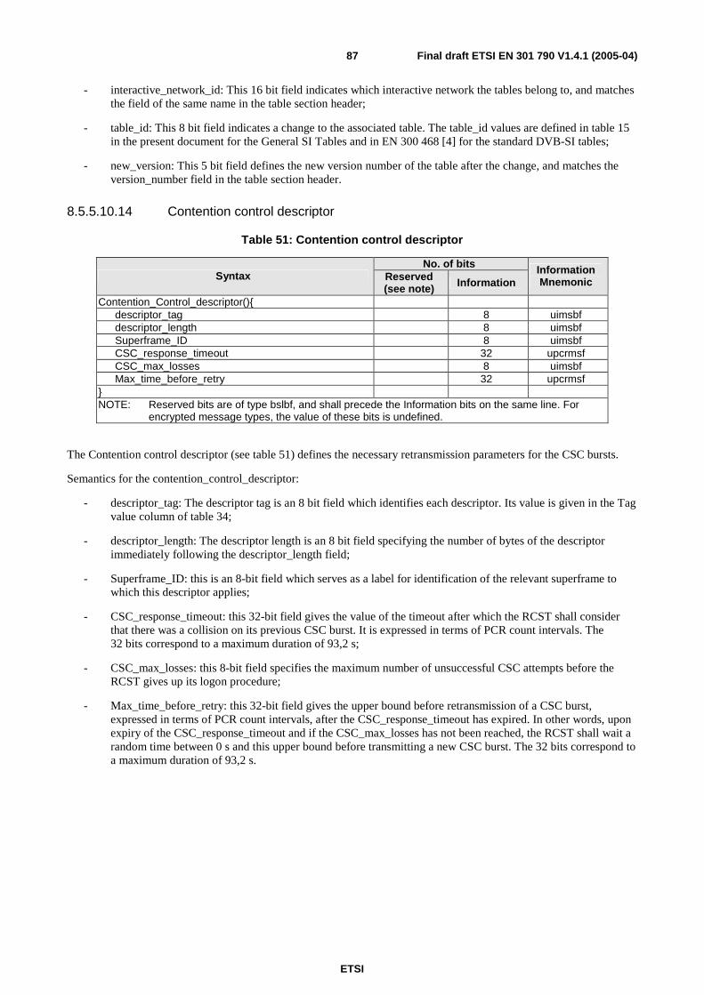
ETSI
Final draft ETSI EN 301 790 V1.4.1 (2005-04) 87
- interactive_network_id: This 16 bit field indicates which interactive network the tables belong to, and matches the field of the same name in the table section header;
- table_id: This 8 bit field indicates a change to the associated table. The table_id values are defined in table 15 in the present document for the General SI Tables and in EN 300 468 [4] for the standard DVB-SI tables;
- new_version: This 5 bit field defines the new version number of the table after the change, and matches the version_number field in the table section header.
8.5.5.10.14 Contention control descriptor
Table 51: Contention control descriptor
No. of bits Syntax Reserved
(see note) Information Information Mnemonic
Contention_Control_descriptor(){ descriptor_tag 8 uimsbf descriptor_length 8 uimsbf Superframe_ID 8 uimsbf CSC_response_timeout 32 upcrmsf CSC_max_losses 8 uimsbf Max_time_before_retry 32 upcrmsf } NOTE: Reserved bits are of type bslbf, and shall precede the Information bits on the same line. For
encrypted message types, the value of these bits is undefined.
The Contention control descriptor (see table 51) defines the necessary retransmission parameters for the CSC bursts.
Semantics for the contention_control_descriptor:
- descriptor_tag: The descriptor tag is an 8 bit field which identifies each descriptor. Its value is given in the Tag value column of table 34;
- descriptor_length: The descriptor length is an 8 bit field specifying the number of bytes of the descriptor immediately following the descriptor_length field;
- Superframe_ID: this is an 8-bit field which serves as a label for identification of the relevant superframe to which this descriptor applies;
- CSC_response_timeout: this 32-bit field gives the value of the timeout after which the RCST shall consider that there was a collision on its previous CSC burst. It is expressed in terms of PCR count intervals. The 32 bits correspond to a maximum duration of 93,2 s;
- CSC_max_losses: this 8-bit field specifies the maximum number of unsuccessful CSC attempts before the RCST gives up its logon procedure;
- Max_time_before_retry: this 32-bit field gives the upper bound before retransmission of a CSC burst, expressed in terms of PCR count intervals, after the CSC_response_timeout has expired. In other words, upon expiry of the CSC_response_timeout and if the CSC_max_losses has not been reached, the RCST shall wait a random time between 0 s and this upper bound before transmitting a new CSC burst. The 32 bits correspond to a maximum duration of 93,2 s.

ETSI
Final draft ETSI EN 301 790 V1.4.1 (2005-04) 88
8.5.5.10.15 Correction Control descriptor
The Correction control descriptor (see table 52) defines the necessary timeouts for the coarse synchronization, fine synchronization and synchronization maintenance procedures.
Table 52: Correction control descriptor
No. of bits Syntax Reserved
(see note) Information Information Mnemonic
Correction_Control_descriptor(){ descriptor_tag 8 uimsbf descriptor_length 8 uimsbf ACQ_response_timeout 32 upcrmsf SYNC_response_timeout 32 upcrmsf ACQ_max_losses 8 uimsbf SYNC_max_losses 8 uimsbf } NOTE: Reserved bits are of type bslbf, and shall precede the Information bits on the same line.
Semantics for the correction_control_descriptor:
- descriptor_tag: The descriptor tag is an 8 bit field which identifies each descriptor. Its value is given in the Tag value column of table 34;
- descriptor_length: The descriptor length is an 8 bit field specifying the number of bytes of the descriptor immediately following the descriptor_length field;
- ACQ_response_timeout: this 32-bit field gives the value of the timeout after which the RCST shall assume there was a problem on its previous ACQ burst. It corresponds to the "Correction received in time" test of the coarse sync procedure. It is expressed in terms of PCR count intervals. The 32 bits correspond to a maximum duration of 93,2 s;
- SYNC_response_timeout: this 32-bit field gives the value of the timeout after which the RCST shall assume there was a problem on its previous SYNC burst. It corresponds to the "Correction received in time" test of the fine sync and sync maintenance procedures. It is expressed in terms of PCR count intervals. The 32 bits correspond to a maximum duration of 93,2 s;
- ACQ_max_losses: this 8-bit field specifies the maximum number of consecutive ACQs with no correction received before expiry of ACQ_response_timeout. When this number is reached, the RCST shall return to the "Off/Stand-by" state. It corresponds to the "max losses exceeded" test of the coarse sync procedure (see clause 7.4);
- SYNC_max_losses: this 8-bit field specifies the maximum number of consecutive SYNCs with no correction received before expiry of SYNC_response_timeout. When this number is reached, the RCST shall return to the "Off/Stand-by" state. It corresponds to the "max losses exceeded" test of the fine sync procedure and of the sync maintenance procedure (see clauses 7.5 and 7.6).
8.5.5.10.16 Forward Interaction Path descriptor
The DVB standards for interactive services require a Forward Interaction Path and a Return Interaction. The Forward Interaction Path descriptor provides parameters that an RCST needs for finding on the forward link its traffic of the Forward Interaction Path. This descriptor is delivered to and utilized by an RCST when the RCST does not make use of the optional Connection Control descriptor.
The Forward Interaction Path descriptor is carried in a TIM. It is valid until it is overwritten by a new version. ("Wake-able" RCSTs in specific network architectures may continue to receive traffic on the assigned Forward Interaction Path after log off). Unicast TIMs allow distributing the RCSTs over the available forward link capacity. The NCC can assign one or more transport streams (i.e. transponders) to an RCST, depending on the number of receivers that the RCST contains. Therefore, the descriptor contains a loop over transport streams. On each transport stream the traffic can be carried in one or more PIDs, which are listed in a second loop.
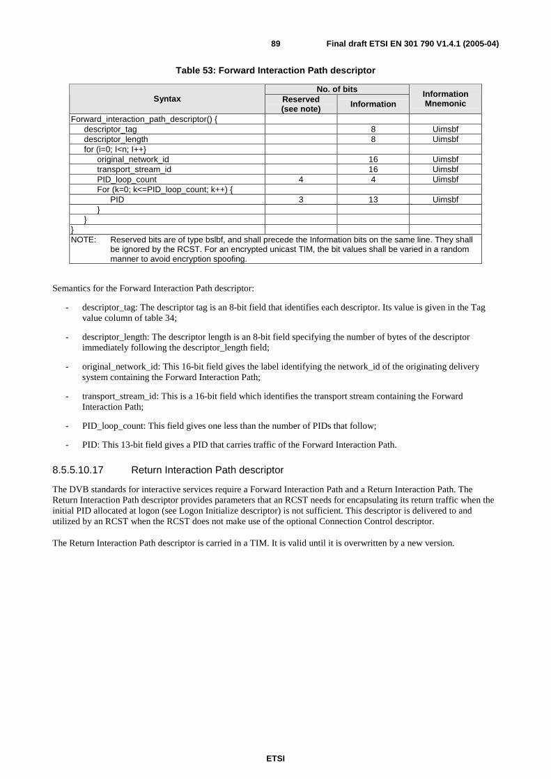
ETSI
Final draft ETSI EN 301 790 V1.4.1 (2005-04) 89
Table 53: Forward Interaction Path descriptor
No. of bits Syntax Reserved
(see note) Information Information Mnemonic
Forward_interaction_path_descriptor() { descriptor_tag 8 Uimsbf descriptor_length 8 Uimsbf for (i=0; I<n; I++} original_network_id 16 Uimsbf transport_stream_id 16 Uimsbf PID_loop_count 4 4 Uimsbf For (k=0; k<=PID_loop_count; k++) { PID 3 13 Uimsbf } } } NOTE: Reserved bits are of type bslbf, and shall precede the Information bits on the same line. They shall
be ignored by the RCST. For an encrypted unicast TIM, the bit values shall be varied in a random manner to avoid encryption spoofing.
Semantics for the Forward Interaction Path descriptor:
- descriptor_tag: The descriptor tag is an 8-bit field that identifies each descriptor. Its value is given in the Tag value column of table 34;
- descriptor_length: The descriptor length is an 8-bit field specifying the number of bytes of the descriptor immediately following the descriptor_length field;
- original_network_id: This 16-bit field gives the label identifying the network_id of the originating delivery system containing the Forward Interaction Path;
- transport_stream_id: This is a 16-bit field which identifies the transport stream containing the Forward Interaction Path;
- PID_loop_count: This field gives one less than the number of PIDs that follow;
- PID: This 13-bit field gives a PID that carries traffic of the Forward Interaction Path.
8.5.5.10.17 Return Interaction Path descriptor
The DVB standards for interactive services require a Forward Interaction Path and a Return Interaction Path. The Return Interaction Path descriptor provides parameters that an RCST needs for encapsulating its return traffic when the initial PID allocated at logon (see Logon Initialize descriptor) is not sufficient. This descriptor is delivered to and utilized by an RCST when the RCST does not make use of the optional Connection Control descriptor.
The Return Interaction Path descriptor is carried in a TIM. It is valid until it is overwritten by a new version.

ETSI
Final draft ETSI EN 301 790 V1.4.1 (2005-04) 90
Table 54: Return Interaction Path descriptor
No. of bits Syntax Reserved
(see note) Information Information Mnemonic
Return_interaction_path_descriptor() { descriptor_tag 8 uimsbf descriptor_length 8 uimsbf Network_Routing_Label_loop_Count 4 4 uimsbf For (i=0; i<= Network_routing_Label_loop_Count; i++) {
Allocation_Desallocation_flag 1 blsbf PID_flag 1 blsbf If (PID_flag == 1) { PID_loop_count 8 uimsbf For (j=0; j<= PID_loop_Count; j++) { blsbf PID 3 13 uimsbf } } VPI/VCI_flag 1 blsbf If (VPI/VCI_flag == 1) { VPI/VCI_loop_count 8 uimsbf For (k=0; k<= VPI/VCI_loop_Count; k++) { VPI 8 uimsbf VCI 16 uimsbf } } Route_ID_flag 1 blsbf If (Route_ID_flag == 1) { Route_ID_loop_count 8 uimsbf For (l=0; l<= Route_ID_loop_Count; l++) { Route_ID 16 uimsbf } } Channel_ID 4 uimsbf } } NOTE: Reserved bits are of type bslbf, and shall precede the Information bits on the same line. They shall
be ignored by the RCST. For an encrypted unicast TIM, the bit values shall be varied in a random manner to avoid encryption spoofing.
Semantics for the Return Interaction Path descriptor:
- descriptor_tag: The descriptor tag is an 8-bit field that identifies each descriptor. Its value is given in the Tag value column of table 34;
- descriptor_length: The descriptor length is an 8-bit field specifying the number of bytes of the descriptor immediately following the descriptor_length field;
- Network_Routing_Label_Loop_count: this field indicating one less than the number of iteration of the frame loop that follows. A zero count indicates one loop;
- Allocation_Desallocation_flag: This one-bit field indicates whether this is a Network_Routing_labels assignment to the RCST (the flag should then be set to 1) or a de-assignment (the flag should then be set to 0);
- PID_flag: The value "1" indicates that the descriptor contains PIDs. The value "0" indicates that the descriptor does not contains PIDs;
- PID_Loop_count: this field indicating one less than the number of PID that follows. A zero count indicates one PID;
- PID: This 13-bit field gives a PID that the RCST shall use in optional MPEG2 TS traffic packets on Return Interaction Path;

ETSI
Final draft ETSI EN 301 790 V1.4.1 (2005-04) 91
- VPI/VCI_flag: The value "1" indicates that the descriptor contains VPI/VCIs. The value "0" indicates that the descriptor does not contains VPI/VCIs;
- VPI/VCI_Loop_count: this field indicating one less than the number of VPI/VCI that follows. A zero count indicates one VPI/VCI pair;
- VPI: This 8-bit field gives a VPI that the RCST shall use in ATM traffic packets on Return Interaction Path;
- VCI: This 16-bit field gives a VCI that the RCST shall use in ATM traffic packets on Return Interaction Path;
- Route_ID_flag: The value "1" indicates that the descriptor contains route_IDs. The value "0" indicates that the descriptor does not contains route_IDs;
- Route_ID__Loop_count: this field indicating one less than the number of route_ID that follows. A zero count indicates one route_ID;
- Route_ID: This 16-bit field gives a route_ID that the RCST shall use in prefixed ATM traffic packets on Return Interaction Path;
- Channel_ID: This 4-bit field indicates the channel with which the Network_Routing_labels value shall be associated in the RCST. Values are managed by the NCC. This value is used to provide differentiated QoS and/or for connectivity purposes.
8.5.5.10.18 Connection Control descriptor (optional)
The Connection Control descriptor provides a mechanism by which signalling information are passed to the Control Plane of a RCST during connection control phases. As such, the message content is passed transparently through the lower layers covered by the present document and is not defined here. The descriptor is defined in table 55.
Table 55: Connection Control descriptor
Syntax No. of bits Mnemonic Connection_Control_descriptor(){ descriptor_tag 8 uimsbf descriptor_length 8 uimsbf Message_body see text }
Semantics for the Connection_Control_descriptor:
- descriptor_tag: The descriptor tag is an 8 bit field which identifies each descriptor. Its value is given in the Tag value column of table 34;
- descriptor_length: The descriptor length is an 8 bit field specifying the number of bytes of the descriptor immediately following the descriptor_length field;
- message_body: This variable length field shall contain a connection control signalling message for passing to the target connection control entity. The length of the message body shall not exceed 255 bytes and should preferably be limited such that the section containing this descriptor fits within a single TS packet.
8.5.5.11 Accessing of the forward link signalling
Service Information for Forward Link Signalling (FLS) shall be transmitted in one or more Forward Link Signalling services. Being a DVB data service, the FLS service shall be referenced like any other DVB service in the Program Association Table (PAT), Program Map Table (PMT) and optionally Service Description Table (SDT). If contained in the SDT, the service_type shall be set to 0x0F for "RCS FLS". The PMT of the FLS service shall contain the PIDs for the NCR, the General SI tables and RCST specific messages as defined in the present document.

ETSI
Final draft ETSI EN 301 790 V1.4.1 (2005-04) 92
Additional information about the Satellite Interactive Network shall be conveyed in a RCS Map Table (RMT). This table having the same syntax as the NIT - but being transmitted on a different PID - shall contain one or more linkage descriptors pointing to one or more FLS services. Each linkage descriptor shall contain a list of population_ids, which are being used by the RCST to select its appropriate FLS service. For this purpose the RCST has a default population_id for the installation process which may be changed at a later stage and be memorized for following network logons. The population_id values are unique on the satellite network.
An interactive network is defined by a group of terminals serviced by a single NCC. In the simplest case, each NCC handles a single interactive network, however a large NCC logically splits its capacity into several interactive_networks. A population is a subset of a particular interactive network.
For the purposes of the present document, the forward link acquisition procedure is concerned with acquiring the forward link that carries the Forward Link Signalling service. This forward link acquisition procedure comprises the following steps:
- physical link synchronization;
- forward link location;
- NCR synchronization;
- DVB-RCS specific table loading.
Physical link synchronization is the process of tuning to the required transponder, recovering the transmitted signal and synchronizing to the DVB transport stream formatting on that signal. This shall be done each time an RCST is required to move to a different transponder.
Forward link location is the procedure for identifying which transponder carries the Forward Link Signalling service, and for identifying the PIDs. This procedure uses three standard DVB table types as follows:
- Network Information Table (NIT);
- Program Allocation Table (PAT);
- Program Map Table (PMT).
The detailed procedure for forward link location shall be as defined below in this section. It should be noted that this procedure may involve tuning to a maximum of three transponders in sequence, requiring a physical link synchronization for each transponder.
An outline of the forward link location procedure flow is shown in figure 35. This procedure requires that the following parameters be stored at the RCST as power-up configuration data:
- location details for forward link start-up Transport Stream (TS). This can be any Transport Stream in the network. The parameters correspond to those defined in the satellite_delivery_system_descriptor of EN 300 468 [4];
- population_ID value.
The RCST shall tune to the start-up Transport Stream and scan the copy of the NIT to locate the Transport Stream carrying the RMT. This shall be identified by locating the linkage descriptor containing the linkage_type code (0x07) for the RCS Map service. It shall use the TS_id parameter from that linkage descriptor to locate the satellite_delivery_system_descriptor for that Transport Stream (in the second loop of the NIT), and hence the tuning details for the Transport Stream, which carries the RMT.
The RCST shall then re-tune (if necessary) to the Transport Stream carrier that carries the RMT and shall load the RMT using the assigned PID. It shall scan the RCS Map Table for all linkage_descriptors containing the RCS FLS service linkage_type code 0x81, to find the descriptor containing its population_id (in the private data extension to that descriptor type). This descriptor will also contain the Interactive_network_id to be used by that RCST, together with the TS_id for the Transport Stream to be used by the RCST for logon and the service_id to be used by the PAT later.

ETSI
Final draft ETSI EN 301 790 V1.4.1 (2005-04) 93
The RCST shall then locate the entry for that TS_id in the second loop of the RCS Map Table and extract the satellite forward link and satellite return link descriptors. Where there are multiple instances of these, then it shall extract the signalling satellite forward link and the primary satellite return link as a minimum, and use these for the balance of the procedure. These descriptors contain initial parameters required by the subsequent Return Link Acquisition process, namely the satellite_id for both forward and return links, the gateway_id for the return link, the NCC_id for forward link, plus the superframe_id and transmit centre frequency offset for the return link. The RCST shall then re-tune (if necessary) to the Transport Stream carrier carrying its forward link signalling, using the parameters defined in the signalling satellite forward link descriptor, and locate the PAT entry with prg_nbr parameter equal to the service_id. This defines the PID for the associated PMT.
From the PMT, it shall extract the PID for the PCR Insertion packet (PCR_PID), and the PIDs for the RCS specific signalling tables. These PIDs are identified by locating those stream definitions containing the RCST content descriptor (defined in clause 8.5.5.10.10), and associating the table_id's for RCS tables with the elementary_PID value defined for that stream.
The result of this forward link location procedure shall be the following:
- identification of the NCC and satellite for the Forward Link Signalling service;
- identification of the Gateway and satellite for the return link;
- definition of the PIDs for the DVB-RCS forward signalling messages;
- definition of the superframe to be used for the return link logon procedure.
NCR synchronization is the procedure for locking the RCST timing to the NCR count at the NCC. This shall be done by receiving the PCR Insertion Transport Stream Packet (see clause 8.5.5.6) at the transmitted interval and deriving a synchronous PCR count and PCR clock locally in the RCST that are locked to the PCR count in that packet. Upon successful acquisition of the receive NCR, the RCST shall continue to monitor it. As a matter of safety if the reception of the forward link is interrupted, the RCST shall cease transmission if conditions defined in clause 7.7.3 are fulfilled.
DVB-RCS specific table loading. The RCST shall load the following tables, using the PIDs identified in the forward link location procedure:
- SCT, FCT, and TCT to identify the available superframe and frame structures;
- SPT to obtain the satellite ephemeris data for the forward link signalling satellite and return link satellite;
- TIM (broadcast version) to identify possible link anomalies.
In addition, the RCST shall monitor for unicast TIM messages addressed to the RCST MAC address for possible wake-up messages.
An RCST is capable of receiving DVB-S only, DVB-S2 only, or both. In a network that shall support the first two kinds, the RCS Map Table must be transmitted simultaneously on a transponder with DVB-S and a transponder with DVB-S2. Different Population IDs for the three kinds link each RCST to an FLS and forward link traffic that it can receive.

ETSI
Final draft ETSI EN 301 790 V1.4.1 (2005-04) 94
TIM PID=830table_id=0xB0 MAC address message_type { message content }
linkage_descr [RCS Map 1] (optional)TS_id(=1088)orig_network_id (=0x01)service_id(=811)linkage_type=0x07 private data [spare]
linkage_descr [RCS Map 1]TS_id(=1071)orig_network_id(=X)service_id(=810)linkage_type=0x07 [RCS Map service] private data [spare]
stream_type=0x05 [private section]elementary_PID(=831)RCS content desscriptor table_id=0xA5 [TBTP] table_id=0xA4 [CMT]
CMT PID=831table_id=0xA4{table content}
SPT PID=820table_id=0xA3{table content}
TCT PID=820table_id=0xA2{table content}
RCS Map Table PID(=Y) [assigned through PAT,PMT]table_id=0x41network_idnetwork_name_descr
linkage_descr [information service]TS_id(=2088)orig_network_id (=0x02)service_id(=11)linkage_type(=0x01) [info service]
NIT PID=0x0010table_id=0x40network_idnetwork_name_descr
linkage_descr [CA repl. service]TS_id(=2071)orig_network_id (=0x02)service_id(=10)linkage_type=(0x03) [CA repl. serv]
linkage_descr [EPG]TS_id(=1088)orig_network_id (=0x01)service_id(=11)linkage_type(=0x02) [EPG service]
linkage_descr [information service]TS_id(=1071)orig_network_id(=X)service_id(=10)linkage_type(=0x01) [info service]
TS_id(=2089)orig_network_id (=0x02)
service_list_descr (optional)srvc_id(=?) srvc_type=(?)srvc_id(=?) srvc_type=(?)srvc_id(=?) srvc_type=(?)srvc_id(=?) srvc_type=(?)
satellite_delivery_descrfrequency(=12,18750)orbital_position=0,282west_east_flag; polarization;modulation; symbol_rate; FEC_inner
TS_id(=1089)orig_network_id (=0x01)
service_list_descr (optional)srvc_id(=?) srvc_type=(?)srvc_id(=?) srvc_type=(?)srvc_id(=?) srvc_type=(?)srvc_id(=?) srvc_type=(?)
satellite_delivery_descrfrequency(=12,18750)orbital_position=0,192west_east_flag; polarization;modulation; symbol_rate; FEC_inner
TS_id(=1071)orig_network_id (=X)
service_list_descr (optional)srvc_id(=28000) srvc_type=(dig TV)srvc_id(=28001) srvc_type=(dig TV)srvc_id(=11) srvc_type=(0x80 u.d.)srvc_id(=810) srvc_type=(0x0E )
satellite_delivery_descrfrequency(=011,80000)orbital_positionwest_east_flag; polarization;modulation; symbol_rate; FEC_inner
PMT PID(=802)table_id=0x02prg_nbr(=802)PCR_PID(=0x1600) [PCR Insertion TS Packet]CA_descr [if required]PDSD [private_data_specifier_descr] (optional)private_descr [spare] (optional)
1
linkage_descr [Forward signalling 1]TS_id(=1071)orig_network_id (=X)service_id(=801)linkage_type=0x81 private data
[interactive_network_idlist of population_ids]
3
linkage_descr [Forward signalling 2]TS_id(=1088)orig_network_id (=X)service_id(=802)linkage_type=0x81 [RCS FLS service] private data
{ interactive_network_id list of population_ids }
PAT PID=0x0000table_id=0x00TS_id (=1088) prg_nbr=0 network_PID=0x0010 [NIT] prg_nbr(=27050) PMT_PID(=512) [TV channel 1] prg_nbr(=27051) PMT_PID=(513) [TV channel 2] prg_nbr(=28153) PMT_PID(=514) [Data Carrousel] prg_nbr(=1303) PMT_PID(=524) [IP DATA in MPE 7] prg_nbr(=1304) PMT_PID(=525) [IP DATA in MPE 8] prg_nbr(=1304) PMT_PID(=525) [DATA in ATM 4] prg_nbr(=802) PMT_PID(=802) [Forward signalling 2] prg_nbr(=803) PMT_PID(=803) [Forward signalling 3]
5
6
FCT PID=820table_id=0xA1{table content}
SCT PID=820table_id=0xA0{table content}
transponder 71any transponder on satellite network
transponder 88
1 = seek tuning parameters for RCS Map Table2 = access RCS Map Table3 = seek tuning parameters for Forward Signaling Service ("Forward signalling 2") with matching interactive_network_id and population_id4 = do tuning (if necessary) and look for PAT5 = access PMT of selected Forward Signaling Service6 = get PIDs for SCT, FCT, TCT, TIM, TBTP, CMT, SPT,etc.
2
stream_type=0x0D [DSM-CC section]elementary_PID(=830)RCS content descriptor table_id=0xB0 [TIM]
TBTP PID=831table_id=0xA5{table content}
4
stream_type=0x05 [private section]elementary_PID(=820)RCS content descriptor table_id=0xA0 [SCT] table_id=0xA1 [FCT] table_id=0xA2 [TCT] table_id=0xA3 [SPT]
TS_id(=1071)orig_network_id (=0x01)
service_list_descr (optional)srvc_id(=?) srvc_type=(?)srvc_id(=?) srvc_type=(?)srvc_id(=?) srvc_type=(?)srvc_id(=802) srvc_type=(0x0F)
satellite_delivery_descrfrequency(=011,83650)orbital_position=019,2west_east_flag; polarization;modulation; symbol_rate; FEC_inner
TS_id(=1088)orig_network_id (=X)
satellite_return_link_descrsatellite_id(=0x06)gateway_idorbital_positionwest_east_flagSuperframe_ID(=0x42)Tx_frequency_offset(=0)
satellite_forward_link_descrsatellite_id(=0x23)NCC_idfrequency(=12,10000)orbital_positionwest_east_flag; polarization;modulation; symbol_rate; FEC_inner
service_list_descr (optional)srvc_id(=27050) srvc_type(=0x01)srvc_id(=27051) srvc_type(=0x01)srvc_id(=28153) srvc_type(=0x0C)srvc_id(=802) srvc_type=0x0F [RCS FLS]
Figure 35: Example of forward link location

ETSI
Final draft ETSI EN 301 790 V1.4.1 (2005-04) 95
8.5.5.12 RCS Map Table
The RCS Map Table enables to link different populations of RCSTs to specific FLS. The syntax is based on the syntax of the DVB Network Information Table that is defined in EN 300 468 [4].
The RCS Map Table shall contain one or multiple linkage descriptors each pointing to one FLS service. Each FLS service shall carry a set of signalling tables (SCT, TCT, FCT, SPT, TBTP, CMT) and TIMs for a defined RCST population. The linkage descriptor is defined in clause 8.5.5.10.9. An RCST selects its FLS service by comparing its own Population ID with the Population IDs listed in each of the linkage descriptors.
The RCS Map Table shall contain a loop over MPEG Transport Streams that carry FLS. For each of these MPEG Transport Streams it shall contain a Satellite Forward Link descriptors, which is defined in clause 8.5.5.10.11, and a Satellite Return Link descriptor, which is defined in clause 8.5.5.10.12.
The RCS Map Table shall be segmented into sections using the syntax of table 56.
Table 56: RCS Map Table
No. of bits Syntax Reserved Information
Information Mnemonic
RCS_map_section(){ table_id 8 uimsbf section_syntax_indicator 1 bslbf reserved_future_use 1 bslbf Reserved 2 bslbf section_length 12 uimsbf network_id 16 uimsbf Reserved 2 bslbf version_number 5 uimsbf current_next_indicator 1 bslbf section_number 8 uimsbf last_section_number 8 uimsbf reserved_future_use 4 bslbf network_descriptors_length 12 uimsbf for(i=0;i<N;i++){
descriptor() } reserved_future_use 4 bslbf transport_stream_loop_length 12 uimsbf for(i=0;i<N;i++){
transport_stream_id 16 uimsbf original_network_id 16 uimsbf reserved_future_use 4 bslbf transport_descriptors_length 12 uimsbf for(j=0;j<N;j++){ descriptor()
} }
CRC_32 32 rpchof }
Semantics for the RCS Map Table:
- table_id: This 8 bit field identifies the table. The value is 0x41;
- section_syntax_indicator: The section_syntax_indicator is a 1-bit field which shall be set to "1";
- section_length: This is a 12-bit field, the first two bits of which shall be "00". It specifies the number of bytes of the section, starting immediately following the section_length field and including the CRC. The section_length shall not exceed 1 021 so that the entire section has a maximum length of 1 024 bytes;
- network_id: This is a 16-bit field which serves as a label to identify the delivery system, to which the table shall apply;

ETSI
Final draft ETSI EN 301 790 V1.4.1 (2005-04) 96
- version_number: This 5-bit field is the version number of the sub_table. The version_number shall be incremented by 1 when a change in the information carried within the sub_table occurs. When it reaches value 31, it wraps around to 0. When the current_next_indicator is set to "1", then the version_number shall be that of the currently applicable sub_table defined by the table_id and _network_id_mask. When the current_next_indicator is set to "0", then the version_number shall be that of the next applicable sub_table defined by the table_id and _network_id;
- current_next_indicator: This 1-bit indicator, when set to "1" indicates that the sub_table is the currently applicable sub_table. When the bit is set to "0", it indicates that the sub_table sent is not yet applicable and shall be the next sub_table to be valid;
- section_number: This 8-bit field gives the number of the section. The section_number of the first section in the sub_table shall be "0x00". The section_number shall be incremented by 1 with each additional section with the same table_id and network_id;
- last_section_number: This 8-bit field specifies the number of the last section (that is, the section with the highest section_number) of the sub_table of which this section is part;
- network_descriptors_length: This 12-bit field gives the total length in bytes of the following network descriptors. Network descriptors shall contain the Network Name descriptor from EN 300 468 [4] and one or more linkage descriptors containing private data bytes as defined in clause 8.5.5.10.9. Additional descriptors from the NIT definition in EN 300 468 [4] are optional and the RCST does not need to use them;
- transport_stream_loop_length: This is a 12-bit field specifying the total length in bytes of the Transport Stream loops that follow, ending immediately before the first CRC-32 byte;
- transport_stream_id: This is a 16-bit field which serves as a label for identification of this Transport Stream from any other multiplex within the delivery system;
- original_network_id: This 16-bit field gives the label identifying the network_id of the originating delivery system;
- transport_descriptors_length: This is a 12-bit field specifying the total length in bytes of Transport Stream descriptors that follow. Transport Stream descriptors shall contain the Satellite Forward Path descriptor, which is defined in clause 8.5.5.10.11, and the Satellite Return Path descriptor, which is defined in clause 8.5.5.10.12. Additional descriptors from the NIT definition in EN 300 468 [4] are optional and the RCST does not need to use them;
- CRC_32: This is a 32 bit field that contains the CRC value that gives a zero output of the registers in the decoder defined in annex B of EN 300 468 [4] after processing the entire section.
8.5.5.13 Transmission Mode Support Table
The Transmission Mode Support Table defines the DVB-S2 transmission modes supported by the network for forward link transmission. If the forward link is transmitted using DVB-S2, then this table must be transmitted as part of the forward link signalling.
The table contains a loop over transmission mode definitions. MODCOD, pilot symbols and FECFRAME are defined in [19]. Use of this table is defined in clause 5.
The Transmission Support Mode Table shall be segmented into sections using the syntax defined in table 57.
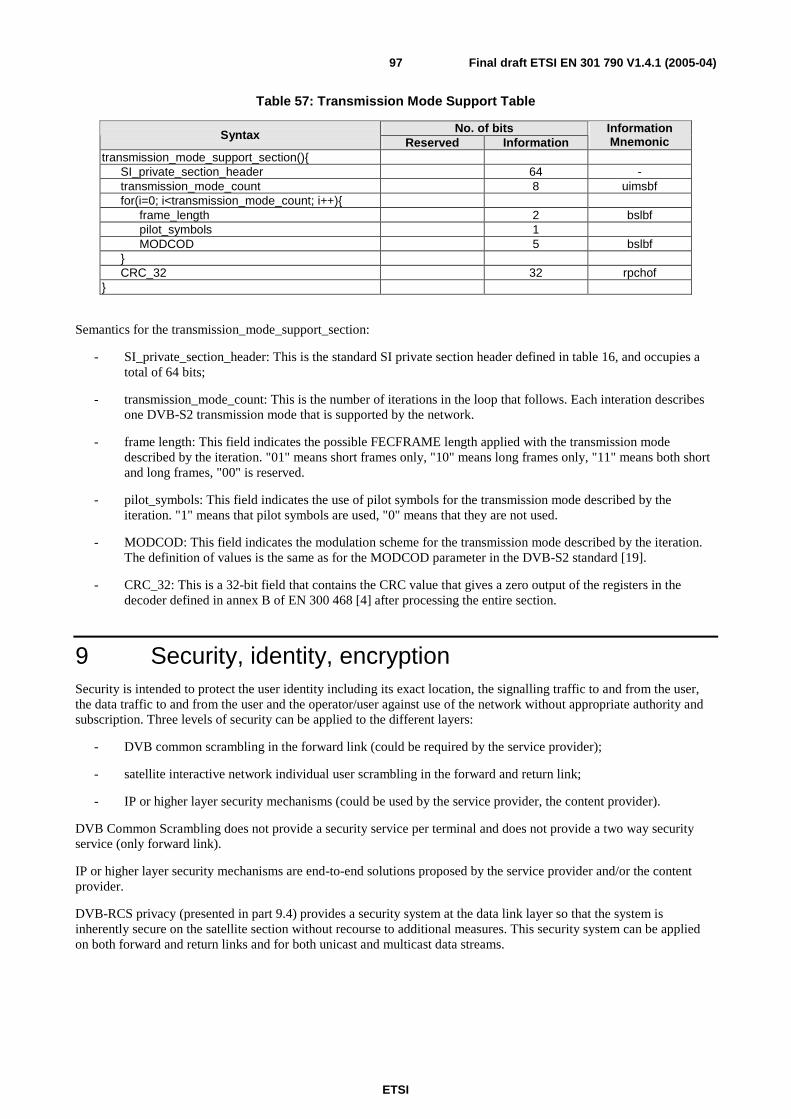
ETSI
Final draft ETSI EN 301 790 V1.4.1 (2005-04) 97
Table 57: Transmission Mode Support Table
No. of bits Syntax Reserved Information
Information Mnemonic
transmission_mode_support_section(){ SI_private_section_header 64 - transmission_mode_count 8 uimsbf for(i=0; i<transmission_mode_count; i++){ frame_length 2 bslbf pilot_symbols 1 MODCOD 5 bslbf } CRC_32 32 rpchof }
Semantics for the transmission_mode_support_section:
- SI_private_section_header: This is the standard SI private section header defined in table 16, and occupies a total of 64 bits;
- transmission_mode_count: This is the number of iterations in the loop that follows. Each interation describes one DVB-S2 transmission mode that is supported by the network.
- frame length: This field indicates the possible FECFRAME length applied with the transmission mode described by the iteration. "01" means short frames only, "10" means long frames only, "11" means both short and long frames, "00" is reserved.
- pilot_symbols: This field indicates the use of pilot symbols for the transmission mode described by the iteration. "1" means that pilot symbols are used, "0" means that they are not used.
- MODCOD: This field indicates the modulation scheme for the transmission mode described by the iteration. The definition of values is the same as for the MODCOD parameter in the DVB-S2 standard [19].
- CRC_32: This is a 32-bit field that contains the CRC value that gives a zero output of the registers in the decoder defined in annex B of EN 300 468 [4] after processing the entire section.
9 Security, identity, encryption Security is intended to protect the user identity including its exact location, the signalling traffic to and from the user, the data traffic to and from the user and the operator/user against use of the network without appropriate authority and subscription. Three levels of security can be applied to the different layers:
- DVB common scrambling in the forward link (could be required by the service provider);
- satellite interactive network individual user scrambling in the forward and return link;
- IP or higher layer security mechanisms (could be used by the service provider, the content provider).
DVB Common Scrambling does not provide a security service per terminal and does not provide a two way security service (only forward link).
IP or higher layer security mechanisms are end-to-end solutions proposed by the service provider and/or the content provider.
DVB-RCS privacy (presented in part 9.4) provides a security system at the data link layer so that the system is inherently secure on the satellite section without recourse to additional measures. This security system can be applied on both forward and return links and for both unicast and multicast data streams.
ETSI
Final draft ETSI EN 301 790 V1.4.1 (2005-04) 98
9.1 Authentication Authentication may be implemented by request for a user name or password on the client device. In the case of a PC used as the client device, the RCST does not need to carry any special implementation. However, if the RCST contains a proxy client, then the proxy may be able to authenticate itself to the NCC. This means that an authentication server may be implemented at the NCC, which manages the authentication of each user.
Authentication could also be replaced by a Smart Card on the RCST, also used for the link layer individual control word encryption.
9.2 Forward link DVB Common Scrambling could be required in the forward link.
Individual scrambling may be implemented at the section level, but the MAC address of the user may remain in the clear, since the RCST uses the MAC address to filter messages.
9.3 Return link The client device may handle IPsec, so the router at the Gateway may be able to handle IPsec.
Individual layer 2 scrambling may also be implemented.
9.4 Security (optional) The optional security mechanism described here is derived from the one used in [14].
The RCSTs indicates in the CSC bursts if it implements this option. The NCC indicates in the logon initialize descriptor if this mechanism is to be used. This security mechanism consists of two separate sub-systems:
- a set of MAC messages used for authentication and key-agreement between NCC and RCST. These messages are used for key negotiation during a session setup as well as for on-the-fly update of keys (see clause 9.4.7);
- on-the-fly encryption and decryption of payload data streams.
When a session is being setup, one of three request/response MAC message-pairs is used to generate session keys specific to the payload streams associated with the session.
A session key is a shared secret between the NCC and the RCST: even if every MAC message is intercepted, the cryptographic properties of the protocol ensure that an eavesdropper cannot determine the session key value.
This is achieved by using a public-key protocol, which requires an up-front shared secret, or a simpler protocol based on a long-term shared secret between NCC and RCST called a cookie. The cookie is 160 bits long. It can be used by the NCC to authenticate the RCST logon.
Each RCST will store its own cookie in non-volatile storage, whereas the NCC will maintain a data-base of the cookie values of the RCSTs on its network. Cookie values will be updated occasionally as de-stated by security policy, but they are less vulnerable than session keys: a successful brute-force attack on a session key reveals nothing about the cookie value, nor any other session key.
The MAC messages also implement a defence against clones: an RCST that is a physical copy of an existing RCST and attempts to operate on the network under the cloned identity (when the cloned RCST itself is not registered on the network). The anti-cloning measure is a simple non-volatile 8-bit counter that is incremented synchronously at the NCC and RCST over time: if a clone RCST engages in traffic with the NCC, this will be detected the next time the cloned RCST connects because the counter value will be out of synchronization.
If the clone attempts to operate concurrently with the cloned unit, there will be an immediate break-down of functionality for both units, due to confusion within the MAC protocol. This amounts to a denial-of-service attack, and the NCC should be prepared for this kind of protocol failure.

ETSI
Final draft ETSI EN 301 790 V1.4.1 (2005-04) 99
9.4.1 Cryptographic primitives
The key exchange protocols and data stream encryption is based on a set of well-established primitive cryptographic functions. The functions and their associated key sizes can be changed in the future, in case crypt-analytic or brute-force attacks become a realistic threat.
The specific set of functions and key sizes are negotiated between NCC and RCST at sign-on time. The functions supported at the present time are Diffie-Hellman, HMAC-SHA1, DES and AES. Check current cryptographic literature for any updates regarding their security and use.
The following sections give a brief overview of the cryptographic primitives, and details on how they are used in the protocol. Later sections describe the exact field layout of the MAC messages.
The protocol parameters are described in terms of byte strings. Integer quantities are represented as base-256 byte strings.
Big-endian byte-ordering is used, that is, the most significant byte comes first. If necessary to reach a fixed length, the string is padded with zeros at the most significant end.
9.4.1.1 Public key exchange
A public key exchange primitive is used to allow the NCC and RCST to agree on a secret, although communicating in public. The Diffie-Hellman scheme is based on unsigned integer arithmetic and works as follows.
The NCC chooses two public values, a large prime number m, and a (small) number g which is a generator modulo m
(that is, g^a mod m will generate all number from 0 to m-1 for varying a). The NCC also chooses a
secret number x < m, and sends the following three values to the RCST: m, g, X = g^x mod m.
The RCST chooses a secret value y < m, and responds to the NCC with the value Y = g^y mod m.
The RCST now calculates s = X^y mod m = (g^x)^y mod m = g^(x*y) mod m, whereas the NCC calculates
Y^x mod m = (g^y)^x mod m = g^(y*x) = s, so the NCC and RCST now agree on the value s.
The value of s is a secret shared between NCC and RCST. To determine its value from the publicly communicated
values m, g, X, and Y, an eavesdropper shall determine x or y by solving an equation of the form Z = g^z mod m
for unknown z. This is known as the discreet logarithm problem and is computationally infeasible with current
algorithms for sufficiently large values of m.
The parameter size supported are 512 bits for the prime number m, and hence also for the remaining values since all
arithmetic is modulo m.
In the applicable MAC messages, the unsigned integer quantities m, g, X, and Y are encoded into fixed-size fields (64 bytes, 96 bytes or 128 bytes) using big-endian byte-ordering.
9.4.1.2 Hashing
The protocol makes use of a keyed hash function that computes secure checksums which can only be verified with the possession of a secret key. The function has the one-way property, meaning that it is computationally infeasible to find an input value that maps to a given output value.
The hash function is also used to generate derived secret material based on a master secret. Because of the one-way property, the master secret is protected even if the derived secret is discovered.
In generic terms, the keyed hash function takes two byte strings as input, the key and a data string, and produces
another string of bytes, the digest:
- digest = H (key, data).

ETSI
Final draft ETSI EN 301 790 V1.4.1 (2005-04) 100
The H function shall accept key and data parameters of any size, whereas the protocol is designed to accept digests of any size.
The specification currently supports the HMAC-SHA1 function defined in RFC 2104 [15]. It produces a 20-byte digest.
9.4.1.3 Encryption
Payload data is encrypted and decrypted using symmetric-key block ciphers.
The specification currently supports two particular modes of operation to be associated to those symmetric-key block ciphers:
- Cipher Block Chaining (CBC) mode;
- Counter (CTR) mode.
Cipher Block Chaining Mode
In generic terms, the encryption and decryption functions take three byte strings as input, the key, an Initialization Vector (IV) and a data block, and produce as output another data block of the same length. The Cipher Block Chaining mode requires input plaintext blocks to be an exact multiple of the cipher block size. Padding operations are then necessary:
- ciphertext = E (key, IV, plaintext);
- D (key, IV, ciphertext) = plaintext.
The key length, IV length and block length is given by the chosen cipher, and the payload stream processing logic will apply it as appropriate to data units of various sizes.
The IV is an explicit non secret random binary value used as the initializing input algorithm for the encryption of the plaintext. A new IV value is calculated for every plaintext block to cipher. The IV must be unpredictable.
The IV value is conveyed in its clear form with the ciphertext. It precedes the protected (encrypted) payload.
The specification currently recommends AES algorithm in CBC mode implying a 16 bytes random value (IV) to be generated for every plaintext block and transmitted with the resulting ciphertext.
The specification also supports DES algorithm in CBC mode with an initialization vector set to zero.
Counter Mode
Inputs of the encryption and decryption functions for a counter mode approach are identical to the CBC mode except the Initialization vector to be replaced by a counter parameter:
- ciphertext = E (key,counter, plaintext);
- D (key,counter, ciphertext) = plaintext.
The key length and block length are given by the chosen cipher, and the payload stream processing logic will apply it as appropriate to data units of various sizes.
Counter characteristics (length, generation and manipulation) are also context specific. General requirement is that a counter value must not be used more than once associated to a given session key.
The specification currently support AES algorithm in CTR mode with the following counter usage:
- Counter length is 16 Bytes;
Counter is made of three parts noted as nonce (4 bytes) , counter (8 bytes), and block counter (4 bytes). Sub counter part values are big-endian integer values.

ETSI
Final draft ETSI EN 301 790 V1.4.1 (2005-04) 101
Nonce
The nonce value is a random value to be associated to a given session key. The value is transmitted with each session key during EKE exchanges (see 9.4.4). The same nonce value is then used for a given exchanged key.
Master counter
The master counter is a dynamic counter value to be associated to a session key.
It is managed by the senders this way:
- The master counter is set to 0 whenever beginning ciphering with a new session key.
- The master counter is then incremented by one for each plaintext to encrypt.
The master counter value is conveyed in its clear form with the ciphertext. It precedes the protected (encrypted) payload.
Block Counter
The block counter field is the least significant 4 bytes of the counter block. The bloc counter is set up to the value one for each plaintext to cipher (It will be incremented internally to generate subsequent portions of the key stream).
Two remarks are to be associated to such a management and format of the counter parameter:
- Re-keying operations must be conducted taking into account that the counter value has to be unique for a given session key. Situation authorizes no more than 2^64 plaintext blocks to be ciphered with the same key.
- Due to the size of the block counter part of the counter, the maximum length of a plaintext block to be ciphered is 68 719 476 720 octets
9.4.1.4 Pseudo-random numbers
The protocols used for generating secret values depend on the availability of a pseudo-random, that is, practically unpredictable, endless string of bytes. This will typically be produced with a Pseudo-Random Number Generator, PRNG, algorithm.
The random bytes are used to generate the secret Diffie-Hellman values, x and y, and for nonce values used during key exchange. The unpredictable nature of the random input ensures that different secret values are produced each time, that a necessary randomness is associated to plaintext in order to limit cryptanalysis tasks and also prevents replay of old intercepted messages.
The present document does not require any particular algorithm, only that the NCC and RCST each choose one that is well-established and cryptographically analysed.
The hardest aspect of using a PRNG is to initialize it with an unpredictable seed value. The seed should contain multiple high-granularity device-dependent time-samples, as well as any other available pseudo-random material, like file allocation tables, etc. These random source values are then hashed together to squeeze out the entropy for the seed value.
9.4.1.5 Padding
Modes of operation related to cipher algorithms may require input plaintext blocks to be an exact multiple of the cipher block size. Padding operations are then necessary.
Corresponding padding scheme to use is:
- The padding bytes are initialized with a series of (unsigned, 1-byte) integer values. The first padding byte appended to the plaintext is numbered 1, with subsequent padding bytes making up a monotonically increasing sequence: 1, 2, 3, etc.
- Whenever the plaintext block size is a multiple of the cipher block size, a complete block of padding equal to the size of the cipher block size and following the previous scheme is to be added.
Previous rules allow the receiving part to unambiguously remove padding data after the deciphering operation.

ETSI
Final draft ETSI EN 301 790 V1.4.1 (2005-04) 102
The specification currently supports:
- AES algorithm in CBC which uses a block size of 16 octets. Padding operations are then required to maintain a 16-octet block size.
- DES algorithm in CBC which uses a block size of 8 octets. Padding operations are then required to maintain a 8-octet block size.
It is to note that AES in CTR does not require padding data.
9.4.2 Main Key Exchange (MKE)
Main Key Exchange (MKE) uses Diffie-Hellman to develop a shared secret between the NCC and RCST, which is independent of the cookie value. Furthermore, it uses the cookie value to authenticate the RCST to the NCC. It optionally uses the newly developed shared secret to update the cookie value. Finally, it derives a shared secret key used for the security context that is used to process payload stream data.
The exchange is initiated by the NCC sending a message containing the Diffie-Hellman values, m, g, X, and a random
nonce string, nonce1. The RCST responds with a message containing its Diffie-Hellman value, Y, a random nonce
string, nonce2, and an authentication string, auth.
The NCC and RCST each use the same formula to calculate the authentication string:
- auth = H (cookie, nonce1 ~ nonce2);
which is communicated by the RCST and checked by the NCC. This proves the identity of the RCST, since it requires
knowledge of the cookie to calculate the correct value of auth.
The RCST and NCC each use the Diffie-Hellman values (see clause 9.4.1.1) to arrive at the same secret value, s:
- s = g^(x*y) mod m.
This unsigned integer value is encoded as a byte string, of length specified by the Diffie-Hellman parameter size, using
big-endian byte ordering. It is then used to calculate a temporary shared secret string, temp:
- temp = H (encode (s), nonce2 ~ nonce1).
If the cookie is to be updated, the new value is computed in sections for n = 1, 2, …:
- newcookie(n) = H (temp ~ (unsigned char)1 ~ (unsigned char)n, "").
These string values are computed and concatenated until the total length matches or exceeds the length of the cookie. The cookie is then obtained by taking the first 20 bytes out of the concatenated sections, starting from the beginning.
The session key used for payload stream encryption is likewise computed in sections:
- key(n) = H (temp ~ (unsigned char) 2 ~ (unsigned char) n, "").
Where, again, a sufficient number of sections are calculated to produce enough bytes to cover the length of the key. The session key is obtained "in the same manner as the cookie" by taking the required number of bytes out of the concatenated sections, starting from the beginning.

ETSI
Final draft ETSI EN 301 790 V1.4.1 (2005-04) 103
9.4.3 Quick Key Exchange (QKE)
Quick Key Exchange (QKE) uses the existing cookie value to authenticate the RCST to the NCC, and then derive a shared secret key used for the security context that is used to process payload stream data.
The exchange is initiated by the NCC sending a message containing a random nonce string, nonce1. The RCST
responds with a message containing a random nonce string, nonce2, and an authentication value, auth.
The value of auth is calculated in the same way as for Main Key Exchange, and can be used to verify the identity of the RCST (see clause 9.4.2).
The RCST and NCC then each calculate a temporary shared secret string, temp:
- temp = H (cookie ~ (unsigned char)3 , nonce2 ~ nonce1).
This value is used to produce the payload encryption key in the same way as for Main Key Exchange (see clause 9.4.2).
9.4.4 Explicit Key Exchange (EKE)
Explicit Key Exchange (EKE) is used by the NCC to deliver a pre-determined session key to the RCST. The session key is encrypted under a temporary key derived from the cookie value, and is used for the security context that is used to process payload stream data.
The delivery is performed by the NCC sending a message containing a random nonce string, nonce1, and a byte string
value, encryptedkey, which has the same length as a key used for payload encryption. The RCST responds with a
message containing a random nonce string, nonce2, and an authentication value, auth.
The value of auth is calculated in the same way as for Main Key Exchange, and can be used to verify the identity of the RCST (see clause 9.4.2).
Both the NCC and RCST calculate a temporary shared secret string, temp:
- temp = H (cookie ~ (unsigned char)4, nonce1).
which is used to produce sections of a temporary key, in the same way as for Main Key Exchange (see clause 9.4.2).
The NCC uses these temporary key string sections to XOR with the session key to obtain the encryptedkey value, and the RCST performs a second XOR operation to decrypt the session key value.
For normal DES, 8 bytes of raw key data are delivered, which are used to derive the actual key with the appropriate number of effective bits, as described below (see clause 9.4.2).
For AES, 16 bytes of raw key are delivered, which are used to derive the actual key with the appropriate number of effective bits, as described below (see clause 9.4.2).
9.4.5 Key derivation
The actual key value used for processing payload data is derived from the key sections developed during key exchange.
For DES, 8 bytes of raw key data is required, so a single 20-byte section, key(1), computed by HMAC-SHA1 is sufficient.
For AES, 16 bytes of raw key data is required, so a single 20-byte section, key(1), computed by HMAC-SHA1 is sufficient. In each byte, the least significant bit is not used (it can be used as an odd-parity bit of the remaining 7 bits), bringing the effective key size down to 56 bits. Furthermore, when DES is used in 40-bit mode, the two most significant bits of each byte in the key are zeroed.

ETSI
Final draft ETSI EN 301 790 V1.4.1 (2005-04) 104
9.4.6 Data stream processing
Security can be applied to various payload data streams selectively. The elementary unit is called a security context, which contains two session keys used for encrypting and decrypting a stream of payload data. Only one of the keys is used to process any particular payload unit. Each key can be used for processing both upstream and downstream payload data.
Having two keys allows negotiation of a new key to take place while payload data is processed using the old one, and then do an immediate switch-over once the new key is agreed upon, without interrupting payload traffic. The NCC initiates the key exchanges, and can start using a session key for downstream traffic encryption once the key exchange is complete. For upstream traffic encryption, the RCST should use whichever key was used by the NCC in the most recent encrypted payload unit.
9.4.6.1 Payload streams
A payload stream is identified by either of:
- a 24-bit (UNI) ATM virtual circuit VPI/VCI;
- a 48-bit MAC-address: this is used for DVB Multiprotocol Encapsulation downstream payload data.
When a payload stream is secured, the RCST and the NCC will have matching security contexts, which are used to encrypt/decrypt both upstream and downstream traffic. For unsecured payload streams there is no security context, and payload data is not encrypted.
To support encrypted multi-cast traffic, the same security context will be created for each member using EKE (see clause 9.4.4), so that each RCST can decrypt the common payload data stream.
9.4.6.2 Data encryption
Within a payload data stream, data is carried in individual units at the various protocol layers. Encryption is applied at the lowest layer possible, consistent with the payload stream:
- The unit of encryption is the payload field of an AAL5 CPCS-PDU. This payload is encrypted using the security context implied by the stream.
- DVB Multiprotocol Encapsulation payload streams: the unit of encryption is a single DVB Multiprotocol Encapsulation section. The datagram_data_bytes (between the MAC-address and the CRC/checksum) are encrypted using the security context implied by the stream. As defined in clause 9.4.1.5, the DVB Multiprotocol Encapsulation payload to be encrypted will be adjusted to have a length of n × 8 bytes (n is an integer) for the DES algorithm, n × 16 bytes for the AES algorithm by adding an appropriate amount of stuffing bytes before the CRC/checksum according to EN 300 468 [4], annex B after processing the entire section. The CRC/checksum is calculated on the encrypted datagram bytes, while higher-level protocol layers see only unencrypted datagrams.
9.4.6.3 Encryption flags
There are flags in the header of each encryption unit specifying which of the two sessions keys of the security context is used.
The receiver will use the security context of the payload stream to see if decryption shall be done.
AAL5 payload: Bit 0 and 1 of the CPCS-UU field contained within the CPCS-PDU Trailer of any AAL5 CPCS-PDU is used to convey security information as illustrated below.
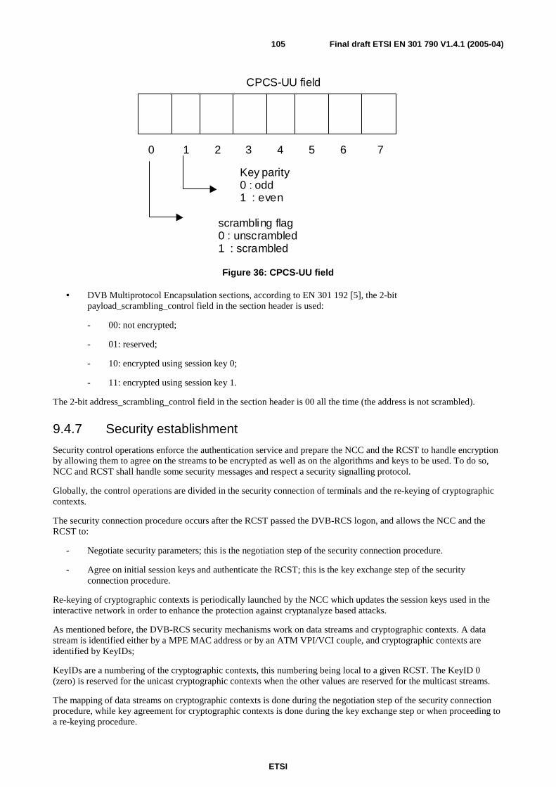
ETSI
Final draft ETSI EN 301 790 V1.4.1 (2005-04) 105
0 1 2 3 4 5 6 7
CPCS-UU field
scrambling flag 0 : unscrambled 1 : scrambled
Key parity 0 : odd 1 : even
Figure 36: CPCS-UU field
• DVB Multiprotocol Encapsulation sections, according to EN 301 192 [5], the 2-bit payload_scrambling_control field in the section header is used:
- 00: not encrypted;
- 01: reserved;
- 10: encrypted using session key 0;
- 11: encrypted using session key 1.
The 2-bit address_scrambling_control field in the section header is 00 all the time (the address is not scrambled).
9.4.7 Security establishment
Security control operations enforce the authentication service and prepare the NCC and the RCST to handle encryption by allowing them to agree on the streams to be encrypted as well as on the algorithms and keys to be used. To do so, NCC and RCST shall handle some security messages and respect a security signalling protocol.
Globally, the control operations are divided in the security connection of terminals and the re-keying of cryptographic contexts.
The security connection procedure occurs after the RCST passed the DVB-RCS logon, and allows the NCC and the RCST to:
- Negotiate security parameters; this is the negotiation step of the security connection procedure.
- Agree on initial session keys and authenticate the RCST; this is the key exchange step of the security connection procedure.
Re-keying of cryptographic contexts is periodically launched by the NCC which updates the session keys used in the interactive network in order to enhance the protection against cryptanalyze based attacks.
As mentioned before, the DVB-RCS security mechanisms work on data streams and cryptographic contexts. A data stream is identified either by a MPE MAC address or by an ATM VPI/VCI couple, and cryptographic contexts are identified by KeyIDs;
KeyIDs are a numbering of the cryptographic contexts, this numbering being local to a given RCST. The KeyID 0 (zero) is reserved for the unicast cryptographic contexts when the other values are reserved for the multicast streams.
The mapping of data streams on cryptographic contexts is done during the negotiation step of the security connection procedure, while key agreement for cryptographic contexts is done during the key exchange step or when proceeding to a re-keying procedure.
ETSI
Final draft ETSI EN 301 790 V1.4.1 (2005-04) 106
The authenticity of the RCST can be checked by the NCC during the key exchange step and during a re-keying procedure.
Security connection of a RCST
From the beginning here is how the security issues are handled at connection time:
• When an RCST registers on the network it will first go through the normal logon procedure as described in clause 7. It can then do negotiation handshakes with the NCC to defined the protected streams and to establish the level of security support, in particular the cryptographic algorithms and key sizes to be used subsequently. During logon, the RCST indicates its encryption/security capability to the NCC on the CSC burst (see clause 6.2.3) and the NCC communicates on the logon initialize descriptor (see clause 8.5.5.10.4) whether security shall be used.
• If security is used, the NCC then starts the security connection procedure with the negotiation step by sending as many Sign On request messages as the data streams required by the RCST. For Sign On request messages related to multicast forward MPE streams, the NCC selects only one encryption algorithm in its proposal, as the cryptographic context will be shared by all the RCSTs of the network. The RCST shall then reply to each message issuing a Sign On response message including its choices. A failure during the negotiation step causes the RCST to be logged off from the DVB-RCS network.
• Once the negotiation step is completed, the NCC shall proceed with the key exchange step by sending EKE request messages for each cryptographic context handled in the previous step. The NCC can request for the RCST to increment its clone counter. The RCST replies to each EKE request message with an EKE response message including its clone counter as well as an "authenticator" value. When receiving an EKE response message, the NCC can authenticate the terminal based on the clone counter and the "Authenticator" value. If the RCST has to increment its clone counter, it transmits the value of the clone counter before incrementation. A failure during the key exchange step of the connection causes the RCST to be logged off from the DVB-RCS network.
Re-keying
The NCC can start a re-keying procedure to update the session key of a cryptographic context. To transmit a new key, the NCC shall send EKE request messages, as for the key exchange step of the connection operation. For multicast cryptographic contexts, the NCC shall transmit an EKE request message to each concerned RCST.
The RCSTs shall extract session keys from incoming EKE request messages and reply with EKE response messages. Clone counter values cannot be updated during re-keying operations. While a cryptographic context is being updated, the old key shall still be used. For downlink streams, the gateway can start ciphering with the new key only upon reception of the EKE response message (or all the EKE response messages for a multicast cryptographic context). For an uplink stream, the ST can switch to the new key as soon as it receives the EKE request message.
A failure during this stage of the protocol causes the RCST to be logged off.
9.4.8 Persistent state variables
To facilitate authentication, key exchange, and clone detection, the RCST has a set of state variables whose values are retained across registrations and power cycles.
Table 58: Persistent RCST variables
Name Function Size Cookie authentication cookie 160 bits Cookie_SN cookie sequence number 1 bit Clone_Counter clone detection counter 8 bits Clone_Counter_SN clone counter sequence number 1 bit
The sequence numbers are used to ensure that the NCC and RCST can stay synchronized even in case the RCST drops off the net in the middle of a protocol exchange.

ETSI
Final draft ETSI EN 301 790 V1.4.1 (2005-04) 107
9.4.8.1 Guaranteed delivery
The NCC will ensure that a protocol exchange is complete before proceeding. If it does not receive a response MAC message within a given time-interval, it will re-transmit the original message unchanged. The RCST will do likewise in situations where it requires a response. If the number of re-transmissions exceeds three, the protocol fails.
Due to race conditions, superfluous re-transmissions may be generated by both NCC and RCST. They shall discard such messages after the first message has in fact been received.
If the RCST is not ready to respond within the specified time-out, it can send <MAC>Wait messages (see clause 9.4.9.9) to extend the time it has available to generate a proper response. Upon receiving the wait message, the NCC will restart its timer and reset the retry count.
The protocol time-out values can be set by the <MAC> Default Configuration Message as defined in clause 5.5.3.2 of [14], otherwise the following default values apply.
Table 59: Protocol time-out values
Code Protocol stage Default Value 0xD Security Sign-On 700 0xE Main Key Exchange 1 200 0xF Quick Key Exchange
Explicit Key Exchange 900
The Unit for the timeouts is ms.
9.4.9 Security MAC messages
The following presents the security messages defined in the DVB-RCS framework. Two pairs of request/response messages are defined, one aiming at negotiating security parameters, the other allowing to agree on session keys as well as to authenticate RCSTs.
The following table details the roles played by each pair of messages.
Table 60: Security MAC messages roles
Pair of messages Role Sign On request and Sign On response
At the negotiation step of the connection procedure: Allows to associate cryptographic contexts to data streams. Allows to negotiate algorithms and parameters.
EKE request and EKE response
At the key exchange step of the connection procedure and during re-keying procedures: Allows the NCC to provide the RCSTs with session keys. Allows the NCC to authenticate RCSTs.
Request messages are sent by the NCC to the RCSTs and response messages are sent by the RCSTs to the NCC.
9.4.9.1 <MAC>Security Sign-On
As part of the registration process when an RCST performs the logon, the NCC and RCST will negotiate the specific set of cryptographic algorithms and parameters used in the key exchange protocols and for payload encryption.
The selections are global, and apply to all subsequent security exchanges for as long as the RCST is registered on the network.
The selections affect the layout of the subsequent key exchange messages, since they have fields that vary in size according to the choice of algorithms and parameters.
The NCC indicates which algorithms and parameters it supports by setting the appropriate bits in the <MAC>Security Sign-On message. There are four classes of algorithms, and the NCC will set one or more bits in each of the four fields to indicate which specific choices it supports.

ETSI
Final draft ETSI EN 301 790 V1.4.1 (2005-04) 108
The Sign On request message is presented in table 61. One Sign On request message associates a cryptographic context, indicated by the Key_Id field, to a data stream indicated by the Flow_Id field.
Negotiation applies to the specified keyId and involves four classes: public key algorithm (used for the Main Key Exchange), hashing algorithms, encryption algorithms, and Nonce sizes. The Sign On message carries the propositions made by the NCC to the RCST in the fields Public_Key_Alg, Hash_Alg, Encryption_Alg and Nonce_Size as follow: for each class, the NCC proposes to the RCST a possible value by setting the corresponding bit to "1".
Table 61: Security Sign-On message structure
Security_Sign-On (){ Bits Bytes Bit Number/Description Parameter bytes
Public_Key_Alg 1 Public key algorithm choices: Ppka:
PKA_Reserved PKA_DH_512
7 1
7..1: Reserved, shall be 0 0:(yes/no) Diffie-Hellman, 512 bits
64
Hash_Alg 1 Hash algorithm choices: Pha:
HA_Reserved HA_HMACSHA1
7 1
7..1: Reserved, shall be 0 0:(yes/no) HMAC-SHA1
20
Encryption_Alg 1 Encryption algorithm choices: Pea:
EA_Reserved EA_AES_CTR_128 EA_AES_CBC_IV_128 EA_DES_56 EA_DES_40
4 1 1 1 1
7..4: Reserved, shall be 0 3: AES in counter mode, 128 bits key 2: AES in CBC mode, with a random IV, 128 bits key 1:(yes/no) DES, 56 bit key 0:(yes/no) DES, 40 bit key
24 16
8
Nonce_Size 1 Nonce size choices: Pns:
NS_Reserved NS_64 NS_64
7 1
7..1: Reserved, shall be 0 0: (yes/no) 8 random bytes
8
Security_Ctxt_Version_Flow Id_Type Flow_Id Key_Id
1 1 24 6
4 32: the version of the security protocol. Shall be set to zero. 31: The type of stream designated by the message. If "Id_Type" is 0, then the 23 lowest bits of Flow_Id are the 23 lowest bits of the stream's MAC address. Else Flow_Id is an ATM VPI/VCI couple. 7..30: identify the data stream 1..6: the keyID of the cryptographic context
}
If the security option is supported, the minimum subset to support is PKA_DH_512, HA_HMACSHA1, EA_DES_40, and NS_64. EA_DES_56 is optional.
The Sign On request message indicates the data stream with the Flow_Id field. The meanning of this field depends on the value of Id_Type:
If Id_Type is set to "0", the data stream is a MPE stream, and Flow_Id is set as follow:
• If the stream is a the unicast stream of the RCST, Flow_Id is set to zero, as well as Key_Id.
• If the stream is a multicast MPE stream, the 23 lowest bits of Flow_Id are the 23 lowest bits of the stream's MAC address, as specified in RFC 1112.

ETSI
Final draft ETSI EN 301 790 V1.4.1 (2005-04) 109
If Id_Type is set to "1", the data stream is an ATM PVC, and Flow_Id is the VPI/VCI of the PVC as follows:
VPI (8 bits) VCI (16 bits)
Figure 37: Flow_Id when Id_Type is set to "1"
9.4.9.2 <MAC>Security Sign-On Response
In its security sign-on response, the RCST indicates which specific algorithms and parameters to use. It does so by choosing one of the suggestions offered by the NCC within each of the four classes.
The fields of the response message have the same definition as the message from the NCC, except that exactly one bit will be set in each field.
If the RCST is unable to support any of the suggested algorithms for any class, it shall return an all-zero field value, and the NCC will revert to non-secure communication or re-issue the <MAC>Security Sign-On message with different choices. In this case, the NCC will logoff the RCST.
Table 62: Security Sign-On Response message structure
Security_Sign-On_Response() {
Bits Bytes Bit Number/Description Parameter bytes
Public_Key_Alg 1 Public key algorithm choices: Ppka:
PKA_Reserved PKA_DH_512
7 1
7..1: Reserved, shall be 0 0:(yes/no) Diffie-Hellman, 512 bits
64
Hash_Alg 1 Hash algorithm choices: Pha:
HA_Reserved HA_HMACSHA1
7 1
7..1: Reserved, shall be 0 0:(yes/no) HMAC-SHA1
20
Encryption_Alg 1 Encryption algorithm choices: Pea:
EA_Reserved EA_AES_CTR_128 EA_AES_CBC_IV_128 EA_DES_56 EA_DES_40
4 1 1 1 1
7..4: Reserved, shall be 0 3: AES in counter mode, 128 bits key 2: AES in CBC mode, with a random IV, 128 bits key 1:(yes/no) DES, 56 bit key 0:(yes/no) DES, 40 bit key
24 16
8
Nonce_Size 1 Nonce size choices: Pns:
NS_Reserved NS_64
7 1
7..1: Reserved, shall be 0 0: (yes/no) 8 random bytes
8
Security_Ctxt_Version_Flow Id_Type Flow_Id Key_Id
1 1 24 6
4 32: the version of the security protocol. Shall be set to zero. 31: The type of stream designated by the message. If "Id_Type" is 0, then the 23 lowest bits of Flow_Id are the 23 lowest bits of the stream's MAC address. Else Flow_Id is an ATM VPI/VCI couple. 7..30: identify the data stream 1..6: the keyID of the cryptographic context
}

ETSI
Final draft ETSI EN 301 790 V1.4.1 (2005-04) 110
9.4.9.3 <MAC>Main Key Exchange
The Main Key Exchange message is used to start a cookie-independent key exchange with the RCST, and also instructs the RCST whether to update its cookie value and clone counter value. The connection_id is not used and shall be set to all "0".
Table 63: Main Key Exchange message structure
Main_Key_Exchange () { Bits Bytes Bit Number/Description Connection_ID 32 4 MAC connection identifier Flags 1 Reserved FL_Initializing FL_Update_Cookie FL_Update_Counter FL_Session_Key
4 1 1 1 1
7..4: shall be 0 3:(yes/no) first ever key exchange 2:(yes/no) make new cookie value 1:(yes/no) increment clone counter 0: select session key 0 or 1
Reserved 8 1 Reserved for future use, shall be 0 Nonce Pns Random string nonce1 DH_Modulus Ppka Diffie-Hellman modulus m DH_Generator Ppka Diffie-Hellman generator g DH_Public_X Ppka Diffie-Hellman public value X }
The FL_Session_Key bit specifies which session key of the security context to update.
If the FL_Update_Counter bit is set, it instructs the RCST to increment its clone detection counter.
If the FL_Update_Cookie bit is set, it instructs the RCST to generate a new cookie value to be used for future authentications and key exchanges, and to reset the clone detection counter to zero.
If the FL_Initializing bit is set, it tells the RCST that the Authenticator field in the response will be ignored.
The sizes of the multi-byte fields are determined by the parameters of the algorithms selected during security sign-on (see clause 9.4.9.1).
The NCC will use its own private Diffie-Hellman value, x, together with the fields of the response message from the RCST to derive the new session key value, as well as any new value for the cookie (see clause 9.4.2).
9.4.9.4 <MAC>Main Key Exchange Response
The Main Key Exchange Response message authenticates the RCST and completes the cookie-independent key exchange with the NCC. It also contains the current value of the clone detection counter. The connection_id is not used and shall be set to all "0".
Table 64: Main Key Exchange Response message structure
Main_Key_Exchange_Response () { Bits Bytes Bit Number/Description Connection_ID 32 4 MAC connection identifier Flags 1 Reserved FL_Cookie_SN FL_cookie_SN FL_Counter_SN
6 1 1
7..2: shall be 0 1: cookie sequence number 0: clone counter sequence number
Clone_Counter 8 1 Current clone counter value Nonce Pns Random string nonce2 Authenticator Pha Authentication value auth DH_Public_Y Ppka Diffie-Hellman public value Y }

ETSI
Final draft ETSI EN 301 790 V1.4.1 (2005-04) 111
The FL_Counter_SN bit is the current sequence number of the clone detection counter. The Clone_Counter field is the current value of the counter. A clone collision has been detected if the NCC finds a mismatch from the expected value.
The FL_Cookie_SN bit is the sequence number of the cookie used for authentication.
If the FL_Update_Cookie bit was set by the NCC, the RCST will generate a new cookie value and complement the cookie sequence number bit. It will also reset the clone counter value to zero and clear the clone counter sequence number bit.
If the FL_Update_Counter bit was set by the NCC, the RCST will increment the value of the clone counter (modulo 256) and complement the clone counter sequence number bit.
Any updates to the cookie, clone counter, or their associated sequence number bits do not take effect, and shall not be committed to non-volatile storage, until the following <MAC>Connect Confirm message is received by the RCST.
The RCST uses its private Diffie-Hellman value, y, together with the message fields to derive the new session key value, as well as any new value for the cookie (see clause 9.4.2).
9.4.9.5 <MAC>Quick Key Exchange
The Quick Key Exchange message is used to start a cookie-dependent key exchange with the RCST, and also instructs the RCST whether to update its clone counter value. The connection_id is not used and shall be set to all "0".
Table 65: Quick Key Exchange message structure
Quick_Key_Exchange () { Bits Bytes Bit Number/Description Connection_ID 32 4 MAC connection identifier Flags 8 1 Reserved FL_Update_Counter FL_Session_Key
6 1 1
7..2: shall be 0 1:(yes/no) increment clone counter 0: select session key 0 or 1
Reserved 8 1 Reserved for future use, shall be 0 Nonce Pns Random string nonce1 }
The FL_Session_Key bit specifies which session key of the security context to update.
If the FL_Update_Counter bit is set, it instructs the RCST to increment its clone detection counter.
The NCC will use its knowledge of the cookie value together with the fields of the response message from the RCST to derive the session key value (see clause 9.4.3).
9.4.9.6 <MAC>Quick Key Exchange Response
The Quick Key Exchange Response message authenticates the RCST and completes the cookie-dependent key exchange with the NCC. It also contains the current value of the clone detection counter. The connection_id is not used and shall be set to all "0".
Table 66: Quick Key Exchange Response message structure
Quick_Key_Exchange_Response () { Bits Bytes Bit Number/Description Connection_ID 32 4 MAC connection identifier Flags 1 Reserved FL_Cookie_SN FL_Counter_SN
6 1 1
7..2: shall be 0 1: cookie sequence number 0: clone counter sequence number
Clone_Counter 8 1 Current clone counter value Nonce Pns Random string nonce2 Authenticator Pha Authentication value auth }

ETSI
Final draft ETSI EN 301 790 V1.4.1 (2005-04) 112
The FL_Cookie_SN bit is the sequence number of the cookie used for authentication.
The FL_Counter_SN bit is the current sequence number of the clone detection counter. The Clone_Counter field is the current value of the counter. A clone collision has been detected if the NCC finds a mismatch from the expected value.
If the FL_Update_Counter bit was set by the NCC, the RCST will increment the value of the clone counter (modulo 256) and complement the clone counter sequence number bit.
The RCST uses the cookie value together with the message fields to derive the session key value (see clause 9.4.3).
9.4.9.7 <MAC>Explicit Key Exchange
The Explicit Key Exchange message is used to securely deliver an existing session key value to the RCST, and also instructs the RCST whether to update its clone counter value.
Its layout, presented in the following table, is determined by the results of the negotiation step. This is indicated by parameters Pns and Pea.
The delivered session key applies to the cryptographic context specified by the Key_Id field.
The connection_id is not used and shall be set to all "0".
Table 67: Explicit Key Exchange message structure
Explicit_Key_Exchange (){ Bits Bytes Bit Number/Description Connection_ID 32 4 MAC connection identifier Key_Id 6 1 2..7: The KeyID to which the message
refers to Flags 1 FL_Update_Counter FL_Session_Key
6 1 1
7..2: shall be 0 1:(yes/no) increment clone counter 0: select session key 0 or 1
Nonce Pns Random string nonce1 Encryptedkey Pea Encrypted session key
}
The FL_Session_Key bit specifies which session key of the security context to update.
If the FL_Update_Counter bit is set, it instructs the RCST to increment its clone detection counter.
The NCC has used its knowledge of the cookie value to encrypt the session key value (see clause 9.4.4).
According to the cipher algorithm and usage, additional information may also be part of the transmission of the Encryptedkey. This is the case when using an AES CTR scheme. Nonce part of the counter must precede the protected (encrypted) session key. As the same session key may be used when bi-directional ciphering is used, two nonces are conveyed with the session key; one to be used by the NCC when ciphering (and the RCST when deciphering), the other to be used by the RCST when ciphering (and the NCC when deciphering).
When key material is only used for uni-directional ciphering, the useless nonce information is set to 0.
Payload
nonce part of
counter return link
4 Bytes
ciphered session key
nonce part of
counter forward link
16Bytes 4 Bytes
Figure 38: "Encrypted key" field format when using AES-CTR

ETSI
Final draft ETSI EN 301 790 V1.4.1 (2005-04) 113
9.4.9.8 <MAC>Explicit Key Exchange Response
The Explicit Key Exchange Response message authenticates the RCST and acknowledges receipt of the delivered key. It also contains the current value of the clone detection counter. The connection_id is not used and shall be set to all "0".
Table 68: Explicit Key Exchange Response message structure
Explicit_Key_Exchange_Response () { Bits Bytes Bit Number/Description Connection_ID 32 4 MAC connection identifier Key_Id 6 1 2..7: The KeyID of the association to
which the message refers to Flags FL_Cookie_SN FL_Counter_SN
1 1
1: cookie sequence number 0: clone counter sequence number
Clone_Counter 8 1 Current clone counter value Nonce Pns Random string nonce2 Authenticator Pha Authentication value auth }
The FL_Cookie_SN bit is the sequence number of the cookie used for authentication and session key decryption. If the NCC determines that it has used the wrong cookie for session key encryption it will re-issue the <MAC>Explicit Key Exchange using the old cookie value.
The FL_Counter_SN bit is the current sequence number of the clone detection counter. The Clone_Counter field is the current value of the counter. A clone collision has been detected if the NCC finds a mismatch from the expected value.
If the FL_Update_Counter bit was set by the NCC, the RCST will increment the value of the clone counter (modulo 256) and complement the clone counter sequence number bit.
The RCST uses the cookie value together with the message fields to decrypt the session key value (see clause 9.4.4).
9.4.9.9 <MAC>Wait
The Wait message is used by the RCST to extend the time the NCC waits for a reply to a given message. Upon receiving it, the NCC will reset its time-out value and retry count (see clause 9.4.8.1).
Table 69: Wait message structure
Wait () { Bits Bytes Bit Number/Description Connection_ID 32 4 MAC connection identifier Message_Type 8 1 Type of message from NCC Reserved 8 1 Reserved for future use, shall be 0 }
The Message_Type field is the message type value of the message received from the NCC being processed. The connection_id is not used and shall be set to all "0". The RCST indicates that it is currently unable to send a reply to the message.
9.5 Transport of security messages (optional) The MAC security messages transmitted over the air interface can be transported:
- Either using DULM (see clause 6.6.2) over the return path and using a dedicated and well-known PID over the forward path. "Security enhanced" RCSTs will thus have to MAC-filter this PID.
- Or using the same IP communication stack carrying the user and management traffic in the DVB-RCS network as shown below.

ETSI
Final draft ETSI EN 301 790 V1.4.1 (2005-04) 114
MPE
UDP
IP
MPEG2
DVB-S
ATM
AAL5
UDP
IP
ATM
MPE
MPEG2
AAL5
Forward link Return link
DVB-RCS
Figure 39: IP protocol stack for transporting security messages
Security messages are inserted in UDP datagrams with TLV descriptors, with the possibility to have several security messages per datagram as follows:
UDPheader
Typ
e
Leng
th
Typ
e
Leng
th
message messageTLV descriptor
MA
C @
Figure 40: Several security messages per datagram
For message transfers from a RCST to the NCC, the RCST's MAC address shall be inserted at the beginning of the UDP payload, as illustrated in the above figure. This MAC address allows the NCC to know from which RCST the messages are coming.
TLV descriptors allow to identify the type of the security messages with the following syntax:
Table 70: TLV descriptor structure
Security_TLV_descriptor { Bytes Parameter Type 1 Length 1 Mlen If (Type == 0x0d) { EKE message } if (Type == 0x35) { Sign On message }
Mlen Mlen
In the table above, the EKE message field can be either an EKE request message or an EKE response message, depending which entity sends it (NCC or RCST). The same remark applies to the Sign On message field.
The Length field is the length in bytes of the EKE message or Sign On message field.

ETSI
Final draft ETSI EN 301 790 V1.4.1 (2005-04) 115
Annex A (informative): Compliance table
Table A.1: RCST compliance table
PROFILE NAME Baseline ATM (option)
MPEG2 (option)
Baseline DVB-S2
ATM DVB-S2 MPEG2 DVB-S2
Access scheme Fixed MF-TDMA • • • • • •
Dynamic MF-TDMA ο ο ο ο ο ο Traffic Burst Format
ATM • • • • • • MPEG2 • •
Connectivity IP • • • • • •
Native ATM • ο • ο Channel Coding
RS • • • • • • Convolutional • • • • • •
Turbo • • • • • • CRC • • • • • •
Capacity Requests and management information
Prefix • • • • • • Data Unit Labelling • • • • • •
Mini-Slots • • • • • • Contention Mini-Slot • • • • • •
Security mechanism ο ο ο ο ο ο RCST forward link receivers
Single DVB-S • • • Multiple DVB-S ο ο ο Single DVB-S2 • • •
Multiple DVB-S2 ο ο ο • : Minimum Compliance Requirement for RCST. ο: Optional Compliance Point (statement by manufacturer).

ETSI
Final draft ETSI EN 301 790 V1.4.1 (2005-04) 116
Annex B (informative): Bibliography
• ITU-T Recommendation I.363-3: "B-ISDN ATM Adaptation Layer specification; Part 3: Type 3/4 AAL".
• ITU Radio Regulations.
• IETF RFC 1112: "Host extensions for IP multicasting".

ETSI
Final draft ETSI EN 301 790 V1.4.1 (2005-04) 117
History
Document history
V1.1.1 September 2001 Publication as TR 101 790
V1.2.1 January 2003 Publication as TR 101 790
V1.2.2 December 2000 Publication
V1.3.1 March 2003 Publication
V1.4.1 April 2005 One-step Approval Procedure OAP 20050826: 2005-04-27 to 2005-08-26
Related Documents