ETSI TR 101 790 V1.4.1 (2009-07) Technical Report Digital Video Broadcasting (DVB); Interaction channel for Satellite Distribution Systems; Guidelines for the use of EN 301 790 European Broadcasting Union Union Européenne de Radio-Télévision EBU·UER

Welcome message from author
This document is posted to help you gain knowledge. Please leave a comment to let me know what you think about it! Share it to your friends and learn new things together.
Transcript

ETSI TR 101 790 V1.4.1 (2009-07)
Technical Report
Digital Video Broadcasting (DVB);Interaction channel for Satellite Distribution Systems;
Guidelines for the use of EN 301 790
European Broadcasting Union Union Européenne de Radio-Télévision
EBU·UER
ETSI
ETSI TR 101 790 V1.4.1 (2009-07) 2
Reference RTR/JTC-DVB-239
Keywords broadcast, digital, DVB, satellite, TV
ETSI
650 Route des Lucioles F-06921 Sophia Antipolis Cedex - FRANCE
Tel.: +33 4 92 94 42 00 Fax: +33 4 93 65 47 16
Siret N° 348 623 562 00017 - NAF 742 C
Association à but non lucratif enregistrée à la Sous-Préfecture de Grasse (06) N° 7803/88
Important notice
Individual copies of the present document can be downloaded from: http://www.etsi.org
The present document may be made available in more than one electronic version or in print. In any case of existing or perceived difference in contents between such versions, the reference version is the Portable Document Format (PDF).
In case of dispute, the reference shall be the printing on ETSI printers of the PDF version kept on a specific network drive within ETSI Secretariat.
Users of the present document should be aware that the document may be subject to revision or change of status. Information on the current status of this and other ETSI documents is available at
http://portal.etsi.org/tb/status/status.asp
If you find errors in the present document, please send your comment to one of the following services: http://portal.etsi.org/chaircor/ETSI_support.asp
Copyright Notification
No part may be reproduced except as authorized by written permission. The copyright and the foregoing restriction extend to reproduction in all media.
© European Telecommunications Standards Institute 2009.
© European Broadcasting Union 2009. All rights reserved.
DECTTM, PLUGTESTSTM, UMTSTM, TIPHONTM, the TIPHON logo and the ETSI logo are Trade Marks of ETSI registered
for the benefit of its Members. 3GPPTM is a Trade Mark of ETSI registered for the benefit of its Members and of the 3GPP Organizational Partners.
LTE™ is a Trade Mark of ETSI currently being registered for the benefit of its Members and of the 3GPP Organizational Partners.
GSM® and the GSM logo are Trade Marks registered and owned by the GSM Association.
ETSI
ETSI TR 101 790 V1.4.1 (2009-07) 3
Contents
Intellectual Property Rights ................................................................................................................................9
Foreword...........................................................................................................................................................10
Introduction ......................................................................................................................................................10
1 Scope ......................................................................................................................................................12
2 References ..............................................................................................................................................12 2.1 Normative references .......................................................................................................................................13 2.2 Informative references......................................................................................................................................13
3 Definitions, symbols and abbreviations .................................................................................................16 3.1 Definitions........................................................................................................................................................16 3.2 Symbols............................................................................................................................................................17 3.3 Abbreviations ...................................................................................................................................................17
4 Reference models ...................................................................................................................................20 4.1 Architecture with co-located NCC, Gateway and Feeder.................................................................................20 4.2 Architecture with multiple feeders ...................................................................................................................21 4.3 Architecture with transparent mesh connectivity .............................................................................................21 4.4 Architecture with regenerative satellites ..........................................................................................................22 4.4.1 On board switching requirements ...............................................................................................................25 4.4.2 RSMS Network Architecture......................................................................................................................25
5 Forward link ...........................................................................................................................................26 5.1 Assignment and selection of FL elementary streams .......................................................................................27 5.2 Specific use of FL tables and formats ..............................................................................................................28 5.2.1 FL service specification in PMT.................................................................................................................28 5.2.1 Optional use of SDT ...................................................................................................................................28 5.2.2 Assumptions concerning IP encapsulation .................................................................................................28 5.3 Applicability of SI Tables in RSMS systems ...................................................................................................29
6 Return link..............................................................................................................................................29 6.1 RCST synchronization .....................................................................................................................................29 6.1.1 RCST internal delay compensation ............................................................................................................30 6.1.2 NCR interpretation for DVB-S2 .................................................................................................................30 6.1.3 DVB-S2 TX implementation aspects..........................................................................................................31 6.1.4 DVB-S2 RX implementation aspects .........................................................................................................32 6.1.5 VCM/ACM aspects and Multiple TS aspects .............................................................................................32 6.1.6 Combining TS and GS................................................................................................................................32 6.2 Burst format......................................................................................................................................................33 6.2.1 Contention access .......................................................................................................................................33 6.2.2 Acquisition Bursts ......................................................................................................................................33 6.2.3 Determination of the implicit number of MPEG2 packets in a burst..........................................................33 6.2.4 Application of MPE in the return link ........................................................................................................34 6.3 Randomization for energy dispersal .................................................................................................................34 6.4 Coding ..............................................................................................................................................................34 6.4.1 CRC error detection code ...........................................................................................................................34 6.4.1.1 CRC coding example ............................................................................................................................34 6.4.2 Reed Solomon outer coding........................................................................................................................35 6.4.3 Convolutional inner coding ........................................................................................................................35 6.4.4 Turbo code..................................................................................................................................................35 6.4.4.1 General principles of coding and decoding...........................................................................................35 6.4.4.2 Puncturing examples for DVB-RCS Turbo Code .................................................................................37 6.4.4.3 Implementation trade-offs .....................................................................................................................40 6.4.4.4 Implementation feasibility ....................................................................................................................41 6.4.5 Preferred coding combinations ...................................................................................................................41 6.4.5.1 Concatenated coding scheme ................................................................................................................41 6.4.5.2 Turbo coded systems.............................................................................................................................42
ETSI
ETSI TR 101 790 V1.4.1 (2009-07) 4
6.5 Modulation .......................................................................................................................................................42 6.5.1 BURST-TO-BURST interference control ..................................................................................................43 6.5.2 Control of EIRP, OBO and interference to adjacent channels ....................................................................43 6.6 MAC messages.................................................................................................................................................44 6.6.1 Methods based on the Satellite Access Control (SAC) field ......................................................................44 6.6.1.1 SAC field composition..........................................................................................................................44 6.6.2 Data Unit Labelling Method (DULM)........................................................................................................45 6.7 Multiple access .................................................................................................................................................45 6.7.1 Example for segmentation of return link capacity ......................................................................................46 6.7.1.1 ATM traffic time slots...........................................................................................................................46 6.7.1.2 Optional MPEG traffic time slots..........................................................................................................47 6.8 Capacity categories...........................................................................................................................................49 6.8.1 Request Classes and DS Behaviour Aggregates .........................................................................................49 6.8.2 Request Classes and Capacity Categories...................................................................................................50 6.8.3 Request Classes and Admission Control ....................................................................................................51 6.8.4 Guidelines for the Capacity Categories ......................................................................................................51 6.8.4.1 Continuous Rate Assignment ................................................................................................................51 6.8.4.2 Rate-Based Dynamic Capacity..............................................................................................................51 6.8.4.3 Volume-Based Dynamic Capacity ........................................................................................................52 6.8.4.4 Absolute Volume Based Dynamic Capacity .........................................................................................52 6.9 Queuing and packet dispatching strategy .........................................................................................................53 6.9.1 Guidelines for DS-compliant queueing and dispatching.............................................................................53 6.9.2 A two-stage traffic queueing DS architecture.............................................................................................53 6.10 Guidelines for the requesting strategy ..............................................................................................................55 6.10.1 BoD queue synchronization method ...........................................................................................................55 6.11 Assignment/allocation ......................................................................................................................................56 6.12 Procedure for contention resolution .................................................................................................................56
7 Synchronization procedures ...................................................................................................................56 7.1 Overall events sequencing................................................................................................................................56 7.2 Initial synchronization procedure .....................................................................................................................56 7.3 Logon procedure ..............................................................................................................................................56 7.3.1 Multiple correction message descriptors in TIM ........................................................................................57 7.4 Coarse synchronization procedure (optional)...................................................................................................57 7.5 Fine synchronization procedure (optional).......................................................................................................58 7.6 Synchronization maintenance procedure..........................................................................................................58 7.7 Logoff procedure..............................................................................................................................................58
8 Control and management........................................................................................................................58 8.1 Protocol stack ...................................................................................................................................................58 8.1.1 Transparent system .....................................................................................................................................58 8.1.2 Regenerative system ...................................................................................................................................58 8.2 RCST addressing..............................................................................................................................................58 8.3 Forward link signalling ....................................................................................................................................59 8.3.1 Repetition rates ...........................................................................................................................................60 8.3.2 DVB RCS SI table updates .........................................................................................................................60 8.3.3 Logon response TIM...................................................................................................................................61 8.3.4 Multicast Mapping Table............................................................................................................................61 8.3.4.1 MMT for MPE ......................................................................................................................................61 8.3.4.2 MMT for VC-MUX ..............................................................................................................................62 8.3.5 Other FL messages for network management (optional) ............................................................................63 8.4 Return Link Signalling .....................................................................................................................................63 8.4.1 Typically use of Return Link Signalling.....................................................................................................63 8.4.2 On board processing of Return Link Signalling .........................................................................................63 8.4.3 Other RL messages for network management (optional)............................................................................63 8.5 Coding of SI for forward link signalling ..........................................................................................................64 8.5.1 Table definition...........................................................................................................................................64 8.5.1.1 Timeslot Composition Table (TCT)......................................................................................................64 8.5.1.2 Terminal Burst Time Plan (TBTP)........................................................................................................64 8.5.2 DSM-CC Private Section Header ...............................................................................................................64 8.6 SNMP (optional) ..............................................................................................................................................64
9 Security, identity and encryption............................................................................................................65
ETSI
ETSI TR 101 790 V1.4.1 (2009-07) 5
10 RCST implementation guidelines ..........................................................................................................65 10.1 Architecture......................................................................................................................................................65 10.2 System performance .........................................................................................................................................66 10.2.1 RF/IF performance......................................................................................................................................66 10.2.2 Code performance in an AWGN channel ...................................................................................................68 10.2.2.1 Concatenated coding performance ........................................................................................................68 10.2.2.2 Turbo code performance .......................................................................................................................68 10.3 Interfaces ..........................................................................................................................................................69 10.3.1 RX IFL........................................................................................................................................................69 10.3.2 TX IFL........................................................................................................................................................70 10.3.3 ODU control signal .....................................................................................................................................71 10.3.3.1 Concept of the 22 kHz Pulse Width Keying (PWK) Bus......................................................................72 10.3.4 Control functions from the IDU..................................................................................................................74 10.3.5 Monitoring functions (from ODU on request) ............................................................................................74 10.3.6 Control and Monitoring protocol description .............................................................................................75 10.4 ODU environmental conditions........................................................................................................................75 10.4.1 Operational environment ............................................................................................................................75 10.4.2 Survival conditions .....................................................................................................................................75
11 User network guidelines.........................................................................................................................76 11.1 RCST interaction with cable and non-transparent SMATV.............................................................................76 11.2 Transparent SMATV........................................................................................................................................76 11.2.1 Interactive "one cable" SMATV-IF installation..........................................................................................77 11.2.2 Interactive "multiswitches equipped" SMATV-IF installation ...................................................................78 11.3 RCST interaction with local area networks ......................................................................................................81 11.4 RCST interaction with In-Home Digital Network............................................................................................84
Annex A: Examples of incorporation of satellite based return channel into a digital television platform .................................................................................................................................85
Annex B: RCST IDU/ODU IFL protocol description.........................................................................87
B.1 Command and request processing..........................................................................................................87
B.2 Alarms ....................................................................................................................................................87
B.3 Dynamic behaviour ................................................................................................................................87
B.4 Error recovery mechanism .....................................................................................................................87
B.5 Message level description ......................................................................................................................88 B.5.1 Framing field description .................................................................................................................................89 B.5.2 Address field description..................................................................................................................................90 B.5.3 Command field description (IDU → ODU) .....................................................................................................90 B.5.4 Password (optional)..........................................................................................................................................91 B.5.5 Extended message format.................................................................................................................................92 B.5.5.1 Extended messages for commands (IDU → ODU) ....................................................................................92 B.5.5.2 Simplified structure for short fixed length extended messages (IDU → ODU) .........................................93 B.5.5.3 Extended messages for replies (ODU → IDU)...........................................................................................93 B.5.6 CRC definition .................................................................................................................................................93 B.5.7 General implementation of functions ...............................................................................................................93 B.5.7.1 Reset status and parameter request .............................................................................................................94 B.5.7.1.1 ODU reset (0x0A) (optional) ................................................................................................................94 B.5.7.1.2 ODU Status (0x12)................................................................................................................................94 B.5.7.1.2.1 aa byte status description: Alarms ...................................................................................................95 B.5.7.1.2.2 bb byte status description: ODU state .............................................................................................95 B.5.7.1.2.3 cc byte status description: Reserved for future use..........................................................................95 B.5.7.1.3 ODU Identification (0x54, 0x55, 0x56, 0xD5) .....................................................................................95 B.5.7.2 Operational commands ...............................................................................................................................97 B.5.7.2.1 SSPA ON (0xC6) ..................................................................................................................................97 B.5.7.2.2 SSPA OFF (0xC7) ................................................................................................................................97 B.5.7.2.3 Transmitter disable (0xCE) ...................................................................................................................98 B.5.7.2.4 Transmitter enable (0xCF) ....................................................................................................................98 B.5.7.2.5 Set Power level (0xC8) (optional).........................................................................................................98
ETSI
ETSI TR 101 790 V1.4.1 (2009-07) 6
B.5.7.2.6 Mod ON (0xC9) (optional) ...................................................................................................................99 B.5.7.2.7 Mod OFF (0xCA) (optional) .................................................................................................................99 B.5.7.2.8 Set Rx Freq(0xD7) (optional) ...............................................................................................................99 B.5.7.2.9 Set Beacon Freq(0xD8) (optional) ........................................................................................................99 B.5.7.2.10 Set Tx Freq(0xD9) (optional)..............................................................................................................100 B.5.7.2.11 Set Satellite_ID(0xDA) (optional) ......................................................................................................100 B.5.7.2.12 Track OFF(0xDB) (optional) ..............................................................................................................100 B.5.7.2.13 Track ON(0xDC) (optional)................................................................................................................101 B.5.7.3 Download commands ...............................................................................................................................101 B.5.7.3.1 Download start (0xC1) (optional) .......................................................................................................101 B.5.7.3.2 Download data (0xC2) (optional) .......................................................................................................101 B.5.7.3.3 Download abort (0xC3) (optional) ......................................................................................................102 B.5.7.3.4 Download validate (0xC4) (optional) .................................................................................................102 B.5.7.3.5 Download toggle (0xC5) (optional) ....................................................................................................103 B.5.7.4 Password commands (optional) ................................................................................................................104 B.5.7.4.1 Change password (0xCB) (optional)...................................................................................................104 B.5.7.4.2 Validate password (0xCC) (optional) .................................................................................................104 B.5.7.4.3 Reset ODU locked (0xCD) (optional).................................................................................................105 B.5.7.5 Other functions (optional).........................................................................................................................105 B.5.7.5.1 ODU calibration table (0xD0) (optional) ............................................................................................105 B.5.7.5.2 ODU measured temperature (0xD1) (optional)...................................................................................106 B.5.7.5.3 ODU output power level (0xD2) (optional) ........................................................................................106 B.5.7.5.4 ODU location (0xD3) (optional) .........................................................................................................106 B.5.7.5.5 Set ODU location (0xD4) (optional) ...................................................................................................107 B.5.8 Command compatibility when SSPA ON ......................................................................................................107 B.5.9 Use of extended message structures ...............................................................................................................108
Annex C: Link budgets........................................................................................................................110
C.1 EIRP realization: implementation example..........................................................................................110
C.2 DVB-RCS return link-budget...............................................................................................................110
Annex D: Deriving Eb/N0 from ES/N0 - an example........................................................................113
D.1 Reed-Solomon/Convolutional Codes ...................................................................................................113
D.2 Turbo Codes .........................................................................................................................................113
Annex E: Example of used frequency bands .....................................................................................114
Annex F: MIB definition .....................................................................................................................115
Annex G: Example for a security and authentication concept.........................................................116
G.1 User authentication using RADIUS .....................................................................................................116 G.1.1 User authentication process............................................................................................................................116 G.1.2 User authentication message flow and steps ..................................................................................................117 G.1.2.1 User authentication accept message flow and steps..................................................................................117 G.1.2.2 User authentication reject message flow and steps ...................................................................................118 G.1.2.3 User authentication service provider challenge message flow and steps ..................................................119 G.1.3 User authentication message format...............................................................................................................120 G.1.3.1 Access_Request for user ...........................................................................................................................120 G.1.3.2 Access_ Reject..........................................................................................................................................120 G.1.3.3 Access_ Accept.........................................................................................................................................121 G.1.4 User Authentication Table..............................................................................................................................121 G.1.5 CHAP password crypto engine ......................................................................................................................124
G.2 IPSec solution and definition ...............................................................................................................124 G.2.1 SA negotiation and secure tunnel setup..........................................................................................................125 G.2.2 RCST SA re-negotiation ................................................................................................................................125 G.2.3 RCST Wake Up SA negotiation.....................................................................................................................126 G.2.3.1 RCST interfaces........................................................................................................................................126 G.2.4 Redundancy....................................................................................................................................................126
ETSI
ETSI TR 101 790 V1.4.1 (2009-07) 7
G.3 RCST security requirements ................................................................................................................126 G.3.1 Architecture overview ....................................................................................................................................126 G.3.2 Protection against violation ............................................................................................................................127 G.3.3 Containment of violation................................................................................................................................127 G.3.4 Recovery from violation.................................................................................................................................127
Annex H: Void ......................................................................................................................................128
Annex I: Example for procedures and operations providing additional functionality ................129
I.1 RCST software download ....................................................................................................................129
I.2 Installation and commissioning............................................................................................................129
I.3 RCST system processes........................................................................................................................129 I.3.1 RCST Power On.............................................................................................................................................130 I.3.2 RCST Reset ....................................................................................................................................................130 I.3.3 RCST Login ...................................................................................................................................................130 I.3.4 RCST Re-login...............................................................................................................................................130 I.3.5 RCST Logoff..................................................................................................................................................131 I.3.6 RCST Wake Up..............................................................................................................................................131 I.3.6.1 Traffic initiated RCST Wake Up ..............................................................................................................131 I.3.6.2 OAM RCST Wake Up..............................................................................................................................132 I.3.7 RCST Disable.................................................................................................................................................132 I.3.8 RCST Enable..................................................................................................................................................132 I.3.9 User Login......................................................................................................................................................132 I.3.10 User Logoff ....................................................................................................................................................132
I.4 State transition processes......................................................................................................................132 I.4.1 Name of transition in state machine ...............................................................................................................133 I.4.2 RCST operations state machine......................................................................................................................133 I.4.2.1 Forward Link Acquisition.........................................................................................................................133 I.4.2.2 OAM Acquisition .....................................................................................................................................134 I.4.2.3 Traffic Acquisition....................................................................................................................................135 I.4.2.4 Traffic Release..........................................................................................................................................136 I.4.2.5 OAM Release............................................................................................................................................137 I.4.2.6 Return Link Release..................................................................................................................................138 I.4.2.7 Return Link Disable..................................................................................................................................139 I.4.2.8 Return Link Enable...................................................................................................................................139 I.4.3 RCST configurations state machine ...............................................................................................................140 I.4.3.1 Encryption.................................................................................................................................................140 I.4.3.1.1 Phase 1 SA Acquisition.......................................................................................................................140 I.4.3.1.2 Phase 2 SA Acquisition.......................................................................................................................140 I.4.3.1.3 Phase 2 SA Release.............................................................................................................................141 I.4.3.1.4 Phase 1 SA Release.............................................................................................................................141 I.4.3.1.5 Full Encrypt Release ...........................................................................................................................141 I.4.3.1.6 Full Encrypt and Negotiate Release ....................................................................................................142 I.4.3.1.7 Phase 2 SA Re-negotiation..................................................................................................................142 I.4.3.1.8 Phase 2 SA Renewed ..........................................................................................................................143 I.4.3.2 RCST transmission ...................................................................................................................................143 I.4.3.2.1 Transmission Enable ...........................................................................................................................143 I.4.3.2.2 Transmission Disable ..........................................................................................................................143 I.4.3.3 User authentication state machine.............................................................................................................144 I.4.3.3.1 Normal user login to RCST.................................................................................................................144 I.4.3.3.2 Static user login to RCST....................................................................................................................144 I.4.3.3.3 RCST Re-login to NCC ......................................................................................................................145 I.4.3.3.4 Authentication successful....................................................................................................................145 I.4.3.3.5 Authentication failure - normal user ...................................................................................................145 I.4.3.3.6 Static user authentication failure .........................................................................................................146 I.4.3.3.7 Logoff from RCST - Not authenticated ..............................................................................................146 I.4.3.3.8 Logoff from RCST - authentication requested....................................................................................147 I.4.3.3.9 Logoff from RCST - authenticated .....................................................................................................148 I.4.3.3.10 RCST transition to INITIALIZED state..............................................................................................148
ETSI
ETSI TR 101 790 V1.4.1 (2009-07) 8
I.5 RCST Power Control............................................................................................................................148
I.6 Multicast Handling...............................................................................................................................149 I.6.1 Invoking a Multicast Session from RCST-side ..............................................................................................149 I.6.2 Revoking a Multicast Session from RCST-side .............................................................................................149 I.6.3 Multicast Source Transmission ......................................................................................................................150
Annex J: Example Connection Control Protocol .............................................................................151
Annex K: Example information exchange method between OBP and NCC for RSMS systems..152
Annex L: Applicability of DVB-RCS to mobile services ..................................................................155
L.1 Introduction ..........................................................................................................................................155
L.2 Applicability of DVB-RCS forward and return synchronisation .........................................................155 L.2.1 Doppler shift and time drift ............................................................................................................................156 L.2.2 Forward Link Synchronisation .......................................................................................................................157 L.2.2.1 NCR-based synchronization .....................................................................................................................157 L.2.2.2 Impact of Doppler shift and delay variation on physical layer synchronisation .......................................158 L.2.3 Return link physical layer synchronization ....................................................................................................158 L.2.3.1 Frequency accuracy ..................................................................................................................................158 L.2.3.2 Frequency and timing drift within the burst..............................................................................................163 L.2.4 Time Accuracy ...............................................................................................................................................164 L.2.4.1 Synchronization acquisition......................................................................................................................164 L.2.4.2 Synchronization maintenance ...................................................................................................................165 L.2.5 DVB-RCS synchronisation in mobile environments: Examples ....................................................................165
L.3 Frequency ranges and regulatory constraints envelope........................................................................167 L.3.1 Regulatory constraints applicable to the Ku-band allocations........................................................................167 L.3.1.1 Off-axis EIRP limits .................................................................................................................................168 L.3.1.2 Particular constraints applicable to MMSS...............................................................................................168 L.3.1.3 Particular constraints applicable to AMSS ...............................................................................................169 L.3.1.4 Illustration of the impact of the off-axis EIRP constraint: ........................................................................169 L.3.2 Regulatory constraints applicable to the Ka-band allocations........................................................................171
L.4 DVB-RCS coverage of mobility management .....................................................................................172 L.4.1 Access to forward link signalling ...................................................................................................................172 L.4.2 Handover detection and preparation...............................................................................................................172 L.4.3 Handover execution and associated signalling ...............................................................................................172
L.5 Additional considerations for mobile applications...............................................................................173 L.5.1 Signalling table transmission in mobile environments - practical case of TBTP ...........................................173 L.5.2 Consideration for mobile antenna in mobile environment .............................................................................174
Annex M: Bibliography........................................................................................................................175
History ............................................................................................................................................................176
ETSI
ETSI TR 101 790 V1.4.1 (2009-07) 9
Intellectual Property Rights IPRs essential or potentially essential to the present document may have been declared to ETSI. The information pertaining to these essential IPRs, if any, is publicly available for ETSI members and non-members, and can be found in ETSI SR 000 314: "Intellectual Property Rights (IPRs); Essential, or potentially Essential, IPRs notified to ETSI in respect of ETSI standards", which is available from the ETSI Secretariat. Latest updates are available on the ETSI Web server (http://webapp.etsi.org/IPR/home.asp).
Pursuant to the ETSI IPR Policy, no investigation, including IPR searches, has been carried out by ETSI. No guarantee can be given as to the existence of other IPRs not referenced in ETSI SR 000 314 (or the updates on the ETSI Web server) which are, or may be, or may become, essential to the present document.
The attention of ETSI has been drawn to the Intellectual Property Rights (IPRs) listed below which are, or may be, or may become, Essential to the present document. The IPR owner has undertaken to grant irrevocable licences, on fair, reasonable and non-discriminatory terms and conditions under these IPRs pursuant to the ETSI IPR Policy. Further details pertaining to these IPRs can be obtained directly from the IPR owner.
The present IPR information has been submitted to ETSI and pursuant to the ETSI IPR Policy, no investigation, including IPR searches, has been carried out by ETSI. No guarantee can be given as to the existence of other IPRs not referenced in ETSI SR 000 314 (or the updates on the ETSI Web server) which are, or may be, or may become, essential to the present document.
IPRs:
Project Company Title Country of Registration
Application n° Countries Applicable
DVB-RCS SES-ASTRA Apparatus and method for generating a carrier frequency
European Patent Office PCT/EP00/01037 WO
DVB-RCS SES-ASTRA Apparatus and method for generating a carrier frequency
European Patent Office EP 99107496.4 EP
DVB-RCS SES-ASTRA Apparatus and method for generating a carrier frequency
European Patent Office HK 00106169.2 HK
IPR Owner: Société Européenne des Satellites S.A. (SES-ASTRA) L-6815 Château de Betzdorf Luxembourg Contact: Mr. Martin Halliwell Director of Communications Technology Department Tel: +352 710725 1 Fax: +352 710725 227
ETSI
ETSI TR 101 790 V1.4.1 (2009-07) 10
Foreword This Technical Report (TR) has been produced by Joint Technical Committee (JTC) Broadcast of the European Broadcasting Union (EBU), Comité Européen de Normalisation ELECtrotechnique (CENELEC) and the European Telecommunications Standards Institute (ETSI).
NOTE: The EBU/ETSI JTC Broadcast was established in 1990 to co-ordinate the drafting of standards in the specific field of broadcasting and related fields. Since 1995 the JTC Broadcast became a tripartite body by including in the Memorandum of Understanding also CENELEC, which is responsible for the standardization of radio and television receivers. The EBU is a professional association of broadcasting organizations whose work includes the co-ordination of its members' activities in the technical, legal, programme-making and programme-exchange domains. The EBU has active members in about 60 countries in the European broadcasting area; its headquarters is in Geneva.
European Broadcasting Union CH-1218 GRAND SACONNEX (Geneva) Switzerland Tel: +41 22 717 21 11 Fax: +41 22 717 24 81
Founded in September 1993, the DVB Project is a market-led consortium of public and private sector organizations in the television industry. Its aim is to establish the framework for the introduction of MPEG-2 based digital television services. Now comprising over 200 organizations from more than 25 countries around the world, DVB fosters market-led systems, which meet the real needs, and economic circumstances, of the consumer electronics and the broadcast industry.
Introduction The present document gives guidelines for the implementation of Digital Video Broadcasting (DVB) interaction channel for Satellite Distribution System (also known as DVB-RCS: DVB Return Channel via Satellite).
The present document describes the DVB-RCS specification for geostationary satellite interactive system [i.2]. It draws attention to the technical questions that need to be answered in setting up a DVB-RCS network and offers some guidance in finding answers to them.
Outline of the present document
The present document provides some examples of implementation details related either with the physical (e.g. guard times, preambles, code performance, typical frames, link budget) or the medium access control (e.g. use of capacity request categories) layers.
The present document also provides extensive details about Return Channel Satellite Terminal (RCST) implementation guidelines. For example:
• The interface between the RCST indoor unit (IDU) and outdoor unit (ODU) is described.
• The optional Simple Network Management Protocol (SNMP) Management Information Base (MIB) is provided.
• The interaction with SMATV, LAN and IHDN are considered.
Examples of incorporation of DVB-RCS into an existing digital television platform as well as typical DVB-RCS networks are also addressed.
The present document also covers the extension to systems based on regenerative satellites (see [i.32]), as defined in [i.2].
The revision accomplished in 2004 integrates the DVB-S2 standard for forward link transmission.

ETSI
ETSI TR 101 790 V1.4.1 (2009-07) 11
The revision accomplished in 2008 distinguishes these guidelines from the guidelines for the implementation of the optional mobile use enhancements specified in [i.2], as given in [i.6], and updates the implementation guidelines for fixed use as well.
ETSI
ETSI TR 101 790 V1.4.1 (2009-07) 12
1 Scope The present document should be read in conjunction with the normative document [i.2] in order to assist network operators, systems integrators, and equipment manufacturers in the realization of satellite based interactive services. The present document should be interpreted as recommendations or good practices but not as mandatory requirements. It is anticipated however that future procurement documents may reference elements of the present document as part of their system specification.
The present document is applicable to satellite systems as defined in [i.2]. In such a system the RCSTs receive a Forward Link signal based on the DVB-S [i.1] or DVB-S2 [i.38] specifications. In a non-regenerative system, the Return Link signal transmitted from the RCST is received by one or more Gateways, which also interact with the NCC. In regenerative systems as well as in transparent mesh systems, it can be possible to also have direct RCST-to-RCST communications.
The system as defined in [i.2] may be used in all frequency bands allocated to FSS or BSS services, and the first expected implementations are in the bands listed in annex E.
Information concerning the most relevant international regulations and recommendations (ITU, ETSI, DVB, etc.) which could be applicable to the DVB-RCS terminals is included in clause 2.
The present document, as well as the normative document [i.2], cover two RCST profiles:
• Type A, which is able to support IP services only. This type of terminal supports two types of data encapsulation, based on ATM or MPEG2.
• Type B, which is able to operate as RCST Type A and also to support native ATM protocols by encapsulating ATM cells within an MPEG2 Transport Stream on the forward link.
The present document should not be used to justify the fulfilment of the essential requirements under article 3.2 of the R&TTE Directive [i.33]. Requirements for ElectroMagnetic Compatibility (EMC) under article 3.1b of the R&TTE Directive [i.33] are given in EN 300 673 [i.30] or EN 301 489-12 [i.31]. Harmful interference is limited by requiring a minimum set of Control and Monitoring Functions (CMF) as well as specifying limits for on-axis radiation, off-axis spurious radiation, carrier suppression, off-axis EIRP emission density and pointing accuracy. These specifications are in general depending on the transmit frequency. For system transmitting at Ku band frequencies EN 301 428 [i.9] applies. Limits for Ka band systems are given in EN 301 459 [i.8].
Within the constraints of the above clause, there are a number of parameters that need to be declared by manufacturers and network operators for interoperability, including:
• All parameters defined in the CSC burst.
• Frequency plan, including frequency bands, of forward and return links.
• Range of symbol rate on forward and return link.
Transmit and receive RF characteristics of the RCST, including at least: EIRP capability, frequency hopping capability, uplink power control capability, isolation between Tx and Rx and G/T.
2 References References are either specific (identified by date of publication and/or edition number or version number) or non-specific.
• For a specific reference, subsequent revisions do not apply.
• Non-specific reference may be made only to a complete document or a part thereof and only in the following cases:
- if it is accepted that it will be possible to use all future changes of the referenced document for the purposes of the referring document;
ETSI
ETSI TR 101 790 V1.4.1 (2009-07) 13
- for informative references.
Referenced documents which are not found to be publicly available in the expected location might be found at http://docbox.etsi.org/Reference.
NOTE: While any hyperlinks included in this clause were valid at the time of publication ETSI cannot guarantee their long term validity.
2.1 Normative references The following referenced documents are indispensable for the application of the present document. For dated references, only the edition cited applies. For non-specific references, the latest edition of the referenced document (including any amendments) applies.
Not applicable.
2.2 Informative references The following referenced documents are not essential to the use of the present document but they assist the user with regard to a particular subject area. For non-specific references, the latest version of the referenced document (including any amendments) applies.
[i.1] ETSI EN 300 421: "Digital Video Broadcasting (DVB); Framing structure, channel coding and modulation for 11/12 GHz satellite services".
[i.2] ETSI EN 301 790: "Digital Video Broadcasting (DVB); Interaction channel for Satellite Distribution Systems".
[i.3] IEEE Trans. Information Technology IT-20: "Optimal decoding of linear codes for minimizing symbol error rate", L.R. Bahl, J. Cocke, F. Jelinek, J. Raviv, pp.284-287, March 1974.
[i.4] Kluwer Academic Publishers, Dordrecht, 1999C: "Turbo coding", Heegard and S. B. Wicker.
NOTE: Available at http://www.nativei.com/heegard/papers/TurboCoding.html.
[i.5] IETF RFC 2684: "Multiprotocol Encapsulation over ATM Adaptation Layer 5".
[i.6] IETF RFC 1901: "Introduction to Community-based SNMPv2".
[i.7] IETF RFC 2865: "Remote Authentication Dial In User Service (RADIUS)".
[i.8] ETSI EN 301 459: "Satellite Earth Stations and Systems (SES); Harmonized EN for Satellite Interactive Terminals (SIT) and Satellite User Terminals (SUT) transmitting towards satellites in geostationary orbit in the 29,5 GHz to 30,0 GHz frequency bands covering essential requirements under article 3.2 of the R&TTE Directive".
[i.9] ETSI EN 301 428: "Satellite Earth Stations and Systems (SES); Harmonized EN for Very Small Aperture Terminal (VSAT); Transmit-only, transmit/receive or receive-only satellite earth stations operating in the 11/12/14 GHz frequency bands covering essential requirements under article 3.2 of the R&TTE directive".
[i.10] IEEE 802.3 (2000): "IEEE Standard for Information technology - Local and metropolitan area networks - Part 3: Carrier sense multiple access with collision detection (CSMA/CD) access method and physical layer specifications".
[i.11] CENELEC EN 50083 series: "Cable networks for television signals, sound signals and interactive services".
[i.12] CENELEC EN 61319-1: "Interconnections of satellite receiving equipment - Part 1: Europe".
[i.13] ETSI ES 200 800: "Digital Video Broadcasting (DVB); DVB interaction channel for Cable TV distribution systems (CATV)".

ETSI
ETSI TR 101 790 V1.4.1 (2009-07) 14
[i.14] ETSI TR 101 196: "Digital Video Broadcasting (DVB); Interaction channel for Cable TV distribution systems (CATV); Guidelines for the use of ETS 300 800".
[i.15] ETSI TR 101 201: "Digital Video Broadcasting (DVB); Interaction channel for Satellite Master Antenna TV (SMATV) distribution systems; Guidelines for versions based on satellite and coaxial sections".
[i.16] ETSI TR 100 815: "Digital Video Broadcasting (DVB); Guidelines for the handling of Asynchronous Transfer Mode (ATM) signals in DVB systems".
[i.17] ETSI TS 101 224: "Digital Video Broadcasting (DVB); Home Access Network (HAN) with an active Network Termination (NT)".
[i.18] DiSEqC Bus Specification, Version 4.2, EUTELSAT: "DiSEqC Bus Specification".
[i.19] IETF RFC 2579: "Textual Conventions for SMIv2".
[i.20] IETF RFC 1321: "The MD5 Message-Digest Algorithm".
[i.21] IETF RFC 2401: "Security Architecture for the Internet Protocol".
[i.22] IETF RFC 1112: "Host extensions for IP multicasting".
[i.23] IETF RFC 1701: "Generic Routing Encapsulation (GRE)".
[i.24] IETF RFC 1702: "Generic Routing Encapsulation over IPv4 networks".
[i.25] IETF RFC 3416, STD 62, December 2002: "Version 2 of the Protocol Operations for the Simple Network Management Protocol (SNMP)".
[i.26] CEPT/ERC/DEC(00)03: "ERC Decision of 27 March 2000 on Exemption from Individual Licensing of Satellite Interactive Terminals (SITs) operating within the Frequency Bands 10.70 - 12.75 GHz space-to-Earth and 29.50 - 30.00 GHz Earth-to-Space".
[i.27] CEPT/ERC/DEC(00)04: "ERC Decision of 27 March 2000 on Exemption from Individual Licensing of Satellite User Terminals (SUTs) operating within the Frequency Bands 19.70 - 20.20 GHz space-to-Earth and 29.50 - 30.00 GHz Earth-to-space".
[i.28] CEPT/ERC/DEC(00)05: "ERC Decision of 27 March 2000 on Exemption from Individual Licensing of Very Small Aperture Terminals (VSAT) operating in the frequency bands 14.0 - 14.25 GHz Earth-to-space and 12.5 - 12.75 GHz space-to-Earth".
[i.29] IETF RFC 1213: "Management Information Base for Network Management of TCP/IP-based internets: MIB-II".
[i.30] ETSI EN 300 673: "Electromagnetic compatibility and Radio spectrum Matters (ERM); ElectroMagnetic Compatibility (EMC) standard for Very Small Aperture Terminal (VSAT), Satellite News Gathering (SNG), Satellite Interactive Terminals (SIT) and Satellite User Terminals (SUT) Earth Stations operated in the frequency ranges between 4 GHz and 30 GHz in the Fixed Satellite Service (FSS)".
[i.31] ETSI EN 301 489-12: "Electromagnetic compatibility and Radio spectrum Matters (ERM); ElectroMagnetic Compatibility (EMC) standard for radio equipment and services; Part 12: Specific conditions for Very Small Aperture Terminal, Satellite Interactive Earth Stations operated in the frequency ranges between 4 GHz and 30 GHz in the Fixed Satellite Service (FSS)".
[i.32] ESTEC Working Paper 2129: "Harmonization of Terminals for Regenerative Satellite Multimedia Systems (AHG-RSAT Final report)", January 2001.
[i.33] Directive 1999/5/EC of the European Parliament and of the Council of 9 March 1999 on radio equipment and telecommunications terminal equipment and the mutual recognition of their conformity (R&TTE Directive).
[i.34] ETSI EN 301 192: "Digital Video Broadcasting (DVB); DVB specification for data broadcasting".
ETSI
ETSI TR 101 790 V1.4.1 (2009-07) 15
[i.35] ETSI EN 300 468: "Digital Video Broadcasting (DVB); Specification for Service Information (SI) in DVB systems".
[i.36] ITU-T Recommendation I.363-5: "B-ISDN ATM Adaptation Layer specification: Type 5 AAL B-ISDN ATM Adaptation Layer specification: Type 5 AAL".
[i.37] ANSI/IEEE Standard 754 (1985): "IEEE Standard for Binary Floating-Point Arithmetic".
[i.38] ETSI EN 302 307: "Digital Video Broadcasting (DVB); Second generation framing structure, channel coding and modulation systems for Broadcasting, Interactive Services, News Gathering and other broadband satellite applications".
[i.39] ETSI TS 102 006: "Digital Video Broadcasting (DVB); Specification for System Software Update in DVB Systems".
[i.40] ITU-R Radio Regulations.
[i.41] ETSI EN 301 427: "Satellite Earth Stations and Systems (SES); Harmonized EN for Low data rate Mobile satellite Earth Stations (MESs) except aeronautical mobile satellite earth stations, operating in the 11/12/14 GHz frequency bands covering essential requirements under article 3.2 of the R&TTE directive".
[i.42] ETSI EN 302 186: "Satellite Earth Stations and Systems (SES); Harmonized EN for satellite mobile Aircraft Earth Stations (AESs) operating in the 11/12/14 GHz frequency bands covering essential requirements under article 3.2 of the R&TTE Directive".
[i.43] ITU-R Recommendation S.728-1: "Maximum permissible level of off-axis e.i.r.p. density from very small aperture terminals (VSATs)".
[i.44] ITU-R Recommendation M.1643: "Technical and operational requirements for aircraft earth stations of aeronautical mobile-satellite service including those using fixed-satellite service network transponders in the band 14-14.5 GHz (Earth-to-space)".
[i.45] ETSI EN 301 358: "Satellite Earth Stations and Systems (SES); Satellite User Terminals (SUT) using satellites in geostationary orbit operating in the 19,7 GHz to 20,2 GHz (space-to-earth) and 29,5 GHz to 30 GHz (earth-to-space) frequency bands".
[i.46] ETSI TS 102 602: "Satellite Earth Stations and Systems (SES); Broadband Satellite Multimedia; Connection Control Protocol (C2P) for DVB-RCS; Specifications".
[i.47] ETSI EN 302 340: "Satellite Earth Stations and Systems (SES); Harmonized EN for satellite Earth Stations on board Vessels (ESVs) operating in the 11/12/14 GHz frequency bands allocated to the Fixed Satellite Service (FSS) covering essential requirements under article 3.2 of the R&TTE directive".
[i.48] ETSI EN 302 448: "Satellite Earth Stations and Systems (SES); Harmonized EN for tracking Earth Stations on Trains (ESTs) operating in the 14/12 GHz frequency bands covering essential requirements under article 3.2 of the R&TTE directive".
[i.49] ETSI EN 302 977: "Satellite Earth Stations and Systems (SES); Harmonized EN for Vehicle-Mounted Earth Stations (VMES) operating in the 12/14 GHz frequency bands covering essential requirements under article 3.2 of the R&TTE directive".
[i.50] ISO/IEC 13818-1 (1996): "Information technology - Generic coding of moving pictures and associated audio information: Systems".
[i.51] ISO/IEC 13818-6 (1996): "Information technology - Generic coding of moving pictures and associated audio information - Part 6: Extensions for DSM-CC".
[i.52] Satlab: "SatLabs System Recommendations".
NOTE: Available at http://satlabs.org:
[i.53] IETF RFC 2475: "An Architecture for Differentiated Services".
[i.54] IETF RFC 894: "A Standard for the Transmission of IP Datagrams over Ethernet Networks".
ETSI
ETSI TR 101 790 V1.4.1 (2009-07) 16
[i.55] ETSI TR 102 768, work in progress: "Digital Video Broadcasting (DVB); Interaction channel for Satellite Distribution Systems; Guidelines for the use of EN 301 790 in mobile scenarios".
[i.56] IETF RFC 3418: "Management Information Base (MIB) for the Simple Network Management Protocol (SNMP)".
[i.57] ETSI TS 102 606: "Digital Video Broadcasting (DVB); Generic Stream Encapsulation (GSE) Protocol".
[i.58] IETF RFC 791: "Internet Protocol".
[i.59] ETSI ETS 300 784: "Satellite Earth Stations and Systems (SES); Television Receive-Only (TVRO) satellite earth stations operating in the 11/12 GHz frequency bands".
[i.60] EUI-64: "Guidelines for 64-bit global identifier (EUI-64) registration authority".
NOTE: Available at http://standards.ieee.org/regauth/oui/tutorials/EUI64.html
[i.61] FCC PART 25-SATELLITE COMMUNICATIONS, § 25.221: "Blanket Licensing provisions for Earth Stations on Vessels (ESVs) receiving in the 3700-4200 MHz (space-to-Earth) frequency band and transmitting in the 5925-6425 MHz (Earth-to-space) frequency band, operating with Geostationary Satellites in the Fixed-Satellite Service". § 25.222: "Blanket Licensing provisions for Earth Stations on Vessels (ESVs) receiving in the 10.95-11.2 GHz (space-to-Earth), 11.45-11.7 GHz (space-to-Earth), 11.7-12.2 GHz (space-to-Earth) frequency bands and transmitting in the 14.0-14.5 GHz (Earth-to-space) frequency band, operating with Geostationary Satellites in the Fixed-Satellite Service".
[i.62] ETSI ETS 300 800: "Digital Video Broadcasting (DVB); Interaction channel for Cable TV distribution systems (CATV)".
[i.63] IEEE 1394: "IEEE Standard for High Performance Serial Bus Bridges".
[i.64] FCC 04-286: "PROCEDURES TO GOVERN THE USE OF SATELLITE EARTH STATIONS ON BOARD VESSELS. Established licensing and service rules for Earth Stations on Vessels operating in the 5925-6425 MHz", 6.1.2005.
[i.65] WRC-03: "ITU World Radiocommunications Conference 2003.
3 Definitions, symbols and abbreviations
3.1 Definitions For the purposes of the present document, the terms and definitions given in [i.2] and the following apply:
Assured Forwarding (AF): PHB group standardised by IETF
Behavior Aggregate (BA): DS behavior aggregate
Best Effort (BE): PHB standardised by IETF; typically the default PHB in a system
Differentiated Services (DS): term used by IETF for the scalable service differentiation applied in the Internet
DS behavior aggregate: collection of IP packets with the same DS codepoint crossing a link in a particular direction
DS codepoint (DSCP): specific value of the DSCP portion of the DS field of the IP header, used to select a PHB
DS domain: contiguous set of nodes which operate with a common set of service provisioning policies and PHB definitions
DS-compliant: enabled to support differentiated services functions and behaviors as described in [i.53] and other IETF DS documents
Expedited Forwarding (EF): PHB standardised by IETF; intended for delay and delay-jittter sensitive services
ETSI
ETSI TR 101 790 V1.4.1 (2009-07) 17
Management Station (MS): network element that manages all the elements of the system of one satellite interactive network (IN)
NOTE: It also controls the sessions, resources and connections of the ground terminals; it is composed of the NMC and the NCC.
Maximum Transmission Unit (MTU): size of the largest packet that a network protocol can transmit
Network Management Centre (NMC): network element in charge of the management of all the system elements in the IN
On-Board Processor (OBP): router or switch or multiplexer in the sky; it can decouple the uplink and downlink air interface formats (modulation, coding, framing, etc.)
Per Hop Behavior (PHB): externally observable packet forwarding behavior applied at a DS-compliant node to a DS behavior aggregate
PHB group: set of one or more PHBs that can only be meaningfully specified and implemented simultaneously, due to a common constraint applying to all PHBs in the set such as a queue servicing or queue management policy
NOTE: A PHB group provides a service building block that allows a set of related forwarding behaviors to be specified together (e.g. four dropping priorities). A single PHB is a special case of a PHB group.
RC aggregate: aggregation of one or more DS behavior aggregates to a request class
Regenerative Satellite Gateway (RSGW): network element in a regenerative satellite system that provides interconnection with terrestrial networks (Internet, ISDN/POTS and Intranet)
Request Class (RC): classification of a capacity request conceptually tagged to every capacity request sent to the NCC BoD resource controller, and optionally also conceptually tagged to every assigned slot to support the RCST in associating the slot with the traffic aggregate associated with the corresponding capacity request
RSAT: RCST with the optional additional capability to operate within a Regenerative Satellite Multimedia System as defined in EN 301 790 [i.2]
3.2 Symbols For the purposes of the present document, the following symbols apply:
Eb/N0 The ratio between total power used for transmission divided by the number of information bits per second and the noise power density. Annex D gives an example of the measurement and calculation of Eb/N0
Es/N0 The ratio between the energy per transmitted symbol and the spectral density of noise and interference
sym/s Symbol per second ksym/s Kilosymbol per second (1 000 sym/s) Msym/s Megasymbol per second (1 000 000 sym/s)
NOTE: An errored packet is a decoded packet containing at least one bit in error.
3.3 Abbreviations For the purposes of the present document, the abbreviations given in EN 301 790 [i.2] and the following apply:
ABR Available Bit Rate ACK ACKnowledgement ACM Adaptive Coding and Modulation AES Aircraft Earth Station AGC Automatic Gain Control AF Assured Forwarding AMSS Aeronautical Mobile Satellite Service AMT Aggregate Measurement Table ANT ANTenna subsystem
ETSI
ETSI TR 101 790 V1.4.1 (2009-07) 18
ASIC Application Specific Integrated Circuit ASN Abstract Syntax Notation ATM Asynchronous Transfer Mode AVBDC Absolute Volume Based Dynamic Capacity AWGN Additive White Gaussian Noise A/VBDC AVBDC and/or VBDC BA Behavior Aggregate BE Best Effort BER Bit Error Ratio BoD Bandwidth on Demand BSS Broadcast Satellite Service BW BandWidth C2P Connection Control Protocol CBR Constant Bit Rate CHAP Challenge-Handshake Authentication Protocol CIDR Classless Inter Domain Routing CMOS Complementary Metal Oxide Semiconductor CMT Correction Message Table CR Capacity Request CRC Cyclic Redundancy Check CS Contention Slot CSC Common Signalling Channel CSCT CSC Table CSYNC Contention based SYNC D/L DownLink DC Direct Current DS Differentiated Services DSCP DS CodePoint EF Expedited Forwarding EIRP Equivalent Isotropic Radiated Power EN European Norm ERC The European Radio Communications committee EST Earth Station on Train ESV Earth Station on Vessel EUI Extended Unique Identifier FCT Frame Composition Table FEC Forward Error Correction FLS Forrward Link System FPGA/CPLD Field-Programmable Gate Array/Complex Programmable Logic Device FS Fixed Service FSS Fixed Satellite Service GPS Global Positioning System GRE Generic Routing Encapsulation GT Guard Time HED Head End Device HPA High Power Amplifier HTTP HyperText Transfer Protocol HW HardWare IANA Internet Assigned Numbers Authority IDU Indoor Unit IETF Internet Engineering Task Force IFL InterFacility Link IGMP Internet Group Management Protocol IHDN In-Home Digital Network ISP Internet Service Provider JT Jitter Tolerant LAN Local Area Network LANE Local Area Network Emulation LEC LAN Emulation Client LECS LAN Emulation Configuration Server LES LAN Emulation Server LHM Local Hub Manager
ETSI
ETSI TR 101 790 V1.4.1 (2009-07) 19
LLC/SNAP Logical Link Control/SubNetwork Access Protocol LMSS Land Mobile Satellite Service LNB Low Noise Block converter LO Local Oscillator LOS Line Of Sight MAC Medium Access Control MAP Maximum Aposteriori Probability MECH MECHanical subsystem MIB Management Information Base MMSS Maritime Mobile Satellite Service MPEG Motion Pictures Expert Group MSL Minimum Scheduler Latency MS Mobile Station, or Management Station MSS Mobile Satellite Service MTU Maximum Transmission Unit NACK Negative ACKnowledgement NAS Network Access Server NCC Network Control Centre NIU Network Interface Unit OAM Operation, Administration and Maintenance OBO Output Back Off OBP On-Board Processing ODU Outdoor Unit OID Object IDentification number OUI Organizationally Unique Identifier PAP Password Authentication Protocol, used with PPP PDU Protocol Data Unit PER Packet Error Ratio PFD Power Flux Density PHB Per Hop Behaviour PLL Phase Lock Loop PPP Point to Point Protocol PSU Power Supply Unit PWD PassWorD PWK Pulse Width Keying QoS Quality of Service R&TTE Radio Equipment and Telecommunications Terminal Equipment Regulations RADIUS Remote Authentication Dial-In User Service RAS Radio Astronomy Service RC Request Class RCS Return Channel via Satellite RCST Return Channel Satellite Terminal RFC Request For Comments RMS Root Mean Square RMT RCS Map Table RSGW Regenerative Satellite GateWay RSMS Regenerative Satellite Multimedia System RT Real Time SA Security Association SAC Satellite Access Control SACT SAC Table SCT Super-frame Composition Table SISO Soft In/Soft Out module SIT Satellite Interactive Terminals SMATV Satellite Master Antenna Television SMI Structure of Management Information SMS Subscriber Management System SNMP Simple Network Management Protocol SSP Satellite Service Provider SSPA Solid State Power Amplifier SUT Satellite User Terminal SW SoftWare

ETSI
ETSI TR 101 790 V1.4.1 (2009-07) 20
TBTP Terminal Burst Time Plan TCT Time-slot Composition Table TDM Time Division Multiplex TM Traffic Manager TRx Transceiver TTL Time To Live TVRO TeleVision Receive Only TWTA Travelling Wave Tube Amplifier TxD Transmission Disabled U/L UpLink uimsbf unsigned integer most significant bits first UIU User Interface Unit VBDC Volume Based Dynamic Capacity VC Virtual Circuit VCC Virtual Channel Connection VMES Vehicle-Mounted Earth Station VR Variable Rate VSAT Very Small Aperture Terminal
4 Reference models The Reference Model for an interactive satellite network depicted in [i.2] includes all interconnections among Network Control Centre, Traffic Gateway(s), Feeder(s) and Terminals, which are possible from a functional viewpoint.
In practice not all these interconnections will be implemented. Also, some functional blocks may be co-located. This clause describes therefore the network architectures that are more likely to be implemented for the service provision.
4.1 Architecture with co-located NCC, Gateway and Feeder The simplest architecture is an interactive satellite network with a single Traffic Gateway and a single Feeder co-located in an Earth Station (see figure 4.1). The Network Control Centre is possibly also collocated.
NCC Gateway Feeder
Terminal controls
User data
return Interactive
Network Adapter
Broadcast Network Adapter
Figure 4.1: Architecture with a single gateway and feeder (collocated)
This Earth Station has both an Interactive Network Adapter and a Broadcast Network Adapter. It generates the forward link signal, including user data and the control and timing signals needed for the operation of the Satellite Interactive Network. It receives the RCST return signals, provides interactive services and/or connections to external service providers and networks and it provides monitoring, accounting and billing functions.
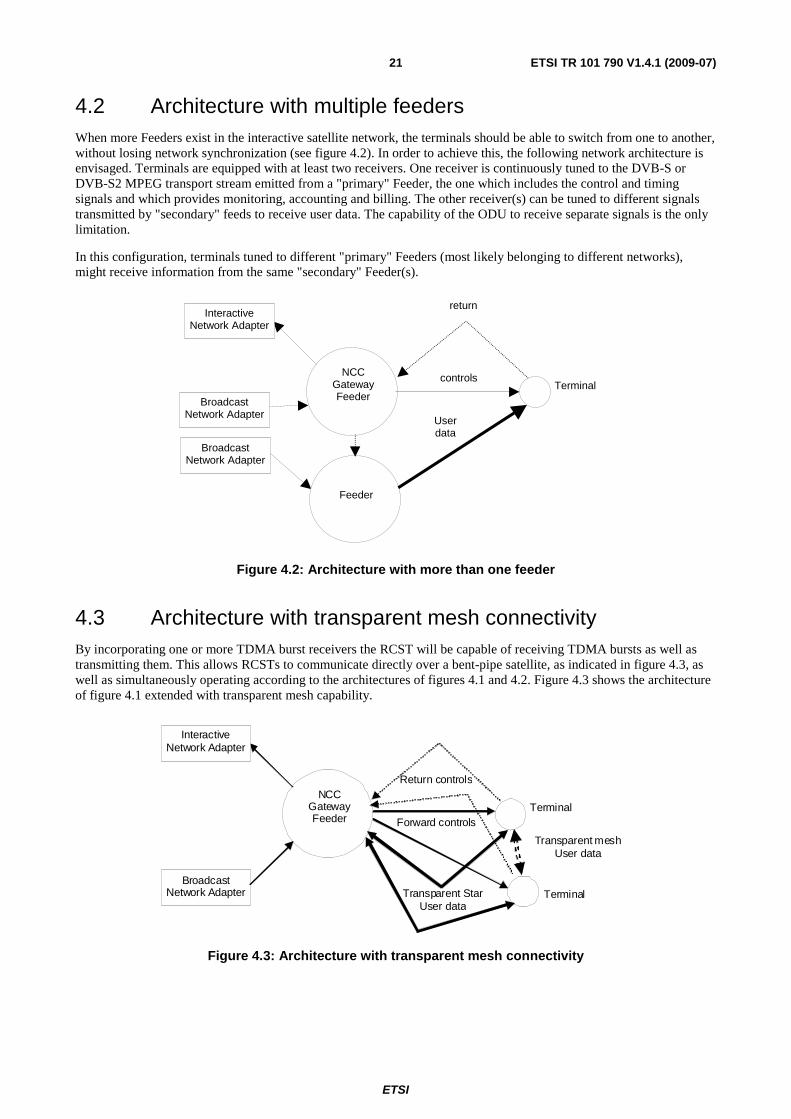
ETSI
ETSI TR 101 790 V1.4.1 (2009-07) 21
4.2 Architecture with multiple feeders When more Feeders exist in the interactive satellite network, the terminals should be able to switch from one to another, without losing network synchronization (see figure 4.2). In order to achieve this, the following network architecture is envisaged. Terminals are equipped with at least two receivers. One receiver is continuously tuned to the DVB-S or DVB-S2 MPEG transport stream emitted from a "primary" Feeder, the one which includes the control and timing signals and which provides monitoring, accounting and billing. The other receiver(s) can be tuned to different signals transmitted by "secondary" feeds to receive user data. The capability of the ODU to receive separate signals is the only limitation.
In this configuration, terminals tuned to different "primary" Feeders (most likely belonging to different networks), might receive information from the same "secondary" Feeder(s).
NCCGatewayFeeder
Terminalcontrols
Userdata
returnInteractive
Network Adapter
BroadcastNetwork Adapter
Feeder
BroadcastNetwork Adapter
Figure 4.2: Architecture with more than one feeder
4.3 Architecture with transparent mesh connectivity By incorporating one or more TDMA burst receivers the RCST will be capable of receiving TDMA bursts as well as transmitting them. This allows RCSTs to communicate directly over a bent-pipe satellite, as indicated in figure 4.3, as well as simultaneously operating according to the architectures of figures 4.1 and 4.2. Figure 4.3 shows the architecture of figure 4.1 extended with transparent mesh capability.
NCC Gateway Feeder
Terminal Forward controls
Transparent Star User data
Return controls
Interactive Network Adapter
Broadcast Network Adapter Terminal
Transparent mesh User data
Figure 4.3: Architecture with transparent mesh connectivity

ETSI
ETSI TR 101 790 V1.4.1 (2009-07) 22
4.4 Architecture with regenerative satellites The normative document [i.2] extends the standard to Regenerative Satellite Multimedia Systems (RSMS), i.e. systems in which the communications between NCC, Gateways, Feeders and terminals transit through a satellite with On-Board-Processing (OBP) functions (as opposed to a conventional, bent-pipe, satellite). This allows mesh connectivity to be established in the most efficient way. This is depicted in figure 4.3A.

ETSI
ETSI TR 101 790 V1.4.1 (2009-07) 23
NCC
Regenerative SAT
RSAT RSAT
NETWORK 1
GATEWAY 1STATION
NETWORK 2
InteractiveNetworkAdapter
RSATRSAT
GATEWAY 2STATION
InteractiveServiceProvider
Control Plane NCC- RSAT signalling
NCC- SAT signalling
InteractiveNetworkAdapter
InteractiveServiceProvider
NCC
Regenerative SAT
RSAT RSAT
NETWORK 1
GATEWAY 1STATION
NETWORK 2 InteractiveNetworkAdapter
RSATRSAT
GATEWAY 2STATION
InteractiveServiceProvider
Point- To - Multipoint (monodirectional)
Point-To-Point (bidirectional)
User Plane
RSAT RSATRSAT
Multipoint -To-Multipoint (bidirectional)
Point- To - Point (monodirectional)
InteractiveNetworkAdapter
Interactive
ServiceProvider
Figure 4.3A: Architecture with regenerative satellite
ETSI
ETSI TR 101 790 V1.4.1 (2009-07) 24
The Onboard Processors are classified as:
• Regenerative with onboard switching: This class of RSMS can in principle provide full traffic re-arrangement for point-to-point connections between terminals in a mesh network. The onboard processor can also be configured to support point-to-multipoint, multi-point-to-point connections and/or concentration /multicasting /broadcasting through flexible routing/switching between input and output ports.
• Regenerative without onboard switching: This class of RSMS is particularly attractive when the number of uplink and/or downlink beams is relatively small and the requirements for onboard traffic arrangement are moderate. In such cases the requirements for concentration and/or multicasting/ multiplexing type of connectivity prevail.
• Regenerative in conjunction with transparent repeater: This class of RSMS systems assumes a hybrid payload including both transparent and regenerative onboard switching repeaters. The terminals are connected to the RSMS network through the transparent repeater. Point-to-point connectivity between terminals is provided by the OBP Processor, hereafter called "mesh processor".
The functional requirements of the OBP processor are:
• Receive all traffic and control data sent by the terminals.
• Receive all traffic and control data sent by the NCC.
• Extract the traffic data to be sent on the downlink within DVB-S/S2 format and route them to the appropriate output(s) towards the receiving terminals.
• Generate/extract the control data to be sent to the NCC and route them to the appropriate output(s).
• Format downlink streams including all the necessary downlink signalling messages in DVB-RCS compatible DVB-S/S2 format and route/switch them to the appropriate output(s).
Different RSMS OBP implementations result from the apportionment of the MAC functions between onboard processor and on-ground entities; the RCS terminals and NCC. These are described in table 4.1.
Table 4.1: MAC Functions Partitioning in case of regenerative OBP satellite systems
MAC Function Network Entity Comments Data encapsulation /
de-capsulation OBP Onboard (not necessary if the MPEG2 profile
is used) Routing_Label Extraction
(SAC field) OBP Onboard, if applied for onboard
routing/switching. Not applicable in the case of regenerative without on board switching processor
Frame Format OBP Onboard (not necessary if DVB-RCS MPEG2 format is used)
Synchronization and power control
OBP/NCC On board measurements
NCR generation and insertion
OBP/NCC
Resource control and management
RCS (Capacity requests)/NCC/OBP
Performed on ground in case of Hybrid RSMS P/L with "mesh processor". Performed also on board in case Traffic manager is implemented on board
RCS configuration and management
NCC On ground
Logon NCC/OBP On board measurements Network Configuration Network Configuration On ground
ETSI
ETSI TR 101 790 V1.4.1 (2009-07) 25
4.4.1 On board switching requirements
RSMS require onboard routing or switching of signals between input and output ports. Different on board switching architectures can be used; circuit-switched, frame-switched, packet or cell switched architecture.
In case of RSMS performing packet or cell switching, there are two types of information identified as necessary to perform routing/switching:
• Addressing information to identify the destination RSAT; and
• Control (routing) information to the Onboard Processor (OBP) to perform routing/switching.
The increasing need of addressing and controlling/routing information is attributable to specific system design assumptions:
• The multi-beam coverage and the multi-port onboard switching matrix increase the number of possible routes.
• The support of multiple levels of Quality of Service.
• The multi-operator context: the inter-operability is increasing the routing possibilities and limits the reuse of the identifiers.
• The increasing number of simultaneous connections managed by a terminal (the number of customer premises equipment connected to this terminal).
In RSMS, the mesh traffic between terminals is only handled by the terminals but controlled, monitored and allocated by the NCC. There exists cases of regenerative satellite systems where the traffic manager functions are split between the NCC and the on board processor. In this latter case, the on board traffic manager plays an active role for the control, monitoring and allocation of resources to terminals.
4.4.2 RSMS Network Architecture
A RSMS network can be configured to support both star and mesh topologies based on DVB-RCS specification for the return channel and DVB-S/S2 specification for the forward channel.
As for a transparent satellite network, the regenerative satellite network in star topology supports access traffic to/from a gateway. In a regenerative architecture this star topology features some enhanced access network flexibility, such as interconnecting terminals to multiple gateways and/or multiplexing the star traffic with mesh traffic on a same given downlink carrier for the destination beam.
The Regenerative Satellite Network is characterized by the capability of star and mesh single-hop communications, and are composed of one or more beams. For multi-beam regenerative systems, cross-connectivity can be supported. The system includes the following network elements, as shown in figure 4.4:
• The On-Board Processor (OBP): uses a DVB-RCS air interface on the uplink (return link) and a DVB-S/S2 in the downlink (forward link), providing the modulation, coding and framing functions. Different architectures are possible, depending on the profile (MPEG or ATM), additional functions (multiplexing, table-switching, routing, etc.) or QoS support.
• RCST: interfaces user equipment with the satellite network and are able to communicate with other RCSTs or RSGWs.
• Management Station (MS): It is composed of several parts:
- Regenerative NCC, in charge of control plane functions for RCSTs and OBP configuration.
- Network Management Centre (NMC), which provides elements and network management.
- NCC-RCST (optional), supports modulation and demodulation functions, transmiting and receiving like a standard RCST.
• Regenerative Satellite Gateway (RSGW). This element is based on one or more RCSTs (called GW-RCSTs), a QoS module and the Adapters to connect to external networks (Internet, switching networks). Operated by the Interactive Service Provider, can provide IP (unicast and multicast) and telephony services.
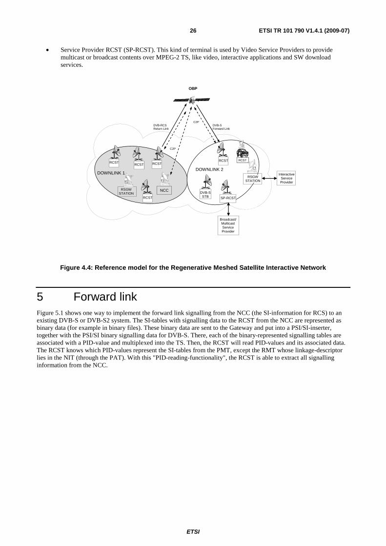
ETSI
ETSI TR 101 790 V1.4.1 (2009-07) 26
• Service Provider RCST (SP-RCST). This kind of terminal is used by Video Service Providers to provide multicast or broadcast contents over MPEG-2 TS, like video, interactive applications and SW download services.
NETWORK 2
NCC
DOWNLINK 1 DOWNLINK 2
RCST
RCST
RCST
DVB-S STB
RSGW STATION
RCST
DVB-RCS Return Link
C2P
DVB-S Forward Link
C2P
OBP
RCST
RSGW STATION
Interactive Service Provider
SP-RCST
Broadcast/ Multicast Service Provider
RCST
Figure 4.4: Reference model for the Regenerative Meshed Satellite Interactive Network
5 Forward link Figure 5.1 shows one way to implement the forward link signalling from the NCC (the SI-information for RCS) to an existing DVB-S or DVB-S2 system. The SI-tables with signalling data to the RCST from the NCC are represented as binary data (for example in binary files). These binary data are sent to the Gateway and put into a PSI/SI-inserter, together with the PSI/SI binary signalling data for DVB-S. There, each of the binary-represented signalling tables are associated with a PID-value and multiplexed into the TS. Then, the RCST will read PID-values and its associated data. The RCST knows which PID-values represent the SI-tables from the PMT, except the RMT whose linkage-descriptor lies in the NIT (through the PAT). With this "PID-reading-functionality", the RCST is able to extract all signalling information from the NCC.

ETSI
ETSI TR 101 790 V1.4.1 (2009-07) 27
MODMUXPSI/SI
Inserter
audio, video, data etc.
DVB-Sor
DVB-S2link
RCST
PSI/SI
Network Control Center (NCC)
SI forRCS
Gateway
ISP
Figure 5.1: Implementation of SI signalling from NCC in DVB-S or DVB-S2
5.1 Assignment and selection of FL elementary streams An NCC may assume that the RCST automatically receives MPE elementary streams (of the stream type 0x0D and applying table_id 0x3E) that are listed in the feeder FL service specification given in the PMT. It is recommended that the RCST automatically starts receiving MPE traffic from these elementary streams as part of the forward link acquisition, or at the latest at the time of logon. The NCC cannot be expected to explicitly indicate assignment of these elementary streams for each RCST, e.g. by the FIP descriptor, but may do so as well.
The NCC may assign multiple simultaneous MPE elementary streams to an RCST. The RCST is then expected to be capable of receiving the MPE traffic from all the assigned elementary streams. Different RCST implementations may have different limitations in the number of MPE elementary streams that can be received simultaneously. This should be considered when commissioning commonly assigned elementary streams and individually assigned elementary streams.
An RCST may have a limitation in the maximum aggregate rate of MPE encapsulated traffic in elementary streams that the RCST can handle, compared to the gross rate of such traffic that the feeder TS can hold. Such an RCST should only be assigned MPE elementary streams that aggregated do not exceed the instantaneous MPE rate limit of the RCST.
An NCC may apply several methods for assigning MPE elementary streams to an RCST in addition to listing them in the PMT. FL MPE elementary streams can be assigned to an RCST by PID reference in the Forward Interaction Path (FIP) descriptor or by any other assignment method. The RCST should assume that an elementary stream assigned by FIP or other methods contains natively encapsulated IP traffic in the MPE format (table_id 0x3E), unless the specific elementary stream is explicitly known to have other content through system dependent methods.

ETSI
ETSI TR 101 790 V1.4.1 (2009-07) 28
5.2 Specific use of FL tables and formats
5.2.1 FL service specification in PMT
It is recommended that the NCC uses stream type 0x05 (stream with private sections according to [i.50]) for declaration of an elementary stream that carries any of the RCS C&M tables, TIM as well. Elementary streams of user defined stream types may not be recognized by an RCST, even if the RCS content descriptor is applied. It is recommended that the RCST ignores elementary streams that are declared with unrecognized stream types.
The RCS content descriptor is according to [i.2] applicable for localizing the RCS specified C&M tables except for the RMT declaration being optional. Declaration is in principle optional for content not specified in RCS, like MPE. It is recommended that each elementary stream of the FL service specification is declared with an RCS content descriptor listing all RCS applicable table IDs that occur in the specific elementary stream, MPE as well. When used in the FL service specification of an elementary stream, the RCS content descriptor should contain an exhaustive list of all the table types that an RCST is assumed to receive from that specific elementary stream.
It may however be that an elementary stream carrying MPE is not declared through an RCS content descriptor but only through the stream type, thus an RCST should be capable of detecting such an elementary stream based on stream type 0x0D only, and should for this stream type assume an implicit RCS content descriptor declaration with the table_id 0x3E.
Note that it should not be expected that an RCST discriminates a specific table type from a specific elementary stream even if this table type is not declared in the RCS descriptor for that specific elementary stream or a received table type is incompatible with the declared stream type. The RCS content descriptor and the stream type can only be expected to function as locators for deciding to receive a specific elementary stream, and not as runtime discriminators of tables. Thus, none of the elementary streams assigned to an RCST should contain any RCS incompatible table using a table id from the set applicable for an RCST.
5.2.1 Optional use of SDT
An SDT can contain one or more data_broadcast_descriptors that indicates characteristics of MPE as applied by the feeder. SDT is considered optional by [i.2]. An RCST should thus not rely on receiving the data_broadcast_descriptor. It should not be expected that RCST implementations follow specific configurations given in the SDT.
5.2.2 Assumptions concerning IP encapsulation
It is recommended that a feeder system applies native IP encapsulation in MPE. Alternative formats for IP encapsulation, e.g. like ATM based data piping as specified by [i.2] and LLC/SNAP based encapsulation in MPE as specified by [i.34] should only be applied by the feeder if specifically known to be supported by the addressed RCSTs.
It is recommended that a feeder system does not apply table_id 0x3E for other content than MPE. Other usage of DSM-CC private data as allowed by [i.51] should not occur in the associated elementary streams due to the risk of ambiguities. A feeder system should not indicate stream type 0x0D for the FL service elementary streams for other elementary streams than those used to transport MPE.
The RCST can expect a full 48 bit MAC address in the MPE format. A feeder may or may not issue one or more data_broadcast_descriptors for the FL service. RCSTs that do not receive an associated data_broadcast_descriptor are recommended to apply the values listed in table 5.1. FL MPE elementary streams assigned by other means than through the association with the FL service specification in the PMT should be assumed to conform to the values listed in table 5.2.
Table 5.2: Recommended implicit parameter values to be assumed by an RCST when the data_broadcast_descriptor is not received
Parameter Value Meaning MAC_address_range 0x06 There are 48 significant bits MAC_IP_mapping_flag 1 Multicast addressing follows RFC 1112 [i.22] alignment_indicator 0 There is 8 bit alignment max_sections_per_datagram 1 There is a size limit of 4084 bytes for the IP packet
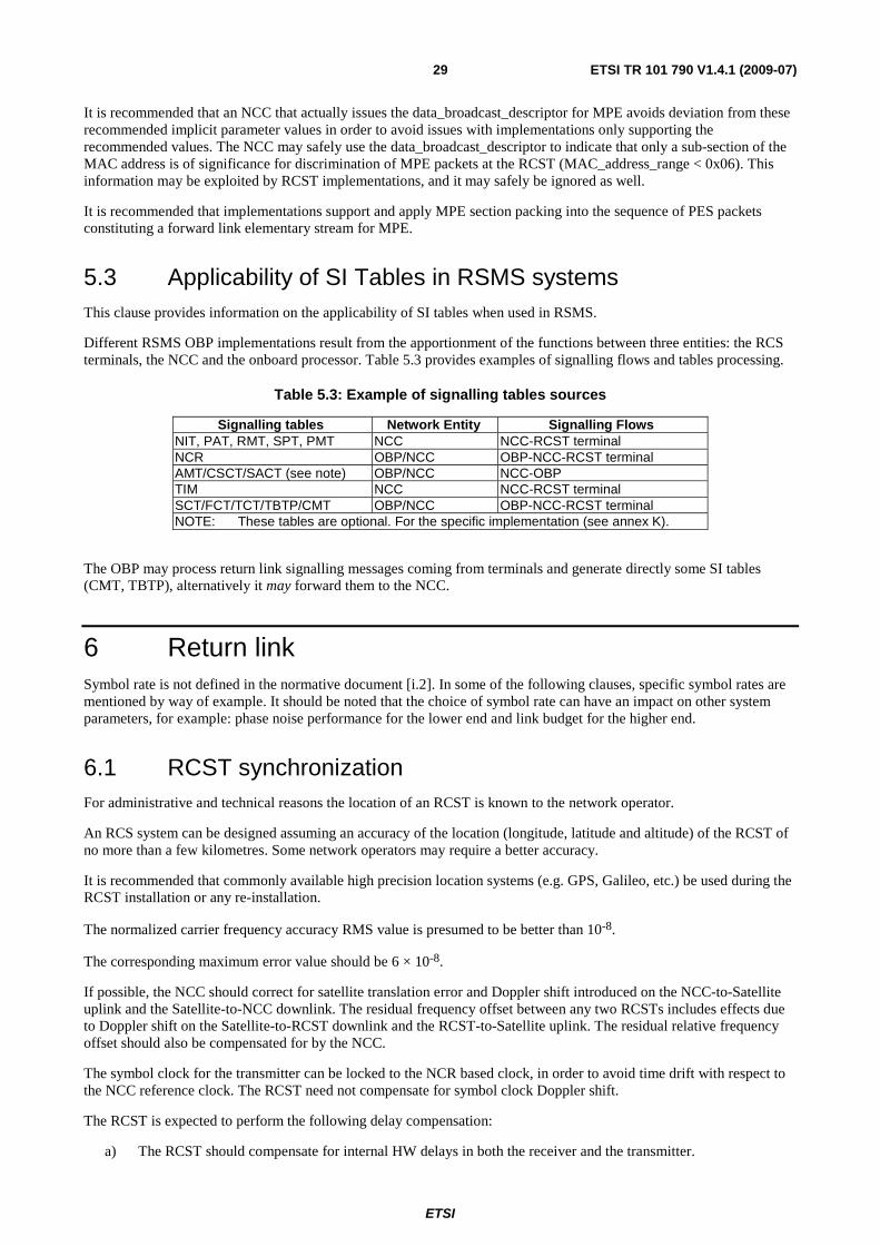
ETSI
ETSI TR 101 790 V1.4.1 (2009-07) 29
It is recommended that an NCC that actually issues the data_broadcast_descriptor for MPE avoids deviation from these recommended implicit parameter values in order to avoid issues with implementations only supporting the recommended values. The NCC may safely use the data_broadcast_descriptor to indicate that only a sub-section of the MAC address is of significance for discrimination of MPE packets at the RCST (MAC_address_range < 0x06). This information may be exploited by RCST implementations, and it may safely be ignored as well.
It is recommended that implementations support and apply MPE section packing into the sequence of PES packets constituting a forward link elementary stream for MPE.
5.3 Applicability of SI Tables in RSMS systems This clause provides information on the applicability of SI tables when used in RSMS.
Different RSMS OBP implementations result from the apportionment of the functions between three entities: the RCS terminals, the NCC and the onboard processor. Table 5.3 provides examples of signalling flows and tables processing.
Table 5.3: Example of signalling tables sources
Signalling tables Network Entity Signalling Flows NIT, PAT, RMT, SPT, PMT NCC NCC-RCST terminal NCR OBP/NCC OBP-NCC-RCST terminal AMT/CSCT/SACT (see note) OBP/NCC NCC-OBP TIM NCC NCC-RCST terminal SCT/FCT/TCT/TBTP/CMT OBP/NCC OBP-NCC-RCST terminal NOTE: These tables are optional. For the specific implementation (see annex K).
The OBP may process return link signalling messages coming from terminals and generate directly some SI tables (CMT, TBTP), alternatively it may forward them to the NCC.
6 Return link Symbol rate is not defined in the normative document [i.2]. In some of the following clauses, specific symbol rates are mentioned by way of example. It should be noted that the choice of symbol rate can have an impact on other system parameters, for example: phase noise performance for the lower end and link budget for the higher end.
6.1 RCST synchronization For administrative and technical reasons the location of an RCST is known to the network operator.
An RCS system can be designed assuming an accuracy of the location (longitude, latitude and altitude) of the RCST of no more than a few kilometres. Some network operators may require a better accuracy.
It is recommended that commonly available high precision location systems (e.g. GPS, Galileo, etc.) be used during the RCST installation or any re-installation.
The normalized carrier frequency accuracy RMS value is presumed to be better than 10-8.
The corresponding maximum error value should be 6 × 10⁻⁸.
If possible, the NCC should correct for satellite translation error and Doppler shift introduced on the NCC-to-Satellite uplink and the Satellite-to-NCC downlink. The residual frequency offset between any two RCSTs includes effects due to Doppler shift on the Satellite-to-RCST downlink and the RCST-to-Satellite uplink. The residual relative frequency offset should also be compensated for by the NCC.
The symbol clock for the transmitter can be locked to the NCR based clock, in order to avoid time drift with respect to the NCC reference clock. The RCST need not compensate for symbol clock Doppler shift.
The RCST is expected to perform the following delay compensation:
a) The RCST should compensate for internal HW delays in both the receiver and the transmitter.
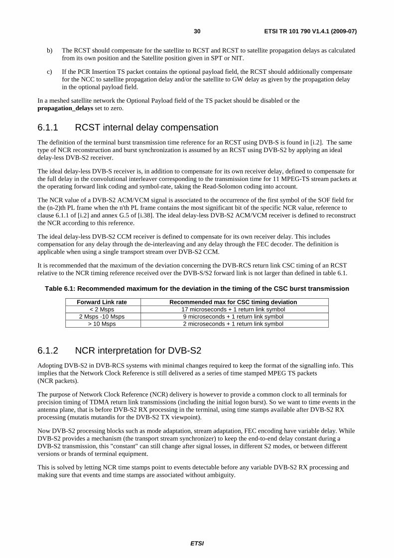
ETSI
ETSI TR 101 790 V1.4.1 (2009-07) 30
b) The RCST should compensate for the satellite to RCST and RCST to satellite propagation delays as calculated from its own position and the Satellite position given in SPT or NIT.
c) If the PCR Insertion TS packet contains the optional payload field, the RCST should additionally compensate for the NCC to satellite propagation delay and/or the satellite to GW delay as given by the propagation delay in the optional payload field.
In a meshed satellite network the Optional Payload field of the TS packet should be disabled or the propagation_delays set to zero.
6.1.1 RCST internal delay compensation
The definition of the terminal burst transmission time reference for an RCST using DVB-S is found in [i.2]. The same type of NCR reconstruction and burst synchronization is assumed by an RCST using DVB-S2 by applying an ideal delay-less DVB-S2 receiver.
The ideal delay-less DVB-S receiver is, in addition to compensate for its own receiver delay, defined to compensate for the full delay in the convolutional interleaver corresponding to the transmission time for 11 MPEG-TS stream packets at the operating forward link coding and symbol-rate, taking the Read-Solomon coding into account.
The NCR value of a DVB-S2 ACM/VCM signal is associated to the occurrence of the first symbol of the SOF field for the (n-2)th PL frame when the n'th PL frame contains the most significant bit of the specific NCR value, reference to clause 6.1.1 of [i.2] and annex G.5 of [i.38]. The ideal delay-less DVB-S2 ACM/VCM receiver is defined to reconstruct the NCR according to this reference.
The ideal delay-less DVB-S2 CCM receiver is defined to compensate for its own receiver delay. This includes compensation for any delay through the de-interleaving and any delay through the FEC decoder. The definition is applicable when using a single transport stream over DVB-S2 CCM.
It is recommended that the maximum of the deviation concerning the DVB-RCS return link CSC timing of an RCST relative to the NCR timing reference received over the DVB-S/S2 forward link is not larger than defined in table 6.1.
Table 6.1: Recommended maximum for the deviation in the timing of the CSC burst transmission
Forward Link rate Recommended max for CSC timing deviation < 2 Msps 17 microseconds + 1 return link symbol
2 Msps -10 Msps 9 microseconds + 1 return link symbol > 10 Msps 2 microseconds + 1 return link symbol
6.1.2 NCR interpretation for DVB-S2
Adopting DVB-S2 in DVB-RCS systems with minimal changes required to keep the format of the signalling info. This implies that the Network Clock Reference is still delivered as a series of time stamped MPEG TS packets (NCR packets).
The purpose of Network Clock Reference (NCR) delivery is however to provide a common clock to all terminals for precision timing of TDMA return link transmissions (including the initial logon burst). So we want to time events in the antenna plane, that is before DVB-S2 RX processing in the terminal, using time stamps available after DVB-S2 RX processing (mutatis mutandis for the DVB-S2 TX viewpoint).
Now DVB-S2 processing blocks such as mode adaptation, stream adaptation, FEC encoding have variable delay. While DVB-S2 provides a mechanism (the transport stream synchronizer) to keep the end-to-end delay constant during a DVB-S2 transmission, this "constant" can still change after signal losses, in different S2 modes, or between different versions or brands of terminal equipment.
This is solved by letting NCR time stamps point to events detectable before any variable DVB-S2 RX processing and making sure that events and time stamps are associated without ambiguity.
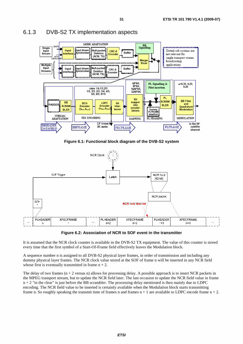
ETSI
ETSI TR 101 790 V1.4.1 (2009-07) 31
6.1.3 DVB-S2 TX implementation aspects
Figure 6.1: Functional block diagram of the DVB-S2 system
...
PLHEADER
n
PLHEADER
n+3
XFECFRAME
n+2
XFECFRAME
n+3
XFECFRAME
n
LatchSOF Trigger
7 56
1211
10
8 4
21
9 3NCR Clock
NCR field
(42-bit)
NCR packet
NCR field first bitSOF
n
PLHEADER
n+2... ...
Figure 6.2: Association of NCR to SOF event in the transmitter
It is assumed that the NCR clock counter is available in the DVB-S2 TX equipment. The value of this counter is stored every time that the first symbol of a Start-Of-Frame field effectively leaves the Modulation block.
A sequence number n is assigned to all DVB-S2 physical layer frames, in order of transmission and including any dummy physical layer frames. The NCR clock value stored at the SOF of frame n will be inserted in any NCR field whose first is eventually transmitted in frame n + 2.
The delay of two frames (n + 2 versus n) allows for processing delay. A possible approach is to insert NCR packets in the MPEG transport stream, but to update the NCR field later. The last occasion to update the NCR field value in frame n + 2 "in the clear" is just before the BB scrambler. The processing delay mentioned is then mainly due to LDPC encoding. The NCR field value to be inserted is certainly available when the Modulation block starts transmitting frame n. So roughly speaking the transmit time of frames n and frames n + 1 are available to LDPC encode frame n + 2.
ETSI
ETSI TR 101 790 V1.4.1 (2009-07) 32
The most stringent requirement on LDPC encoder speed then typically corresponds to the following combination of elements:
• high symbol rate;
• for frames n, n + 1: short block size, high order modulation (32APSK);
• for frame n + 2: long block size, high code rate (9/10).
6.1.4 DVB-S2 RX implementation aspects
The main requirement is to associate without ambiguity detected SOF with decoded frames (and hence with NCR fields within the frame), and to make this information available to the NCR synchronization circuit in the terminal. Decoding processing delays are far less critical.
An association and interfacing approach that puts almost no functional requirements on the DVB-S2 RX chip is outlined in DVB-S2 Specifications, annex G5 [i.38]. Here DVB-RCS specific functions are also separated maximally from DVB-S2 functions.
Decoding delay jitter does not degrade the network clock reference extracted by the terminal. It is important however to verify that SOF detect circuit has low jitter. (Typical requirement, depending on NCR tracking design: SOF detect jitter < 100 ns-pp).
It is recommended that systematic delays in the SOF detect circuit (for example the delay of the RX filter) are documented by the DVB-S2 RX circuit provider. These delays can then be compensated for in the RCS terminal design, if needed.
It is also recommended to prevent that data flagged as unreliable enter the NCR tracking circuit. Unreliable data flags can originate from in a DVB-S2 receiver from BB header checking, BCH decoding checks, TS packet CRC check.
6.1.5 VCM/ACM aspects and Multiple TS aspects
Typically the highest protection level in use in the system is applied to the forward link signalling.
Typically the mode adaptation block is configured to send signalling info with sufficiently high priority and therefore, to maintain more or less constant NCR intervals.
In general (also with single TS!) NCR fields can be fragmented and sent in two different DVB-S2 frames. In case of multiple TS these two frames need not be consecutive.
They will still be consecutive within the TS ID of the TS carrying the NCR, but frames belonging to other TS ID may come in-between.
6.1.6 Combining TS and GS
When GS and TS are combined, the non-IP based RCS signaling will be transported in the TS. Generic Stream Encapsulation (GSE) as specified in [i.57] is recommended as the encapsulation for IP in the GS.
ETSI
ETSI TR 101 790 V1.4.1 (2009-07) 33
6.2 Burst format
6.2.1 Contention access
Multiple access on traffic slots is based on a reservation mechanism, in which traffic slots are uniquely assigned to the requested RCST through the use of the RCST's Group_ID and Logon_ID. The Network determines the originator of the bursts transmitted in these allocated slots through the knowledge of the TBTP. However, the Network may also advertise contention access on particular traffic slots, using the same mechanism as that defined in [i.2] for the SYNC slots; that is, by assigning the reserved Logon_ID = 0xFFFF to these traffic slots. In this case, the Network will make use of the SAC prefix method for the ATM profile in order to identify the transmitter of the burst arriving in contention-based traffic slots. For the MPEG profile, because the prefix SAC is not defined, assignment of PIDs to terminals or other privately defined mechanisms may be used for the same purpose. It should be noted that the throughput of contention-based access is generally lower than that of reservation-based access, and that high delay variations could occur with contention-based access during congestion periods.
Clause 6.12 gives further clarifications on contention access on SYNC slots; the mechanisms for ATM and MPEG2-based traffic slots are explained further by means of examples in clauses 6.7.1.1 and 6.7.1.2, respectively.
It is recommended that sync slots are formed by subdivision of traffic slots. For example, in the single ATM cell sized slot, this slot can be divided into 2 or more sync slots.
All SYNC slots assigned to the RCSTs will be used for transmitting SYNC bursts. If the terminal does not have a message to send, it will use the "No message" in the M&C sub-field. If the terminal does not have any capacity request to send, it will send a VBDC request with an amount of 0.
6.2.2 Acquisition Bursts
The fixed symbol pattern transmitted in ACQ bursts is referred to as a "frequency sequence", because of its common use for determining and correcting the transmit frequency. An example for the "frequency sequence" in the transmission of an ACQ slot could have the format as: B79A A5B7 625D F39F 8A07 09E8 AE86 F1FA E063 045B 9125 AA61 2.
Example values for the preamble are given in table 6.1.
Table 6.1: Example preamble values
Preamble_length Example preamble (hexadecimal notation, msb sent first, gray-coded mapping)
32 0347 F657 1528 E590 48 67FC 8EE8 A8D3 F6CB 4612 B784
Both the preamble and frequency sequences are provided to the RCSTs in the forward link tables (TCT). For the ACQ bursts, the data signalled in the TCT is the concatenation of the preamble and frequency sequence.
6.2.3 Determination of the implicit number of MPEG2 packets in a burst
When using the optional MPEG2 traffic bursts, the number of packets is implicitly given in the TCT. The RCSTs can apply the following procedure to find this number.
1) Step1: Convert timeslot_duration (tsd) and burst_start_offset (bso) from upcrmsf into uimsbf:
• An n-bit τ of PCR counts in upcrmsf is converted to uimsbf by:
- δ(τ) (uimbsf) = base(τ ) × 300 + ext(τ ).
- Where ext(τ) is the uimbsf defined by the 9 least significant bits of τ and base(τ) is the uimsbf defined by the (n-9) most significant bits.
2) Step 2: Convert δ(tsd) and δ(bso) from PCR counts to modulation symbols:
• A duration of δ PCR counts is converted into (uimsbf) modulation symbols by:
ETSI
ETSI TR 101 790 V1.4.1 (2009-07) 34
- d(δ) (uimsbf) symbols = δ PCR counts × symbol_rate/27 000 000.
3) Step 3: Compute the number of channel bits of one encoded packet and divide it by 2 to get (uimsbf) modulation symbols (QPSK assumed).
4) Step 4: The number of packets in the time slot is:
• Number of packets = Ψ [ (d(tsd) - d(bso) - d(preamble) )/ d(one encoded packet) ].
- Where Ψ[.] is the integer operator.
This method supposes that the guard time of an MPEG TRF burst is shorter than one half MPEG2 TS packet.
6.2.4 Application of MPE in the return link
The MPE MAC address content for the return link is undefined by [i.2], and implementations cannot be expected to put specific information into the MAC address field. The content of the MPE MAC address field is generally recommended discarded at the GW.
The use of 8 bit alignment of encapsulated IP information is recommended.
As for the forward link, it is recommended to not extend IP packets over several MPE sections, limiting the IP packet size to the single MPE section MTU of 4 084 bytes. However, GW designs may rely on Ethernet when forwarding IP traffic, and a burst receiver that reassembles IP may not itself be capable of fragmenting IP. The MTU for the return link is thus recommended limited to 1 500 bytes by the RCST, see [i.54] for the transport of IP over Ethernet.
It is recommended that an RCST supports and applies MPE section packing into each sequence of elementary stream packets identified by a common PID value.
6.3 Randomization for energy dispersal A complementary non self-synchronizing de-randomizer is used in the receiver to recover the data randomized as described in EN 301 790 [i.2]. The de-randomizer is enabled after detection of the preamble.
6.4 Coding When the ATM profile is used, the payload of each burst always constitutes a single code word, independently of the payload size and the type of coding (concatenated RS/convolutional or Turbo). In contrast, when the optional MPEG profile is used, each MPEG-TS packet is encoded as a separate codeword.
6.4.1 CRC error detection code
As stated in EN 301 790 [i.2], the CRC code is mandatory on turbo coded CSC bursts.
6.4.1.1 CRC coding example
CRC coding of a CSC burst is taken as an example. The clear, randomized and CRC coded sequences are listed in table 6.2 from left to right in order of transmission, in hexadecimal format, with msb sent first. CRC coding is applied after randomization.
Since EN 301 790 [i.2] defines CRC computation as a polynomial division, the CRC encoder register is set to initial value 0x0000 before processing the first bit (0) of the first byte 0x43 of the randomized sequence. Finally, after processing the last bit (0) of the last byte 0xd6 the CRC encoder register content becomes 0x2f6d. In the absence of errors, the decoder CRC register content becomes 0x0000 after processing the complete burst inclusive CRC bits.
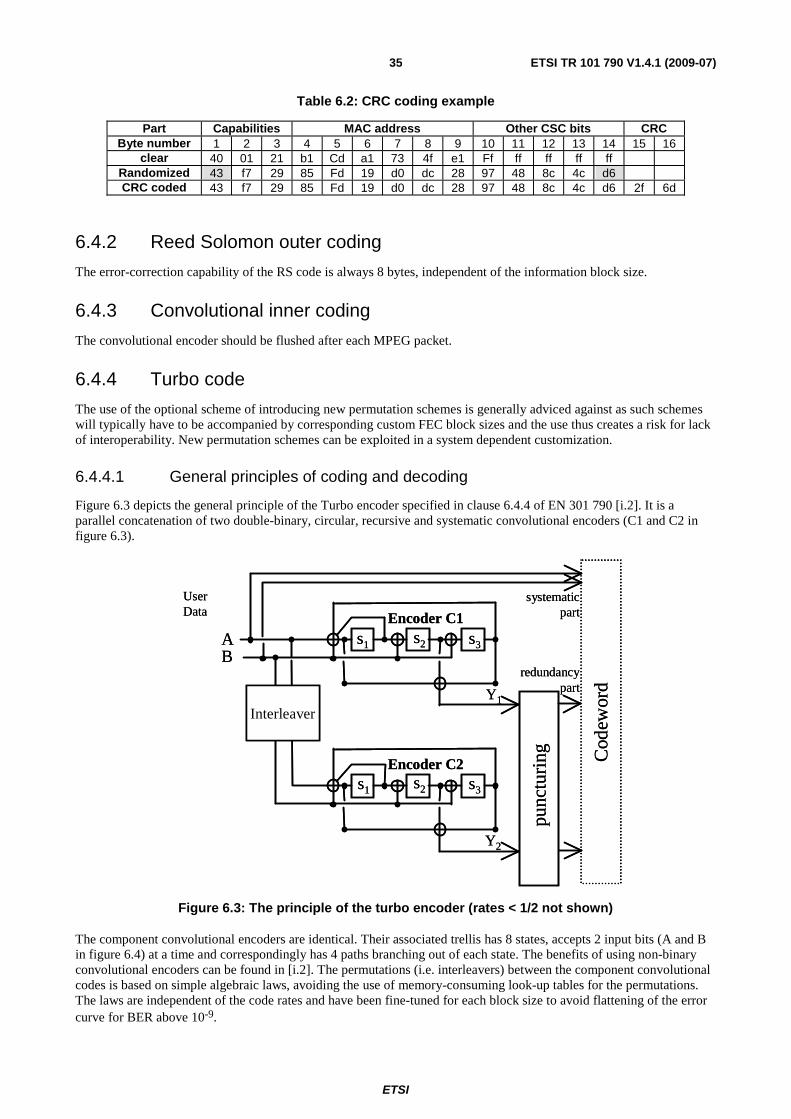
ETSI
ETSI TR 101 790 V1.4.1 (2009-07) 35
Table 6.2: CRC coding example
Part Capabilities MAC address Other CSC bits CRC Byte number 1 2 3 4 5 6 7 8 9 10 11 12 13 14 15 16
clear 40 01 21 b1 Cd a1 73 4f e1 Ff ff ff ff ff Randomized 43 f7 29 85 Fd 19 d0 dc 28 97 48 8c 4c d6 CRC coded 43 f7 29 85 Fd 19 d0 dc 28 97 48 8c 4c d6 2f 6d
6.4.2 Reed Solomon outer coding
The error-correction capability of the RS code is always 8 bytes, independent of the information block size.
6.4.3 Convolutional inner coding
The convolutional encoder should be flushed after each MPEG packet.
6.4.4 Turbo code
The use of the optional scheme of introducing new permutation schemes is generally adviced against as such schemes will typically have to be accompanied by corresponding custom FEC block sizes and the use thus creates a risk for lack of interoperability. New permutation schemes can be exploited in a system dependent customization.
6.4.4.1 General principles of coding and decoding
Figure 6.3 depicts the general principle of the Turbo encoder specified in clause 6.4.4 of EN 301 790 [i.2]. It is a parallel concatenation of two double-binary, circular, recursive and systematic convolutional encoders (C1 and C2 in figure 6.3).
AB
s1
Encoder C1
Encoder C2
Interleaver
punc
turi
ng Cod
ewor
dsystematic
part
redundancypart
UserData
Y1
Y2
s1 s2
s2 s3
s3
AB
s1
Encoder C1
Encoder C2
Interleaver
punc
turi
ng Cod
ewor
dsystematic
part
redundancypart
UserData
Y1
Y2
s1 s2
s2 s3
s3
Figure 6.3: The principle of the turbo encoder (rates < 1/2 not shown)
The component convolutional encoders are identical. Their associated trellis has 8 states, accepts 2 input bits (A and B in figure 6.4) at a time and correspondingly has 4 paths branching out of each state. The benefits of using non-binary convolutional encoders can be found in [i.2]. The permutations (i.e. interleavers) between the component convolutional codes is based on simple algebraic laws, avoiding the use of memory-consuming look-up tables for the permutations. The laws are independent of the code rates and have been fine-tuned for each block size to avoid flattening of the error curve for BER above 10-9.
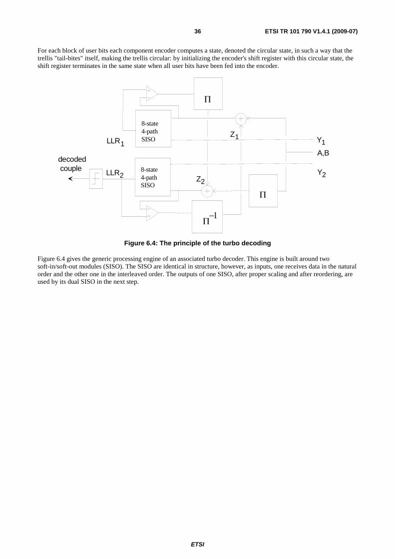
ETSI
ETSI TR 101 790 V1.4.1 (2009-07) 36
For each block of user bits each component encoder computes a state, denoted the circular state, in such a way that the trellis "tail-bites" itself, making the trellis circular: by initializing the encoder's shift register with this circular state, the shift register terminates in the same state when all user bits have been fed into the encoder.
decoded couple
Y1
LLR
LLR 1
2
Z1
Z2
A,B
8-state4-pathSISO
8-state4-pathSISO
Π
Π
Π−1
Y2
Figure 6.4: The principle of the turbo decoding
Figure 6.4 gives the generic processing engine of an associated turbo decoder. This engine is built around two soft-in/soft-out modules (SISO). The SISO are identical in structure, however, as inputs, one receives data in the natural order and the other one in the interleaved order. The outputs of one SISO, after proper scaling and after reordering, are used by its dual SISO in the next step.

ETSI
ETSI TR 101 790 V1.4.1 (2009-07) 37
6.4.4.2 Puncturing examples for DVB-RCS Turbo Code
Figures 6.4a and 6.4b illustrate the puncturing process for the Turbo code.
A
Y1
B
W1
A
Y1
BA
Y1
BA
Y1
BAB
A
Y1
BA
Y1
BA
Y1
BY1
iAB
A
Y1
BA
Y1
BA
Y1
BY1
N-1N-2N-3N-40 4321 65 7
A
Y2
B
W2
AB
AB
AB
AB
AB
AB
AB
jAB
AB
AB
AB
N-1N-2N-3N-40 4321 65 7
W2 W2 W2 W2 W2 W2 W2
R=1/3
R=2/5 (0,4)
C1
C2
W1W1W1W1 W1W1W1 W1 W1W1W1
Y2Y2Y2Y2Y2 Y2Y2 Y2Y2Y2Y2
W2W2W2W2
A
Y1
B
W1
A
Y1
BA
Y1
BA
Y1
BAB
A
Y1
BA
Y1
BA
Y1
BY1
iAB
A
Y1
BA
Y1
BA
Y1
BY1
N-1N-2N-3N-40 4321 65 7
A
Y2
B
W2
AB
AB
AB
AB
AB
AB
AB
jAB
AB
AB
AB
N-1N-2N-3N-40 4321 65 7
W2 W2 W2 W2 W2 W2 W2
C1
C2
W1W1W1W1 W1W1W1 W1 W1W1W1
Y2Y2Y2Y2Y2 Y2Y2 Y2Y2Y2Y2
W2W2W2W2
R=1/2
A
Y1
B
W1
A
Y1
BA
Y1
BA
Y1
BAB
A
Y1
BA
Y1
BA
Y1
BY1
iAB
A
Y1
BA
Y1
BA
Y1
BY1
N-1N-2N-3N-40 4321 65 7
A
Y2
B
W2
AB
AB
AB
AB
AB
AB
AB
jAB
AB
AB
AB
N-1N-2N-3N-40 4321 65 7
W2 W2 W2 W2 W2 W2 W2
C1
C2
W1W1W1W1 W1W1W1 W1 W1W1W1
Y2Y2Y2Y2Y2 Y2Y2 Y2Y2Y2Y2
W2W2W2W2
Figure 6.4a: Puncturing process for low code rates
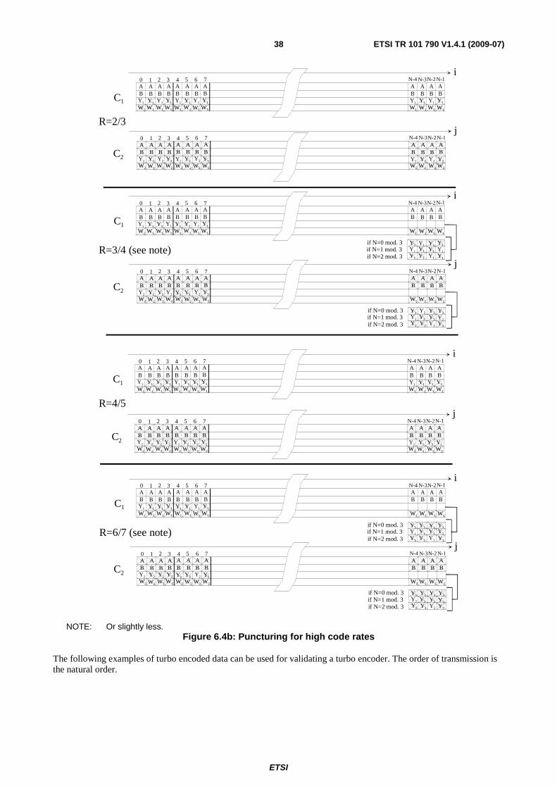
ETSI
ETSI TR 101 790 V1.4.1 (2009-07) 38
R=2/3
A
Y1
B
W1
A
Y1
BA
Y1
BA
Y1
BAB
A
Y1
BA
Y1
BA
Y1
BY1
iAB
A
Y1
BA
Y1
BA
Y1
BY1
N-1N-2N-3N-40 4321 65 7
A
Y2
B
W2
AB
AB
AB
AB
AB
AB
AB
jAB
AB
AB
AB
N-1N-2N-3N-40 4321 65 7
W2 W2 W2 W2 W2 W2 W2
C1
C2
W1W1W1W1 W1W1W1 W1 W1W1W1
Y2Y2Y2Y2Y2 Y2Y2 Y2Y2Y2Y2
W2W2W2W2
R=3/4 (see note)
A
Y1
B
W1
A
Y1
BA
Y1
BA
Y1
BAB
A
Y1
BA
Y1
BA
Y1
BY1
iAB
AB
AB
AB
N-1N-2N-3N-40 4321 65 7
A
Y2
B
W2
AB
AB
AB
AB
AB
AB
AB
jAB
AB
AB
AB
N-1N-2N-3N-40 4321 65 7
W2 W2 W2 W2 W2 W2 W2
C1
C2
W1W1W1W1 W1W1W1 W1 W1W1W1
Y2Y2Y2Y2Y2 Y2Y2
W2W2W2W2
R=4/5
A
Y1
B
W1
A
Y1
BA
Y1
BA
Y1
BAB
A
Y1
BA
Y1
BA
Y1
BY1
iAB
A
Y1
BA
Y1
BA
Y1
BY1
N-1N-2N-3N-40 4321 65 7
A
Y2
B
W2
AB
AB
AB
AB
AB
AB
AB
jAB
AB
AB
AB
N-1N-2N-3N-40 4321 65 7
W2 W2 W2 W2 W2 W2 W2
C1
C2
W1W1W1W1 W1W1W1 W1 W1W1W1
Y2Y2Y2Y2Y2 Y2Y2 Y2Y2Y2Y2
W2W2W2W2
Y1
Y1
Y1
Y1
Y1
Y1
Y1
Y1
Y1
Y1
Y1
Y1if N=0 mod. 3
if N=2 mod. 3if N=1 mod. 3
Y2if N=0 mod. 3
if N=2 mod. 3if N=1 mod. 3
Y2
Y2Y2Y2
Y2
Y2Y2Y2
Y2
Y2Y2
R=6/7 (see note)
A
Y1
B
W1
A
Y1
BA
Y1
BA
Y1
BAB
A
Y1
BA
Y1
BA
Y1
BY1
iAB
AB
AB
AB
N-1N-2N-3N-40 4321 65 7
A
Y2
B
W2
AB
AB
AB
AB
AB
AB
AB
jAB
AB
AB
AB
N-1N-2N-3N-40 4321 65 7
W2 W2 W2 W2 W2 W2 W2
C1
C2
W1W1W1W1 W1W1W1 W1 W1W1W1
Y2Y2Y2Y2Y2 Y2Y2
W2W2W2W2
Y1
Y1
Y1
Y1
Y1
Y1
Y1
Y1
Y1
Y1
Y1
Y1if N=0 mod. 3
if N=2 mod. 3if N=1 mod. 3
Y2if N=0 mod. 3
if N=2 mod. 3if N=1 mod. 3
Y2
Y2Y2Y2
Y2
Y2Y2Y2
Y2
Y2Y2
NOTE: Or slightly less. Figure 6.4b: Puncturing for high code rates
The following examples of turbo encoded data can be used for validating a turbo encoder. The order of transmission is the natural order.

ETSI
ETSI TR 101 790 V1.4.1 (2009-07) 39
The 16-byte packet to be encoded (payload data) is formed by the repetition of the h87 byte:
Bit 0 1 2 3 4 5 6 7 A0 B0 A1 B1 A2 B2 A3 B3 H87 = 1 0 0 0 0 1 1 1
1) Payload data sequence (A0B0 A1B1 …….A63B63):
10 00 01 11 10 00 01 11 10 00 01 11 10 00 01 11 10 00 01 11 10 00 01 11 10 00 01 11 10 00 01 11 10 00 01 11 10 00 01 11 10 00 01 11 10 00 01 11 10 00 01 11 10 00 01 11 10 00 01 11 10 00 01 11
2) Rate 1/3:
"Y" parity sequence (Y10Y20 Y11Y21 …….Y163Y263):
00 01 11 10 00 01 11 10 00 01 11 10 00 01 11 10 00 01 11 10 00 01 11 10 00 01 11 10 00 01 11 10 00 01 11 10 00 01 11 10 00 01 11 10 00 01 11 10 00 01 11 10 00 01 11 10 00 01 11 10 00 01 11 10
"W" parity sequence (W10W20 W11W21 …….W163W263):
01 10 01 10 01 10 01 10 01 10 01 10 01 10 01 10 01 10 01 10 01 10 01 10 01 10 01 10 01 10 01 10 01 10 01 10 01 10 01 10 01 10 01 10 01 10 01 10 01 10 01 10 01 10 01 10 01 10 01 10 01 10 01 10
3) Rate 2/5:
"Y" parity sequence (Y10Y20 Y11Y21 …….Y163Y263):
00 01 11 10 00 01 11 10 00 01 11 10 00 01 11 10 00 01 11 10 00 01 11 10 00 01 11 10 00 01 11 10 00 01 11 10 00 01 11 10 00 01 11 10 00 01 11 10 00 01 11 10 00 01 11 10 00 01 11 10 00 01 11 10
"W" parity sequence (W10W20 W11W21 …….W131W231):
01 01 01 01 01 01 01 01 01 01 01 01 01 01 01 01 01 01 01 01 01 01 01 01 01 01 01 01 01 01 01 01
4) Rate 1/2:
"Y" parity sequence (Y10Y20 Y11Y21 …….Y163Y263):
00 01 11 10 00 01 11 10 00 01 11 10 00 01 11 10 00 01 11 10 00 01 11 10 00 01 11 10 00 01 11 10 00 01 11 10 00 01 11 10 00 01 11 10 00 01 11 10 00 01 11 10 00 01 11 10 00 01 11 10 00 01 11 10
5) Rate 2/3:
"Y" parity sequence (Y10Y20 Y11Y21 …….Y131Y231):
00 11 00 11 00 11 00 11 00 11 00 11 00 11 00 11 00 11 00 11 00 11 00 11 00 11 00 11 00 11 00 11
6) Rate 3/4:
"Y" parity sequence (Y10Y20 Y11Y21 …….Y121Y221):
00 10 11 01 00 10 11 01 00 10 11 01 00 10 11 01 00 10 11 01 00 10
7) Rate 4/5:
"Y" parity sequence (Y10Y20 Y11Y21 …….Y115Y215):
00 00 00 00 00 00 00 00 00 00 00 00 00 00 00 00
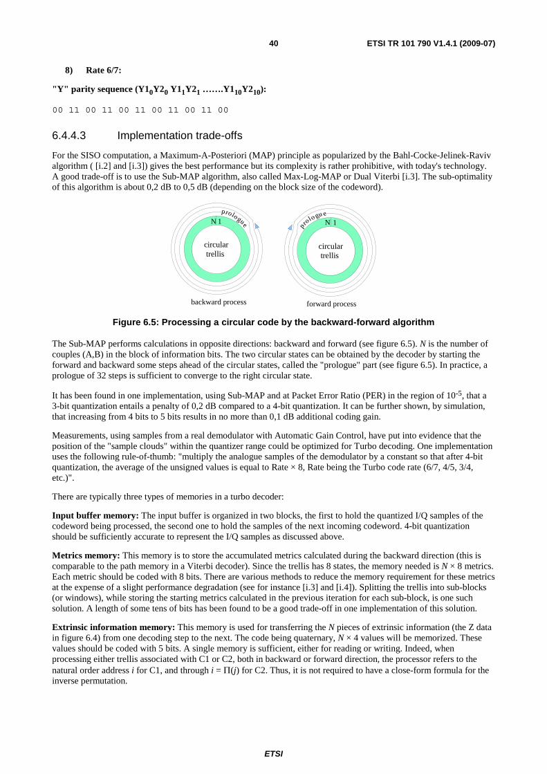
ETSI
ETSI TR 101 790 V1.4.1 (2009-07) 40
8) Rate 6/7:
"Y" parity sequence (Y10Y20 Y11Y21 …….Y110Y210):
00 11 00 11 00 11 00 11 00 11 00
6.4.4.3 Implementation trade-offs
For the SISO computation, a Maximum-A-Posteriori (MAP) principle as popularized by the Bahl-Cocke-Jelinek-Raviv algorithm ( [i.2] and [i.3]) gives the best performance but its complexity is rather prohibitive, with today's technology. A good trade-off is to use the Sub-MAP algorithm, also called Max-Log-MAP or Dual Viterbi [i.3]. The sub-optimality of this algorithm is about 0,2 dB to 0,5 dB (depending on the block size of the codeword).
circular trellis
1N
pro lg
euo
backward process
circular trellis
1N
forward processpr
ol g euo
Figure 6.5: Processing a circular code by the backward-forward algorithm
The Sub-MAP performs calculations in opposite directions: backward and forward (see figure 6.5). N is the number of couples (A,B) in the block of information bits. The two circular states can be obtained by the decoder by starting the forward and backward some steps ahead of the circular states, called the "prologue" part (see figure 6.5). In practice, a prologue of 32 steps is sufficient to converge to the right circular state.
It has been found in one implementation, using Sub-MAP and at Packet Error Ratio (PER) in the region of 10-5, that a 3-bit quantization entails a penalty of 0,2 dB compared to a 4-bit quantization. It can be further shown, by simulation, that increasing from 4 bits to 5 bits results in no more than 0,1 dB additional coding gain.
Measurements, using samples from a real demodulator with Automatic Gain Control, have put into evidence that the position of the "sample clouds" within the quantizer range could be optimized for Turbo decoding. One implementation uses the following rule-of-thumb: "multiply the analogue samples of the demodulator by a constant so that after 4-bit quantization, the average of the unsigned values is equal to Rate × 8, Rate being the Turbo code rate (6/7, 4/5, 3/4, etc.)".
There are typically three types of memories in a turbo decoder:
Input buffer memory: The input buffer is organized in two blocks, the first to hold the quantized I/Q samples of the codeword being processed, the second one to hold the samples of the next incoming codeword. 4-bit quantization should be sufficiently accurate to represent the I/Q samples as discussed above.
Metrics memory: This memory is to store the accumulated metrics calculated during the backward direction (this is comparable to the path memory in a Viterbi decoder). Since the trellis has 8 states, the memory needed is N × 8 metrics. Each metric should be coded with 8 bits. There are various methods to reduce the memory requirement for these metrics at the expense of a slight performance degradation (see for instance [i.3] and [i.4]). Splitting the trellis into sub-blocks (or windows), while storing the starting metrics calculated in the previous iteration for each sub-block, is one such solution. A length of some tens of bits has been found to be a good trade-off in one implementation of this solution.
Extrinsic information memory: This memory is used for transferring the N pieces of extrinsic information (the Z data in figure 6.4) from one decoding step to the next. The code being quaternary, N × 4 values will be memorized. These values should be coded with 5 bits. A single memory is sufficient, either for reading or writing. Indeed, when processing either trellis associated with C1 or C2, both in backward or forward direction, the processor refers to the natural order address i for C1, and through i = Π(j) for C2. Thus, it is not required to have a close-form formula for the inverse permutation.
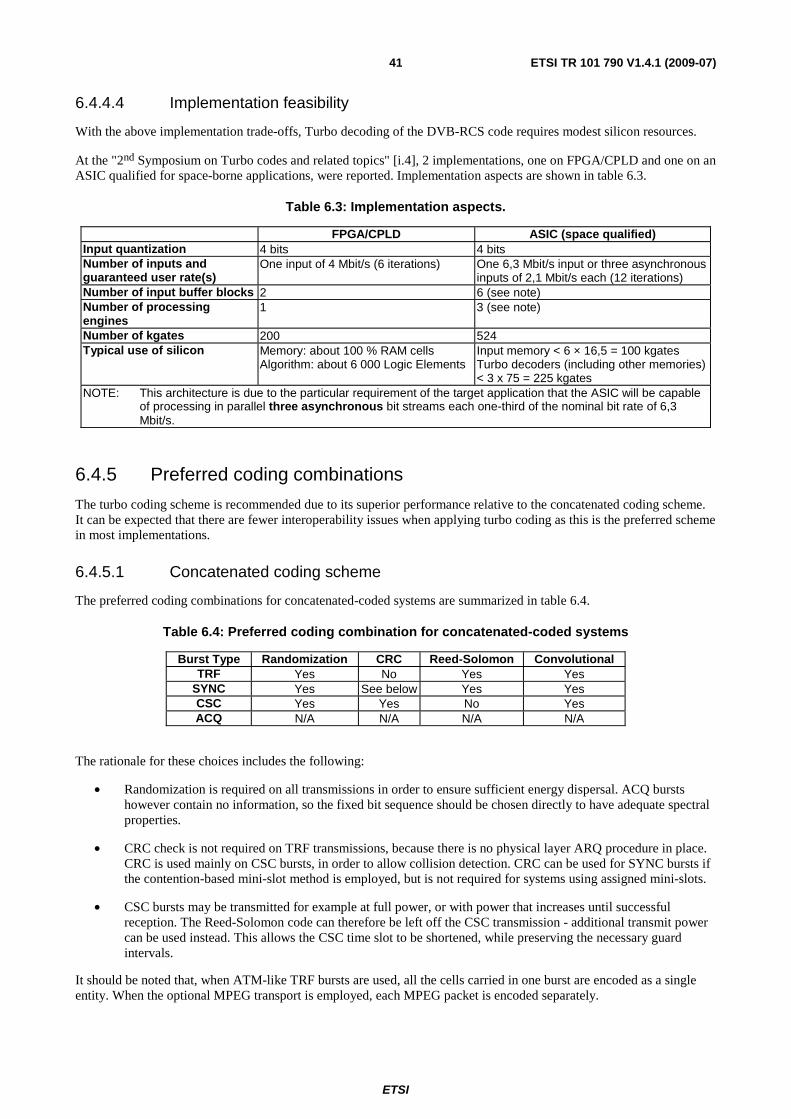
ETSI
ETSI TR 101 790 V1.4.1 (2009-07) 41
6.4.4.4 Implementation feasibility
With the above implementation trade-offs, Turbo decoding of the DVB-RCS code requires modest silicon resources.
At the "2nd Symposium on Turbo codes and related topics" [i.4], 2 implementations, one on FPGA/CPLD and one on an ASIC qualified for space-borne applications, were reported. Implementation aspects are shown in table 6.3.
Table 6.3: Implementation aspects.
FPGA/CPLD ASIC (space qualified) Input quantization 4 bits 4 bits Number of inputs and guaranteed user rate(s)
One input of 4 Mbit/s (6 iterations) One 6,3 Mbit/s input or three asynchronous inputs of 2,1 Mbit/s each (12 iterations)
Number of input buffer blocks 2 6 (see note) Number of processing engines
1 3 (see note)
Number of kgates 200 524 Typical use of silicon Memory: about 100 % RAM cells
Algorithm: about 6 000 Logic Elements Input memory < 6 × 16,5 = 100 kgates Turbo decoders (including other memories) < 3 x 75 = 225 kgates
NOTE: This architecture is due to the particular requirement of the target application that the ASIC will be capable of processing in parallel three asynchronous bit streams each one-third of the nominal bit rate of 6,3 Mbit/s.
6.4.5 Preferred coding combinations
The turbo coding scheme is recommended due to its superior performance relative to the concatenated coding scheme. It can be expected that there are fewer interoperability issues when applying turbo coding as this is the preferred scheme in most implementations.
6.4.5.1 Concatenated coding scheme
The preferred coding combinations for concatenated-coded systems are summarized in table 6.4.
Table 6.4: Preferred coding combination for concatenated-coded systems
Burst Type Randomization CRC Reed-Solomon Convolutional TRF Yes No Yes Yes
SYNC Yes See below Yes Yes CSC Yes Yes No Yes ACQ N/A N/A N/A N/A
The rationale for these choices includes the following:
• Randomization is required on all transmissions in order to ensure sufficient energy dispersal. ACQ bursts however contain no information, so the fixed bit sequence should be chosen directly to have adequate spectral properties.
• CRC check is not required on TRF transmissions, because there is no physical layer ARQ procedure in place. CRC is used mainly on CSC bursts, in order to allow collision detection. CRC can be used for SYNC bursts if the contention-based mini-slot method is employed, but is not required for systems using assigned mini-slots.
• CSC bursts may be transmitted for example at full power, or with power that increases until successful reception. The Reed-Solomon code can therefore be left off the CSC transmission - additional transmit power can be used instead. This allows the CSC time slot to be shortened, while preserving the necessary guard intervals.
It should be noted that, when ATM-like TRF bursts are used, all the cells carried in one burst are encoded as a single entity. When the optional MPEG transport is employed, each MPEG packet is encoded separately.
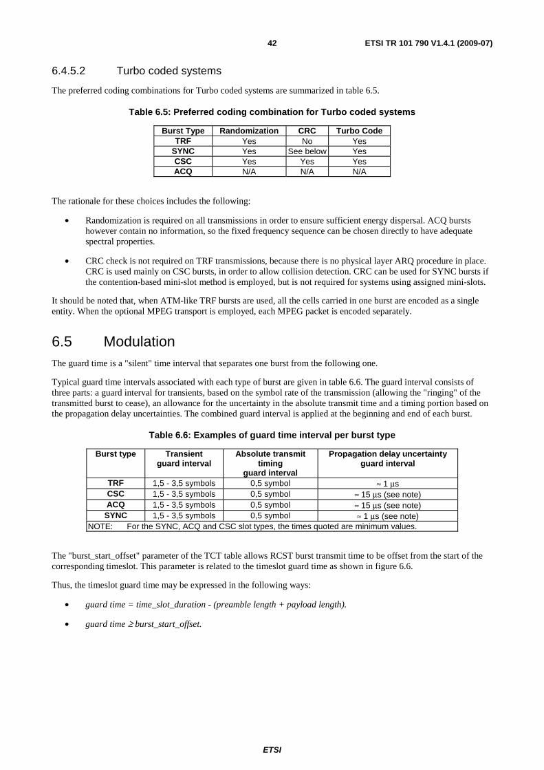
ETSI
ETSI TR 101 790 V1.4.1 (2009-07) 42
6.4.5.2 Turbo coded systems
The preferred coding combinations for Turbo coded systems are summarized in table 6.5.
Table 6.5: Preferred coding combination for Turbo coded systems
Burst Type Randomization CRC Turbo Code TRF Yes No Yes
SYNC Yes See below Yes CSC Yes Yes Yes ACQ N/A N/A N/A
The rationale for these choices includes the following:
• Randomization is required on all transmissions in order to ensure sufficient energy dispersal. ACQ bursts however contain no information, so the fixed frequency sequence can be chosen directly to have adequate spectral properties.
• CRC check is not required on TRF transmissions, because there is no physical layer ARQ procedure in place. CRC is used mainly on CSC bursts, in order to allow collision detection. CRC can be used for SYNC bursts if the contention-based mini-slot method is employed, but is not required for systems using assigned mini-slots.
It should be noted that, when ATM-like TRF bursts are used, all the cells carried in one burst are encoded as a single entity. When the optional MPEG transport is employed, each MPEG packet is encoded separately.
6.5 Modulation The guard time is a "silent" time interval that separates one burst from the following one.
Typical guard time intervals associated with each type of burst are given in table 6.6. The guard interval consists of three parts: a guard interval for transients, based on the symbol rate of the transmission (allowing the "ringing" of the transmitted burst to cease), an allowance for the uncertainty in the absolute transmit time and a timing portion based on the propagation delay uncertainties. The combined guard interval is applied at the beginning and end of each burst.
Table 6.6: Examples of guard time interval per burst type
Burst type Transient guard interval
Absolute transmit timing
guard interval
Propagation delay uncertainty guard interval
TRF 1,5 - 3,5 symbols 0,5 symbol ≈ 1 μs CSC 1,5 - 3,5 symbols 0,5 symbol ≈ 15 μs (see note) ACQ 1,5 - 3,5 symbols 0,5 symbol ≈ 15 μs (see note)
SYNC 1,5 - 3,5 symbols 0,5 symbol ≈ 1 μs (see note) NOTE: For the SYNC, ACQ and CSC slot types, the times quoted are minimum values.
The "burst_start_offset" parameter of the TCT table allows RCST burst transmit time to be offset from the start of the corresponding timeslot. This parameter is related to the timeslot guard time as shown in figure 6.6.
Thus, the timeslot guard time may be expressed in the following ways:
• guard time = time_slot_duration - (preamble length + payload length).
• guard time ≥ burst_start_offset.
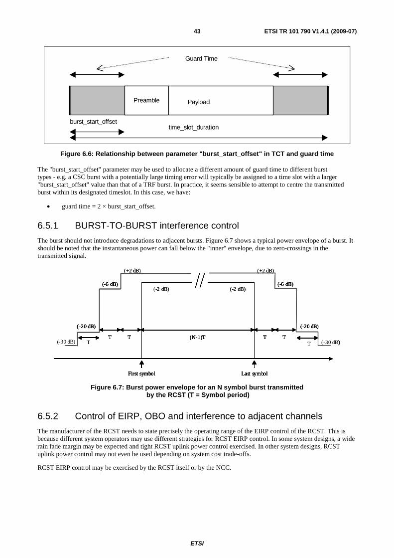
ETSI
ETSI TR 101 790 V1.4.1 (2009-07) 43
burst_start_offsettime_slot_duration
PayloadPreamble
Guard Time
Figure 6.6: Relationship between parameter "burst_start_offset" in TCT and guard time
The "burst_start_offset" parameter may be used to allocate a different amount of guard time to different burst types - e.g. a CSC burst with a potentially large timing error will typically be assigned to a time slot with a larger "burst_start_offset" value than that of a TRF burst. In practice, it seems sensible to attempt to centre the transmitted burst within its designated timeslot. In this case, we have:
• guard time = 2 × burst_start_offset.
6.5.1 BURST-TO-BURST interference control
The burst should not introduce degradations to adjacent bursts. Figure 6.7 shows a typical power envelope of a burst. It should be noted that the instantaneous power can fall below the "inner" envelope, due to zero-crossings in the transmitted signal.
(-6 dB)
T TT
(N-1)T
(-20 dB)
T T(-30 dB)T(-30 dB)
(-6 dB)
(-20 dB)
First symbol Last symbol
(-2 dB)
(+2 dB)
(-6 dB)
T TT
(N-1)T
(-2 dB)
(+2 dB)
(-20 dB)
T T(-30 dB)T(-30 dB)
(-6 dB)
(-20 dB)
First symbol Last symbol
(-6 dB)
T TT
(N-1)T
(-20 dB)
T T(-30 dB)T(-30 dB)
(-6 dB)
(-20 dB)
First symbol Last symbol
(-2 dB)
(+2 dB)
(-6 dB)
T TT
(N-1)T
(-2 dB)
(+2 dB)
(-20 dB)
T T(-30 dB)T(-30 dB)
(-6 dB)
(-20 dB)
First symbol Last symbol
Figure 6.7: Burst power envelope for an N symbol burst transmitted by the RCST (T = Symbol period)
6.5.2 Control of EIRP, OBO and interference to adjacent channels
The manufacturer of the RCST needs to state precisely the operating range of the EIRP control of the RCST. This is because different system operators may use different strategies for RCST EIRP control. In some system designs, a wide rain fade margin may be expected and tight RCST uplink power control exercised. In other system designs, RCST uplink power control may not even be used depending on system cost trade-offs.
RCST EIRP control may be exercised by the RCST itself or by the NCC.
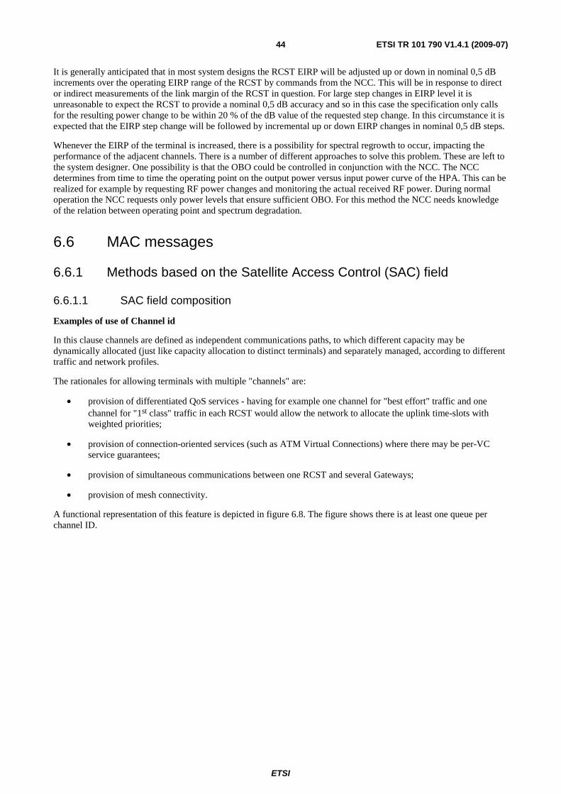
ETSI
ETSI TR 101 790 V1.4.1 (2009-07) 44
It is generally anticipated that in most system designs the RCST EIRP will be adjusted up or down in nominal 0,5 dB increments over the operating EIRP range of the RCST by commands from the NCC. This will be in response to direct or indirect measurements of the link margin of the RCST in question. For large step changes in EIRP level it is unreasonable to expect the RCST to provide a nominal 0,5 dB accuracy and so in this case the specification only calls for the resulting power change to be within 20 % of the dB value of the requested step change. In this circumstance it is expected that the EIRP step change will be followed by incremental up or down EIRP changes in nominal 0,5 dB steps.
Whenever the EIRP of the terminal is increased, there is a possibility for spectral regrowth to occur, impacting the performance of the adjacent channels. There is a number of different approaches to solve this problem. These are left to the system designer. One possibility is that the OBO could be controlled in conjunction with the NCC. The NCC determines from time to time the operating point on the output power versus input power curve of the HPA. This can be realized for example by requesting RF power changes and monitoring the actual received RF power. During normal operation the NCC requests only power levels that ensure sufficient OBO. For this method the NCC needs knowledge of the relation between operating point and spectrum degradation.
6.6 MAC messages
6.6.1 Methods based on the Satellite Access Control (SAC) field
6.6.1.1 SAC field composition
Examples of use of Channel id
In this clause channels are defined as independent communications paths, to which different capacity may be dynamically allocated (just like capacity allocation to distinct terminals) and separately managed, according to different traffic and network profiles.
The rationales for allowing terminals with multiple "channels" are:
• provision of differentiated QoS services - having for example one channel for "best effort" traffic and one channel for "1st class" traffic in each RCST would allow the network to allocate the uplink time-slots with weighted priorities;
• provision of connection-oriented services (such as ATM Virtual Connections) where there may be per-VC service guarantees;
• provision of simultaneous communications between one RCST and several Gateways;
• provision of mesh connectivity.
A functional representation of this feature is depicted in figure 6.8. The figure shows there is at least one queue per channel ID.

ETSI
ETSI TR 101 790 V1.4.1 (2009-07) 45
Channel_id 0
Channel_id 1
Channel_id 2
From
End
Use
r
User i/f Air i/f
Capacity Requests(per channel_id)
RCST
To
Sate
llit
e
"Channelizer"
Figure 6.8: Functional representation of Channel_id Usage
In all cases, it is understood that the number and usage of different channels per terminal is left to the network operator decision.
Examples of use of the "Routing_Label" identifier
The values of the "Routing_Label" identifier sub-field is given by the NCCs, as for the "Channel_id" values, at call establishment. The bit fields description inside these 2 bytes does not have to be defined any further.
For clarity reasons, an example of possible definition of the "Routing_Label" identifier sub-fields is given for a system with the following switching/routing requirements.
Table 6.7: Regenerative OBP switching architecture: Example of allocation of bits in the routing label used in case of OBP label routing/switching
Feature Number Allocated bits Number of downlink TDM streams 128 7 Quality of services levels 3 2 Number of Interactive Networks 16 4 Multicast address flag Y/N 1 TOTAL 12 288 14 bits
6.6.2 Data Unit Labelling Method (DULM)
It is adviced against reliance on DULM in systems that are not designed to apply DULM according to a supplemental specification, due to the risk of lack of support in implementations and the risk of incompatibility.
As stated in [i.2], the DULM with ATM transport does not use the method described in [i.5], but uses AAL5 encapsulation as specified in ITU-T Recommendation I.363-5 [i.36].
An example of a connection control protocol which uses the DULM mechanism is described in annex J.
6.7 Multiple access There may be advantages in organizing the superframe according to the following conditions (see also clause 8.2):
• Frames should have the same duration.
• A frame on a given frequency should carry homogeneous traffic; that is, the bit rate, the code rate and the burst length should be constant.
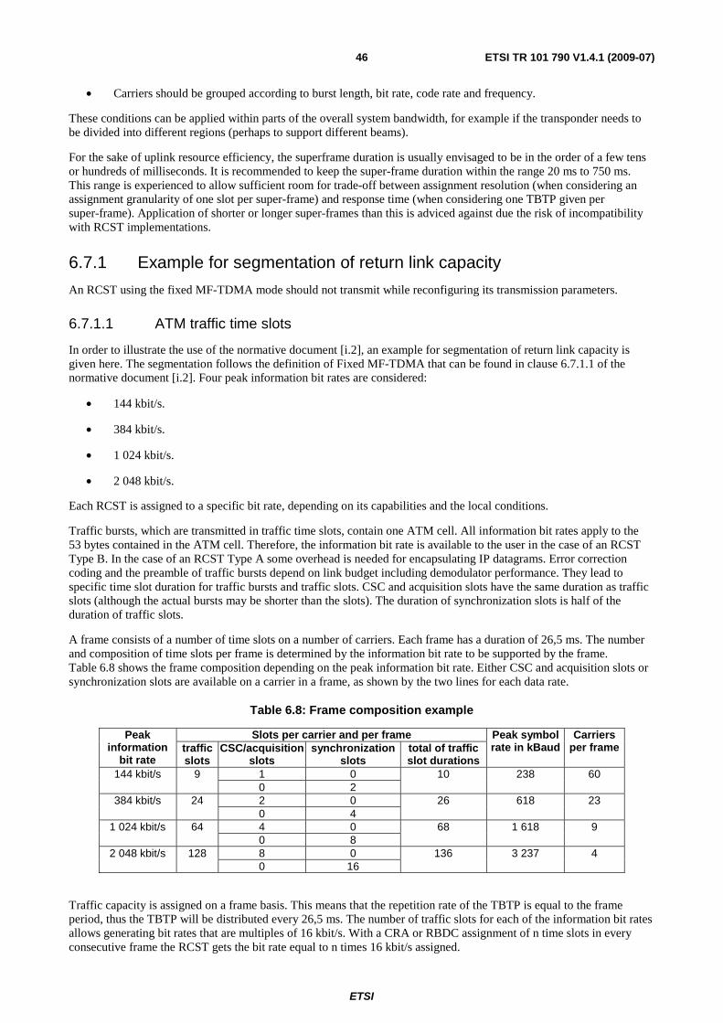
ETSI
ETSI TR 101 790 V1.4.1 (2009-07) 46
• Carriers should be grouped according to burst length, bit rate, code rate and frequency.
These conditions can be applied within parts of the overall system bandwidth, for example if the transponder needs to be divided into different regions (perhaps to support different beams).
For the sake of uplink resource efficiency, the superframe duration is usually envisaged to be in the order of a few tens or hundreds of milliseconds. It is recommended to keep the super-frame duration within the range 20 ms to 750 ms. This range is experienced to allow sufficient room for trade-off between assignment resolution (when considering an assignment granularity of one slot per super-frame) and response time (when considering one TBTP given per super-frame). Application of shorter or longer super-frames than this is adviced against due the risk of incompatibility with RCST implementations.
6.7.1 Example for segmentation of return link capacity
An RCST using the fixed MF-TDMA mode should not transmit while reconfiguring its transmission parameters.
6.7.1.1 ATM traffic time slots
In order to illustrate the use of the normative document [i.2], an example for segmentation of return link capacity is given here. The segmentation follows the definition of Fixed MF-TDMA that can be found in clause 6.7.1.1 of the normative document [i.2]. Four peak information bit rates are considered:
• 144 kbit/s.
• 384 kbit/s.
• 1 024 kbit/s.
• 2 048 kbit/s.
Each RCST is assigned to a specific bit rate, depending on its capabilities and the local conditions.
Traffic bursts, which are transmitted in traffic time slots, contain one ATM cell. All information bit rates apply to the 53 bytes contained in the ATM cell. Therefore, the information bit rate is available to the user in the case of an RCST Type B. In the case of an RCST Type A some overhead is needed for encapsulating IP datagrams. Error correction coding and the preamble of traffic bursts depend on link budget including demodulator performance. They lead to specific time slot duration for traffic bursts and traffic slots. CSC and acquisition slots have the same duration as traffic slots (although the actual bursts may be shorter than the slots). The duration of synchronization slots is half of the duration of traffic slots.
A frame consists of a number of time slots on a number of carriers. Each frame has a duration of 26,5 ms. The number and composition of time slots per frame is determined by the information bit rate to be supported by the frame. Table 6.8 shows the frame composition depending on the peak information bit rate. Either CSC and acquisition slots or synchronization slots are available on a carrier in a frame, as shown by the two lines for each data rate.
Table 6.8: Frame composition example
Slots per carrier and per frame Peak information
bit rate traffic slots
CSC/acquisition slots
synchronization slots
total of traffic slot durations
Peak symbol rate in kBaud
Carriers per frame
1 0 144 kbit/s 9 0 2
10 238 60
2 0 384 kbit/s 24 0 4
26 618 23
4 0 1 024 kbit/s 64 0 8
68 1 618 9
8 0 2 048 kbit/s 128 0 16
136 3 237 4
Traffic capacity is assigned on a frame basis. This means that the repetition rate of the TBTP is equal to the frame period, thus the TBTP will be distributed every 26,5 ms. The number of traffic slots for each of the information bit rates allows generating bit rates that are multiples of 16 kbit/s. With a CRA or RBDC assignment of n time slots in every consecutive frame the RCST gets the bit rate equal to n times 16 kbit/s assigned.
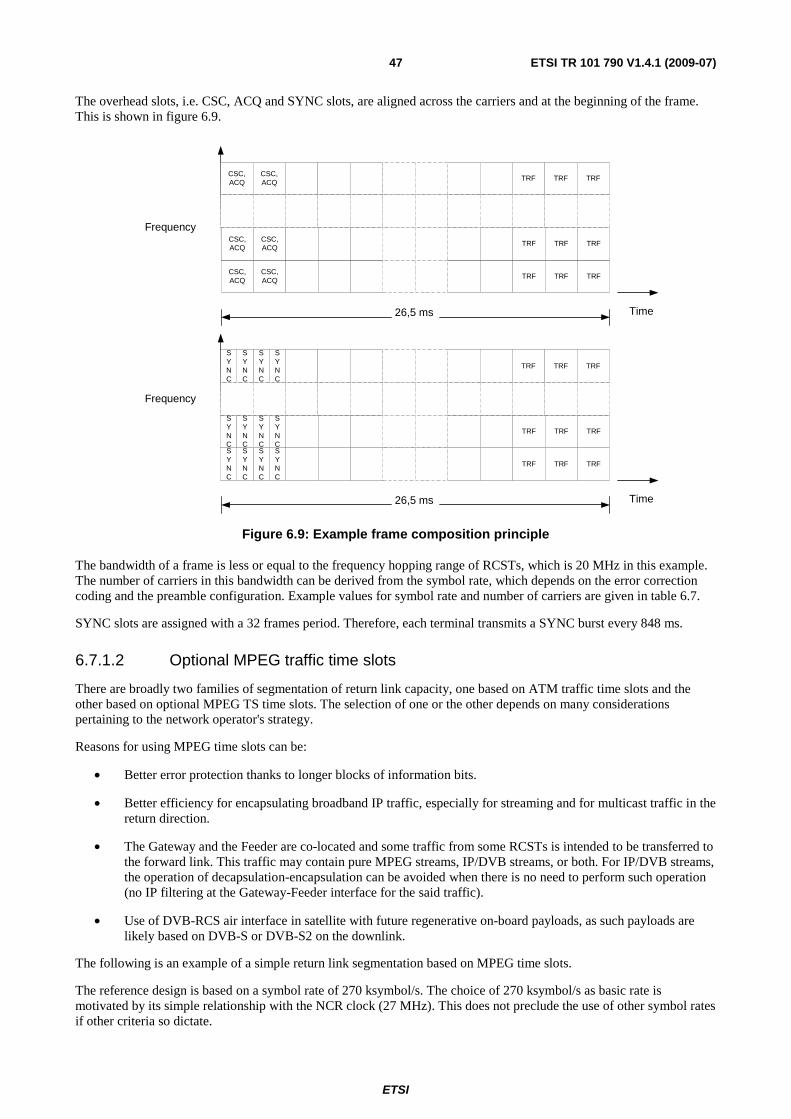
ETSI
ETSI TR 101 790 V1.4.1 (2009-07) 47
The overhead slots, i.e. CSC, ACQ and SYNC slots, are aligned across the carriers and at the beginning of the frame. This is shown in figure 6.9.
Frequency
Time26,5 ms
CSC,ACQ
CSC,ACQ
TRF TRF TRF
CSC,ACQ
CSC,ACQ
TRF TRF TRF
CSC,ACQ
CSC,ACQ
TRF TRF TRF
Time
Frequency
26,5 ms
TRF TRF TRF
TRF TRF TRF
TRF TRF TRF
SYNC
SYNC
SYNC
SYNC
SYNC
SYNC
SYNC
SYNC
SYNC
SYNC
SYNC
SYNC
Figure 6.9: Example frame composition principle
The bandwidth of a frame is less or equal to the frequency hopping range of RCSTs, which is 20 MHz in this example. The number of carriers in this bandwidth can be derived from the symbol rate, which depends on the error correction coding and the preamble configuration. Example values for symbol rate and number of carriers are given in table 6.7.
SYNC slots are assigned with a 32 frames period. Therefore, each terminal transmits a SYNC burst every 848 ms.
6.7.1.2 Optional MPEG traffic time slots
There are broadly two families of segmentation of return link capacity, one based on ATM traffic time slots and the other based on optional MPEG TS time slots. The selection of one or the other depends on many considerations pertaining to the network operator's strategy.
Reasons for using MPEG time slots can be:
• Better error protection thanks to longer blocks of information bits.
• Better efficiency for encapsulating broadband IP traffic, especially for streaming and for multicast traffic in the return direction.
• The Gateway and the Feeder are co-located and some traffic from some RCSTs is intended to be transferred to the forward link. This traffic may contain pure MPEG streams, IP/DVB streams, or both. For IP/DVB streams, the operation of decapsulation-encapsulation can be avoided when there is no need to perform such operation (no IP filtering at the Gateway-Feeder interface for the said traffic).
• Use of DVB-RCS air interface in satellite with future regenerative on-board payloads, as such payloads are likely based on DVB-S or DVB-S2 on the downlink.
The following is an example of a simple return link segmentation based on MPEG time slots.
The reference design is based on a symbol rate of 270 ksymbol/s. The choice of 270 ksymbol/s as basic rate is motivated by its simple relationship with the NCR clock (27 MHz). This does not preclude the use of other symbol rates if other criteria so dictate.
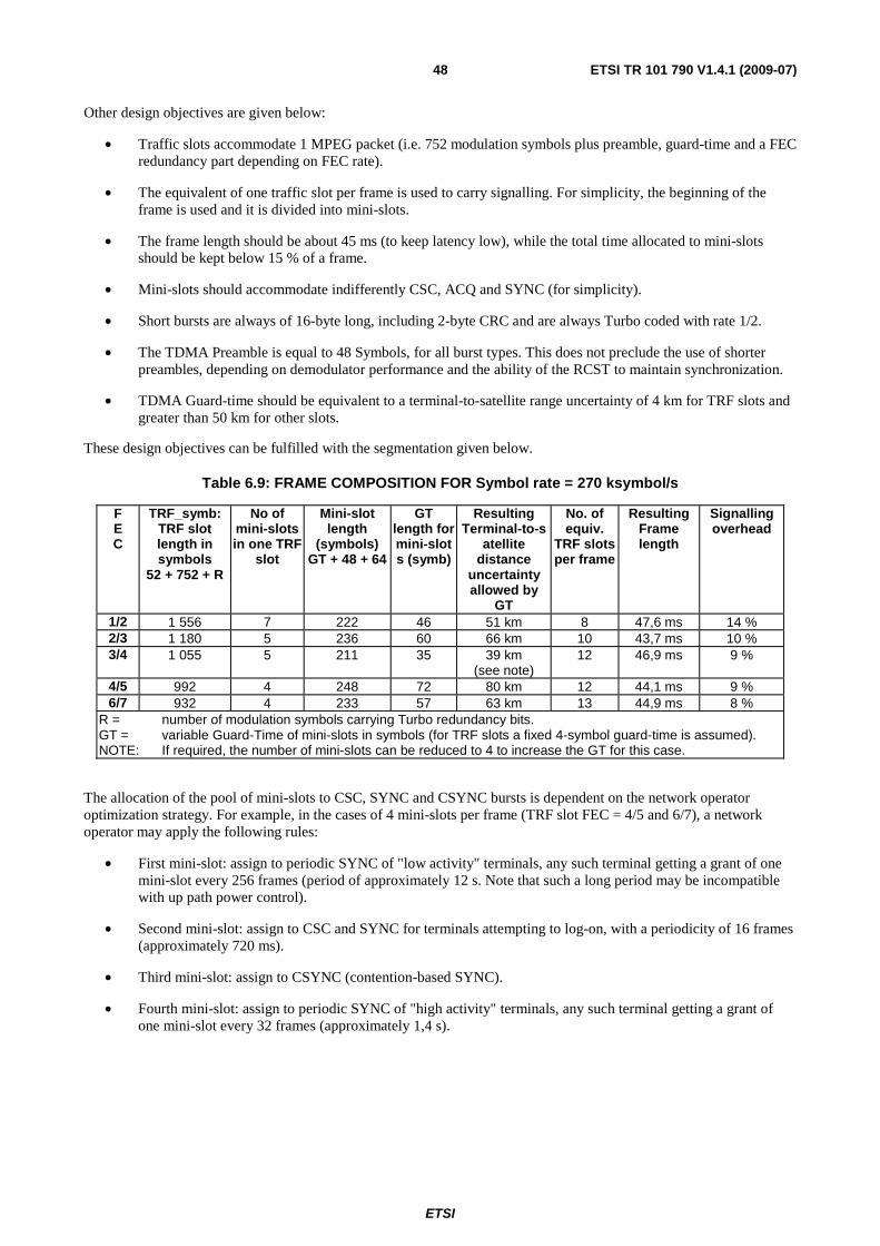
ETSI
ETSI TR 101 790 V1.4.1 (2009-07) 48
Other design objectives are given below:
• Traffic slots accommodate 1 MPEG packet (i.e. 752 modulation symbols plus preamble, guard-time and a FEC redundancy part depending on FEC rate).
• The equivalent of one traffic slot per frame is used to carry signalling. For simplicity, the beginning of the frame is used and it is divided into mini-slots.
• The frame length should be about 45 ms (to keep latency low), while the total time allocated to mini-slots should be kept below 15 % of a frame.
• Mini-slots should accommodate indifferently CSC, ACQ and SYNC (for simplicity).
• Short bursts are always of 16-byte long, including 2-byte CRC and are always Turbo coded with rate 1/2.
• The TDMA Preamble is equal to 48 Symbols, for all burst types. This does not preclude the use of shorter preambles, depending on demodulator performance and the ability of the RCST to maintain synchronization.
• TDMA Guard-time should be equivalent to a terminal-to-satellite range uncertainty of 4 km for TRF slots and greater than 50 km for other slots.
These design objectives can be fulfilled with the segmentation given below.
Table 6.9: FRAME COMPOSITION FOR Symbol rate = 270 ksymbol/s
F E C
TRF_symb: TRF slot length in symbols
52 + 752 + R
No of mini-slots in one TRF
slot
Mini-slot length
(symbols) GT + 48 + 64
GT length for mini-slots (symb)
Resulting Terminal-to-s
atellite distance
uncertainty allowed by
GT
No. of equiv.
TRF slots per frame
Resulting Frame length
Signalling overhead
1/2 1 556 7 222 46 51 km 8 47,6 ms 14 % 2/3 1 180 5 236 60 66 km 10 43,7 ms 10 % 3/4 1 055 5 211 35 39 km
(see note) 12 46,9 ms 9 %
4/5 992 4 248 72 80 km 12 44,1 ms 9 % 6/7 932 4 233 57 63 km 13 44,9 ms 8 %
R = number of modulation symbols carrying Turbo redundancy bits. GT = variable Guard-Time of mini-slots in symbols (for TRF slots a fixed 4-symbol guard-time is assumed). NOTE: If required, the number of mini-slots can be reduced to 4 to increase the GT for this case.
The allocation of the pool of mini-slots to CSC, SYNC and CSYNC bursts is dependent on the network operator optimization strategy. For example, in the cases of 4 mini-slots per frame (TRF slot FEC = 4/5 and 6/7), a network operator may apply the following rules:
• First mini-slot: assign to periodic SYNC of "low activity" terminals, any such terminal getting a grant of one mini-slot every 256 frames (period of approximately 12 s. Note that such a long period may be incompatible with up path power control).
• Second mini-slot: assign to CSC and SYNC for terminals attempting to log-on, with a periodicity of 16 frames (approximately 720 ms).
• Third mini-slot: assign to CSYNC (contention-based SYNC).
• Fourth mini-slot: assign to periodic SYNC of "high activity" terminals, any such terminal getting a grant of one mini-slot every 32 frames (approximately 1,4 s).
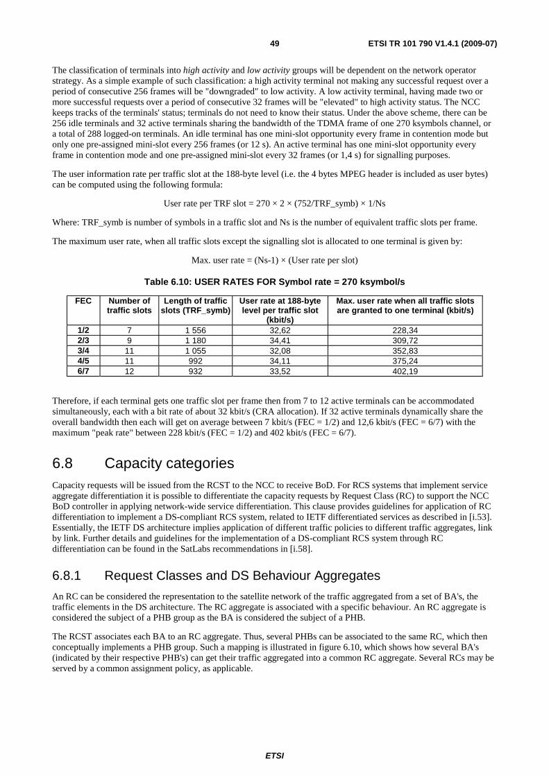
ETSI
ETSI TR 101 790 V1.4.1 (2009-07) 49
The classification of terminals into high activity and low activity groups will be dependent on the network operator strategy. As a simple example of such classification: a high activity terminal not making any successful request over a period of consecutive 256 frames will be "downgraded" to low activity. A low activity terminal, having made two or more successful requests over a period of consecutive 32 frames will be "elevated" to high activity status. The NCC keeps tracks of the terminals' status; terminals do not need to know their status. Under the above scheme, there can be 256 idle terminals and 32 active terminals sharing the bandwidth of the TDMA frame of one 270 ksymbols channel, or a total of 288 logged-on terminals. An idle terminal has one mini-slot opportunity every frame in contention mode but only one pre-assigned mini-slot every 256 frames (or 12 s). An active terminal has one mini-slot opportunity every frame in contention mode and one pre-assigned mini-slot every 32 frames (or 1,4 s) for signalling purposes.
The user information rate per traffic slot at the 188-byte level (i.e. the 4 bytes MPEG header is included as user bytes) can be computed using the following formula:
User rate per TRF slot = 270 × 2 × (752/TRF_symb) × 1/Ns
Where: TRF_symb is number of symbols in a traffic slot and Ns is the number of equivalent traffic slots per frame.
The maximum user rate, when all traffic slots except the signalling slot is allocated to one terminal is given by:
Max. user rate = (Ns-1) × (User rate per slot)
Table 6.10: USER RATES FOR Symbol rate = 270 ksymbol/s
FEC Number of traffic slots
Length of traffic slots (TRF_symb)
User rate at 188-byte level per traffic slot
(kbit/s)
Max. user rate when all traffic slots are granted to one terminal (kbit/s)
1/2 7 1 556 32,62 228,34 2/3 9 1 180 34,41 309,72 3/4 11 1 055 32,08 352,83 4/5 11 992 34,11 375,24 6/7 12 932 33,52 402,19
Therefore, if each terminal gets one traffic slot per frame then from 7 to 12 active terminals can be accommodated simultaneously, each with a bit rate of about 32 kbit/s (CRA allocation). If 32 active terminals dynamically share the overall bandwidth then each will get on average between 7 kbit/s (FEC = 1/2) and 12,6 kbit/s (FEC = 6/7) with the maximum "peak rate" between 228 kbit/s (FEC = 1/2) and 402 kbit/s (FEC = 6/7).
6.8 Capacity categories Capacity requests will be issued from the RCST to the NCC to receive BoD. For RCS systems that implement service aggregate differentiation it is possible to differentiate the capacity requests by Request Class (RC) to support the NCC BoD controller in applying network-wide service differentiation. This clause provides guidelines for application of RC differentiation to implement a DS-compliant RCS system, related to IETF differentiated services as described in [i.53]. Essentially, the IETF DS architecture implies application of different traffic policies to different traffic aggregates, link by link. Further details and guidelines for the implementation of a DS-compliant RCS system through RC differentiation can be found in the SatLabs recommendations in [i.58].
6.8.1 Request Classes and DS Behaviour Aggregates
An RC can be considered the representation to the satellite network of the traffic aggregated from a set of BA's, the traffic elements in the DS architecture. The RC aggregate is associated with a specific behaviour. An RC aggregate is considered the subject of a PHB group as the BA is considered the subject of a PHB.
The RCST associates each BA to an RC aggregate. Thus, several PHBs can be associated to the same RC, which then conceptually implements a PHB group. Such a mapping is illustrated in figure 6.10, which shows how several BA's (indicated by their respective PHB's) can get their traffic aggregated into a common RC aggregate. Several RCs may be served by a common assignment policy, as applicable.
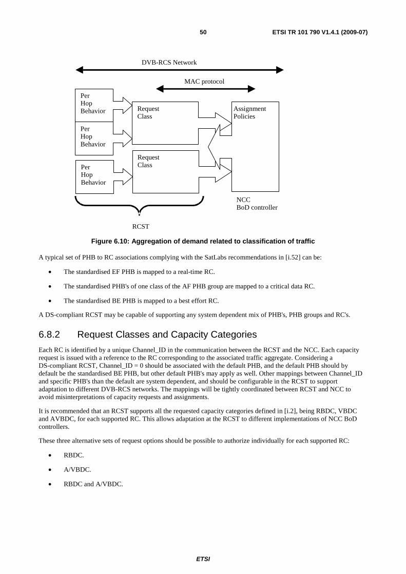
ETSI
ETSI TR 101 790 V1.4.1 (2009-07) 50
Request Class
Per Hop Behavior Request
Class Assignment Policies
DVB-RCS Network
MAC protocol
RCST
NCC BoD controller
Per Hop Behavior
Per Hop Behavior
Figure 6.10: Aggregation of demand related to classification of traffic
A typical set of PHB to RC associations complying with the SatLabs recommendations in [i.52] can be:
• The standardised EF PHB is mapped to a real-time RC.
• The standardised PHB's of one class of the AF PHB group are mapped to a critical data RC.
• The standardised BE PHB is mapped to a best effort RC.
A DS-compliant RCST may be capable of supporting any system dependent mix of PHB's, PHB groups and RC's.
6.8.2 Request Classes and Capacity Categories
Each RC is identified by a unique Channel_ID in the communication between the RCST and the NCC. Each capacity request is issued with a reference to the RC corresponding to the associated traffic aggregate. Considering a DS-compliant RCST, Channel_ID = 0 should be associated with the default PHB, and the default PHB should by default be the standardised BE PHB, but other default PHB's may apply as well. Other mappings between Channel_ID and specific PHB's than the default are system dependent, and should be configurable in the RCST to support adaptation to different DVB-RCS networks. The mappings will be tightly coordinated between RCST and NCC to avoid misinterpretations of capacity requests and assignments.
It is recommended that an RCST supports all the requested capacity categories defined in [i.2], being RBDC, VBDC and AVBDC, for each supported RC. This allows adaptation at the RCST to different implementations of NCC BoD controllers.
These three alternative sets of request options should be possible to authorize individually for each supported RC:
• RBDC.
• A/VBDC.
• RBDC and A/VBDC.
ETSI
ETSI TR 101 790 V1.4.1 (2009-07) 51
CRA and FCA should be possible to combine with any of the above. The applied level of CRA may be indicated per RC in order to support RC based differentiation with CRA. CRA can e.g. be associated to the RC that has the most demanding requirements to the assignment characteristics, so that any excess assignment can be utilized by any other RC without failing to comply with the corresponding service specifications.
If the NCC authorizes A/VBDC, the RCST may assume that support for both AVBDC and VBDC is offered for the associated RC. The combination of AVBDC and VBDC should be considered as a single capacity category, here denoted A/VBDC, as these are tightly related through the specifications in [i.2].
The authorization of which request options that may be used for each RC should be tightly coordinated with the NCC. The RCST should refrain from using a requested capacity category for an RC if this is not explicitly authorized by the NCC. When the NCC authorizes the request option with most flexibibility (both RBDC and A/VBDC) for an RC, the RCST will have to request with at least one of those signals. When the NCC authorizes one of the limited request options (RBDC or A/VBDC) for an RC, the RCST will have to request with a signal from the specific option.
6.8.3 Request Classes and Admission Control
It may be desirable to support admission control per RCST and service to improve the user experience, and utilize resources more efficiently. RC's may be utilised to implement such admission control. This may be supported by supplemental specifications to coordinate the NCC and RCST implementations.
6.8.4 Guidelines for the Capacity Categories
Similar guidelines as found in this clause as well as supplemental guidelines can be found in the SatLabs system recommendations in [i.58].
6.8.4.1 Continuous Rate Assignment
Continuous Rate Assignment (CRA) is recommended implemented as follows:
• It is allocated as a static rate, hence it is not subject to the dynamic requests as defined in [i.2].
• It is allocated in full every superframe, whether the RCST has traffic to transmit or not.
• The indicated rate is in given in burst payload bit/s (considering ATM and MPEG as payload), see [i.2].
• The allocated CRA level is indicated to an RCST at the latest at the time of logon.
• No overbooking is made. The indicated CRA level is provided for the whole duration of the commitment (i.e. the logon session).
• Allocated CRA level is indicated per RC.
6.8.4.2 Rate-Based Dynamic Capacity
Rate Based Dynamic Capacity (RBDC) is recommended implemented as follows:
• Requests are made in units of 2 or 32 kbit/s depending on the applied scaling factor as defined in [i.2]. It is similar to CRA, but dynamic in nature (based on requests).
• The requested rate is given in burst payload bit/s (considering ATM and MPEG as payload), see [i.2].
• An RBDC request is absolute and invalidates previous RBDC requests for the same RC.
Recommended RBDC control parameters and the related behaviour per RC are as follows:
• Assignment is guaranteed (up to RBDCmax) if the service is not overbooked. When overbooked, a fair sharing may be applied.
ETSI
ETSI TR 101 790 V1.4.1 (2009-07) 52
• RBDCmax is the maximum RBDC rate the RCST is authorized to request, and may also be the maximum that the NCC is prepared to assign. It is expressed in units of 2 kbit/s according to [i.2].
• RBDCtimeOut is the time for which an RBDC request is valid, i.e. it is the persistence of an RBDC request received at the NCC. It is expressed in superframes. The range for the RBDC timeout should be larger than the [1,15] superframes specified in [i.2], and any applied default should be related to a reasonable time interval, not a number of superframes as this may result in very different default RBDC timeouts in different systems.
• RBDCmax and RBDCtimeOut should be configurable per RC.
• RBDCmax=0 indicates that use of RBDC is not authorized for the respective RC.
6.8.4.3 Volume-Based Dynamic Capacity
Volume Based Dynamic Capacity (VBDC) is recommended implemented as follows:
• VBDC requests are made in units of a single-payload-unit (one ATM cell or one MPEG PES packet) or units of 16-payload-units units depending on the scaling factor, as defined in [i.2].
• VBDC requests are cumulative per RC ("Cumulative" means that the RCST issues a VBDC request and expects this to be accrued to the previous AVBDC request or previously accrued A/VBDC requests at the NCC.).
Recommended VBDC control parameters and the related behaviour per RC are as follows:
• VBDCmax: Maximum number of payload units per superframe allocated to the RC through A/VBDC. This is not necessarily implemented as an absolute value for each superframe, i.e. it can be an average over several superframes.
• VBDCmaxBacklog indicates the absolute ceiling of A/VBDC backlog of requested traffic at the NCC for the RC. It is expressed in bytes.
• VBDCtimeOut represents the VBDC backlog persistence idle time limit at the NCC for the RC. It is reset at the RCST when an A/VBDC request is sent. If the latest A/VBDC request has not been fully served when VBDCtimeOut expires, the RCST may consider that none of the pending requests will be served. The RCST may then issue a new request for the remaining traffic. This request should be an AVBDC request. VBDCtimeOut is expressed in superframes.
• VBDCmax, VBDCmaxBacklog and VBDCtimeOut should be configurable per RC and should be tightly coordinated with the NCC.
• VBDCmaxBacklog = 0 or VBDCmax = 0 indicates that use of A/VBDC is not authorized for the respective RC.
Any non-zero AVBDC and VBDC request issued for the respective RC is implicitly interpreted as a VBDCtimeOut timer reset for the respective RC.
The RCST may use VBDCmax and VBDCmaxBacklog in order to limit its A/VBDC requests. By respecting the limits the RCST may expect to avoid that the NCC drops AVBDC and VBDC capacity requests due to backlog overflow.
6.8.4.4 Absolute Volume Based Dynamic Capacity
Absolute VBDC (AVBDC) is recommended implemented as follows:
• AVBDC requests are absolute and, when received at NCC, invalidate previous A/VBDC requests issued by the RCST for the same RC, as defined in [i.2].
• AVBDC requested volume relates to the VBDC component of the buffer of the respective RC at the RCST.
RCST may send AVBDC request at any time. An AVBDC request may e.g. be sent when the NCC indicates that all A/VBDC request queues have been emptied (an optional TBTP flag, as specified in [i.2]).
ETSI
ETSI TR 101 790 V1.4.1 (2009-07) 53
6.9 Queuing and packet dispatching strategy The RCST will be capable of buffering traffic arriving from the user interface before submission to the satellite link. An RCST may support QoS differentiation in order to provide high quality for simultaneous heterogeneous services. One option is then to implement DS-compliant QoS differentiation according to the IETF archictecture for differentiated services described in [i.53]. Further details and guidelines can be found in the SatLabs recommendations in [i.52].
6.9.1 Guidelines for DS-compliant queueing and dispatching
The RCST will be capable of recognizing BA's by the applied DSCP value. A BA may also exclusively apply internally for a DVB-RCS network without any externally visible DSCP tagging of the associated IP packets, depending on the classification capabilites of the RCST, and by this the specific DVB-RCS system appears itself as a DS domain.
The RCST is assumed to aggregate BA traffic into RC aggregates as described for the capacity categories. Several BA's can be aggregated into each RC.
The queuing/dropping/dispatching for each BA will follow the service provisioning policies implemented, and these will be system dependent. An RCST may be claimed to support several of the PHB's standardised by the IETF and will then also comply with the corresponding service provisioning policy specifications, e.g. as provisioned for in the type of DS-compliant DVB-RCS implementation recommended by SatLabs in [i.52].
One or multiple RC aggregates may map to a data link (provisioned through VPI/VCI or PID as applicable). An RCST that supports both a real-time PHB as well as other types of PHB's should support use of at least two simultaneous data links (provisioned through multiple VPI/VCI's or multiple PID's as applicable) as offered by the NCC through the RIP descriptor. One of the data links should be readily available any time as required by the real-time BA and thus the RCST should support interleaving of transmission bursts containing traffic for the data links to limit the packet delay and delay jitter for the real-time BA.
An RCST should be capable of using any of the assigned slots to dispatch packets from any of the supported BA's to comply with the service provisioning policies as best as possible, independent of the RC associations indicated for the assigned slots.
Two system dependent options may apply. Packet dispatching by the RCST may be partly guided by indication of RC association per assigned slot, by use of the Channel_ID association of each slot. Packet dispatching by the RCST may also be strictly enforced per RC through that a slot only will be used for submission from the BA's associated to the RC indicated for the slot. None of these options should be applied by the RCST if not explicitly supported by supplemental specifications for the respective DVB-RCS system, as application solely at the RCST side may easily lead to reduced performance.
6.9.2 A two-stage traffic queueing DS architecture
An RCST QoS architecture, based on the DS framework, is illustrated in figure 6.11.
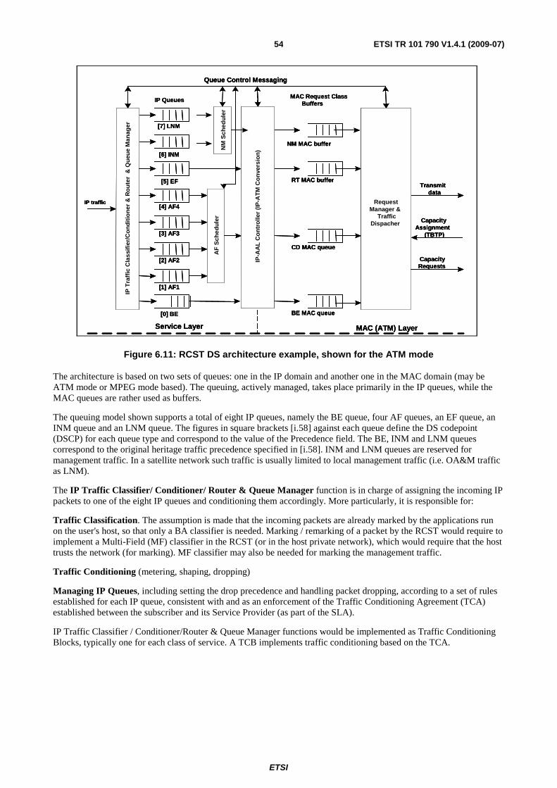
ETSI
ETSI TR 101 790 V1.4.1 (2009-07) 54
CapacityRequests
CapacityAssignment
(TBTP)
Transmitdata
AF
Sch
edu
ler
MAC (ATM) LayerService Layer
IP T
raff
ic C
lass
ifie
r/C
on
diti
on
er &
Ro
ute
r &
Qu
eue
Man
ager
IP Queues MAC Request ClassBuffers
RequestManager &
TrafficDispacher
IP traffic
IP-A
AL
Co
ntr
olle
r (I
P-A
TM
Co
nve
rsio
n)
Queue Control Messaging
NM MAC buffer
RT MAC buffer
CD MAC queue
BE MAC queue
[6] INM
[5] EF
[7] LNM
[1] AF1
[2] AF2
[3] AF3
[4] AF4
[0] BE
NM
Sch
edu
ler
CapacityRequests
CapacityAssignment
(TBTP)
Transmitdata
AF
Sch
edu
ler
MAC (ATM) LayerService Layer
IP T
raff
ic C
lass
ifie
r/C
on
diti
on
er &
Ro
ute
r &
Qu
eue
Man
ager
IP Queues MAC Request ClassBuffers
RequestManager &
TrafficDispacher
IP traffic
IP-A
AL
Co
ntr
olle
r (I
P-A
TM
Co
nve
rsio
n)
Queue Control Messaging
NM MAC buffer
RT MAC buffer
CD MAC queue
BE MAC queue
[6] INM
[5] EF
[7] LNM
[1] AF1
[2] AF2
[3] AF3
[4] AF4
[0] BE
NM
Sch
edu
ler
Figure 6.11: RCST DS architecture example, shown for the ATM mode
The architecture is based on two sets of queues: one in the IP domain and another one in the MAC domain (may be ATM mode or MPEG mode based). The queuing, actively managed, takes place primarily in the IP queues, while the MAC queues are rather used as buffers.
The queuing model shown supports a total of eight IP queues, namely the BE queue, four AF queues, an EF queue, an INM queue and an LNM queue. The figures in square brackets [i.58] against each queue define the DS codepoint (DSCP) for each queue type and correspond to the value of the Precedence field. The BE, INM and LNM queues correspond to the original heritage traffic precedence specified in [i.58]. INM and LNM queues are reserved for management traffic. In a satellite network such traffic is usually limited to local management traffic (i.e. OA&M traffic as LNM).
The IP Traffic Classifier/ Conditioner/ Router & Queue Manager function is in charge of assigning the incoming IP packets to one of the eight IP queues and conditioning them accordingly. More particularly, it is responsible for:
Traffic Classification. The assumption is made that the incoming packets are already marked by the applications run on the user's host, so that only a BA classifier is needed. Marking / remarking of a packet by the RCST would require to implement a Multi-Field (MF) classifier in the RCST (or in the host private network), which would require that the host trusts the network (for marking). MF classifier may also be needed for marking the management traffic.
Traffic Conditioning (metering, shaping, dropping)
Managing IP Queues, including setting the drop precedence and handling packet dropping, according to a set of rules established for each IP queue, consistent with and as an enforcement of the Traffic Conditioning Agreement (TCA) established between the subscriber and its Service Provider (as part of the SLA).
IP Traffic Classifier / Conditioner/Router & Queue Manager functions would be implemented as Traffic Conditioning Blocks, typically one for each class of service. A TCB implements traffic conditioning based on the TCA.
ETSI
ETSI TR 101 790 V1.4.1 (2009-07) 55
6.10 Guidelines for the requesting strategy Implementation specific request strategies apply. It is system dependent which capacity categories that apply fore each RC. RBDC might be useful e.g. for delay jitter sensitive traffic (like VoIP) and A/VBDC might be useful e.g. for more efficiency sensitive traffic (like best effort). An NCC BoD controller may allow both RBDC and A/VBDC to be applied for the same RC at the discretion of the RCST. The RBDC request level should indicate either all of the demand or the RBDC demand component for the associated RC aggregate. The A/VBDC request level should indicate either all of the demand or the A/VBDC demand component for the associated RC aggregate, with AVBDC being absolute A/VBDC demand and VBDC being an increment to previously indicated A/VBDC demand.
RBDC and AVBDC can in principle be sent anytime and repeated freely as these capacity categories are non-cumulative. The RCST may contribute to avoid unintended replication of assignments by limiting transmission of AVBDC to the situations where it can be assumed that there is no pending backlog of volume assignment. A similar risk exists when using RBDC and A/VBDC simultaneously for the same RC, and it is recommended that the RCST then explicitly avoids requesting for resources for the same volume of traffic both by RBDC and A/VBDC.
The RCST should subtract the RC specific known CRA from the demand for the RC aggregate before calculating capacity requests. The RCST should also, to the extent applicable, subtract remaining CRA from capacity requests across the supported RCs.
Considering DS-compliant implementations, requests for resources for the BA with the BE PHB should conform to certain offered-traffic-dependent maximum request levels like the strict bounds recommended by SatLabs in [i.52]. This allows the NCC BoD controller to distribute BE PHB resources among RCSTs with high precision. The request level for resources for other PHB types than BE is system dependent, but should be related to the offered traffic in the respective RC in a similar way as recommended for BE.
The policies for how to issue capacity requests within the available request opportunities are implementation dependent. An RCST may assume that the request opportunities provided by the NCC are sufficient to cope with BA and RC aggregate performance objectives, as applicable.
6.10.1 BoD queue synchronization method
This clause proposes a specific technique for using AVBDC capacity requests to maintain BoD queue synchronization between RCST and hub in the presence of transmission losses in forward and return MAC signalling.
An AVBDC request transmitted in an arbitrary superframe S, AVBDCS, can for example be calculated as:
AVBDCS = max(QS - AS, 0) + δ
where:
QS is the total VBDC queue at the start of superframe S.
AS is the VBDC + FCA component of any assignments signalled to the RCST in the TBTP for superframe S.
δ is an optional adjustment for some or all traffic received between the start of superframe S and the AVBDC transmission time.
The max( ) function ensures that the value QS - AS is never negative (i.e. is clipped at 0).
The NCC will maintain a matching AVBDC reference value adjusted to the arrival time of superframe S at the NCC, this reference value tracking AVBDC and VBDC requests received and VBDC + FCA assignments made, subject to that reference value never going negative. It will use the arriving AVBDC request to adjust the NCC VBDC cumulative count based on the difference from the reference, subject to that queue size never going negative. The reference value will be reset to the AVBDC request after this adjustment. This ensures that the RCST and NCC are both referenced to the same datum point.
It will be possible for an RCST to use AVBDC and VBDC in any combination as required, including exclusive use of AVBDC. For example, the self-correcting nature of the AVBDC makes it an interesting mechanism for contention mini-slots. It can also be used to re-calibrate the NCC VBDC cumulative count when the RCST senses that a VBDC request might be lost.
ETSI
ETSI TR 101 790 V1.4.1 (2009-07) 56
6.11 Assignment/allocation The NCC may relate a request for resources for a specific RC aggregate to an associated appropriate assignment/allocation policy, through the association with a specific Channel_ID. The NCC may also utilise the different capacity categories through differentiated authorization and application of capacity category specific policies.
Tagging of the slots in TBTP by the associated RC may be provided at the discretion of the NCC, by associating slots to the specific Channel_ID tagged to the corresponding request. The utilization of this information by the RCST is impelementation dependent.
6.12 Procedure for contention resolution When capacity requests (CR) are sent in contention slots (CS), there is a definite chance of a collision, which typically results in the capacity request being lost. In such situations, the RCST will want to reissue its capacity request. Mini-slot contention resolution by retransmission based on feedback is not recommended due to the significant delay this creates. Rather, it is recommended to limit the usage of contention based access, and to back up this signaling with an "open-loop" transmission replica in a non-contention channel if it is desired to limit the loss probability.
It is recommended that implementations only utilize contention based signaling as a performance oriented supplement to signaling in assigned slots. The support of contention based signaling can not be relied upon. It is recommended that implementations are designed to function both without such support as well as with insufficient contention resources.
7 Synchronization procedures
7.1 Overall events sequencing Terminals should know what the initial power level is that they can use when entering the network. The knowledge about this power level should be gathered during the installation procedure. Terminals will keep the information about this power level. In the typical RCST design, the IDU will use the corresponding IF level as the default transmitted IF power level for sending a CSC burst at RCST reboot or power on. During normal operation, the terminal should send CSCs with the same power level as used during installation, or adapt the power level.
The normative document [i.2] explicitly defines that the terminal should stay in HOLD state also after a power switch off/reset in order to avoid that the end user circumvents the NCC Transmit_Disable simply by switching the RCST off and on again. This implies that RCST stores the HOLD state in non-volatile memory. The only way that the RCST can exit the HOLD state is by receiving a TIM message containing a Transmit_Disable flag set to 0.
When the RCST enters the hold state, it will cease transmission and release all assigned logon session parameters (i.e. logon_id, group_id, timeslot allocations).
An implementation that provides additional functionality with SNMP can be found in clause 8.6.3.
7.2 Initial synchronization procedure The corresponding clause in the normative document [i.2] contains a description of the initial synchronization procedure.
7.3 Logon procedure The normative document [i.2] defines the logon procedure by a flow chart. Parameters for the procedure are given by the Contention Control descriptor. The flow chart given in figure 7.1 is copied from the one of the normative document [i.2], but expresses parameters by the field names of the descriptor.
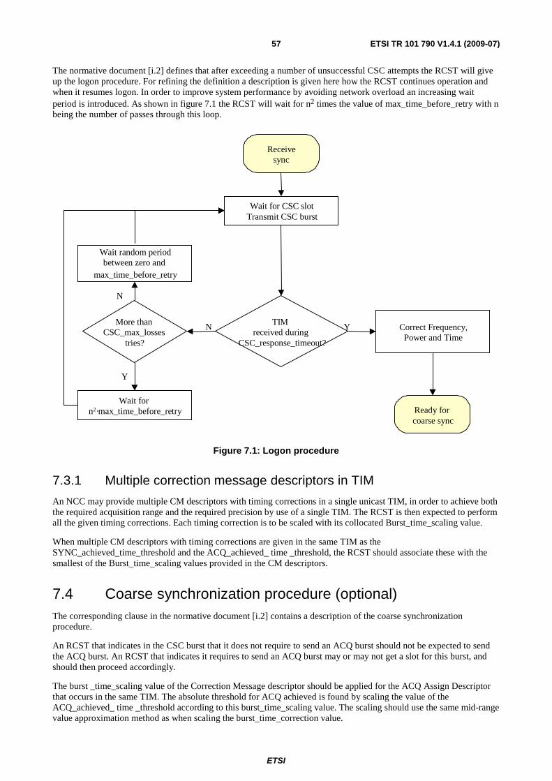
ETSI
ETSI TR 101 790 V1.4.1 (2009-07) 57
The normative document [i.2] defines that after exceeding a number of unsuccessful CSC attempts the RCST will give up the logon procedure. For refining the definition a description is given here how the RCST continues operation and when it resumes logon. In order to improve system performance by avoiding network overload an increasing wait period is introduced. As shown in figure 7.1 the RCST will wait for n2 times the value of max_time_before_retry with n being the number of passes through this loop.
Receivesync
Wait for CSC slotTransmit CSC burst
TIMreceived during
CSC_response_timeout?
More thanCSC_max_losses
tries?
Wait random periodbetween zero and
max_time_before_retry
N Y Correct Frequency,Power and Time
Y
N
Ready forcoarse sync
Wait forn2·max_time_before_retry
Figure 7.1: Logon procedure
7.3.1 Multiple correction message descriptors in TIM
An NCC may provide multiple CM descriptors with timing corrections in a single unicast TIM, in order to achieve both the required acquisition range and the required precision by use of a single TIM. The RCST is then expected to perform all the given timing corrections. Each timing correction is to be scaled with its collocated Burst_time_scaling value.
When multiple CM descriptors with timing corrections are given in the same TIM as the SYNC_achieved_time_threshold and the ACQ_achieved_ time _threshold, the RCST should associate these with the smallest of the Burst_time_scaling values provided in the CM descriptors.
7.4 Coarse synchronization procedure (optional) The corresponding clause in the normative document [i.2] contains a description of the coarse synchronization procedure.
An RCST that indicates in the CSC burst that it does not require to send an ACQ burst should not be expected to send the ACQ burst. An RCST that indicates it requires to send an ACQ burst may or may not get a slot for this burst, and should then proceed accordingly.
The burst _time_scaling value of the Correction Message descriptor should be applied for the ACQ Assign Descriptor that occurs in the same TIM. The absolute threshold for ACQ achieved is found by scaling the value of the ACQ_achieved_ time _threshold according to this burst_time_scaling value. The scaling should use the same mid-range value approximation method as when scaling the burst_time_correction value.
ETSI
ETSI TR 101 790 V1.4.1 (2009-07) 58
7.5 Fine synchronization procedure (optional) The corresponding clause in the normative document [i.2] contains a description of the fine synchronization procedure.
The fine synch procedure is considered mandatory for the RCST and optional for the NCC.
The burst _time_scaling value of the Correction Message descriptor should be applied for the SYNC Assign descriptor that occurs in the same unicast TIM. The absolute threshold for SYNC achieved is found by scaling the value of the SYNC_achieved_time_threshold according to this burst_time_scaling value. The scaling should use the same mid-range value approximation method as when scaling the burst_time_correction value.
The RCST should accept update of the SYNC_achieved_time_threshold received in successive TIMs after the logon TIM. This may be utilised by an NCC to increase the precision of the SYNC_achieved_time_threshold if this was not given with sufficient precision in the logon TIM.
7.6 Synchronization maintenance procedure The corresponding clause in the normative document [i.2] contains a description of the synchronization maintenance procedure.
The RCST should scale the burst_time_correction value given in CMT according to the burst_time_ scaling value related to the RCST by the same CMT. Despite what is indicated in [i.2] for the threshold values, it is adviced against that the burst_time_correction value of the CMT is compared directly with values of the ACQ_achieved_time_threshold and the SYNC_achieved_time_threshold respectively, as these may relate to a different scaling value. Each value should be scaled according to its respective burst_time_scaling value before being used in a comparison.
7.7 Logoff procedure Typical values for the triggers of abnormal log-off as defined in the corresponding clause of [i.2] may be:
• NCR not received for a period of 6 seconds.
• CMT burst correction not received for 3 consecutive SYNCs.
8 Control and management For optional Type B RCSTs, if capacity request mechanisms can be in conflict with ATM features, then these mechanisms can be disabled by the NCC and not used on the satellite network.
8.1 Protocol stack
8.1.1 Transparent system
The protocol stack for a transparent system is described in [i.2].
8.1.2 Regenerative system
In case of fully-regenerative RSMS (OBP with/without on board switching), the on board processor will provide data de-capsulation of the uplink streams, followed by encapsulation and frame formatting into downlink transport streams, which are identical to DVB-RCS forward link streams (see also table 4.1).
8.2 RCST addressing The Group_ID is probably the same on two consecutive sessions.
ETSI
ETSI TR 101 790 V1.4.1 (2009-07) 59
Group_ID: The Group_ID was introduced to reduce the signalling load on the forward link. A unique TBTP is applicable to a group of terminals. The network operator may perform Group_ID grouping based on the subscriber profiles and criteria such as:
• RCSTs of similar transmission capabilities are grouped together (i.e. same maximum transmission data rate, RCSTs of like ACQ capabilities).
• Terminals belonging to the same SMATV installation (These terminals will share the ODU and, thus, the return (uplink) frequency. NCC should handle these terminals as a group).
• RCSTs belonging to different Service Providers are given different Group_IDs.
• RCSTs having similar subscriber profiles.
• RCSTs of similar capacity needs and expected traffic patterns.
Interactive Network ID and Population ID: during installation the installer enters for the Interactive Network ID and the Population ID values that the network operator has assigned. The terminal uses the values for accessing the forward link signalling as defined in the normative document [i.1]. At a later point in time the values can be changed by an authorized installer or remotely by the NCC using the optional SNMP mechanism.
During logon the RCST is assigned to a specific group and superframe by the field Group_ID of the Logon Initialize Descriptor and the field Superframe_ID of the Satellite Return Link Descriptor. The TBTP, which assigns time slots to terminals, is sorted by Group_ID but not by Superframe_ID. Time slot assignment is on a superframe basis and valid for a specific repetition of the superframe. This gives the impression that all RCSTs of a group will have to belong to the same superframe. This is not the case if superframes and their repetitions have the same duration and start time. Then the superframe count in the TBTP applies to all the superframes that RCSTs of a group belong to.
8.3 Forward link signalling Note that if the NCC calculates time offset due to RCST-to-satellite range the SPT need not be transmitted.
The accessing of the forward link signalling is described in clause 8.5.5.11 in EN 301 790 [i.2]. It is recommended to refer to figure 35 of EN 301 790 [i.2] when reading the extra explanations that are provided here.
Information about the Satellite Interactive Network will be conveyed in a RCS Map Table (RMT). One RMT will be available per satellite network (orig_network_id). The terminal will be able to find the RMT by looking for a linkage descriptor of linkage type RCS Map (0x07) in the NIT on the start-up transport stream. Like all linkage descriptors, it contains the TS_id and the service_id for the service (RCS Map) that it links to. The NIT will contain a loop over transport streams, where for each TS multiple descriptors can be included. The satellite delivery system descriptor allows the terminal to tune to the transport stream that carries the RMT by giving information on the physical properties of the stream (such as frequency, polarization and symbol rate). On this stream, the terminal will find the PID that carries the RMT by using the PAT and PMT with the service_id from the RCS Map linkage descriptor.
The RMT has the same syntax as the NIT, which means that it can provide linkage descriptors and a loop over transport streams. Of course, the RMT will not use the default NIT PID (0x0010). The terminal will look for linkage descriptors of linkage type RCS FLS (0x81) to find the TS_id and service_id for the Forward Link Signalling service it should use. When the network uses multiple RCS FLS, the terminal has to search for its population_id in the private data part of the RCS FLS linkage descriptors. The terminal will select the RCS FLS linkage descriptor that contains its population_id. In the loop over transport streams, the terminal will then extract all relevant TS related information. This includes the satellite forward link and satellite return link descriptor. The satellite forward link descriptor is an enhanced satellite delivery descriptor, that also includes some extra information about the network's usage of the forward link (see clause 8.5.5.10.11 in EN 301 790 [i.2]). In early implementations, where terminals will not support the parallel reception of multiple forward links, there will be only one such descriptor (link_usage = '000' - combined signalling/data link). The satellite return link descriptor provides such information as the superframe_id and the transmit centre frequency offset, that the terminal needs to know in order to be able to use the return link efficiently.
ETSI
ETSI TR 101 790 V1.4.1 (2009-07) 60
The terminal will then finally tune to the transport stream that carries its data and signalling. To find the RCS specific signalling, it will find the PMT for the RCS specific signalling by using the PAT and PMT. In the FLS PMT, the terminal will be told in what PIDs the RCS tables and TIMs are carried and which PID is used for the NCR. The terminal can then load all relevant information from SCT, FCT, TCT and SPT, extract the 27 MHz reference from the NCR and select a suitable CSC in the superframe that matches the superframe_id from the satellite return link descriptor. When the CSC is received by the NCC, and the terminal is authenticated successfully, the terminal will get a TIM that contains among other things the group_id and logon_id. From that time on, the terminal can get slot allocations and correction messages through TBTP and CMT.
More information on frame definitions and the use of group_id and logon_id can be found in clauses 6.7 and 8.2 of the present document.
The slot type used in the CMT table and correction message descriptor is intended to indicate on which type of burst the measure was performed. First implementations of this mechanism are expected to use only the SYNC bursts.
The sync_repeat_period of the sync_assign_descriptor is intended to indicate the number of superframes between 2 SYNC assignments. For example, SYNC_repeat_period = 0 means that the SYNC slot is assigned on each superframe, SYNC_repeat_period = 1 means that two superframes containing the SYNC slot assignment are separated by 1 superframe that does not have the SYNC slot assigned, a SYNC_repeat_period = 2 means that two superframes containing the SYNC slot assignment are separated by 2 superframes that do not have the SYNC slot assigned.
8.3.1 Repetition rates
The normative document [i.2] indicated that the TBTP will be updated every superframe, or equivalently, for each increment of the "superframe_count" parameter.
When the superframe duration is long (its definition allows superframes to be as long as 93,2 s), an update rate of once per superframe would lead to unacceptable response times for the DVB-RCS system. This potential problem is remedied by observing that the definition of the TBTP does not preclude it from being transmitted several times per increment of the "superframe_count" parameter. In such a scheme, consecutive TBTPs contain the same "superframe_count" value, but different "frame_number" values. For example, the first TBTP could use "frame_number" values 1-8, the second TBTP could use frame numbers from 9-16 and so on. Note, however, that the "frame_number" values do not necessarily have to be consecutive numbers.
Similarly, if the frames themselves are long in duration, they too could possibly be split up into multiple TBTP assignments. In this case, the TBTPs would contain the same "superframe_count" and "frame_number" parameter values, but would differ in their "start_slot" parameter values.
Although difficult to pinpoint an exact value, a general guideline is to issue the TBTP associated with a particular "superframe_id" multiple times per second, so that this latency does not noticeably degrade the system response time.
In order to avoid ambiguity, an SCT with updated superframe_start_time and superframe_counter values should be sent
out at least every ⎭⎬⎫
⎩⎨⎧
2
____,
2
___min
timearoundwrapcountersuperframetimearoundwrapNCR.
This will guarantee that the RCST can unambiguously decide whether the SCT defines a superframe in the past or the future by looking at the start time and current time alone. It will also guarantee that the starttime of a specific superframe can be calculated by unambiguously without considering wrap-around of the superframe counter.
8.3.2 DVB RCS SI table updates
An update of the RCS SI tables is indicated by the use of the current_next_indicator and version_number fields of the SI section header. The Table Update Descriptor may be used to inform the RCST that there is an upcoming change to one of these tables. For the SI tables used for frame composition, SCT, FCT and TCT, the start time parameters of the SCT (superframe_start_time_base, and superframe_start_time_ext) should be used to invoke the transition from current to new tables.
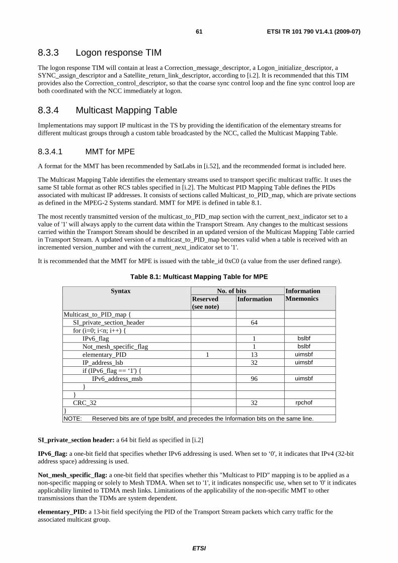
ETSI
ETSI TR 101 790 V1.4.1 (2009-07) 61
8.3.3 Logon response TIM
The logon response TIM will contain at least a Correction_message_descriptor, a Logon_initialize_descriptor, a SYNC_assign_descriptor and a Satellite_return_link_descriptor, according to [i.2]. It is recommended that this TIM provides also the Correction_control_descriptor, so that the coarse sync control loop and the fine sync control loop are both coordinated with the NCC immediately at logon.
8.3.4 Multicast Mapping Table
Implementations may support IP multicast in the TS by providing the identification of the elementary streams for different multicast groups through a custom table broadcasted by the NCC, called the Multicast Mapping Table.
8.3.4.1 MMT for MPE
A format for the MMT has been recommended by SatLabs in [i.52], and the recommended format is included here.
The Multicast Mapping Table identifies the elementary streams used to transport specific multicast traffic. It uses the same SI table format as other RCS tables specified in [i.2]. The Multicast PID Mapping Table defines the PIDs associated with multicast IP addresses. It consists of sections called Multicast_to_PID_map, which are private sections as defined in the MPEG-2 Systems standard. MMT for MPE is defined in table 8.1.
The most recently transmitted version of the multicast_to_PID_map section with the current_next_indicator set to a value of '1' will always apply to the current data within the Transport Stream. Any changes to the multicast sessions carried within the Transport Stream should be described in an updated version of the Multicast Mapping Table carried in Transport Stream. A updated version of a multicast_to_PID_map becomes valid when a table is received with an incremented version_number and with the current_next_indicator set to '1'.
It is recommended that the MMT for MPE is issued with the table_id 0xC0 (a value from the user defined range).
Table 8.1: Multicast Mapping Table for MPE
No. of bits Syntax Reserved (see note)
Information Information Mnemonics
Multicast_to_PID_map SI_private_section_header 64 for (i=0; i<n; i++) IPv6_flag 1 bslbf Not_mesh_specific_flag 1 bslbf elementary_PID 1 13 uimsbf IP_address_lsb 32 uimsbf if (IPv6_flag == ‘1') IPv6_address_msb 96 uimsbf CRC_32 32 rpchof NOTE: Reserved bits are of type bslbf, and precedes the Information bits on the same line.
SI_private_section header: a 64 bit field as specified in [i.2]
IPv6_flag: a one-bit field that specifies whether IPv6 addressing is used. When set to ‘0', it indicates that IPv4 (32-bit address space) addressing is used.
Not_mesh_specific_flag: a one-bit field that specifies whether this "Multicast to PID" mapping is to be applied as a non-specific mapping or solely to Mesh TDMA. When set to '1', it indicates nonspecific use, when set to '0' it indicates applicability limited to TDMA mesh links. Limitations of the applicability of the non-specific MMT to other transmissions than the TDMs are system dependent.
elementary_PID: a 13-bit field specifying the PID of the Transport Stream packets which carry traffic for the associated multicast group.

ETSI
ETSI TR 101 790 V1.4.1 (2009-07) 62
IP_address_lsb: a 32-bit field that specifies the 32 least significant bits of a multicast group IP address applied in packets with the associated elementary_PID.
IPv6_address_msb: a 96-bit field that specifies the 96 most significant bits of a multicast group IPv6 address applied in packets with the associated elementary_PID.
CRC_32: a 32-bit field that contains the CRC value that gives a zero output of the registers in the decoder defined in Annex B of EN 300 468 [i.35] after processing the entire private section.
8.3.4.2 MMT for VC-MUX
Implementations may support IP multicast on links using ATM formatting by providing the identification of the VCC for different multicast groups through a custom table broadcasted by the NCC, called the Multicast Mapping Table.
The Multicast Mapping Table identifies the elementary streams used to transport specific multicast traffic. It uses the same SI table format as other RCS tables specified in [i.2]. The Multicast VCC Mapping Table defines the VCCs associated with multicast IP addresses. It consists of sections called Multicast_to_VCC_map, which are private sections as defined in the MPEG-2 Systems standard. MMT for VC-MUX is defined in table 8.2.
The most recently transmitted version of the multicast_to_VCC_map section with the current_next_indicator set to a value of '1' will apply to the current data within the Transport Stream. Any changes to the multicast sessions carried within the Transport Stream should be described in an updated version of the Multicast Mapping Table carried in Transport Stream. A updated version of a multicast_to_VCC_map becomes valid when a table is received with an incremented version_number and with the current_next_indicator set to ‘1'.
It is recommended that the MMT for ATM is issued with the table_id 0xD0 (a value from the user defined range).
Table 8.2: Multicast Mapping Table for VC-MUX
No. of bits Syntax Reserved (see note)
Information Information Mnemonics
Multicast_to_VCC_map SI_private_section_header 64 for (i=0; i<n; i++) IPv6_flag 7 1 bslbf vccVpi 8 bslbf vccVci 16 uimsbf IP_address_lsb 32 uimsbf if (IPv6_flag == ‘1') IPv6_address_msb 96 uimsbf CRC_32 32 rpchof NOTE: Reserved bits are of type bslbf, and precedes the Information bits on the same line.
SI_private_section header: a 64 bit field as specified in [i.2].
IPv6_flag: a one-bit field that specifies whether IPv6 addressing is used. When set to ‘0', it indicates that IPv4 (32-bit address space) addressing is used.
vccVpi: a 8-bit field specifying the VCC VPI of the ATM packets which carry the associated multicast data.
vccVci: a 16-bit field specifying the VCC VCI of the ATM packets which carry the associated multicast data.
IP_address_lsb: a 32-bit field that specifies the 32 least significant bits of a multicast group IP address applied in packets with the associated elementary_PID.
IPv6_address_msb: a 96-bit field that specifies the 96 most significant bits of a multicast group IPv6 address applied in packets with the associated elementary_PID.
CRC_32: a 32-bit field that contains the CRC value that gives a zero output of the registers in the decoder defined in annex B of EN 300 468 [i.35] after processing the entire private section.

ETSI
ETSI TR 101 790 V1.4.1 (2009-07) 63
8.3.5 Other FL messages for network management (optional)
A design that provides additional functionality with SNMP can be found in clause 8.6.
8.4 Return Link Signalling The return link signalling specified in [i.2] serves these four functional groups:
• System logon and burst synch acquisition.
• Maintenance of burst synchronisation.
• Unit control and management.
• Resource control.
8.4.1 Typically use of Return Link Signalling
It is highly recommended that both the RCST and the GW supports signaling in the regularly assigned dedicated synch slots that are allocated for synch maintenance.
It is highly recommended that both the RCST and the GW supports signalling in TRF slots, for the ATM mode as well as the MPEG mode as applicable, as this is essential for performance.
Contention based mini-slots may be in use as a supplement to dedicated mini-slots and in-band signalling.
It is not recommended to rely on DULM if this is not required by additional specifications, as implementations cannot generally be expected to support the use of DULM.
The channel_ID associated with a capacity request in systems operated without dynamic connectivity control is typically used as an indication solely of the RC of the associated traffic as described in clause6.8.
8.4.2 On board processing of Return Link Signalling
In fully regenerative RSMS (OBP with/without on board switching), the onboard processor will provide some functions which would be otherwise provided by the NCC. Therefore, the OBP has an active role in the return link synchronization procedure and link control and monitoring.
In particular the following control and management signalling messages may be extracted by the satellite OBP and forwarded as appropriate:
• Link monitoring information (time, frequency, power measurements) in the case CMT is not directly provided on-board.
• CSC messages.
• SAC messages (resource request and M&C messages) transmitted in SYNC mini-slots (in the case of mini-slot method) or piggybacked with traffic data (in the case of prefix method), in case resources management is not performed onboard.
The OBP may process return link signalling messages coming from terminals and generate directly some SI tables (CMT, TBTP). Alternatively, it may forward them to the NCC. Information exchange between the OBP and NCC can be implemented in several different ways. Annex K describes one implementation of the multiplexing of this information with forward link signalling. This method may or not be used in regenerative systems and is therefore optional.
8.4.3 Other RL messages for network management (optional)
A design that provides additional functionality with SNMP can be found in clause 8.6.
An RCST may support signalling of a Route_ID as specified in [i.2]. The use of the Route_ID is considered optional and system dependent.
ETSI
ETSI TR 101 790 V1.4.1 (2009-07) 64
8.5 Coding of SI for forward link signalling
8.5.1 Table definition
The TBTP should be transmitted in the proper order (consecutive frames are sent one after each other). TBTP should not be sent fragmented (for example a part of frame n, then a part of frame m, then again a part of frame n and so on).
8.5.1.1 Timeslot Composition Table (TCT)
Preamble_Length: For the CSC, SYNC and TRF bursts, this parameter is used to communicate unambiguously the length of the preamble sequence that precedes the encoded information bits. When used with the ACQ burst, however, this parameter indicates the combined length in symbols of both the preamble and the special frequency sequence, as illustrated in figure 9 of the normative document [i.2].
For an RCST, there is no particular need to be able to differentiate between the two segments of the ACQ burst. To a Traffic Gateway, on the other hand, the situation is different. Thus, in order to fully exploit the capabilities an ACQ burst offers, the Traffic Gateway should know the length of the individual segments of the ACQ burst. If applicable - i.e. if the ACQ burst is used - then this information should be communicated from the NCC to the Traffic Gateway.
8.5.1.2 Terminal Burst Time Plan (TBTP)
The assignment_type field is used to specify the type of allocation which is granted to the RCST. In most networks, RCSTs transmit in all assigned time slots, even when they have no actual traffic to send. Some networks may prefer that RCST's generally do not transmit in this case. In these systems, the reserved value of the assignment_type field can be used exceptionally to force transmission in a burst (see clause 6.8).
Assignment types as defined in [i.2] are listed below:
• 00: One time assignment: the slot(s) is (are) assigned only for this superframe.
• 01: Repeating assignment: the slot(s) is (are) assigned in all superframes after the current one, until released.
• 10: Assignment release: the slot(s) previously allocated are no longer useable by the RCST.
• 11: Forced_transmission one time assignment (system dependent): the RCST is forced to transmit in the burst(s), even if it has no traffic to send.
It should be noted that the "forced_transmission" uses the combination "11", which is currently a "reserved value" in the normative document [i.2], and is thus considered a system dependent mechanism.
It is generally adviced against using ‘repeating assignment' due to the lack of a reliable mechanism to assure that collisions will not occur, as explicit open-loop ‘assignment release' is considered a too unreliable mechanism. For this reason it cannot be assumed that all implementations support ‘repeating assignment'. Any RCST should support the ‘one time assignment' type.
8.5.2 DSM-CC Private Section Header
The DSM-CC section is specified in [i.51]. A DSM-CC section can contain private data, and [i.34] specifies that this private data can be used to transport MPE, using a specific header extension. TIM is specified in [i.2] as a specialized type of the private sections specified in [i.50], and a header extension is specified for TIM, termed 'DSM-CC Private Section Header' (the TIM header specification resembles the specification of the MPE header, which is an extension of the DSM-CC section header specified in [i.51]). Note that even if the MPE header and the TIM header have congruent data structures they differ by the allowed range of the section_length, which limits the total section size for TIM to 1 024 bytes.
8.6 SNMP (optional) It is recommended that the RCST supports SNMP/UDP/IP on its Satellite and Ethernet interfaces and act as an SNMP agent/client. The RCST should support SNMPv2c as specified in [i.25] and [i.19].

ETSI
ETSI TR 101 790 V1.4.1 (2009-07) 65
It is recommended that the following MIB modules are implemented:
1) MIB-II [i.56].
2) DVB-RCS MIB.
The DVB-RCS MIB is specified by SatLabs in [i.52].
9 Security, identity and encryption Clause 9.4 of the normative document [i.2] describes an optional security mechanism, which provides link layer security. An example for a security and authentication concept, which takes into account the common practice in the Internet environment, can be found in annex G.
An example of end user authentication using RADIUS between RCST and NCC/ISP can be found in annex G.
10 RCST implementation guidelines
10.1 Architecture The RCST does typically comply with the architecture outlined in figure 10.1. An RCST may conceptually consist of the Outdoor Unit (ODU), the Interfacility-Link (IFL), and the Indoor Unit (IDU).
The ODU is composed of the following subsystems: Antenna Subsystem (ANT), Transceiver (TRx), and Mechanical Subsystem (MECH). The Interfacility Link (IFL) is a cable assembly, which interconnects the IDU with the ODU.
The ANT consists of the reflector(s) and a combined transmit/receive feed. Optionally the ANT may also include an additional receive feed for receiving from a satellite at a different orbital location. The receive (Rx) part of the TRx includes the Low Noise amplifier(s), frequency downconversion and polarization as well as frequency band selection. The transmit part (Tx) of the TRx performs frequency upconversion as well as power amplification. The MECH attaches the ODU to a firm structure and provides means for accurate pointing.
The IDU consists of the following subsystems: Network Interface Unit (NIU), User Interface Unit (UIU), Power Supply Unit (PSU) and Packaging. These subsystems can be implemented e.g. in a standalone IDU, within a desktop PC or Set-Top Box.
The UIU is the interface between all receive/transmit elements of the IDU and the user device.
The NIU is constituted of at least one forward link receiver for reception of the forward link signalling (and the Traffic sent on the same Transport Stream), a transmit chain for transmission of Traffic and forward link signalling to the ODU, and all the necessary controlling elements. If only one forward link receiver is available Traffic and forward link signalling will be received from the same DVB-S Transport Stream or the same DVB-S2 Physical Layer Frame stream. Additional forward link receivers allow the transmission of Traffic and forward link signalling on different DVB-S transport streams or DVB-S2 Physical Layer Frame streams. This results in significant improvement of operational flexibility and should be the preferred solution. The number of available forward link receivers is a parameter exchanged between the RCST and the NCC during RCST logon.
The conceptual split between IDU and ODU functionality as described above, and specified in the present document represents only one possible separation of functions. There may be also different approaches providing the same overall functionality.
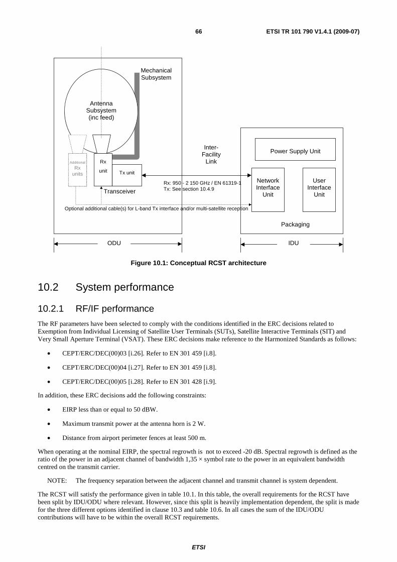
ETSI
ETSI TR 101 790 V1.4.1 (2009-07) 66
Rx
unit Tx unit
Additional Rx
units Network Interface
Unit
User
Interface Unit
Power Supply Unit
Packaging
Inter-
Facility Link
Rx: 950 - 2 150 GHz / EN 61319-1 Tx: See section 10.4.9
Mechanical Subsystem
Optional additional cable(s) for L-band Tx interface and/or multi-satellite reception
Antenna
Subsystem (inc feed)
Transceiver
ODU IDU
Figure 10.1: Conceptual RCST architecture
10.2 System performance
10.2.1 RF/IF performance
The RF parameters have been selected to comply with the conditions identified in the ERC decisions related to Exemption from Individual Licensing of Satellite User Terminals (SUTs), Satellite Interactive Terminals (SIT) and Very Small Aperture Terminal (VSAT). These ERC decisions make reference to the Harmonized Standards as follows:
• CEPT/ERC/DEC(00)03 [i.26]. Refer to EN 301 459 [i.8].
• CEPT/ERC/DEC(00)04 [i.27]. Refer to EN 301 459 [i.8].
• CEPT/ERC/DEC(00)05 [i.28]. Refer to EN 301 428 [i.9].
In addition, these ERC decisions add the following constraints:
• EIRP less than or equal to 50 dBW.
• Maximum transmit power at the antenna horn is 2 W.
• Distance from airport perimeter fences at least 500 m.
When operating at the nominal EIRP, the spectral regrowth is not to exceed -20 dB. Spectral regrowth is defined as the ratio of the power in an adjacent channel of bandwidth 1,35 × symbol rate to the power in an equivalent bandwidth centred on the transmit carrier.
NOTE: The frequency separation between the adjacent channel and transmit channel is system dependent.
The RCST will satisfy the performance given in table 10.1. In this table, the overall requirements for the RCST have been split by IDU/ODU where relevant. However, since this split is heavily implementation dependent, the split is made for the three different options identified in clause 10.3 and table 10.6. In all cases the sum of the IDU/ODU contributions will have to be within the overall RCST requirements.
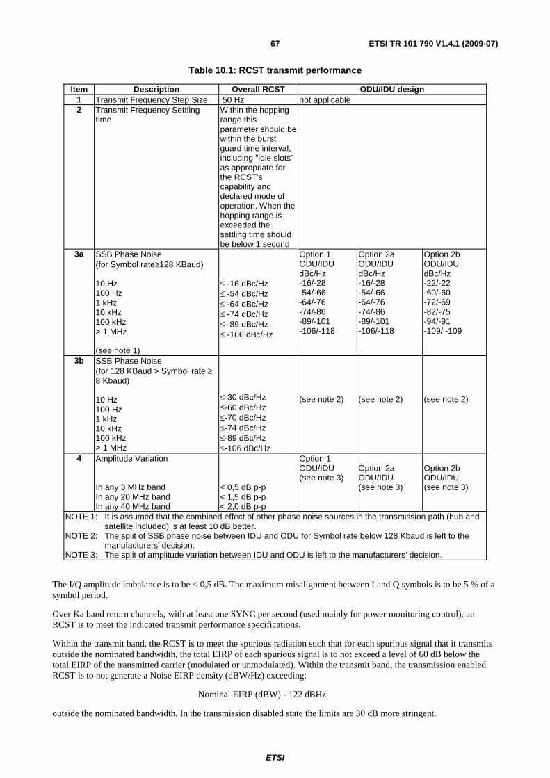
ETSI
ETSI TR 101 790 V1.4.1 (2009-07) 67
Table 10.1: RCST transmit performance
Item Description Overall RCST ODU/IDU design 1 Transmit Frequency Step Size 50 Hz not applicable 2 Transmit Frequency Settling
time Within the hopping range this parameter should be within the burst guard time interval, including "idle slots" as appropriate for the RCST's capability and declared mode of operation. When the hopping range is exceeded the settling time should be below 1 second
3a SSB Phase Noise (for Symbol rate≥128 KBaud) 10 Hz 100 Hz 1 kHz 10 kHz 100 kHz > 1 MHz (see note 1)
≤ -16 dBc/Hz ≤ -54 dBc/Hz ≤ -64 dBc/Hz ≤ -74 dBc/Hz ≤ -89 dBc/Hz ≤ -106 dBc/Hz
Option 1 ODU/IDU dBc/Hz -16/-28 -54/-66 -64/-76 -74/-86 -89/-101 -106/-118
Option 2a ODU/IDU dBc/Hz -16/-28 -54/-66 -64/-76 -74/-86 -89/-101 -106/-118
Option 2b ODU/IDU dBc/Hz -22/-22 -60/-60 -72/-69 -82/-75 -94/-91 -109/ -109
3b SSB Phase Noise (for 128 KBaud > Symbol rate ≥ 8 Kbaud) 10 Hz 100 Hz 1 kHz 10 kHz 100 kHz > 1 MHz
≤-30 dBc/Hz ≤-60 dBc/Hz ≤-70 dBc/Hz ≤-74 dBc/Hz ≤-89 dBc/Hz ≤-106 dBc/Hz
(see note 2)
(see note 2)
(see note 2)
4 Amplitude Variation In any 3 MHz band In any 20 MHz band In any 40 MHz band
< 0,5 dB p-p < 1,5 dB p-p < 2,0 dB p-p
Option 1 ODU/IDU (see note 3)
Option 2a ODU/IDU (see note 3)
Option 2b ODU/IDU (see note 3)
NOTE 1: It is assumed that the combined effect of other phase noise sources in the transmission path (hub and satellite included) is at least 10 dB better.
NOTE 2: The split of SSB phase noise between IDU and ODU for Symbol rate below 128 Kbaud is left to the manufacturers' decision.
NOTE 3: The split of amplitude variation between IDU and ODU is left to the manufacturers' decision.
The I/Q amplitude imbalance is to be < 0,5 dB. The maximum misalignment between I and Q symbols is to be 5 % of a symbol period.
Over Ka band return channels, with at least one SYNC per second (used mainly for power monitoring control), an RCST is to meet the indicated transmit performance specifications.
Within the transmit band, the RCST is to meet the spurious radiation such that for each spurious signal that it transmits outside the nominated bandwidth, the total EIRP of each spurious signal is to not exceed a level of 60 dB below the total EIRP of the transmitted carrier (modulated or unmodulated). Within the transmit band, the transmission enabled RCST is to not generate a Noise EIRP density (dBW/Hz) exceeding:
Nominal EIRP (dBW) - 122 dBHz
outside the nominated bandwidth. In the transmission disabled state the limits are 30 dB more stringent.
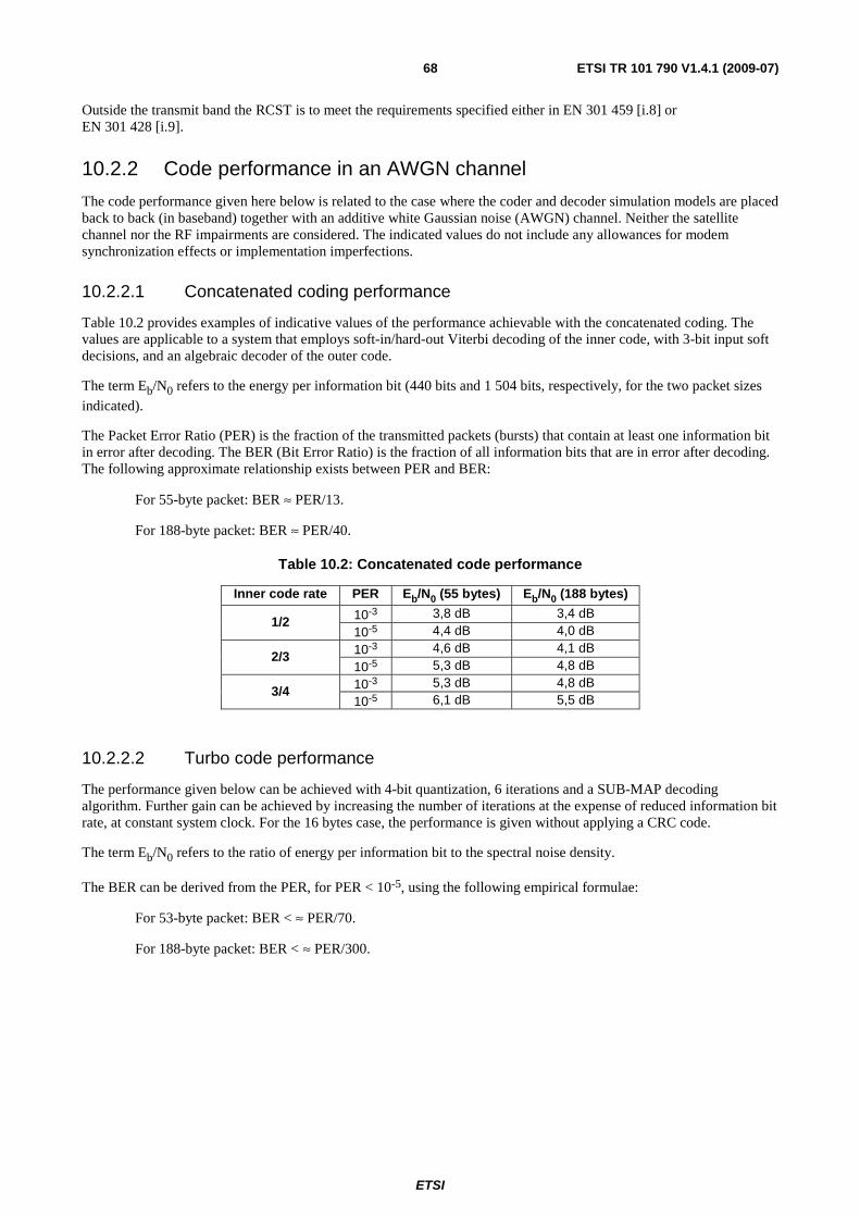
ETSI
ETSI TR 101 790 V1.4.1 (2009-07) 68
Outside the transmit band the RCST is to meet the requirements specified either in EN 301 459 [i.8] or EN 301 428 [i.9].
10.2.2 Code performance in an AWGN channel
The code performance given here below is related to the case where the coder and decoder simulation models are placed back to back (in baseband) together with an additive white Gaussian noise (AWGN) channel. Neither the satellite channel nor the RF impairments are considered. The indicated values do not include any allowances for modem synchronization effects or implementation imperfections.
10.2.2.1 Concatenated coding performance
Table 10.2 provides examples of indicative values of the performance achievable with the concatenated coding. The values are applicable to a system that employs soft-in/hard-out Viterbi decoding of the inner code, with 3-bit input soft decisions, and an algebraic decoder of the outer code.
The term Eb/N0 refers to the energy per information bit (440 bits and 1 504 bits, respectively, for the two packet sizes indicated).
The Packet Error Ratio (PER) is the fraction of the transmitted packets (bursts) that contain at least one information bit in error after decoding. The BER (Bit Error Ratio) is the fraction of all information bits that are in error after decoding. The following approximate relationship exists between PER and BER:
For 55-byte packet: BER ≈ PER/13.
For 188-byte packet: BER ≈ PER/40.
Table 10.2: Concatenated code performance
Inner code rate PER Eb/N0 (55 bytes) Eb/N0 (188 bytes)
10-3 3,8 dB 3,4 dB 1/2
10-5 4,4 dB 4,0 dB
10-3 4,6 dB 4,1 dB 2/3
10-5 5,3 dB 4,8 dB
10-3 5,3 dB 4,8 dB 3/4
10-5 6,1 dB 5,5 dB
10.2.2.2 Turbo code performance
The performance given below can be achieved with 4-bit quantization, 6 iterations and a SUB-MAP decoding algorithm. Further gain can be achieved by increasing the number of iterations at the expense of reduced information bit rate, at constant system clock. For the 16 bytes case, the performance is given without applying a CRC code.
The term Eb/N0 refers to the ratio of energy per information bit to the spectral noise density.
The BER can be derived from the PER, for PER < 10-5, using the following empirical formulae:
For 53-byte packet: BER < ≈ PER/70.
For 188-byte packet: BER < ≈ PER/300.
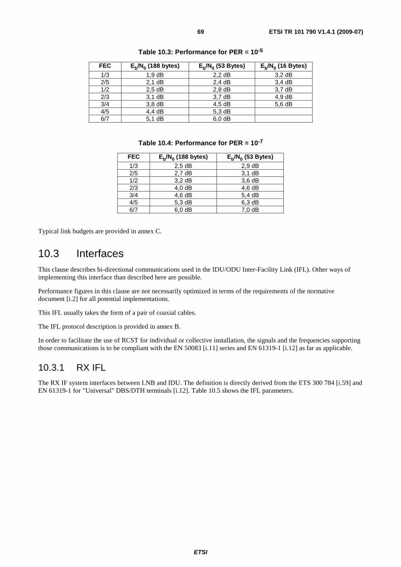
ETSI
ETSI TR 101 790 V1.4.1 (2009-07) 69
Table 10.3: Performance for PER = 10-5
FEC Eb/N0 (188 bytes) Eb/N0 (53 Bytes) Eb/N0 (16 Bytes)
1/3 1,9 dB 2,2 dB 3,2 dB 2/5 2,1 dB 2,4 dB 3,4 dB 1/2 2,5 dB 2,8 dB 3,7 dB 2/3 3,1 dB 3,7 dB 4,9 dB 3/4 3,8 dB 4,5 dB 5,6 dB 4/5 4,4 dB 5,3 dB 6/7 5,1 dB 6,0 dB
Table 10.4: Performance for PER = 10-7
FEC Eb/N0 (188 bytes) Eb/N0 (53 Bytes)
1/3 2,5 dB 2,9 dB 2/5 2,7 dB 3,1 dB 1/2 3,2 dB 3,6 dB 2/3 4,0 dB 4,6 dB 3/4 4,6 dB 5,4 dB 4/5 5,3 dB 6,3 dB 6/7 6,0 dB 7,0 dB
Typical link budgets are provided in annex C.
10.3 Interfaces This clause describes bi-directional communications used in the IDU/ODU Inter-Facility Link (IFL). Other ways of implementing this interface than described here are possible.
Performance figures in this clause are not necessarily optimized in terms of the requirements of the normative document [i.2] for all potential implementations.
This IFL usually takes the form of a pair of coaxial cables.
The IFL protocol description is provided in annex B.
In order to facilitate the use of RCST for individual or collective installation, the signals and the frequencies supporting those communications is to be compliant with the EN 50083 [i.11] series and EN 61319-1 [i.12] as far as applicable.
10.3.1 RX IFL
The RX IF system interfaces between LNB and IDU. The definition is directly derived from the ETS 300 784 [i.59] and EN 61319-1 for "Universal" DBS/DTH terminals [i.12]. Table 10.5 shows the IFL parameters.

ETSI
ETSI TR 101 790 V1.4.1 (2009-07) 70
Table 10.5: IFL parameters
Parameter Value Unit Note Frequency scheme no spectral inversion IF frequency input range, low band See table [10.6] IF frequency input range, high band See table [10.6] IF impedance 75 Ohm Return loss LNB & modem > 8 dB Connector type F-type Connector & cable color code blue Cable loss @ 2 150 MHz < 40 dB/100m LNB band switch tone command according to EN 61319-1 [i.12] Low band selected 0,0 - 0,2 Vpp High band selected 0,4 - 0,8 Vpp
18 - 26 kHz
Polarization fixed linear, orthogonal with TX (see note) DC supply voltage 11 - 19 V on the LNB DC supply current < 300 mA NOTE: If dual-polarisation reception is supported then the voltage (13/17V) switching
command as specified in [i.12].
Typical IDU IFL frequency input ranges includes the ones shown in table 10.6.
Table 10.6: IFL Rx frequency
Band RF [GHz] LO [GHz] IF [MHz] C-Band 3,7 to 4,20 5,15 950 to 1 450 Kutoband - Low band 10,7 to 11,70 9,75 950 to 1 950 Kutoband - High band 11,7 to12,75 10,60 1 100 to 2 150 Ka-band 19,7 to 20,20 18,75 950 to 1 450
10.3.2 TX IFL
The TX IFL system interfaces between IDU and BUC. A single coaxial cable typically carries:
• The TX IF signal in L-band.
• The TX LO frequency reference signal.
• A low frequency sub-carrier for DiSEqC™ signaling.
• The DC power supplying the BUC.
In general L-band is recommended for all RCS terminals according to following scheme, with no spectral inversion, given in table 10.7.
Table 10.7: IFL Tx frequency
Band RF [GHz] LO [GHz] IF [MHz] Ku-band 14,00 - 14,50 13,05 950 - 1 450 Extended Ku-band 13,75 - 14,25 12,80 950 - 1 450 Full extended Ku-band 13,75 - 14,50 12,80 950 - 1 700 Ka-band 29,50 - 30,00 28,55 950 - 1 450
It might be desired to ease installation by having the IDU automatically set the IDU output level to compensate for different cable attenuations and BUC gains. It is then recommended to use measured RF power from the BUC supported by the protocol defined in annex B.
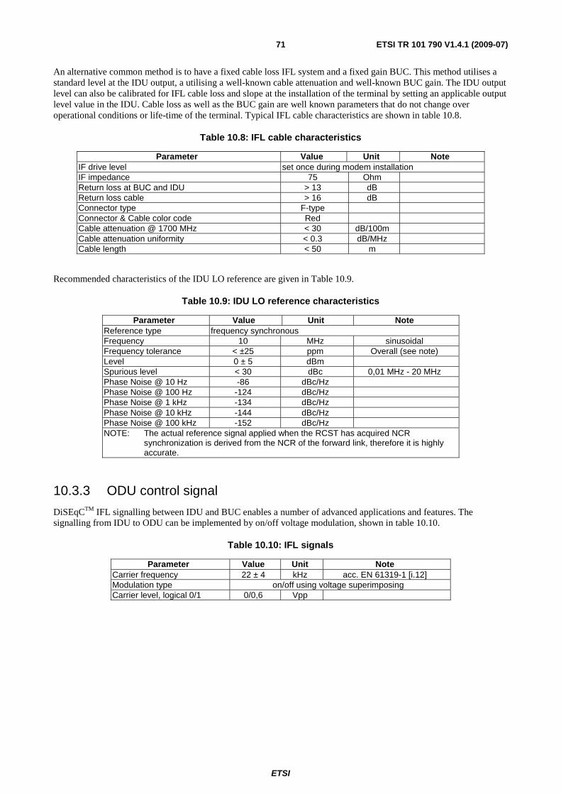
ETSI
ETSI TR 101 790 V1.4.1 (2009-07) 71
An alternative common method is to have a fixed cable loss IFL system and a fixed gain BUC. This method utilises a standard level at the IDU output, a utilising a well-known cable attenuation and well-known BUC gain. The IDU output level can also be calibrated for IFL cable loss and slope at the installation of the terminal by setting an applicable output level value in the IDU. Cable loss as well as the BUC gain are well known parameters that do not change over operational conditions or life-time of the terminal. Typical IFL cable characteristics are shown in table 10.8.
Table 10.8: IFL cable characteristics
Parameter Value Unit Note IF drive level set once during modem installation IF impedance 75 Ohm Return loss at BUC and IDU > 13 dB Return loss cable > 16 dB Connector type F-type Connector & Cable color code Red Cable attenuation @ 1700 MHz < 30 dB/100m Cable attenuation uniformity < 0.3 dB/MHz Cable length < 50 m
Recommended characteristics of the IDU LO reference are given in Table 10.9.
Table 10.9: IDU LO reference characteristics
Parameter Value Unit Note Reference type frequency synchronous Frequency 10 MHz sinusoidal Frequency tolerance < ±25 ppm Overall (see note) Level 0 ± 5 dBm Spurious level < 30 dBc 0,01 MHz - 20 MHz Phase Noise @ 10 Hz -86 dBc/Hz Phase Noise @ 100 Hz -124 dBc/Hz Phase Noise @ 1 kHz -134 dBc/Hz Phase Noise @ 10 kHz -144 dBc/Hz Phase Noise @ 100 kHz -152 dBc/Hz NOTE: The actual reference signal applied when the RCST has acquired NCR
synchronization is derived from the NCR of the forward link, therefore it is highly accurate.
10.3.3 ODU control signal
DiSEqCTM IFL signalling between IDU and BUC enables a number of advanced applications and features. The signalling from IDU to ODU can be implemented by on/off voltage modulation, shown in table 10.10.
Table 10.10: IFL signals
Parameter Value Unit Note Carrier frequency 22 ± 4 kHz acc. EN 61319-1 [i.12] Modulation type on/off using voltage superimposing Carrier level, logical 0/1 0/0,6 Vpp
ETSI
ETSI TR 101 790 V1.4.1 (2009-07) 72
10.3.3.1 Concept of the 22 kHz Pulse Width Keying (PWK) Bus
The low data rate communication between the IDU and the ODU is based on a 22 kHz PWK signal as used by DiSEqCTM [i.18]. The impedance of the bus at 22 kHz should be 15 Ω. A parallel inductor of 270 μH can be used to support a DC. power supply current. In this case a capacitor to ground should be supplied to shape the 22 kHz signal. The DC feeding point is grounded for 22 kHz with a capacitor. If a DC is not needed for powering peripheral devices, then in order to maintain correct operation of the DiSEqCTM bus, there should be a minimum of 10 V bias applied, but the inductor and capacitor can be omitted.
The control signal from every device on the bus is produced by a 43 mA current shunt producing a 650 mV signal which is monitored by every device. This amplitude of the DiSEqCTM carrier tone on the bus is normally too small to detect directly on a "TTL" or "CMOS" compatible pin on a microcontroller, so usually a "comparator" input, or a simple external (one-transistor) amplifier, is required. In any case, it is important not to make the input too sensitive to small-amplitude signals which may be "noise" or interference. It is recommended that the smallest amplitude normally detected is about 200 mV peak-peak. This can be achieved either with hysteresis (positive feedback applied around the comparator/amplifier) or with a DC bias offset (equivalent to about 100 mV) applied to the input of the amplifier/comparator. Hysteresis (if symmetrical) can maintain a reasonably constant 50 % duty cycle for the detected carrier tone, whilst the DC offset method may generate a less desirable asymmetric (pulse) waveform when the carrier amplitude approaches the lower limit.
All devices are connected in parallel on the bus and should therefore have a high impedance.

ETSI
ETSI TR 101 790 V1.4.1 (2009-07) 73
ODU
Rr
> 10 000 Ω
U22 kHz
RB = 15 Ω
LB = 270 μH
CB = 470 nF typically
Bias Voltage > 10 V
IDU1
Rr
> 10 000 Ω
U22 kHz
IDUn
Rr
> 10 000 Ω
U22 kHz
Cr
Cr
Cr
43 mA
43 mA
43 mA
Figure 10.2: 22 kHz PWK bus concept
The PWK circuit specification is given in table 10.11.
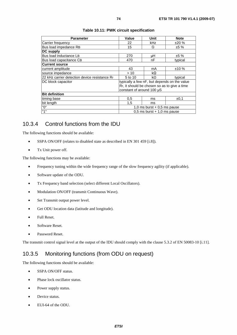
ETSI
ETSI TR 101 790 V1.4.1 (2009-07) 74
Table 10.11: PWK circuit specification
Parameter Value Unit Note Carrier frequency 22 kHz ±20 % Bus load impedance RB 15 Ω ±5 % DC supply Bus load inductance LB 270 μH ±5 % Bus load capacitance CB 470 nF typical Current source current amplitude 43 mA ±10 % source impedance > 10 kΩ 22 kHz carrier detection device resistance Rr 5 to 10 kΩ typical DC block capacitor typically a few nF, but depends on the value
Rr, it should be chosen so as to give a time constant of around 100 μS
Bit definition timing base 0,5 ms ±0,1 bit length 1,5 ms "0" 1,0 ms burst + 0,5 ms pause "1" 0,5 ms burst + 1,0 ms pause
10.3.4 Control functions from the IDU
The following functions should be available:
• SSPA ON/OFF (relates to disabled state as described in EN 301 459 [i.8]).
• Tx Unit power off.
The following functions may be available:
• Frequency tuning within the wide frequency range of the slow frequency agility (if applicable).
• Software update of the ODU.
• Tx Frequency band selection (select different Local Oscillators).
• Modulation ON/OFF (transmit Continuous Wave).
• Set Transmit output power level.
• Get ODU location data (latitude and longitude).
• Full Reset.
• Software Reset.
• Password Reset.
The transmit control signal level at the output of the IDU should comply with the clause 5.3.2 of EN 50083-10 [i.11].
10.3.5 Monitoring functions (from ODU on request)
The following functions should be available:
• SSPA ON/OFF status.
• Phase lock oscillator status.
• Power supply status.
• Device status.
• EUI-64 of the ODU.

ETSI
ETSI TR 101 790 V1.4.1 (2009-07) 75
NOTE: EUI-64 is a trademark of IEEE, it is intended to identify a single unique device independent of its functionality. The rules for allocation can be obtained from the IEEE.
• ODU manufacturing information.
The following functions may be available:
• ODU temperature information for compensation.
• ODU output power level for compensation.
• ODU RF calibration parameters for RF level detector compensation.
• LNB status (in the case the LNB or a part of the LNB is controlled by the ODU control bus).
• Get ODU location data (latitude and longitude).
• Authentication information exchange between the ODU and the IDU.
10.3.6 Control and Monitoring protocol description
The protocol description is provided in annex B.
10.4 ODU environmental conditions
10.4.1 Operational environment
There should be no significant degradation of the specified system and subsystem performance when operating under the following environmental conditions:
• Temperature: -30 °C to +50 °C.
• Solar Radiation: 500 W/m2 max.
• Humidity: 0 % to 100 % (condensing).
• Rain: up to 40 mm/h.
• Wind: up to 45 km/h.
The ODU mechanical construction should provide for that there are no random vibrations during wind conditions which cause any significant performance degradation.
10.4.2 Survival conditions
The ODU is allowed to degrade in performance, but should maintain pointing accuracy and suffer no permanent degradation under the following environmental conditions:
• Temperature: -40 °C to +60 °C.
• Solar Radiation: 1 000 W/m2.
• Humidity: 0 % to 100 % (condensing).
• Precipitation: up to 100 mm/h of rain or 12 mm/h of freezing rain or 50 mm/h of snowfall.
• Static load: 25 mm of ice on all surfaces.
• Wind: up to 120 km/h.
Storage and Transportation
• Temperature: -40 °C to +70 °C.
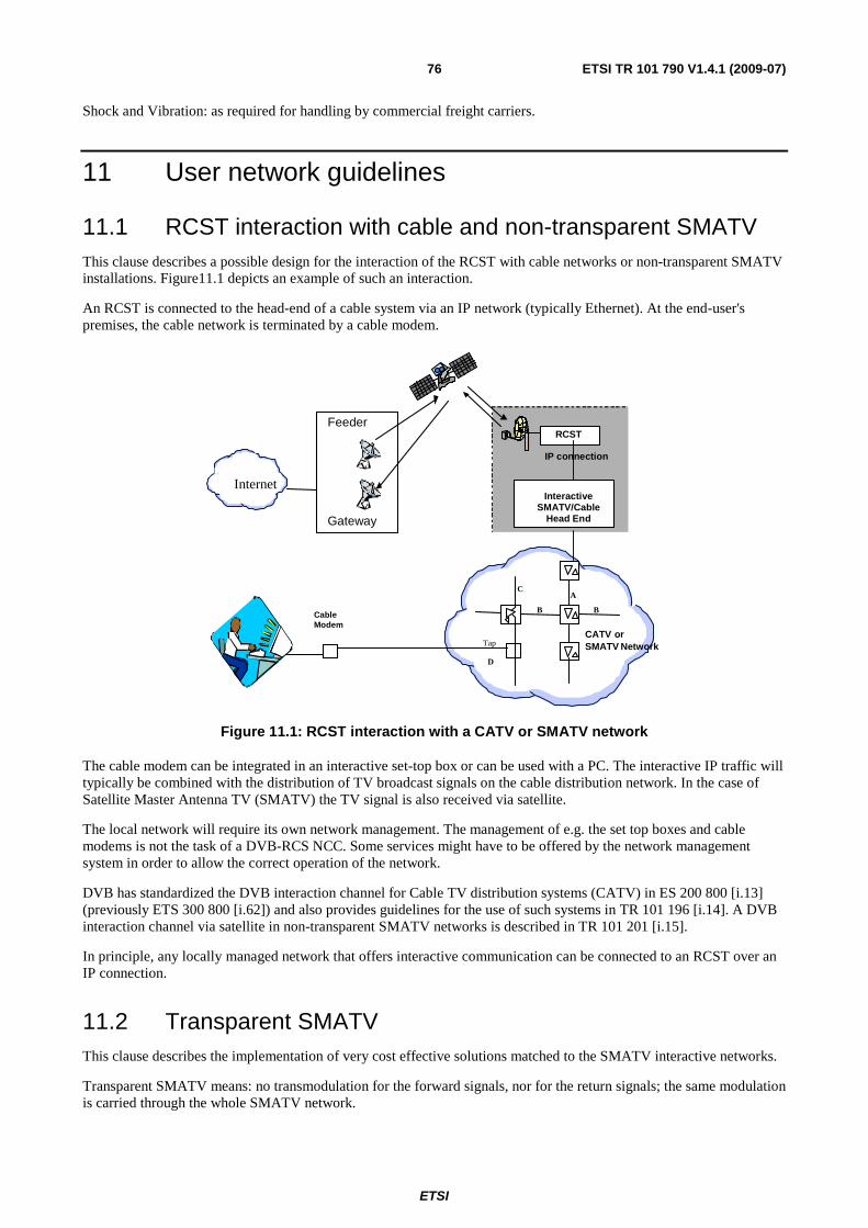
ETSI
ETSI TR 101 790 V1.4.1 (2009-07) 76
Shock and Vibration: as required for handling by commercial freight carriers.
11 User network guidelines
11.1 RCST interaction with cable and non-transparent SMATV This clause describes a possible design for the interaction of the RCST with cable networks or non-transparent SMATV installations. Figure11.1 depicts an example of such an interaction.
An RCST is connected to the head-end of a cable system via an IP network (typically Ethernet). At the end-user's premises, the cable network is terminated by a cable modem.
IP connection
InteractiveSMATV/Cable
Head End
RCST
A
B
C
B
Tap
CableModem
D
Internet
Gateway
Feeder
CATV orSMATV Network
Figure 11.1: RCST interaction with a CATV or SMATV network
The cable modem can be integrated in an interactive set-top box or can be used with a PC. The interactive IP traffic will typically be combined with the distribution of TV broadcast signals on the cable distribution network. In the case of Satellite Master Antenna TV (SMATV) the TV signal is also received via satellite.
The local network will require its own network management. The management of e.g. the set top boxes and cable modems is not the task of a DVB-RCS NCC. Some services might have to be offered by the network management system in order to allow the correct operation of the network.
DVB has standardized the DVB interaction channel for Cable TV distribution systems (CATV) in ES 200 800 [i.13] (previously ETS 300 800 [i.62]) and also provides guidelines for the use of such systems in TR 101 196 [i.14]. A DVB interaction channel via satellite in non-transparent SMATV networks is described in TR 101 201 [i.15].
In principle, any locally managed network that offers interactive communication can be connected to an RCST over an IP connection.
11.2 Transparent SMATV This clause describes the implementation of very cost effective solutions matched to the SMATV interactive networks.
Transparent SMATV means: no transmodulation for the forward signals, nor for the return signals; the same modulation is carried through the whole SMATV network.
ETSI
ETSI TR 101 790 V1.4.1 (2009-07) 77
Transparent SMATV means also: compliance of frequencies, bandwidths and levels with the SMATV European standard EN 50083 [i.11] and SMATV control channel specifications.
This concept of transparency allows the use of the same models of IDU in collective installations as in individual installations.
The SMATV transparency is already achieved for the forward signals in existing SMATV-IF installations; indeed, in such installations, the same satellite receivers can be used as in individual satellite reception. So, the solutions described in this clause are only some extensions of the SMATV-IF existing solutions.
The ODU used for SMATV-IF installations could be equipped with a 4 output LNB powered by a head-end component.
There are two ways to distribute the satellite channels in SMATV-IF installations:
• The first way is to use passive components (splitter, tap-off) in the common parts of the network. Those components are connected between themselves with only one cable. In order to maximize the number of attractive channels, nearly all of those installations are equipped with IF/IF channels reorganizers at the head-end.
• The second way is to use multiswitches in the common parts of the network. Those multiswitches are connected between themselves with five cables (nine in some cases). One of those cables carries the terrestrial channels (with or without return path implementation) and the others, connected to a four output LNB (two in case of nine cables) carry the satellite channels. Each end-user is connected to a multiswitch with only one cable.
It is foreseen that a CATV return channel network and a DVB-RCS return channel scheme will not coexist on the same SMATV installation (same cables). They can coexist with one more cable in the SMATV installation.
11.2.1 Interactive "one cable" SMATV-IF installation
This type of installation is shown schematically in figure 11.2. Most of those installations are already installed with passive components (splitter and tap-off) working from 5 MHz to 2 150 MHz.
To up-grade such an installation for satellite interactivity, it suffices to replace the existing dish by an ODU and to add a component connected to the head-end for filtering the signals and powering the ODU.
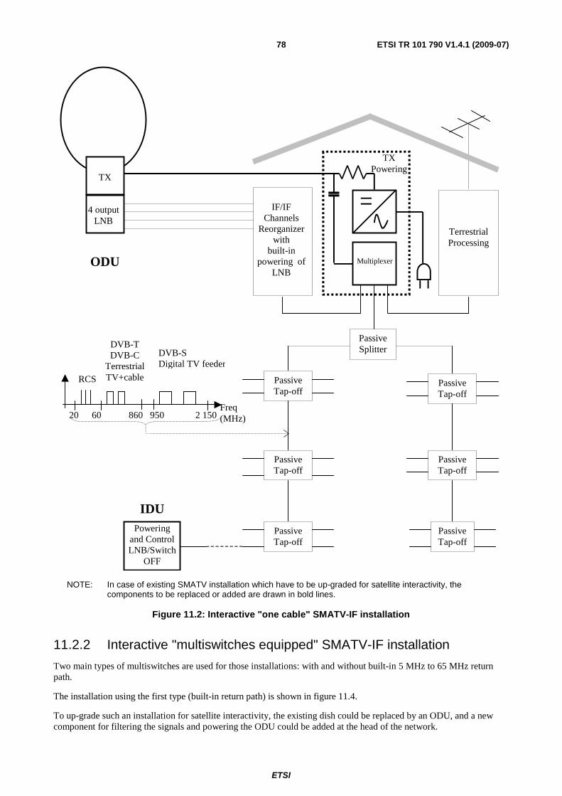
ETSI
ETSI TR 101 790 V1.4.1 (2009-07) 78
Multiplexer
IF/IF Channels
Reorganizer with
built-in powering of
LNB
Terrestrial Processing
TX Powering
TX
4 output LNB
ODU
Passive Splitter
Passive Tap-off
Passive Tap-off
Passive Tap-off
Passive Tap-off
Passive Tap-off
Passive Tap-off
IDU Powering
and Control LNB/Switch
OFF
20 60
RCS
860 950
DVB-T DVB-C
Terrestrial TV+cable
2 150 Freq (MHz)
DVB-S Digital TV feeder
NOTE: In case of existing SMATV installation which have to be up-graded for satellite interactivity, the components to be replaced or added are drawn in bold lines.
Figure 11.2: Interactive "one cable" SMATV-IF installation
11.2.2 Interactive "multiswitches equipped" SMATV-IF installation
Two main types of multiswitches are used for those installations: with and without built-in 5 MHz to 65 MHz return path.
The installation using the first type (built-in return path) is shown in figure 11.4.
To up-grade such an installation for satellite interactivity, the existing dish could be replaced by an ODU, and a new component for filtering the signals and powering the ODU could be added at the head of the network.
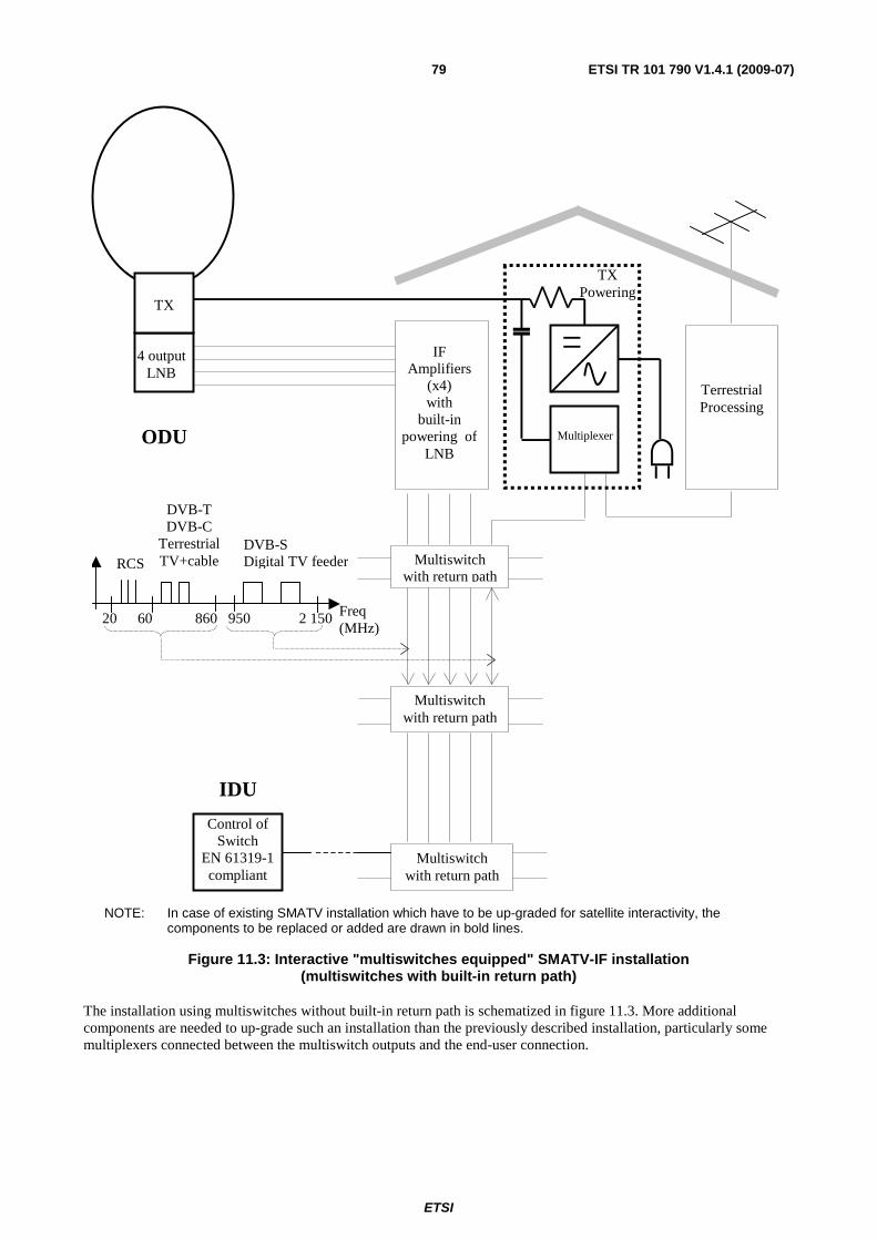
ETSI
ETSI TR 101 790 V1.4.1 (2009-07) 79
Multiplexer
IF Amplifiers
(x4) with
built-in powering of
LNB
Terrestrial Processing
TX Powering
TX
4 output LNB
ODU
Multiswitch with return path
Multiswitch with return path
Multiswitch with return path
IDU
Control of Switch
EN 61319-1 compliant
20 60
RCS
860 950
DVB-T DVB-C
Terrestrial TV+cable
2 150 Freq (MHz)
DVB-S Digital TV feeder
NOTE: In case of existing SMATV installation which have to be up-graded for satellite interactivity, the components to be replaced or added are drawn in bold lines.
Figure 11.3: Interactive "multiswitches equipped" SMATV-IF installation
(multiswitches with built-in return path)
The installation using multiswitches without built-in return path is schematized in figure 11.3. More additional components are needed to up-grade such an installation than the previously described installation, particularly some multiplexers connected between the multiswitch outputs and the end-user connection.
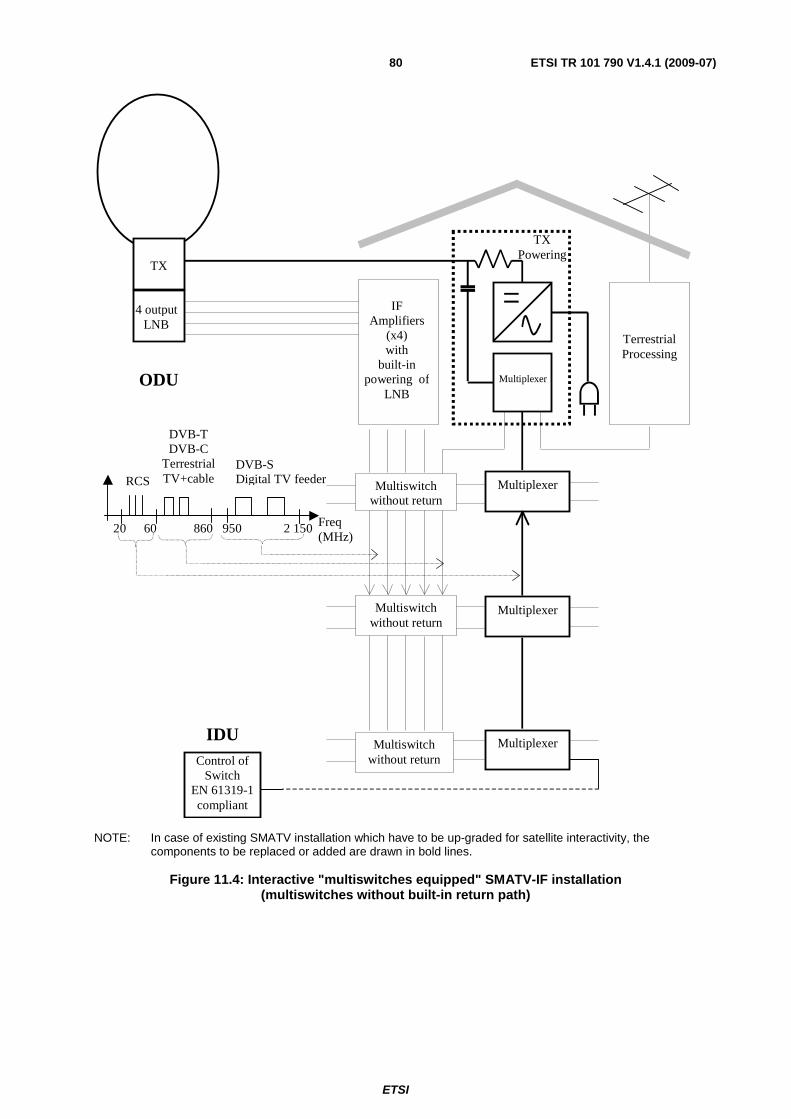
ETSI
ETSI TR 101 790 V1.4.1 (2009-07) 80
Multiplexer
IF Amplifiers
(x4) with
built-in powering of
LNB
Terrestrial Processing
TX Powering
TX
4 output LNB
ODU
Multiswitch without return
Multiswitch without return
Multiswitch without return
IDU
Multiplexer
Multiplexer
Multiplexer Control of
Switch EN 61319-1 compliant
20 60
RCS
860 950
DVB-T DVB-C
Terrestrial TV+cable
2 150 Freq (MHz)
DVB-S Digital TV feeder
NOTE: In case of existing SMATV installation which have to be up-graded for satellite interactivity, the components to be replaced or added are drawn in bold lines.
Figure 11.4: Interactive "multiswitches equipped" SMATV-IF installation
(multiswitches without built-in return path)
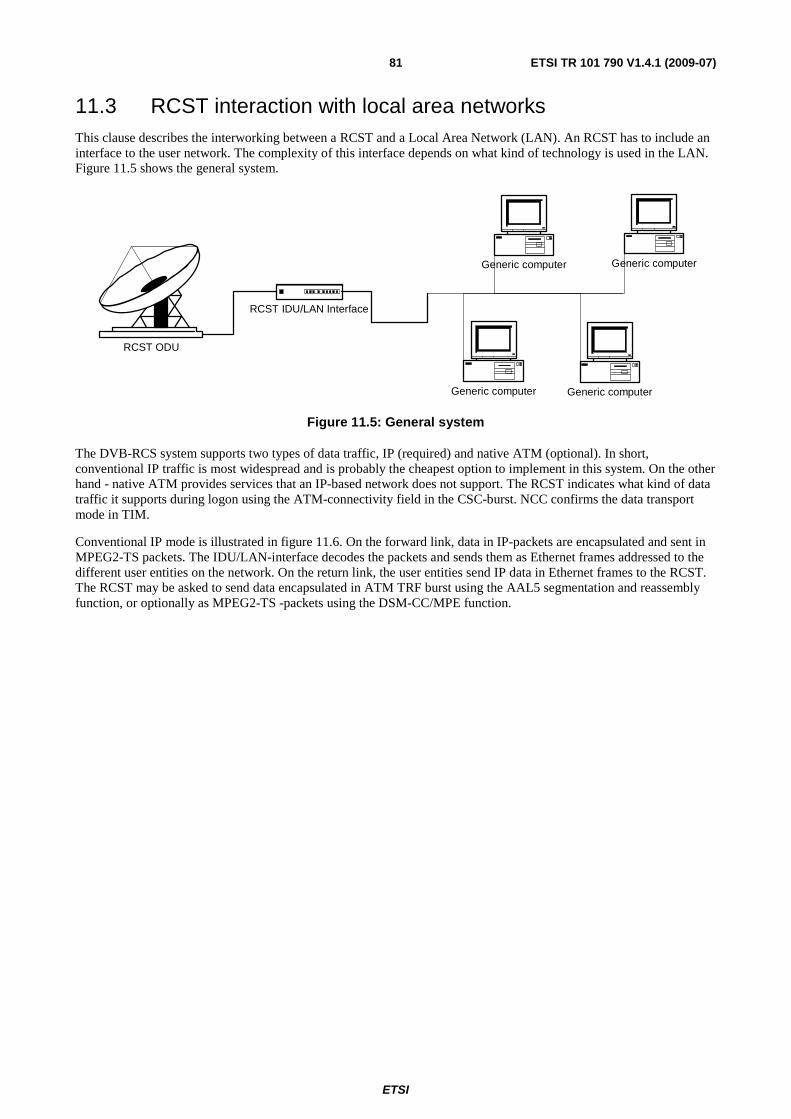
ETSI
ETSI TR 101 790 V1.4.1 (2009-07) 81
11.3 RCST interaction with local area networks This clause describes the interworking between a RCST and a Local Area Network (LAN). An RCST has to include an interface to the user network. The complexity of this interface depends on what kind of technology is used in the LAN. Figure 11.5 shows the general system.
RCST ODU
RCST IDU/LAN Interface
Generic computer Generic computer
Generic computer Generic computer
Figure 11.5: General system
The DVB-RCS system supports two types of data traffic, IP (required) and native ATM (optional). In short, conventional IP traffic is most widespread and is probably the cheapest option to implement in this system. On the other hand - native ATM provides services that an IP-based network does not support. The RCST indicates what kind of data traffic it supports during logon using the ATM-connectivity field in the CSC-burst. NCC confirms the data transport mode in TIM.
Conventional IP mode is illustrated in figure 11.6. On the forward link, data in IP-packets are encapsulated and sent in MPEG2-TS packets. The IDU/LAN-interface decodes the packets and sends them as Ethernet frames addressed to the different user entities on the network. On the return link, the user entities send IP data in Ethernet frames to the RCST. The RCST may be asked to send data encapsulated in ATM TRF burst using the AAL5 segmentation and reassembly function, or optionally as MPEG2-TS -packets using the DSM-CC/MPE function.
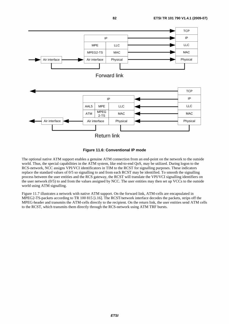
ETSI
ETSI TR 101 790 V1.4.1 (2009-07) 82
Forward link
Air interface
IP
MPE
MPEG2-TS
PhysicalAir interface
LLC
MAC
Physical
LLC
MAC
IP
TCP
Return link
Air interface Physical
LLC
MAC
IP
TCP
IP
PhysicalAir interface
LLC
MAC
AAL5
ATM
MPE
MPEG2-TS
Figure 11.6: Conventional IP mode
The optional native ATM support enables a genuine ATM connection from an end-point on the network to the outside world. Thus, the special capabilities in the ATM system, like end-to-end QoS, may be utilized. During logon to the RCS-network, NCC assigns VPI/VCI identificators in TIM to the RCST for signalling purposes. These indicators replace the standard values of 0/5 so signalling to and from each RCST may be identified. To smooth the signalling process between the user entities and the RCS gateway, the RCST will translate the VPI/VCI signalling identifiers on the user network (0/5) to and from the values assigned by NCC. The user entities may then set up VCCs to the outside world using ATM signalling.
Figure 11.7 illustrates a network with native ATM support. On the forward link, ATM-cells are encapsulated in MPEG2-TS-packets according to TR 100 815 [i.16]. The RCST/network interface decodes the packets, strips off the MPEG-header and transmits the ATM-cells directly to the recipient. On the return link, the user entities send ATM cells to the RCST, which transmits them directly through the RCS-network using ATM TRF bursts.
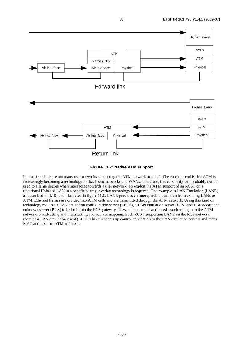
ETSI
ETSI TR 101 790 V1.4.1 (2009-07) 83
Air interface Physical
AALs
ATM
Higher layers
PhysicalAir interface
MPEG2_TS
Forward link
ATM
Air interface PhysicalAir interface Physical
AALs
ATM
Higher layers
ATM
Return link
Figure 11.7: Native ATM support
In practice, there are not many user networks supporting the ATM network protocol. The current trend is that ATM is increasingly becoming a technology for backbone networks and WANs. Therefore, this capability will probably not be used to a large degree when interfacing towards a user network. To exploit the ATM support of an RCST on a traditional IP-based LAN in a beneficial way, overlay technology is required. One example is LAN Emulation (LANE) as described in [i.10] and illustrated in figure 11.8. LANE provides an interoperable transition from existing LANs to ATM. Ethernet frames are divided into ATM cells and are transmitted through the ATM network. Using this kind of technology requires a LAN emulation configuration server (LECS), a LAN emulation server (LES) and a Broadcast and unknown server (BUS) to be built into the RCS-gateway. These components handle tasks such as logon to the ATM network, broadcasting and multicasting and address mapping. Each RCST supporting LANE on the RCS-network requires a LAN emulation client (LEC). This client sets up control connection to the LAN emulation servers and maps MAC addresses to ATM addresses.
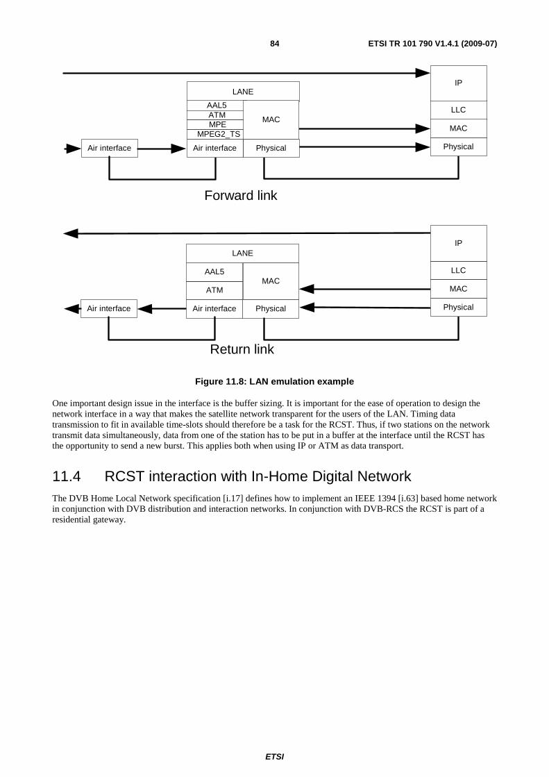
ETSI
ETSI TR 101 790 V1.4.1 (2009-07) 84
Air interface Physical
LLC
MAC
IPLANE
PhysicalAir interface
ATMAAL5
MPEMPEG2_TS
Forward link
MAC
Return link
Air interface
LANE
PhysicalAir interface Physical
LLC
MAC
IP
ATM
AAL5MAC
Figure 11.8: LAN emulation example
One important design issue in the interface is the buffer sizing. It is important for the ease of operation to design the network interface in a way that makes the satellite network transparent for the users of the LAN. Timing data transmission to fit in available time-slots should therefore be a task for the RCST. Thus, if two stations on the network transmit data simultaneously, data from one of the station has to be put in a buffer at the interface until the RCST has the opportunity to send a new burst. This applies both when using IP or ATM as data transport.
11.4 RCST interaction with In-Home Digital Network The DVB Home Local Network specification [i.17] defines how to implement an IEEE 1394 [i.63] based home network in conjunction with DVB distribution and interaction networks. In conjunction with DVB-RCS the RCST is part of a residential gateway.
ETSI
ETSI TR 101 790 V1.4.1 (2009-07) 85
Annex A: Examples of incorporation of satellite based return channel into a digital television platform This annex describes one method of integrating the DVB-RCS return channel into an already DVB compliant digital television platform. Figure A.1 shows such a system. Data connections are marked with solid lines, and control (Ethernet) connections are dashed lines.
Feeder/Gateway: As far as the existing platform is concerned, this will be another TV (MPEG-2) channel. The feed to the multiplexers will be e.g. a PC connected to the Internet through a number of high-speed connections. The maximum number of requests to an external network (for example, Internet) is assumed to be implementation dependent. Capacity assignments for the individual RCST will have to be taken into account when IP-packets are packed inside the MPEG-2 transport stream. In addition, the total forward bit rate for this unit will be controlled from the NCC and in the last instance from the SYSTEM CONTROLLER. The total forward bit rate should be specified as a constant or minimum amount to allow for a guaranteed bit rate for an individual RCST.
Receiver/Demodulator: Generally, the same antenna can be used in both directions NCC. Controls the timing, synchronization and other control parameters for the whole return channel system. This is again assumed to be under supervisory control from the SYSTEM CONTROLLER, which has direct control over the bit rate for all feeders. The NCC and SYSTEM CONTROLLER may be integrated when and if the system is realized, and this is partly done by assuming the Gateway/Feeder unit to be controlled by the NCC via the SYSTEM CONTROLLER. The NCC controls the generation of SI data through the connection to the SI generator.
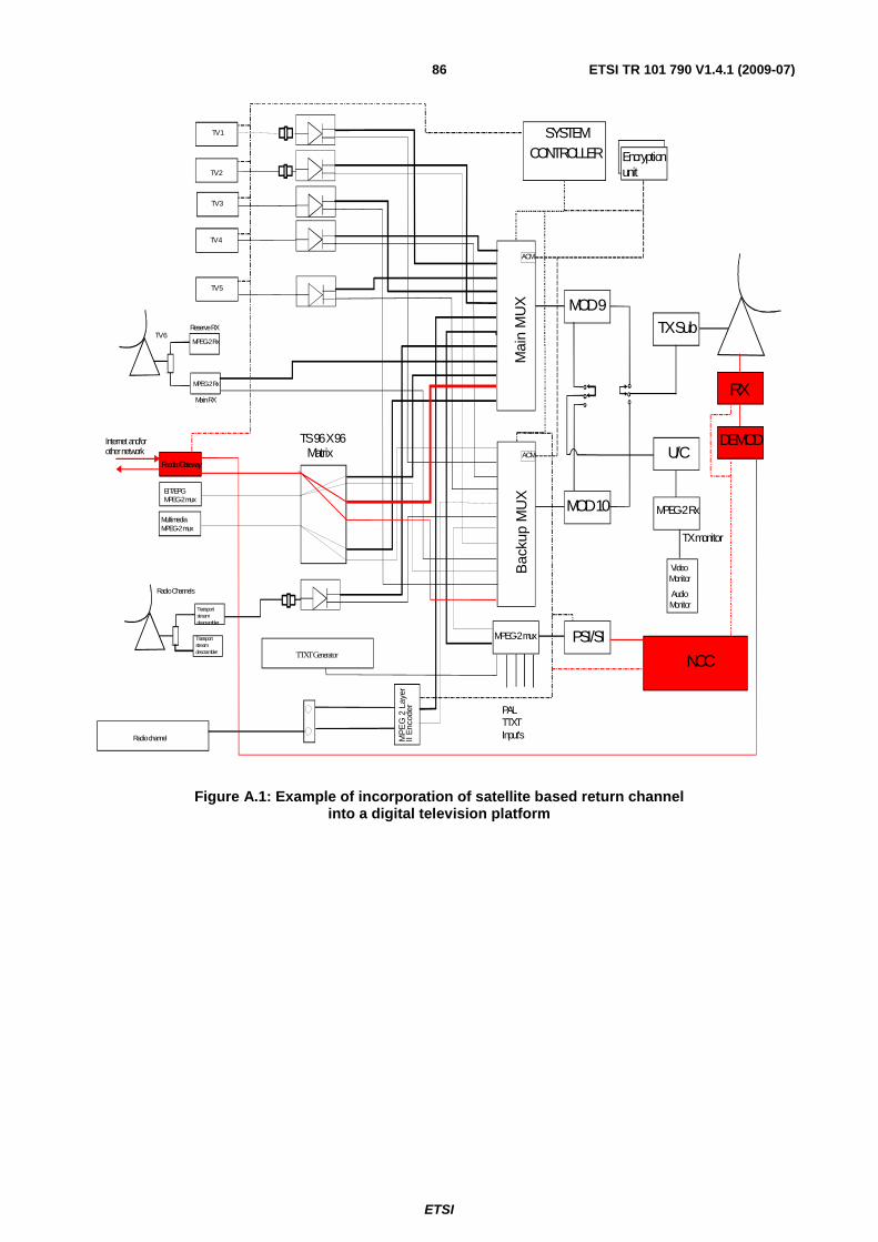
ETSI
ETSI TR 101 790 V1.4.1 (2009-07) 86
MPEG-2 mux PSI/SI
PAL TTXTInput's
Bac
kup
MU
XMOD 10
U/C
MPEG-2 Rx
TX monitor
TX Sub
SYSTEMCONTROLLER
Multimedia MPEG-2 mux
Mai
n M
UX MOD 9
MPEG-2 Rx
MPEG-2 Rx
Main RX
Reserve RX
AudioMonitor
VideoMonitor
Transportstreamdescrambler
Radio Channels
ACM
ACM
Encryptionunit
MP
EG
2 L
ayer
II E
ncod
er
Radio channel
TS 96 X 96 Matrix
TV 2
TV 1
EIT/EPGMPEG-2 mux
TTXT Generator
TV 3
TV 4
RX
DEMOD
NCC
Feeder/Gateway
Internet and/orother network
TV 5
TV 6
Transportstreamdescrambler
Figure A.1: Example of incorporation of satellite based return channel into a digital television platform
ETSI
ETSI TR 101 790 V1.4.1 (2009-07) 87
Annex B: RCST IDU/ODU IFL protocol description This is a description of a protocol between the IDU and ODU where the IDU acts as a Master and the ODU acts as a Slave. The protocol is based on an extension of the Eutelsat DiSEqC™ bus specification Version 4.2 [i.18].
The control and management of a DiSEqC™ ODU is not completely defined by this specification and system dependent issues has to be expected. There are as well optional protocol elements. It has to be expected that an IDU will need some special adaptation to partly and fully exploit a specific type of DiSEqC™ ODU.
B.1 Command and request processing Only one command or status request can be processed at a time. Once the IDU has issued a command or status request to the ODU, a new command cannot be issued until the IDU has received a valid response (ACK or NACK) or the command has timed out. In the case of either a NACK or time-out, the IDU may issue a given command up to three times before declaring a fault on the interface.
B.2 Alarms When a hardware alarm occurs within the ODU, the ODU should:
1) disable the SSPA to inhibit transmission by removing power to the Tx circuit;
2) disable the frequency reference signal provided to the IDU (if implemented);
3) buffer the fault indication until read or cleared by the IDU.
After detecting the ODU fault (via loss of reference, hub report of abnormal logoff or time-out of command request), the IDU should send a status request message to the ODU to identify the type of alarm.
B.3 Dynamic behaviour Unless otherwise specified in the subsequent clauses, the ODU should respond to a command or request received from the IDU within the allowable timeout period (TOODU) of 150 ms. In general, to force the ODU to respond immediately to a command/request from the IDU, the DiSEqC™ command 0x01 may be sent after any power-on or (re-) initialization procedure.
NOTE: DiSEqC™ devices will by default apply a random response time between 15 ms and 115 ms, and even 135 ms in case of need for collision avoidance.
The TOODU may be disabled during installation.
B.4 Error recovery mechanism When the IDU does not receive its expected answer (no answer or NACK), it may re-send the message twice, after which an alarm should be raised. From the ODUs point of view, there will be no limitations on the number of times that the IDU can attempt to send a message. If the ODU keeps receiving messages in error, it will continually respond with the error code. If there is an invalid password, and the ODU requires command authorization, it will "lock-up" after the sixth attempt (see clause B.5.4).
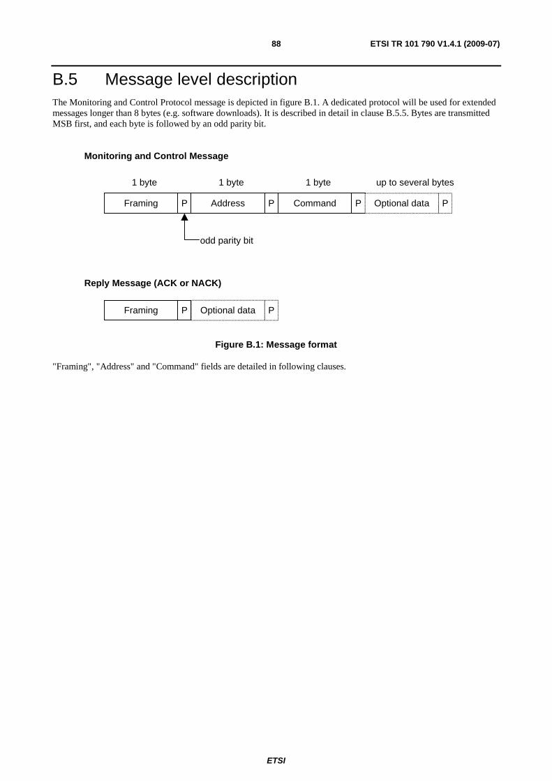
ETSI
ETSI TR 101 790 V1.4.1 (2009-07) 88
B.5 Message level description The Monitoring and Control Protocol message is depicted in figure B.1. A dedicated protocol will be used for extended messages longer than 8 bytes (e.g. software downloads). It is described in detail in clause B.5.5. Bytes are transmitted MSB first, and each byte is followed by an odd parity bit.
Framing P Address P Command P Optional data P
1 byte 1 byte 1 byte
odd parity bit
up to several bytes
Framing P Optional data P
Monitoring and Control Message
Reply Message (ACK or NACK)
Figure B.1: Message format
"Framing", "Address" and "Command" fields are detailed in following clauses.
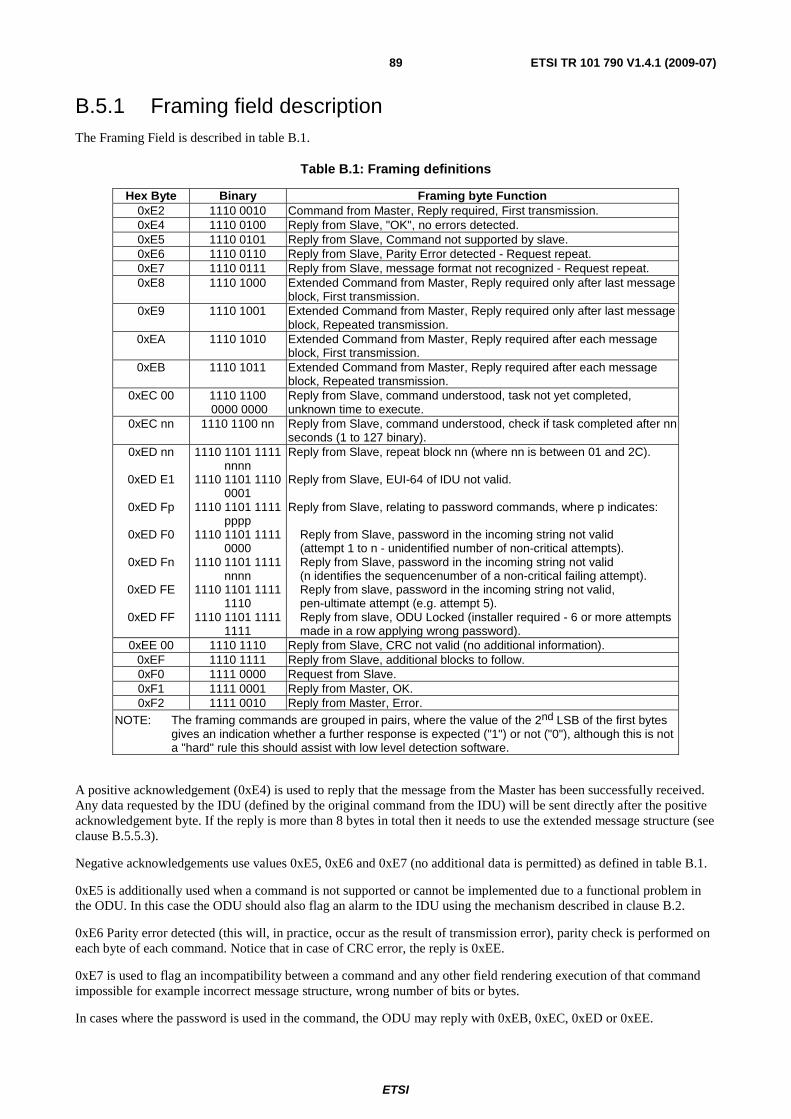
ETSI
ETSI TR 101 790 V1.4.1 (2009-07) 89
B.5.1 Framing field description The Framing Field is described in table B.1.
Table B.1: Framing definitions
Hex Byte Binary Framing byte Function 0xE2 1110 0010 Command from Master, Reply required, First transmission. 0xE4 1110 0100 Reply from Slave, "OK", no errors detected. 0xE5 1110 0101 Reply from Slave, Command not supported by slave. 0xE6 1110 0110 Reply from Slave, Parity Error detected - Request repeat. 0xE7 1110 0111 Reply from Slave, message format not recognized - Request repeat. 0xE8 1110 1000 Extended Command from Master, Reply required only after last message
block, First transmission. 0xE9 1110 1001 Extended Command from Master, Reply required only after last message
block, Repeated transmission. 0xEA 1110 1010 Extended Command from Master, Reply required after each message
block, First transmission. 0xEB 1110 1011 Extended Command from Master, Reply required after each message
block, Repeated transmission. 0xEC 00 1110 1100
0000 0000 Reply from Slave, command understood, task not yet completed, unknown time to execute.
0xEC nn 1110 1100 nn Reply from Slave, command understood, check if task completed after nn seconds (1 to 127 binary).
0xED nn
0xED E1
0xED Fp
0xED F0
0xED Fn
0xED FE
0xED FF
1110 1101 1111 nnnn
1110 1101 1110 0001
1110 1101 1111 pppp
1110 1101 1111 0000
1110 1101 1111 nnnn
1110 1101 1111 1110
1110 1101 1111 1111
Reply from Slave, repeat block nn (where nn is between 01 and 2C). Reply from Slave, EUI-64 of IDU not valid. Reply from Slave, relating to password commands, where p indicates:
Reply from Slave, password in the incoming string not valid (attempt 1 to n - unidentified number of non-critical attempts). Reply from Slave, password in the incoming string not valid (n identifies the sequencenumber of a non-critical failing attempt). Reply from slave, password in the incoming string not valid, pen-ultimate attempt (e.g. attempt 5). Reply from slave, ODU Locked (installer required - 6 or more attempts made in a row applying wrong password).
0xEE 00 1110 1110 Reply from Slave, CRC not valid (no additional information). 0xEF 1110 1111 Reply from Slave, additional blocks to follow. 0xF0 1111 0000 Request from Slave. 0xF1 1111 0001 Reply from Master, OK. 0xF2 1111 0010 Reply from Master, Error.
NOTE: The framing commands are grouped in pairs, where the value of the 2nd LSB of the first bytes gives an indication whether a further response is expected ("1") or not ("0"), although this is not a "hard" rule this should assist with low level detection software.
A positive acknowledgement (0xE4) is used to reply that the message from the Master has been successfully received. Any data requested by the IDU (defined by the original command from the IDU) will be sent directly after the positive acknowledgement byte. If the reply is more than 8 bytes in total then it needs to use the extended message structure (see clause B.5.5.3).
Negative acknowledgements use values 0xE5, 0xE6 and 0xE7 (no additional data is permitted) as defined in table B.1.
0xE5 is additionally used when a command is not supported or cannot be implemented due to a functional problem in the ODU. In this case the ODU should also flag an alarm to the IDU using the mechanism described in clause B.2.
0xE6 Parity error detected (this will, in practice, occur as the result of transmission error), parity check is performed on each byte of each command. Notice that in case of CRC error, the reply is 0xEE.
0xE7 is used to flag an incompatibility between a command and any other field rendering execution of that command impossible for example incorrect message structure, wrong number of bits or bytes.
In cases where the password is used in the command, the ODU may reply with 0xEB, 0xEC, 0xED or 0xEE.
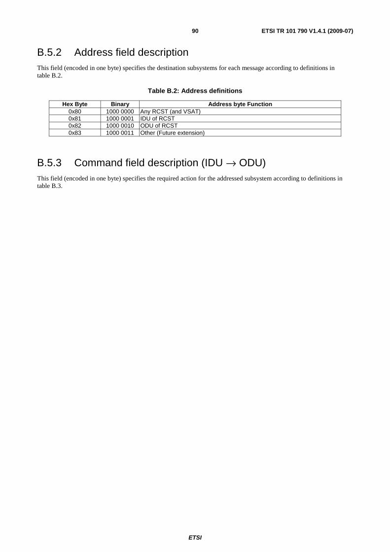
ETSI
ETSI TR 101 790 V1.4.1 (2009-07) 90
B.5.2 Address field description This field (encoded in one byte) specifies the destination subsystems for each message according to definitions in table B.2.
Table B.2: Address definitions
Hex Byte Binary Address byte Function 0x80 1000 0000 Any RCST (and VSAT) 0x81 1000 0001 IDU of RCST 0x82 1000 0010 ODU of RCST 0x83 1000 0011 Other (Future extension)
B.5.3 Command field description (IDU → ODU) This field (encoded in one byte) specifies the required action for the addressed subsystem according to definitions in table B.3.

ETSI
ETSI TR 101 790 V1.4.1 (2009-07) 91
Table B.3: Command definitions
Hex. Byte
Use password Command
Status Action
00 No Reset O Reset all the ODU functions (same as power down reset) 0A No Soft Reset O ODU Software Reset 12 No Monitoring M Request the general status of the ODU 5C No Manufacturer's ID M Request Manufacturer's Identification 5D No Product ID M Request the Product's Identification C1 No Download start O Allow the ODU to enter into download mode C2 No Download data O Download software data C3 No Download abort O Abort the download process C4 No Download valid O Grab the "new" software into a non volatile memory C5 No Download toggle O Toggle between current software version and previous one C6 Optional SSPA ON M Enable the ODU amplification output C7 No SSPA OFF M Disable the ODU amplification output C8 Optional Set power level O Set SSPA power level C9 No Mod ON O Normal operation CA Optional Mod OFF O Modulation Off, transmit Continuous Wave (CW) CB Yes Change password O Enable the ODU password modification CC Yes Validate password O Activate the new password CD Yes Reset ODU locked O Reset the "Faulty password counter" and back to default password CE No Transmitter Disable M ODU to power down transmitter
CF Optional Transmitter Enable
M ODU to power up transmitter (SSPA remains off)
D0 No Get calibration table O Get the ODU calibration data for temperature and frequency variations
D1 No Get Temperature O Report temperature of the ODU
D2 No Get power output value
O Get the ODU measured power output
D3 No Get Location O Get the ODU geographical location (latitude, longitude, altitude) D4 Optional Set Location O Set the ODU location (when stored in ODU) D5 No Serial Number M Request the ODU serial number D6 No Firmware version M Request the ODU firmware version D7 No Set Rx_Freq. O Set Rx Carrier Frequency to ODU D8 No Set Beacon_Freq O Set Beacon Frequency to ODU D9 No Set Tx_Freq O Set Tx Carrier Frequency to ODU DA No Set Satellite_ID O Set Satellite ID to ODU DB No Track OFF O Report Tracking status(OFF) to IDU DC No Track ON O Report Tracking status(ON) to IDU
DD to DE - - - Reserved for future standard commands
DF - - - Reserved for ODU manufacturer dependent commands NOTE: M = Mandatory, O = Optional (in case function is not supported).
B.5.4 Password (optional) A password may be required by the ODU for some commands in order to avoid inadvertent transmission or unapproved use of the ODU. The password will consist of 4 bytes and may be required together with the designated commands shown in table B.3. In these cases the password will immediately follow the relevant command byte, if there is any associated data used by these commands, it will be sent in a following block (see clause B.5.5).
The ODU will refuse commands if the password does not correspond to its current valid password. After 5 consecutive erroneous passwords, the ODU will warn that only 1 try remains. After the 6th faulty password, ODU might refuse all commands except the status request, transmitter disable command and the download commands. These last commands allow an expert to reset the "Faulty password counter" and reset to the default password. The default password is system dependent.
When the ODU becomes locked due to 6 consecutive incorrect passwords, the SSPA will be disabled and the transmitter powered down.
In the following clauses, the password is noted "PWD" in the commands description.
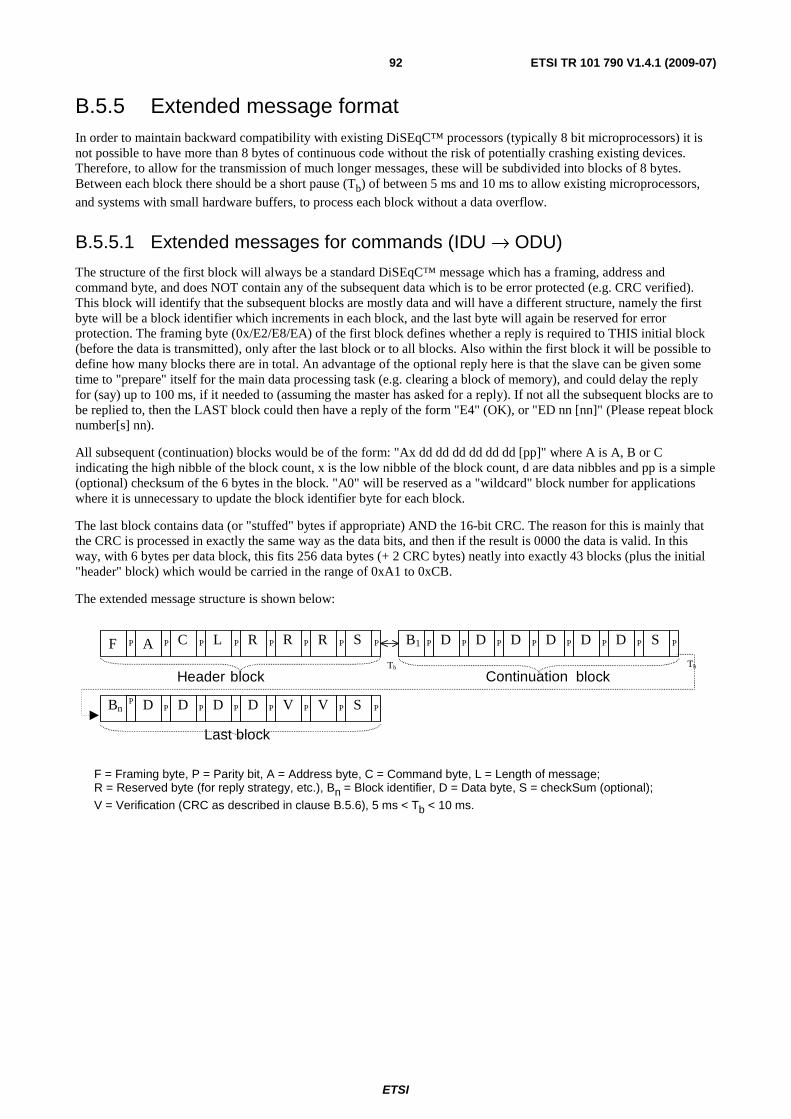
ETSI
ETSI TR 101 790 V1.4.1 (2009-07) 92
B.5.5 Extended message format In order to maintain backward compatibility with existing DiSEqC™ processors (typically 8 bit microprocessors) it is not possible to have more than 8 bytes of continuous code without the risk of potentially crashing existing devices. Therefore, to allow for the transmission of much longer messages, these will be subdivided into blocks of 8 bytes. Between each block there should be a short pause (Tb) of between 5 ms and 10 ms to allow existing microprocessors, and systems with small hardware buffers, to process each block without a data overflow.
B.5.5.1 Extended messages for commands (IDU → ODU)
The structure of the first block will always be a standard DiSEqC™ message which has a framing, address and command byte, and does NOT contain any of the subsequent data which is to be error protected (e.g. CRC verified). This block will identify that the subsequent blocks are mostly data and will have a different structure, namely the first byte will be a block identifier which increments in each block, and the last byte will again be reserved for error protection. The framing byte (0x/E2/E8/EA) of the first block defines whether a reply is required to THIS initial block (before the data is transmitted), only after the last block or to all blocks. Also within the first block it will be possible to define how many blocks there are in total. An advantage of the optional reply here is that the slave can be given some time to "prepare" itself for the main data processing task (e.g. clearing a block of memory), and could delay the reply for (say) up to 100 ms, if it needed to (assuming the master has asked for a reply). If not all the subsequent blocks are to be replied to, then the LAST block could then have a reply of the form "E4" (OK), or "ED nn [nn]" (Please repeat block number[s] nn).
All subsequent (continuation) blocks would be of the form: "Ax dd dd dd dd dd dd [pp]" where A is A, B or C indicating the high nibble of the block count, x is the low nibble of the block count, d are data nibbles and pp is a simple (optional) checksum of the 6 bytes in the block. "A0" will be reserved as a "wildcard" block number for applications where it is unnecessary to update the block identifier byte for each block.
The last block contains data (or "stuffed" bytes if appropriate) AND the 16-bit CRC. The reason for this is mainly that the CRC is processed in exactly the same way as the data bits, and then if the result is 0000 the data is valid. In this way, with 6 bytes per data block, this fits 256 data bytes (+ 2 CRC bytes) neatly into exactly 43 blocks (plus the initial "header" block) which would be carried in the range of 0xA1 to 0xCB.
The extended message structure is shown below:
TbTb
F A C L R R R SP P P P P P P P B1 D D D D D D SP P P P P P P P
Bn D D D D V V SPP P P P P P P
Header block Continuation block
Last block
F = Framing byte, P = Parity bit, A = Address byte, C = Command byte, L = Length of message; R = Reserved byte (for reply strategy, etc.), Bn = Block identifier, D = Data byte, S = checkSum (optional);
V = Verification (CRC as described in clause B.5.6), 5 ms < Tb < 10 ms.
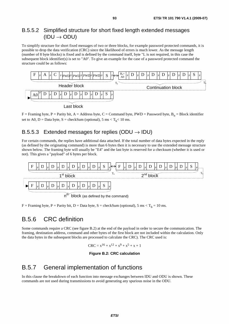
ETSI
ETSI TR 101 790 V1.4.1 (2009-07) 93
B.5.5.2 Simplified structure for short fixed length extended messages (IDU → ODU)
To simplify structure for short fixed messages of two or three blocks, for example password protected commands, it is possible to drop the data verification (CRC) since the likelihood of errors is much lower. As the message length (number of 8 byte blocks) is fixed and is defined by the command itself, byte "L is not required, in this case the subsequent block identifier(s) is set to "A0". To give an example for the case of a password protected command the structure could be as follows:
TbTb
F A C PWD SP P P P P P P PBn=A0
D D D D D D SP P P P P P P P
A0 D D D D D D SPP P P P P P P
Header block Continuation block
Last block
PWDPWDPWD
F = Framing byte, P = Parity bit, A = Address byte, C = Command byte, PWD = Password byte, Bn = Block identifier
set to A0, D = Data byte, S = checkSum (optional), 5 ms < Tb< 10 ms.
B.5.5.3 Extended messages for replies (ODU → IDU)
For certain commands, the replies have additional data attached. If the total number of data bytes expected in the reply (as defined by the originating command) is more than 6 bytes then it is necessary to use the extended message structure shown below. The framing byte will usually be "E4" and the last byte is reserved for a checksum (whether it is used or not). This gives a "payload" of 6 bytes per block.
TbTb
F DP P P P P P P P
1st block 2nd block
nth block (as defined by the command)
D D D D D S F DP P P P P P P PD D D D D S
F DP P P P P P P PD D D D D S
F = Framing byte, P = Parity bit, D = Data byte, S = checkSum (optional), 5 ms < Tb = 10 ms.
B.5.6 CRC definition Some commands require a CRC (see figure B.2) at the end of the payload in order to secure the communication. The framing, destination address, command and other bytes of the first block are not included within the calculation. Only the data bytes in the subsequent blocks are processed to calculate the CRC). The CRC used is:
CRC = x16 + x12 + x9 + x5 + x + 1
Figure B.2: CRC calculation
B.5.7 General implementation of functions In this clause the breakdown of each function into message exchanges between IDU and ODU is shown. These commands are not used during transmissions to avoid generating any spurious noise in the ODU.
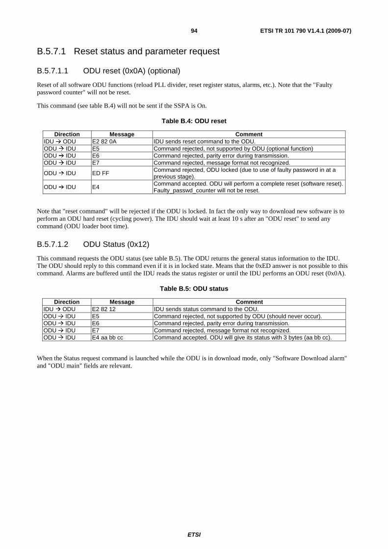
ETSI
ETSI TR 101 790 V1.4.1 (2009-07) 94
B.5.7.1 Reset status and parameter request
B.5.7.1.1 ODU reset (0x0A) (optional)
Reset of all software ODU functions (reload PLL divider, reset register status, alarms, etc.). Note that the "Faulty password counter" will not be reset.
This command (see table B.4) will not be sent if the SSPA is On.
Table B.4: ODU reset
Direction Message Comment IDU ODU E2 82 0A IDU sends reset command to the ODU. ODU IDU E5 Command rejected, not supported by ODU (optional function) ODU IDU E6 Command rejected, parity error during transmission. ODU IDU E7 Command rejected, message format not recognized.
ODU IDU ED FF Command rejected, ODU locked (due to use of faulty password in at a previous stage).
ODU IDU E4 Command accepted. ODU will perform a complete reset (software reset). Faulty_passwd_counter will not be reset.
Note that "reset command" will be rejected if the ODU is locked. In fact the only way to download new software is to perform an ODU hard reset (cycling power). The IDU should wait at least 10 s after an "ODU reset" to send any command (ODU loader boot time).
B.5.7.1.2 ODU Status (0x12)
This command requests the ODU status (see table B.5). The ODU returns the general status information to the IDU. The ODU should reply to this command even if it is in locked state. Means that the 0xED answer is not possible to this command. Alarms are buffered until the IDU reads the status register or until the IDU performs an ODU reset (0x0A).
Table B.5: ODU status
Direction Message Comment IDU ODU E2 82 12 IDU sends status command to the ODU. ODU IDU E5 Command rejected, not supported by ODU (should never occur). ODU IDU E6 Command rejected, parity error during transmission. ODU IDU E7 Command rejected, message format not recognized. ODU IDU E4 aa bb cc Command accepted. ODU will give its status with 3 bytes (aa bb cc).
When the Status request command is launched while the ODU is in download mode, only "Software Download alarm" and "ODU main" fields are relevant.
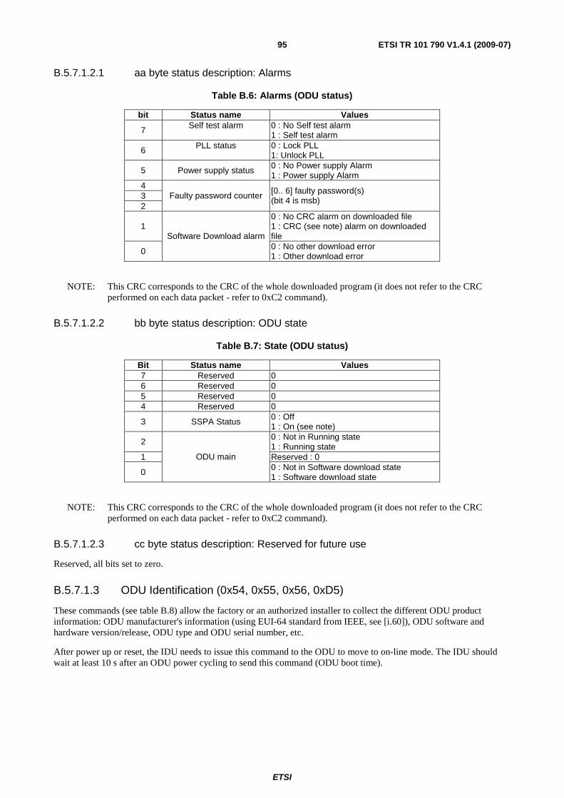
ETSI
ETSI TR 101 790 V1.4.1 (2009-07) 95
B.5.7.1.2.1 aa byte status description: Alarms
Table B.6: Alarms (ODU status)
bit Status name Values
7 Self test alarm 0 : No Self test alarm 1 : Self test alarm
6 PLL status 0 : Lock PLL 1: Unlock PLL
5 Power supply status 0 : No Power supply Alarm 1 : Power supply Alarm
4 3 2
Faulty password counter [0.. 6] faulty password(s) (bit 4 is msb)
1 0 : No CRC alarm on downloaded file 1 : CRC (see note) alarm on downloaded file
0
Software Download alarm 0 : No other download error 1 : Other download error
NOTE: This CRC corresponds to the CRC of the whole downloaded program (it does not refer to the CRC performed on each data packet - refer to 0xC2 command).
B.5.7.1.2.2 bb byte status description: ODU state
Table B.7: State (ODU status)
Bit Status name Values 7 Reserved 0 6 Reserved 0 5 Reserved 0 4 Reserved 0
3 SSPA Status 0 : Off 1 : On (see note)
2 0 : Not in Running state 1 : Running state
1 Reserved : 0
0
ODU main 0 : Not in Software download state 1 : Software download state
NOTE: This CRC corresponds to the CRC of the whole downloaded program (it does not refer to the CRC performed on each data packet - refer to 0xC2 command).
B.5.7.1.2.3 cc byte status description: Reserved for future use
Reserved, all bits set to zero.
B.5.7.1.3 ODU Identification (0x54, 0x55, 0x56, 0xD5)
These commands (see table B.8) allow the factory or an authorized installer to collect the different ODU product information: ODU manufacturer's information (using EUI-64 standard from IEEE, see [i.60]), ODU software and hardware version/release, ODU type and ODU serial number, etc.
After power up or reset, the IDU needs to issue this command to the ODU to move to on-line mode. The IDU should wait at least 10 s after an ODU power cycling to send this command (ODU boot time).
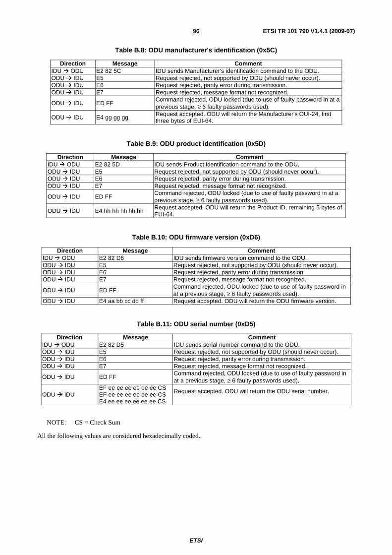
ETSI
ETSI TR 101 790 V1.4.1 (2009-07) 96
Table B.8: ODU manufacturer's identification (0x5C)
Direction Message Comment IDU ODU E2 82 5C IDU sends Manufacturer's identification command to the ODU. ODU IDU E5 Request rejected, not supported by ODU (should never occur). ODU IDU E6 Request rejected, parity error during transmission. ODU IDU E7 Request rejected, message format not recognized.
ODU IDU ED FF Command rejected, ODU locked (due to use of faulty password in at a previous stage, ≥ 6 faulty passwords used).
ODU IDU E4 gg gg gg Request accepted. ODU will return the Manufacturer's OUI-24, first three bytes of EUI-64.
Table B.9: ODU product identification (0x5D)
Direction Message Comment IDU ODU E2 82 5D IDU sends Product identification command to the ODU. ODU IDU E5 Request rejected, not supported by ODU (should never occur). ODU IDU E6 Request rejected, parity error during transmission. ODU IDU E7 Request rejected, message format not recognized.
ODU IDU ED FF Command rejected, ODU locked (due to use of faulty password in at a previous stage, ≥ 6 faulty passwords used).
ODU IDU E4 hh hh hh hh hh Request accepted. ODU will return the Product ID, remaining 5 bytes of EUI-64.
Table B.10: ODU firmware version (0xD6)
Direction Message Comment IDU ODU E2 82 D6 IDU sends firmware version command to the ODU. ODU IDU E5 Request rejected, not supported by ODU (should never occur). ODU IDU E6 Request rejected, parity error during transmission. ODU IDU E7 Request rejected, message format not recognized.
ODU IDU ED FF Command rejected, ODU locked (due to use of faulty password in at a previous stage, ≥ 6 faulty passwords used).
ODU IDU E4 aa bb cc dd ff Request accepted. ODU will return the ODU firmware version.
Table B.11: ODU serial number (0xD5)
Direction Message Comment IDU ODU E2 82 D5 IDU sends serial number command to the ODU. ODU IDU E5 Request rejected, not supported by ODU (should never occur). ODU IDU E6 Request rejected, parity error during transmission. ODU IDU E7 Request rejected, message format not recognized.
ODU IDU ED FF Command rejected, ODU locked (due to use of faulty password in at a previous stage, ≥ 6 faulty passwords used).
ODU IDU EF ee ee ee ee ee ee CS EF ee ee ee ee ee ee CS E4 ee ee ee ee ee ee CS
Request accepted. ODU will return the ODU serial number.
NOTE: CS = Check Sum
All the following values are considered hexadecimally coded.
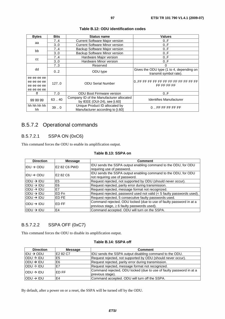
ETSI
ETSI TR 101 790 V1.4.1 (2009-07) 97
Table B.12: ODU identification codes
Bytes Bits Status name Values 7..4 Current Software Major version 0..F aa 3..0 Current Software Minor version 0..F 7..4 Backup Software Major version 0..F bb 3..0 Backup Software Minor version 0..F 7..4 Hardware Major version 0..F cc 3..0 Hardware Minor version 0..F 7..3 Reserved 0
dd 0..2 ODU type Gives the ODU type (1 to 4, depending on
transmit symbol rate). ee ee ee ee ee ee ee ee ee ee ee ee ee ee ee ee
127..0 ODU Serial Number 0..FF FF FF FF FF FF FF FF FF FF FF FF FF FF FF FF
ff 7..0 ODU Boot Firmware version 0..F
gg gg gg 63 .. 40 Company ID of the Manufacturer allocated by IEEE (OUI-24), see [i.60] Identifies Manufacturer
hh hh hh hh hh
39 .. 0 Unique Product ID allocated by Manufacturer according to [i.60]
0 .. FF FF FF FF FF
B.5.7.2 Operational commands
B.5.7.2.1 SSPA ON (0xC6)
This command forces the ODU to enable its amplification output.
Table B.13: SSPA on
Direction Message Comment
IDU ODU E2 82 C6 PWD IDU sends the SSPA output enabling command to the ODU, for ODU requiring use of password.
IDU ODU E2 82 C6 IDU sends the SSPA output enabling command to the ODU, for ODU not requiring use of password.
ODU IDU E5 Request rejected, not supported by ODU (should never occur). ODU IDU E6 Request rejected, parity error during transmission. ODU IDU E7 Request rejected, message format not recognized. ODU IDU ED Fn Request rejected, password used not valid (< 5 faulty passwords used). ODU IDU ED FE Request rejected, 5 consecutive faulty passwords used.
ODU IDU ED FF Command rejected, ODU locked (due to use of faulty password in at a previous stage, ≥ 6 faulty passwords used).
ODU IDU E4 Command accepted. ODU will turn on the SSPA.
B.5.7.2.2 SSPA OFF (0xC7)
This command forces the ODU to disable its amplification output.
Table B.14: SSPA off
Direction Message Comment IDU ODU E2 82 C7 IDU sends the SSPA output disabling command to the ODU. ODU IDU E5 Request rejected, not supported by ODU (should never occur). ODU IDU E6 Request rejected, parity error during transmission. ODU IDU E7 Request rejected, message format not recognized.
ODU IDU ED FF Command rejected, ODU locked (due to use of faulty password in at a previous stage).
ODU IDU E4 Command accepted. ODU will turn off the SSPA.
By default, after a power on or a reset, the SSPA will be turned off by the ODU.

ETSI
ETSI TR 101 790 V1.4.1 (2009-07) 98
B.5.7.2.3 Transmitter disable (0xCE)
This command forces the ODU to power down the transmitter circuitry. This command will be effectuated by the ODU also when it has locked itself due to repeated use of incorrect password.
Table B.15: Transmitter Disable
Direction Message Comment IDU ODU E2 82 CE IDU sends the transmitter disable command to the ODU. ODU IDU E5 Request rejected, not supported by ODU (should never occur). ODU IDU E6 Request rejected, parity error during transmission. ODU IDU E7 Request rejected, message format not recognized. ODU IDU E4 Command accepted. ODU will disable the transmitter.
This command is issued by the IDU whenever the RCST is put in Hold State. The transmitter should not be re-enabled by the IDU as long as the RCST is in Hold State. In case of error (including internal fault conditions such as PLL unlock and/or DC powering problem) or alarm, the ODU will automatically disable the transmitter; the ODU should be unconditionally stable.
B.5.7.2.4 Transmitter enable (0xCF)
This command allows the IDU to re-enable the transmitter, e.g. when the RCST Hold State is removed. At the completion of this command, the transmitter is again powered on, but the transmitter is still in the off state.
Table B.16: Transmitter Enable
Direction Message Comment
IDU ODU E2 82 CF PWD IDU sends the transmitter enable command to the ODU for ODUs requiring use of password.
IDU ODU E2 82 CF IDU sends the transmitter enable command to the ODU ODU for ODUs not requiring use of password.
ODU IDU E5 Request rejected, not supported by ODU (should never occur). ODU IDU E6 Request rejected, parity error during transmission. ODU IDU E7 Request rejected, message format not recognized.
ODU IDU EA Command rejected, ODU locked (due to use of faulty password in at a previous stage, ≥ 6 faulty passwords used).
ODU IDU E4 Command accepted. ODU will power on transmitter.
B.5.7.2.5 Set Power level (0xC8) (optional)
This command allows the IDU to adjust the output power level of the ODU in at least 1 dB or less steps. The command instructs the ODU by indicating how many "steps" up or down encoded by one signed data byte PWR_ADJ (±128 steps), this byte will follow in a separate block.
Table B.17: Set Power Level
Direction Message Comment
IDU ODU E2 82 C8 PWD PWR_ADJ
IDU sends the Set Power Level command to the ODU followed by the value in the PWR_ADJ byte, for ODUs requiring use of password.
IDU ODU E2 82 C8 PWR_ADJ IDU sends the Set Power Level command to the ODU followed by the value in the PWR_ADJ byte, for ODUs not requiring use of password.
ODU IDU E5 Request rejected, not supported by ODU (optional function). ODU IDU E6 Request rejected, parity error during transmission. ODU IDU E7 Request rejected, message format not recognized.
ODU IDU EA Command rejected, ODU locked (due to use of faulty password in at a previous stage, ≥ 6 faulty passwords used).
ODU IDU E4 Command accepted. ODU will change power level.
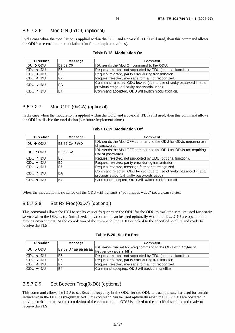
ETSI
ETSI TR 101 790 V1.4.1 (2009-07) 99
B.5.7.2.6 Mod ON (0xC9) (optional)
In the case when the modulation is applied within the ODU and a co-axial IFL is still used, then this command allows the ODU to re-enable the modulation (for future implementations).
Table B.18: Modulation On
Direction Message Comment IDU ODU E2 82 C9 IDU sends the Mod On command to the ODU. ODU IDU E5 Request rejected, not supported by ODU (optional function). ODU IDU E6 Request rejected, parity error during transmission. ODU IDU E7 Request rejected, message format not recognized.
ODU IDU EA Command rejected, ODU locked (due to use of faulty password in at a previous stage, ≥ 6 faulty passwords used).
ODU IDU E4 Command accepted. ODU will switch modulation on.
B.5.7.2.7 Mod OFF (0xCA) (optional)
In the case when the modulation is applied within the ODU and a co-axial IFL is still used, then this command allows the ODU to disable the modulation (for future implementations).
Table B.19: Modulation Off
Direction Message Comment
IDU ODU E2 82 CA PWD IDU sends the Mod OFF command to the ODU for ODUs requiring use of passwords
IDU ODU E2 82 CA IDU sends the Mod OFF command to the ODU for ODUs not requiring use of passwords.
ODU IDU E5 Request rejected, not supported by ODU (optional function). ODU IDU E6 Request rejected, parity error during transmission. ODU IDU E7 Request rejected, message format not recognized.
ODU IDU EA Command rejected, ODU locked (due to use of faulty password in at a previous stage, ≥ 6 faulty passwords used).
ODU IDU E4 Command accepted. ODU will switch modulation off.
When the modulation is switched off the ODU will transmit a "continuous wave" i.e. a clean carrier.
B.5.7.2.8 Set Rx Freq(0xD7) (optional)
This command allows the IDU to set Rx carrier frequency in the ODU for the ODU to track the satellite used for certain service when the ODU is (re-)initialized. This command can be used optionally when the IDU/ODU are operated in moving environment. At the completion of the command, the ODU is locked to the specified satellite and ready to receive the FLS.
Table B.20: Set Rx Freq
Direction Message Comment
IDU ODU E2 82 D7 aa aa aa aa IDU sends the Set Rx Freq command to the ODU with 4bytes of frequency value in MHz.
ODU IDU E5 Request rejected, not supported by ODU (optional function). ODU IDU E6 Request rejected, parity error during transmission. ODU IDU E7 Request rejected, message format not recognized. ODU IDU E4 Command accepted. ODU will track the satellite.
B.5.7.2.9 Set Beacon Freq(0xD8) (optional)
This command allows the IDU to set Beacon frequency in the ODU for the ODU to track the satellite used for certain service when the ODU is (re-)initialized. This command can be used optionally when the IDU/ODU are operated in moving environment. At the completion of the command, the ODU is locked to the specified satellite and ready to receive the FLS.

ETSI
ETSI TR 101 790 V1.4.1 (2009-07) 100
Table B.21: Set Beacon Freq
Direction Message Comment
IDU ODU E2 82 D8 aa aa aa aa IDU sends the Set Beacon Freq command to the ODU with 4bytes of frequency value in MHz.
ODU IDU E5 Request rejected, not supported by ODU (optional function). ODU IDU E6 Request rejected, parity error during transmission. ODU IDU E7 Request rejected, message format not recognized. ODU IDU E4 Command accepted. ODU will track the satellite.
B.5.7.2.10 Set Tx Freq(0xD9) (optional)
This command allows the IDU to set Tx carrier frequency in the ODU for the ODU to transmit the return link signal. This command can be used optionally when the IDU/ODU are operated in moving environment. And, Tx carrier frequency can be obtained from the FLS (e.g. superframe center frequency in SCT). At the completion of the command, the ODU is ready to send user data via return-link.
Table B.22: Set Tx Freq
Direction Message Comment
IDU ODU E2 82 D9 aa aa aa aa IDU sends the Set Tx Freq command to the ODU with 4bytes of frequency value in MHz.
ODU IDU E5 Request rejected, not supported by ODU (optional function). ODU IDU E6 Request rejected, parity error during transmission. ODU IDU E7 Request rejected, message format not recognized. ODU IDU E4 Command accepted.
B.5.7.2.11 Set Satellite_ID(0xDA) (optional)
This command allows the IDU to set Satellite ID to the ODU so that the ODU can select target satellite among the several searched satellites. This command can be used optionally when the IDU/ODU are operated in moving environment. This command may be used on the premise that ODU has all satellite information such as satellite position, channel configuration, and so on. This command has to be sent by IDU in the initial step of the ODU if mobile antenna is used.
Table B.23: Set Satellite_ID
Direction Message Comment
IDU ODU E2 82 DA aa aa aa IDU sends the Set Satellite_ID command to the ODU with 3bytes of ID value(satellite_ID : 2bytes, beam_ID : 1byte).
ODU IDU E5 Request rejected, not supported by ODU (optional function). ODU IDU E6 Request rejected, parity error during transmission. ODU IDU E7 Request rejected, message format not recognized. ODU IDU E4 Command accepted.
B.5.7.2.12 Track OFF(0xDB) (optional)
This command has to be issued by ODU whenever ODU detects missing of the satellite. This command allows the IDU to stop sending user data and start buffering. IDU can only resume sending data when it receives Track ON command from ODU.
Table B.24: Track OFF
Direction Message Comment ODU IDU F0 81 DB ODU sends the Track OFF command to indicate it"s tracking status(OFF). IDU ODU F1 Command accepted. IDU ODU F2 Request rejected, error during transmission.
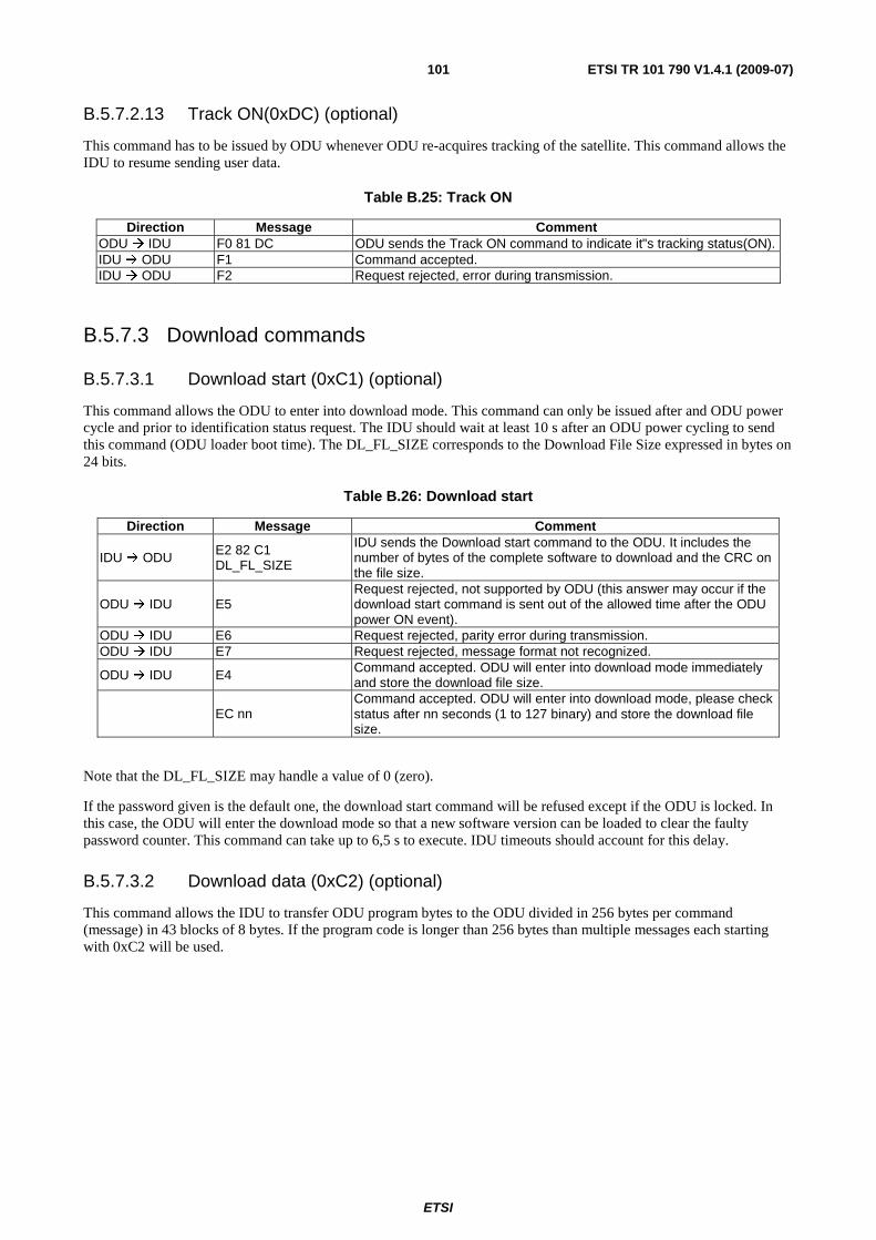
ETSI
ETSI TR 101 790 V1.4.1 (2009-07) 101
B.5.7.2.13 Track ON(0xDC) (optional)
This command has to be issued by ODU whenever ODU re-acquires tracking of the satellite. This command allows the IDU to resume sending user data.
Table B.25: Track ON
Direction Message Comment ODU IDU F0 81 DC ODU sends the Track ON command to indicate it"s tracking status(ON). IDU ODU F1 Command accepted. IDU ODU F2 Request rejected, error during transmission.
B.5.7.3 Download commands
B.5.7.3.1 Download start (0xC1) (optional)
This command allows the ODU to enter into download mode. This command can only be issued after and ODU power cycle and prior to identification status request. The IDU should wait at least 10 s after an ODU power cycling to send this command (ODU loader boot time). The DL_FL_SIZE corresponds to the Download File Size expressed in bytes on 24 bits.
Table B.26: Download start
Direction Message Comment
IDU ODU E2 82 C1 DL_FL_SIZE
IDU sends the Download start command to the ODU. It includes the number of bytes of the complete software to download and the CRC on the file size.
ODU IDU E5 Request rejected, not supported by ODU (this answer may occur if the download start command is sent out of the allowed time after the ODU power ON event).
ODU IDU E6 Request rejected, parity error during transmission. ODU IDU E7 Request rejected, message format not recognized.
ODU IDU E4 Command accepted. ODU will enter into download mode immediately and store the download file size.
EC nn Command accepted. ODU will enter into download mode, please check status after nn seconds (1 to 127 binary) and store the download file size.
Note that the DL_FL_SIZE may handle a value of 0 (zero).
If the password given is the default one, the download start command will be refused except if the ODU is locked. In this case, the ODU will enter the download mode so that a new software version can be loaded to clear the faulty password counter. This command can take up to 6,5 s to execute. IDU timeouts should account for this delay.
B.5.7.3.2 Download data (0xC2) (optional)
This command allows the IDU to transfer ODU program bytes to the ODU divided in 256 bytes per command (message) in 43 blocks of 8 bytes. If the program code is longer than 256 bytes than multiple messages each starting with 0xC2 will be used.
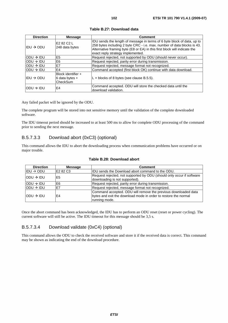
ETSI
ETSI TR 101 790 V1.4.1 (2009-07) 102
Table B.27: Download data
Direction Message Comment
IDU ODU E2 82 C2 L 248 data bytes
IDU sends the length of message in terms of 6 byte block of data, up to 258 bytes including 2 byte CRC - i.e. max. number of data blocks is 43. Alternative framing byte (E8 or EA) in this first block will indicate the exact reply strategy implemented.
ODU IDU E5 Request rejected, not supported by ODU (should never occur). ODU IDU E6 Request rejected, parity error during transmission. ODU IDU E7 Request rejected, message format not recognized. ODU IDU E4 Command accepted (first block OK) continue with data download.
IDU ODU Block identifier + 6 data bytes + CheckSum
L × blocks of 8 bytes (see clause B.5.5).
ODU IDU E4 Command accepted. ODU will store the checked data until the download validation.
Any failed packet will be ignored by the ODU.
The complete program will be stored into not sensitive memory until the validation of the complete downloaded software.
The IDU timeout period should be increased to at least 500 ms to allow for complete ODU processing of the command prior to sending the next message.
B.5.7.3.3 Download abort (0xC3) (optional)
This command allows the IDU to abort the downloading process when communication problems have occurred or on major trouble.
Table B.28: Download abort
Direction Message Comment IDU ODU E2 82 C3 IDU sends the Download abort command to the ODU.
ODU IDU E5 Request rejected, not supported by ODU (should only occur if software downloading is not supported).
ODU IDU E6 Request rejected, parity error during transmission. ODU IDU E7 Request rejected, message format not recognized.
ODU IDU E4 Command accepted. ODU will remove the previous downloaded data bytes and exit the download mode in order to restore the normal running mode.
Once the abort command has been acknowledged, the IDU has to perform an ODU reset (reset or power cycling). The current software will still be active. The IDU timeout for this message should be 3,5 s.
B.5.7.3.4 Download validate (0xC4) (optional)
This command allows the ODU to check the received software and store it if the received data is correct. This command may be shown as indicating the end of the download procedure.
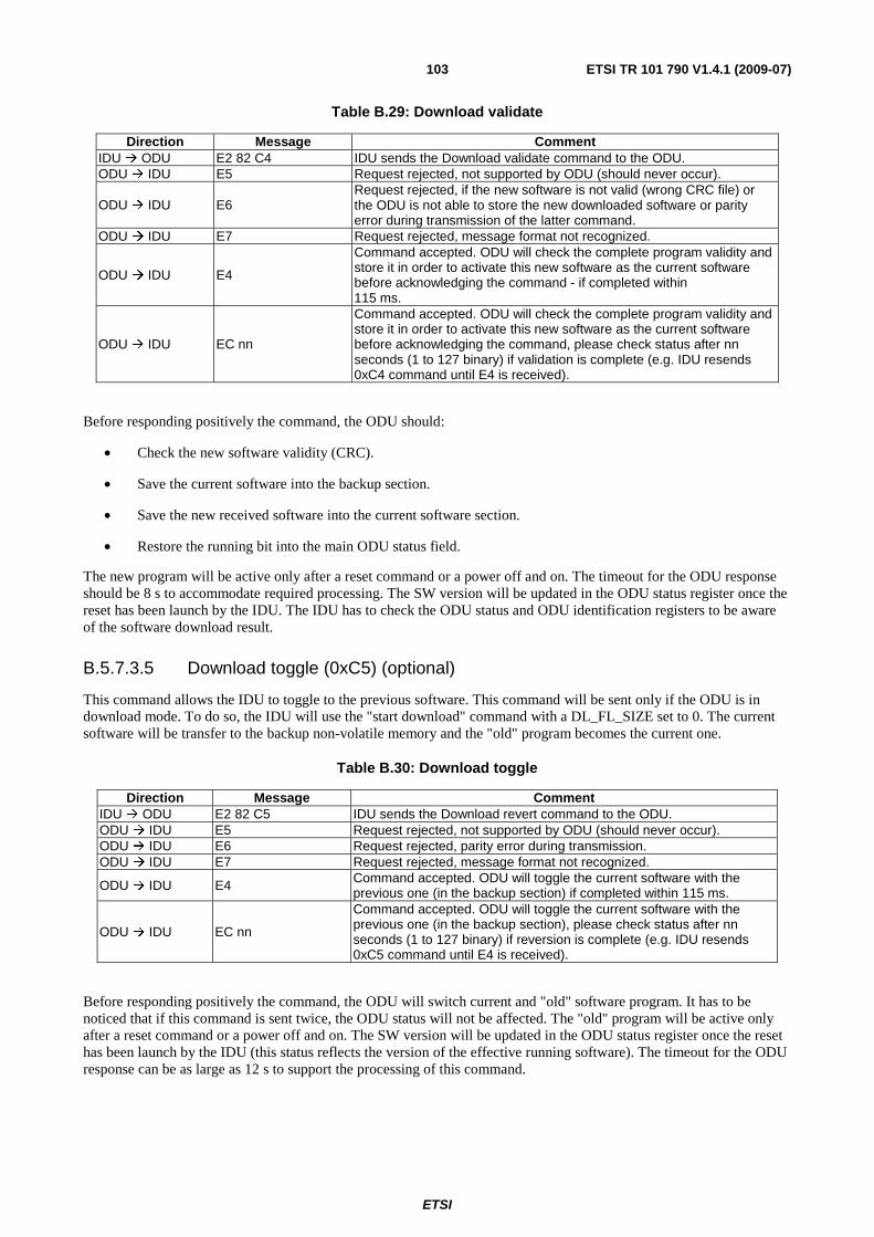
ETSI
ETSI TR 101 790 V1.4.1 (2009-07) 103
Table B.29: Download validate
Direction Message Comment IDU ODU E2 82 C4 IDU sends the Download validate command to the ODU. ODU IDU E5 Request rejected, not supported by ODU (should never occur).
ODU IDU E6 Request rejected, if the new software is not valid (wrong CRC file) or the ODU is not able to store the new downloaded software or parity error during transmission of the latter command.
ODU IDU E7 Request rejected, message format not recognized.
ODU IDU E4
Command accepted. ODU will check the complete program validity and store it in order to activate this new software as the current software before acknowledging the command - if completed within 115 ms.
ODU IDU EC nn
Command accepted. ODU will check the complete program validity and store it in order to activate this new software as the current software before acknowledging the command, please check status after nn seconds (1 to 127 binary) if validation is complete (e.g. IDU resends 0xC4 command until E4 is received).
Before responding positively the command, the ODU should:
• Check the new software validity (CRC).
• Save the current software into the backup section.
• Save the new received software into the current software section.
• Restore the running bit into the main ODU status field.
The new program will be active only after a reset command or a power off and on. The timeout for the ODU response should be 8 s to accommodate required processing. The SW version will be updated in the ODU status register once the reset has been launch by the IDU. The IDU has to check the ODU status and ODU identification registers to be aware of the software download result.
B.5.7.3.5 Download toggle (0xC5) (optional)
This command allows the IDU to toggle to the previous software. This command will be sent only if the ODU is in download mode. To do so, the IDU will use the "start download" command with a DL_FL_SIZE set to 0. The current software will be transfer to the backup non-volatile memory and the "old" program becomes the current one.
Table B.30: Download toggle
Direction Message Comment IDU ODU E2 82 C5 IDU sends the Download revert command to the ODU. ODU IDU E5 Request rejected, not supported by ODU (should never occur). ODU IDU E6 Request rejected, parity error during transmission. ODU IDU E7 Request rejected, message format not recognized.
ODU IDU E4 Command accepted. ODU will toggle the current software with the previous one (in the backup section) if completed within 115 ms.
ODU IDU EC nn
Command accepted. ODU will toggle the current software with the previous one (in the backup section), please check status after nn seconds (1 to 127 binary) if reversion is complete (e.g. IDU resends 0xC5 command until E4 is received).
Before responding positively the command, the ODU will switch current and "old" software program. It has to be noticed that if this command is sent twice, the ODU status will not be affected. The "old" program will be active only after a reset command or a power off and on. The SW version will be updated in the ODU status register once the reset has been launch by the IDU (this status reflects the version of the effective running software). The timeout for the ODU response can be as large as 12 s to support the processing of this command.
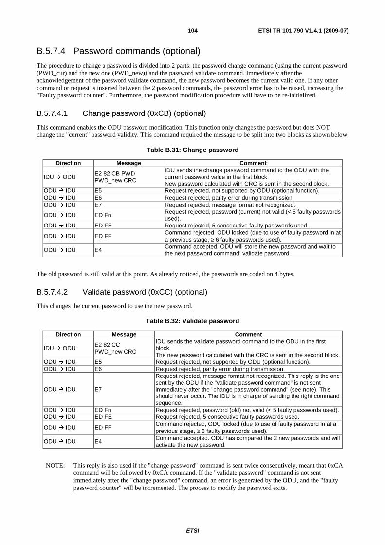
ETSI
ETSI TR 101 790 V1.4.1 (2009-07) 104
B.5.7.4 Password commands (optional)
The procedure to change a password is divided into 2 parts: the password change command (using the current password (PWD_cur) and the new one (PWD_new)) and the password validate command. Immediately after the acknowledgement of the password validate command, the new password becomes the current valid one. If any other command or request is inserted between the 2 password commands, the password error has to be raised, increasing the "Faulty password counter". Furthermore, the password modification procedure will have to be re-initialized.
B.5.7.4.1 Change password (0xCB) (optional)
This command enables the ODU password modification. This function only changes the password but does NOT change the "current" password validity. This command required the message to be split into two blocks as shown below.
Table B.31: Change password
Direction Message Comment
IDU ODU E2 82 CB PWD PWD_new CRC
IDU sends the change password command to the ODU with the current password value in the first block. New password calculated with CRC is sent in the second block.
ODU IDU E5 Request rejected, not supported by ODU (optional function). ODU IDU E6 Request rejected, parity error during transmission. ODU IDU E7 Request rejected, message format not recognized.
ODU IDU ED Fn Request rejected, password (current) not valid (< 5 faulty passwords used).
ODU IDU ED FE Request rejected, 5 consecutive faulty passwords used.
ODU IDU ED FF Command rejected, ODU locked (due to use of faulty password in at a previous stage, ≥ 6 faulty passwords used).
ODU IDU E4 Command accepted. ODU will store the new password and wait to the next password command: validate password.
The old password is still valid at this point. As already noticed, the passwords are coded on 4 bytes.
B.5.7.4.2 Validate password (0xCC) (optional)
This changes the current password to use the new password.
Table B.32: Validate password
Direction Message Comment
IDU ODU E2 82 CC PWD_new CRC
IDU sends the validate password command to the ODU in the first block. The new password calculated with the CRC is sent in the second block.
ODU IDU E5 Request rejected, not supported by ODU (optional function). ODU IDU E6 Request rejected, parity error during transmission.
ODU IDU E7
Request rejected, message format not recognized. This reply is the one sent by the ODU if the "validate password command" is not sent immediately after the "change password command" (see note). This should never occur. The IDU is in charge of sending the right command sequence.
ODU IDU ED Fn Request rejected, password (old) not valid (< 5 faulty passwords used). ODU IDU ED FE Request rejected, 5 consecutive faulty passwords used.
ODU IDU ED FF Command rejected, ODU locked (due to use of faulty password in at a previous stage, ≥ 6 faulty passwords used).
ODU IDU E4 Command accepted. ODU has compared the 2 new passwords and will activate the new password.
NOTE: This reply is also used if the "change password" command is sent twice consecutively, meant that 0xCA command will be followed by 0xCA command. If the "validate password" command is not sent immediately after the "change password" command, an error is generated by the ODU, and the "faulty password counter" will be incremented. The process to modify the password exits.
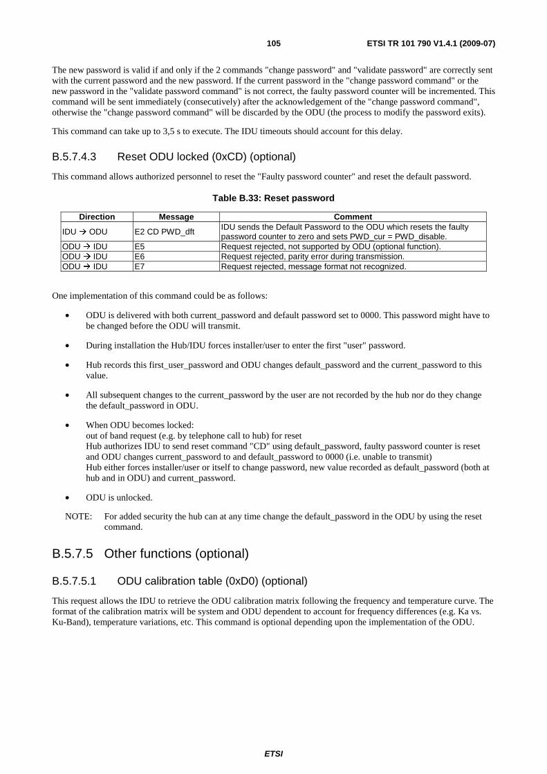
ETSI
ETSI TR 101 790 V1.4.1 (2009-07) 105
The new password is valid if and only if the 2 commands "change password" and "validate password" are correctly sent with the current password and the new password. If the current password in the "change password command" or the new password in the "validate password command" is not correct, the faulty password counter will be incremented. This command will be sent immediately (consecutively) after the acknowledgement of the "change password command", otherwise the "change password command" will be discarded by the ODU (the process to modify the password exits).
This command can take up to 3,5 s to execute. The IDU timeouts should account for this delay.
B.5.7.4.3 Reset ODU locked (0xCD) (optional)
This command allows authorized personnel to reset the "Faulty password counter" and reset the default password.
Table B.33: Reset password
Direction Message Comment
IDU ODU E2 CD PWD_dft IDU sends the Default Password to the ODU which resets the faulty password counter to zero and sets PWD_cur = PWD_disable.
ODU IDU E5 Request rejected, not supported by ODU (optional function). ODU IDU E6 Request rejected, parity error during transmission. ODU IDU E7 Request rejected, message format not recognized.
One implementation of this command could be as follows:
• ODU is delivered with both current_password and default password set to 0000. This password might have to be changed before the ODU will transmit.
• During installation the Hub/IDU forces installer/user to enter the first "user" password.
• Hub records this first_user_password and ODU changes default_password and the current_password to this value.
• All subsequent changes to the current_password by the user are not recorded by the hub nor do they change the default_password in ODU.
• When ODU becomes locked: out of band request (e.g. by telephone call to hub) for reset Hub authorizes IDU to send reset command "CD" using default_password, faulty password counter is reset and ODU changes current_password to and default_password to 0000 (i.e. unable to transmit) Hub either forces installer/user or itself to change password, new value recorded as default_password (both at hub and in ODU) and current_password.
• ODU is unlocked.
NOTE: For added security the hub can at any time change the default_password in the ODU by using the reset command.
B.5.7.5 Other functions (optional)
B.5.7.5.1 ODU calibration table (0xD0) (optional)
This request allows the IDU to retrieve the ODU calibration matrix following the frequency and temperature curve. The format of the calibration matrix will be system and ODU dependent to account for frequency differences (e.g. Ka vs. Ku-Band), temperature variations, etc. This command is optional depending upon the implementation of the ODU.
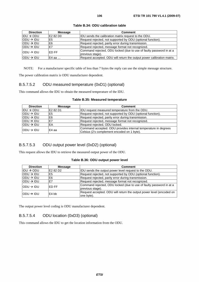
ETSI
ETSI TR 101 790 V1.4.1 (2009-07) 106
Table B.34: ODU calibration table
Direction Message Comment IDU ODU E2 82 D0 IDU sends the calibration matrix request to the ODU. ODU IDU E5 Request rejected, not supported by ODU (optional function). ODU IDU E6 Request rejected, parity error during transmission. ODU IDU E7 Request rejected, message format not recognized.
ODU IDU ED FF Command rejected, ODU locked (due to use of faulty password in at a previous stage).
ODU IDU E4 aa … Request accepted. ODU will return the output power calibration matrix.
NOTE: For a manufacturer specific table of less than 7 bytes the reply can use the simple message structure.
The power calibration matrix is ODU manufacturer dependent.
B.5.7.5.2 ODU measured temperature (0xD1) (optional)
This command allows the IDU to obtain the measured temperature of the IDU.
Table B.35: Measured temperature
Direction Message Comment IDU ODU E2 82 D1 IDU request measured temperature from the ODU. ODU IDU E5 Request rejected, not supported by ODU (optional function). ODU IDU E6 Request rejected, parity error during transmission. ODU IDU E7 Request rejected, message format not recognized. ODU IDU EA Request rejected, ODU locked.
ODU IDU E4 aa Command accepted. ODU provides internal temperature in degrees Celsius (2's complement encoded on 1 byte).
B.5.7.5.3 ODU output power level (0xD2) (optional)
This request allows the IDU to retrieve the measured output power of the ODU.
Table B.36: ODU output power level
Direction Message Comment IDU ODU E2 82 D2 IDU sends the output power level request to the ODU. ODU IDU E5 Request rejected, not supported by ODU (optional function). ODU IDU E6 Request rejected, parity error during transmission. ODU IDU E7 Request rejected, message format not recognized.
ODU IDU ED FF Command rejected, ODU locked (due to use of faulty password in at a previous stage).
ODU IDU E4 bb Request accepted. ODU will return the output power level (encoded on one byte).
The output power level coding is ODU manufacturer dependent.
B.5.7.5.4 ODU location (0xD3) (optional)
This command allows the IDU to get the location information from the ODU.
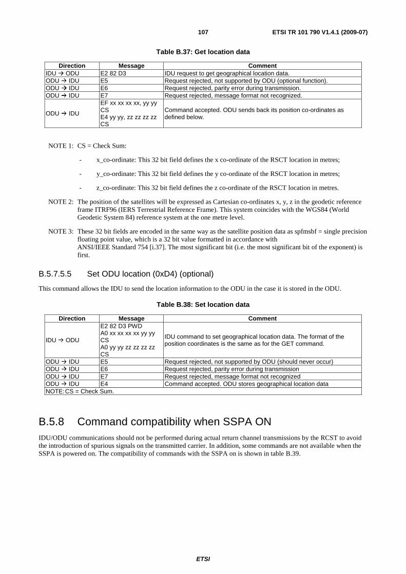
ETSI
ETSI TR 101 790 V1.4.1 (2009-07) 107
Table B.37: Get location data
Direction Message Comment IDU ODU E2 82 D3 IDU request to get geographical location data. ODU IDU E5 Request rejected, not supported by ODU (optional function). ODU IDU E6 Request rejected, parity error during transmission. ODU IDU E7 Request rejected, message format not recognized.
ODU IDU
EF xx xx xx xx, yy yy CS E4 yy yy, zz zz zz zz CS
Command accepted. ODU sends back its position co-ordinates as defined below.
NOTE 1: CS = Check Sum:
- x_co-ordinate: This 32 bit field defines the x co-ordinate of the RSCT location in metres;
- y_co-ordinate: This 32 bit field defines the y co-ordinate of the RSCT location in metres;
- z_co-ordinate: This 32 bit field defines the z co-ordinate of the RSCT location in metres.
NOTE 2: The position of the satellites will be expressed as Cartesian co-ordinates x, y, z in the geodetic reference frame ITRF96 (IERS Terrestrial Reference Frame). This system coincides with the WGS84 (World Geodetic System 84) reference system at the one metre level.
NOTE 3: These 32 bit fields are encoded in the same way as the satellite position data as spfmsbf = single precision floating point value, which is a 32 bit value formatted in accordance with ANSI/IEEE Standard 754 [i.37]. The most significant bit (i.e. the most significant bit of the exponent) is first.
B.5.7.5.5 Set ODU location (0xD4) (optional)
This command allows the IDU to send the location information to the ODU in the case it is stored in the ODU.
Table B.38: Set location data
Direction Message Comment
IDU ODU
E2 82 D3 PWD A0 xx xx xx xx yy yy CS A0 yy yy zz zz zz zz CS
IDU command to set geographical location data. The format of the position coordinates is the same as for the GET command.
ODU IDU E5 Request rejected, not supported by ODU (should never occur) ODU IDU E6 Request rejected, parity error during transmission ODU IDU E7 Request rejected, message format not recognized ODU IDU E4 Command accepted. ODU stores geographical location data NOTE: CS = Check Sum.
B.5.8 Command compatibility when SSPA ON IDU/ODU communications should not be performed during actual return channel transmissions by the RCST to avoid the introduction of spurious signals on the transmitted carrier. In addition, some commands are not available when the SSPA is powered on. The compatibility of commands with the SSPA on is shown in table B.39.
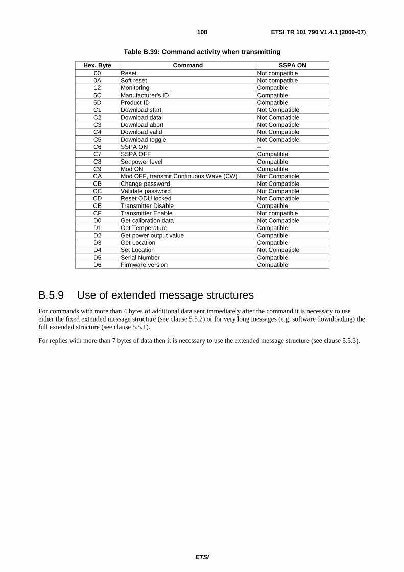
ETSI
ETSI TR 101 790 V1.4.1 (2009-07) 108
Table B.39: Command activity when transmitting
Hex. Byte Command SSPA ON 00 Reset Not compatible 0A Soft reset Not compatible 12 Monitoring Compatible 5C Manufacturer's ID Compatible 5D Product ID Compatible C1 Download start Not Compatible C2 Download data Not Compatible C3 Download abort Not Compatible C4 Download valid Not Compatible C5 Download toggle Not Compatible C6 SSPA ON -- C7 SSPA OFF Compatible C8 Set power level Compatible C9 Mod ON Compatible CA Mod OFF, transmit Continuous Wave (CW) Not Compatible CB Change password Not Compatible CC Validate password Not Compatible CD Reset ODU locked Not Compatible CE Transmitter Disable Compatible CF Transmitter Enable Not compatible D0 Get calibration data Not Compatible D1 Get Temperature Compatible D2 Get power output value Compatible D3 Get Location Compatible D4 Set Location Not Compatible D5 Serial Number Compatible D6 Firmware version Compatible
B.5.9 Use of extended message structures For commands with more than 4 bytes of additional data sent immediately after the command it is necessary to use either the fixed extended message structure (see clause 5.5.2) or for very long messages (e.g. software downloading) the full extended structure (see clause 5.5.1).
For replies with more than 7 bytes of data then it is necessary to use the extended message structure (see clause 5.5.3).
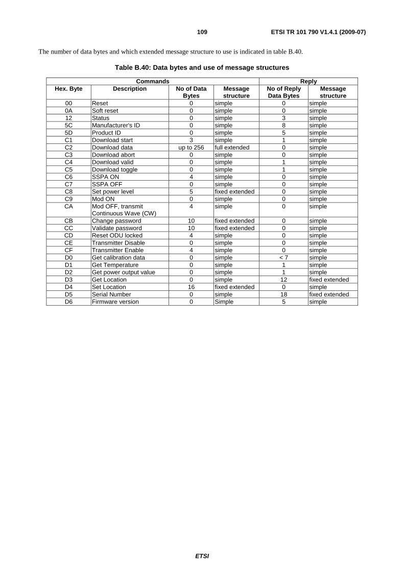
ETSI
ETSI TR 101 790 V1.4.1 (2009-07) 109
The number of data bytes and which extended message structure to use is indicated in table B.40.
Table B.40: Data bytes and use of message structures
Commands Reply Hex. Byte Description No of Data
Bytes Message structure
No of Reply Data Bytes
Message structure
00 Reset 0 simple 0 simple 0A Soft reset 0 simple 0 simple 12 Status 0 simple 3 simple 5C Manufacturer's ID 0 simple 8 simple 5D Product ID 0 simple 5 simple C1 Download start 3 simple 1 simple C2 Download data up to 256 full extended 0 simple C3 Download abort 0 simple 0 simple C4 Download valid 0 simple 1 simple C5 Download toggle 0 simple 1 simple C6 SSPA ON 4 simple 0 simple C7 SSPA OFF 0 simple 0 simple C8 Set power level 5 fixed extended 0 simple C9 Mod ON 0 simple 0 simple CA Mod OFF, transmit
Continuous Wave (CW) 4 simple 0 simple
CB Change password 10 fixed extended 0 simple CC Validate password 10 fixed extended 0 simple CD Reset ODU locked 4 simple 0 simple CE Transmitter Disable 0 simple 0 simple CF Transmitter Enable 4 simple 0 simple D0 Get calibration data 0 simple < 7 simple D1 Get Temperature 0 simple 1 simple D2 Get power output value 0 simple 1 simple D3 Get Location 0 simple 12 fixed extended D4 Set Location 16 fixed extended 0 simple D5 Serial Number 0 simple 18 fixed extended D6 Firmware version 0 Simple 5 simple
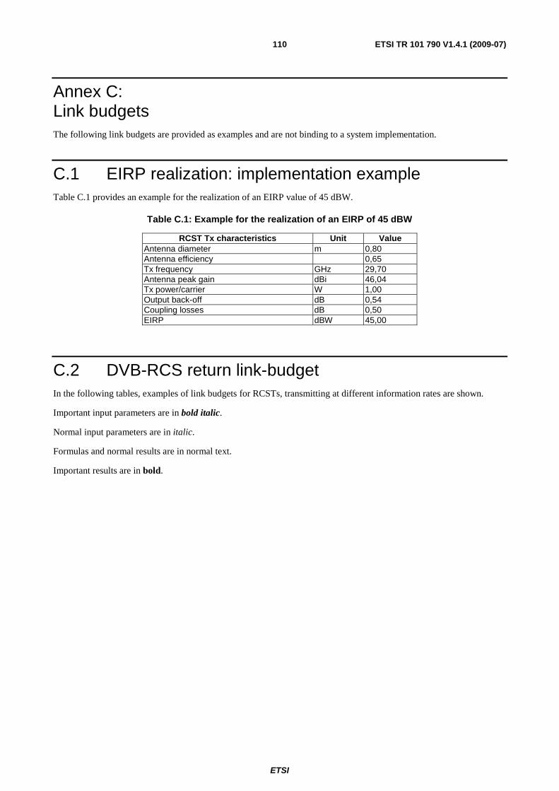
ETSI
ETSI TR 101 790 V1.4.1 (2009-07) 110
Annex C: Link budgets The following link budgets are provided as examples and are not binding to a system implementation.
C.1 EIRP realization: implementation example Table C.1 provides an example for the realization of an EIRP value of 45 dBW.
Table C.1: Example for the realization of an EIRP of 45 dBW
RCST Tx characteristics Unit Value Antenna diameter m 0,80 Antenna efficiency 0,65 Tx frequency GHz 29,70 Antenna peak gain dBi 46,04 Tx power/carrier W 1,00 Output back-off dB 0,54 Coupling losses dB 0,50 EIRP dBW 45,00
C.2 DVB-RCS return link-budget In the following tables, examples of link budgets for RCSTs, transmitting at different information rates are shown.
Important input parameters are in bold italic.
Normal input parameters are in italic.
Formulas and normal results are in normal text.
Important results are in bold.
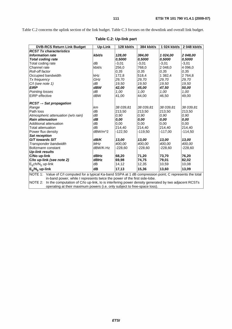
ETSI
ETSI TR 101 790 V1.4.1 (2009-07) 111
Table C.2 concerns the uplink section of the link budget. Table C.3 focuses on the downlink and overall link budget.
Table C.2: Up-link part
DVB-RCS Return Link Budget Up-Link 128 kbit/s 384 kbit/s 1 024 kbit/s 2 048 kbit/s RCST Tx characteristics Information rate kbit/s 128,00 384,00 1 024,00 2 048,00 Total coding rate 0,5000 0,5000 0,5000 0,5000 Total coding rate dB -3,01 -3,01 -3,01 -3,01 Channel rate kbit/s 256,0 768,0 2 048,0 4 096,0 Roll-off factor 0,35 0,35 0,35 0,35 Occupied bandwidth kHz 172,8 518,4 1 382,4 2 764,8 Tx frequency GHz 29,70 29,70 29,70 29,70 C/I (see note 1) dB 19,50 19,50 19,50 19,50 EIRP dBW 42,00 45,00 47,50 50,00 Pointing losses dB 1,00 1,00 1,00 1,00 EIRP effective dBW 41,00 44,00 46,50 49,00
RCST → Sat propagation Range km 38 039,81 38 039,81 38 039,81 38 039,81 Path loss dB 213,50 213,50 213,50 213,50 Atmospheric attenuation (w/o rain) dB 0,90 0,90 0,90 0,90 Rain attenuation dB 0,00 0,00 0,00 0,00 Additional attenuation dB 0,00 0,00 0,00 0,00 Total attenuation dB 214,40 214,40 214,40 214,40 Power flux density dBW/m^2 -122,50 -119,50 -117,00 -114,50 Sat reception G/T towards SIT dB/K 13,00 13,00 13,00 13,00 Transponder bandwidth MHz 400,00 400,00 400,00 400,00 Boltzmann constant dBW/K-Hz -228,60 -228,60 -228,60 -228,60 Up-link results C/No up-link dBHz 68,20 71,20 73,70 76,20 C/Io up-link (see note 2) dBHz 69,98 74,75 79,01 82,02 Ebch/N0 up-link dB 14,12 12,35 10,59 10,08 Eb/N0 up-link dB 17,13 15,36 13,60 13,09
NOTE 1: Value of C/I computed for a typical Ka-band SSPA at 1 dB compression point; C represents the total in-band power, while I represents twice the power of the first side-lobe.
NOTE 2: In the computation of C/Io up-link, Io is interfering power density generated by two adjacent RCSTs operating at their maximum powers (i.e. only subject to free-space loss).
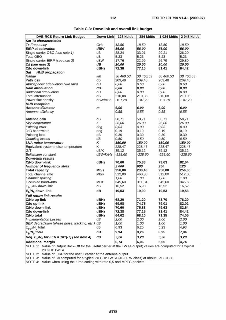
ETSI
ETSI TR 101 790 V1.4.1 (2009-07) 112
Table C.3: Downlink and overall link budget
DVB-RCS Return Link Budget Down-Link 128 kbit/s 384 kbit/s 1 024 kbit/s 2 048 kbit/s Sat Tx characteristics Tx Frequency GHz 18,50 18,50 18,50 18,50 EIRP at saturation dBW 56,00 56,00 56,00 56,00 Single carrier OBO (see note 1) dB 38,24 33,01 29,21 26,20 Total OBO dB 5,23 5,23 5,23 5,23 Single carrier EIRP (see note 2) dBW 17,76 22,99 26,79 29,80 C/I (see note 3) dB 20,00 20,00 20,00 20,00 C/Io down-link dBHz 72,38 77,15 81,41 84,42 Sat → HUB propagation Range km 38 460,53 38 460,53 38 460,53 38 460,53 Path loss dB 209,48 209,48 209,48 209,48 Atmospheric attenuation (w/o rain) dB 0,60 0,60 0,60 0,60 Rain attenuation dB 0,00 0,00 0,00 0,00 Additional attenuation dB 0,00 0,00 0,00 0,00 Total attenuation dB 210,08 210,08 210,08 210,08 Power flux density dBW/m^2 -107,29 -107,29 -107,29 -107,29 HUB reception Antenna diameter m 6,00 6,00 6,00 6,00 Antenna efficiency 0,55 0,55 0,55 0,55
Antenna gain dB 58,71 58,71 58,71 58,71 Sky temperature K 26,00 26,00 26,00 26,00 Pointing error deg 0,03 0,03 0,03 0,03 3dB beamwidth deg 0,19 0,19 0,19 0,19 Pointing loss dB 0,30 0,30 0,30 0,30 Coupling losses dB 0,50 0,50 0,50 0,50 LNA noise temperature K 150,00 150,00 150,00 150,00 Equivalent system noise temperature K 228,47 228,47 228,47 228,47 G/T dB/K 35,12 35,12 35,12 35,12 Boltzmann constant dBW/K/Hz -228,60 -228,60 -228,60 -228,60 Down-link results C/No down-link dBHz 70,60 75,83 79,63 82,64 Number of frequency slots 2 000 600 250 125 Total capacity Mb/s 256,00 230,40 256,00 256,00 Total channel rate Mb/s 512,00 460,80 512,00 512,00 Channel spacing 1,00 1,00 1,00 1,00 Occupied bandwidth MHz 345,60 311,04 345,60 345,60 Ebch/N0 down-link dB 16,52 16,98 16,52 16,52 Eb/N0 down-link dB 19,53 19,99 19,53 19,53 Full return link results C/No up-link dBHz 68,20 71,20 73,70 76,20 C/Io up-link dBHz 69,98 74,75 79,01 82,02 C/No down-link dBHz 70,60 75,83 79,63 82,64 C/Io down-link dBHz 72,38 77,15 81,41 84,42 C/No total dBHz 64,02 68,10 71,35 74,05 Implementation Losses dB 2,00 2,00 2,00 2,00 BER degradation (phase noise. tracking. etc.) dB 1,00 1,00 1,00 1,00 Ebch/N0 total dB 6,93 6,25 5,23 4,93 Eb/N0 total dB 9,94 9,26 8,25 7,94 Req. Eb/N0 for FER = 10^(-7) (see note 4) dB 3,20 3,20 3,20 3,20 Additional margin 6,74 6,06 5,05 4,74 NOTE 1: Value of Output Back-Off for the useful carrier at the TWTA output; values are computed for a typical
20 GHz TWTA. NOTE 2: Value of EIRP for the useful carrier at the antenna output. NOTE 3: Value of C/I computed for a typical 20 GHz TWTA (40-60 W class) at about 5 dB OBO. NOTE 4: Value when using the turbo coding with rate 0,5 and MPEG packets.
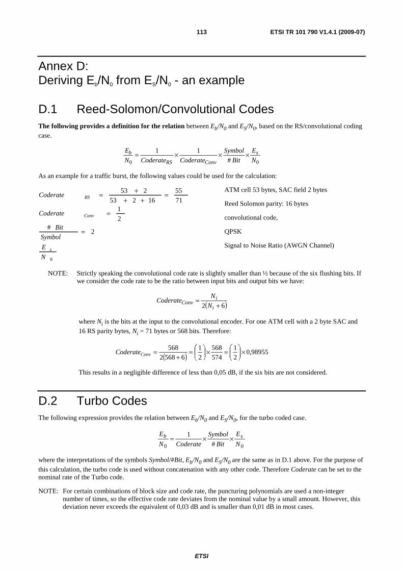
ETSI
ETSI TR 101 790 V1.4.1 (2009-07) 113
Annex D: Deriving Eb/N0 from ES/N0 - an example
D.1 Reed-Solomon/Convolutional Codes The following provides a definition for the relation between Eb/N0 and ES/N0, based on the RS/convolutional coding case.
00 #
11
N
E
Bit
Symbol
CoderateCoderateN
E s
ConvRS
b ×××=
As an example for a traffic burst, the following values could be used for the calculation:
0
2#
2
171
55
16253
253
N
E
Symbol
Bit
Coderate
Coderate
s
Conv
RS
=
=
=++
+=
ATM cell 53 bytes, SAC field 2 bytes
Reed Solomon parity: 16 bytes
convolutional code,
QPSK
Signal to Noise Ratio (AWGN Channel)
NOTE: Strictly speaking the convolutional code rate is slightly smaller than ½ because of the six flushing bits. If we consider the code rate to be the ratio between input bits and output bits we have:
( )62 +=
i
iConv N
NCoderate
where Ni is the bits at the input to the convolutional encoder. For one ATM cell with a 2 byte SAC and
16 RS parity bytes, Ni = 71 bytes or 568 bits. Therefore:
( ) 98955,02
1
574
568
2
1
65682
568 ×⎟⎠
⎞⎜⎝
⎛=×⎟⎠
⎞⎜⎝
⎛=+
=ConvCoderate
This results in a negligible difference of less than 0,05 dB, if the six bits are not considered.
D.2 Turbo Codes The following expression provides the relation between Eb/N0 and ES/N0, for the turbo coded case.
00 #
1
N
E
Bit
Symbol
CoderateN
E sb ××=
where the interpretations of the symbols Symbol/#Bit, Eb/N0 and ES/N0 are the same as in D.1 above. For the purpose of
this calculation, the turbo code is used without concatenation with any other code. Therefore Coderate can be set to the nominal rate of the Turbo code.
NOTE: For certain combinations of block size and code rate, the puncturing polynomials are used a non-integer number of times, so the effective code rate deviates from the nominal value by a small amount. However, this deviation never exceeds the equivalent of 0,03 dB and is smaller than 0,01 dB in most cases.
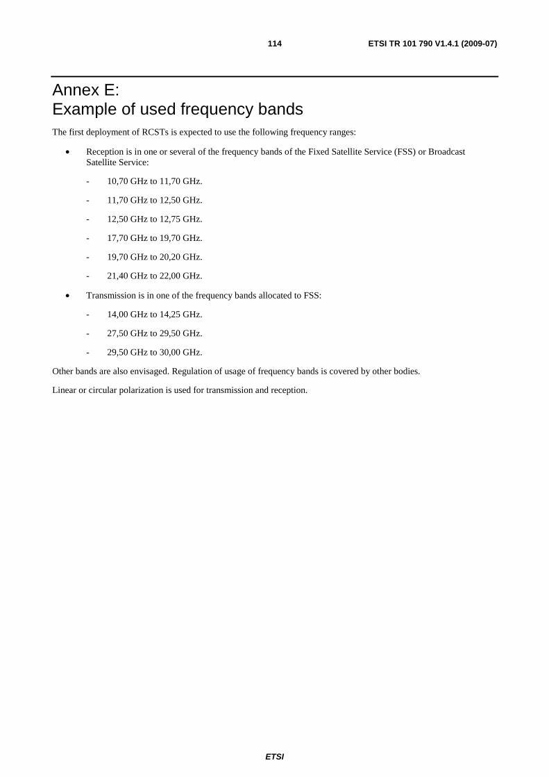
ETSI
ETSI TR 101 790 V1.4.1 (2009-07) 114
Annex E: Example of used frequency bands The first deployment of RCSTs is expected to use the following frequency ranges:
• Reception is in one or several of the frequency bands of the Fixed Satellite Service (FSS) or Broadcast Satellite Service:
- 10,70 GHz to 11,70 GHz.
- 11,70 GHz to 12,50 GHz.
- 12,50 GHz to 12,75 GHz.
- 17,70 GHz to 19,70 GHz.
- 19,70 GHz to 20,20 GHz.
- 21,40 GHz to 22,00 GHz.
• Transmission is in one of the frequency bands allocated to FSS:
- 14,00 GHz to 14,25 GHz.
- 27,50 GHz to 29,50 GHz.
- 29,50 GHz to 30,00 GHz.
Other bands are also envisaged. Regulation of usage of frequency bands is covered by other bodies.
Linear or circular polarization is used for transmission and reception.

ETSI
ETSI TR 101 790 V1.4.1 (2009-07) 115
Annex F: MIB definition SatLabs [i.52] is developing and maintaining a MIB dedicated to DVB-RCS terminals.
ETSI
ETSI TR 101 790 V1.4.1 (2009-07) 116
Annex G: Example for a security and authentication concept
G.1 User authentication using RADIUS This annex describes how users of an RCST can be authenticated by service providers in the satellite interactive network by applying RADIUS, which is specified in [i.7]. Users of an RCST are persons using an IP host that is connected to the RCST. Typically, a LAN connects one or more IP hosts to the RCST or a host is integrated with the RCST into one unit.
With authentication implemented in a satellite interactive network it is possible to restrict MAC layer capacity assignments or connection to other networks to RCSTs with authenticated users. In particular, users can authenticate to a service provider that provides them with connection to the Internet and in addition carries out the billing for the use of satellite interactive network resources. It is possible that different users behind an RCST authenticate to different service providers.
The RCST runs a web server that allows users to initiate authentication by means of a web browser running on their host. In cases where the RCST authenticates automatically without involvement of a user and a host, a static user can be configured on it. The user authentication as described here requires SNMP and the RCST MIB as defined in clause 8.5.
G.1.1 User authentication process The RCST receives a login request from the user on a host behind the RCST, or the RCST generates a login request for the Static Users, which are defined below. The User is identified by user id and password and optionally by a domain name. The domain name indicates the entity that does the authentication. In particular this can be a service provider. If a domain name is not provided, the RCST will append one. After the RCST gets the user information, it passes the user information to the NCC. NCC authenticates the user with the appropriate service provider. If its service provider accepts the user and the NCC is able to allocate resources to the RCST, the NCC allocates the RCST traffic resources of the CRA category and sends an access-accept message to the RCST. If the user is rejected by the service provider or the NCC is unable to allocate resources to the RCST, the NCC informs the RCST and sends an access-reject message to the RCST containing the reason for access rejection. The user authentication sub-system should provide the following:
• The RCST should implement a lightweight NAS module, which is called RADIUS User Client in the following, as a part of the RCST software offering. Modifications to standard RADIUS apply only to the link segment between the RADIUS User Client of the RCST and a specific device at the NCC, which is called RADIUS Client in the following. Standard RADIUS is used between the RADIUS Client and a RADIUS server or RADIUS proxy. Therefore, the solution interworks with standard radius servers of ISPs.
• The NCC will generate a "Random Number". This Random Number will be given to the RCST through the field "Random Number" of the Network Layer Info Descriptor. The Network Layer Info Descriptor is contained in the TIM message that the NCC sends as a reply to a CSC burst. The RCST will retain the Random Number and use it for all user authentications for the duration of a return link acquisition.
• The random number is used in a modified version of CHAP. The reason of circumventing standard CHAP is to require one round-trip less. Therefore, the user access to the network is shortened by about 520 ms in the case of geo-stationary satellites.
• The same Random Number will be used for all Access_Request messages for the duration of a return link acquisition.
• If the NCC sends an Access_Accept message to the RCST, then the RCST sends an "authenticated" message to the user. The user can then start sending traffic. At this stage the RCST will pass all traffic from the host this User authenticated from or from all hosts if there is a static user entry.
• RADIUS Challenge is not supported. If an ISP sends an Access_Challenge message, then the RADIUS client transforms it into an Access_Reject.
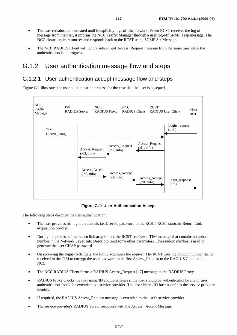
ETSI
ETSI TR 101 790 V1.4.1 (2009-07) 117
• The user remains authenticated until it explicitly logs off the network. When RCST receives the log off message from the user, it informs the NCC Traffic Manager through a user log-off SNMP Trap message. The NCC cleans-up its resources and responds back to the RCST using SNMP Set Message.
• The NCC RADIUS Client will ignore subsequent Access_Request message from the same user while the authentication is in progress.
G.1.2 User authentication message flow and steps
G.1.2.1 User authentication accept message flow and steps
Figure G.1 illustrates the user authentication process for the case that the user is accepted.
NCCRADIUS Client Host
user
RCSTRADIUS User Client
TIM(RAND, info)
NCCRADIUS Proxy
Access_Request(id1, info)Access_Request
(id2, info)
Access_Accept(id2,info) Access_Accept
(id1, info)Login_response(info)
NCC,TrafficManager
Access_Request(id3, info)
Access_Accept(id3, info)
ISPRADIUS Server
Login_request(info)
Figure G.1: User Authentication Accept
The following steps describe the user authentication:
• The user provides his login credentials i.e. User id, password to the RCST. RCST starts its Return Link acquisition process.
• During the process of the return link acquisition, the RCST receives a TIM message that contains a random number in the Network Layer Info Descriptor and some other parameters. The random number is used to generate the user CHAP password.
• On receiving the login credentials, the RCST examines the request. The RCST uses the random number that it received in the TIM to encrypt the user password in its first Access_Request to the RADIUS Client at the NCC.
• The NCC RADIUS Client forms a RADIUS Access_Request [i.7] message to the RADIUS Proxy.
• RADIUS Proxy checks the user name/ID and determines if the user should be authenticated locally or user authentication should be extended to a service provider. The User Name/ID format defines the service provider identity.
• If required, the RADIUS Access_Request message is extended to the user's service provider.
• The service provider's RADIUS Server responses with the Access_ Accept Message.
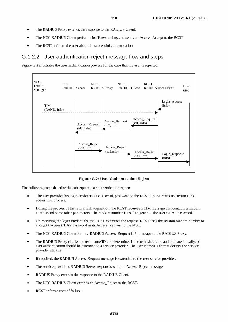
ETSI
ETSI TR 101 790 V1.4.1 (2009-07) 118
• The RADIUS Proxy extends the response to the RADIUS Client.
• The NCC RADIUS Client performs its IP resourcing, and sends an Access_Accept to the RCST.
• The RCST informs the user about the successful authentication.
G.1.2.2 User authentication reject message flow and steps
Figure G.2 illustrates the user authentication process for the case that the user is rejected.
NCCRADIUS Client Host
user
RCSTRADIUS User Client
TIM(RAND, info)
NCCRADIUS Proxy
Access_Request(id1, info)Access_Request
(id2, info)
Access_Reject(id2,info) Access_Reject
(id1, info)Login_response(info)
NCC,TrafficManager
Access_Request(id3, info)
Access_Reject(id3, info)
ISPRADIUS Server
Login_request(info)
Figure G.2: User Authentication Reject
The following steps describe the subsequent user authentication reject:
• The user provides his login credentials i.e. User id, password to the RCST. RCST starts its Return Link acquisition process.
• During the process of the return link acquisition, the RCST receives a TIM message that contains a random number and some other parameters. The random number is used to generate the user CHAP password.
• On receiving the login credentials, the RCST examines the request. RCST uses the session random number to encrypt the user CHAP password in its Access_Request to the NCC.
• The NCC RADIUS Client forms a RADIUS Access_Request [i.7] message to the RADIUS Proxy.
• The RADIUS Proxy checks the user name/ID and determines if the user should be authenticated locally, or user authentication should be extended to a service provider. The user Name/ID format defines the service provider identity.
• If required, the RADIUS Access_Request message is extended to the user service provider.
• The service provider's RADIUS Server responses with the Access_Reject message.
• RADIUS Proxy extends the response to the RADIUS Client.
• The NCC RADIUS Client extends an Access_Reject to the RCST.
• RCST informs user of failure.
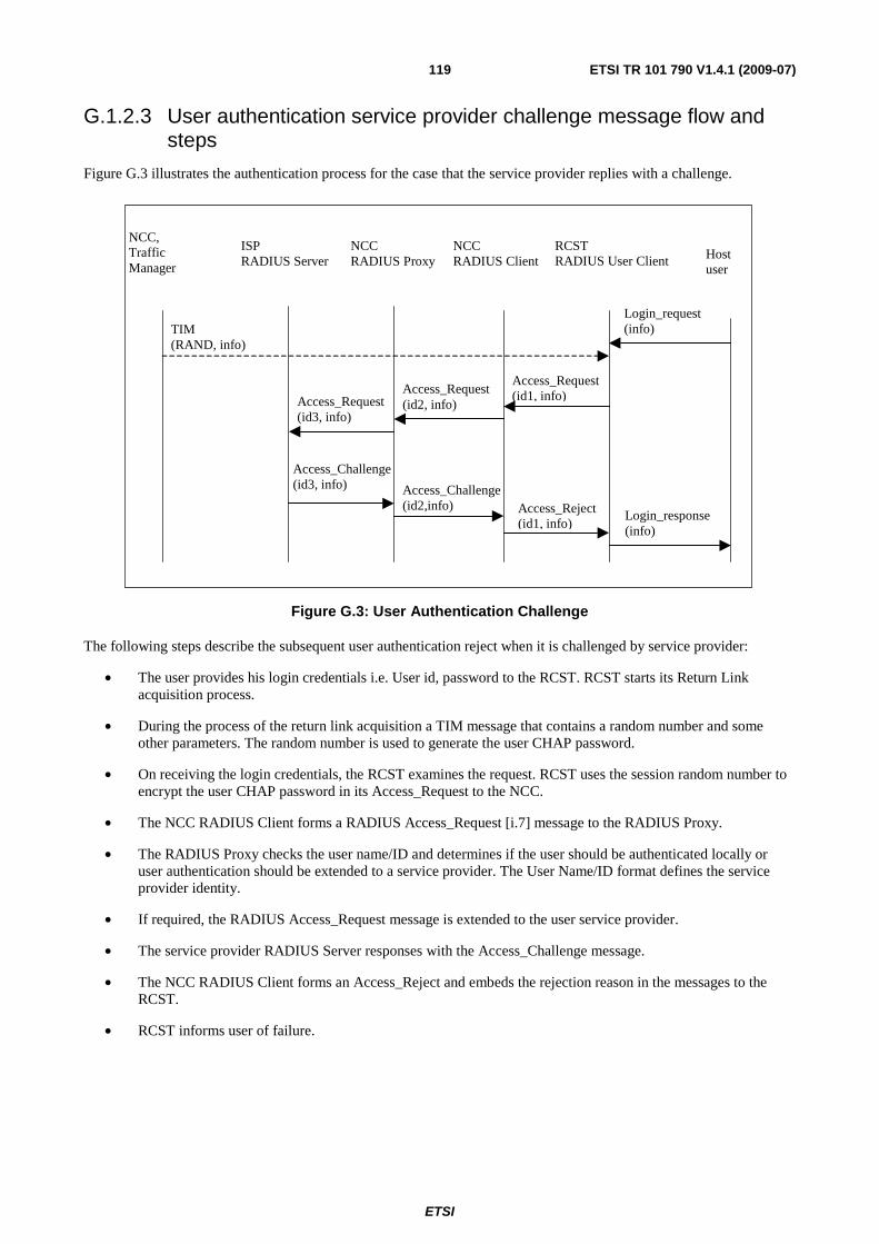
ETSI
ETSI TR 101 790 V1.4.1 (2009-07) 119
G.1.2.3 User authentication service provider challenge message flow and steps
Figure G.3 illustrates the authentication process for the case that the service provider replies with a challenge.
NCCRADIUS Client Host
user
RCSTRADIUS User Client
TIM(RAND, info)
NCCRADIUS Proxy
Access_Request(id1, info)Access_Request
(id2, info)
Access_Challenge(id2,info) Access_Reject
(id1, info)Login_response(info)
NCC,TrafficManager
Access_Request(id3, info)
Access_Challenge(id3, info)
ISPRADIUS Server
Login_request(info)
Figure G.3: User Authentication Challenge
The following steps describe the subsequent user authentication reject when it is challenged by service provider:
• The user provides his login credentials i.e. User id, password to the RCST. RCST starts its Return Link acquisition process.
• During the process of the return link acquisition a TIM message that contains a random number and some other parameters. The random number is used to generate the user CHAP password.
• On receiving the login credentials, the RCST examines the request. RCST uses the session random number to encrypt the user CHAP password in its Access_Request to the NCC.
• The NCC RADIUS Client forms a RADIUS Access_Request [i.7] message to the RADIUS Proxy.
• The RADIUS Proxy checks the user name/ID and determines if the user should be authenticated locally or user authentication should be extended to a service provider. The User Name/ID format defines the service provider identity.
• If required, the RADIUS Access_Request message is extended to the user service provider.
• The service provider RADIUS Server responses with the Access_Challenge message.
• The NCC RADIUS Client forms an Access_Reject and embeds the rejection reason in the messages to the RCST.
• RCST informs user of failure.
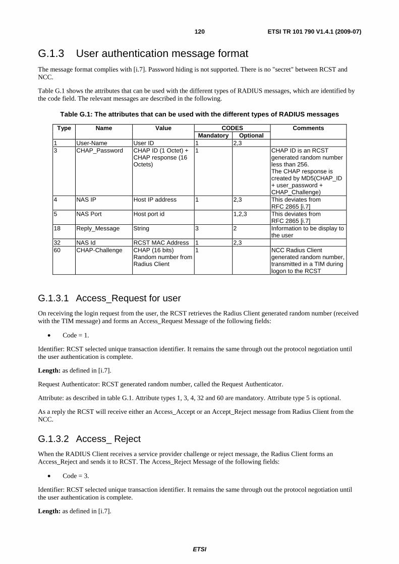
ETSI
ETSI TR 101 790 V1.4.1 (2009-07) 120
G.1.3 User authentication message format The message format complies with [i.7]. Password hiding is not supported. There is no "secret" between RCST and NCC.
Table G.1 shows the attributes that can be used with the different types of RADIUS messages, which are identified by the code field. The relevant messages are described in the following.
Table G.1: The attributes that can be used with the different types of RADIUS messages
CODES Type Name Value Mandatory Optional
Comments
1 User-Name User ID 1 2,3 3 CHAP_Password CHAP ID (1 Octet) +
CHAP response (16 Octets)
1 CHAP ID is an RCST generated random number less than 256. The CHAP response is created by MD5(CHAP_ID + user_password + CHAP_Challenge)
4 NAS IP Host IP address 1 2,3 This deviates from RFC 2865 [i.7]
5 NAS Port Host port id 1,2,3 This deviates from RFC 2865 [i.7]
18 Reply_Message String 3 2 Information to be display to the user
32 NAS Id RCST MAC Address 1 2,3 60 CHAP-Challenge CHAP (16 bits)
Random number from Radius Client
1 NCC Radius Client generated random number, transmitted in a TIM during logon to the RCST
G.1.3.1 Access_Request for user
On receiving the login request from the user, the RCST retrieves the Radius Client generated random number (received with the TIM message) and forms an Access_Request Message of the following fields:
• Code = 1.
Identifier: RCST selected unique transaction identifier. It remains the same through out the protocol negotiation until the user authentication is complete.
Length: as defined in [i.7].
Request Authenticator: RCST generated random number, called the Request Authenticator.
Attribute: as described in table G.1. Attribute types 1, 3, 4, 32 and 60 are mandatory. Attribute type 5 is optional.
As a reply the RCST will receive either an Access_Accept or an Accept_Reject message from Radius Client from the NCC.
G.1.3.2 Access_ Reject
When the RADIUS Client receives a service provider challenge or reject message, the Radius Client forms an Access_Reject and sends it to RCST. The Access_Reject Message of the following fields:
• Code = 3.
Identifier: RCST selected unique transaction identifier. It remains the same through out the protocol negotiation until the user authentication is complete.
Length: as defined in [i.7].
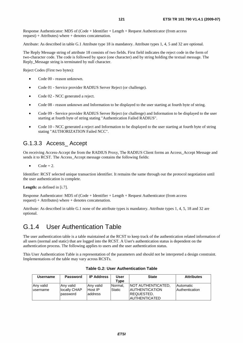
ETSI
ETSI TR 101 790 V1.4.1 (2009-07) 121
Response Authenticator: MD5 of (Code + Identifier + Length + Request Authenticator (from access request) + Attributes) where + denotes concatenation.
Attribute: As described in table G.1 Attribute type 18 is mandatory. Attribute types 1, 4, 5 and 32 are optional.
The Reply Message string of attribute 18 consists of two fields. First field indicates the reject code in the form of two-character code. The code is followed by space (one character) and by string holding the textual message. The Reply_Message string is terminated by null character.
Reject Codes (First two bytes):
• Code 00 - reason unknown.
• Code 01 - Service provider RADIUS Server Reject (or challenge).
• Code 02 - NCC generated a reject.
• Code 08 - reason unknown and Information to be displayed to the user starting at fourth byte of string.
• Code 09 - Service provider RADIUS Server Reject (or challenge) and Information to be displayed to the user starting at fourth byte of string stating "Authentication Failed RADIUS".
• Code 10 - NCC generated a reject and Information to be displayed to the user starting at fourth byte of string stating "AUTHORIZATION Failed NCC".
G.1.3.3 Access_ Accept
On receiving Access-Accept the from the RADIUS Proxy, The RADIUS Client forms an Access_Accept Message and sends it to RCST. The Access_Accept message contains the following fields:
• Code = 2.
Identifier: RCST selected unique transaction identifier. It remains the same through out the protocol negotiation until the user authentication is complete.
Length: as defined in [i.7].
Response Authenticator: MD5 of (Code + Identifier + Length + Request Authenticator (from access request) + Attributes) where + denotes concatenation.
Attribute: As described in table G.1 none of the attribute types is mandatory. Attribute types 1, 4, 5, 18 and 32 are optional.
G.1.4 User Authentication Table The user authentication table is a table maintained at the RCST to keep track of the authentication related information of all users (normal and static) that are logged into the RCST. A User's authentication status is dependent on the authentication process. The following applies to users and the user authentication status.
This User Authentication Table is a representation of the parameters and should not be interpreted a design constraint. Implementations of the table may vary across RCSTs.
Table G.2: User Authentication Table
Username Password IP Address User Type
State Attributes
Any valid username
Any valid locally CHAP password
Any valid Host IP address
Normal, Static
NOT AUTHENTICATED, AUTHENTICATION REQUESTED, AUTHENTICATED
Automatic Authentication
ETSI
ETSI TR 101 790 V1.4.1 (2009-07) 122
Username:
A character string used to uniquely identify a User within a domain. A user name can be qualified (such as <user>@<domain>).
The RCST will provide the following functionality:
• Default @domain.
The Superuser can enable/disable this mandatory feature and set the default @domain name. The default @domain name will be permanently stored in the RCST. The RCST will append the default @domain name to all unqualified logins.
• Enforced @domain.
This optional feature gives the possibility for the RCST to reject logins to any domain not specified as allowable in the RCST without sending a user login request to the NCC.
The installer is the only entity that can enable/disable this functionality and enter/modify the enforced @domain name. The enforced @domain name will be permanently stored in the RCST.
This concept can be extended to a list of authorized @domains (instead of a unique enforced @domain).
These two features can be run simultaneously on the same RCST. The @domain enforcement and default domain features might then be enabled and the default @domain name will then have to match the enforced @domain name.
Password:
Any character string, maximum 64 8-bit ASCII characters.
IP Address:
IP address of the host from which the user is logging in.
User Type:
Normal User:
All users who login from host machines behind the RCST using the HTML web pages located in the RCST.
Static User:
A Static User Entry is an entry in the RCST User Authentication Table that persists across RCST power cycles.
Only one entry exists in the User Authentication Table as a Static user entry.
Only a Superuser may define, remove or modify a Static User Entry. It is never removed from the User Authentication Table as part of the RCST system processes.
Static User entry has the Automatic Authentication attribute set upon creation.
If the RCST supports static user entry, then it blocks normal user logins (not Superuser). That is, the Static user and Normal users cannot exist together.
Removing a Static User and Adding Normal Users:
The Superuser removes the Static User from the User Authentication Table.
Normal users are added to the User Authentication Table as they login.
NOTE 1: The Superuser will force the user log off procedure when removing users of any type.
Removing Normal Users and Adding Static User:
The Superuser removes all Normal User from the User Authentication Table.
ETSI
ETSI TR 101 790 V1.4.1 (2009-07) 123
After all Normal Users are removed from the User Authentication Table, the Superuser adds the Static User to the User Authentication Table.
NOTE 2: The Superuser will force the user log off procedure when removing users of any type.
States:
All table entries will be in one of the following states:
• AUTHENTICATION REQUESTED.
• AUTHENTICATED.
• NOT AUTHENTICATED.
• AUTHENTICATION REQUESTED:
The user is AUTHENTICATION REQUESTED when the RCST starts the authentication process for the user until an authentication response from the NCC is received or authentication timeout expires.
AUTHENTICATED:
The user is AUTHENTICATED upon receiving the accept message from the NCC. At this point this user will also have the Automatic Authentication attribute set.
NOT AUTHENTICATED:
All users in the table for whom an authentication process has not been started.
NOTE 3: This includes static users for whom the authentication fails.
EXAMPLE 1: If the RCST is in the INITIALIZED state, a normal user entry may be in the NOT AUTHENTICATED state with the Automatic Authentication attribute set (as in the case when the normal user was authenticated at the time the RCST logs off the network).
EXAMPLE 2: If the RCST is in the INITIALIZED state, the static user will be in the NOT AUTHENTICATED state with the Automatic Authentication attribute set.
Attributes:
AUTOMATIC AUTHENTICATION ATTRIBUTE
Automatic Authentication Attribute for Normal Users.
When set, this attribute will trigger automatic authentication of a user entry in the UAT.
The purpose of this attribute is to signal the RCST about an automatic user authentication procedure upon the RCST's return link acquisition.
Automatic Authentication attribute for all normal users are initially defaulted to False.
The Automatic Authentication attribute is set when the user reaches the AUTHENTICATED state. This attribute remains set until the user entry is removed from the User Authentication table.
Automatic Authentication Attribute for Static Users.
Automatic Authentication attribute for a static user is set at the time when a static user is created and remain until the entry is removed.
Other User Authentication Table Properties:
• The User Authentication Table in the RCST can contain; either
• a single static entry; or
• one or more normal (non-static) entries.
ETSI
ETSI TR 101 790 V1.4.1 (2009-07) 124
A normal user is removed from the User Authentication Table when:
• The RCST transitions to the HOLD state.
• The User logs off (After the RCST receives the user log-off response from the NCC).
• Superuser removes the user entry from the User Authentication Table.
• The User fails authentication.
• Power is removed from the RCST or the RCST is reset.
• A Static User is removed from the User Authentication Table when:
• The Superuser removes the static user entry from the User Authentication Table.
G.1.5 CHAP password crypto engine To hide the password, this authentication process uses a method based on the RSA Message Digest Algorithm MD5. The algorithm takes as input a message of arbitrary length and produces as output a 128-bit "fingerprint" or "message digest" of the input. It is conjectured that it is computationally infeasible to produce two messages having the same message digest, or to produce any message having a given pre-specified target message digest. The MD5 algorithm is intended for digital signature applications.
The MD5 algorithm is designed to be quite fast on 32-bit machines. In addition, the MD5 algorithm does not require any large substitution tables; the algorithm can be coded quite compactly. Please refer to [i.20] for more detail on MD5.
RCST MD5 crypto Engine takes in three variables: user password, RCST generated CHAP ID, and NCC generated Random numbers and produces CHAP Password as output called "message digest" of the inputs. Details are specified in clause G.1.3.
G.2 IPSec solution and definition This clause describes an implementation of IPSec on DVB-RCS networks, together with parameter and option choices that are useful for this kind of networks. The objective is to provide to the end user default security on the satellite link and to prevent unauthorized eavesdropping of traffic. There are cases where the provision of such security is a legal requirement for network operators. It will be implemented in the RCST and the NCC, because they belong to the area that is controlled by the network operator. An implementation between two hosts or between a host and a service provider would not fulfil this requirement, but is possible in addition to the implementation described here. Security is also intended to protect the user's identity; including his exact location, signalling to and from the user, and the data traffic to and from the user. IPSec will protect some user identity such as IP address. Other user identity protection such as user authentication is defined elsewhere in the present document. The NCC will implement IPSec functionality though a security gateway, which is defined in RFC 2401 [i.21].
The RCSTs will implement IPSec software/hardware and function as peers to the NCC security gateway. The NCC security gateway policies should be statically configured to protect all networks behind the RCST with the RCST traffic IP addresses as its peer. Since a peer has one or more hosts behind it, the NCC security gateway is configured to be aware of the subnet behind each RCST. The peer configuration is not updateable on a real time basis.
The NCC secure tunnel, IKE SA, set-up is bi-directional. The RCST or the NCC security gateway can initiate the SA negotiation. The IPSec tunnel is set up between the NCC security gateway and RCSTs traffic interface. Once the secure tunnel is set up, only user traffic will be encrypted while OAM data will not be encrypted.
To summarize, IPSec sub-system will provide the following:
• Security gateway with tunnel mode to establish secure-connections from an RCST to the NCC.
• RCSTs that have IPSec software/hardware are peers to NCC security gateway.
• Support for Encapsulated Secure Payload (ESP), and single security association (SA) between RCST and NCC.
ETSI
ETSI TR 101 790 V1.4.1 (2009-07) 125
• The IPSec tunnel is established between an RCST and the NCC when RCST has traffic resources (traffic VCC), and the NCC and the RCST exchange user traffic.
• RCST traffic data is encrypted.
• RCST OAM data, i.e. SNMP using the RCST MIB, is not encrypted. The reason for not encrypting it is that building a tunnel before the RCST can start authenticating users would slow down the login process significantly because of the long roundtrip delay in conjunction with geo-stationary satellites.
• Peer to the NCC security gateway secure tunnels are statically configured.
• The SA re-negotiation life is configurable at both ends (security gateway, RCST). Negotiation re-keying time is determined by the shorter of the two configuration values.
• Both RCST and NCC will be IPSec interoperable.
• Both RCST and NCC will use same compression definition.
G.2.1 SA negotiation and secure tunnel setup A security association (SA) is a set of policy and key(s) used to protect information. The IKE SA is the shared policy and key(s) used by the negotiating peers in this protocol to protect their communication.
The SA negotiation takes place between the RCST and the NCC security gateway. The IP packets will have source address (RCST traffic IP address) and the destination address (the NCC security gateway IP address). All packets that use the RCST traffic IP address, as their source will be tunnelled to the NCC IPSec gateway.
SA Negotiation is considered IP traffic on traffic VCC, because of the relation between IPSec and the separation of control and traffic data within the constraints of the IP Topology. Specifically, all control data are filtered to go to the Control LAN. The traffic data is filtered to go to the security gateway. Hence, tunnel establishments will result in this split, regardless of what VCC is used.
In order to do SA negotiation/re-negotiation, the RCST will be in the Active state. This means, the Traffic resources (namely Traffic VCC) have been allocated to RCST.
The RCST will initiate the IPSec negotiation when the first user is authenticated and the RCST traffic resources are allocated. The RCST will undergo a state transition from OAM Active to Active state and initiate a secure association (SA) set-up. The IPSec negotiation will take place over the traffic channel and will be destined to the NCC security gateway using traffic IP address. Thereafter all hosts traffic data will be tunnelled to the NCC security gateway. To summarize the steps:
1) 1st user is authenticated successfully (Using OAM VCC).
2) RCST acquires Traffic resources.
3) RCST goes into Active state.
4) RCST starts IPSec negotiation (Using Traffic VCC).
Similarly, the NCC security gateway can initiate the IPSec negotiation, when data arrives from the terrestrial network and is destined to the host behind the RCST. It is RCST responsibility to reject or accept the dialog and negotiate back to the completion of SA set-up.
Once the secure tunnel is set up, only user traffic will be encrypted. Therefore, RCST will separate the user traffic from the OAM data. User traffic will be encrypted, and OAM data will not be encrypted.
G.2.2 RCST SA re-negotiation The SA re-negotiation life will be configurable at both ends (security gateway, RCST). Negotiation re-keying time is determined by the shorter of the two configuration values. If the RCST SA time-to-live expires, the RCST will re-negotiate the key. If the NCC security gateway SA time-to-live expires, the NCC starts re-negotiations. The re-negotiation to completion is determined by the RCST. RCSTs will only re-negotiate SA when they have their traffic resource; therefore, RCSTs will not acquire traffic VCC to re-negotiate their SA.
ETSI
ETSI TR 101 790 V1.4.1 (2009-07) 126
G.2.3 RCST Wake Up SA negotiation Traffic Wake up is initiated in the following manner. RCST is in the Initialized state with one or more users in the previously authenticated state. A return link acquisition will be triggered by the presence of unsent traffic in the RCSTs transmit buffer. Since the forward link is never surrendered, transmit buffers may get filled in response to a message from the NCC that was sent to an entity behind the RCST. Upon sensing unsent traffic the RCST goes through the OAM Acquisition and Traffic Acquisition procedure described in 8.5.3. Subsequent to the access request, the RCST would obtain the traffic VCC and then start the IP Sec tunnel establishment. An IPSec tunnel need be established only if a Secure Association does not exist or has expired. After the IPSec tunnel is established the traffic is sent as encrypted information directly to the security gateway.
G.2.3.1 RCST interfaces
RCSTs should statically be configured as peers to the NCC security gateway. The IP Address used for the NCC security gateway IP address will be the end-point at which the RCSTs terminate the IPSec tunnel. Encryption will be enabled to all traffic ports (if more than one).
G.2.4 Redundancy The peer Network (RCSTs) should support automatic roll-over from primary to secondary when primary security gateway failure. The roll-over timer should be configurable.
G.3 RCST security requirements This clause describes basic security requirements for an RCST, which enable a secure overall network. The RCST security should provide mechanisms for:
• Protection against violation.
• Detection of violation.
• Containment of violation.
• Recovery from violation.
G.3.1 Architecture overview The RCST should implement realms of access. A realm is defined as an area of functionality. Inside a particular realm, only certain actions may be taken and certain data accessed. The RCST implements six realms:
• Air Interface.
• NCC.
• Installer.
• Superuser.
• User.
• Service.
ETSI
ETSI TR 101 790 V1.4.1 (2009-07) 127
G.3.2 Protection against violation The RCST should provide protection against:
• Loss of Privacy - reading of information by unauthorized individuals.
• Loss of Data - the corruption or erasure of information.
Protection should be realized using a Login and Password mechanism.
Users provide login and password Identification to authenticate to the RCST. Factory defaults to no user accounts on the system.
The Superuser provides login and password identification to authenticate to the RCST. The Superuser account and password should be factory defaulted to predetermined values.
Installers have a pre-determined username and password combination to access the Installer Session Access screen.
If the RCST provides a web server for communication with the Users, Superuser and Installer, then Login sessions should take place using secure HTTP.
Installer Session Access - after installers have logged into the RCST with username and password they will be given a screen that presents the installer with the MAC address of the RCST and a Session Challenge. The same screen will ask for a session ID. The installer will take the MAC address, Session Challenge and their installer ID and then either call the network operator, use a special program or use special hardware to generate a session ID. The installer will then enter the session ID into the RCST. This will give access to the RCST for a particular session.
User Traffic Protection - no provision is made for user traffic protection, however RCST installation manuals should recommend the use of switched Ethernet to provide a measure of traffic protection.
G.3.3 Containment of violation Violations should be contained using the following mechanism:
Security Realms - RCST access is separated into five realms. A clear separation should be provided between security realms. Actions in each realm should be limited to those appropriate for those realms. Data access should be restricted for each realm as appropriate. Appropriate access for each realm to the SNMP MIB objects is defined as part of the MIB definition in clause 8.5. Transition from one realm to another should not be permitted.
G.3.4 Recovery from violation The NCC may be able to assist recovery from certain violations, however, some violations may require installer interaction.
It is strongly recommended that the RCST have the capability to display all super-user configurable parameters on a single screen, so that the super-user can keep a back up of configurable parameters.

ETSI
ETSI TR 101 790 V1.4.1 (2009-07) 128
Annex H: Void This annex is intentionally left blank.
ETSI
ETSI TR 101 790 V1.4.1 (2009-07) 129
Annex I: Example for procedures and operations providing additional functionality
I.1 RCST software download It is recommended to use the software download procedures that are recommended by SatLabs. These are defined in [i.52] and are based on SNMP, the DVB-RCS MIB, and MSDP (Multicast Software Download Protocol) protocols.
In particular:
• It defines how to locate the stream containing the system software update service in a network.
• It defines the signalling information used to locate the system software update service in a transport stream (via the PMT or MMT and the information part of the service).
• It defines the transmission of the actual system software update service as a standardized IP multicast.
• The protocol is based on OUIs (Organization Unique Identifier) for identifying manufacturer.
• It defines components that can be used to enhance the system software update functionality in an upward compatible way. This provides a standard mechanism for carrying additional information, e.g. update scheduling information, extensive selection and targeting information, action notification, filtering descriptors.
This solution offers all the required functionality as compared with the solution specified in [i.39], but eliminates the need for costly servers and complex software implementations in the RCST which are associated with the previously proposed techniques.
I.2 Installation and commissioning It is recommended to use the installation and commissioning procedures that have been specified by SatLabs. They are defined in [i.52] and are based on SNMP and the DVB-RCS MIB.
I.3 RCST system processes This clause provides a description of different processes represented in a hierarchical way. System processes are used to describe the system wide operations such as Login, Logoff, etc. The State Transition Processes are the processes that are used during transition from one state to another state (these are identified in the various state machines). The functional processes are used to describe a specific function.
These processes may affect several state machines and cover end-to-end system functions.
Note that a non-standard RADIUS is used between the RCST and the NCC. The standard RADIUS CHAP challenge mechanism is not used. Instead, the random number received from the TIM is used as the CHAP CHALLENGE in the encryption of the CHAP password. The reason for this deviation from standard RADIUS is the long transmission delay that is typical for geo-stationary satellites. Since each message exchange is delayed, the random number is transmitted once in a TIM during logon rather than by RADIUS CHAP challenge. This deviation from the standards applies only between the RCST and the NCC. Standard RADIUS and CHAP are used between the RADIUS Client at the NCC and the RADIUS server. Therefore, the existing RADIUS servers of Internet Service Providers can be used for authentication.
ETSI
ETSI TR 101 790 V1.4.1 (2009-07) 130
I.3.1 RCST Power On RCST Power-On is a User-initiated process that consists of the RCST going from its unpowered state to the INITIALIZED state as follows:
1) The User powers the RCST.
2) All RCST subsystems perform self-tests.
3) The RCST achieves the IDLE state.
4) The RCST acquires the Forward Link.
5) The RCST achieves the INITIALIZED state.
6) If the RCST was in the HOLD state before being powered off, it will return to the HOLD state.
Depending on the outdoor environmental conditions, the RCST transmit subsystem should need no more than one minute of warm-up time before it is ready to transmit. During this warm-up time, the RCST may transition to the INITIALIZED state. The user will be informed if the transmit subsystem is not ready.
I.3.2 RCST Reset RCST Reset is a process that can be initiated by the RCST, the NCC or the Superuser, and consists of the RCST going from its current state to the INITIALIZED state.
• The RCST may receive an RCST Reset command, either as an SNMP message from the NCC or over the web server from the Superuser or may determine to reset itself.
• The RCST prepares for reset (i.e. close file system, etc.).
• RCST subsystems reset as specified by the Reset command, and perform self-tests.
• The RCST achieves the IDLE state.
• The RCST acquires the Forward Link.
• The RCST achieves the INITIALIZED state.
If the RCST was in the HOLD state before being reset, it will return to the HOLD state.
I.3.3 RCST Login This is the process of the RCST going from INITIALIZED through OAM_ACTIVE to ACTIVE, one User going to AUTHENTICATED and the Secure Customer Device going from NO_ENCRYPT to ENCRYPT. If an accounting system is implemented in the satellite interactive network, then an RCST Login CDR is generated at the time the RCST transitions to OAM_ACTIVE.
I.3.4 RCST Re-login This is the process of the RCST re-acquiring the return link and synchronizing all the user states to send user traffic. User state synchronization involves the RCST re-authenticating all users who have their Automatic Authentication attribute set. In order to accomplish this, the RCST should contain at least one user in the User Authentication Table. If an accounting system is implemented in the satellite interactive network, then an RCST Login CDR is generated at the time the RCST transitions to OAM_ACTIVE.
ETSI
ETSI TR 101 790 V1.4.1 (2009-07) 131
I.3.5 RCST Logoff RCST Logoff is a process that can be initiated by the NCC or a Superuser, that consists of the RCST going from the ACTIVE state or the OAM ACTIVE state to the INITIALIZED state as follows:
1) The RCST is in the ACTIVE state or the OAM ACTIVE state.
2) When initiated by a Superuser, the Superuser selects the RCST Logoff command and provides appropriate authentication (User, Password) information if not already done so. The RCST sends an RCST Logoff Request to the NCC and waits for a confirmation from the NCC.
3) When initiated by the NCC, the RCST receives an RCST Logoff command from the NCC. An SNMP Response is sent back to the NCC; the converse of the previous step.
4) If the RCST is in ACTIVE state when it receives confirmation from the NCC (regardless of whether RCST Logoff was initiated by the NCC or the Superuser), the RCST and the NCC release the Traffic and OAM VCCs and associated TBTP assignments. Finally, the RCST returns to the INITIALIZED state.
5) If the RCST is in OAM ACTIVE state when it receives confirmation from the NCC (regardless of whether RCST Logoff was initiated by the NCC or the Superuser), the RCST and the NCC release the OAM VCC and associated TBTP assignment. Finally, the RCST returns to the INITIALIZED state.
6) The RCST goes to TxD and loses the Return Link, the NCC releases RCST Validation and Host Authentication information.
7) If the logoff process has been initiated by the Superuser, the Superuser has to be informed of the action by the web server.
I.3.6 RCST Wake Up RCST Wake up is the process of an RCST moving to either the OAM_ACTIVE or ACTIVE state to reply to forward link traffic. The exact RCST state depends on the type of traffic the RCST is replying to. The RCST transitions to the OAM_ACTIVE state to respond to OAM traffic. The RCST transitions to the ACTIVE state to forward unicast user traffic destined for a Host. For forwarding multicast traffic destined for hosts the RCST stays in the Initialized state.
I.3.6.1 Traffic initiated RCST Wake Up
Traffic Initiated RCST Wake up is the process of the RCST acquiring Return Link Traffic capacity (going from the INITIALIZED or OAM_ACTIVE states to ACTIVE state) when it has data in its traffic buffer that comes from a host responding to Forward Link traffic.
For Normal Users not logged into RCST, unicast traffic on forward and return link will be dropped.
For Normal and Static Users logged to the RCST but not authenticated with the NCC, traffic on forward link will be forwarded to the host and traffic on return link will be buffered until successful authentication.
Multicast traffic should be forwarded to users. RCST should honour all JOIN requests irrespective of user authentication status.
Requirements:
• The RCST will have at least one User with Automatic Authentication attribute set for this host IP address in the User Authentication Table. Note this can be a static User Entry.
• The RCST is configured to be "Wake-able" (in the NCC at service commissioning). The IP-DVB Gateway has a permanent entry for the RCST Secure Customer Device(s).
• Hosts behind the RCST have public IP addresses.
ETSI
ETSI TR 101 790 V1.4.1 (2009-07) 132
I.3.6.2 OAM RCST Wake Up
OAM RCST wake up is the process of the RCST acquiring Return Link capacity (going from the INITIALIZED to OAM_ACTIVE state) when it has data in its OAM buffer that comes from responding to Forward Link traffic.
I.3.7 RCST Disable The process of the RCST going from any state to INITIALIZED and then to the HOLD state. This process can be initiated by the NCC or Superuser as follows:
• When initiated by the Superuser, the Superuser selects the RCST Disable command from the RCSTs web page. The RCST then goes to the HOLD state.
• When initiated by the NCC, the RCST receives an RCST Logoff and Hold command as an SNMP message from the NCC and the RCST goes to the HOLD state.
NOTE: The RCST will store its current state in non-volatile memory and will recognize during power-on that it was last in the HOLD state and will transition to the HOLD state after performing self-tests and acquiring the Forward Link. The RCST will not pass forward link traffic to the user when in the HOLD state.
I.3.8 RCST Enable The process of the RCST going from HOLD to INITIALIZED state Only the entity (NCC, Superuser) that placed the RCST in the HOLD state can take it out of the HOLD state.
I.3.9 User Login The process of a user going from NOT AUTHENTICATED to AUTHENTICATED state. This may cause the RCST Login process to be executed.
I.3.10 User Logoff The process of a user going from AUTHENTICATED to NOT AUTHENTICATED state. This may cause the RCST to initiate the Traffic Release process (if there are no more static or dynamic users in the user authentication table). For a normal user, the user logoff is generated when the user logs off on the web page or when the Superuser removes the entry. For static users, the user logoff is generated when the Superuser removes the entry.
I.4 State transition processes The State transition processes describing the RCST Operations State Machine, Encryption, RCST Transmission, and Host Configuration State Machine should comply with the following specifications.
The table in clause I.4.1 is a legend for subsequent tables.
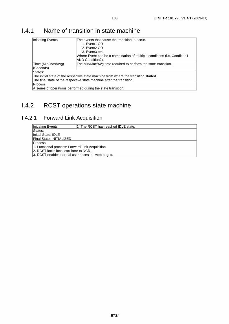
ETSI
ETSI TR 101 790 V1.4.1 (2009-07) 133
I.4.1 Name of transition in state machine Initiating Events The events that cause the transition to occur.
1. Event1 OR 2. Event2 OR 3. Event3 etc. Where Event can be a combination of multiple conditions (i.e. Condition1 AND Condition2).
Time (Min/Max/Avg) (Seconds)
The Min/Max/Avg time required to perform the state transition.
States: The initial state of the respective state machine from where the transition started. The final state of the respective state machine after the transition. Process: A series of operations performed during the state transition.
I.4.2 RCST operations state machine
I.4.2.1 Forward Link Acquisition
Initiating Events 1. The RCST has reached IDLE state. States: Initial State: IDLE Final State: INITIALIZED Process: 1. Functional process: Forward Link Acquisition. 2. RCST locks local oscillator to NCR. 3. RCST enables normal user access to web pages.
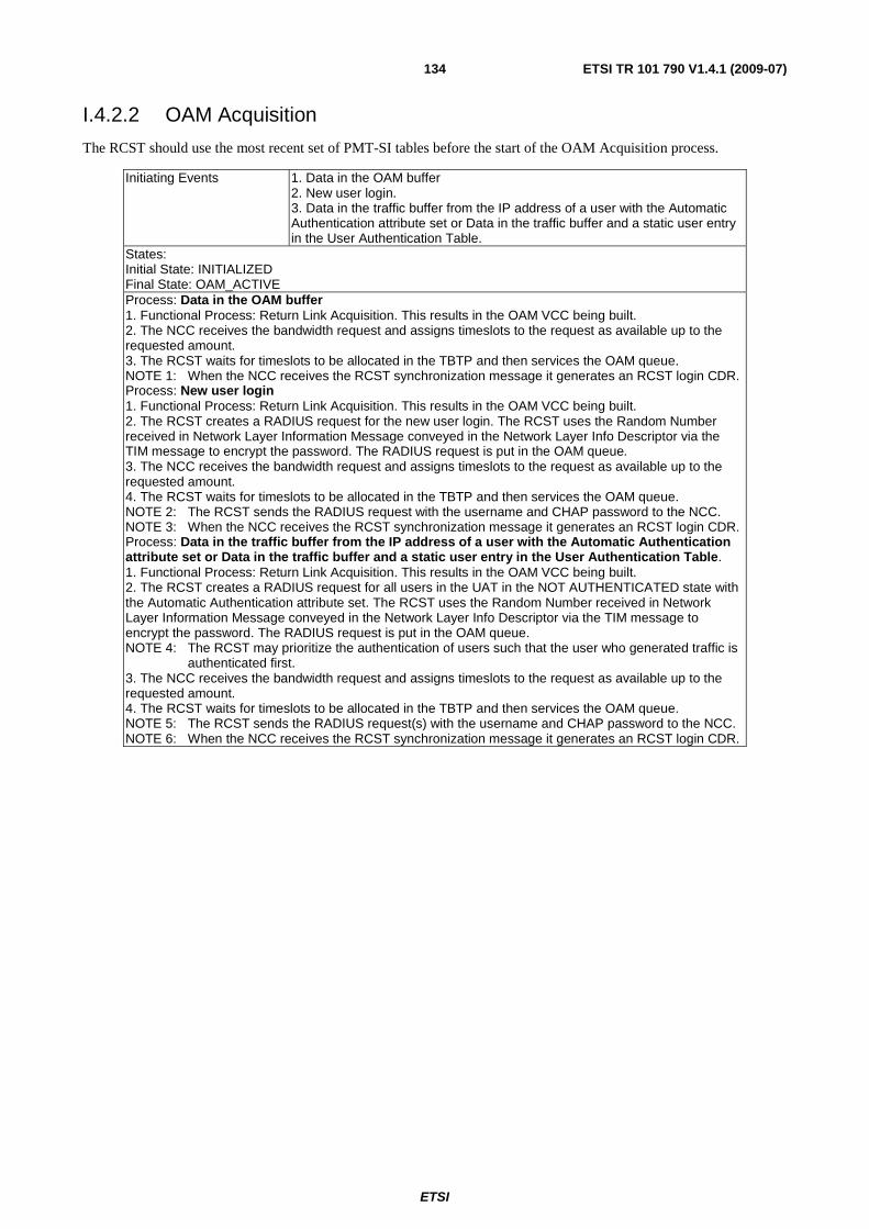
ETSI
ETSI TR 101 790 V1.4.1 (2009-07) 134
I.4.2.2 OAM Acquisition
The RCST should use the most recent set of PMT-SI tables before the start of the OAM Acquisition process.
Initiating Events 1. Data in the OAM buffer 2. New user login. 3. Data in the traffic buffer from the IP address of a user with the Automatic Authentication attribute set or Data in the traffic buffer and a static user entry in the User Authentication Table.
States: Initial State: INITIALIZED Final State: OAM_ACTIVE Process: Data in the OAM buffer 1. Functional Process: Return Link Acquisition. This results in the OAM VCC being built. 2. The NCC receives the bandwidth request and assigns timeslots to the request as available up to the requested amount. 3. The RCST waits for timeslots to be allocated in the TBTP and then services the OAM queue. NOTE 1: When the NCC receives the RCST synchronization message it generates an RCST login CDR. Process: New user login 1. Functional Process: Return Link Acquisition. This results in the OAM VCC being built. 2. The RCST creates a RADIUS request for the new user login. The RCST uses the Random Number received in Network Layer Information Message conveyed in the Network Layer Info Descriptor via the TIM message to encrypt the password. The RADIUS request is put in the OAM queue. 3. The NCC receives the bandwidth request and assigns timeslots to the request as available up to the requested amount. 4. The RCST waits for timeslots to be allocated in the TBTP and then services the OAM queue. NOTE 2: The RCST sends the RADIUS request with the username and CHAP password to the NCC. NOTE 3: When the NCC receives the RCST synchronization message it generates an RCST login CDR. Process: Data in the traffic buffer from the IP address of a user with the Automatic Authentication attribute set or Data in the traffic buffer and a static user entry in the User Authentication Table. 1. Functional Process: Return Link Acquisition. This results in the OAM VCC being built. 2. The RCST creates a RADIUS request for all users in the UAT in the NOT AUTHENTICATED state with the Automatic Authentication attribute set. The RCST uses the Random Number received in Network Layer Information Message conveyed in the Network Layer Info Descriptor via the TIM message to encrypt the password. The RADIUS request is put in the OAM queue. NOTE 4: The RCST may prioritize the authentication of users such that the user who generated traffic is
authenticated first. 3. The NCC receives the bandwidth request and assigns timeslots to the request as available up to the requested amount. 4. The RCST waits for timeslots to be allocated in the TBTP and then services the OAM queue. NOTE 5: The RCST sends the RADIUS request(s) with the username and CHAP password to the NCC. NOTE 6: When the NCC receives the RCST synchronization message it generates an RCST login CDR.
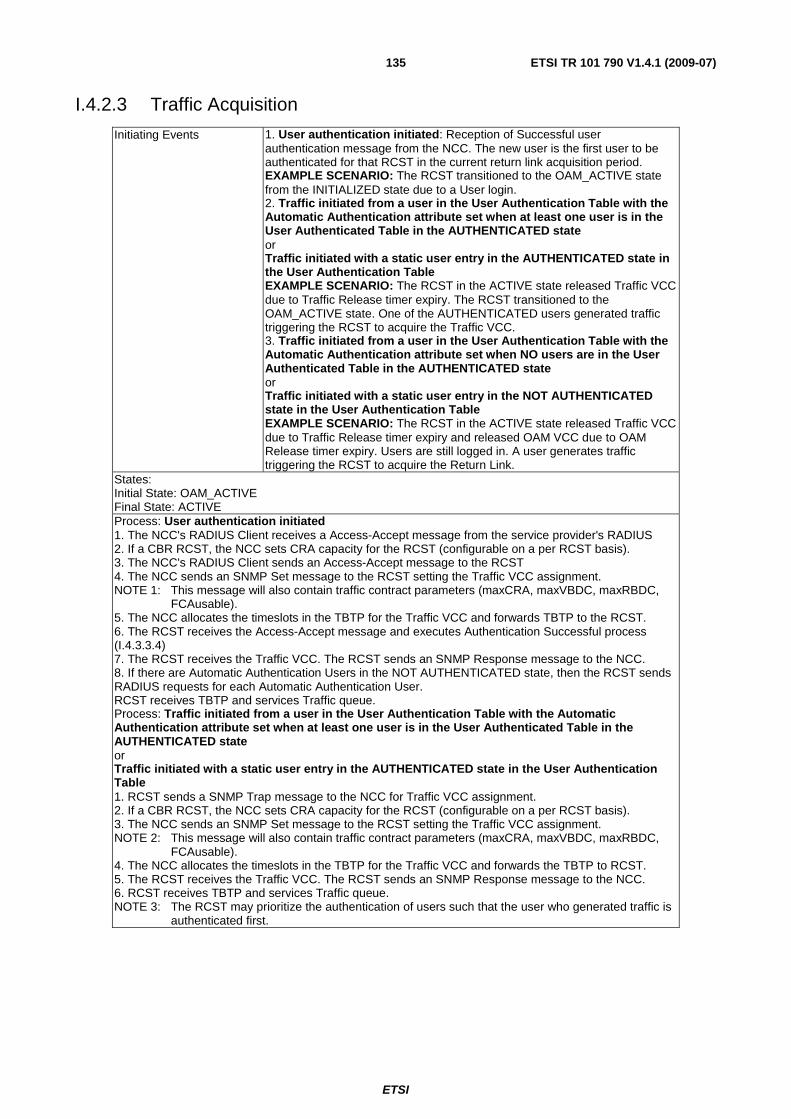
ETSI
ETSI TR 101 790 V1.4.1 (2009-07) 135
I.4.2.3 Traffic Acquisition
Initiating Events 1. User authentication initiated: Reception of Successful user authentication message from the NCC. The new user is the first user to be authenticated for that RCST in the current return link acquisition period. EXAMPLE SCENARIO: The RCST transitioned to the OAM_ACTIVE state from the INITIALIZED state due to a User login. 2. Traffic initiated from a user in the User Authentication Table with the Automatic Authentication attribute set when at least one user is in the User Authenticated Table in the AUTHENTICATED state or Traffic initiated with a static user entry in the AUTHENTICATED state in the User Authentication Table EXAMPLE SCENARIO: The RCST in the ACTIVE state released Traffic VCC due to Traffic Release timer expiry. The RCST transitioned to the OAM_ACTIVE state. One of the AUTHENTICATED users generated traffic triggering the RCST to acquire the Traffic VCC. 3. Traffic initiated from a user in the User Authentication Table with the Automatic Authentication attribute set when NO users are in the User Authenticated Table in the AUTHENTICATED state or Traffic initiated with a static user entry in the NOT AUTHENTICATED state in the User Authentication Table EXAMPLE SCENARIO: The RCST in the ACTIVE state released Traffic VCC due to Traffic Release timer expiry and released OAM VCC due to OAM Release timer expiry. Users are still logged in. A user generates traffic triggering the RCST to acquire the Return Link.
States: Initial State: OAM_ACTIVE Final State: ACTIVE Process: User authentication initiated 1. The NCC's RADIUS Client receives a Access-Accept message from the service provider's RADIUS 2. If a CBR RCST, the NCC sets CRA capacity for the RCST (configurable on a per RCST basis). 3. The NCC's RADIUS Client sends an Access-Accept message to the RCST 4. The NCC sends an SNMP Set message to the RCST setting the Traffic VCC assignment. NOTE 1: This message will also contain traffic contract parameters (maxCRA, maxVBDC, maxRBDC,
FCAusable). 5. The NCC allocates the timeslots in the TBTP for the Traffic VCC and forwards TBTP to the RCST. 6. The RCST receives the Access-Accept message and executes Authentication Successful process (I.4.3.3.4) 7. The RCST receives the Traffic VCC. The RCST sends an SNMP Response message to the NCC. 8. If there are Automatic Authentication Users in the NOT AUTHENTICATED state, then the RCST sends RADIUS requests for each Automatic Authentication User. RCST receives TBTP and services Traffic queue. Process: Traffic initiated from a user in the User Authentication Table with the Automatic Authentication attribute set when at least one user is in the User Authenticated Table in the AUTHENTICATED state or Traffic initiated with a static user entry in the AUTHENTICATED state in the User Authentication Table 1. RCST sends a SNMP Trap message to the NCC for Traffic VCC assignment. 2. If a CBR RCST, the NCC sets CRA capacity for the RCST (configurable on a per RCST basis). 3. The NCC sends an SNMP Set message to the RCST setting the Traffic VCC assignment. NOTE 2: This message will also contain traffic contract parameters (maxCRA, maxVBDC, maxRBDC,
FCAusable). 4. The NCC allocates the timeslots in the TBTP for the Traffic VCC and forwards the TBTP to RCST. 5. The RCST receives the Traffic VCC. The RCST sends an SNMP Response message to the NCC. 6. RCST receives TBTP and services Traffic queue. NOTE 3: The RCST may prioritize the authentication of users such that the user who generated traffic is
authenticated first.
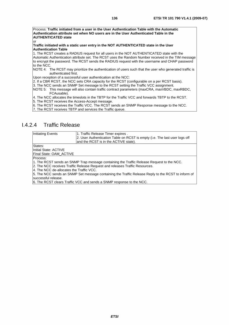
ETSI
ETSI TR 101 790 V1.4.1 (2009-07) 136
Process: Traffic initiated from a user in the User Authentication Table with the Automatic Authentication attribute set when NO users are in the User Authenticated Table in the AUTHENTICATED state or Traffic initiated with a static user entry in the NOT AUTHENTICATED state in the User Authentication Table 1. The RCST creates a RADIUS request for all users in the NOT AUTHENTICATED state with the Automatic Authentication attribute set. The RCST uses the Random Number received in the TIM message to encrypt the password. The RCST sends the RADIUS request with the username and CHAP password to the NCC. NOTE 4: The RCST may prioritize the authentication of users such that the user who generated traffic is
authenticated first. Upon reception of a successful user authentication at the NCC: 2. If a CBR RCST, the NCC sets CRA capacity for the RCST (configurable on a per RCST basis). 3. The NCC sends an SNMP Set message to the RCST setting the Traffic VCC assignment. NOTE 5: This message will also contain traffic contract parameters (maxCRA, maxVBDC, maxRBDC,
FCAusable). 4. The NCC allocates the timeslots in the TBTP for the Traffic VCC and forwards TBTP to the RCST. 5. The RCST receives the Access-Accept message. 6. The RCST receives the Traffic VCC. The RCST sends an SNMP Response message to the NCC. 7. The RCST receives TBTP and services the Traffic queue.
I.4.2.4 Traffic Release
Initiating Events 1. Traffic Release Timer expires . 2. User Authentication Table on RCST is empty (i.e. The last user logs off and the RCST is in the ACTIVE state).
States: Initial State: ACTIVE Final State: OAM_ACTIVE Process: 1. The RCST sends an SNMP Trap message containing the Traffic Release Request to the NCC. 2. The NCC receives Traffic Release Request and releases Traffic Resources. 4. The NCC de-allocates the Traffic VCC. 5. The NCC sends an SNMP Set message containing the Traffic Release Reply to the RCST to inform of successful release. 6. The RCST clears Traffic VCC and sends a SNMP response to the NCC.
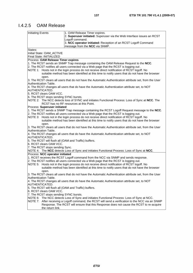
ETSI
ETSI TR 101 790 V1.4.1 (2009-07) 137
I.4.2.5 OAM Release
Initiating Events 1. OAM Release Timer expires. 2. Superuser initiated: Superuser via the Web Interface issues an RCST Logoff command. 3. NCC operator initiated: Reception of an RCST Logoff Command message from the NCC via SNMP.
States: Initial State: OAM_ACTIVE Final State: INITIALIZED Process: OAM Release Timer expires 1. The RCST sends an SNMP Trap message containing the OAM Release Request to the NCC. 2. The RCST notifies all users connected via a Web page that the RCST is logging out . NOTE 1: Hosts not in the login process do not receive direct notification of RCST logoff. No
suitable method has been identified at this time to notify users that do not have the browser open.
3. The RCST clears all users that do not have the Automatic Authentication attribute set, from the User Authentication Table. 4. The RCST changes all users that do have the Automatic Authentication attribute set, to NOT AUTHENTICATED. 5. RCST clears OAM VCC. 6. The RCST stops sending SYNC bursts. NOTE 2: The NCC detects loss of SYNC and initiates Functional Process: Loss of Sync at NCC. The
RCST has no RF resources at this Point. Process: Superuser initiated 1. The RCST sends a SNMP Trap message containing the RCST Logoff Request message to the NCC. 2. The RCST notifies all users connected via a Web page that the RCST is logging out. NOTE 3: Hosts not in the login process do not receive direct notification of RCST logoff. No
suitable method has been identified at this time to notify users that do not have the browser open.
3. The RCST clears all users that do not have the Automatic Authentication attribute set, from the User Authentication Table. 4. The RCST changes all users that do have the Automatic Authentication attribute set, to NOT AUTHENTICATED. 5. The RCST will flush all (OAM and Traffic) buffers. 6. RCST clears OAM VCC. 7. The RCST stops sending Sync. NOTE 4: The NCC detects Loss of Sync and initiates Functional Process: Loss of Sync at NCC. Process: NCC operator initiated 1. RCST receives the RCST Logoff command from the NCC via SNMP and sends response. 2. The RCST notifies all users connected via a Web page that the RCST is logging out. NOTE 5: Hosts not in the login process do not receive direct notification of RCST logoff. No
suitable method has been identified at this time to notify users that do not have the browser open.
3. The RCST clears all users that do not have the Automatic Authentication attribute set, from the User Authentication Table. 4. The RCST changes all users that do have the Automatic Authentication attribute set, to NOT AUTHENTICATED. 5. The RCST will flush all (OAM and Traffic) buffers. 6. RCST clears OAM VCC. 7. The RCST stops sending SYNC bursts. NOTE 6: The NCC detects Loss of Sync and initiates Functional Process: Loss of Sync at NCC. NOTE 7: After receiving a Logoff command, the RCST will send a verification to the NCC via an SNMP
Response. The RCST will ensure that this Response does not cause the RCST to re-acquire the return link.
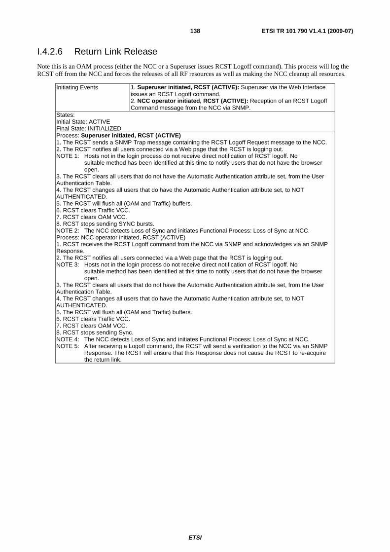
ETSI
ETSI TR 101 790 V1.4.1 (2009-07) 138
I.4.2.6 Return Link Release
Note this is an OAM process (either the NCC or a Superuser issues RCST Logoff command). This process will log the RCST off from the NCC and forces the releases of all RF resources as well as making the NCC cleanup all resources.
Initiating Events 1. Superuser initiated, RCST (ACTIVE): Superuser via the Web Interface issues an RCST Logoff command. 2. NCC operator initiated, RCST (ACTIVE): Reception of an RCST Logoff Command message from the NCC via SNMP.
States: Initial State: ACTIVE Final State: INITIALIZED Process: Superuser initiated, RCST (ACTIVE) 1. The RCST sends a SNMP Trap message containing the RCST Logoff Request message to the NCC. 2. The RCST notifies all users connected via a Web page that the RCST is logging out. NOTE 1: Hosts not in the login process do not receive direct notification of RCST logoff. No
suitable method has been identified at this time to notify users that do not have the browser open.
3. The RCST clears all users that do not have the Automatic Authentication attribute set, from the User Authentication Table. 4. The RCST changes all users that do have the Automatic Authentication attribute set, to NOT AUTHENTICATED. 5. The RCST will flush all (OAM and Traffic) buffers. 6. RCST clears Traffic VCC. 7. RCST clears OAM VCC. 8. RCST stops sending SYNC bursts. NOTE 2: The NCC detects Loss of Sync and initiates Functional Process: Loss of Sync at NCC. Process: NCC operator initiated, RCST (ACTIVE) 1. RCST receives the RCST Logoff command from the NCC via SNMP and acknowledges via an SNMP Response. 2. The RCST notifies all users connected via a Web page that the RCST is logging out. NOTE 3: Hosts not in the login process do not receive direct notification of RCST logoff. No
suitable method has been identified at this time to notify users that do not have the browser open.
3. The RCST clears all users that do not have the Automatic Authentication attribute set, from the User Authentication Table. 4. The RCST changes all users that do have the Automatic Authentication attribute set, to NOT AUTHENTICATED. 5. The RCST will flush all (OAM and Traffic) buffers. 6. RCST clears Traffic VCC. 7. RCST clears OAM VCC. 8. RCST stops sending Sync. NOTE 4: The NCC detects Loss of Sync and initiates Functional Process: Loss of Sync at NCC. NOTE 5: After receiving a Logoff command, the RCST will send a verification to the NCC via an SNMP
Response. The RCST will ensure that this Response does not cause the RCST to re-acquire the return link.
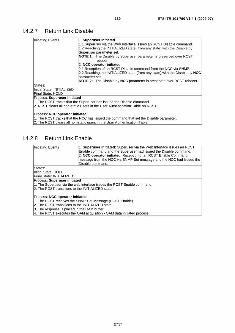
ETSI
ETSI TR 101 790 V1.4.1 (2009-07) 139
I.4.2.7 Return Link Disable
Initiating Events 1. Superuser initiated 1.1 Superuser via the Web Interface issues an RCST Disable command. 1.2 Reaching the INITIALIZED state (from any state) with the Disable by Superuser parameter set. NOTE 1: The Disable by Superuser parameter is preserved over RCST
reboots. 2. NCC operator initiated 2.1 Reception of an RCST Disable command from the NCC via SNMP. 2.2 Reaching the INITIALIZED state (from any state) with the Disable by NCC parameter set. NOTE 2: The Disable by NCC parameter is preserved over RCST reboots.
States: Initial State: INITIALIZED Final State: HOLD Process: Superuser initiated 1. The RCST tracks that the Superuser has issued the Disable command. 2. RCST clears all non-static Users in the User Authentication Table on RCST. Process: NCC operator initiated 1. The RCST tracks that the NCC has issued the command that set the Disable parameter. 2. The RCST clears all non-static users in the User Authentication Table.
I.4.2.8 Return Link Enable
Initiating Events 1. Superuser initiated: Superuser via the Web Interface issues an RCST Enable command and the Superuser had issued the Disable command. 2. NCC operator initiated: Reception of an RCST Enable Command message from the NCC via SNMP Set message and the NCC had issued the Disable command.
States: Initial State: HOLD Final State: INITIALIZED Process: Superuser initiated 1. The Superuser via the web interface issues the RCST Enable command. 2. The RCST transitions to the INITIALIZED state. Process: NCC operator initiated 1. The RCST receives the SNMP Set Message (RCST Enable). 2. The RCST transitions to the INITIALIZED state. 3. The response is placed in the OAM buffer. 4. The RCST executes the OAM acquisition - OAM data initiated process.
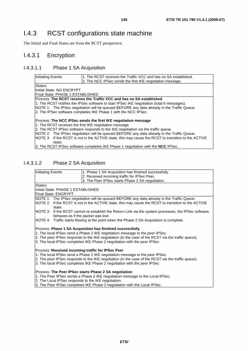
ETSI
ETSI TR 101 790 V1.4.1 (2009-07) 140
I.4.3 RCST configurations state machine The Initial and Final States are from the RCST perspective.
I.4.3.1 Encryption
I.4.3.1.1 Phase 1 SA Acquisition
Initiating Events 1. The RCST receives the Traffic VCC and has no SA established. 2. The NCC IPSec sends the first IKE negotiation message.
States: Initial State: NO ENCRYPT Final State: PHASE 1 ESTABLISHED Process: The RCST receives the Traffic VCC and has no SA established 1. The RCST notifies the IPSec software to start IPSec IKE negotiation (total 6 messages). NOTE 1: The IPSec negotiation will be queued BEFORE any data already in the Traffic Queue. 2. The IPSec software completes IKE Phase 1 with the NCC IPSec. Process: The NCC IPSec sends the first IKE negotiation message 1. The RCST receives the first IKE negotiation message. 2. The RCST IPSec software responds to the IKE negotiation via the traffic queue. NOTE 2: The IPSec negotiation will be queued BEFORE any data already in the Traffic Queue. NOTE 3: If the RCST is not in the ACTIVE state, this may cause the RCST to transition to the ACTIVE
state. 3. The RCST IPSec software completes IKE Phase 1 negotiation with the NCC IPSec.
I.4.3.1.2 Phase 2 SA Acquisition
Initiating Events 1. Phase 1 SA Acquisition has finished successfully. 2. Received incoming traffic for IPSec Peer. 3. The Peer IPSec starts Phase 2 SA negotiation.
States: Initial State: PHASE 1 ESTABLISHED Final State: ENCRYPT NOTE 1: The IPSec negotiation will be queued BEFORE any data already in the Traffic Queue. NOTE 2: If the RCST is not in the ACTIVE state, this may cause the RCST to transition to the ACTIVE
state. NOTE 3: If the RCST cannot re-establish the Return Link via the system processes, the IPSec software
behaves as if the packet was lost. NOTE 4: Traffic starts flowing at the point when the Phase 2 SA Acquisition is complete. Process: Phase 1 SA Acquisition has finished successfully 1. The local IPSec send a Phase 2 IKE negotiation message to the peer IPSec. 2. The peer IPSec responds to the IKE negotiation (in the case of the RCST via the traffic queue). 3. The local IPSec completes IKE Phase 2 negotiation with the peer IPSec Process: Received incoming traffic for IPSec Peer 1. The local IPSec send a Phase 2 IKE negotiation message to the peer IPSec. 2. The peer IPSec responds to the IKE negotiation (in the case of the RCST via the traffic queue). 3. The local IPSec completes IKE Phase 2 negotiation with the peer IPSec Process: The Peer IPSec starts Phase 2 SA negotiation 1. The Peer IPSec sends a Phase 2 IKE negotiation message to the Local IPSec. 2. The Local IPSec responds to the IKE negotiation. 3. The Peer IPSec completes IKE Phase 2 negotiation with the Local IPSec.
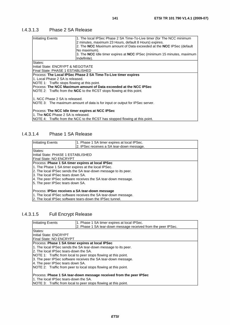
ETSI
ETSI TR 101 790 V1.4.1 (2009-07) 141
I.4.3.1.3 Phase 2 SA Release
Initiating Events 1. The local IPSec Phase 2 SA Time-To-Live timer (for The NCC minimum 2 minutes, maximum 23 Hours, default 8 Hours) expires. 2. The NCC Maximum amount of Data exceeded at the NCC IPSec (default No maximum). 3. The NCC Idle timer expires at NCC IPSec (minimum 15 minutes, maximum Indefinite).
States: Initial State: ENCRYPT & NEGOTIATE Final State: PHASE 1 ESTABLISHED Process: The Local IPSec Phase 2 SA Time-To-Live timer expires 1. Local Phase 2 SA is released. NOTE 1: Traffic stops flowing at this point. Process: The NCC Maximum amount of Data exceeded at the NCC IPSec NOTE 2: Traffic from the NCC to the RCST stops flowing at this point. 1. NCC Phase 2 SA is released. NOTE 3: The maximum amount of data is for input or output for IPSec server. Process: The NCC Idle timer expires at NCC IPSec 1. The NCC Phase 2 SA is released. NOTE 4: Traffic from the NCC to the RCST has stopped flowing at this point.
I.4.3.1.4 Phase 1 SA Release
Initiating Events 1. Phase 1 SA timer expires at local IPSec. 2. IPSec receives a SA tear-down message.
States: Initial State: PHASE 1 ESTABLISHED Final State: NO ENCRYPT Process: Phase 1 SA timer expires at local IPSec 1. The Phase 1 SA timer expires at the local IPSec. 2. The local IPSec sends the SA tear-down message to its peer. 3. The local IPSec tears down SA. 4. The peer IPSec software receives the SA tear-down message. 5. The peer IPSec tears down SA. Process: IPSec receives a SA tear-down message 1. The local IPSec software receives the SA tear-down message. 2. The local IPSec software tears-down the IPSec tunnel.
I.4.3.1.5 Full Encrypt Release
Initiating Events 1. Phase 1 SA timer expires at local IPSec. 2. Phase 1 SA tear-down message received from the peer IPSec.
States: Initial State: ENCRYPT Final State: NO ENCRYPT Process: Phase 1 SA timer expires at local IPSec 1. The local IPSec sends the SA tear-down message to its peer. 2. The local IPSec tears-down the SA. NOTE 1: Traffic from local to peer stops flowing at this point. 3. The peer IPSec software receives the SA tear-down message. 4. The peer IPSec tears down SA. NOTE 2: Traffic from peer to local stops flowing at this point. Process: Phase 1 SA tear-down message received from the peer IPSec 1. The local IPSec tears-down the SA. NOTE 3: Traffic from local to peer stops flowing at this point.
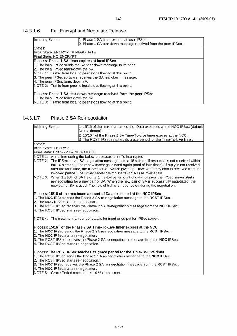
ETSI
ETSI TR 101 790 V1.4.1 (2009-07) 142
I.4.3.1.6 Full Encrypt and Negotiate Release
Initiating Events 1. Phase 1 SA timer expires at local IPSec. 2. Phase 1 SA tear-down message received from the peer IPSec.
States: Initial State: ENCRYPT & NEGOTIATE Final State: NO ENCRYPT Process: Phase 1 SA timer expires at local IPSec 1. The local IPSec sends the SA tear-down message to its peer. 2. The local IPSec tears-down the SA. NOTE 1: Traffic from local to peer stops flowing at this point. 3. The peer IPSec software receives the SA tear-down message. 4. The peer IPSec tears down SA. NOTE 2: Traffic from peer to local stops flowing at this point. Process: Phase 1 SA tear-down message received from the peer IPSec 1. The local IPSec tears-down the SA. NOTE 3: Traffic from local to peer stops flowing at this point.
I.4.3.1.7 Phase 2 SA Re-negotiation
Initiating Events 1. 15/16 of the maximum amount of Data exceeded at the NCC IPSec (default No maximum). 2. 15/16th of the Phase 2 SA Time-To-Live timer expires at the NCC. 3. The RCST IPSec reaches its grace period for the Time-To-Live timer.
States: Initial State: ENCRYPT Final State: ENCRYPT & NEGOTIATE NOTE 1: At no time during the below processes is traffic interrupted. NOTE 2: The IPSec server SA negotiation message sets a 16 s timer. If response is not received within
the 16 s timeout, the renew message is send again (total of four times). If reply is not received after the forth time, the IPSec server Switch gives up. However, if any data is received from the involved partner, the IPSec server Switch starts (4*16 s) all over again.
NOTE 3: When 15/16th of SA life-time (time-to-live, amount of data) passes, the IPSec server starts re-negotiating for a new pair of SA. When the new pair of SA is successfully negotiated, the new pair of SA is used. The flow of traffic is not effected during the negotiation.
Process: 15/16 of the maximum amount of Data exceeded at the NCC IPSec 1. The NCC IPSec sends the Phase 2 SA re-negotiation message to the RCST IPSec. 2. The NCC IPSec starts re-negotiation. 3. The RCST IPSec receives the Phase 2 SA re-negotiation message from the NCC IPSec. 4. The RCST IPSec starts re-negotiation. NOTE 4: The maximum amount of data is for input or output for IPSec server. Process: 15/16th of the Phase 2 SA Time-To-Live timer expires at the NCC 1. The NCC IPSec sends the Phase 2 SA re-negotiation message to the RCST IPSec. 2. The NCC IPSec starts re-negotiation. 3. The RCST IPSec receives the Phase 2 SA re-negotiation message from the NCC IPSec. 4. The RCST IPSec starts re-negotiation. Process: The RCST IPSec reaches its grace period for the Time-To-Live timer 1. The RCST IPSec sends the Phase 2 SA re-negotiation message to the NCC IPSec. 2. The RCST IPSec starts re-negotiation. 3. The NCC IPSec receives the Phase 2 SA re-negotiation message from the RCST IPSec. 4. The NCC IPSec starts re-negotiation. NOTE 5: Grace Period maximum is 10 % of the timer.
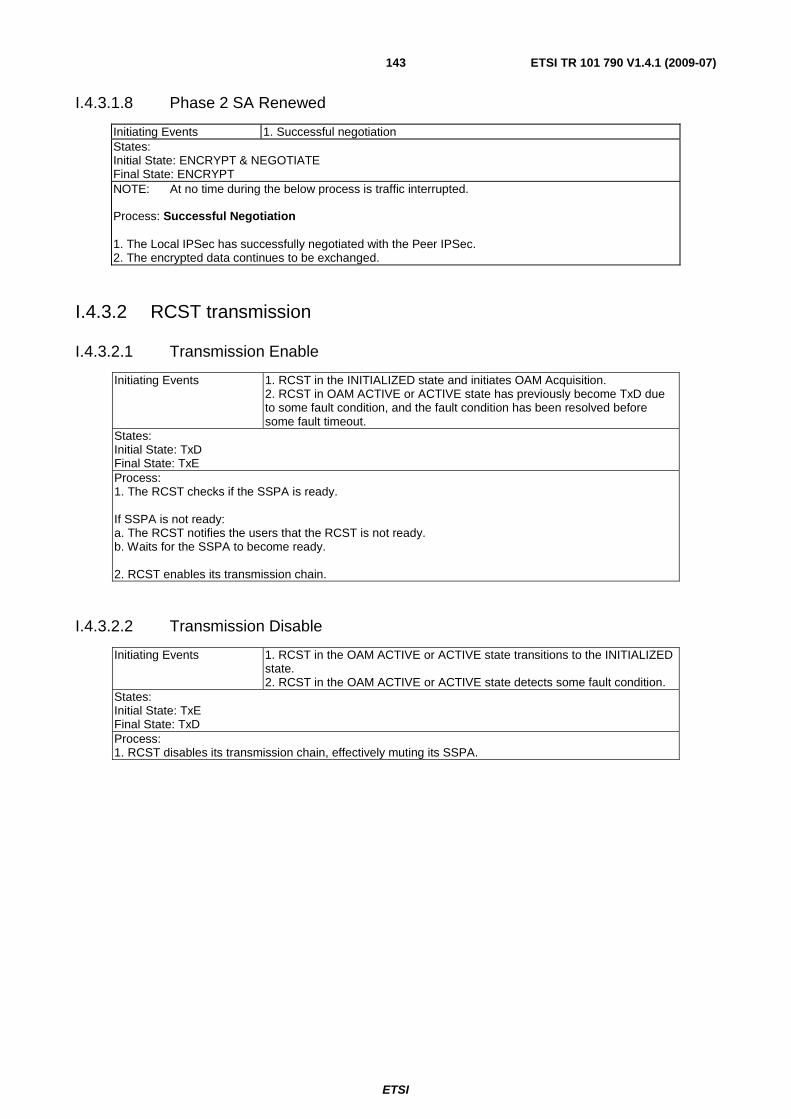
ETSI
ETSI TR 101 790 V1.4.1 (2009-07) 143
I.4.3.1.8 Phase 2 SA Renewed
Initiating Events 1. Successful negotiation States: Initial State: ENCRYPT & NEGOTIATE Final State: ENCRYPT NOTE: At no time during the below process is traffic interrupted. Process: Successful Negotiation 1. The Local IPSec has successfully negotiated with the Peer IPSec. 2. The encrypted data continues to be exchanged.
I.4.3.2 RCST transmission
I.4.3.2.1 Transmission Enable
Initiating Events 1. RCST in the INITIALIZED state and initiates OAM Acquisition. 2. RCST in OAM ACTIVE or ACTIVE state has previously become TxD due to some fault condition, and the fault condition has been resolved before some fault timeout.
States: Initial State: TxD Final State: TxE Process: 1. The RCST checks if the SSPA is ready. If SSPA is not ready: a. The RCST notifies the users that the RCST is not ready. b. Waits for the SSPA to become ready. 2. RCST enables its transmission chain.
I.4.3.2.2 Transmission Disable
Initiating Events 1. RCST in the OAM ACTIVE or ACTIVE state transitions to the INITIALIZED state. 2. RCST in the OAM ACTIVE or ACTIVE state detects some fault condition.
States: Initial State: TxE Final State: TxD Process: 1. RCST disables its transmission chain, effectively muting its SSPA.
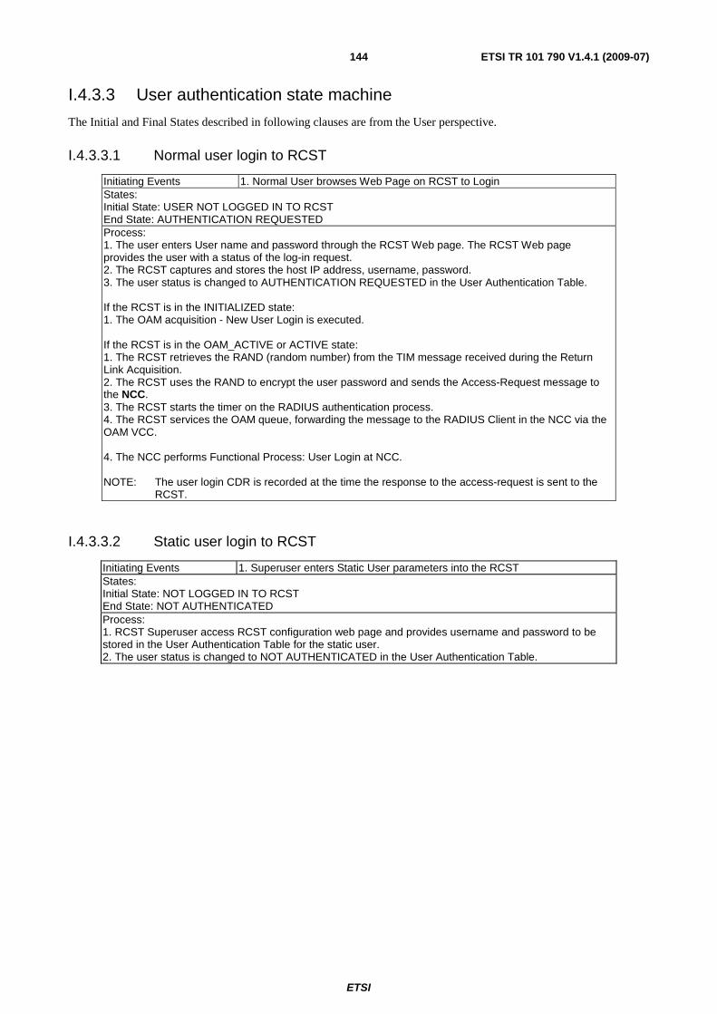
ETSI
ETSI TR 101 790 V1.4.1 (2009-07) 144
I.4.3.3 User authentication state machine
The Initial and Final States described in following clauses are from the User perspective.
I.4.3.3.1 Normal user login to RCST
Initiating Events 1. Normal User browses Web Page on RCST to Login States: Initial State: USER NOT LOGGED IN TO RCST End State: AUTHENTICATION REQUESTED Process: 1. The user enters User name and password through the RCST Web page. The RCST Web page provides the user with a status of the log-in request. 2. The RCST captures and stores the host IP address, username, password. 3. The user status is changed to AUTHENTICATION REQUESTED in the User Authentication Table. If the RCST is in the INITIALIZED state: 1. The OAM acquisition - New User Login is executed. If the RCST is in the OAM_ACTIVE or ACTIVE state: 1. The RCST retrieves the RAND (random number) from the TIM message received during the Return Link Acquisition. 2. The RCST uses the RAND to encrypt the user password and sends the Access-Request message to the NCC. 3. The RCST starts the timer on the RADIUS authentication process. 4. The RCST services the OAM queue, forwarding the message to the RADIUS Client in the NCC via the OAM VCC. 4. The NCC performs Functional Process: User Login at NCC. NOTE: The user login CDR is recorded at the time the response to the access-request is sent to the
RCST.
I.4.3.3.2 Static user login to RCST
Initiating Events 1. Superuser enters Static User parameters into the RCST States: Initial State: NOT LOGGED IN TO RCST End State: NOT AUTHENTICATED Process: 1. RCST Superuser access RCST configuration web page and provides username and password to be stored in the User Authentication Table for the static user. 2. The user status is changed to NOT AUTHENTICATED in the User Authentication Table.
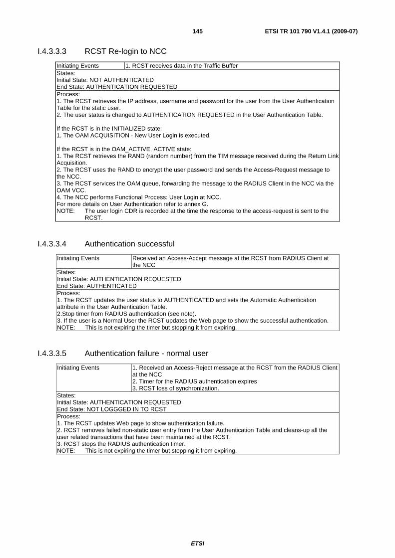
ETSI
ETSI TR 101 790 V1.4.1 (2009-07) 145
I.4.3.3.3 RCST Re-login to NCC
Initiating Events 1. RCST receives data in the Traffic Buffer States: Initial State: NOT AUTHENTICATED End State: AUTHENTICATION REQUESTED Process: 1. The RCST retrieves the IP address, username and password for the user from the User Authentication Table for the static user. 2. The user status is changed to AUTHENTICATION REQUESTED in the User Authentication Table. If the RCST is in the INITIALIZED state: 1. The OAM ACQUISITION - New User Login is executed. If the RCST is in the OAM_ACTIVE, ACTIVE state: 1. The RCST retrieves the RAND (random number) from the TIM message received during the Return Link Acquisition. 2. The RCST uses the RAND to encrypt the user password and sends the Access-Request message to the NCC. 3. The RCST services the OAM queue, forwarding the message to the RADIUS Client in the NCC via the OAM VCC. 4. The NCC performs Functional Process: User Login at NCC. For more details on User Authentication refer to annex G. NOTE: The user login CDR is recorded at the time the response to the access-request is sent to the
RCST.
I.4.3.3.4 Authentication successful
Initiating Events Received an Access-Accept message at the RCST from RADIUS Client at the NCC
States: Initial State: AUTHENTICATION REQUESTED End State: AUTHENTICATED Process: 1. The RCST updates the user status to AUTHENTICATED and sets the Automatic Authentication attribute in the User Authentication Table. 2.Stop timer from RADIUS authentication (see note). 3. If the user is a Normal User the RCST updates the Web page to show the successful authentication. NOTE: This is not expiring the timer but stopping it from expiring.
I.4.3.3.5 Authentication failure - normal user
Initiating Events 1. Received an Access-Reject message at the RCST from the RADIUS Client at the NCC 2. Timer for the RADIUS authentication expires 3. RCST loss of synchronization.
States: Initial State: AUTHENTICATION REQUESTED End State: NOT LOGGGED IN TO RCST Process: 1. The RCST updates Web page to show authentication failure. 2. RCST removes failed non-static user entry from the User Authentication Table and cleans-up all the user related transactions that have been maintained at the RCST. 3. RCST stops the RADIUS authentication timer. NOTE: This is not expiring the timer but stopping it from expiring.
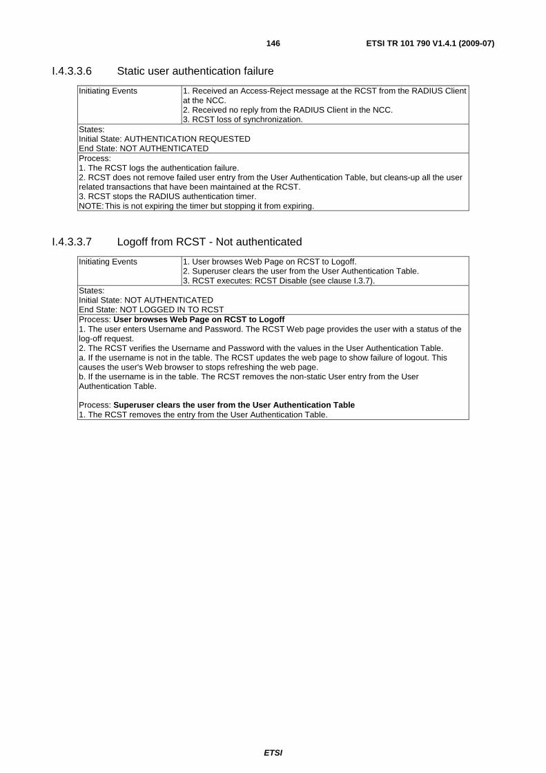
ETSI
ETSI TR 101 790 V1.4.1 (2009-07) 146
I.4.3.3.6 Static user authentication failure
Initiating Events 1. Received an Access-Reject message at the RCST from the RADIUS Client at the NCC. 2. Received no reply from the RADIUS Client in the NCC. 3. RCST loss of synchronization.
States: Initial State: AUTHENTICATION REQUESTED End State: NOT AUTHENTICATED Process: 1. The RCST logs the authentication failure. 2. RCST does not remove failed user entry from the User Authentication Table, but cleans-up all the user related transactions that have been maintained at the RCST. 3. RCST stops the RADIUS authentication timer. NOTE: This is not expiring the timer but stopping it from expiring.
I.4.3.3.7 Logoff from RCST - Not authenticated
Initiating Events 1. User browses Web Page on RCST to Logoff. 2. Superuser clears the user from the User Authentication Table. 3. RCST executes: RCST Disable (see clause I.3.7).
States: Initial State: NOT AUTHENTICATED End State: NOT LOGGED IN TO RCST Process: User browses Web Page on RCST to Logoff 1. The user enters Username and Password. The RCST Web page provides the user with a status of the log-off request. 2. The RCST verifies the Username and Password with the values in the User Authentication Table. a. If the username is not in the table. The RCST updates the web page to show failure of logout. This causes the user's Web browser to stops refreshing the web page. b. If the username is in the table. The RCST removes the non-static User entry from the User Authentication Table. Process: Superuser clears the user from the User Authentication Table 1. The RCST removes the entry from the User Authentication Table.
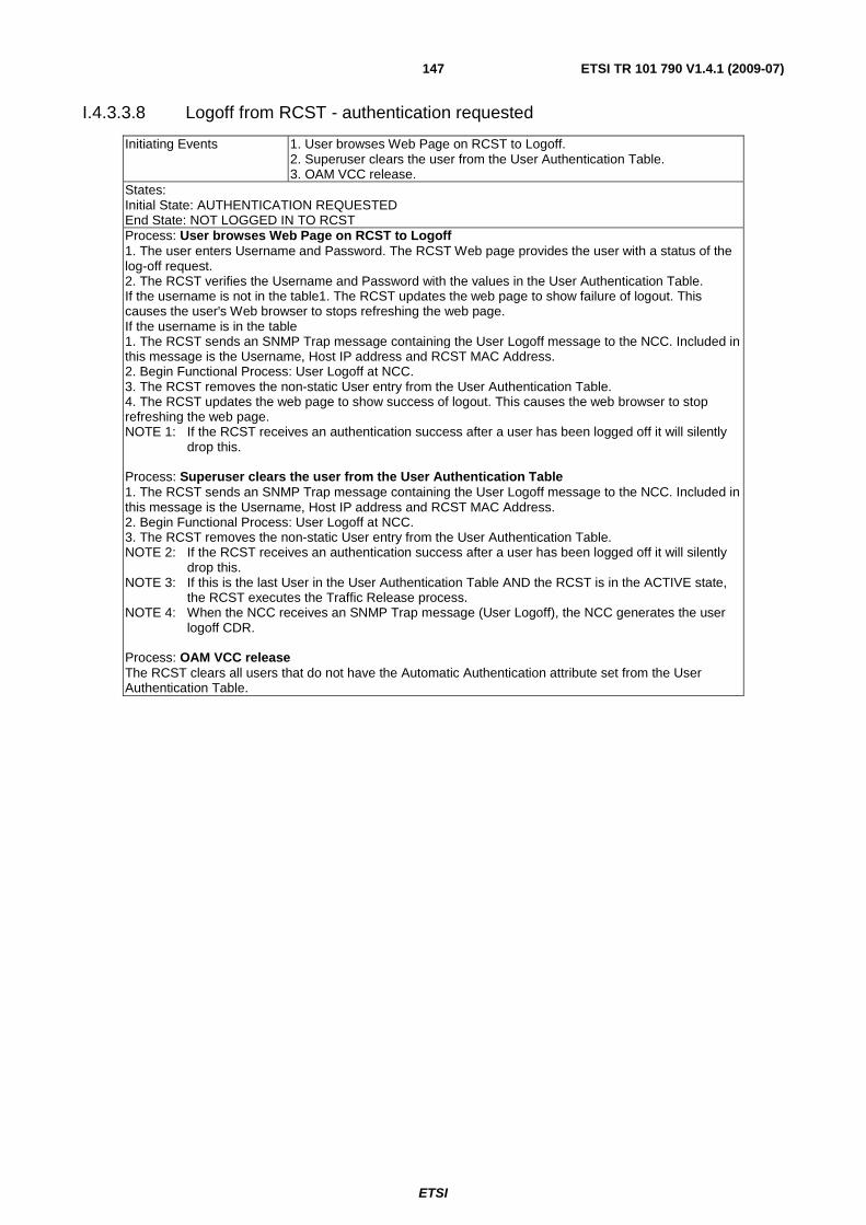
ETSI
ETSI TR 101 790 V1.4.1 (2009-07) 147
I.4.3.3.8 Logoff from RCST - authentication requested
Initiating Events 1. User browses Web Page on RCST to Logoff. 2. Superuser clears the user from the User Authentication Table. 3. OAM VCC release.
States: Initial State: AUTHENTICATION REQUESTED End State: NOT LOGGED IN TO RCST Process: User browses Web Page on RCST to Logoff 1. The user enters Username and Password. The RCST Web page provides the user with a status of the log-off request. 2. The RCST verifies the Username and Password with the values in the User Authentication Table. If the username is not in the table1. The RCST updates the web page to show failure of logout. This causes the user's Web browser to stops refreshing the web page. If the username is in the table 1. The RCST sends an SNMP Trap message containing the User Logoff message to the NCC. Included in this message is the Username, Host IP address and RCST MAC Address. 2. Begin Functional Process: User Logoff at NCC. 3. The RCST removes the non-static User entry from the User Authentication Table. 4. The RCST updates the web page to show success of logout. This causes the web browser to stop refreshing the web page. NOTE 1: If the RCST receives an authentication success after a user has been logged off it will silently
drop this. Process: Superuser clears the user from the User Authentication Table 1. The RCST sends an SNMP Trap message containing the User Logoff message to the NCC. Included in this message is the Username, Host IP address and RCST MAC Address. 2. Begin Functional Process: User Logoff at NCC. 3. The RCST removes the non-static User entry from the User Authentication Table. NOTE 2: If the RCST receives an authentication success after a user has been logged off it will silently
drop this. NOTE 3: If this is the last User in the User Authentication Table AND the RCST is in the ACTIVE state,
the RCST executes the Traffic Release process. NOTE 4: When the NCC receives an SNMP Trap message (User Logoff), the NCC generates the user
logoff CDR. Process: OAM VCC release The RCST clears all users that do not have the Automatic Authentication attribute set from the User Authentication Table.
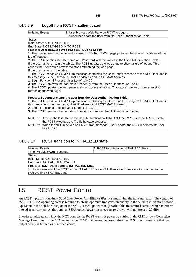
ETSI
ETSI TR 101 790 V1.4.1 (2009-07) 148
I.4.3.3.9 Logoff from RCST - authenticated
Initiating Events 1. User browses Web Page on RCST to Logoff. 2. Superuser clears the user from the User Authentication Table.
States: Initial State: AUTHENTICATED End State: NOT LOGGED IN TO RCST Process: User browses Web Page on RCST to Logoff 1. The user enters Username and Password. The RCST Web page provides the user with a status of the log-off request. 2. The RCST verifies the Username and Password with the values in the User Authentication Table. If the username is not in the table1. The RCST updates the web page to show failure of logout. This causes the user's Web browser to stops refreshing the web page. If the username is in the table: 1. The RCST sends an SNMP Trap message containing the User Logoff message to the NCC. Included in this message is the Username, Host IP address and RCST MAC Address. 2. Begin Functional Process: User Logoff at NCC. 3. The RCST removes the non-static User entry from the User Authentication Table. 4. The RCST updates the web page to show success of logout. This causes the web browser to stop refreshing the web page. Process: Superuser clears the user from the User Authentication Table 1. The RCST sends an SNMP Trap message containing the User Logoff message to the NCC. Included in this message is the Username, Host IP address and RCST MAC Address. 2. Begin Functional Process: User Logoff at NCC. 3. The RCST removes the non-static User entry from the User Authentication Table. NOTE 1: If this is the last User in the User Authentication Table AND the RCST is in the ACTIVE state,
the RCST executes the Traffic Release process. NOTE 2: When the NCC receives an SNMP Trap message (User Logoff), the NCC generates the user
logoff CDR.
I.4.3.3.10 RCST transition to INITIALIZED state
Initiating Events 1. RCST transitions to INITIALIZED State. Time (Min/Max/Avg) (Seconds) States: Initial State: AUTHENTICATED End State: NOT AUTHENTICATED Process: RCST transitions to INITIALIZED State 1. Upon transition of the RCST to the INITIALIZED state all Authenticated Users are transitioned to the NOT AUTHENTICATED state.
I.5 RCST Power Control An RCST typically contains a Solid State Power Amplifier (SSPA) for amplifying the transmit signal. The control of the RCST SSPA operating point is required to obtain optimum transmission quality in the satellite interactive network. Operation in the non-linear region of the SSPA causes spectrum re-growth of the transmitted carrier, which interferes into adjacent carriers. At the nominal SSPA output power the spectrum re-growth will not exceed -20 dBc.
In order to mitigate rain fade the NCC controls the RCST transmit power by entries in the CMT or by a Correction Message Descriptor. If the NCC requests the RCST to increase the power, then the RCST has to take care that the output power is limited as described above.
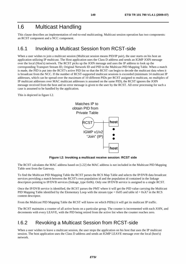
ETSI
ETSI TR 101 790 V1.4.1 (2009-07) 149
I.6 Multicast Handling This clause describes an implementation of end-to-end multicasting. Multicast session operation has two components: an RCST component and a NCC component.
I.6.1 Invoking a Multicast Session from RCST-side When a user wishes to join a multicast session (Multicast session means PID/IP pair), the user starts on his host an application utilizing IP multicast. The Host application uses the Class D address and sends an IGMP JOIN message over the local (Host's) network. The RCST picks up the JOIN message and uses the IP address to look up the corresponding Transport Stream ID, Original Network ID and PID in the Multicast PID Mapping Table. When a match is made, the PID is put into the RCST's active PID list so that the RCST can begin to decode the multicast data when it is broadcast from the NCC. If the number of RCST-supported multicast sessions is exceeded (minimum 14 multicast IP addresses, which can be spread over the maximum of 10 different PIDs per RCST assigned to multicast, no multiplex of IP multicast addresses over MAC multicast addresses is assumed on the same PID), the RCST ignores the JOIN message received from the host and no error message is given to the user by the RCST. All error processing for such a case is assumed to be handled by the application.
This is depicted in figure I.2.
RCST host
host
IGMP v1/v2“Join” (IP)
Matches IP toobtain PID from
Private Table
Figure I.2: Invoking a multicast receive session: RCST side
The RCST calculates the MAC address based on [i.22] the MAC address is not included in the Multicast PID Mapping Table sent from the Gateway.
To find the Multicast PID Mapping Table the RCST parses the RCS Map Table and selects the IP/DVB data broadcast services providing a match between the RCST's own population id and the population id contained in the linkage descriptors pointing to IP/DVB services (linkage_type 0x06). Only one IP/DVB service is assigned to a single RCST.
Once the IP/DVB service is identified, the RCST parses the PMT where it will get the PID value carrying the Multicast PID Mapping Table identified by the Elementary Loop with the stream type = 0x05 and table id = 0xA7 in the RCS content descriptor.
From the Multicast PID Mapping Table the RCST will know on which PID(s) it will get its multicast IP traffic.
The RCST maintains a counter of all active hosts on a particular group. The counter is incremented with each JOIN, and decrements with every LEAVE, with the PID being retired from the active list when the counter reaches zero.
I.6.2 Revoking a Multicast Session from RCST-side When a user wishes to leave a multicast session, the user stops the application on his host that uses the IP multicast session. The host application uses the Class D address and sends an IGMP LEAVE message over the local (host's) network.
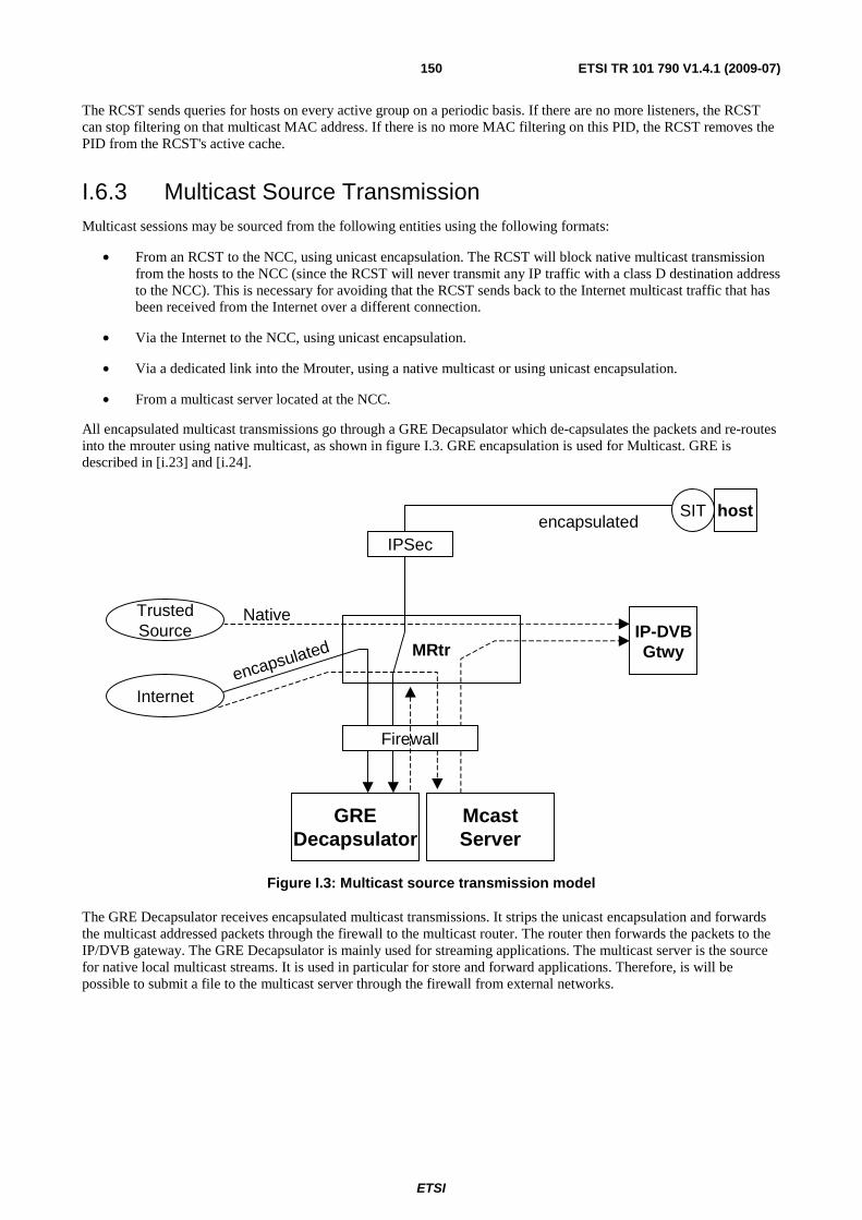
ETSI
ETSI TR 101 790 V1.4.1 (2009-07) 150
The RCST sends queries for hosts on every active group on a periodic basis. If there are no more listeners, the RCST can stop filtering on that multicast MAC address. If there is no more MAC filtering on this PID, the RCST removes the PID from the RCST's active cache.
I.6.3 Multicast Source Transmission Multicast sessions may be sourced from the following entities using the following formats:
• From an RCST to the NCC, using unicast encapsulation. The RCST will block native multicast transmission from the hosts to the NCC (since the RCST will never transmit any IP traffic with a class D destination address to the NCC). This is necessary for avoiding that the RCST sends back to the Internet multicast traffic that has been received from the Internet over a different connection.
• Via the Internet to the NCC, using unicast encapsulation.
• Via a dedicated link into the Mrouter, using a native multicast or using unicast encapsulation.
• From a multicast server located at the NCC.
All encapsulated multicast transmissions go through a GRE Decapsulator which de-capsulates the packets and re-routes into the mrouter using native multicast, as shown in figure I.3. GRE encapsulation is used for Multicast. GRE is described in [i.23] and [i.24].
McastServer
IP-DVBGtwyMRtr
Internetencapsulated
TrustedSource
Native
SIT hostencapsulated
IPSec
GREDecapsulator
Firewall
Figure I.3: Multicast source transmission model
The GRE Decapsulator receives encapsulated multicast transmissions. It strips the unicast encapsulation and forwards the multicast addressed packets through the firewall to the multicast router. The router then forwards the packets to the IP/DVB gateway. The GRE Decapsulator is mainly used for streaming applications. The multicast server is the source for native local multicast streams. It is used in particular for store and forward applications. Therefore, is will be possible to submit a file to the multicast server through the firewall from external networks.

ETSI
ETSI TR 101 790 V1.4.1 (2009-07) 151
Annex J: Example Connection Control Protocol A connection control protocol specification can be found in TS 102 602 [i.46] .
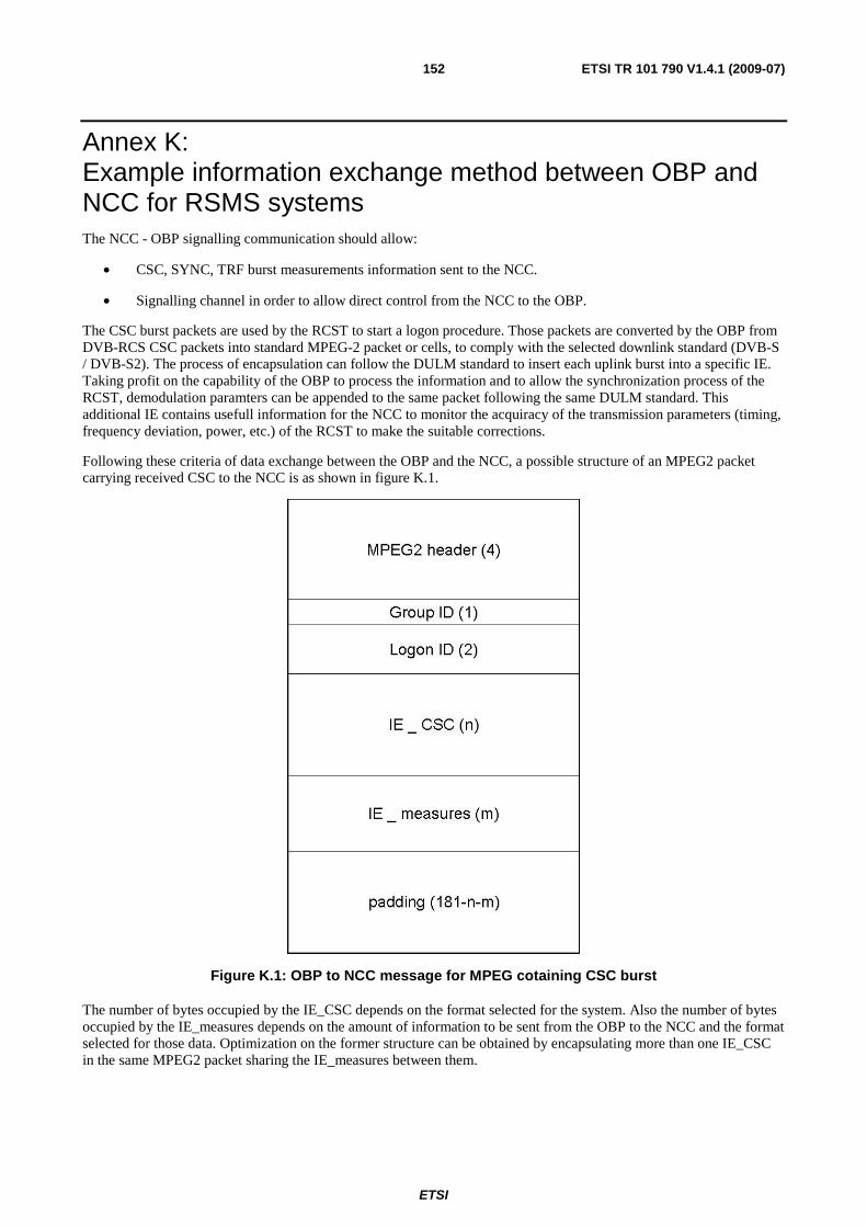
ETSI
ETSI TR 101 790 V1.4.1 (2009-07) 152
Annex K: Example information exchange method between OBP and NCC for RSMS systems The NCC - OBP signalling communication should allow:
• CSC, SYNC, TRF burst measurements information sent to the NCC.
• Signalling channel in order to allow direct control from the NCC to the OBP.
The CSC burst packets are used by the RCST to start a logon procedure. Those packets are converted by the OBP from DVB-RCS CSC packets into standard MPEG-2 packet or cells, to comply with the selected downlink standard (DVB-S / DVB-S2). The process of encapsulation can follow the DULM standard to insert each uplink burst into a specific IE. Taking profit on the capability of the OBP to process the information and to allow the synchronization process of the RCST, demodulation paramters can be appended to the same packet following the same DULM standard. This additional IE contains usefull information for the NCC to monitor the acquiracy of the transmission parameters (timing, frequency deviation, power, etc.) of the RCST to make the suitable corrections.
Following these criteria of data exchange between the OBP and the NCC, a possible structure of an MPEG2 packet carrying received CSC to the NCC is as shown in figure K.1.
Figure K.1: OBP to NCC message for MPEG cotaining CSC burst
The number of bytes occupied by the IE_CSC depends on the format selected for the system. Also the number of bytes occupied by the IE_measures depends on the amount of information to be sent from the OBP to the NCC and the format selected for those data. Optimization on the former structure can be obtained by encapsulating more than one IE_CSC in the same MPEG2 packet sharing the IE_measures between them.
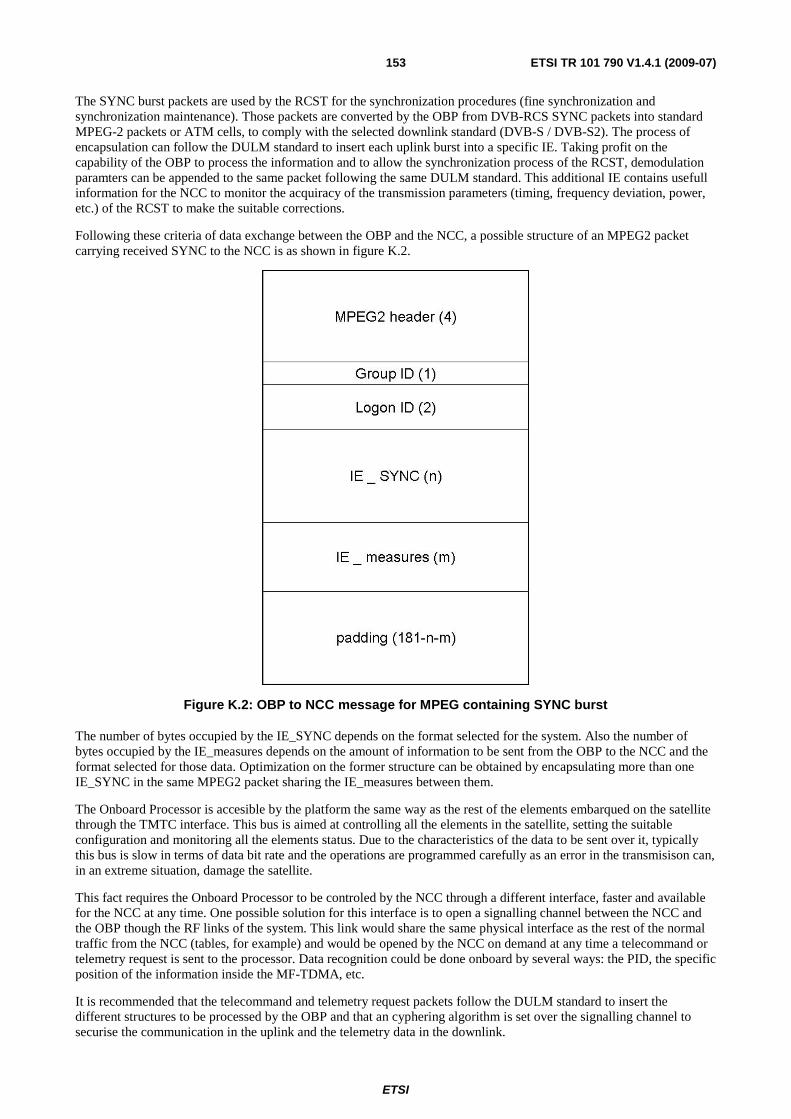
ETSI
ETSI TR 101 790 V1.4.1 (2009-07) 153
The SYNC burst packets are used by the RCST for the synchronization procedures (fine synchronization and synchronization maintenance). Those packets are converted by the OBP from DVB-RCS SYNC packets into standard MPEG-2 packets or ATM cells, to comply with the selected downlink standard (DVB-S / DVB-S2). The process of encapsulation can follow the DULM standard to insert each uplink burst into a specific IE. Taking profit on the capability of the OBP to process the information and to allow the synchronization process of the RCST, demodulation paramters can be appended to the same packet following the same DULM standard. This additional IE contains usefull information for the NCC to monitor the acquiracy of the transmission parameters (timing, frequency deviation, power, etc.) of the RCST to make the suitable corrections.
Following these criteria of data exchange between the OBP and the NCC, a possible structure of an MPEG2 packet carrying received SYNC to the NCC is as shown in figure K.2.
Figure K.2: OBP to NCC message for MPEG containing SYNC burst
The number of bytes occupied by the IE_SYNC depends on the format selected for the system. Also the number of bytes occupied by the IE_measures depends on the amount of information to be sent from the OBP to the NCC and the format selected for those data. Optimization on the former structure can be obtained by encapsulating more than one IE_SYNC in the same MPEG2 packet sharing the IE_measures between them.
The Onboard Processor is accesible by the platform the same way as the rest of the elements embarqued on the satellite through the TMTC interface. This bus is aimed at controlling all the elements in the satellite, setting the suitable configuration and monitoring all the elements status. Due to the characteristics of the data to be sent over it, typically this bus is slow in terms of data bit rate and the operations are programmed carefully as an error in the transmisison can, in an extreme situation, damage the satellite.
This fact requires the Onboard Processor to be controled by the NCC through a different interface, faster and available for the NCC at any time. One possible solution for this interface is to open a signalling channel between the NCC and the OBP though the RF links of the system. This link would share the same physical interface as the rest of the normal traffic from the NCC (tables, for example) and would be opened by the NCC on demand at any time a telecommand or telemetry request is sent to the processor. Data recognition could be done onboard by several ways: the PID, the specific position of the information inside the MF-TDMA, etc.
It is recommended that the telecommand and telemetry request packets follow the DULM standard to insert the different structures to be processed by the OBP and that an cyphering algorithm is set over the signalling channel to securise the communication in the uplink and the telemetry data in the downlink.

ETSI
ETSI TR 101 790 V1.4.1 (2009-07) 154
Direct configuration and monitoring channel can be established between the NCC and all units that can be accessed by the NCC traffic.
For those units that are not processing the NCC traffic directly, an indirect singalling channel is established internally in the OBP. Depending on the internal architecture of the OBP, this indirect signalling channel could use an internal communication bus connecting all the units in the processor or specifically designed architectures. Despite the method used inside the OBP, the requests sent by the NCC to be received by the correct unit and the answers sent by the units to reach the NCC.
ETSI
ETSI TR 101 790 V1.4.1 (2009-07) 155
Annex L: Applicability of DVB-RCS to mobile services
L.1 Introduction This annex provides examples and propositions for the potential use of the mandatory parts of the DVB-RCS standard for mobile applications. Though the mandatory parts of the DVB-RCS standard specifications EN 301 790 [i.2] and the present document are clearly defined for fixed applications, they may also provide answer to some specific mobility requirements. The annex is not written to provide an exhaustive and comprehensive analysis on mobility aspects in DVB-RCS, but rather to provide example conditions and DVB-RCS system parameter ranges where mobile applications can be covered without applying the optional mobile use specific parts of EN 301 790 [i.2].
Guidelines for implementation of the optional mobile use specific parts of EN 301 790 [i.2] can be found in [i.55].
The propositions and guidelines provided below rely on two conditions:
• They focus on the IDU (modem) part of the terminal, assuming that ODUs (in particular antennas) suitable to the required mobility environment and applications (i.e. terrestrial, aeronautical or maritime) are used.
• The air interface (in particular physical layer characteristics) having been defined for a channel approximately equivalent to an Additive White Gaussian Noise (AWGN) channel, only favourable propagation conditions are under consideration. This assumes in particular no multipath and shadowing constraints, presence of line of sight signal, and in worst case conditions, fade degradation remaining limited and compatible with system link budgets.
The annex has been written considering the following assumptions:
• the mobile terminal complies with the DVB-RCS normative document [i.2] and the present document without any enhancement;
• in general, the gateway design reflects current developments and does not include any enhancement specific to mobile services;
• the mobility needs can be covered by a selection or optimization of the operational parameters (most of them corresponding to specific parameter configurations of the NCC/gateway, such as signalling periodicity, loop periodicity, burst guard times, etc.) and system or service parameters (such as channel rates).
One of the objectives of this annex is to present combined ranges of terminal performance and mobile environment characteristics. The specific constraints of the mobile environment (terminal speed, modest size antennas for "communications-on-the-move", frequency spectrum and regulatory constraints) are specifically considered. The applicability of DVB-RCS standard in that context is analyzed in details in clause L.2 and in clause L.3.
In clauses L.4 and L.5, some additional considerations are proposed for the utilization of the DVB-RCS standard in mobile environments. Clause L.4 covers the specific aspects of the mobility management, still in the frame of EN 301 790 [i.2] definition (assuming in particular no modification of the DVB-RCS air interface) but possibly leading to specific enhancements in gateway or terminal implementations. Clause L.5 provides additional considerations related to DVB-RCS mobile services.
L.2 Applicability of DVB-RCS forward and return synchronisation
The application of DVB-RCS to moving terminals implies the consideration of Doppler effects due to terminal motion and the limits where these effects are acceptably handled for safe forward and return synchronization. The effect of Doppler on a DVB-RCS link is already handled in a classical DVB-RCS system, where the satellite motion is considered in the time and frequency synchronization budgets. Depending on the type of application and the type of terminals, the Doppler effect due to the motion of the terminal itself can exceed by far the satellite Doppler.

ETSI
ETSI TR 101 790 V1.4.1 (2009-07) 156
The effects of terminal motion are to be considered in terms of:
• Forward synchronization: limits within which the NCR based synchronization mechanism remains reliable.
• Effect of frequency offset and time drift on forward link physical layer.
• Effect of frequency offset, frequency and timing drift on the return link: this relates to the MF-TDMA demodulator performance. Though not specified in the standard, performances can be defined relying on best practice in gateway receiver implementation.
• Return link time synchronization (acquisition and maintenance).
L.2.1 Doppler shift and time drift Table L.1 gives some typical values in Ku-band for Doppler shift and time drift, for different types of mobile terminals (i.e. with various speed and acceleration). The table provides worst case Doppler shifts, assuming terminal motion towards the satellite and minimum elevation angle (leading to a minimum relative angle θ between the vehicle and the satellite θ=0). The Doppler values due to satellite motion are also included for reference.
Table L.1: Doppler shift in Ku-band for different types of mobile terminals
Type of mobile
terminal (note 1)
Speed
Acceleration (m/s2)
Doppler rate (note 2)
Uplink Doppler
frequency shift
(note 3) (Hz)
Downlink Doppler
frequency shift
(note 4) (Hz)
Time drift
(ns/s)
Uplink frequency
drift (Hz/s)
Downlink frequency
drift (Hz/s)
Pedestrian 5 km/h 1 4,6E-09 67 59 4,6 48 43 Maritime 25 km/h 5 2,3E-08 336 295 23,1 242 213 Vehicular 120 km/h 10 1,1E-07 1 611 1 417 111 483 425 Train 350 km/h 5 3,2E-07 4 699 4 132 324 242 213 Aeronautical 330 m/s 17 1,1E-06 15 950 14 025 1 100 822 723 Satellite 3 m/s 0 1,0E-08 145 128 10 4,8 4,3 NOTE 1: Vehicular: bus, car, truck Aeronautical: < speed of sound Satellite: satellite movement (GSO) assuming satellite motion is versus nadir (reference point) NOTE 2: The maximum Doppler values due to satellite motion are typical for geostationary satellite during main mission
life. The worst case Doppler values (e.g. when satellite mission is extended using inclined orbit satellite) are not considered here.
NOTE 3: Uplink frequency: 14,5 GHz. NOTE 4: Downlink frequency: 12,75 GHz.
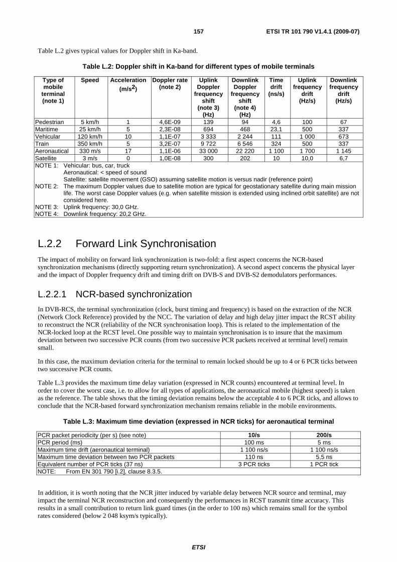
ETSI
ETSI TR 101 790 V1.4.1 (2009-07) 157
Table L.2 gives typical values for Doppler shift in Ka-band.
Table L.2: Doppler shift in Ka-band for different types of mobile terminals
Type of mobile
terminal (note 1)
Speed
Acceleration (m/s2)
Doppler rate (note 2)
Uplink Doppler
frequency shift
(note 3) (Hz)
Downlink Doppler
frequency shift
(note 4) (Hz)
Time drift
(ns/s)
Uplink frequency
drift (Hz/s)
Downlink frequency
drift (Hz/s)
Pedestrian 5 km/h 1 4,6E-09 139 94 4,6 100 67 Maritime 25 km/h 5 2,3E-08 694 468 23,1 500 337 Vehicular 120 km/h 10 1,1E-07 3 333 2 244 111 1 000 673 Train 350 km/h 5 3,2E-07 9 722 6 546 324 500 337 Aeronautical 330 m/s 17 1,1E-06 33 000 22 220 1 100 1 700 1 145 Satellite 3 m/s 0 1,0E-08 300 202 10 10,0 6,7 NOTE 1: Vehicular: bus, car, truck Aeronautical: < speed of sound Satellite: satellite movement (GSO) assuming satellite motion is versus nadir (reference point) NOTE 2: The maximum Doppler values due to satellite motion are typical for geostationary satellite during main mission
life. The worst case Doppler values (e.g. when satellite mission is extended using inclined orbit satellite) are not considered here.
NOTE 3: Uplink frequency: 30,0 GHz. NOTE 4: Downlink frequency: 20,2 GHz.
L.2.2 Forward Link Synchronisation The impact of mobility on forward link synchronization is two-fold: a first aspect concerns the NCR-based synchronization mechanisms (directly supporting return synchronization). A second aspect concerns the physical layer and the impact of Doppler frequency drift and timing drift on DVB-S and DVB-S2 demodulators performances.
L.2.2.1 NCR-based synchronization
In DVB-RCS, the terminal synchronization (clock, burst timing and frequency) is based on the extraction of the NCR (Network Clock Reference) provided by the NCC. The variation of delay and high delay jitter impact the RCST ability to reconstruct the NCR (reliability of the NCR synchronisation loop). This is related to the implementation of the NCR-locked loop at the RCST level. One possible way to maintain synchronisation is to insure that the maximum deviation between two successive PCR counts (from two successive PCR packets received at terminal level) remain small.
In this case, the maximum deviation criteria for the terminal to remain locked should be up to 4 or 6 PCR ticks between two successive PCR counts.
Table L.3 provides the maximum time delay variation (expressed in NCR counts) encountered at terminal level. In order to cover the worst case, i.e. to allow for all types of applications, the aeronautical mobile (highest speed) is taken as the reference. The table shows that the timing deviation remains below the acceptable 4 to 6 PCR ticks, and allows to conclude that the NCR-based forward synchronization mechanism remains reliable in the mobile environments.
Table L.3: Maximum time deviation (expressed in NCR ticks) for aeronautical terminal
PCR packet periodicity (per s) (see note) 10/s 200/s PCR period (ms) 100 ms 5 ms Maximum time drift (aeronautical terminal) 1 100 ns/s 1 100 ns/s Maximum time deviation between two PCR packets 110 ns 5,5 ns Equivalent number of PCR ticks (37 ns) 3 PCR ticks 1 PCR tick NOTE: From EN 301 790 [i.2], clause 8.3.5.
In addition, it is worth noting that the NCR jitter induced by variable delay between NCR source and terminal, may impact the terminal NCR reconstruction and consequently the performances in RCST transmit time accuracy. This results in a small contribution to return link guard times (in the order to 100 ns) which remains small for the symbol rates considered (below 2 048 ksym/s typically).
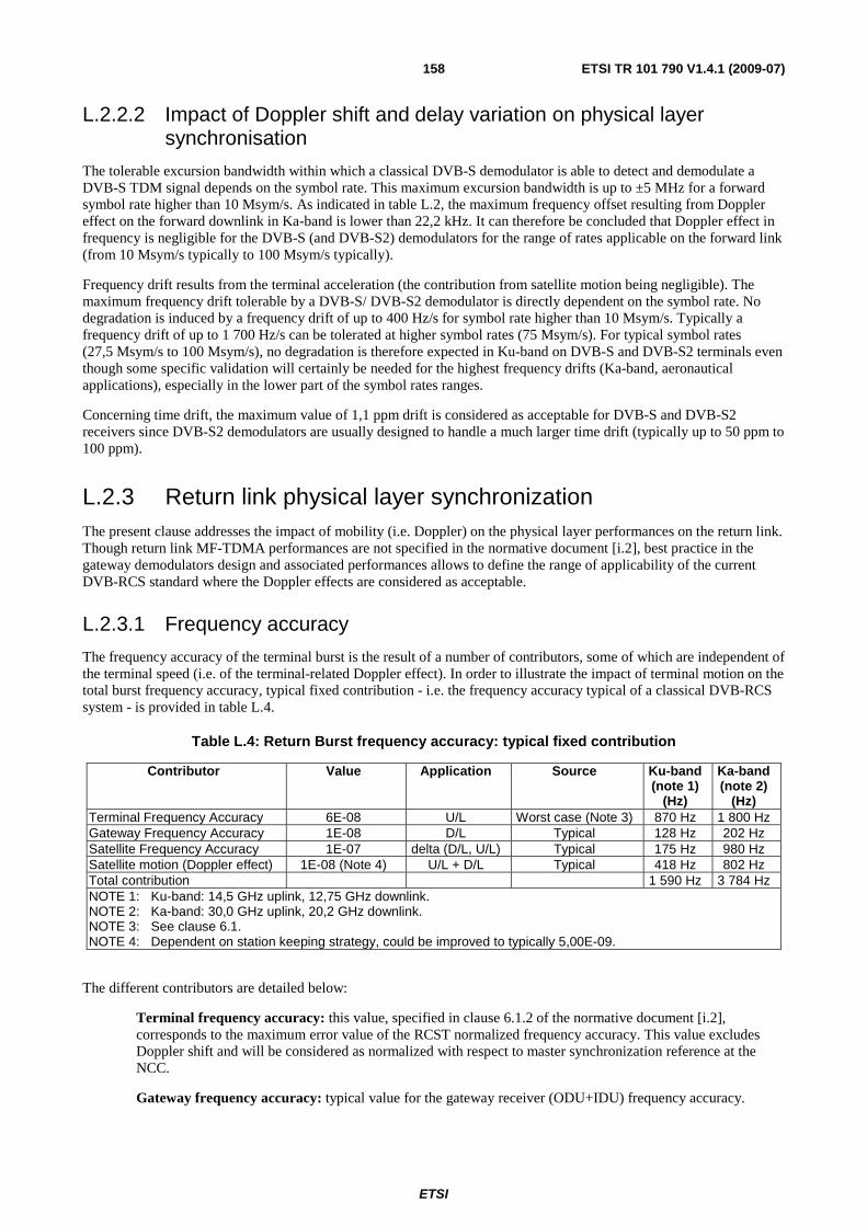
ETSI
ETSI TR 101 790 V1.4.1 (2009-07) 158
L.2.2.2 Impact of Doppler shift and delay variation on physical layer synchronisation
The tolerable excursion bandwidth within which a classical DVB-S demodulator is able to detect and demodulate a DVB-S TDM signal depends on the symbol rate. This maximum excursion bandwidth is up to ±5 MHz for a forward symbol rate higher than 10 Msym/s. As indicated in table L.2, the maximum frequency offset resulting from Doppler effect on the forward downlink in Ka-band is lower than 22,2 kHz. It can therefore be concluded that Doppler effect in frequency is negligible for the DVB-S (and DVB-S2) demodulators for the range of rates applicable on the forward link (from 10 Msym/s typically to 100 Msym/s typically).
Frequency drift results from the terminal acceleration (the contribution from satellite motion being negligible). The maximum frequency drift tolerable by a DVB-S/ DVB-S2 demodulator is directly dependent on the symbol rate. No degradation is induced by a frequency drift of up to 400 Hz/s for symbol rate higher than 10 Msym/s. Typically a frequency drift of up to 1 700 Hz/s can be tolerated at higher symbol rates (75 Msym/s). For typical symbol rates (27,5 Msym/s to 100 Msym/s), no degradation is therefore expected in Ku-band on DVB-S and DVB-S2 terminals even though some specific validation will certainly be needed for the highest frequency drifts (Ka-band, aeronautical applications), especially in the lower part of the symbol rates ranges.
Concerning time drift, the maximum value of 1,1 ppm drift is considered as acceptable for DVB-S and DVB-S2 receivers since DVB-S2 demodulators are usually designed to handle a much larger time drift (typically up to 50 ppm to 100 ppm).
L.2.3 Return link physical layer synchronization The present clause addresses the impact of mobility (i.e. Doppler) on the physical layer performances on the return link. Though return link MF-TDMA performances are not specified in the normative document [i.2], best practice in the gateway demodulators design and associated performances allows to define the range of applicability of the current DVB-RCS standard where the Doppler effects are considered as acceptable.
L.2.3.1 Frequency accuracy
The frequency accuracy of the terminal burst is the result of a number of contributors, some of which are independent of the terminal speed (i.e. of the terminal-related Doppler effect). In order to illustrate the impact of terminal motion on the total burst frequency accuracy, typical fixed contribution - i.e. the frequency accuracy typical of a classical DVB-RCS system - is provided in table L.4.
Table L.4: Return Burst frequency accuracy: typical fixed contribution
Contributor Value Application Source Ku-band (note 1)
(Hz)
Ka-band (note 2)
(Hz) Terminal Frequency Accuracy 6E-08 U/L Worst case (Note 3) 870 Hz 1 800 Hz Gateway Frequency Accuracy 1E-08 D/L Typical 128 Hz 202 Hz Satellite Frequency Accuracy 1E-07 delta (D/L, U/L) Typical 175 Hz 980 Hz Satellite motion (Doppler effect) 1E-08 (Note 4) U/L + D/L Typical 418 Hz 802 Hz Total contribution 1 590 Hz 3 784 Hz NOTE 1: Ku-band: 14,5 GHz uplink, 12,75 GHz downlink. NOTE 2: Ka-band: 30,0 GHz uplink, 20,2 GHz downlink. NOTE 3: See clause 6.1. NOTE 4: Dependent on station keeping strategy, could be improved to typically 5,00E-09.
The different contributors are detailed below:
Terminal frequency accuracy: this value, specified in clause 6.1.2 of the normative document [i.2], corresponds to the maximum error value of the RCST normalized frequency accuracy. This value excludes Doppler shift and will be considered as normalized with respect to master synchronization reference at the NCC.
Gateway frequency accuracy: typical value for the gateway receiver (ODU+IDU) frequency accuracy.
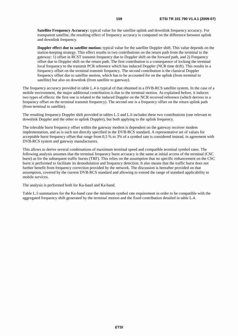
ETSI
ETSI TR 101 790 V1.4.1 (2009-07) 159
Satellite Frequency Accuracy: typical value for the satellite uplink and downlink frequency accuracy. For transparent satellite, the resulting effect of frequency accuracy is computed on the difference between uplink and downlink frequency.
Doppler effect due to satellite motion: typical value for the satellite Doppler shift. This value depends on the station-keeping strategy. This effect results in two contributions on the return path from the terminal to the gateway: 1) offset in RCST transmit frequency due to Doppler shift on the forward path, and 2) Frequency offset due to Doppler shift on the return path. The first contribution is a consequence of locking the terminal local frequency to the transmit PCR reference which has induced Doppler (NCR time drift). This results in a frequency offset on the terminal transmit frequency. The second contribution is the classical Doppler frequency offset due to satellite motion, which has to be accounted for on the uplink (from terminal to satellite) but also on downlink (from satellite to gateway).
The frequency accuracy provided in table L.4 is typical of that obtained in a DVB-RCS satellite system. In the case of a mobile environment, the major additional contribution is due to the terminal motion. As explained before, it induces two types of effects: the first one is related to the induced Doppler on the NCR received reference (which derives in a frequency offset on the terminal transmit frequency). The second one is a frequency offset on the return uplink path (from terminal to satellite).
The resulting frequency Doppler shift provided in tables L.5 and L.6 includes these two contributions (one relevant to downlink Doppler and the other to uplink Doppler), but both applying to the uplink frequency.
The tolerable burst frequency offset within the gateway modem is dependent on the gateway receiver modem implementation, and as is such not directly specified in the DVB-RCS standard. A representative set of values for acceptable burst frequency offset that range from 0,5 % to 3% of a symbol rate is considered instead, in agreement with DVB-RCS system and gateway manufacturers.
This allows to derive several combinations of maximum terminal speed and compatible terminal symbol rates. The following analysis assumes that the terminal frequency burst accuracy is the same at initial access of the terminal (CSC burst) as for the subsequent traffic bursts (TRF). This relies on the assumption that no specific enhancement on the CSC burst is performed to facilitate its demodulation and frequency detection. It also means that the traffic burst does not further benefit from frequency correction provided by the network. The discussion is hereafter provided on that assumption, covered by the current DVB-RCS standard and allowing to extend the range of standard applicability to mobile services.
The analysis is performed both for Ku-band and Ka-band.
Table L.5 summarizes for the Ku-band case the minimum symbol rate requirement in order to be compatible with the aggregated frequency shift generated by the terminal motion and the fixed contribution detailed in table L.4.
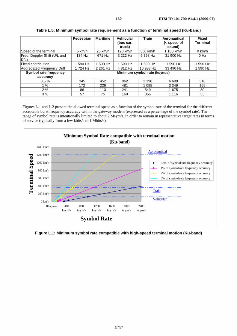
ETSI
ETSI TR 101 790 V1.4.1 (2009-07) 160
Table L.5: Minimum symbol rate requirement as a function of terminal speed (Ku-band)
Pedestrian Maritime Vehicular (bus car,
truck)
Train Aeronautical (< speed of
sound)
Fixed Terminal
Speed of the terminal 5 km/h 25 km/h 120 km/h 350 km/h 1 188 km/h 0 km/h Freq. Doppler Shift (U/L and D/L)
134 Hz 671 Hz 3 222 Hz 9 398 Hz 31 900 Hz 0 Hz
Fixed contribution 1 590 Hz 1 590 Hz 1 590 Hz 1 590 Hz 1 590 Hz 1 590 Hz Aggregated Frequency Drift 1 724 Hz 2 261 Hz 4 812 Hz 10 988 Hz 33 490 Hz 1 590 Hz
Symbol rate frequency accuracy
Minimum symbol rate (ksym/s)
0,5 % 345 452 962 2 198 6 698 318 1 % 172 226 481 1 099 3 349 159 2 % 86 113 241 549 1 675 80 3 % 57 75 160 366 1 116 53
Figures L.1 and L.2 present the allowed terminal speed as a function of the symbol rate of the terminal for the different acceptable burst frequency accuracy within the gateway modem (expressed as a percentage of the symbol rate). The range of symbol rate is intentionally limited to about 2 Msym/s, in order to remain in representative target rates in terms of service (typically from a few kbits/s to 1 Mbits/s).
Minimum Symbol Rate compatible with terminal motion (Ku-band)
0 km/h
200 km/h
400 km/h
600 km/h
800 km/h
1000 km/h
1200 km/h
1400 km/h
0 ksym/s 400ksym/s
800ksym/s
1200ksym/s
1600ksym/s
2000ksym/s
2400ksym/s
Symbol Rate
Ter
min
al S
peed
0.5% of symbol rate frequency accuracy
1% of symbol rate frequency accuracy
2% of symbol rate frequency accuracy
3% of symbol rate frequency accuracy
Vehicular
Aeronautical
Train
Figure L.1: Minimum symbol rate compatible with high-speed terminal motion (Ku-band)
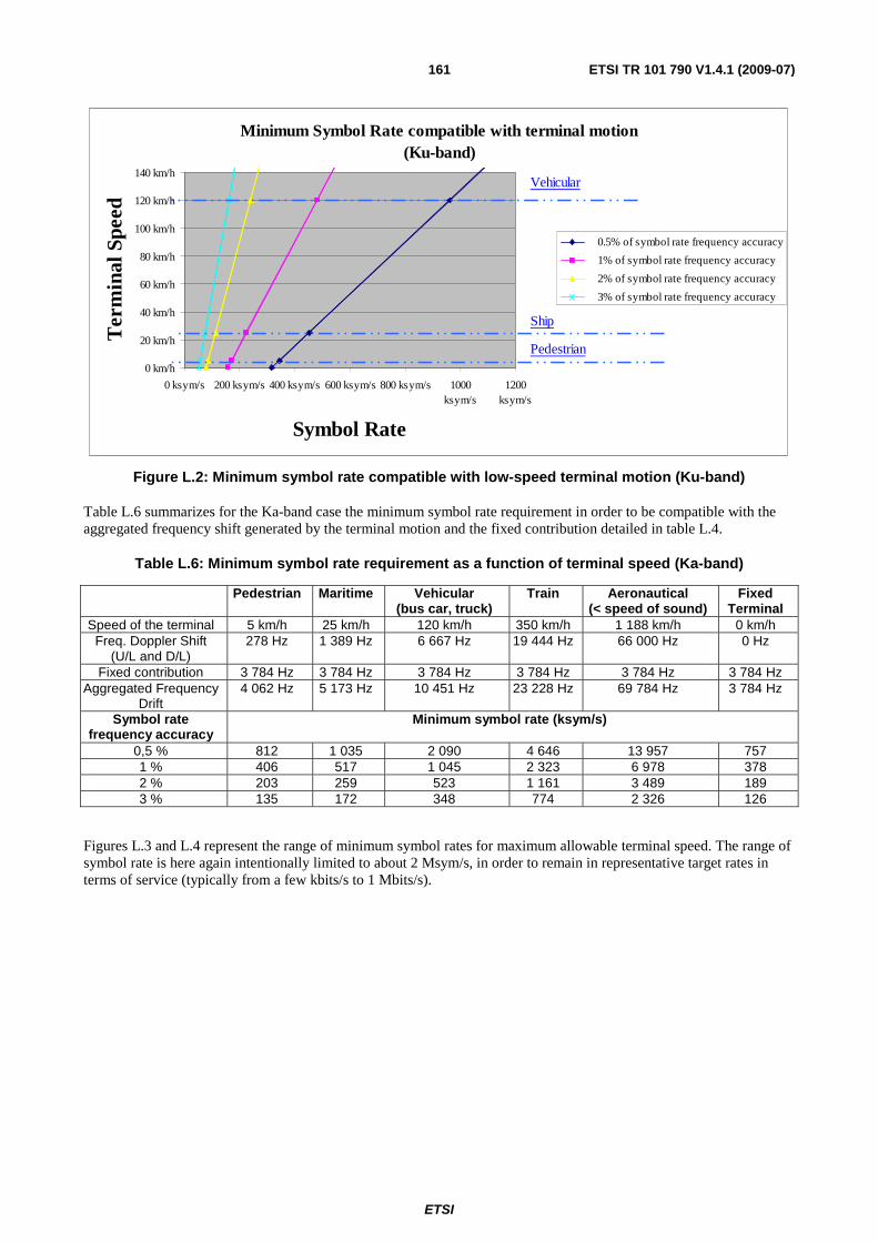
ETSI
ETSI TR 101 790 V1.4.1 (2009-07) 161
Minimum Symbol Rate compatible with terminal motion(Ku-band)
0 km/h
20 km/h
40 km/h
60 km/h
80 km/h
100 km/h
120 km/h
140 km/h
0 ksym/s 200 ksym/s 400 ksym/s 600 ksym/s 800 ksym/s 1000ksym/s
1200ksym/s
Symbol Rate
Ter
min
al S
peed
0.5% of symbol rate frequency accuracy
1% of symbol rate frequency accuracy
2% of symbol rate frequency accuracy
3% of symbol rate frequency accuracy
Vehicular
Ship
Pedestrian
Figure L.2: Minimum symbol rate compatible with low-speed terminal motion (Ku-band)
Table L.6 summarizes for the Ka-band case the minimum symbol rate requirement in order to be compatible with the aggregated frequency shift generated by the terminal motion and the fixed contribution detailed in table L.4.
Table L.6: Minimum symbol rate requirement as a function of terminal speed (Ka-band)
Pedestrian Maritime Vehicular (bus car, truck)
Train Aeronautical (< speed of sound)
Fixed Terminal
Speed of the terminal 5 km/h 25 km/h 120 km/h 350 km/h 1 188 km/h 0 km/h Freq. Doppler Shift
(U/L and D/L) 278 Hz 1 389 Hz 6 667 Hz 19 444 Hz 66 000 Hz 0 Hz
Fixed contribution 3 784 Hz 3 784 Hz 3 784 Hz 3 784 Hz 3 784 Hz 3 784 Hz Aggregated Frequency
Drift 4 062 Hz 5 173 Hz 10 451 Hz 23 228 Hz 69 784 Hz 3 784 Hz
Symbol rate frequency accuracy
Minimum symbol rate (ksym/s)
0,5 % 812 1 035 2 090 4 646 13 957 757 1 % 406 517 1 045 2 323 6 978 378 2 % 203 259 523 1 161 3 489 189 3 % 135 172 348 774 2 326 126
Figures L.3 and L.4 represent the range of minimum symbol rates for maximum allowable terminal speed. The range of symbol rate is here again intentionally limited to about 2 Msym/s, in order to remain in representative target rates in terms of service (typically from a few kbits/s to 1 Mbits/s).
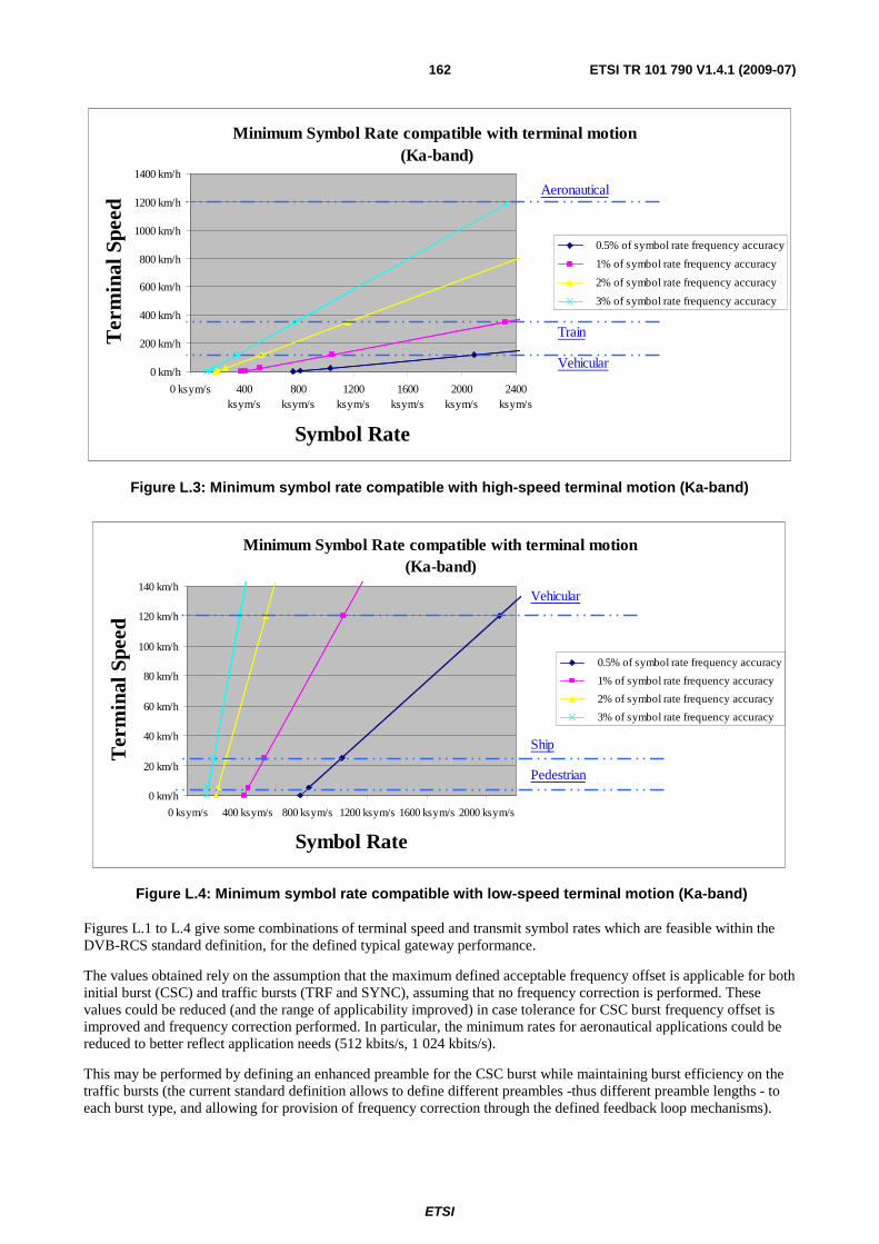
ETSI
ETSI TR 101 790 V1.4.1 (2009-07) 162
Minimum Symbol Rate compatible with terminal motion (Ka-band)
0 km/h
200 km/h
400 km/h
600 km/h
800 km/h
1000 km/h
1200 km/h
1400 km/h
0 ksym/s 400ksym/s
800ksym/s
1200ksym/s
1600ksym/s
2000ksym/s
2400ksym/s
Symbol Rate
Ter
min
al S
peed
0.5% of symbol rate frequency accuracy
1% of symbol rate frequency accuracy
2% of symbol rate frequency accuracy
3% of symbol rate frequency accuracy
Vehicular
Aeronautical
Train
Figure L.3: Minimum symbol rate compatible with high-speed terminal motion (Ka-band)
Minimum Symbol Rate compatible with terminal motion(Ka-band)
0 km/h
20 km/h
40 km/h
60 km/h
80 km/h
100 km/h
120 km/h
140 km/h
0 ksym/s 400 ksym/s 800 ksym/s 1200 ksym/s 1600 ksym/s 2000 ksym/s
Symbol Rate
Ter
min
al S
peed
0.5% of symbol rate frequency accuracy
1% of symbol rate frequency accuracy
2% of symbol rate frequency accuracy
3% of symbol rate frequency accuracy
Vehicular
Ship
Pedestrian
Figure L.4: Minimum symbol rate compatible with low-speed terminal motion (Ka-band)
Figures L.1 to L.4 give some combinations of terminal speed and transmit symbol rates which are feasible within the DVB-RCS standard definition, for the defined typical gateway performance.
The values obtained rely on the assumption that the maximum defined acceptable frequency offset is applicable for both initial burst (CSC) and traffic bursts (TRF and SYNC), assuming that no frequency correction is performed. These values could be reduced (and the range of applicability improved) in case tolerance for CSC burst frequency offset is improved and frequency correction performed. In particular, the minimum rates for aeronautical applications could be reduced to better reflect application needs (512 kbits/s, 1 024 kbits/s).
This may be performed by defining an enhanced preamble for the CSC burst while maintaining burst efficiency on the traffic bursts (the current standard definition allows to define different preambles -thus different preamble lengths - to each burst type, and allowing for provision of frequency correction through the defined feedback loop mechanisms).
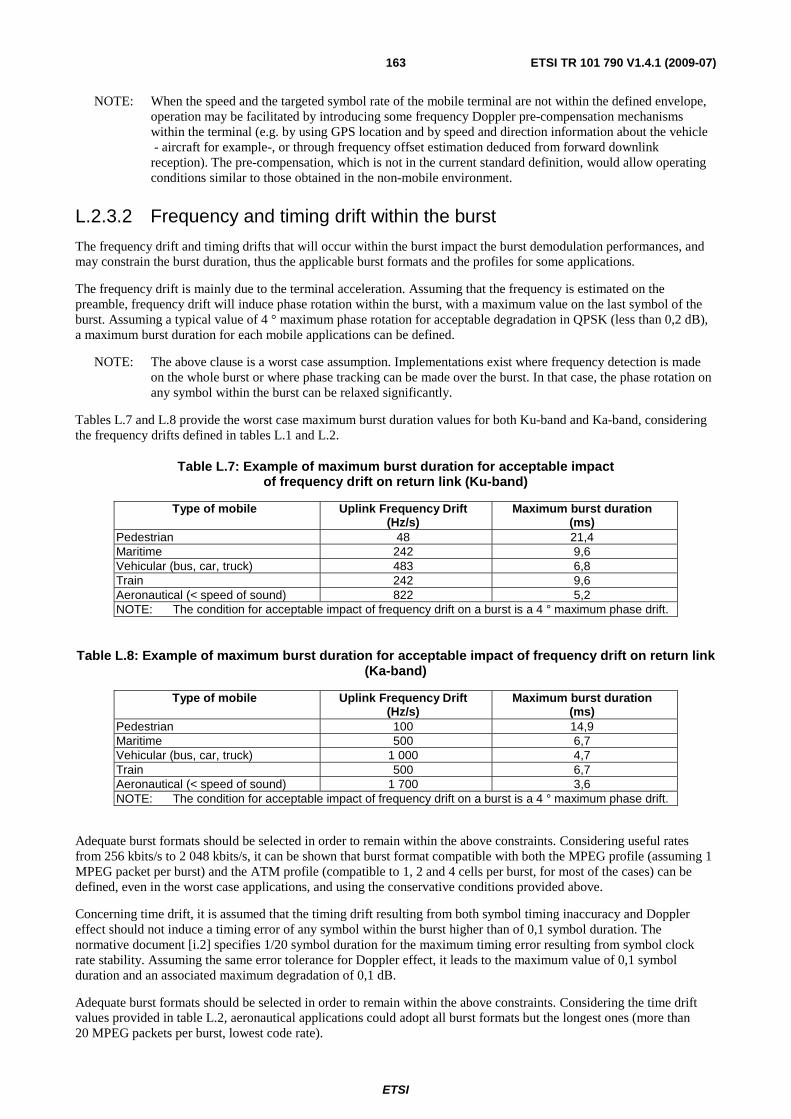
ETSI
ETSI TR 101 790 V1.4.1 (2009-07) 163
NOTE: When the speed and the targeted symbol rate of the mobile terminal are not within the defined envelope, operation may be facilitated by introducing some frequency Doppler pre-compensation mechanisms within the terminal (e.g. by using GPS location and by speed and direction information about the vehicle - aircraft for example-, or through frequency offset estimation deduced from forward downlink reception). The pre-compensation, which is not in the current standard definition, would allow operating conditions similar to those obtained in the non-mobile environment.
L.2.3.2 Frequency and timing drift within the burst
The frequency drift and timing drifts that will occur within the burst impact the burst demodulation performances, and may constrain the burst duration, thus the applicable burst formats and the profiles for some applications.
The frequency drift is mainly due to the terminal acceleration. Assuming that the frequency is estimated on the preamble, frequency drift will induce phase rotation within the burst, with a maximum value on the last symbol of the burst. Assuming a typical value of 4 ° maximum phase rotation for acceptable degradation in QPSK (less than 0,2 dB), a maximum burst duration for each mobile applications can be defined.
NOTE: The above clause is a worst case assumption. Implementations exist where frequency detection is made on the whole burst or where phase tracking can be made over the burst. In that case, the phase rotation on any symbol within the burst can be relaxed significantly.
Tables L.7 and L.8 provide the worst case maximum burst duration values for both Ku-band and Ka-band, considering the frequency drifts defined in tables L.1 and L.2.
Table L.7: Example of maximum burst duration for acceptable impact of frequency drift on return link (Ku-band)
Type of mobile Uplink Frequency Drift (Hz/s)
Maximum burst duration (ms)
Pedestrian 48 21,4 Maritime 242 9,6 Vehicular (bus, car, truck) 483 6,8 Train 242 9,6 Aeronautical (< speed of sound) 822 5,2 NOTE: The condition for acceptable impact of frequency drift on a burst is a 4 ° maximum phase drift.
Table L.8: Example of maximum burst duration for acceptable impact of frequency drift on return link (Ka-band)
Type of mobile Uplink Frequency Drift (Hz/s)
Maximum burst duration (ms)
Pedestrian 100 14,9 Maritime 500 6,7 Vehicular (bus, car, truck) 1 000 4,7 Train 500 6,7 Aeronautical (< speed of sound) 1 700 3,6 NOTE: The condition for acceptable impact of frequency drift on a burst is a 4 ° maximum phase drift.
Adequate burst formats should be selected in order to remain within the above constraints. Considering useful rates from 256 kbits/s to 2 048 kbits/s, it can be shown that burst format compatible with both the MPEG profile (assuming 1 MPEG packet per burst) and the ATM profile (compatible to 1, 2 and 4 cells per burst, for most of the cases) can be defined, even in the worst case applications, and using the conservative conditions provided above.
Concerning time drift, it is assumed that the timing drift resulting from both symbol timing inaccuracy and Doppler effect should not induce a timing error of any symbol within the burst higher than of 0,1 symbol duration. The normative document [i.2] specifies 1/20 symbol duration for the maximum timing error resulting from symbol clock rate stability. Assuming the same error tolerance for Doppler effect, it leads to the maximum value of 0,1 symbol duration and an associated maximum degradation of 0,1 dB.
Adequate burst formats should be selected in order to remain within the above constraints. Considering the time drift values provided in table L.2, aeronautical applications could adopt all burst formats but the longest ones (more than 20 MPEG packets per burst, lowest code rate).
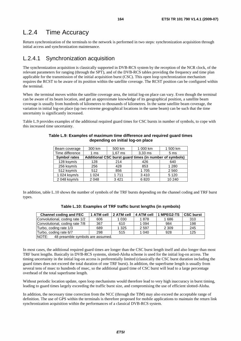
ETSI
ETSI TR 101 790 V1.4.1 (2009-07) 164
L.2.4 Time Accuracy Return synchronization of the terminals to the network is performed in two steps: synchronization acquisition through initial access and synchronization maintenance.
L.2.4.1 Synchronization acquisition
The synchronization acquisition is classically supported in DVB-RCS system by the reception of the NCR clock, of the relevant parameters for ranging (through the SPT), and of the DVB-RCS tables providing the frequency and time plan applicable for the transmission of the initial acquisition burst (CSC). This open loop synchronization mechanism requires the RCST to be aware of its position within the satellite coverage. The RCST position can be configured within the terminal.
When the terminal moves within the satellite coverage area, the initial log-on place can vary. Even though the terminal can be aware of its beam location, and get an approximate knowledge of its geographical position, a satellite beam coverage is usually from hundreds of kilometres to thousands of kilometres. In the same satellite beam coverage, the variation in initial log-on place (up two extreme geographical locations in the same beam) can be such that the time uncertainty is significantly increased.
Table L.9 provides examples of the additional required guard times for CSC bursts in number of symbols, to cope with this increased time uncertainty.
Table L.9: Examples of maximum time difference and required guard times depending on initial log-on place
Beam coverage 300 km 500 km 1 000 km 1 500 km Time difference 1 ms 1,67 ms 3,33 ms 5 ms Symbol rates Additional CSC burst guard times (in number of symbols)
128 ksym/s 128 214 426 640 256 ksym/s 256 428 853 1 280 512 ksym/s 512 856 1 705 2 560
1 024 ksym/s 1 024 1 711 3 410 5 120 2 048 ksym/s 2 048 3 421 6 820 10 240
In addition, table L.10 shows the number of symbols of the TRF bursts depending on the channel coding and TRF burst types.
Table L.10: Examples of TRF traffic burst lengths (in symbols)
Channel coding and FEC 1 ATM cell 2 ATM cell 4 ATM cell 1 MPEG2-TS CSC burst Convolutional, coding rate 1/2 606 1 030 1 878 1 686 310 Convolutional, coding rate 7/8 367 610 1 094 984 198 Turbo, coding rate 1/3 689 1 325 2 597 2 309 245 Turbo, coding rate 6/7 298 515 1 040 928 125 NOTE: 48 preamble symbols are assumed.
In most cases, the additional required guard times are longer than the CSC burst length itself and also longer than most TRF burst lengths. Basically in DVB-RCS systems, slotted-Aloha scheme is used for the initial log-on access. The timing uncertainty in the initial log-on access is preferentially limited (classically the CSC burst duration including the guard times does not exceed the total duration of one TRF burst). In addition, the superframe length is usually from several tens of msec to hundreds of msec, so the additional guard time of CSC burst will lead to a large percentage overhead of the total superframe length.
Without periodic location update, open loop mechanisms would therefore lead to very high inaccuracy in burst timing, leading to guard times largely exceeding the traffic burst size, and compromising the use of efficient slotted-Aloha.
In addition, the necessary time correction from the NCC (through the TIM) may also exceed the acceptable range of definition. The use of GPS within the terminals is therefore proposed for mobile applications to maintain the return link synchronization acquisition within the performances of a classical DVB-RCS system.

ETSI
ETSI TR 101 790 V1.4.1 (2009-07) 165
L.2.4.2 Synchronization maintenance
Time accuracy depends on the link control parameters dimensioning and is therefore related to system specific implementations rather than terminal implementation ranges.
Timing drift affects the performance of the synchronization maintenance loop, impacting in particular the dimensioning of the guard times or the periodicity of the loop. Since those parameters are usually defined to meet specific system requirements, we can not, strictly speaking, express the effect of mobility in terms of additional guard times or SYNC period frequency, as each mobile system will be specific.
The impact of terminal motion can, however, be illustrated in terms of additional guard times, assuming that the other parameters (in particular loop periodicity) will remain the same. The values given in table L.11 are absolute values (in µs), but the impact in terms of equivalent symbol rate (hence burst format) can be easily derived for a given terminal symbol rate.
As an illustration, table L.12 provides the minimum guard times extension, when considering the minimum symbol rate applicable to each terminal type (assuming a maximum frequency offset of 3% of the symbol rate). The table also shows the percentage of additional guard time for typical burst length (one single ATM burst format, 1/2 rate coding). Obviously, the guard time overhead will increase proportionally to the symbol rate .
It is believed that though guard times should be slightly extended or the periodicity of the loop enhanced, this can be accommodated within the current DVB-RCS standard.
Table L.11: Effect of mobility on synchronization maintenance: Maximum time drift for different SYNC periods.
Examples of SYNC period (note 1) (ms) 848 (note 2)
1 400 (note 3)
12 000 (note 4)
Terminal type Time drift during SYNC period including round trip delay (µs) Pedestrian 0,01 0,02 0,12 Maritime 0,06 0,09 0,58 Vehicular (bus, car, truck) 0,30 0,43 2,78 Train 0,89 1,25 8,12 Aeronautical (< speed of sound) 3,02 4,23 27,55 NOTE 1: The examples assume that the periodicity of timing advance correction messages is equal to
SYNC periodicity. NOTE 2: 32 frames, see clause 6.7.1.1. NOTE 3: High activity terminals, see clause 6.7.1.2. NOTE 4: Low activity terminals, see clause 6.7.1.2.
Table L.12: Minimum additional guard times and overheads for each terminal type (assuming minimum symbol rate)
Pedestrian Maritime Vehicular (bus car,
truck)
Train Aeronautical (< speed of
sound) Minimum symbol rate for 3 % Rs frequency offset (ksym/s)
57 75 160 366 1 116
Symbol duration (in µs) 17,4 13,3 6,2 2,7 0,9 Additional guard time (in symbols) 0,0007 0,005 0,05 0,3 3,4 Guard time overhead (note) 0,00 % 0,00 % 0,01 % 0,08 % 0,79 % NOTE: 1 ATM cell burst format.
L.2.5 DVB-RCS synchronisation in mobile environments: Examples
This clause provides examples of ranges and rates for the assumptions in terms of Doppler and system parameters ranges.
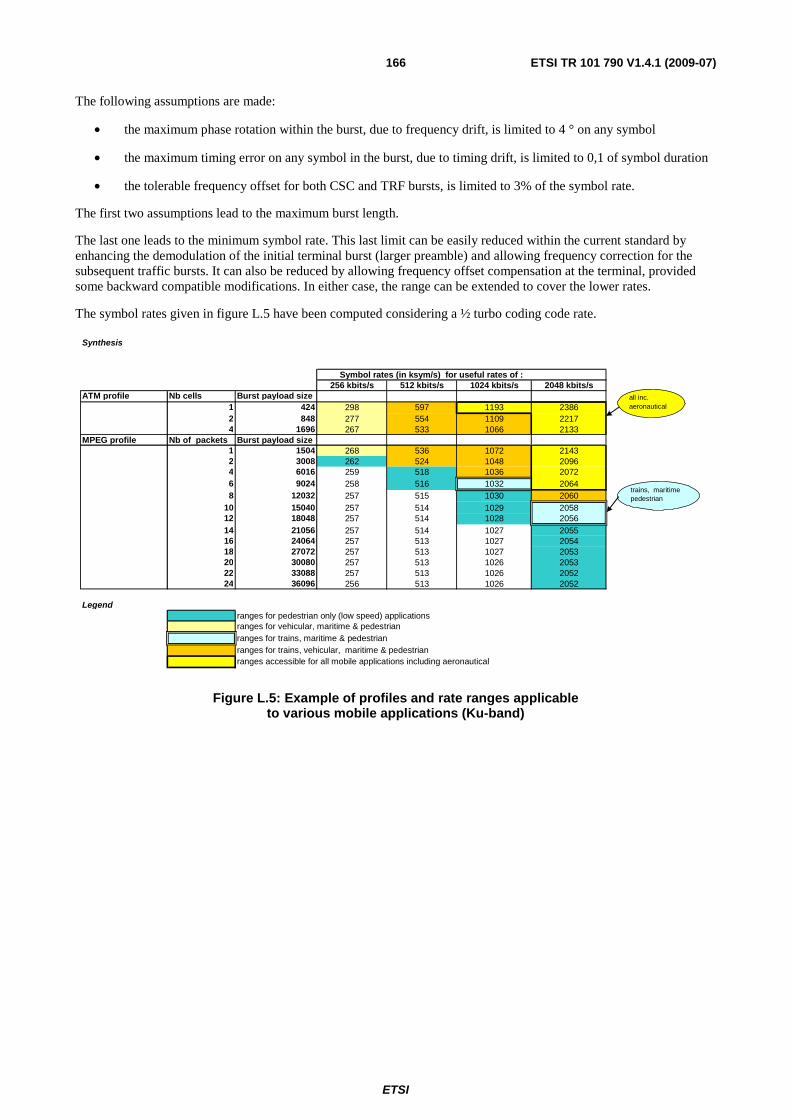
ETSI
ETSI TR 101 790 V1.4.1 (2009-07) 166
The following assumptions are made:
• the maximum phase rotation within the burst, due to frequency drift, is limited to 4 ° on any symbol
• the maximum timing error on any symbol in the burst, due to timing drift, is limited to 0,1 of symbol duration
• the tolerable frequency offset for both CSC and TRF bursts, is limited to 3% of the symbol rate.
The first two assumptions lead to the maximum burst length.
The last one leads to the minimum symbol rate. This last limit can be easily reduced within the current standard by enhancing the demodulation of the initial terminal burst (larger preamble) and allowing frequency correction for the subsequent traffic bursts. It can also be reduced by allowing frequency offset compensation at the terminal, provided some backward compatible modifications. In either case, the range can be extended to cover the lower rates.
The symbol rates given in figure L.5 have been computed considering a ½ turbo coding code rate.
Synthesis
Symbol rates (in ksym/s) for useful rates of : 256 kbits/s 512 kbits/s 1024 kbits/s 2048 kbits/s
ATM profile Nb cells Burst payload size 1 424 298 597 1193 23862 848 277 554 1109 22174 1696 267 533 1066 2133
MPEG profile Nb of packets Burst payload size 1 1504 268 536 1072 21432 3008 262 524 1048 20964 6016 259 518 1036 20726 9024 258 516 1032 20648 12032 257 515 1030 2060
10 15040 257 514 1029 205812 18048 257 514 1028 205614 21056 257 514 1027 205516 24064 257 513 1027 205418 27072 257 513 1027 205320 30080 257 513 1026 205322 33088 257 513 1026 205224 36096 256 513 1026 2052
Legend ranges for pedestrian only (low speed) applications ranges for vehicular, maritime & pedestrian
ranges for trains, maritime & pedestrian ranges for trains, vehicular, maritime & pedestrian
ranges accessible for all mobile applications including aeronautical
all inc. aeronautical
trains, maritime pedestrian
Figure L.5: Example of profiles and rate ranges applicable to various mobile applications (Ku-band)
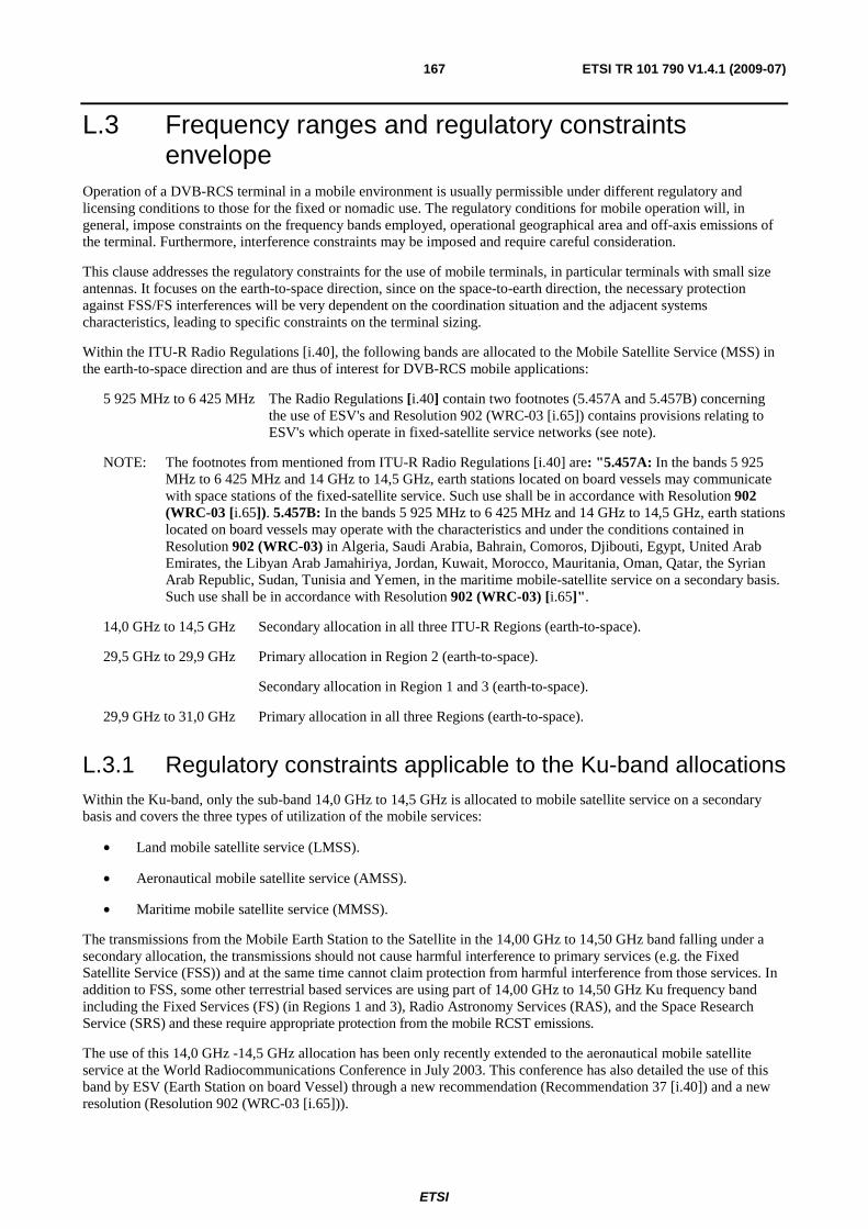
ETSI
ETSI TR 101 790 V1.4.1 (2009-07) 167
L.3 Frequency ranges and regulatory constraints envelope
Operation of a DVB-RCS terminal in a mobile environment is usually permissible under different regulatory and licensing conditions to those for the fixed or nomadic use. The regulatory conditions for mobile operation will, in general, impose constraints on the frequency bands employed, operational geographical area and off-axis emissions of the terminal. Furthermore, interference constraints may be imposed and require careful consideration.
This clause addresses the regulatory constraints for the use of mobile terminals, in particular terminals with small size antennas. It focuses on the earth-to-space direction, since on the space-to-earth direction, the necessary protection against FSS/FS interferences will be very dependent on the coordination situation and the adjacent systems characteristics, leading to specific constraints on the terminal sizing.
Within the ITU-R Radio Regulations [i.40], the following bands are allocated to the Mobile Satellite Service (MSS) in the earth-to-space direction and are thus of interest for DVB-RCS mobile applications:
5 925 MHz to 6 425 MHz The Radio Regulations [i.40] contain two footnotes (5.457A and 5.457B) concerning the use of ESV's and Resolution 902 (WRC-03 [i.65]) contains provisions relating to ESV's which operate in fixed-satellite service networks (see note).
NOTE: The footnotes from mentioned from ITU-R Radio Regulations [i.40] are: "5.457A: In the bands 5 925 MHz to 6 425 MHz and 14 GHz to 14,5 GHz, earth stations located on board vessels may communicate with space stations of the fixed-satellite service. Such use shall be in accordance with Resolution 902 (WRC-03 [i.65]). 5.457B: In the bands 5 925 MHz to 6 425 MHz and 14 GHz to 14,5 GHz, earth stations located on board vessels may operate with the characteristics and under the conditions contained in Resolution 902 (WRC-03) in Algeria, Saudi Arabia, Bahrain, Comoros, Djibouti, Egypt, United Arab Emirates, the Libyan Arab Jamahiriya, Jordan, Kuwait, Morocco, Mauritania, Oman, Qatar, the Syrian Arab Republic, Sudan, Tunisia and Yemen, in the maritime mobile-satellite service on a secondary basis. Such use shall be in accordance with Resolution 902 (WRC-03) [i.65]".
14,0 GHz to 14,5 GHz Secondary allocation in all three ITU-R Regions (earth-to-space).
29,5 GHz to 29,9 GHz Primary allocation in Region 2 (earth-to-space).
Secondary allocation in Region 1 and 3 (earth-to-space).
29,9 GHz to 31,0 GHz Primary allocation in all three Regions (earth-to-space).
L.3.1 Regulatory constraints applicable to the Ku-band allocations Within the Ku-band, only the sub-band 14,0 GHz to 14,5 GHz is allocated to mobile satellite service on a secondary basis and covers the three types of utilization of the mobile services:
• Land mobile satellite service (LMSS).
• Aeronautical mobile satellite service (AMSS).
• Maritime mobile satellite service (MMSS).
The transmissions from the Mobile Earth Station to the Satellite in the 14,00 GHz to 14,50 GHz band falling under a secondary allocation, the transmissions should not cause harmful interference to primary services (e.g. the Fixed Satellite Service (FSS)) and at the same time cannot claim protection from harmful interference from those services. In addition to FSS, some other terrestrial based services are using part of 14,00 GHz to 14,50 GHz Ku frequency band including the Fixed Services (FS) (in Regions 1 and 3), Radio Astronomy Services (RAS), and the Space Research Service (SRS) and these require appropriate protection from the mobile RCST emissions.
The use of this 14,0 GHz -14,5 GHz allocation has been only recently extended to the aeronautical mobile satellite service at the World Radiocommunications Conference in July 2003. This conference has also detailed the use of this band by ESV (Earth Station on board Vessel) through a new recommendation (Recommendation 37 [i.40]) and a new resolution (Resolution 902 (WRC-03 [i.65])).

ETSI
ETSI TR 101 790 V1.4.1 (2009-07) 168
Within Europe, ETSI has developed several standards:
• For low data rate mobile satellite earth stations (MESs) operating in the 11/12/14 GHz bands, EN 301 427, [i.41]
• For satellite mobile aircraft earth stations (AESs) operating in the 11/12/14 GHz bands, EN 302 186, [i.42]
• For satellite Earth Stations on board Vessels (ESVs) operating in the 11/12/14 GHz frequency bands allocated to the Fixed Satellite Service (FSS), EN 302 340, [i.47]
• For satellite Earth Stations on Trains (ESTs) operating in the 11/12/14 GHz frequency bands allocated to the Fixed Satellite Service (FSS), EN 302 448, [i.48]
• For Vehicle-Mounted Earth Stations (VMES) operating in the 12/14 GHz frequency bands, EN 302 977, [i.49]
These documents specify the minimum technical performance requirements of Mobile Station equipment with both transmit and receive capabilities for provision of mobile satellite service in the frequency bands given in table L.13.
Table L.13: Frequency bands for the equipment specified in the standards
Mode of Operation Frequency Band Transmit 14,00 GHz to 14,50 GHz Receive 10,70 GHz to 11,70 GHz Receive 12,50 GHz to 12,75 GHz
Regulations regarding the USA: due to the adoption of 2 degree satellite spacing in the orbital arc over the USA the FCC has introduced regulations that are somewhat more stringent than the ETSI ones. The reader is referred to [i.61], Part 25 (Satellite Communications) of the USA Code of Federal Regulations (47: Telecommunications). In addition, the FCC 04-286 report [i.64] and order provides some further background.
Within the ITU-Recommandation M.1643 "Technical and operational requirements for aircraft earth stations of aeronautical mobile-satellite service including those using fixed-satellite service network transponders in the band 14 -14,5 GHz (Earth-to-space)" [i.44] is also of interest.
L.3.1.1 Off-axis EIRP limits
Considering the appropriate ETSI regulatory documents it can be seen that for directional antennas, the maximum EIRP in any 40 kHz band from any Mobile satellite Earth Station in any direction φ degrees from the antenna main beam axis is not allowed to exceed the following limits within 3 ° of the geostationary orbit:
33 - 25 log (φ + δφ) - 10 log (K) dBW/40 kHz where 2,5 ° ≤ φ + δφ ≤ 7,0 °;
+12 - 10 log (K) dBW/40 kHz where 7,0 ° < φ + δφ ≤ 9,2 °;
36 - 25 log (φ + δφ) - 10 log (K) dBW/40 kHz where 9,2 ° < φ + δφ ≤ 48 °;
-6 - 10 log (K) dBW/40 kHz where 48 ° < φ + δφ ≤ 180 °;
where K is the number of simultaneous transmissions (K=1 for MF-TDMA system).
NOTE: These limits apply to satellites spaced at 3 ° apart. In the case of 2 ° spacing (reflected in ITU-R Recommendation S.728-1 [i.43]), a more constraining requirement - 8 dB less EIRP density- may be applied.
L.3.1.2 Particular constraints applicable to MMSS
The ESV terminal will have an antenna aperture greater than 1,2 meter (possibly 0,6 meter if agreed by the concerned licensing administrations).
Emission should cease if the distance to the coast line is lower than 125 km.
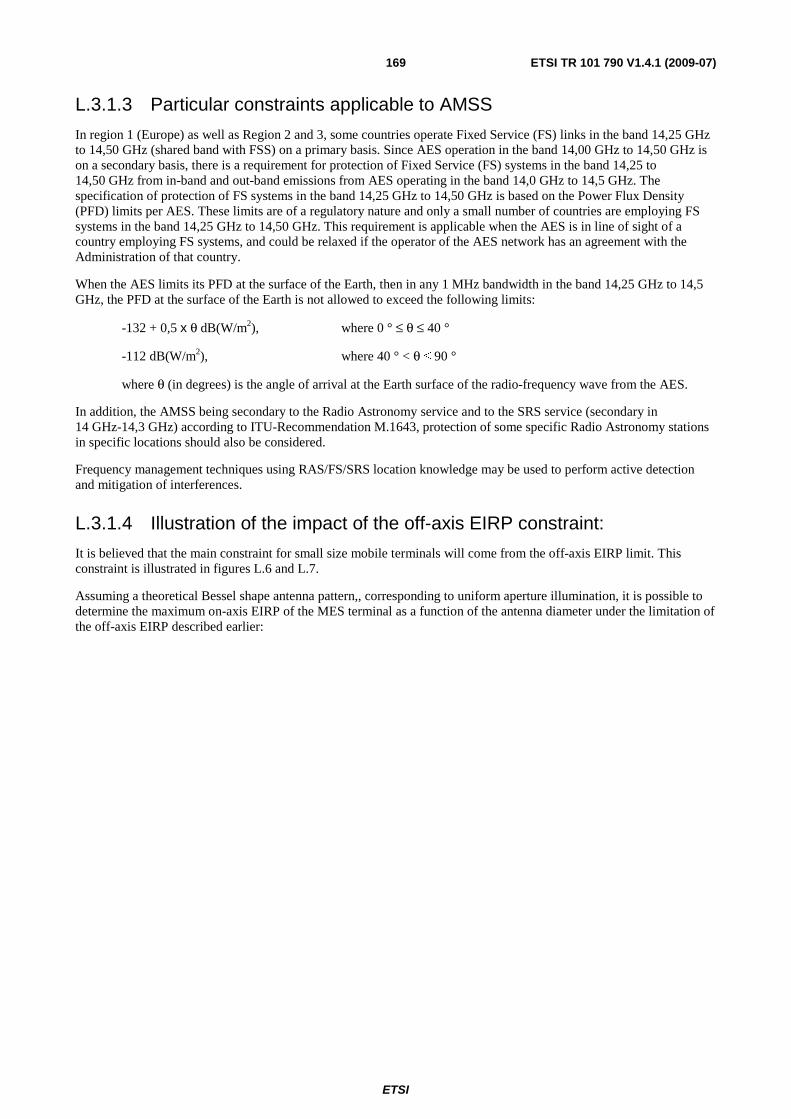
ETSI
ETSI TR 101 790 V1.4.1 (2009-07) 169
L.3.1.3 Particular constraints applicable to AMSS
In region 1 (Europe) as well as Region 2 and 3, some countries operate Fixed Service (FS) links in the band 14,25 GHz to 14,50 GHz (shared band with FSS) on a primary basis. Since AES operation in the band 14,00 GHz to 14,50 GHz is on a secondary basis, there is a requirement for protection of Fixed Service (FS) systems in the band 14,25 to 14,50 GHz from in-band and out-band emissions from AES operating in the band 14,0 GHz to 14,5 GHz. The specification of protection of FS systems in the band 14,25 GHz to 14,50 GHz is based on the Power Flux Density (PFD) limits per AES. These limits are of a regulatory nature and only a small number of countries are employing FS systems in the band 14,25 GHz to 14,50 GHz. This requirement is applicable when the AES is in line of sight of a country employing FS systems, and could be relaxed if the operator of the AES network has an agreement with the Administration of that country.
When the AES limits its PFD at the surface of the Earth, then in any 1 MHz bandwidth in the band 14,25 GHz to 14,5 GHz, the PFD at the surface of the Earth is not allowed to exceed the following limits:
-132 + 0,5 x θ dB(W/m2), where 0 ° ≤ θ ≤ 40 °
-112 dB(W/m2), where 40 ° < θ ≤ 90 °
where θ (in degrees) is the angle of arrival at the Earth surface of the radio-frequency wave from the AES.
In addition, the AMSS being secondary to the Radio Astronomy service and to the SRS service (secondary in 14 GHz-14,3 GHz) according to ITU-Recommendation M.1643, protection of some specific Radio Astronomy stations in specific locations should also be considered.
Frequency management techniques using RAS/FS/SRS location knowledge may be used to perform active detection and mitigation of interferences.
L.3.1.4 Illustration of the impact of the off-axis EIRP constraint:
It is believed that the main constraint for small size mobile terminals will come from the off-axis EIRP limit. This constraint is illustrated in figures L.6 and L.7.
Assuming a theoretical Bessel shape antenna pattern,, corresponding to uniform aperture illumination, it is possible to determine the maximum on-axis EIRP of the MES terminal as a function of the antenna diameter under the limitation of the off-axis EIRP described earlier:
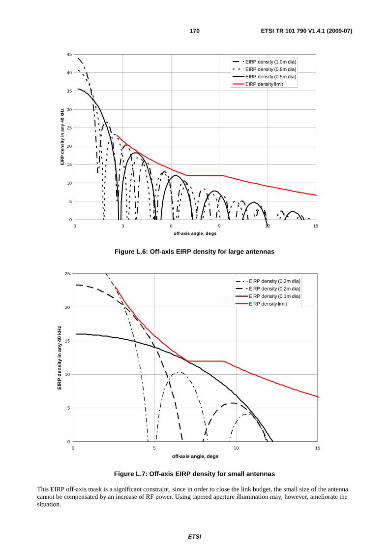
ETSI
ETSI TR 101 790 V1.4.1 (2009-07) 170
0
5
10
15
20
25
30
35
40
45
0 3 6 9 12 15
off-axis angle, degs
EIR
P d
ensi
ty in
an
y 40
kH
zEIRP density (1.0m dia)
EIRP density (0.8m dia)
EIRP density (0.5m dia)
EIRP density limit
Figure L.6: Off-axis EIRP density for large antennas
0
5
10
15
20
25
0 5 10 15
off-axis angle, degs
EIR
P d
ensi
ty in
an
y 40
kH
z
EIRP density (0.3m dia)
EIRP density (0.2m dia)
EIRP density (0.1m dia)
EIRP density limit
Figure L.7: Off-axis EIRP density for small antennas
This EIRP off-axis mask is a significant constraint, since in order to close the link budget, the small size of the antenna cannot be compensated by an increase of RF power. Using tapered aperture illumination may, however, ameliorate the situation.
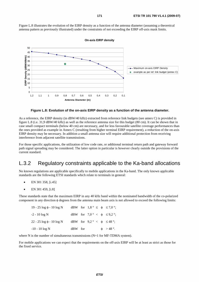
ETSI
ETSI TR 101 790 V1.4.1 (2009-07) 171
Figure L.8 illustrates the evolution of the EIRP density as a function of the antenna diameter (assuming a theoretical antenna pattern as previously illustrated) under the constraints of not exceeding the EIRP off-axis mask limits.
On-axis EIRP density
0
5
10
15
20
25
30
35
40
45
50
0,10,20,30,40,50,60,70,80,911,11,2
Antenna Diameter (m)
EIR
P D
ensi
ty (
dB
W/4
0kH
z)
Maximum on-axis EIRP Density
example as per ref. link budget (annex C)
Figure L.8: Evolution of the on-axis EIRP density as a function of the antenna diameter.
As a reference, the EIRP density (in dBW/40 kHz) extracted from reference link budgets (see annex C) is provided in figure L.8 (i.e. 31,9 dBW/40 kHz) as well as the reference antenna size for this budget (80 cm). It can be shown that in case small compact terminals (below 40 cm) are necessary, and for less favourable satellite coverage performances than the ones provided as example in Annex C (resulting from higher terminal EIRP requirement), a reduction of the on-axis EIRP density may be necessary. In addition a small antenna size will require additional protection from receiving interference from adjacent satellite transmissions.
For those specific applications, the utilization of low code rate, or additional terminal return path and gateway forward path signal spreading may be considered. The latter option in particular is however clearly outside the provisions of the current standard.
L.3.2 Regulatory constraints applicable to the Ka-band allocations No known regulations are applicable specifically to mobile applications in the Ka-band. The only known applicable standards are the following ETSI standards which relate to terminals in general:
• EN 301 358, [i.45]
• EN 301 459, [i.8]
These standards state that the maximum EIRP in any 40 kHz band within the nominated bandwidth of the co-polarized component in any direction φ degrees from the antenna main beam axis is not allowed to exceed the following limits:
19 - 25 log φ - 10 log N dBW for 1,8 ° ≤ φ ≤ 7,0 °;
-2 - 10 log N dBW for 7,0 ° < φ ≤ 9,2 °;
22 - 25 log φ - 10 log N dBW for 9,2 ° < φ ≤ 48 °;
-10 - 10 log N dBW for φ > 48 °.
where N is the number of simultaneous transmissions (N=1 for MF-TDMA system).
For mobile applications we can expect that the requirements on the off-axis EIRP will be at least as strict as those for the fixed service.
ETSI
ETSI TR 101 790 V1.4.1 (2009-07) 172
L.4 DVB-RCS coverage of mobility management This clause identifies the existing mechanisms in the current standard able to meet to mobility management requirements. The mobility management requirements are two-fold:
• the access from a mobile terminal to DVB-RCS forward signalling, wherever it is located within the satellite coverage area;
• the handover management (typically from one beam to another within the satellite coverage), including two phases:
1) detection and preparation of beam handover;
2) handover execution and associated signalling.
L.4.1 Access to forward link signalling The mobile terminal should be able to access the forward link signalling wherever it is in the satellite coverage area. At log-on, the DVB-RCS terminal is able to access the forward link provided that the two following information data are stored in the RCST as power up configuration data: forward link location details (in particular transponder frequency) for the forward link start-up Transport Stream and population_id value.
To access the service, the mobile terminal will have to be configured with a list of beam_id and associated start-up Transport Streams.
The RCST is then able to access to its Forward Link service information, by scanning linkage descriptors to find the descriptor containing its population_id. In a mobile system, it is proposed that the population_id should not be uniquely associated to a beam, but on the contrary that a population_id associated to mobile terminal can be common to all beams in the satellite coverage area. In that case, a given population_id parameter can be present in several RCS Map Tables within a system (one RCS Map Table per beam). The current standard [i.2] does not restrict the population_id to a specific association to a beam and is therefore compatible with this proposal.
L.4.2 Handover detection and preparation The motion of an active terminal within the satellite coverage area, may lead to the requirement of a beam handover without interruption of service for the end-user. Handover will be required when the terminal comes to the edge of the satellite beam.
The handover decision can be made on the basis of mobile terminal position or on the basis of link quality measurements. The current standard [i.2] includes means to monitor return link signal quality (as for example through the available return link control feedback loop mechanisms) and means to transmit the forward link signal quality perceived by the RCST terminal to the NCC. This signalling data can be transmitted in the SAC optional sub-field (ACM sub-field) that supports ACM in DVB-S2 links. Measurements at terminal level are also facilitated as DVB terminal receivers have built-in Eb/No estimators. The decision/detection algorithms should be optimized to allow differentiating fades due to the motion of the mobile terminals from a beam to another, from those due to propagation effects. This will be facilitated by the different time-constant and fade range associated to these two different effects.
The decision to perform a terminal handover can thus be made at NCC level on the basis of measurements, completed if available by knowledge of terminal location within the coverage (for example by SNMP messages supporting position update information).
L.4.3 Handover execution and associated signalling The NCC will then signal to the terminal all the necessary new configuration parameters needed for the handover (configuration to a new beam and transponder, as well as logical parameters if necessary). The current standard [i.2] allows the transmission of those parameters through Unicast TIM dedicated to the terminal involved in the handover process.
The following descriptors of the TIM, as defined in the current standard, can be used during the handover process.

ETSI
ETSI TR 101 790 V1.4.1 (2009-07) 173
• Satellite Forward Link Descriptor: can be used to provide to the terminal the configuration parameters for the new beam and new transponder (Beam_Id, new TDM carrier frequency, etc.).
• Satellite Return Link Descriptor: can provide configuration parameters for the return link transponder (in particular Superframe_Id).
• SYNC assign Descriptor: can be used to provide the instant of change for the terminal, i.e the time at which the handover is effective. This information is given through the "SYNC_start_superframe" count. The SYNC assign descriptor allows also to define new SYNC assignment period if this is needed.
• Log-on initialize descriptor: can be used to provide modification to the terminal logical parameters if needed.
• Network Layer Info descriptor: can be used as an alternative method to provide the time of handover.
To facilitate the handover and reduce the handover time, thus ensuring the synchronization is maintained, and providing no or minimum service interruption to the end-user, one possibility is that the transport stream composition i.e. frequency plan structure (SCT, FCT, TCT) is common to the beams in the coverage, and that PID plan from one beam to the other is maintained.
L.5 Additional considerations for mobile applications This clause provides some additional propositions related to the use of the DVB-RCS standard [i.2] to handle mobility.
L.5.1 Signalling table transmission in mobile environments - practical case of TBTP
The applicability of the DVB-RCS to mobile environment may result in a forward link being more sensitive to errors, impacting the robustness in signalling table transmission, hence potentially leading to degradation of traffic data transmission performances.
This clause addresses the specific case of the TBTP, and the impact a loss of one TBTP table may have on the network performances, in particular when the "repeating assignment" option is used.
The utilization of "repeating assignment" may lead to two specific problems when TBTP is in error or not received at terminal level:
The first problem occurs when the mobile terminal has not received a "assignment release" for a slot previously assigned by the NCC with "repeating assignment" type. The terminal may continue to send data traffic in this slot, which can cause collisions if the slot has been simultaneously allocated to another terminal.
The second problem occurs when the mobile terminal has not received the first assignment, assigned by the NCC using the "repeating assignment" method. In that case, the terminal will not use the slot, this resulting in a loss of capacity during several superframes (the slot capacity will be lost for the network).
There are three possibilities for resolving these problems:
• The first possibility would be to avoid the "repeating assignment" method if the forward link is sensitive to errors.
• The second possibility applies when the "repeating assignment" method is used: The mobile terminal should read every TBTP and in the case it has lost a TBTP, it should cease transmission in the slot that was assigned with "repeating assignment" method.
• The third possibility applies when the "repeating assignment" method is used: When the NCC has sent a "repeating assignment" assignment type, and has not received any traffic data in this slot, it should repeat this assignment until the slot is effectively used by the terminal to who the NCC made the assignment.

ETSI
ETSI TR 101 790 V1.4.1 (2009-07) 174
L.5.2 Consideration for mobile antenna in mobile environment As indicated in the introduction, the present annex focuses on the IDU part of the terminal, assuming that the specific ODU definition (in particular the antenna) is suitable for the required mobility environment and applications may be required. This clause briefly addresses the issue that the moving condition makes the mobile antenna frequently miss a target satellite due to an obstacle (Non-LOS states). In this operating environment, it is proposed that the antenna should be able to stop signal transmission within specified time. Specific IDU/ODU command should be used in that case, as addressed in annex B of the present document.
ETSI
ETSI TR 101 790 V1.4.1 (2009-07) 175
Annex M: Bibliography http://www-elec.enst-bretagne.fr/publication/publi.shtml, Elect. Letters, Vol. 35, N 1, pp. 39-40, January 1999, C. Berrou and M. Jézéquel: "Non binary convolutional codes for turbo coding".
http://sunsite.informatik.rwth-aachen.de/dblp/db/indices/a-tree/v/Viterbi:Andrew_J=.html, IEEE Journal on Select. Areas in Comm., vol. 16, pp. 260-264, February 1998, A. J. Viterbi: "An intuitive justification and simplified implementation of MAP decoder for convolutional codes".
http://www-elec.enst-bretagne.fr/publication/publi.shtml, GRETSI, Vannes, France, September 1999, A. Dingninou, F. Raouafi et C. Berrou: "Organisation de la mémoire dans un turbo décodeur utilisant l'algorithme SUB-MAP".
http://www-elec.enst-bretagne.fr, Proceedings of the 2nd Symposium on Turbo codes and related topics, 4 - 7 September 2000: Miscellaneous.
IETF RFC 2486: "The Network Access Identifier".
ISO 8824: "Information technology - Open Systems Interconnection - Specification of Abstract Syntax Notation One (ASN.1)".
IETF RFC 1907: "Management Information Base for Version 2 of the Simple Network Management Protocol (SNMPv2)".
ITU-T Recommendation H.222.0: "Information technology - Generic coding of moving pictures and associated audio information: Systems".
ITU-T Recommendation I.361: "B-ISDN ATM layer specification".
IETF RFC 1518: "An Architecture for IP Address Allocation with CIDR".
IETF RFC 1519: "Classless Inter-Domain Routing (CIDR):an Address Assignment and Aggregation Strategy".

ETSI
ETSI TR 101 790 V1.4.1 (2009-07) 176
History
Document History
V1.1.1 September 2001 Publication
V1.2.1 January 2003 Publication
V1.3.1 September 2006 Publication
V1.4.1 July 2009 Publication
Related Documents