International Journal of Engineering & Computer Science IJECS-IJENS Vol:13 No:05 6 131805-7070-IJECS-IJENS © October 2013 IJENS I J E N S EMI Prevention of CAN-Bus-Based Communication in Battery Management Systems Chin-Long Wey, Chung-Hsien Hsu*, Kun-Chun Chang*, Ping-Chang Jui*, and Muh-Tian Shiue* Department of Electrical Engineering, National Chiao Tung University, Hsinchu, Taiwan *Department of Electrical Engineering, National Central University, Jhongli, Taiwan Abstract— Controller Area Network (CAN) bus has been popularly employed in most of vehicles and it will be heavily involved to the electric vehicle (EV) applications. A vehicle is a noisy system, with electromagnetic interference (EMI) over a wide range of frequencies. EMI generated by the inductive loads is the major cause of performance degradation of CAN bus communications. In order to enhance and protect the reliability and robustness of the CAN bus communication and to maintain safe operation of the battery stack, galvanic isolator is required for the data transmission. This study compares two different galvanic isolators, Optocoupler and Digital Isolator, and three different isolation schemes are evaluated by their protection capability for various EMI affected signals. The best isolation scheme has been recommended for EMI prevention of the CAN- bus-based BMS. Index Term-- Controller Area Network (CAN), Battery Management System (BMS), Electromagnetic Interference (EMI), Galvanic Isolators, Electrical Vehicle. I. INTRODUCTION Battery Management System (BMS) is simply battery monitoring which keeps checking on the key operational parameters during charging and discharging such as voltages, currents, and temperatures (internal and ambient). The BMS normally provides inputs to protection devices which generate alarms or disconnect the battery from the load or charger when any of the parameters become out of limits. The major objectives of BMS are [1,2]: (1) to protect the cells or the battery from damage; (2) to prolong the life of the battery; and (3) to maintain the battery in a state in which it can fulfill the functional requirements of the application for which it was specified. Thus, the BMS may incorporate one or more of the following functions: cell protection, charge control, demand management, state of charge (SOC) determination, state of health (SOH) determination, cell balancing, communication, and etc. The BMS communicates with other system devices or with external equipment via a data link for performance monitoring, data logging, diagnostics, or system parameters setting. The choice of the communication protocol is determined by the application. The System Management Bus (SMBus) [3] has been commonly used for the BMSs applied for notebook PC. Recently, Controller Area Network (CAN) bus has been popularly employed in most of vehicles and it has been heavily involved to the Electric Vehicle (EV) application. The CAN bus is very robust with error detection and fault tolerance, but it carries significant communications overhead and high materials cost. While an interface from the battery system to the main vehicle CAN bus may be desirable, I 2 C communications can be advantageous within the battery pack. The BMS system with CAN bus allows the vehicle system to detect whether the battery is overloaded through the CAN bus nodes when the vehicle starts or overloads, and then temporarily disables non- safety-critical devices, such as air condition, entertainment systems, and etc., to reduce the battery load to prolong the life of battery. The battery stack voltage can be as high as 400 V in many EV’s, this high voltage is needed to deliver enough power to the motor. A vehicle is a noisy system, with electromagnetic interference (EMI) over a wide range of frequencies. EMI generated by the inductive loads has been found to be the major cause of performance degradation of CAN bus communications [4-6]. The ultimate goal of this study is to enhance and protect the reliability and robustness of the CAN bus communication and to maintain safe operation of the battery stack for data transmission from high voltage battery to low voltage electronics elsewhere in the vehicle. The use of galvanic isolators [7] can achieve this goal. Therefore, this study will compare two different galvanic isolators, Optocoupler [8] and Digital Isolator [9], and evaluate the protection capability of three different isolation schemes for various EMI affected signals. Results of this study will demonstrate that the best isolation scheme is recommended for EMI prevention of the CAN-bus-based BMS. In the next section, the CAN-bus-based BMS architectures are briefly reviewed. The effect of EMI is also briefly discussed. Section III compares two different galvanic isolators and evaluates three different isolation schemes using these isolators. A concluding remark is given in Section IV.

Welcome message from author
This document is posted to help you gain knowledge. Please leave a comment to let me know what you think about it! Share it to your friends and learn new things together.
Transcript
International Journal of Engineering & Computer Science IJECS-IJENS Vol:13 No:05 6
131805-7070-IJECS-IJENS © October 2013 IJENS I J E N S
EMI Prevention of CAN-Bus-Based Communication
in Battery Management Systems
Chin-Long Wey, Chung-Hsien Hsu*, Kun-Chun Chang*, Ping-Chang Jui*, and Muh-Tian Shiue*
Department of Electrical Engineering, National Chiao Tung University, Hsinchu, Taiwan
*Department of Electrical Engineering, National Central University, Jhongli, Taiwan
Abstract— Controller Area Network (CAN) bus has been
popularly employed in most of vehicles and it will be heavily
involved to the electric vehicle (EV) applications. A vehicle is a
noisy system, with electromagnetic interference (EMI) over a wide
range of frequencies. EMI generated by the inductive loads is the
major cause of performance degradation of CAN bus
communications. In order to enhance and protect the reliability
and robustness of the CAN bus communication and to maintain
safe operation of the battery stack, galvanic isolator is required
for the data transmission. This study compares two different
galvanic isolators, Optocoupler and Digital Isolator, and three
different isolation schemes are evaluated by their protection
capability for various EMI affected signals. The best isolation
scheme has been recommended for EMI prevention of the CAN-
bus-based BMS.
Index Term-- Controller Area Network (CAN), Battery
Management System (BMS), Electromagnetic Interference (EMI),
Galvanic Isolators, Electrical Vehicle.
I. INTRODUCTION
Battery Management System (BMS) is simply battery
monitoring which keeps checking on the key operational
parameters during charging and discharging such as voltages,
currents, and temperatures (internal and ambient). The BMS
normally provides inputs to protection devices which generate
alarms or disconnect the battery from the load or charger when
any of the parameters become out of limits. The major
objectives of BMS are [1,2]: (1) to protect the cells or the
battery from damage; (2) to prolong the life of the battery; and
(3) to maintain the battery in a state in which it can fulfill the
functional requirements of the application for which it was
specified. Thus, the BMS may incorporate one or more of the
following functions: cell protection, charge control, demand
management, state of charge (SOC) determination, state of
health (SOH) determination, cell balancing, communication,
and etc.
The BMS communicates with other system devices or with
external equipment via a data link for performance monitoring,
data logging, diagnostics, or system parameters setting. The
choice of the communication protocol is determined by the
application. The System Management Bus (SMBus) [3] has
been commonly used for the BMSs applied for notebook PC.
Recently, Controller Area Network (CAN) bus has been
popularly employed in most of vehicles and it has been heavily
involved to the Electric Vehicle (EV) application. The CAN bus
is very robust with error detection and fault tolerance, but it
carries significant communications overhead and high materials
cost. While an interface from the battery system to the main
vehicle CAN bus may be desirable, I2C communications can be
advantageous within the battery pack. The BMS system with
CAN bus allows the vehicle system to detect whether the
battery is overloaded through the CAN bus nodes when the
vehicle starts or overloads, and then temporarily disables non-
safety-critical devices, such as air condition, entertainment
systems, and etc., to reduce the battery load to prolong the life
of battery.
The battery stack voltage can be as high as 400 V in many
EV’s, this high voltage is needed to deliver enough power to the
motor. A vehicle is a noisy system, with electromagnetic
interference (EMI) over a wide range of frequencies. EMI
generated by the inductive loads has been found to be the
major cause of performance degradation of CAN bus
communications [4-6].
The ultimate goal of this study is to enhance and protect the
reliability and robustness of the CAN bus communication and
to maintain safe operation of the battery stack for data
transmission from high voltage battery to low voltage
electronics elsewhere in the vehicle. The use of galvanic
isolators [7] can achieve this goal. Therefore, this study will
compare two different galvanic isolators, Optocoupler [8] and
Digital Isolator [9], and evaluate the protection capability of
three different isolation schemes for various EMI affected
signals. Results of this study will demonstrate that the best
isolation scheme is recommended for EMI prevention of the
CAN-bus-based BMS.
In the next section, the CAN-bus-based BMS architectures are briefly reviewed. The effect of EMI is also briefly discussed. Section III compares two different galvanic isolators and evaluates three different isolation schemes using these isolators. A concluding remark is given in Section IV.
International Journal of Engineering & Computer Science IJECS-IJENS Vol:13 No:05 7
131805-7070-IJECS-IJENS © October 2013 IJENS I J E N S
II. BACKGROUND
This section reviews the architecture of CAN-bus-based BMS and EMI effects to CAN bus.
2.1 CAN-bus-based BMS
In order to improve the conventional rechargeable batteries by
indicating the residual power therein, a smart battery was
jointly developed with the Automotive Research & Test Center
[10], Taiwan, under the collaborative research project “Smart
Battery Management System with Distributed Battery Units”
[11] sponsored by the Ministry of Economic Affairs (MOEA),
Taiwan. The battery implements a residual power monitoring
device, a temperature sensor and other sensors to detect the
variation of the charge-discharge cycle taking place in the
smart battery, so as to prevent the smart battery from
overcharge or over-discharge.
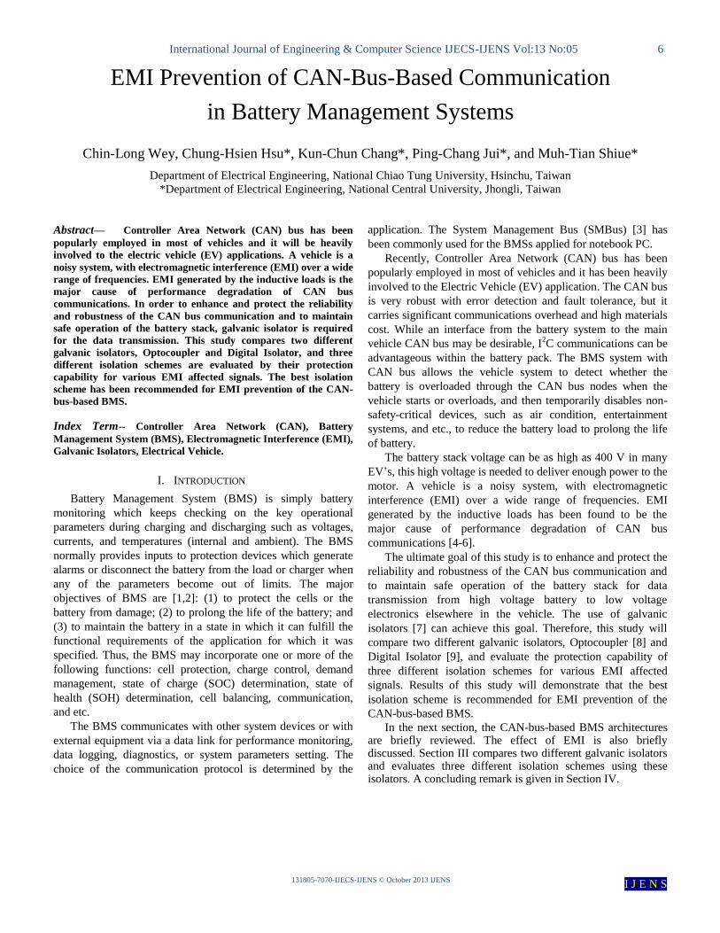
Fig.1(a) shows the developed BMS under the project. The
SOC of each cell in the BMS can be monitored by a BIM
(Battery Interconnect Manager), as shown in Fig. 1(b), where
each BIM is instructed by the BWM (Battery Module
Manager), as shown in Fig. 1(c), to communicate with its next
neighbor BIM through a communication bus. Once
overcharging or over-discharging of a cell occurs, the BIM
reports to its supervised BWM and self-purge to maintain the
safety of the system. The BIM configuration provides very
easy interface with its neighbors and offer the salient feature of
plug-and-play.
Due the insufficient bandwidth of the SMBus and high
battery stacked voltage for vehicle applications, the CAN bus
was employed in our BMS development. The CAN bus is very
robust with error detection and fault tolerance, but it carries
significant communications overhead and high materials cost.
While an interface from the battery system to the main vehicle
CAN bus may be desirable, I2C communications can be
advantageous within the battery pack.
(a)
(b)
(c)
Fig. 1 Developed BMS: (a) Block Diagram; (b) Battery Interconnect Manager (BIM); and (c) Battery Module Manager (BMM).
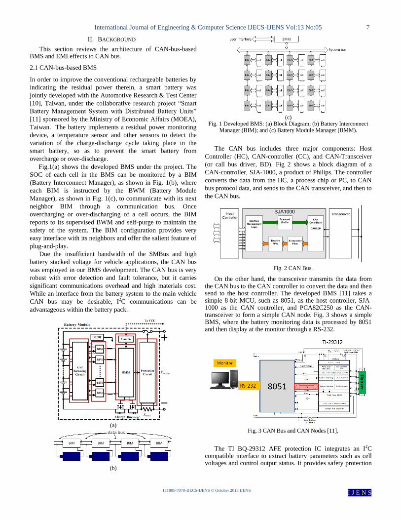
The CAN bus includes three major components: Host
Controller (HC), CAN-controller (CC), and CAN-Transceiver
(or call bus driver, BD). Fig 2 shows a block diagram of a
CAN-controller, SJA-1000, a product of Philips. The controller
converts the data from the HC, a process chip or PC, to CAN
bus protocol data, and sends to the CAN transceiver, and then to
the CAN bus.
Fig. 2 CAN Bus.
On the other hand, the transceiver transmits the data from the CAN bus to the CAN controller to convert the data and then send to the host controller. The developed BMS [11] takes a simple 8-bit MCU, such as 8051, as the host controller, SJA-1000 as the CAN controller, and PCA82C250 as the CAN-transceiver to form a simple CAN node. Fig. 3 shows a simple BMS, where the battery monitoring data is processed by 8051 and then display at the monitor through a RS-232.
Fig. 3 CAN Bus and CAN Nodes [11].
The TI BQ-29312 AFE protection IC integrates an I
2C
compatible interface to extract battery parameters such as cell voltages and control output status. It provides safety protection
International Journal of Engineering & Computer Science IJECS-IJENS Vol:13 No:05 8
131805-7070-IJECS-IJENS © October 2013 IJENS I J E N S
for overcharge, overload, short-circuit, and overvoltage conditions in conjunction with the battery management host. It allows user to program the parameters such as current protection thresholds and delays for overload and short-circuit during charge and discharge. The 8051 maintains an accurate record of available capacity and other critical parameters of the battery pack and reports the information to the system host controller over the RS232.
2.2 EMI Effects on CAN BUS
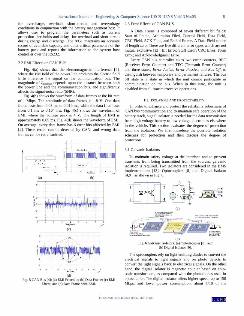
Fig. 4(a) shows that the electromagnetic interference [4], where the EM field of the power line produces the electric field E to inference the signal on the communication bus. The magnitude of Iinference depends upon the distance between both the power line and the communication bus, and significantly affects the signal-noise ratio (SNR).
Fig. 4(b) shows the waveform of data frames at the bit rate
of 1 Mbps. The amplitude of data frames is 1.8 V. One data
frame lasts from 0.08 ms to 0.019 ms, while the data filed lasts
from 0.1 ms to 0.164 ms. Fig. 4(c) shows the waveform of
EMI, where the voltage peak is 4 V. The length of EMI is
approximately 0.65 ms. Fig. 4(d) shows the waveform of EMI.
On average, every data frame has 6 error bits affected by EMI
[4]. These errors can be detected by CAN, and wrong data
frames can be retransmitted.
(a) (b)
(c)
(d)
Fig. 5 CAN Bus [4]: (a) EMI Principle; (b) Data Frame; (c) EMI
Effect; and (d) Data Frame with EMI.
2.3 Error Effects of CAN BUS
A Data Frame is composed of seven different bit fields:
Start of Frame, Arbitration Filed, Control Field, Data Field,
CRC Field, ACK Field, and End of Frame. A Data Field can be
of length zero. There are five different error types which are not
mutual exclusive [12]: Bit Error; Stuff Error; CRC Error; Form
Error; and Acknowledgment Error.
Every CAN bus controller takes two error counters, REC
(Receiver Error Counter) and TEC (Transmit Error Counter)
and three states, Error Active, Error Passive, and Bus Off, to
distinguish between temporary and permanent failures. The bus
off state is a state in which the unit cannot participate in
communication on the bus. When in this state, the unit is
disabled from all transmit/receive operations.
III. ISOLATORS AND PROTECTABILITY
In order to enhance and protect the reliability robustness of
CAN bus communication and to maintain safe operation of the
battery stack, signal isolator is needed for the data transmission
from high voltage battery to low voltage electronics elsewhere
in the vehicle. This section evaluates the degree of protection
from the isolators. We first introduce the possible isolation
schemes for protection and then discuss the degree of
protection.
3.1 Galvanic Isolators
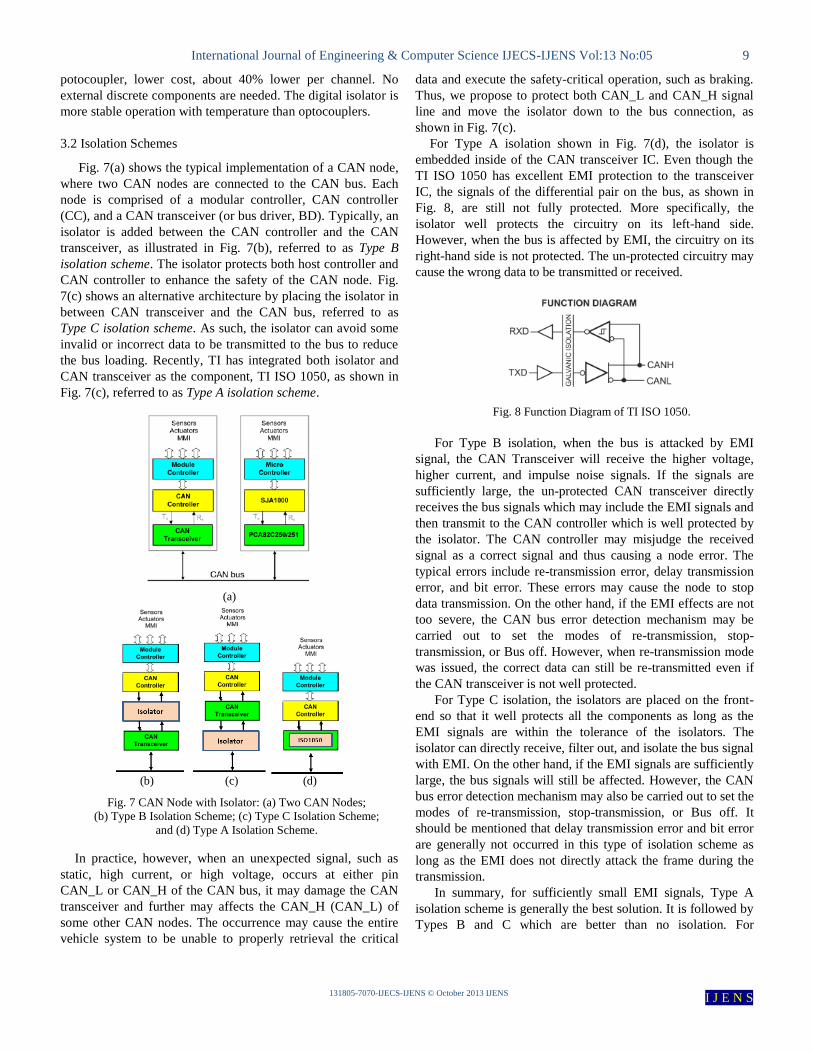
To maintain safety voltage at the interface and to prevent
transients from being transmitted from the sources, galvanic
isolation is required. Two isolators are considered in the BMS
implementation [13]: Optocouplers [8] and Digital Isolator
[4,9], as shown in Fig. 6.
(a)
(b)
Fig. 6 Galvanic Isolators: (a) Optodecupler [8]; and
(b) Digital Isolator [9].
The optocouplers rely on light emitting diodes to convert the
electrical signals to light signals and on photo detects to
convert the light signals back to electrical signals. On the other
hand, the digital isolator is magnetic coupler based on chip-
scale transformers, as compared with the photodiodes used in
optocoupler. The digital isolator offers higher speed, up to 150
Mbps, and lower power consumption, about 1/10 of the
International Journal of Engineering & Computer Science IJECS-IJENS Vol:13 No:05 9
131805-7070-IJECS-IJENS © October 2013 IJENS I J E N S
potocoupler, lower cost, about 40% lower per channel. No
external discrete components are needed. The digital isolator is
more stable operation with temperature than optocouplers.
3.2 Isolation Schemes
Fig. 7(a) shows the typical implementation of a CAN node,
where two CAN nodes are connected to the CAN bus. Each
node is comprised of a modular controller, CAN controller
(CC), and a CAN transceiver (or bus driver, BD). Typically, an
isolator is added between the CAN controller and the CAN
transceiver, as illustrated in Fig. 7(b), referred to as Type B
isolation scheme. The isolator protects both host controller and
CAN controller to enhance the safety of the CAN node. Fig.
7(c) shows an alternative architecture by placing the isolator in
between CAN transceiver and the CAN bus, referred to as
Type C isolation scheme. As such, the isolator can avoid some
invalid or incorrect data to be transmitted to the bus to reduce
the bus loading. Recently, TI has integrated both isolator and
CAN transceiver as the component, TI ISO 1050, as shown in
Fig. 7(c), referred to as Type A isolation scheme.
(a)
(b) (c) (d)
Fig. 7 CAN Node with Isolator: (a) Two CAN Nodes;
(b) Type B Isolation Scheme; (c) Type C Isolation Scheme;
and (d) Type A Isolation Scheme.
In practice, however, when an unexpected signal, such as
static, high current, or high voltage, occurs at either pin
CAN_L or CAN_H of the CAN bus, it may damage the CAN
transceiver and further may affects the CAN_H (CAN_L) of
some other CAN nodes. The occurrence may cause the entire
vehicle system to be unable to properly retrieval the critical
data and execute the safety-critical operation, such as braking.
Thus, we propose to protect both CAN_L and CAN_H signal
line and move the isolator down to the bus connection, as
shown in Fig. 7(c).
For Type A isolation shown in Fig. 7(d), the isolator is
embedded inside of the CAN transceiver IC. Even though the
TI ISO 1050 has excellent EMI protection to the transceiver
IC, the signals of the differential pair on the bus, as shown in
Fig. 8, are still not fully protected. More specifically, the
isolator well protects the circuitry on its left-hand side.
However, when the bus is affected by EMI, the circuitry on its
right-hand side is not protected. The un-protected circuitry may
cause the wrong data to be transmitted or received.
Fig. 8 Function Diagram of TI ISO 1050.
For Type B isolation, when the bus is attacked by EMI
signal, the CAN Transceiver will receive the higher voltage,
higher current, and impulse noise signals. If the signals are
sufficiently large, the un-protected CAN transceiver directly
receives the bus signals which may include the EMI signals and
then transmit to the CAN controller which is well protected by
the isolator. The CAN controller may misjudge the received
signal as a correct signal and thus causing a node error. The
typical errors include re-transmission error, delay transmission
error, and bit error. These errors may cause the node to stop
data transmission. On the other hand, if the EMI effects are not
too severe, the CAN bus error detection mechanism may be
carried out to set the modes of re-transmission, stop-
transmission, or Bus off. However, when re-transmission mode
was issued, the correct data can still be re-transmitted even if
the CAN transceiver is not well protected.
For Type C isolation, the isolators are placed on the front-
end so that it well protects all the components as long as the
EMI signals are within the tolerance of the isolators. The
isolator can directly receive, filter out, and isolate the bus signal
with EMI. On the other hand, if the EMI signals are sufficiently
large, the bus signals will still be affected. However, the CAN
bus error detection mechanism may also be carried out to set the
modes of re-transmission, stop-transmission, or Bus off. It
should be mentioned that delay transmission error and bit error
are generally not occurred in this type of isolation scheme as
long as the EMI does not directly attack the frame during the
transmission.
In summary, for sufficiently small EMI signals, Type A
isolation scheme is generally the best solution. It is followed by
Types B and C which are better than no isolation. For

International Journal of Engineering & Computer Science IJECS-IJENS Vol:13 No:05 10
131805-7070-IJECS-IJENS © October 2013 IJENS I J E N S
sufficiently large EMI signals or the EMI signals are negative
Vp-p, however, only Type C can survive.
3.3 Experimental Results
A complete CAN data frame includes ID frame, Control
frame, CRC frame, and END frame, as illustrated in Fig. 9(a).
In these experiments, EMI signals with various amplitude and
offset voltages are applied, as shown in Fig. 9(b).
(a)
(b)
Fig. 9 (a) Frames in CAN; and (b) EMI signals Applied to CAN Bus.
If the amplitude and offset voltage of the EMI signals do not
completely destroy the CAN data frame, the CAN bus error
detection mechanism may be carried out to set the modes of re-
transmission, stop-transmission, or Bus off. The re-
transmission may be issued, as illustrated in Fig. 10(a)-10(c),
while stop-transmission or bus off is issued, as shown in Fig.
10(d). Note that the upper signal waveforms (in yellow) in Fig.
10(a)-10(d) represent the received signals by the controller,
while the lower signal waveforms (in light blue) are the bus
signals.
(a)
(b)
(c)
(d)
Fig. 10 EMI affected signals to CAN Bus.
A. Type A Isolation Scheme
The TI ISO1050 is used as the isolator for Type A isolation
scheme. Fig. 11(a) is the CAN communication of two nodes
with Type A isolation scheme. In this experiment, the data
frame is partially affected by EMI, i.e., the front part is affected
by EMI. Since the transmitted data “D6” is affected, the
receiver will not be able to receive the ACK signal. Since the
controller is well protected by the isolator, the affected data will
then be transmitted.
(a) Type A

International Journal of Engineering & Computer Science IJECS-IJENS Vol:13 No:05 11
131805-7070-IJECS-IJENS © October 2013 IJENS I J E N S
(b)
Fig. 11 Type A Isolation Scheme: (a) Experiment Set-up;
and (b) Measurement Results.
B. Type B Isolation Scheme
In this experiment, the optocoupler is used as the isolator to
protect the CAN nodes. The optocouplers rely on light emitting
diodes to convert the electrical signals to light signals and on
photo detects to convert the light signals back to electrical
signals.
Type B isolation scheme in Fig. 7(b) is implemented as
shown in Fig. 12(a). Fig. 12(b) and 12(c) illustrate the probed
signal waveforms, where Channels 1 and 2 respectively probes
the protected signals received by the CAN controller in Node
#2 and the bus signals. With the amplitude of 10 Vp-p EMI
signals (in light blue) in Fig. 12(b), the bus signal is affected.
After being demodulated by the CAN bus driver (without
protection), the bus signals (in yellow) is destroyed causing
form error, CRC error, CRC error, ACK error, stuff error, and
bit error. The CAN bus error detection mechanism may be
carried out to set the modes of re-transmission or stop-
transmission. In this case, some bytes may be demodulated
correctly which is better than no protection in Type A. In Fig.
12(c), with an amplitude of 2 Vp-p EMI signal, the affected data
still can be demodulated correctly by the bus driver, but the
ACK signal still cannot be received. As such, the re-
transmission mode may be issued.
(a)
(b)
(c)
Fig. 10 Type B Isolation Scheme.
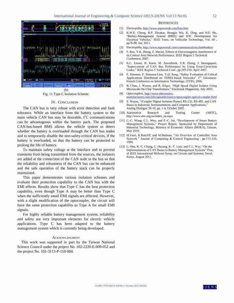
C. Type C Isolation Scheme
This experiment also takes the optocoupler as the isolator to
protect the CAN nodes. Type C isolation scheme in Fig. 7(c) is
implemented as shown in Fig. 13(a). Fig. 13(b) shows the
probed signal waveforms, where Channels 1 and 2 respectively
probes the bus signals and the protected signals received by the
CAN controller in Node #2. With the amplitude of 10 Vp-p EMI
signals (in light blue), the bus signal is affected. After being
demodulated by the CAN bus driver (without protection), the
affected signal can be correctly demodulated, but it still cannot
send the ACK signal. Thus, a re-submission mode is issued.
(a)
International Journal of Engineering & Computer Science IJECS-IJENS Vol:13 No:05 12
131805-7070-IJECS-IJENS © October 2013 IJENS I J E N S
(b)
Fig. 11 Type C Isolation Scheme.
IV. CONCLUSION
The CAN bus is very robust with error detection and fault
tolerance. While an interface from the battery system to the
main vehicle CAN bus may be desirable, I2C communications
can be advantageous within the battery pack. The proposed
CAN-bus-based BMS allows the vehicle system to detect
whether the battery is overloaded through the CAN bus nodes
and to temporarily disable the non-safety-critical devices, if the
battery is overloaded, so that the battery can be protected to
prolong the life of battery.
To maintain safety voltage at the interface and to prevent
transients from being transmitted from the sources, the isolators
are added at the connection of the CAN node to the bus so that
the reliability and robustness of the CAN bus can be enhanced
and the safe operation of the battery stack can be properly
maintained.
This paper demonstrates various isolation schemes and
evaluate their protection capability to the CAN bus with the
EMI effects. Results show that Type C has the best protection
capability, even though Type A may be better than Type C
when the sufficiently small EMI signals are affected. However,
with a slight modification of the optocoupler, the circuit will
have the same protection capability as Type A for small EMI
signals.
For highly reliable battery management system, reliability
and safety are very important elements for electric vehicle
applications. Type C has been adapted to the battery
management system which is currently being developed.
ACKNOWLEDGMENT
This work was supported in part by the Taiwan National
Science Council under the project No. 102-2220-E-009-052 and
the project No. 101-3113-P-110-004.
REFERENCES
[1] Electropidia, http://www.mpoweruk.com/bms.htm
[2] K.W.E. Cheng, B.P. Divakar, Hongjie Wu, K. Ding, and H.F. Ho, “Battery-Management System (BMS) and SOC Development for Electrical Vehicles,” IEEE Trans. on Vehicular Technology, Vol. 60 , pp76-88. Jan. 2011.
[3] Electropidia, http://www.mpoweruk.com/communications.htm#smbus
[4] F. Ren, Y.R. Zheng, Z. Maciei, Effects of Electrimagnetic Interference of on Control Area Network Performance, IEEE Region 5 Technical Conference, 2007.
[5] K.C. Emani, K. Karm, M. Zawodniok, Y.R. Zheng, J. Sarangapani, “Improvement of CAN Bus Performance by Using Error-Correction Codes,” IEEE Region 5 Technical Conf., pp.205-210, April 2007.
[6] F. Simonot, F. Simonot-Lion, Y.Q. Song, “Safety Evaluation of Critical Applications Distributed on TDMA-based Networks” 3rd Taiwanese-French Conference on Information Technology, (TFIF), 2006.
[7] B. Chan, J. Wynne, and R. Kliger, “High Speed Digital Isolator Using Microscale On-Chip Transformers,” Electronik Maganzine, July 2003.
[8] Optocouplers, http://www.electronics-manufacturers.com/info/optoelectronics/optocoupler-optical-coupler.html
[9] S. Wayne, “iCoupler Digital Isolators Protect RS-232, RS-485, and CAN Buses in Industrial, Instrumentation, and Computer Applications,” Analog Dialogue 39-10, pp. 1-4, October 2005.
[10] Automotive Research and Testing Center (ARTC), http://www.artc.org.tw/index_en.aspx
[11] C.-C. Wang, C.L. Wey, and P.-C. Jui, “Development of Smart Battery Management Systems,” Project Report, Sponsored by Department of Industrial Technology, Ministry of Economic Affairs (MOEA), Taiwan, May 2010.
[12] M.Farsi, K.Ratcliff, and M.Barbosa, ”An Overview of Controller Area Network.” Journal of Computing & Control Engineering , pp.113-120, 1999.
[13] C.-Hsu, K.-C. Chang, C. Ouyang, K.-Y. Liao, and C.L. Wey, “On the Implementation of CAN Buses to Battery Management Systems” Proc. of IEEE International Midwest Symp. on Circuits and Systems, Seoul, Korea, August 2011.
Related Documents