Embedded Control Using DSP Embedded Control Using DSP INTRODUCTION INTRODUCTION _ _ INTRODUCTION INTRODUCTION 1 ENIAC – the First Digital Computer • ENIAC contained 17,468 vacuum tubes , 7,200 crystal diodes , 1,500 relays , 70,000 resistors , 10,000 capacitors and around 5 million hand-soldered joints. It weighed 60,000 lb, was roughly 8 feet by 3 feet by It weighed 60,000 lb, was roughly 8 feet by 3 feet by 100 feet, took up 1800 square feet, and consumed 150 kW of power. • It was unveiled on February 14 , 1946 at Penn, having cost almost $500,000. • Computer clock frequency = 100 kHz. • 200 microseconds for operations on the 10 digit 2 • 200 microseconds for operations on the 10-digit numbers. • 2.8 ms for a 10- by 10-digit multiplication • ENIAC's tube failures were reduced to the more acceptable rate of one tube every two days in 1948.

Welcome message from author
This document is posted to help you gain knowledge. Please leave a comment to let me know what you think about it! Share it to your friends and learn new things together.
Transcript
Embedded Control Using DSPEmbedded Control Using DSPINTRODUCTIONINTRODUCTION_ _ INTRODUCTIONINTRODUCTION
11
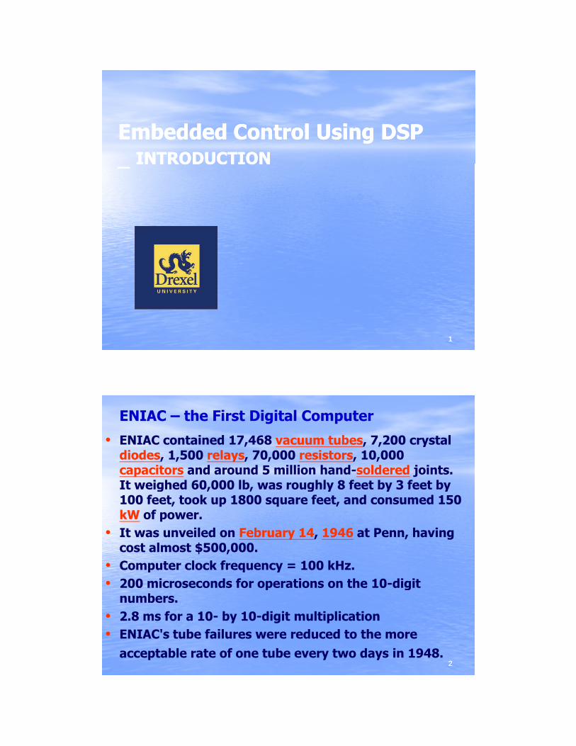
ENIAC – the First Digital Computer
• ENIAC contained 17,468 vacuum tubes, 7,200 crystal diodes, 1,500 relays, 70,000 resistors, 10,000 capacitors and around 5 million hand-soldered joints. It weighed 60,000 lb, was roughly 8 feet by 3 feet byIt weighed 60,000 lb, was roughly 8 feet by 3 feet by 100 feet, took up 1800 square feet, and consumed 150 kW of power.
• It was unveiled on February 14, 1946 at Penn, having cost almost $500,000.
• Computer clock frequency = 100 kHz.• 200 microseconds for operations on the 10 digit
22
• 200 microseconds for operations on the 10-digit numbers.
• 2.8 ms for a 10- by 10-digit multiplication• ENIAC's tube failures were reduced to the more
acceptable rate of one tube every two days in 1948.

ENIAC – Electronic Numerical Integrator And Calculator
33
MOS 6502 Chip – Apple II
• The chip is 40-pin DIP. An 8-bit processor with a 16-bit address bus.
• It costs $25 in 1975.• Comp ter clock freq enc 1 MH• Computer clock frequency = 1 MHz.• One 8-bit accumulator register (A), two 8-bit index
registers (X and Y), an 8-bit process status register (P), an 8-bit stack pointer (S), and a 16-bit program counter (PC).
44

F2812 Chip – 32-bit DSP
• The chip is 12mm x 12 mm x 1.4mm, and consumed 0.8 W of power.
• It costs $3 - $20.• Comp ter clock freq enc 150 MH• Computer clock frequency = 150 MHz.• 6.67 nanoseconds for operations on the 32-bit
numbers. • 6.67 ns for a 32-bit by 32-bit multiplication• Very reliable•• Much more functionsMuch more functions
55
Much more functionsMuch more functions
F28335 Chip – 32-bit Floating-point DSP
• The chip is 12mm x 12 mm x 1.4mm, and consumed 0.8 W of power.
• It costs $3 - $20.• Comp ter clock freq enc 150 MH• Computer clock frequency = 150 MHz.• 6.67 nanoseconds for operations on the 32-bit
numbers. • 6.67 ns for a 32-bit by 32-bit multiplication• Very reliable•• Much more functionsMuch more functions
66
Much more functionsMuch more functions
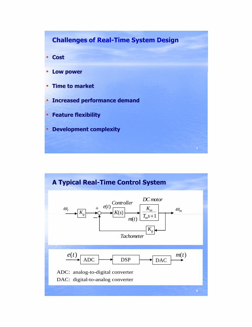
Challenges of Real-Time System Design
• Cost
• Low power• Low power
• Time to market
• Increased performance demand
fl ibili
77
• Feature flexibility
• Development complexity
A Typical Real-Time Control System
K
Tm
1Kg K s( )
DC motorController
+ ωmωre t( )
T sm +1
Kg
g K s( )−
Tachometer
m t( )
e t( ) m t( )
88
DSPADC e t( )
DACm t( )
ADC: analog-to-digital converterDAC: digital-to-analog converter

Input Signal Conditioning
• Types of signal conditioning– Amplification– Level translation– Filtering– Buffering - impedance translation
• Typical transducers that require conditioning– Microphones– Speed & Position Sensors
T t P S
99
– Temperature or Pressure Sensors– Imagers
Linear Circuits for Signal Conditioning
• Operational Amplifiers (BW<50 MHz)– General purpose building blocks– Used for low-speed applications
Key considerations are precision and DC– Key considerations are precision and DC performance
• High Speed Amplifiers (BW>50 MHz)– Used for high-speed signals such as imaging and
RF– Key considerations are: AC performance,
distortion BW
1010
distortion BW• Instrumentation Amplifiers
– Used specifically with low level signals where excellent noise rejection and precision are required
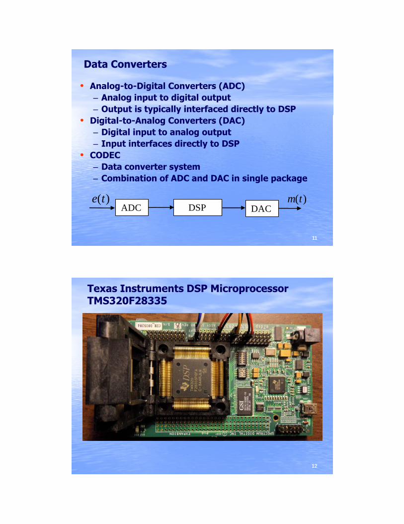
Data Converters
• Analog-to-Digital Converters (ADC)– Analog input to digital output– Output is typically interfaced directly to DSP
• Digital-to-Analog Converters (DAC)– Digital input to analog output– Input interfaces directly to DSP
• CODEC– Data converter system– Combination of ADC and DAC in single package
1111
Combination of ADC and DAC in single package
DSP ADC e t( )
DACm t( )
Texas Instruments DSP Microprocessor TMS320F28335
1212

TI DSP Microprocessor TMS320F28335• 150 MHz, 32-Bit CPU, Harvard Bus Architecture• Code-Efficient (in C/C++ and Assembly)• On-chip memory: 128K x 16 Flash, 5K x 16 ROM,
14K x 16 RAM Standard Math Tables14K x 16 RAM, Standard Math Tables• 256K x 16 Flash, 34K x 16 – 2 x 8 Channel Input
Multiplexer SARAM• 58 Peripheral Interrupts• Three 32-bit CPU Timers• 18 16-Bit PWM channels,
1313
18 16 Bit PWM channels, • 6 Capture Units (2 of them can be for QEP)• 16 12-Bit ADC channels• SPI, SCI, UART, eCAN, McBSP• 88 GPIO pins
Texas Instruments DSP Microprocessor TMS320F6416
1414

TI DSP Microprocessor TMS320F6416
• Highest-Performance Fixed-Point (DSPs)− Eight 32-Bit Instructions/Cycle− Up to 720MHz Clock Rates− Up to 28 Operations/Cycle− Up to 28 Operations/Cycle − Up to 5760 MIPS
• Advanced Very Long Instruction WordEight Highly Independent Functional Units:Six ALUs (32-/40-Bit), Each Supports Single 32-Bit, Dual 16-Bit, or Quad 8-Bit Arithmetic per Clock Cycle Two Multipliers Support Four 16 x 16-Bit Multiplies (32-Bit
1515
Two Multipliers Support Four 16 x 16 Bit Multiplies (32 Bit Results) per Clock Cycle or Eight 8 x 8-Bit Multiplies (16-Bit Results) per Clock Cycle64 32-Bit General-Purpose Registers
TI DSP Microprocessor TMS320F6416
• L1/L2 Memory Architecture• Two External Memory Interfaces (EMIFs)
One 64-Bit (EMIFA), One 16-Bit (EMIFB) Gl l I t f t A h M i (SRAM dGlueless Interface to Asynchronous Memories (SRAM and EPROM) and Synchronous Memories (SDRAM, SBSRAM, ZBT SRAM, and FIFO) 1280M-Byte Total Addressable External Memory Space
• Three Multichannel Buffered Serial Ports:− Serial-Peripheral-Interface (SPI)− Direct Interface to T1/E1, MVIP, SCSA Framers
1616
Direct Interface to T1/E1, MVIP, SCSA Framers− AC97 Interface
• 32-Bit/33-MHz, 3.3-V PCI Master/Slave Interface

Texas Instruments DSP Microprocessor TMS320F6713
1717
TI DSP Microprocessor TMS320F6713
• Highest-Performance Floating-Point (DSPs)− Eight 32-Bit Instructions/Cycle− 32/64-Bit Data Word− Up to 300MHz Clock Rates− Up to 300MHz Clock Rates− Up to 2400/1800 MIPS /MFLOPS− Rich Peripheral Set, Optimized for Audio− Highly Optimized C/C++ Compiler
• Advanced Very Long Instruction Word− Eight Independent Functional Units:− Two ALUs (Fixed-Point)
1818
− Two ALUs (Fixed-Point)− Four ALUs (Floating- and Fixed-Point)− Two Multipliers (Floating- and Fixed-Point)− Load-Store Architecture With 32 32-Bit General-Purpose
Registers
TI DSP Microprocessor TMS320F6713
• 32-Bit External Memory Interface (EMIF)− Glueless Interface to SRAM, EPROM, Flash, SBSRAM, and
SDRAM− 512M-Byte Total Addressable External Memory Space− 512M-Byte Total Addressable External Memory Space
• Two Multichannel Buffered Serial Ports:− Serial-Peripheral-Interface (SPI)− High-Speed TDM Interface− AC97 Interface
1919
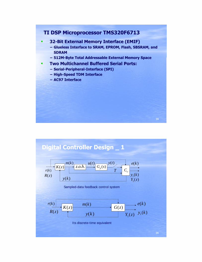
Digital Controller Design _ 1Digital Controller Design _ 1
( )m k
T( )K z
u t( ). . .z o h
( )r k( )pG s
( )y t
cC
( )e k
y k( )
T( )( )R z
c
1( )y k
1( )Y z
( )m k( )r k ( )e k
Sampled-data feedback control system
2020
1( )y ky k( )
( )m k( )K z
( )r k
( )R z
( )e k
1( )Y z
( )G z
Its discrete-time equivalent

Digital Controller Design _ 2Digital Controller Design _ 2
G sp ( )TE s( )R s( ) +
−
Y s( )E z( ) M z( )
digialcontroller plant
DAC( )K z
+
−
E z( ) M z( )
digialcontroller
G z( )R z( ) Y z( )( )K z
2121
Find so that the closedFind so that the closed--loop system loop system has a desired performance.has a desired performance.
( )K z
Digital Controller ImplementationDigital Controller Implementation
1 20 1 2
1 21 2
( )( )( ) 1
a a z a zM zK z
E z b z b z
− −
− −
+ += =+ +
)()()()(
)()()()(2
21
1
22
110
zXzbzXzbzEzX
zXzazXzazXazM
⋅−⋅−=
⋅+⋅+=−−
−−
)2()1()()( 210 −⋅+−⋅+= kxakxakxakm
1 2( ) 1E z b z b z+ +
2222
)2()1()()()()()()(
21
210
−⋅−−⋅−= kxbkxbkekx

Speed Control _ F2812Speed Control _ F2812
2323
Position Control _ F2812Position Control _ F2812
2424

Sinusoidal Tracking _ F2812Sinusoidal Tracking _ F2812
2525
DeDe--spin videospin video
2626

Autononous Tennis Ball HopperAutononous Tennis Ball Hopper__indoorsindoors
2727
Autononous Tennis Ball HopperAutononous Tennis Ball Hopper__outdoorsoutdoors
2828
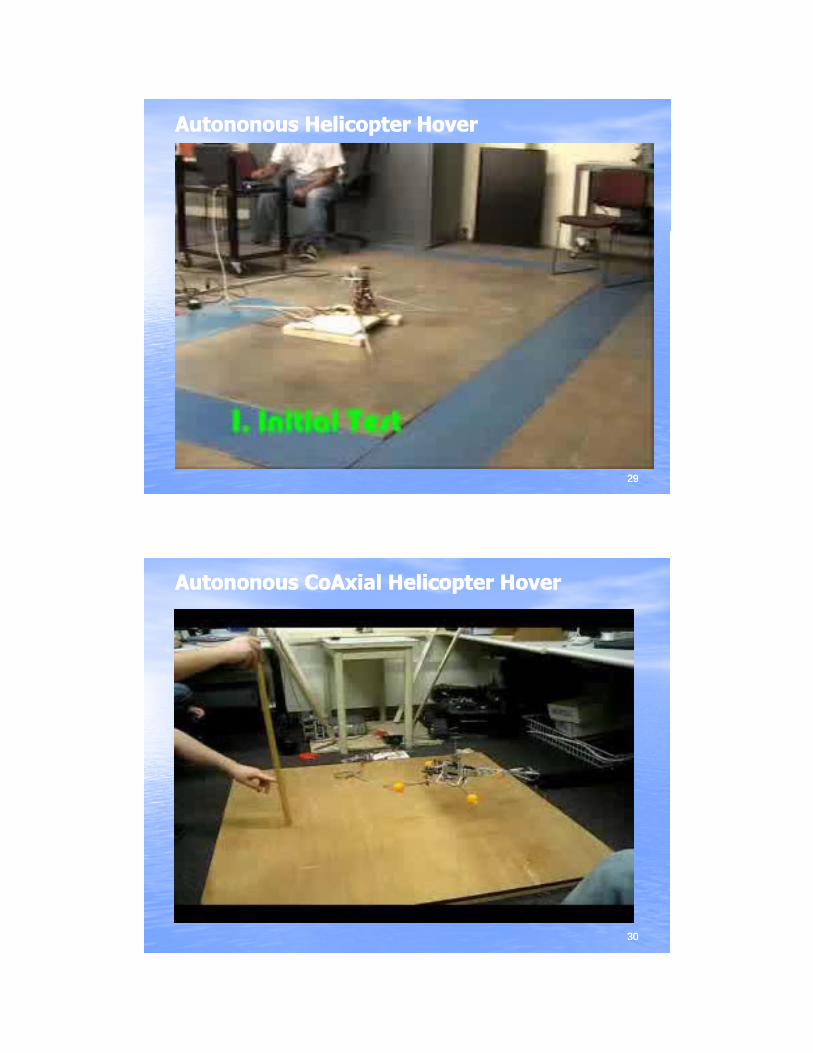
AutononousAutononous Helicopter HoverHelicopter Hover
2929
AutononousAutononous CoAxialCoAxial Helicopter HoverHelicopter Hover
3030

Inverted Pendulum:Inverted Pendulum: 180 deg swing up180 deg swing up
3131
Inverted Pendulum:Inverted Pendulum: 45 deg swing up45 deg swing up
3232

Inverted Pendulum:Inverted Pendulum: moderate disturbancemoderate disturbance
3333
Inverted Pendulum:Inverted Pendulum: violent disturbanceviolent disturbance
3434
Related Documents