How to install Installing the product Installation & safety instructions Mounting Boxes MK Elements Collection Installation Guide by Honeywell This product must be installed by a competent person (e.g. a qualified electrician) in accordance with these instructions and the appropriate current national wiring regulations (e.g. the IEE Wiring Regulations BS 7671). To prevent the risk of electrocution it is essential to disconnect the main electricity supply before commencing installation or maintenance work. Do not work on this product ‘live’. Do not use electric screwdrivers or power tools to tighten the product It is essential that all connections to the terminals are made as instructed, that cables are not stressed and all terminal screws are fully tightened. When earth terminals are present they must always be used. On wall mounted products ensure product is screwed securely to its mounting box before turning on the mains supply. To prevent fire hazard do not exceed the maximum rated current of the unit. The MK Elements Collection products consist of the main product module, complete with its support frame, plus a separate clip on frontplate. The product is mounted to the wall, after wiring, and the frontplate is clipped onto the frame. The frontplate is supplied separately to aid installation. Note: Switched Socket Outlets and Switches with built in LED locators and indicators must be removed from the circuit before insulation testing can be carried out. The MK Elements Collection wiring devices are designed to fit into folded metal boxes that comply with BS 4662. To ensure products can be correctly installed, the box must always be installed flush or sub flush to the surface to a maximum depth of 6mm. To ensure a safe installation, you must read all the installation & safety instructions on page 1 Steps for installation : 1. Ensure the depth of the back box is correct for the product and that it is fitted securely to the wall. 2. Install the cables in the normal way and, using the fixing screws supplied, mount the product, without the frontplate, to the wall. It is important the correct headed screws are used as any other may clash with the rear of the front plate. Switches incorporating a “LOOP” terminal are intended for connection of unused Neutral conductors only. 3. To optimise frontplate installation do not over tighten the screws. Adjust so the frame and module sit squarely on the wall. 4. Fit the frontplate as shown on page 4,5. Note: Care should be taken to ensure product features such as snap fits are not blocked during installation or decorating, preventing correct fitting of frontplates (for example plaster, tile grout, paint etc). When carrying out insulation resistance testing, first disconnect any product which features illumination. Failing to do this could damage the product and could also give spurious insulation readings. Fitting and removing the frontplate Fitting the frontplate 2 1 Removing the frontplate Connection Load/supply cables Strip back the sheath of the cable by the required amount. Strip back the insulation of the individual conductors by the required amount. Insert the conductors into the respective terminals. Where products are supplied with backed out terminal screws, do not loosen screws further. If the earth conductor is bare copper, ensure it is covered with a green/yellow sleeve, so it cannot touch live parts. Carefully push the wired product into the mounting box ensuring the cables are not trapped or pinched. Ensure all the terminal screws are tightened securely with a 4mm wide screwdriver. Pull on each cable to ensure the terminal screw has securely fixed the conductor. Data products in euro mounting frames Products operating at extra low voltage levels (<50V) must not be mounted in the same euro enclosures as equipment rated in excess of 50v (e.g. mains socket outlets). Carefully insert a 4mm screwdriver into the slots provided along the bottom edge of the frontplate Carefully twist the screwdriver and lift the frontplate away disengaging the snap fits 2 1 1 2 4 5 6 3 Recommended Mounting Box Minimum Depths : Socket outlets 35mm German style 2 pole + E Socket outlet 47mm (except K34384 : 35 mm) Connection units 35mm Plate switches 35mm Telephone, television and data outlets 35mm Grid switches 35mm High Current Switches 47mm Shaver supply units 47mm Rotary dimmer 35mm Some mounting boxes are fitted with additional threaded fixing lugs on the upper and lower edges. It may be necessary to bend these back into the box to ensure the frontplate sits flush with the mounting surface. The MK Elements Euro Module wiring devices range offers a variety of clip in modules, telephone, data connectors etc, providing the flexibility to customise a wiring device in the same enclosure and frontplate. Care must be taken to ensure that segregation is maintained between modules of different operating voltages in accordance with the current edition of the IEE Wiring Regulations (BS 7671). 1. Locate the top and bottom hooks on the back of the frontplate into the holes on the top and bottom of the module 2. Gently push along the top edge of the frontplate followed by the bottom edge. Note: Ensure the correct frontplate is fitted to the correct module or frame.

Elements Mechanical Switch Manual
Dec 24, 2015
Manual Switch
Welcome message from author
This document is posted to help you gain knowledge. Please leave a comment to let me know what you think about it! Share it to your friends and learn new things together.
Transcript
How to install
Installing the product
Installation & safety instructions
Mounting Boxes
MK Elements CollectionInstallation Guide
by Honeywell
This product must be installed by a competent person (e.g. a quali�ed electrician) in accordance with these instructions and the appropriate current national wiring regulations (e.g. the IEE Wiring Regulations BS 7671).To prevent the risk of electrocution it is essential to disconnect the main electricity supply before commencing installation or maintenance work. Do not work on this product ‘live’.Do not use electric screwdrivers or power tools to tighten the productIt is essential that all connections to the terminals are made as instructed, that cables are not stressed and all terminal screws are fully tightened.When earth terminals are present they must always be used. On wall mounted products ensure product is screwed securely to its mounting box before turning on the mains supply.To prevent �re hazard do not exceed the maximum rated current of the unit.The MK Elements Collection products consist of the main product module, complete with its support frame, plus a separate clip on frontplate. The product is mounted to the wall, after wiring, and the frontplate is clipped onto the frame.The frontplate is supplied separately to aid installation.
Note: Switched Socket Outlets and Switches with built in LED locators and indicators must be removed from the circuit before insulation testing can be carried out.
The MK Elements Collection wiring devices are designed to �t into folded metal boxes that comply with BS 4662. To ensure products can be correctly installed, the box must always be installed �ush or sub �ush to the surface to a maximum depth of 6mm.
To ensure a safe installation, you must read all the installation & safety instructions on page 1
Steps for installation :
1. Ensure the depth of the back box is correct for the product and that it is �tted securely to the wall.
2. Install the cables in the normal way and, using the �xing screws supplied, mount the product, without the frontplate, to the wall. It is important the correct headed screws are used as any other may clash with the rear of the front plate. Switches incorporating a “LOOP” terminal are intended for connection of unused Neutral conductors only.
3. To optimise frontplate installation do not over tighten the screws. Adjust so the frame and module sit squarely on the wall.
4. Fit the frontplate as shown on page 4,5.
Note:Care should be taken to ensure product features such as snap �ts are not blocked during installation or decorating, preventing correct �tting of frontplates (for example plaster, tile grout, paint etc).When carrying out insulation resistance testing, �rst disconnect any product which features illumination. Failing to do this could damage the product and could also give spurious insulation readings.
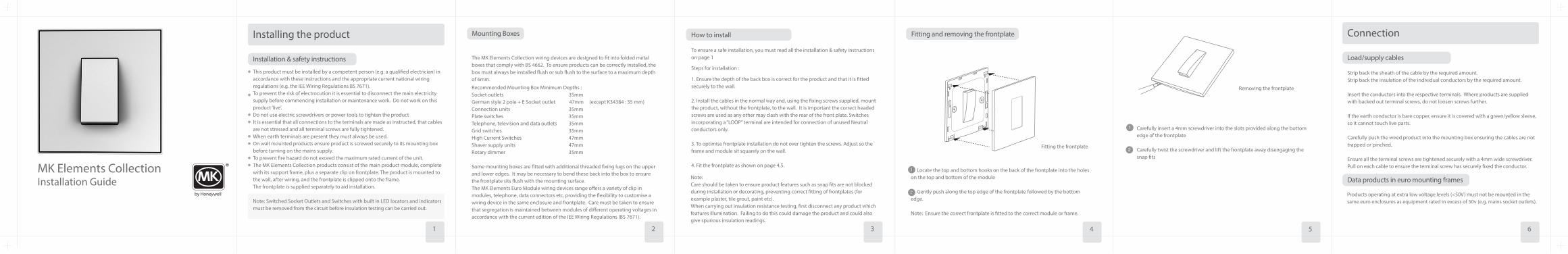
Fitting and removing the frontplate
Fitting the frontplate
2
1
Removing the frontplate
Connection
Load/supply cables
Strip back the sheath of the cable by the required amount.Strip back the insulation of the individual conductors by the required amount.
Insert the conductors into the respective terminals. Where products are supplied with backed out terminal screws, do not loosen screws further.
If the earth conductor is bare copper, ensure it is covered with a green/yellow sleeve, so it cannot touch live parts.
Carefully push the wired product into the mounting box ensuring the cables are not trapped or pinched.
Ensure all the terminal screws are tightened securely with a 4mm wide screwdriver. Pull on each cable to ensure the terminal screw has securely �xed the conductor.
Data products in euro mounting frames
Products operating at extra low voltage levels (<50V) must not be mounted in the same euro enclosures as equipment rated in excess of 50v (e.g. mains socket outlets).
Carefully insert a 4mm screwdriver into the slots provided along the bottom edge of the frontplate
Carefully twist the screwdriver and lift the frontplate away disengaging the snap �ts
2
1
1 2 4 5 63
Recommended Mounting Box Minimum Depths :Socket outlets 35mmGerman style 2 pole + E Socket outlet 47mm (except K34384 : 35 mm)Connection units 35mmPlate switches 35mmTelephone, television and data outlets 35mmGrid switches 35mmHigh Current Switches 47mmShaver supply units 47mmRotary dimmer 35mm
Some mounting boxes are �tted with additional threaded �xing lugs on the upper and lower edges. It may be necessary to bend these back into the box to ensure the frontplate sits �ush with the mounting surface.The MK Elements Euro Module wiring devices range o�ers a variety of clip in modules, telephone, data connectors etc, providing the �exibility to customise a wiring device in the same enclosure and frontplate. Care must be taken to ensure that segregation is maintained between modules of di�erent operating voltages in accordance with the current edition of the IEE Wiring Regulations (BS 7671).
1. Locate the top and bottom hooks on the back of the frontplate into the holes on the top and bottom of the module 2. Gently push along the top edge of the frontplate followed by the bottom edge. Note: Ensure the correct frontplate is �tted to the correct module or frame.
Warranty
Technical Help
Tel: Fax: [email protected]
Technical Help
Tel: Fax: [email protected]
+44 (0)1268 563720+44 (0)1268 563064+44 (0)1268 563720+44 (0)1268 563064
Customer Service
Tel: +44 (0) 1268 563000Fax: +44 (0) 1268 563405Fax: +44 (0) 1268 563365 (International)
Customer Service
Tel: +44 (0) 1268 563000Fax: +44 (0) 1268 563405Fax: +44 (0) 1268 563365 (International)
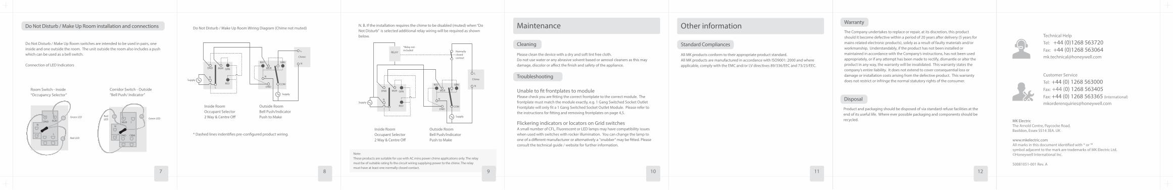
Do Not Disturb / Make Up Room installation and connections
Do Not Disturb / Make Up Room switches are intended to be used in pairs, one inside and one outside the room. The unit outside the room also includes a push which can be used as a bell switch.
Connection of LED Indicators
Maintenance
Cleaning
Please clean the device with a dry and soft lint free cloth. Do not use water or any abrasive solvent based or aerosol cleaners as this may damage, discolor or a�ect the �nish and safety of the appliance.
Troubleshooting
Unable to �t frontplates to modulePlease check you are �tting the correct frontplate to the correct module. The frontplate must match the module exactly, e.g. 1 Gang Switched Socket Outlet Frontplate will only �t a 1 Gang Switched Socket Outlet Module. Please refer to the instructions for �tting and removing frontplates on page 4,5.
Flickering indicators or locators on Grid switches A small number of CFL, Fluorescent or LED lamps may have compatibility issues when used with switches with rocker illumination. You can change the lamp to one of a di�erent manufacturer or alternatively a "snubber" may be �tted. Please consult the technical guide / website for further information.
Other information
Standard Compliances
All MK products conform to their appropriate product standard.All MK products are manufactured in accordance with ISO9001: 2000 and where applicable, comply with the EMC and/or LV directives 89/336/EEC and 73/23/EEC.
Disposal
Product and packaging should be disposed of via standard refuse facilities at the end of its useful life. Where ever possible packaging and components should be recycled.
The Company undertakes to replace or repair, at its discretion, this product should it become defective within a period of 20 years after delivery (5 years for mains related electronic products), solely as a result of faulty materials and/or workmanship. Understandably, if the product has not been installed or maintained in accordance with the Company’s instructions, has not been used appropriately, or if any attempt has been made to rectify, dismantle or alter the product in any way, the warranty will be invalidated. This warranty states the company’s entire liability. It does not extend to cover consequential loss or damage or installation costs arising from the defective product. This warranty does not restrict or infringe the normal statutory rights of the consumer.
DND NURGreen LED
Red LED
L
N
Room Switch - Inside“Occupancy Selector”
Do Not Disturb / Make Up Room Wiring Diagram (Chime not muted) N. B. If the installation requires the chime to be disabled (muted) when “Do Not Disturb” is selected additional relay wiring will be required as shown below.
DND COM
1MURGreen LED
RedLED
L
N
Corridor Switch - Outside“Bell Push/ Indicator”
L
NGRN
DND
DND MUR GRN
COM
Supply
SupplyNN
L
MUR
RED
RED
1
Chime
Inside RoomOccupant Selector2 Way & Centre O�
* Dashed lines indenti�es pre-con�gured product wiring.
Outside RoomBell Push/IndicatorPush to Make
Inside RoomOccupant Selector2 Way & Centre O�
Outside RoomBell Push/IndicatorPush to Make
Chime
L
NGRN
DND
DND MUR GRN
COM
Supply
SupplyNN
MUR
RED
REDL
1
RELAY
*Relay notincluded Normally
closedcontact
www.mkelectric.comAll marks in this document identi�ed with ® or ™ symbol adjacent to the mark are trademarks of MK Electric Ltd.©Honeywell International Inc.
50081051-001 Rev. A
www.mkelectric.comAll marks in this document identi�ed with ® or ™ symbol adjacent to the mark are trademarks of MK Electric Ltd.©Honeywell International Inc.
50081051-001 Rev. A
MK ElectricThe Arnold Centre, Paycocke Road, Basildon, Essex SS14 3EA. UK
Note:These products are suitable for use with AC mins power chime applications only. The relay must be of suitable rating fo the circuit wiring supplying power to the chime. The relay must have at least one normally closed contact.
7 8 9 1110 12
Related Documents