Electronically Switchable Sham Transcranial Magnetic Stimulation (TMS) System Fumiko Hoeft 1,2 *, Daw-An Wu 2,3 , Arvel Hernandez 1 , Gary H. Glover 4 , Shinsuke Shimojo 2 1 Center for Interdisciplinary Brain Sciences Research (CIBSR), Stanford University School of Medicine, Palo Alto, California, United States of America, 2 Computation and Neural Systems and Division of Biology, California Institute of Technology, Pasadena, California, United States of America, 3 Department of Psychology, Harvard University, Cambridge, Massachusetts, United States of America, 4 Department of Radiology, Stanford University School of Medicine, Palo Alto, California, United States of America Abstract Transcranial magnetic stimulation (TMS) is increasingly being used to demonstrate the causal links between brain and behavior in humans. Further, extensive clinical trials are being conducted to investigate the therapeutic role of TMS in disorders such as depression. Because TMS causes strong peripheral effects such as auditory clicks and muscle twitches, experimental artifacts such as subject bias and placebo effect are clear concerns. Several sham TMS methods have been developed, but none of the techniques allows one to intermix real and sham TMS on a trial-by-trial basis in a double-blind manner. We have developed an attachment that allows fast, automated switching between Standard TMS and two types of control TMS (Sham and Reverse) without movement of the coil or reconfiguration of the setup. We validate the setup by performing mathematical modeling, search-coil and physiological measurements. To see if the stimulus conditions can be blinded, we conduct perceptual discrimination and sensory perception studies. We verify that the physical properties of the stimulus are appropriate, and that successive stimuli do not contaminate each other. We find that the threshold for motor activation is significantly higher for Reversed than for Standard stimulation, and that Sham stimulation entirely fails to activate muscle potentials. Subjects and experimenters perform poorly at discriminating between Sham and Standard TMS with a figure-of-eight coil, and between Reverse and Standard TMS with a circular coil. Our results raise the possibility of utilizing this technique for a wide range of applications. Citation: Hoeft F, Wu D-A, Hernandez A, Glover GH, Shimojo S (2008) Electronically Switchable Sham Transcranial Magnetic Stimulation (TMS) System. PLoS ONE 3(4): e1923. doi:10.1371/journal.pone.0001923 Editor: Edwin Robertson, Harvard Medical School, United States of America Received December 2, 2007; Accepted February 29, 2008; Published April 9, 2008 Copyright: ß 2008 Hoeft et al. This is an open-access article distributed under the terms of the Creative Commons Attribution License, which permits unrestricted use, distribution, and reproduction in any medium, provided the original author and source are credited. Funding: This study was funded by the National Science Foundation under BCS-0305276 and BCS-0305866. The sponsors did not play any role in the study besides providing funding. Competing Interests: The authors have declared that no competing interests exist. * E-mail: [email protected] Introduction Transcranial magnetic stimulation (TMS) is an increasingly popular neuroscience tool due to its unique ability to noninvasively alter neural activity in targeted regions of the brain [1]. Since its introduction in 1985 by Barker and colleagues [2], TMS has been used to probe motor cortex excitability [3–6], map motor and cognitive functions [7,8], study anatomical and functional connectivity [8,9], and modulate brain function with therapeutic aims [6,10,11]. TMS uses a time-varying magnetic field to induce an electrical current through the skull, in a spatially restricted region of the cerebral cortex. The induction of electrical current occurs with minimal attenuation of the magnetic field. Significant currents can be induced without having to apply substantial voltages across the skull, minimizing the activation of pain fibers and pain sensation. The advantage of TMS is also in its temporal (sub-millisecond) and spatial (sub-centimeter) resolution. Two configurations of TMS coils are commonly used in scientific and clinical research. The figure-of-eight coil (also known as butterfly or double coils) is the most commonly used configuration owing to its superior spatial specificity. The circular coil is less used because while it offers more powerful stimulation and the opportunity to target both motor cortices at the same time with relatively little worry about specific placement or constant positioning, it is also less focused. It has been used in clinical trials that targets large regions of the brain, such as investigations of Parkinson’s disease and epilepsy [12] and motor physiology studies [13]. Its specificity can also be improved when applied to brain regions where the preferred current direction is known, such as the motor and visual cortices [13–15]. As with any experimental technique, TMS has its pitfalls [16]. Specifically, TMS is accompanied by a number of ancillary effects. The coil emits clicking sounds with each stimulation, and can also stimulate nearby peripheral nerves and muscles. Depending on the location and strength of TMS, this may result in sensations ranging from a light tapping on the scalp to uncomfortable muscle twitches in the face, neck, or shoulders. These sensations can nonspecifically interfere with task performance via distraction or subject biasing, contaminating the results. In clinical research, placebo effects are known to be high [17,18], especially with medical devices where there is significant patient-investigator contact [19]. To separate the effects of brain stimulation from those arising from the above artifacts, experimenters can compare results with control conditions in which they either apply sham stimulation or apply real stimulation to a control brain region. These two methods are complementary to one another; one may not be necessary in some studies, and in other studies, stimulation of control brain regions methods may still be necessary in addition to PLoS ONE | www.plosone.org 1 April 2008 | Volume 3 | Issue 4 | e1923

Welcome message from author
This document is posted to help you gain knowledge. Please leave a comment to let me know what you think about it! Share it to your friends and learn new things together.
Transcript
Electronically Switchable Sham Transcranial MagneticStimulation (TMS) SystemFumiko Hoeft1,2*, Daw-An Wu2,3, Arvel Hernandez1, Gary H. Glover4, Shinsuke Shimojo2
1 Center for Interdisciplinary Brain Sciences Research (CIBSR), Stanford University School of Medicine, Palo Alto, California, United States of America, 2 Computation and
Neural Systems and Division of Biology, California Institute of Technology, Pasadena, California, United States of America, 3 Department of Psychology, Harvard University,
Cambridge, Massachusetts, United States of America, 4 Department of Radiology, Stanford University School of Medicine, Palo Alto, California, United States of America
Abstract
Transcranial magnetic stimulation (TMS) is increasingly being used to demonstrate the causal links between brain andbehavior in humans. Further, extensive clinical trials are being conducted to investigate the therapeutic role of TMS indisorders such as depression. Because TMS causes strong peripheral effects such as auditory clicks and muscle twitches,experimental artifacts such as subject bias and placebo effect are clear concerns. Several sham TMS methods have beendeveloped, but none of the techniques allows one to intermix real and sham TMS on a trial-by-trial basis in a double-blindmanner. We have developed an attachment that allows fast, automated switching between Standard TMS and two types ofcontrol TMS (Sham and Reverse) without movement of the coil or reconfiguration of the setup. We validate the setup byperforming mathematical modeling, search-coil and physiological measurements. To see if the stimulus conditions can beblinded, we conduct perceptual discrimination and sensory perception studies. We verify that the physical properties of thestimulus are appropriate, and that successive stimuli do not contaminate each other. We find that the threshold for motoractivation is significantly higher for Reversed than for Standard stimulation, and that Sham stimulation entirely fails toactivate muscle potentials. Subjects and experimenters perform poorly at discriminating between Sham and Standard TMSwith a figure-of-eight coil, and between Reverse and Standard TMS with a circular coil. Our results raise the possibility ofutilizing this technique for a wide range of applications.
Citation: Hoeft F, Wu D-A, Hernandez A, Glover GH, Shimojo S (2008) Electronically Switchable Sham Transcranial Magnetic Stimulation (TMS) System. PLoSONE 3(4): e1923. doi:10.1371/journal.pone.0001923
Editor: Edwin Robertson, Harvard Medical School, United States of America
Received December 2, 2007; Accepted February 29, 2008; Published April 9, 2008
Copyright: � 2008 Hoeft et al. This is an open-access article distributed under the terms of the Creative Commons Attribution License, which permitsunrestricted use, distribution, and reproduction in any medium, provided the original author and source are credited.
Funding: This study was funded by the National Science Foundation under BCS-0305276 and BCS-0305866. The sponsors did not play any role in the studybesides providing funding.
Competing Interests: The authors have declared that no competing interests exist.
* E-mail: [email protected]
Introduction
Transcranial magnetic stimulation (TMS) is an increasingly
popular neuroscience tool due to its unique ability to noninvasively
alter neural activity in targeted regions of the brain [1]. Since its
introduction in 1985 by Barker and colleagues [2], TMS has been
used to probe motor cortex excitability [3–6], map motor and
cognitive functions [7,8], study anatomical and functional
connectivity [8,9], and modulate brain function with therapeutic
aims [6,10,11].
TMS uses a time-varying magnetic field to induce an electrical
current through the skull, in a spatially restricted region of the
cerebral cortex. The induction of electrical current occurs with
minimal attenuation of the magnetic field. Significant currents can
be induced without having to apply substantial voltages across the
skull, minimizing the activation of pain fibers and pain sensation.
The advantage of TMS is also in its temporal (sub-millisecond)
and spatial (sub-centimeter) resolution.
Two configurations of TMS coils are commonly used in
scientific and clinical research. The figure-of-eight coil (also known
as butterfly or double coils) is the most commonly used
configuration owing to its superior spatial specificity. The circular
coil is less used because while it offers more powerful stimulation
and the opportunity to target both motor cortices at the same time
with relatively little worry about specific placement or constant
positioning, it is also less focused. It has been used in clinical trials
that targets large regions of the brain, such as investigations of
Parkinson’s disease and epilepsy [12] and motor physiology studies
[13]. Its specificity can also be improved when applied to brain
regions where the preferred current direction is known, such as the
motor and visual cortices [13–15].
As with any experimental technique, TMS has its pitfalls [16].
Specifically, TMS is accompanied by a number of ancillary effects.
The coil emits clicking sounds with each stimulation, and can also
stimulate nearby peripheral nerves and muscles. Depending on the
location and strength of TMS, this may result in sensations
ranging from a light tapping on the scalp to uncomfortable muscle
twitches in the face, neck, or shoulders. These sensations can
nonspecifically interfere with task performance via distraction or
subject biasing, contaminating the results. In clinical research,
placebo effects are known to be high [17,18], especially with
medical devices where there is significant patient-investigator
contact [19].
To separate the effects of brain stimulation from those arising
from the above artifacts, experimenters can compare results with
control conditions in which they either apply sham stimulation or
apply real stimulation to a control brain region. These two
methods are complementary to one another; one may not be
necessary in some studies, and in other studies, stimulation of
control brain regions methods may still be necessary in addition to
PLoS ONE | www.plosone.org 1 April 2008 | Volume 3 | Issue 4 | e1923
sham TMS (to show specificity of the brain region of interest).
Ideally, the experimental and control conditions should differ only
by the way in which brain is stimulated, while producing auditory
and tactile artifacts that are not easily distinguishable from real
stimulation. See Supporting Information Text S1 for detailed
discussion about different types of control (including sham)
conditions that are available. Furthermore, the conditions should
be easily interleaved to allow within-subject comparisons and
intermix various conditions trial-by-trial.
The goal of this study was to develop and fully validate a
method of delivering several control TMS conditions. Two coils
were fabricated; a figure-of-eight coil (Fig8) that has loops of coils
in each of the two wings that are driven separately, and a circular
coil (Circ) that has two sets of coils stacked on top of another that
are also driven separately. An attachment allows the delivery of
three types of stimuli in an automated, interleaved manner without
switching or moving the coil (single-trial sham TMS). 1) Standard
stimuli are delivered when current direction in both loops matches
that of the standard coils. 2) Sham stimuli are delivered when current
direction in one of the two loops is backwards. 3) Reversed stimuli
are delivered when current direction in both loops is backwards.
Reversed stimuli reproduce the fields created by coil-flipping, which
can be used to increase activation thresholds over brain areas where
the preferred stimulus orientation is known, such as motor [20–23],
visual [24] and prefrontal cortices [25]. In the case of motor and
visual areas, these can also be used to preferentially stimulate either
hemisphere from a single coil location.
We extend upon Ruohonen et al.’s design of a sham Fig8 coil
[26]. We add independent control of current direction in both coil
loops so that reverse stimulation is possible in addition to sham and
standard stimulation. Further, automated electronic switching of
stimulus types can be done within 3 ms with a solid state switch
known as thyristors, and we apply the design to both Fig8 and Circ
coils. In addition, one can adjust stimulation intensity of each
current to achieve complete cancellation of the induced fields (with
circular coils, since there is some distance between the two loops of
coils, the stimulus intensity necessary to achieve complete
cancellation for each loop is different). To enhance the
applicability of the design, we implement it in an attachment to
Magstim single- and dual-pulse setups, which are in common use
in research and clinical settings.
Four types of experiments were performed to validate the
Standard, Reversed and Sham TMS delivered from the Fig8 and
Circ coils. First, in order to characterize physical properties of the
stimuli such as electro-motive force (EMF), we performed
mathematical modeling and actual measurements using a
search-coil. This included both measurements of single pulses
and of successive pulses to ensure that stimulus properties were not
contaminated by prior stimuli via residual states in the circuitry.
Second, we measured the physiological effects of the stimulus types
by comparing thresholds for eliciting motor evoked-potentials
(MEPs) when stimulating primary motor cortex. Third, we tested
the perceptual effects of the different pulses by testing whether
subjects and experienced investigators could differentiate Sham
stimuli, and if so whether Standard and Reversed could be
differentiated (which may serve as another form of sham TMS).
Finally, sound pressure level (SPL), subjective loudness and pain
intensity were measured to further characterize their effects on the
subjects.
Results
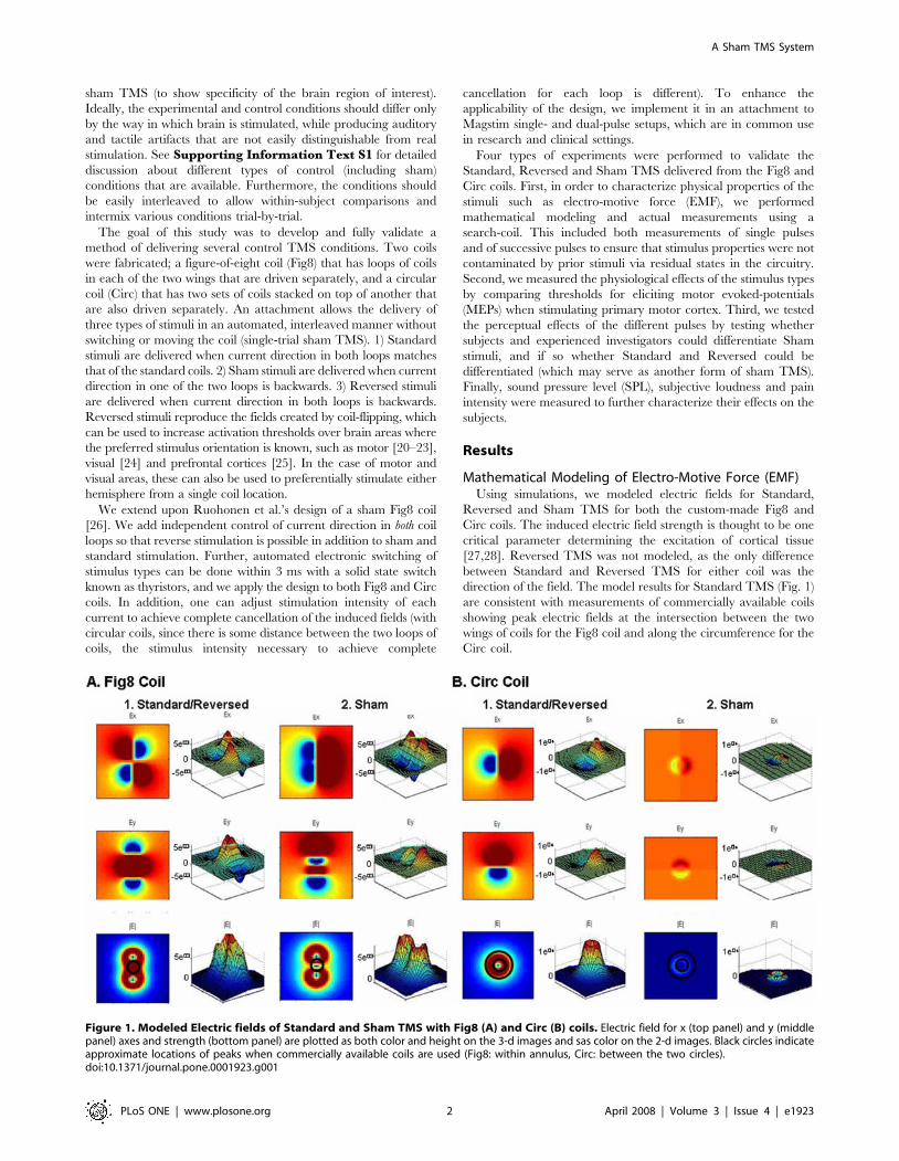
Mathematical Modeling of Electro-Motive Force (EMF)Using simulations, we modeled electric fields for Standard,
Reversed and Sham TMS for both the custom-made Fig8 and
Circ coils. The induced electric field strength is thought to be one
critical parameter determining the excitation of cortical tissue
[27,28]. Reversed TMS was not modeled, as the only difference
between Standard and Reversed TMS for either coil was the
direction of the field. The model results for Standard TMS (Fig. 1)
are consistent with measurements of commercially available coils
showing peak electric fields at the intersection between the two
wings of coils for the Fig8 coil and along the circumference for the
Circ coil.
Figure 1. Modeled Electric fields of Standard and Sham TMS with Fig8 (A) and Circ (B) coils. Electric field for x (top panel) and y (middlepanel) axes and strength (bottom panel) are plotted as both color and height on the 3-d images and sas color on the 2-d images. Black circles indicateapproximate locations of peaks when commercially available coils are used (Fig8: within annulus, Circ: between the two circles).doi:10.1371/journal.pone.0001923.g001
A Sham TMS System
PLoS ONE | www.plosone.org 2 April 2008 | Volume 3 | Issue 4 | e1923
When Sham TMS is applied through the Fig8 coil, the central
peak is eliminated, but the smaller surrounding peaks remain
similar in absolute magnitude. In the Circ coil, the fields are
uniformly and drastically diminished in strength.
Search Coil Measurements of EMFIn the second series of experiments, we measured EMF
(proportional to the current which would be induced in the tissue)
of various TMS pulses applied to a search coil. First we compared
EMF amplitude between Standard, Reversed and Sham TMS
through the Fig8 and Circ coils using independent t-tests. There
were no significant differences in EMF between Standard and
Reversed (Fig8: t(38) = 0.12, p = 0.91; Circ: t(38) = 0.17, p = 0.87).
There were however, significant differences in EMF between
Standard (or Reversed) and Sham (Fig8: t(38) = 29.2, p,0.001;
Circ: t(38) = 15.5, p,0.001).
Next, we compared the EMF amplitudes of two TMS pulses
delivered at an ISI of 10 ms to investigate whether there were any
residual effects in the electronics that would cause contamination
of the second pulse at this short inter-trial interval (ISI). When we
examined EMF induced by commercially available Fig8 and Circ
coils, we found no effect of the 1st pulse on the 2nd pulse, i.e., there
were no significant differences between the 1st and 2nd EMF (Fig8:
t(38) = 0.03, p = 0.98; Circ: t(38) = 0.10, p = 0.92; Fig. 2A top left
panel). When two consecutive Standard (or Reversed) TMS were
delivered using custom-made coils, both Fig8 and Circ coils also
showed no significant differences in EMF (Fig8: t(38) = 0.10,
p = 0.92; Circ: t(38) = 0.23, p = 0.82; Fig. 2A top right panel).
When Reversed was delivered after Standard TMS (or Standard
after Reversed), similarly there was no significant effect of the 1st
pulse on the 2nd (Fig8: t(38) = 0.14, p = 0.89; Circ: t(38) = 0.02,
p = 0.97; Fig. 2A bottom left panel). Finally, we tested the effect of
Standard or Reversed TMS (1st pulse) on Sham TMS (2nd pulse).
There were no significant differences between EMF of single-pulse
Sham TMS and the 2nd pulse Sham TMS (Fig8: t(38) = 0.39,
p = 0.70; Circ: t(38) = 0.28, p = 0.78; Fig. 2A bottom right panel). In
sum, no significant interactions were found in any of the
combinations tested.
We then measured the decay of stimulation with increased
distance by placing the search coil at distances from 10 to 50 mm
away from the custom-made Fig8 and Circ coils. There was a
monotonic decrease in EMF for Standard (and Reversed) and
Sham TMS as the distance increased (Fig. 2B-1). For both the Fig8
and Circ coils, EMF amplitude measures using one-way repeated
measures analysis of variance (ANOVA) showed significant main
effects of distance (10 30, 50 mm) for all TMS type (Standard/
Reversed, Sham) and coils (Fig8, Circ) (Fig8-Standard/Reversed:
F(2, 57) = 104.2, p,0.001; Fig8-Sham: F(2, 57) = 1139.5, p,0.001;
Circ-Standard/Reversed: F(2, 57) = 22510.0, p,0.001; Circ-Sham:
F(2, 57) = 7441.6, p,0.001).
In addition, we measured the effect of stimulation intensity (10
to 50% of maximum output) with the custom-made Fig8 and Circ
coils. There was a monotonic decrease in EMF for both Standard
(and Reversed) and Sham TMS as the stimulation intensity
decreased (Fig. 2B-2). For both the Fig8 and Circ coils, using one-
way repeated measures ANOVA, EMF amplitude showed
significant main effects of intensity (10, 30, 50%) for all TMS
type (Standard/Reversed, Sham) and coils (Fig8, Circ) except for
Sham TMS using the Fir8 coil (Fig8-Standard/Reversed:
F(2,57) = = 10.1, p,0.001; Fig8-Sham: F(2,57) = 1.42, p = 0.25;
Circ-Standard/Reversed: F(2,57) = 15652.4, p,0.001; Circ-Sham:
F(2,57) = 3002.9, p,0.001).
The results thus far show that EMF amplitude of Sham
compared to Standard or Reversed TMS is significantly reduced.
Further, Standard TMS and Reversed TMS have similar
characteristics with the only difference being their polarities.
Motor PhysiologyIn the third series of experiments, we performed motor
physiological experiments to compare the levels of brain
stimulation induced by Standard, Reversed and Sham TMS
through the Fig8 and Circ coils. The coils were placed in an
optimal orientation for Standard TMS (i.e., current flowing in the
medial-anterior direction, which is in the perpendicular orienta-
tion to the central sulcus [20,29]).
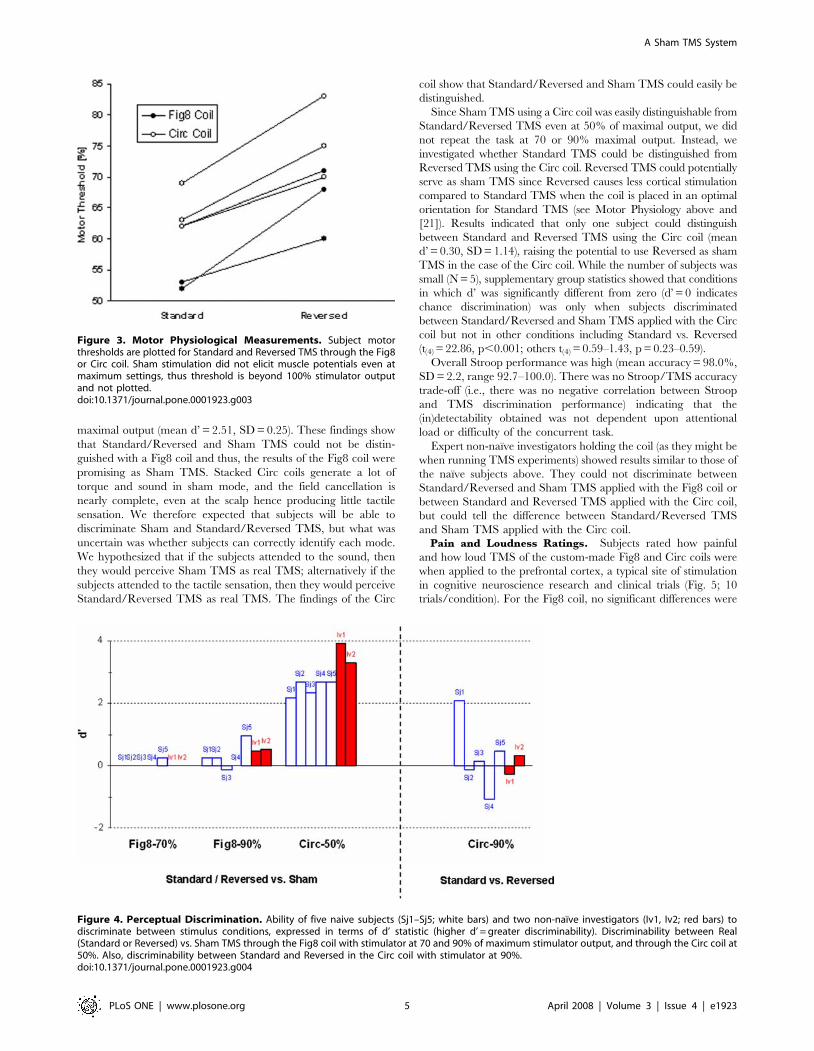
Comparing Standard and Reversed TMS (Fig. 3), the motor
threshold was higher for Reversed TMS (Fig8 coil: mean
difference = 10.7, standard deviation (SD) = 4.7; Circ coil: mean
difference = 11.3, SD = 3.1). This is consistent with the past
literature indicating that when a coil is rotated by 180 degrees,
that the motor threshold decreases by approximately 10.7% units
of maximal stimulator output [21].
With Sham TMS, no MEPs could be detected even with
maximal output, (and hence there was no measurable motor
threshold) for neither the Fig8 nor the Circ coil.
Perceptual DiscriminationIn the next series of experiments, we tested whether naı̈ve
subjects and expert investigators could tell whether they received
or applied Standard, Reversed or Sham TMS using the custom-
made Fig8 and Circ coils. In order to simulate a realistic situation
of a TMS experiment, naı̈ve subjects performed a Stroop task
(naming colors of words as accurately and as fast as possible where
the words themselves were names of colors incongruent to the
color of the words) while they discriminated between TMS types.
While we intended this experiment for situations where single-trial
TMS will be applied, this is not necessarily a realistic environment
for some applications such as those intended for treatment, as
subjects often do not perform any task while being stimulated.
Experienced TMS researchers held the coil in their hand applying
TMS and also attempted to discriminate between TMS types.
First, naı̈ve subjects received 12 pulses of Standard, Reversed
and Sham TMS and were then asked whether they had noticed
different kinds of TMS pulses using the Fig8 coil. Since this was a
debriefing experiment, we could only perform this test once for
each subject.
None of the subjects were able to tell that there were different
types of TMS intermixed using the Fig8 coil. When the subjects
were specifically prompted to describe differences in strength or
sensation from one pulse to another, none of the descriptions
reflected the experimental manipulation. The following are sample
impressions from subjects: ‘I didn’t notice anything different about
the pulses… maybe intervals were random?’, ‘Did the intensity get
stronger as the trials proceeded?’ (Intensity did not get stronger as
trials proceeded), ‘I don’t know, but I thought it switched sides, but
only once.’ (TMS pulse did not switch sides).
Prior to the next experiment, subjects went through a training
period in which we administered several pulses of each type to
serve as exemplars for Standard, Reversed and Sham TMS
(approximately 5 pulses each). In the main experiment, subjects
were asked to identify whether they received 1) a Standard or
Reversed TMS, or 2) Sham TMS. As can be seen in Fig. 4, the d-
prime (d’, discriminability) values indicated that subjects could not
tell whether they were receiving Standard/Reversed or Sham
TMS with the Fig8 coil even when the stimulus intensity was set
high at 70 or 90% (70%: mean d’ = 0.05, SD = 0.12; 90%: mean
d’ = 0.27, SD = 0.42). However, all subjects could make the
discrimination when a Circ coil was used, even at 50% of
A Sham TMS System
PLoS ONE | www.plosone.org 3 April 2008 | Volume 3 | Issue 4 | e1923
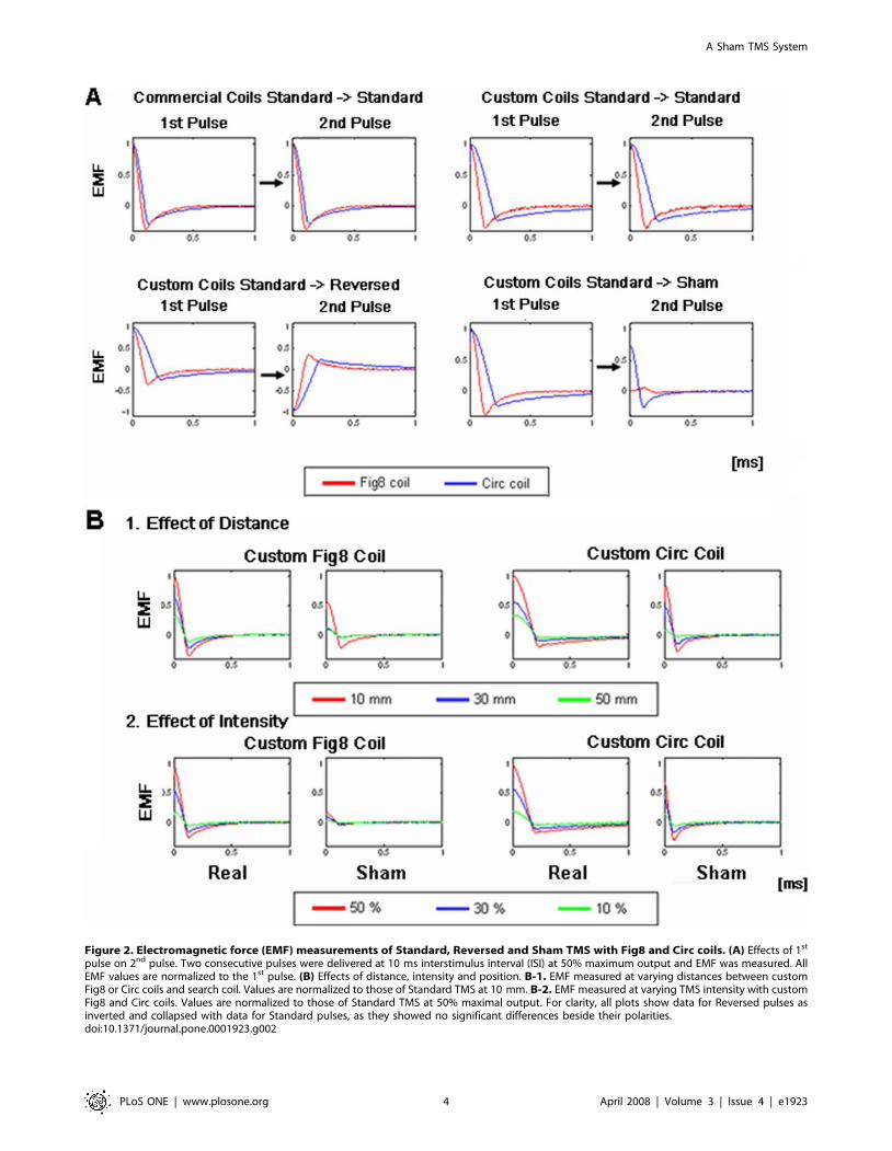
Figure 2. Electromagnetic force (EMF) measurements of Standard, Reversed and Sham TMS with Fig8 and Circ coils. (A) Effects of 1st
pulse on 2nd pulse. Two consecutive pulses were delivered at 10 ms interstimulus interval (ISI) at 50% maximum output and EMF was measured. AllEMF values are normalized to the 1st pulse. (B) Effects of distance, intensity and position. B-1. EMF measured at varying distances between customFig8 or Circ coils and search coil. Values are normalized to those of Standard TMS at 10 mm. B-2. EMF measured at varying TMS intensity with customFig8 and Circ coils. Values are normalized to those of Standard TMS at 50% maximal output. For clarity, all plots show data for Reversed pulses asinverted and collapsed with data for Standard pulses, as they showed no significant differences beside their polarities.doi:10.1371/journal.pone.0001923.g002
A Sham TMS System
PLoS ONE | www.plosone.org 4 April 2008 | Volume 3 | Issue 4 | e1923
maximal output (mean d’ = 2.51, SD = 0.25). These findings show
that Standard/Reversed and Sham TMS could not be distin-
guished with a Fig8 coil and thus, the results of the Fig8 coil were
promising as Sham TMS. Stacked Circ coils generate a lot of
torque and sound in sham mode, and the field cancellation is
nearly complete, even at the scalp hence producing little tactile
sensation. We therefore expected that subjects will be able to
discriminate Sham and Standard/Reversed TMS, but what was
uncertain was whether subjects can correctly identify each mode.
We hypothesized that if the subjects attended to the sound, then
they would perceive Sham TMS as real TMS; alternatively if the
subjects attended to the tactile sensation, then they would perceive
Standard/Reversed TMS as real TMS. The findings of the Circ
coil show that Standard/Reversed and Sham TMS could easily be
distinguished.
Since Sham TMS using a Circ coil was easily distinguishable from
Standard/Reversed TMS even at 50% of maximal output, we did
not repeat the task at 70 or 90% maximal output. Instead, we
investigated whether Standard TMS could be distinguished from
Reversed TMS using the Circ coil. Reversed TMS could potentially
serve as sham TMS since Reversed causes less cortical stimulation
compared to Standard TMS when the coil is placed in an optimal
orientation for Standard TMS (see Motor Physiology above and
[21]). Results indicated that only one subject could distinguish
between Standard and Reversed TMS using the Circ coil (mean
d’ = 0.30, SD = 1.14), raising the potential to use Reversed as sham
TMS in the case of the Circ coil. While the number of subjects was
small (N = 5), supplementary group statistics showed that conditions
in which d’ was significantly different from zero (d’ = 0 indicates
chance discrimination) was only when subjects discriminated
between Standard/Reversed and Sham TMS applied with the Circ
coil but not in other conditions including Standard vs. Reversed
(t(4) = 22.86, p,0.001; others t(4) = 0.59–1.43, p = 0.23–0.59).
Overall Stroop performance was high (mean accuracy = 98.0%,
SD = 2.2, range 92.7–100.0). There was no Stroop/TMS accuracy
trade-off (i.e., there was no negative correlation between Stroop
and TMS discrimination performance) indicating that the
(in)detectability obtained was not dependent upon attentional
load or difficulty of the concurrent task.
Expert non-naı̈ve investigators holding the coil (as they might be
when running TMS experiments) showed results similar to those of
the naı̈ve subjects above. They could not discriminate between
Standard/Reversed and Sham TMS applied with the Fig8 coil or
between Standard and Reversed TMS applied with the Circ coil,
but could tell the difference between Standard/Reversed TMS
and Sham TMS applied with the Circ coil.Pain and Loudness Ratings. Subjects rated how painful
and how loud TMS of the custom-made Fig8 and Circ coils were
when applied to the prefrontal cortex, a typical site of stimulation
in cognitive neuroscience research and clinical trials (Fig. 5; 10
trials/condition). For the Fig8 coil, no significant differences were
Figure 3. Motor Physiological Measurements. Subject motorthresholds are plotted for Standard and Reversed TMS through the Fig8or Circ coil. Sham stimulation did not elicit muscle potentials even atmaximum settings, thus threshold is beyond 100% stimulator outputand not plotted.doi:10.1371/journal.pone.0001923.g003
Figure 4. Perceptual Discrimination. Ability of five naive subjects (Sj1–Sj5; white bars) and two non-naı̈ve investigators (Iv1, Iv2; red bars) todiscriminate between stimulus conditions, expressed in terms of d’ statistic (higher d’ = greater discriminability). Discriminability between Real(Standard or Reversed) vs. Sham TMS through the Fig8 coil with stimulator at 70 and 90% of maximum stimulator output, and through the Circ coil at50%. Also, discriminability between Standard and Reversed in the Circ coil with stimulator at 90%.doi:10.1371/journal.pone.0001923.g004
A Sham TMS System
PLoS ONE | www.plosone.org 5 April 2008 | Volume 3 | Issue 4 | e1923
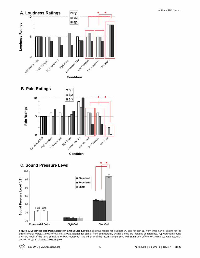
Figure 5. Loudness and Pain Sensation and Sound Levels. Subjective ratings for loudness (A) and for pain (B) from three naı̈ve subjects for thethree stimulus types. Stimulator was set at 90%. Ratings for stimuli from commercially available coils are included as reference. (C) Maximum soundpressure levels of the same stimuli. Error bars represent standard error of the mean. Comparisons with significant difference are marked with asterisks.doi:10.1371/journal.pone.0001923.g005
A Sham TMS System
PLoS ONE | www.plosone.org 6 April 2008 | Volume 3 | Issue 4 | e1923
found in either pain or loudness ratings in any subject for any of
the pairwise comparisons between Standard, Reversed and Sham.
(all p’s .0.1). For the Circ coil, no significant differences were
found in either pain or loudness ratings for any subject between
Standard and Reversed (all p’s .0.1) but there were (as expected)
significant differences when ratings for Sham were compared to
either Standard or Reversed; Sham was perceived as significantly
louder (all p’s,0.05) but also significantly less painful compared to
Standard or Reversed (all p’s,0.05). Discrimination of the Sham
and Standard stimuli using the Circ coil in the Perceptual
Discriminability Experiment was most likely due to these
differences in tactile and auditory sensation. Pain and loudness
ratings of commercially available Fig8 and Circ coils are shown in
the figure as reference.
Sound Pressure Level (SPL) Measurements. Measurements
of actual sound levels were not significantly different between
Standard, Reversed and Sham TMS with the Fig8 coil (all p’s .0.1).
With the Circ coil, Sham TMS was significantly louder compared to
the Standard and Reversed TMS (all p’s,0.05). Sound levels of
commercially available Fig8 and Circ coils are shown in the figure as
reference.
Discussion
In this study, we designed and validated a TMS stimulator
attachment that allows for the administration of both Standard
TMS stimulation and two types of control stimuli: Sham and
Reversed. The spatial and temporal characteristics of the
stimulation types were assessed by mathematical modeling and
search coil measurements. The levels of brain activation elicited by
the stimuli were assessed by measuring thresholds of activation in
the motor cortex. The extent to which these stimuli could be
interleaved in a double-blind manner was assessed directly in
discrimination tasks, and indirectly via pain and loudness ratings
and measurements of SPLs.
The electromagnetic and physiological effects of the equipment
were found to be appropriate. Standard stimuli through the custom
coils had profiles similar to the fields from ordinary commercial coils.
Stimuli were consistent and unaffected by preceding stimuli of other
types. Sham stimuli to motor cortex did not evoke MEPs even at
100% stimulator output. Reversed stimuli required significantly
more power than Standard stimuli did in activating MEPs.
The perceptual experiments under realistic experimental
conditions showed that naı̈ve subjects and non-naı̈ve investigators
using the Fig8 coil in our experimental settings could not
discriminate between the stimulus types. While individuals could
easily discriminate between Sham and Standard stimuli delivered
through the Circ coil (presumably due to Sham stimuli creating a
loud sound and less tactile sensation), discriminability between
Reversed and Standard stimuli was poor.
Stimuli with reversed polarity offer an alternative method of
delivering control stimuli when an optimal direction of stimulation
is known for the brain region of interest. Current-orientation-
specific effects have not only been shown in the primary motor
area [20,29] but have also been reported in prefrontal and visual
cortices [24,25]. Because a change in stimulus polarity can change
the threshold of activation in these regions, the effects of
stimulation can be controlled without changing coil location or
stimulus intensity. This is particularly meaningful for the use of the
Circ coil, where Sham stimuli are discriminable. One should be
careful when using reverse stimuli as a control condition, as
reversal of the coil (which reduces the stimulation intensity by
approximately 10–20 %) may not be sufficient in some cases and
may also start recruiting undesired neuronal populations.
Another potential application of the equipment is its ability to
stimulate opposite hemispheres of the brain without coil
repositioning, with as little as 3 ms intervals. In the past,
experimenters have found that flipping the coil over the same
stimulation site can control the side on which lateralized motor
and visual effects occur. The current switch offers such control
with more stable coil positioning, and the ability to study inter-
hemispheric interactions on a fairly short timescale.
In summary, we have developed and validated a TMS
attachment that allows one to intermix real and sham TMS on
a single-trial basis in a controlled double-blind manner. Experi-
mental and control conditions can be alternated on a millisecond
time-scale. Switching between conditions does not require coil
movement or reconfiguration, and can be completely automated.
The conditions can be double-blinded to counteract both placebo
effects and experimenter bias. The attachment validated here is
compatible with a commercially available TMS device in common
use in the research community, and the simple design principle
should be applicable to other TMS devices. Future research testing
its perception when applied to other scalp sites, measurements of
interindividual variability in larger number of subjects and
application in ‘real’ research studies are warranted.
Materials and Methods
SubjectsA total of eight naı̈ve and healthy subjects participated in the study
(mean age 27.3, range 23–39, 2 females, 7 right handed). Two non-
naı̈ve healthy investigators who have been performing TMS
experiments for at least the past 6 years (age 28, 36; 1 female; both
right-handed) also participated in the study. None had contraindi-
cations to TMS [30], had known neurological or psychiatric
disorders or were on medication. All subjects gave written consent
and wore earplugs throughout the study. The study was approved by
the Investigational Review Boards from California Institute of
Technology and Stanford University School of Medicine.
TMS DeviceTMS was performed with two commercially available Magstim
200 stimulators and a Bistim module (Magstim Company,
Carmarthenshire, UK). The inter-trial timing of the TMS pulses
and the direction of current were controlled using Matlab
(Mathworks, MA, USA) using Activewire (ActiveWire Inc.,
Campbell, CA, USA). Inter-stimulus-intervals (ISI) between two
TMS pulses were controlled using the Bistim module when
millisecond precision was necessary. Either commercially available
Fig8 and Circ coils or the custom-made Fig8 and Circ coils were
used. In case of the custom-made coils, the coils were connected
through the custom switch-box attachment that allows switching
between Standard, Reversed and Sham TMS. All data analyses
were performed using Matlab. The custom setup was made to our
specifications by Magstim in which we paid for labor and parts.
Magstim had no intellectual input to the experimental design,
interpretation of the results or in writing the manuscript.
Mathematical Modeling of Electric FieldsThe magnetic field B
!at a point r can be related to the current
in the stimulating coil, I, by the law of Biot and Savart [31]
~BB(r)~m0IN
4p
ðd~ll0|(~rr�~rr0)~rr�~rr0j j3
, ð1Þ
where N is the number of turns in the coil, m0 is the permeability of
A Sham TMS System
PLoS ONE | www.plosone.org 7 April 2008 | Volume 3 | Issue 4 | e1923
free space (4 p610-7 T?m/A), and the integral of d~ll0 is over the
coil path and~rr0 is a vector indicating the position of the coil path.
The induced electric field can be calculated using the vector
potential, ~AA(~rr), which is related to the current in the coil by the
expression [31]
~AA(~rr)~m0IN
4p
d~ll0
~rr�~rr0j j : ð2Þ
The vector potential is in turn related to the electric and magnetic
fields by the expression [31]
~BB~+|~AA ~EE~{L~AALt: ð3Þ
We calculated the integrals of Eq. (1) and (2) analytically along a
line segment and then approximate our coil as a 32-sided polygon
and summed the contribution from each side. Other assumptions
made were following [32] and specifications of Magstim 200:
capacitance (C) = 20061026 F, resistance (R) = 3 V, voltage of
power source (V0) = 200 V, radius of wire = 1 mm, number of
turns of coil (N) = 14, mean radius of coil = 4.5 cm for Circ and
3.5 cm for Fig8 coil, magnetic permeability (mu0) = 4 * pi * 1e-7,
and measurement plane distance = 10 mm.
Search Coil MeasurementsStandard, Reversed and Sham TMS with the custom-made
Fig8 and Circ coils and Standard TMS with commercially
available Fig8 and Circ coils were applied to a search coil (one
10 mm diameter turn of copper wire) that was connected to an
electric circuit. The search coil was placed at the center of the Fig8
coil where the two sets of coils intersect and on the turns of the
Circ coil. This electric circuit was the same as that used in
Corthout et al. [33]. The electric circuit consisted of a resistor
R1 = 100 kV (representing longitudinal axonal resistance) in series
with a parallel resistor Rm = 1 kV and capacitor Cm = 0.15 mF
(representing membrane resistance and capacitance, respectively).
Note that these values are not critical but were chosen to
approximate the high longitudinal axonal resistance and a realistic
membrane time constant [34]. The search coil EMF was recorded
with an oscilloscope (Tektronix TDS 5104, Tektronix, OR USA).
Electro-motive force (EMF) was measured for single-pulse TMS
and dual-pulse TMS with 10 ms ISI, single-pulse TMS while
varying the distance of the search coil from the TMS coil surface,
and single-pulse TMS while varying stimulus intensity. When
dual-pulse TMS was applied, the order in which the two Magstim
200 stimulators were used to deliver TMS was pseudo-randomized
and counter-balanced to avoid the effect of stimulator. There were
20 trials per condition. Statistical comparisons were performed
using t-tests or one-way analysis of variance (ANOVA) on rise-
time, maximum amplitude and area-under-the-curve of EMF. We
report EMF amplitude as rise-time measures, area-under-the-
curve measures showed similar results.
Motor PhysiologyMotor threshold was obtained for Standard, Reversed and
Sham TMS using the Fig8 and Circ coils on three naı̈ve subjects.
First, subjects were seated comfortably and the coil was positioned
using a coil-holder (Brainsight, Rogue Research Inc, Quebec
Canada), at the scalp position at which Standard TMS induced
motor-evoked potentials (MEPs) of maximal peak-to-peak ampli-
tude in the target right first dorsal interosseus (FDI) muscle. Two
electrodes were placed on the belly and tendon of the target
muscle and a ground electrode of 30 mm diameter was placed on
the right forearm after appropriate skin preparation. MEPs were
collected using CED 1902 amplifiers (Cambridge Electronic
Design (CED), Cambridge UK) with a band pass of 0.3–
3,000 Hz. Following pre-amplification, the signal was digitized
at a sampling rate of 6 kHz using a CED 1404 interface (CED,
Cambridge, UK). Data was collected and analyzed using Signal
software (CED, Cambridge, UK) and Matlab.
After the optimal location was determined and the coil
positioned, motor threshold for Standard, Reversed and Sham
TMS were determined for each subject in a pseudo-randomized
and counterbalanced order. Motor threshold was defined as the
minimal intensity of stimulation capable of inducing MEPs of
more than 50 uV in at least six out of ten trials, during which the
subjects maintained complete muscle relaxation, as documented
by the electromyogram recording from at least 200 ms prior to
TMS. There was an interval of 6–10 sec between trials. These
were tested for both the Fig8 and Circ coils also in pseudo-
randomized and counterbalanced order.
Perceptual DiscriminabilityFive naı̈ve subjects who were not part of the aforementioned
motor physiology experiment performed a Stroop task while they
performed perceptual discrimination tasks. We chose this study
design because in most TMS studies, subjects perform a cognitive
task while they receive TMS, and we wanted to test whether
subjects can discriminate whether they received Standard or sham
TMS applied to the top of the head (Cz according to the
International 10–20 Electroencephalogram (EEG) system) under
these conditions. Preliminary studies with TMS applied to the F3/
F4 (prefrontal location) showed similar results. A list of color
names was printed on the computer screen that was confirmed to
be easily readable by subjects. The color of the printed words was
incongruent to the names of the words. Subjects’ were instructed
to verbally name the color of the words as fast and as accurately as
possible, and an investigator (AH) recorded all responses manually.
Response times were not recorded as the detailed performance of
the Stroop task was not the main focus of this study. Two non-
naı̈ve investigators also performed perceptual discrimination tasks
while they held the coil in their hands. We chose to investigate
non-naı̈ve investigators applying TMS to test whether Standard/
Reversed vs. Sham TMS can be blinded from investigators as well.
First, naı̈ve subjects received 12 pulses of Standard, Reversed
and Sham TMS at 90% maximum output and were asked at the
end whether there were different kinds of TMS pulses using the
Fig8 coil. We also asked them specifically whether they felt
different intensities or sensations. Since questioning cued the
subjects to the fact that there were three different types of TMS,
we did not repeat this task using the Circ coil.
Next, we performed a two-alternative forced-choice task (2
AFC) using the Fig8 and Circ coils. Whenever TMS was applied
to the subjects, in addition to continuing to perform the Stroop
task, subjects were also instructed to press key 1 if they thought
that they received real TMS (Standard or Reversed TMS) and 2 if
they thought they received Sham TMS. There were a total of 40
pulses per task with 20 pulses or Standard or Reversed TMS and
20 pulses of Sham TMS. TMS was applied at a stimulus intensity
of 50, 70 and 90% of maximal output for the Fig8 coil and 50%
for the Circ coil. We did not test higher intensities for the Circ coil,
as the subjects could easily identify whether they received a
Standard/Reversed or Sham TMS.
Since the subjects could discriminate between Standard/
Reversed TMS and Sham TMS for the Circ coil, we further
A Sham TMS System
PLoS ONE | www.plosone.org 8 April 2008 | Volume 3 | Issue 4 | e1923
tested to see if subjects could discriminate between Standard and
Reversed TMS. There were 40 pulses of Standard and Reversed
TMS (20 pulses each) at 90% stimulus intensity.
Hence, a total of 212 pulses were applied for the six tasks for
each naı̈ve subject: one debriefing task consisting of 12 trials, four
tasks discriminating between Standard/Reversed and Sham TMS
consisting of 40 trials per task, and one task discriminating
between Standard and Reversed TMS consisting of 40 trials.
Two non-naı̈ve investigators performed the 4 perceptual
discrimination tasks while holding the TMS coil in their hands,
without performing the Stroop task. Hence, there were 200 trials
total per investigator.
To measure discriminability, d-prime (d’) [35] was calculated
for each subject using correct hits (correctly identifying Standard
or Reversed TMS) and false alarms (incorrectly identifying Sham
TMS as being Standard or Reversed TMS).
Pain and Loudness RatingsThree subjects who were part of the motor physiology
experiment rated their perceptions of pain and acoustic intensity
during TMS with Fig8 and Circ coils using a visual analogue scale
(VAS; scale from 0 to 10, 0 being no pain/acoustic intensity, 5
being moderate pain/acoustic intensity and 10 being worst
imaginable pain/loudest known acoustic intensity). These two
measurements were obtained in separate experiments. TMS was
applied at 90% maximal output to the left prefrontal region (F3 of
the International 10–20 EEG system). This site was chosen
because the prefrontal region is a common location to apply TMS
in clinical trials of depression, as well as in cognitive neuroscience
studies. Ten trials per condition (Standard, Reversed, Sham) were
randomly intermixed, using either the Fig8 or Circ coil. Mean and
standard error of the mean were calculated for each subject for
each condition. Conditions were compared using paired t-tests
between Standard and Reversed and between Standard and Sham
TMS (p = 0.05).
Sound Pressure Level MeasurementsMaximum sound pressure levels of commercially available Fig8
and Circ coils as well as Standard, Reversed and Sham TMS using
custom-made Fig8 and Circ coils at 90% maximum output were
measured using a sound pressure monitor (A-weighted, 150 cm
from coil surface; 10 trials per condition). Conditions were
compared using paired t-tests between Standard and Reversed
and between Real and Sham TMS (p = 0.05).
Supporting Information
Text S1 Supporting Text
Found at: doi:10.1371/journal.pone.0001923.s001 (0.05 MB
DOC)
Acknowledgments
We thank Professors John D.E. Gabrieli (MIT) and Allan L. Reiss
(Stanford) for support throughout the study.
Author Contributions
Conceived and designed the experiments: SS FH. Performed the
experiments: DW FH AH. Analyzed the data: FH AH GG. Wrote the
paper: SS DW FH GG.
References
1. Hallett M (2000) Transcranial magnetic stimulation and the human brain.
Nature 406: 147–150.
2. Barker AT, Jalinous R, Freeston IL (1985) Non-invasive magnetic stimulation of
human motor cortex. Lancet 1: 1106–1107.
3. Hallett M, Chokroverty S (2005) Magnetic Stimulation in Clinical Neurophys-
iology. Burlington, MA, USA: Butterworth-Heinemann.
4. Chen R (2000) Studies of human motor physiology with transcranial magnetic
stimulation. Muscle Nerve Suppl 9: S26–32.
5. Maeda F, Pascual-Leone A (2003) Transcranial magnetic stimulation: studying
motor neurophysiology of psychiatric disorders. Psychopharmacology (Berl) 168:
359–376.
6. George MS, Belmaker RH (2006) Transcranial Magnetic Stimulation in Clinical
Psychiatry. Arlington, VA: American Psychiatric Publishing.
7. Walsh V, Pascual-Leone A, Kosslyn SM (2005) Transcranial Magnetic
Stimulation: A Neurochronometrics of Mind. Cambridge, MA, USA: M.I.T.
Press.
8. Pascual-Leone A, Walsh V, Rothwell J (2000) Transcranial magnetic stimulation
in cognitive neuroscience–virtual lesion, chronometry, and functional connec-
tivity. Curr Opin Neurobiol 10: 232–237.
9. Paus T (2005) Inferring causality in brain images: a perturbation approach.
Philos Trans R Soc Lond B Biol Sci 360: 1109–1114.
10. Lisanby SH (2004) Brain Stimulation in Psychiatric Treatment. Arlington, VA,
USA: American Psychiatric Publishing.
11. Kobayashi M, Pascual-Leone A (2003) Transcranial magnetic stimulation in
neurology. Lancet Neurol 2: 145–156.
12. Okabe S, Ugawa Y, Kanazawa I (2003) 0.2-Hz repetitive transcranial magnetic
stimulation has no add-on effects as compared to a realistic sham stimulation in
Parkinson’s disease. Mov Disord 18: 382–388.
13. Vucic S, Kiernan MC (2006) Novel threshold tracking techniques suggest that
cortical hyperexcitability is an early feature of motor neuron disease. Brain 129:
2436–2446.
14. Jang SH, Cho SH, Kim YH, You SH, Kim SH, et al. (2005) Motor recovery
mechanism of diffuse axonal injury: a combined study of transcranial magnetic
stimulation and functional MRI. Restor Neurol Neurosci 23: 51–56.
15. Mulleners WM, Chronicle EP, Vredeveld JW, Koehler PJ (2002) Visual cortex
excitability in migraine before and after valproate prophylaxis: a pilot study
using TMS. Eur J Neurol 9: 35–40.
16. Robertson EM, Theoret H, Pascual-Leone A (2003) Studies in cognition: the
problems solved and created by transcranial magnetic stimulation. J Cogn
Neurosci 15: 948–960.
17. Harrington A (2002) ‘‘Seeing’’ the placebo effect: historical legacies and present
opportunities. In: Guess HA, Kleinman A, Kusek JW, Engel LW, eds (2002) The
Science of the Placebo. London: BMJ Books.
18. Schatzberg AF, Kraemer HC (2000) Use of placebo control groups in evaluating
efficacy of treatment of unipolar major depression. Biol Psychiatry 47: 736–744.
19. Kaptchuk TJ (2000) Debate over the history of placebos in medicine. Altern
Ther Health Med 6: 18, 20.
20. Brasil-Neto JP, Cohen LG, Panizza M, Nilsson J, Roth BJ, et al. (1992) Optimal
focal transcranial magnetic activation of the human motor cortex: effects of coil
orientation, shape of the induced current pulse, and stimulus intensity. J Clin
Neurophysiol 9: 132–136.
21. Kammer T, Beck S, Thielscher A, Laubis-Herrmann U, Topka H (2001) Motor
thresholds in humans: a transcranial magnetic stimulation study comparing
different pulse waveforms, current directions and stimulator types. Clin
Neurophysiol 112: 250–258.
22. Pascual-Leone A, Cohen LG, Brasil-Neto JP, Hallett M (1994) Non-invasive
differentiation of motor cortical representation of hand muscles by mapping of
optimal current directions. Electroencephalogr Clin Neurophysiol 93: 42–48.
23. Sakai K, Ugawa Y, Terao Y, Hanajima R, Furubayashi T, et al. (1997)
Preferential activation of different I waves by transcranial magnetic stimulation
with a figure-of-eight-shaped coil. Exp Brain Res 113: 24–32.
24. Kammer T, Beck S, Erb M, Grodd W (2001) The influence of current direction
on phosphene thresholds evoked by transcranial magnetic stimulation. Clin
Neurophysiol 112: 2015–2021.
25. Hill AC, Davey NJ, Kennard C (2000) Current orientation induced by magnetic
stimulation influences a cognitive task. Neuroreport 11: 3257–3259.
26. Ruohonen J, Ollikainen M, Nikouline V, Virtanen J, Ilmoniemi RJ (2000) Coil
design for real and sham transcranial magnetic stimulation. IEEE Trans Biomed
Eng 47: 145–148.
27. Amassian VE, Eberle L, Maccabee PJ, Cracco RQ (1992) Modelling magnetic
coil excitation of human cerebral cortex with a peripheral nerve immersed in a
brain-shaped volume conductor: the significance of fiber bending in excitation.
Electroencephalogr Clin Neurophysiol 85: 291–301.
28. Illmoniemi RJ, Ruohonen J, Karhu J (1999) Transcranial magnetic stimulation-a
new tool for functional imaging of the brain. Crit Rev Biomed Eng 27: 241–284.
29. Mills KR, Boniface SJ, Schubert M (1992) Magnetic brain stimulation with a
double coil: the importance of coil orientation. Electroencephalogr Clin
Neurophysiol 85: 17–21.
30. Wassermann EM (1998) Risk and safety of repetitive transcranial magnetic
stimulation: report and suggested guidelines from the International Workshop
A Sham TMS System
PLoS ONE | www.plosone.org 9 April 2008 | Volume 3 | Issue 4 | e1923

on the Safety of Repetitive Transcranial Magnetic Stimulation, June 5–7, 1996.
Electroencephalogr Clin Neurophysiol 108: 1–16.31. Jackson JD (1998) Classical electrodynamics. New York: Wiley.
32. Roth BJ, Basser PJ (1990) A model of the stimulation of a nerve fiber by
electromagnetic induction. IEEE Trans Biomed Eng 37: 588–597.33. Corthout E, Barker AT, Cowey A (2001) Transcranial magnetic stimulation.
Which part of the current waveform causes the stimulation? Exp Brain Res 141:128–132.
34. Barker AT, Garnham CW, Freeston IL (1991) Magnetic nerve stimulation: the
effect of waveform on efficiency, determination of neural membrane time
constants and the measurement of stimulator output. Electroencephalogr Clin
Neurophysiol Suppl 43: 227–237.
35. Green D, Swets J (1966) Signal Detection Theory and Psychophysics.
Melbourne, Florida: Robert E. Kreiger Publishing Co., Inc.
A Sham TMS System
PLoS ONE | www.plosone.org 10 April 2008 | Volume 3 | Issue 4 | e1923
Related Documents