FBC-0060 February 2014, Rev. 1 © 2014 Fluke Corporation. All rights reserved. Specifications are subject to change without notice. All product names are trademarks of their respective companies. ESA609 Electrical Safety Analyzer Users Manual

Welcome message from author
This document is posted to help you gain knowledge. Please leave a comment to let me know what you think about it! Share it to your friends and learn new things together.
Transcript
FBC-0060 February 2014, Rev. 1 © 2014 Fluke Corporation. All rights reserved. Specifications are subject to change without notice. All product names are trademarks of their respective companies.
ESA609 Electrical Safety Analyzer
Users Manual
Warranty and Product Support
Fluke Biomedical warrants this instrument against defects in materials and workmanship for one year from the date of original purchase OR two years if at the end of your first year you send the instrument to a Fluke Biomedical service center for calibration. You will be charged our customary fee for such calibration. During the warranty period, we will repair or at our option replace, at no charge, a product that proves to be defective, provided you return the product, shipping prepaid, to Fluke Biomedical. This warranty covers the original purchaser only and is not transferable. The warranty does not apply if the product has been damaged by accident or misuse or has been serviced or modified by anyone other than an authorized Fluke Biomedical service facility. NO OTHER WARRANTIES, SUCH AS FITNESS FOR A PARTICULAR PURPOSE, ARE EXPRESSED OR IMPLIED. FLUKE SHALL NOT BE LIABLE FOR ANY SPECIAL, INDIRECT, INCIDENTAL OR CONSEQUENTIAL DAMAGES OR LOSSES, INCLUDING LOSS OF DATA, ARISING FROM ANY CAUSE OR THEORY.
This warranty covers only serialized products and their accessory items that bear a distinct serial number tag. Recalibration of instruments is not covered under the warranty.
This warranty gives you specific legal rights and you may also have other rights that vary in different jurisdictions. Since some jurisdictions do not allow the exclusion or limitation of an implied warranty or of incidental or consequential damages, this limitation of liability may not apply to you. If any provision of this warranty is held invalid or unenforceable by a court or other decision-maker of competent jurisdiction, such holding will not affect the validity or enforceability of any other provision.
7/07
Notices
All Rights Reserved Copyright 2014, Fluke Biomedical. No part of this publication may be reproduced, transmitted, transcribed, stored in a retrieval system, or translated into any language without the written permission of Fluke Biomedical.
Copyright Release Fluke Biomedical agrees to a limited copyright release that allows you to reproduce manuals and other printed materials for use in service training programs and other technical publications. If you would like other reproductions or distributions, submit a written request to Fluke Biomedical.
Unpacking and Inspection Follow standard receiving practices upon receipt of the instrument. Check the shipping carton for damage. If damage is found, stop unpacking the instrument. Notify the carrier and ask for an agent to be present while the instrument is unpacked. There are no special unpacking instructions, but be careful not to damage the instrument when unpacking it. Inspect the instrument for physical damage such as bent or broken parts, dents, or scratches.
Technical Support For application support or answers to technical questions, either email [email protected] or call 1-800- 850-4608 or 1-440-248-9300. In Europe, email [email protected] or call +31-40-2965314.
Claims Our routine method of shipment is via common carrier, FOB origin. Upon delivery, if physical damage is found, retain all packing materials in their original condition and contact the carrier immediately to file a claim. If the instrument is delivered in good physical condition but does not operate within specifications, or if there are any other problems not caused by shipping damage, please contact Fluke Biomedical or your local sales representative.
Returns and Repairs Return Procedure
All items being returned (including all warranty-claim shipments) must be sent freight-prepaid to our factory location. When you return an instrument to Fluke Biomedical, we recommend using United Parcel Service, Federal Express, or Air Parcel Post. We also recommend that you insure your shipment for its actual replacement cost. Fluke Biomedical will not be responsible for lost shipments or instruments that are received in damaged condition due to improper packaging or handling. Use the original carton and packaging material for shipment. If they are not available, we recommend the following guide for repackaging:
Use a double–walled carton of sufficient strength for the weight being shipped. Use heavy paper or cardboard to protect all instrument surfaces. Use nonabrasive material around all projecting parts. Use at least four inches of tightly packed, industry-approved, shock-absorbent material around the instrument.
Returns for partial refund/credit: Every product returned for refund/credit must be accompanied by a Return Material Authorization (RMA) number, obtained from our Order Entry Group at 1-440-498-2560.
Repair and calibration: To find the nearest service center, go to www.flukebiomedical.com/service or In the U.S.A.:
Cleveland Calibration Lab Tel: 1-800-850-4608 x2564 Email: [email protected]
In Europe, Middle East, and Africa: Eindhoven Calibration Lab Tel: +31-40-2675300 Email: [email protected]
Everett Calibration Lab Tel: 1-888-99 FLUKE (1-888-993-5853) Email: [email protected]
In Asia: Everett Calibration Lab Tel: +425-446-6945 Email: [email protected]
To ensure the accuracy of the Product is maintained at a high level, Fluke Biomedical recommends the product be calibrated at least once every 12 months. Calibration must be done by qualified personnel. Contact your local Fluke Biomedical representative for calibration.
Certification This instrument was thoroughly tested and inspected. It was found to meet Fluke Biomedical’s manufacturing specifications when it was shipped from the factory. Calibration measurements are traceable to the National Institute of Standards and Technology (NIST). Devices for which there are no NIST calibration standards are measured against in-house performance standards using accepted test procedures.
WARNING Unauthorized user modifications or application beyond the published specifications may result in electrical shock hazards or improper operation. Fluke Biomedical will not be responsible for any injuries sustained due to unauthorized equipment modifications.
Restrictions and Liabilities Information in this document is subject to change and does not represent a commitment by Fluke Biomedical. Changes made to the information in this document will be incorporated in new editions of the publication. No responsibility is assumed by Fluke Biomedical for the use or reliability of software or equipment that is not supplied by Fluke Biomedical, or by its affiliated dealers.
Manufacturing Location The ESA609 Electrical Safety Analyzer is manufactured at Fluke Biomedical, 6920 Seaway Blvd., Everett, WA, U.S.A.

i
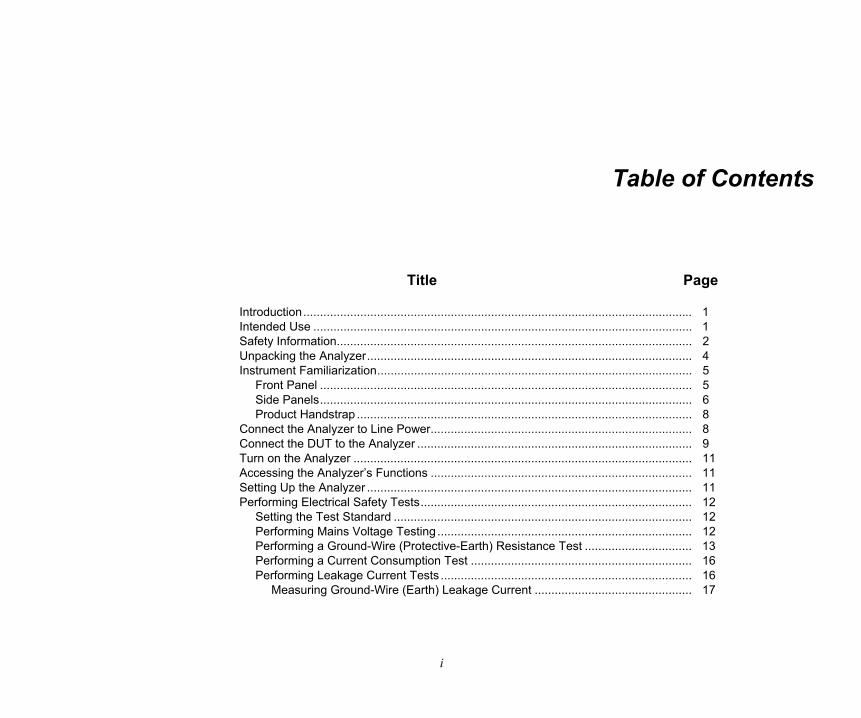
Table of Contents
Title Page
Introduction .................................................................................................................... 1 Intended Use ................................................................................................................. 1 Safety Information .......................................................................................................... 2 Unpacking the Analyzer ................................................................................................. 4 Instrument Familiarization .............................................................................................. 5
Front Panel ............................................................................................................... 5 Side Panels ............................................................................................................... 6 Product Handstrap .................................................................................................... 8
Connect the Analyzer to Line Power .............................................................................. 8 Connect the DUT to the Analyzer .................................................................................. 9 Turn on the Analyzer ..................................................................................................... 11 Accessing the Analyzer’s Functions .............................................................................. 11 Setting Up the Analyzer ................................................................................................. 11 Performing Electrical Safety Tests ................................................................................. 12
Setting the Test Standard ......................................................................................... 12 Performing Mains Voltage Testing ............................................................................ 12 Performing a Ground-Wire (Protective-Earth) Resistance Test ................................ 13 Performing a Current Consumption Test .................................................................. 16 Performing Leakage Current Tests ........................................................................... 16
Measuring Ground-Wire (Earth) Leakage Current ............................................... 17
ESA609 Users Manual
ii
Performing a Chassis (Enclosure) Leakage Test ................................................. 19 Performing a Direct-Equipment Leakage Test ..................................................... 21
Making Point-To-Point Measurements ........................................................................... 23 Measuring Resistance ............................................................................................... 23 Measuring Leakage Current ...................................................................................... 23
Maintenance .................................................................................................................. 24 Testing and Replacing the Fuses .............................................................................. 24 Cleaning the Analyzer ............................................................................................... 25
Replaceable Parts ......................................................................................................... 26 Accessories ................................................................................................................... 28 Specifications ................................................................................................................. 29 Detailed Specifications................................................................................................... 30

iii
List of Tables
Table Title Page
1. Symbols ................................................................................................................................ 2 2. Front Panel Controls and Connections ................................................................................. 5 3. Side Panel Connections ........................................................................................................ 7 4. Schematic Abbreviations ...................................................................................................... 14 5. Test Names Based on Selected Standard ............................................................................ 16 6. Replaceable Parts ................................................................................................................ 26 7. Accessories .......................................................................................................................... 28

ESA609 Users Manual
iv
v
List of Figures
Figure Title Page
1. Front-Panel Controls and Connections ................................................................................. 5 2. Side-Panel Connections ....................................................................................................... 6 3. Product Handstrap ................................................................................................................ 8 4. DUT Connections to the Analyzer ......................................................................................... 10 5. Start screen .......................................................................................................................... 11 6. Mains Voltage Test ............................................................................................................... 12 7. Ground-Wire Resistence Test ............................................................................................... 13 8. Ground-Wire (Protective-Earth) Resistance Measurement Schematic ................................. 15 9. Leakage Current Test ........................................................................................................... 16 10. Earth-Leakage Current Test Schematic ................................................................................ 18 11. Enclosure-Leakage Current Test Schematic ........................................................................ 20 12. Direct-Equipment Leakage Test Schematic .......................................................................... 22 13. Point-to-Point Resistance Test ............................................................................................. 23 14. Fuse Access ......................................................................................................................... 25

ESA609 Users Manual
vi
1
Electrical Safety Analyzer
Introduction The Fluke Biomedical ESA609 Electrical Safety Analyzer (the Analyzer) is a full-featured, compact, portable analyzer that verifies the electrical safety of medical devices. The Analyzer tests to domestic (ANSI/AAMI ES1, NFPA 99) and international (and parts of IEC 62353 and IEC 60601-1) electrical-safety standards. The integrated ANSI/AAMI ES1 and IEC 60601-1 patient loads are easy to select.
The Analyzer does the following tests:
• Line (Mains) voltage
• Ground Wire (or Protective Earth) Resistance
• Equipment current
• Ground Wire (Earth) leakage
• Chassis (Enclosure) leakage
• Direct equipment leakage
• Point to point leakage and resistance
Intended Use The Product is an electronic signal source and measurement device for verifying the electrical safety of medical devices.
The intended user is a trained biomedical equipment technician who performs periodic preventative maintenance checks on medical equipment in service. Users can be associated with hospitals, clinics, original equipment manufacturers and independent service companies that repair and service medical equipment. The end user is an individual, trained in medical instrumentation technology.
This Product is intended to be used in the laboratory environment, outside of the patient care area, and is not intended for use on patients, or to test devices while connected to patients. This Product is not intended to be used to calibrate medical equipment. It is intended for over-the-counter use.
ESA609 Users Manual
2
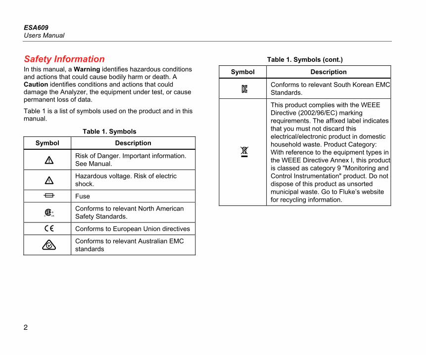
Safety Information In this manual, a Warning identifies hazardous conditions and actions that could cause bodily harm or death. A Caution identifies conditions and actions that could damage the Analyzer, the equipment under test, or cause permanent loss of data.
Table 1 is a list of symbols used on the product and in this manual.
Table 1. Symbols
Symbol Description
Risk of Danger. Important information. See Manual.
Hazardous voltage. Risk of electric shock.
Fuse
Conforms to relevant North American Safety Standards.
Conforms to European Union directives
Conforms to relevant Australian EMC standards
Table 1. Symbols (cont.)
Symbol Description
Conforms to relevant South Korean EMC Standards.
This product complies with the WEEE Directive (2002/96/EC) marking requirements. The affixed label indicates that you must not discard this electrical/electronic product in domestic household waste. Product Category: With reference to the equipment types in the WEEE Directive Annex I, this product is classed as category 9 "Monitoring and Control Instrumentation" product. Do not dispose of this product as unsorted municipal waste. Go to Fluke’s website for recycling information.
Electrical Safety Analyzer Safety Information
3
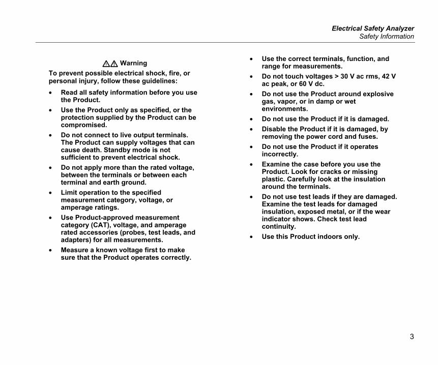
Warning To prevent possible electrical shock, fire, or personal injury, follow these guidelines: • Read all safety information before you use
the Product. • Use the Product only as specified, or the
protection supplied by the Product can be compromised.
• Do not connect to live output terminals. The Product can supply voltages that can cause death. Standby mode is not sufficient to prevent electrical shock.
• Do not apply more than the rated voltage, between the terminals or between each terminal and earth ground.
• Limit operation to the specified measurement category, voltage, or amperage ratings.
• Use Product-approved measurement category (CAT), voltage, and amperage rated accessories (probes, test leads, and adapters) for all measurements.
• Measure a known voltage first to make sure that the Product operates correctly.
• Use the correct terminals, function, and range for measurements.
• Do not touch voltages > 30 V ac rms, 42 V ac peak, or 60 V dc.
• Do not use the Product around explosive gas, vapor, or in damp or wet environments.
• Do not use the Product if it is damaged. • Disable the Product if it is damaged, by
removing the power cord and fuses. • Do not use the Product if it operates
incorrectly. • Examine the case before you use the
Product. Look for cracks or missing plastic. Carefully look at the insulation around the terminals.
• Do not use test leads if they are damaged. Examine the test leads for damaged insulation, exposed metal, or if the wear indicator shows. Check test lead continuity.
• Use this Product indoors only.
ESA609 Users Manual
4
• Use only the mains power cord and connector approved for the voltage and plug configuration in your country and rated for the Product.
• Make sure the ground conductor in the mains power cord is connected to a protective earth ground. Disruption of the protective earth could put voltage on the chassis that could cause death.
• Replace the mains power cord if the insulation is damaged or if the insulation shows signs of wear.
• Connect the common test lead before the live test lead and remove the live test lead before the common test lead.
• Keep fingers behind the finger guards on the probes.
• Do not use test leads if they are damaged. Examine the test leads for damaged insulation and measure a known voltage.
• Do not use a current measurement as an indication that a circuit is safe to touch. A voltage measurement is necessary to know if a circuit is hazardous.
Unpacking the Analyzer Carefully unpack all items from the box and check that you have the following items:
• ESA609
• Safety Sheet
• Users Manual CD
• Carrying case
• Power cord
• ESA USA Accessory Kit (USA, Australia, and Israel only)
• ESA EUR Accessory Kit
• Null Post Adapter
Electrical Safety Analyzer Instrument Familiarization
5
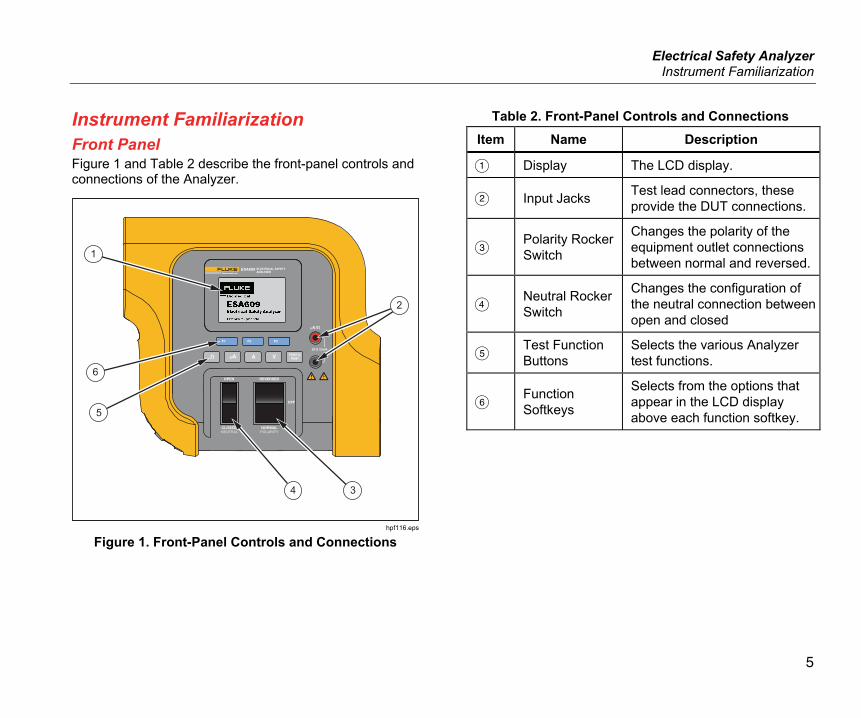
Instrument Familiarization Front Panel Figure 1 and Table 2 describe the front-panel controls and connections of the Analyzer.
2
5
6
1
4 3
hpf116.eps
Figure 1. Front-Panel Controls and Connections
Table 2. Front-Panel Controls and Connections Item Name Description
Display The LCD display.
Input Jacks Test lead connectors, these provide the DUT connections.
Polarity Rocker Switch
Changes the polarity of the equipment outlet connections between normal and reversed.
Neutral Rocker Switch
Changes the configuration of the neutral connection between open and closed
Test Function Buttons
Selects the various Analyzer test functions.
Function Softkeys
Selects from the options that appear in the LCD display above each function softkey.
ESA609 Users Manual
6
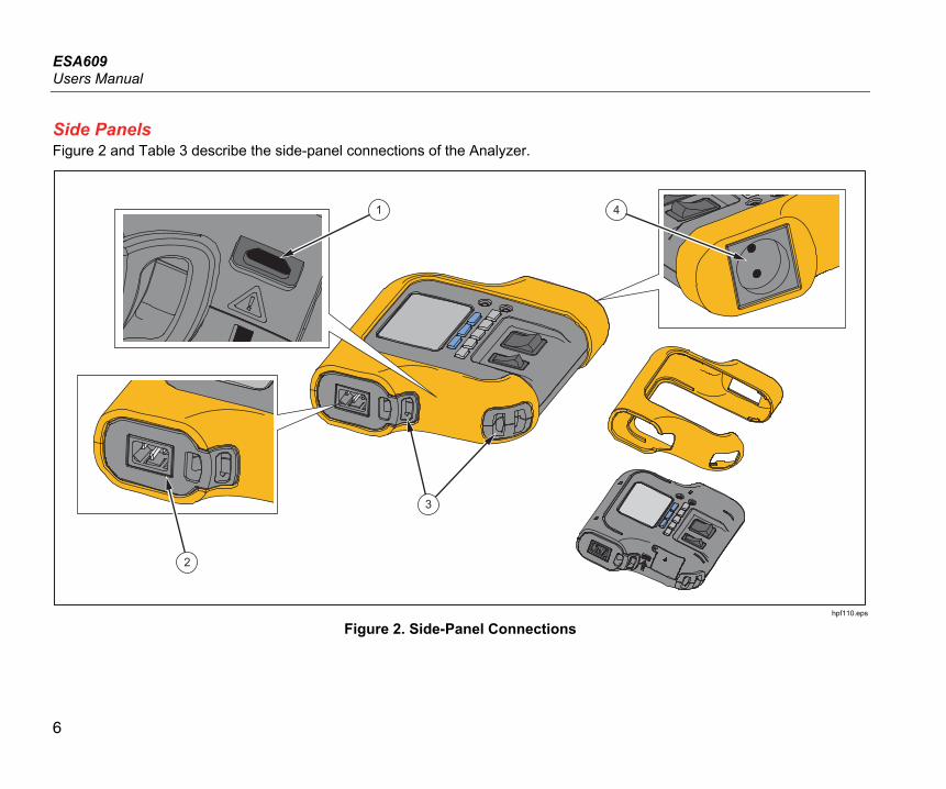
Side Panels Figure 2 and Table 3 describe the side-panel connections of the Analyzer.
2
3
1 4
hpf110.eps
Figure 2. Side-Panel Connections
Electrical Safety Analyzer Instrument Familiarization
7
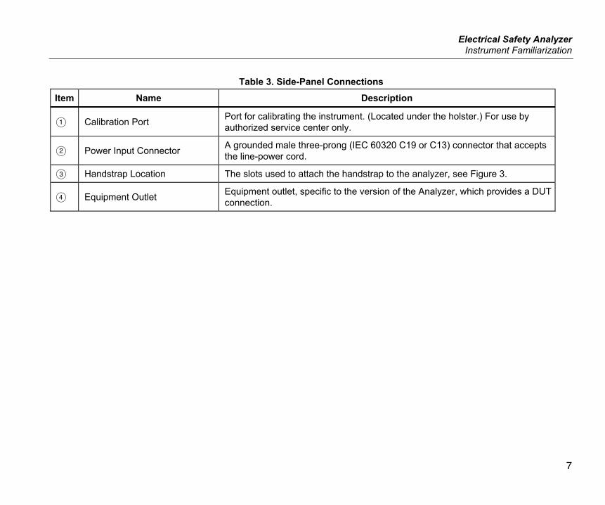
Table 3. Side-Panel Connections Item Name Description
Calibration Port Port for calibrating the instrument. (Located under the holster.) For use by authorized service center only.
Power Input Connector A grounded male three-prong (IEC 60320 C19 or C13) connector that accepts the line-power cord.
Handstrap Location The slots used to attach the handstrap to the analyzer, see Figure 3.
Equipment Outlet Equipment outlet, specific to the version of the Analyzer, which provides a DUT connection.
ESA609 Users Manual
8
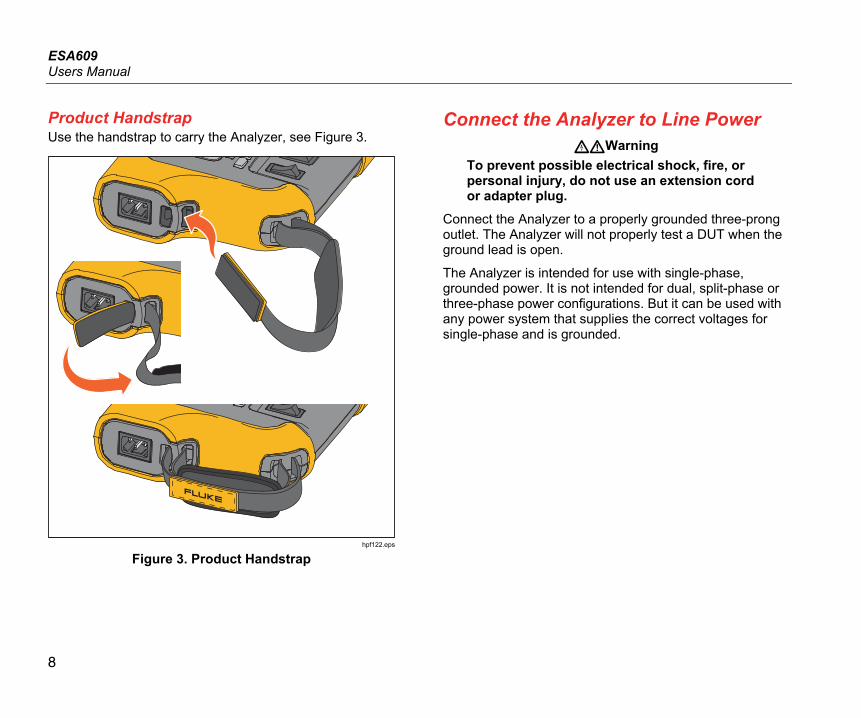
Product Handstrap Use the handstrap to carry the Analyzer, see Figure 3.
hpf122.eps
Figure 3. Product Handstrap
Connect the Analyzer to Line Power Warning
To prevent possible electrical shock, fire, or personal injury, do not use an extension cord or adapter plug.
Connect the Analyzer to a properly grounded three-prong outlet. The Analyzer will not properly test a DUT when the ground lead is open.
The Analyzer is intended for use with single-phase, grounded power. It is not intended for dual, split-phase or three-phase power configurations. But it can be used with any power system that supplies the correct voltages for single-phase and is grounded.
Electrical Safety Analyzer Connect the DUT to the Analyzer
9
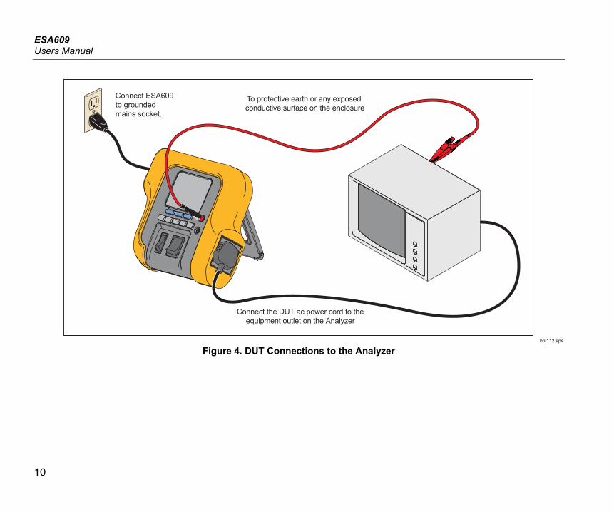
Connect the DUT to the Analyzer A Device Under Test (DUT) can be connected in a number of different ways depending on the device and the number of connections needed for a full electrical safety test. Figure 4 shows a DUT connected to the test receptacle and a separate connection to the DUT’s enclosure or protective earth ground.
Warning To prevent possible electrical shock, fire, or personal injury, follow these guidelines: • Do not touch exposed metal on banana
plugs, they can have voltages that could cause death.
• Remove circuit power before you connect the Product in the circuit when you measure current. Connect the Product in series with the circuit.
• Connect an approved three-conductor mains power cord to a grounded power outlet.
• Do not put the Product where access to the mains power cord is blocked.
• Do not put metal objects into connectors.
ESA609 Users Manual
10
Connect ESA609 to grounded mains socket.
To protective earth or any exposed conductive surface on the enclosure
Connect the DUT ac power cord to theequipment outlet on the Analyzer
hpf112.eps
Figure 4. DUT Connections to the Analyzer
Electrical Safety Analyzer Turn on the Analyzer
11
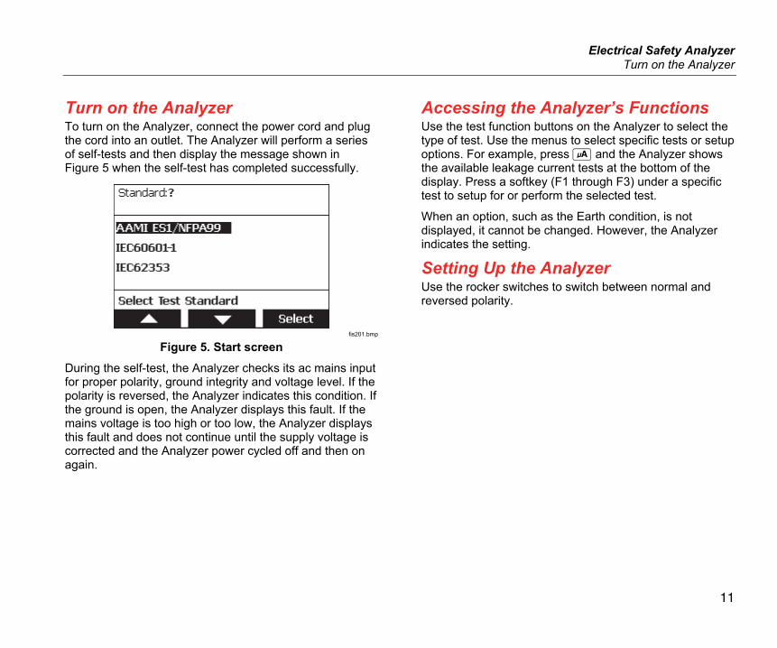
Turn on the Analyzer To turn on the Analyzer, connect the power cord and plug the cord into an outlet. The Analyzer will perform a series of self-tests and then display the message shown in Figure 5 when the self-test has completed successfully.
fis201.bmp
Figure 5. Start screen During the self-test, the Analyzer checks its ac mains input for proper polarity, ground integrity and voltage level. If the polarity is reversed, the Analyzer indicates this condition. If the ground is open, the Analyzer displays this fault. If the mains voltage is too high or too low, the Analyzer displays this fault and does not continue until the supply voltage is corrected and the Analyzer power cycled off and then on again.
Accessing the Analyzer’s Functions Use the test function buttons on the Analyzer to select the type of test. Use the menus to select specific tests or setup options. For example, press and the Analyzer shows the available leakage current tests at the bottom of the display. Press a softkey (F1 through F3) under a specific test to setup for or perform the selected test.
When an option, such as the Earth condition, is not displayed, it cannot be changed. However, the Analyzer indicates the setting.
Setting Up the Analyzer Use the rocker switches to switch between normal and reversed polarity.
ESA609 Users Manual
12
Performing Electrical Safety Tests The Analyzer performs a number of different electrical and performance tests on biomedical equipment. The following sections describe the various tests and how to perform them using the Analyzer.
Setting the Test Standard The Analyzer performs electrical safety testing based on a number of different safety standards: AAMI ES1/NFPA99, IEC 62353, and IEC 60601-1. AAMI is the Analyzer’s default standard.
To select another standard:
1. Press the softkey labeled Standard to open the scroll box above the softkey label.
2. Press or to scroll through the standard selections.
Some electrical tests may not be applicable for a specific standard. In these cases, the Analyzer’s menu will not display the excluded test as a selection.
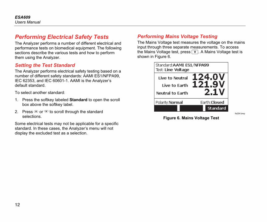
Performing Mains Voltage Testing The Mains Voltage test measures the voltage on the mains input through three separate measurements. To access the Mains Voltage test, press . A Mains Voltage test is shown in Figure 6.
fis204.bmp
Figure 6. Mains Voltage Test
Electrical Safety Analyzer Performing Electrical Safety Tests
13
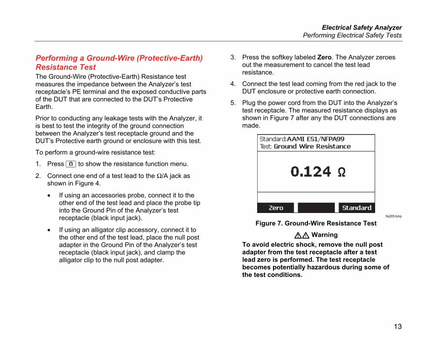
Performing a Ground-Wire (Protective-Earth) Resistance Test The Ground-Wire (Protective-Earth) Resistance test measures the impedance between the Analyzer’s test receptacle’s PE terminal and the exposed conductive parts of the DUT that are connected to the DUT’s Protective Earth.
Prior to conducting any leakage tests with the Analyzer, it is best to test the integrity of the ground connection between the Analyzer’s test receptacle ground and the DUT’s Protective earth ground or enclosure with this test.
To perform a ground-wire resistance test:
1. Press to show the resistance function menu.
2. Connect one end of a test lead to the Ω/A jack as shown in Figure 4.
• If using an accessories probe, connect it to the other end of the test lead and place the probe tip into the Ground Pin of the Analyzer’s test receptacle (black input jack).
• If using an alligator clip accessory, connect it to the other end of the test lead, place the null post adapter in the Ground Pin of the Analyzer’s test receptacle (black input jack), and clamp the alligator clip to the null post adapter.
3. Press the softkey labeled Zero. The Analyzer zeroes out the measurement to cancel the test lead resistance.
4. Connect the test lead coming from the red jack to the DUT enclosure or protective earth connection.
5. Plug the power cord from the DUT into the Analyzer’s test receptacle. The measured resistance displays as shown in Figure 7 after any the DUT connections are made.
fis205.bmp
Figure 7. Ground-Wire Resistance Test
Warning To avoid electric shock, remove the null post adapter from the test receptacle after a test lead zero is performed. The test receptacle becomes potentially hazardous during some of the test conditions.
ESA609 Users Manual
14
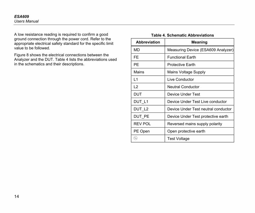
A low resistance reading is required to confirm a good ground connection through the power cord. Refer to the appropriate electrical safety standard for the specific limit value to be followed.
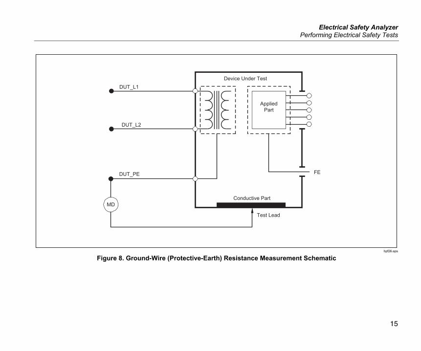
Figure 8 shows the electrical connections between the Analyzer and the DUT. Table 4 lists the abbreviations used in the schematics and their descriptions.
Table 4. Schematic Abbreviations
Abbreviation Meaning
MD Measuring Device (ESA609 Analyzer)
FE Functional Earth
PE Protective Earth
Mains Mains Voltage Supply
L1 Live Conductor
L2 Neutral Conductor
DUT Device Under Test
DUT_L1 Device Under Test Live conductor
DUT_L2 Device Under Test neutral conductor
DUT_PE Device Under Test protective earth
REV POL Reversed mains supply polarity
PE Open Open protective earth
Test Voltage
Electrical Safety Analyzer Performing Electrical Safety Tests
15
MD
Test Lead
Conductive Part
DUT_PE FE
DUT_L2
DUT_L1Device Under Test
AppliedPart
hpf26.eps
Figure 8. Ground-Wire (Protective-Earth) Resistance Measurement Schematic
ESA609 Users Manual
16
Performing a Current Consumption Test To measure the current consumed by the DUT, press . The Analyzer displays the current flowing through the mains connections of the test receptacle.
Performing Leakage Current Tests The Analyzer measures leakage current for a number of different DUT configurations.
The leakage tests that are available depend on which standard is selected. See the “Selecting the Test Standard” section earlier in this manual to change the standard the Analyzer is using.
Table 5 lists tests that have different names based on which standard is selected.
Table 5. Test Names Based on Selected Standard IEC60601 AAMI/NFPA 99
Protective-Earth Resistance
Ground-Wire Resistance
Earth-Leakage Current Ground-Wire Leakage Current
Touch- or Enclosure-Leakage Current
Chassis-Leakage Current
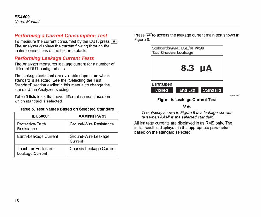
Press to access the leakage current main test shown in Figure 9.
fis217.bmp
Figure 9. Leakage Current Test
Note The display shown in Figure 9 is a leakage current test when AAMI is the selected standard.
All leakage currents are displayed in as RMS only. The initial result is displayed in the appropriate parameter based on the standard selected.
Electrical Safety Analyzer Performing Electrical Safety Tests
17
Measuring Ground-Wire (Earth) Leakage Current Note
The Ground-Wire (Earth) Leakage test is available for AAMI, 60601, and not IEC 62353.
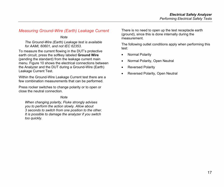
To measure the current flowing in the DUT’s protective earth circuit, press the softkey labeled Ground Wire (pending the standard) from the leakage current main menu. Figure 10 shows the electrical connections between the Analyzer and the DUT during a Ground-Wire (Earth) Leakage Current Test.
Within the Ground-Wire Leakage Current test there are a few combination measurements that can be performed.
Press rocker switches to change polarity or to open or close the neutral connection.
Note When changing polarity, Fluke strongly advises you to perform the action slowly. Allow about 3 seconds to switch from one position to the other. It is possible to damage the analyzer if you switch too quickly.
There is no need to open up the test receptacle earth (ground), since this is done internally during the measurement.
The following outlet conditions apply when performing this test:
• Normal Polarity
• Normal Polarity, Open Neutral
• Reversed Polarity
• Reversed Polarity, Open Neutral
ESA609 Users Manual
18
Conductive Part
DUT_PE
PE
DUT_L2
DUT_L1
L2
REVPOL
MD
Device Under Test
hpf27.eps
Figure 10. Earth-Leakage Current Test Schematic
Electrical Safety Analyzer Performing Electrical Safety Tests
19
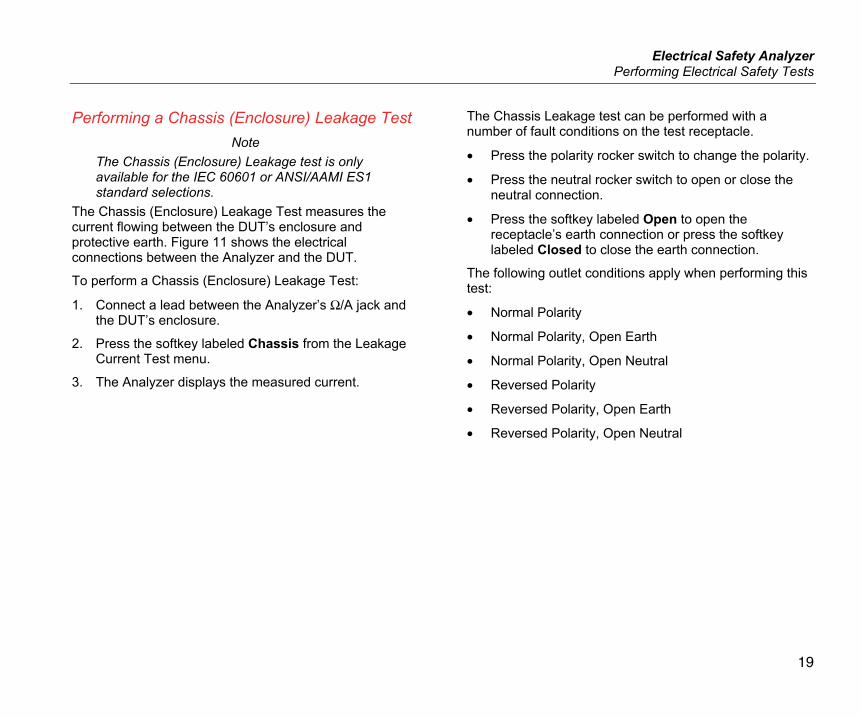
Performing a Chassis (Enclosure) Leakage Test Note
The Chassis (Enclosure) Leakage test is only available for the IEC 60601 or ANSI/AAMI ES1 standard selections.
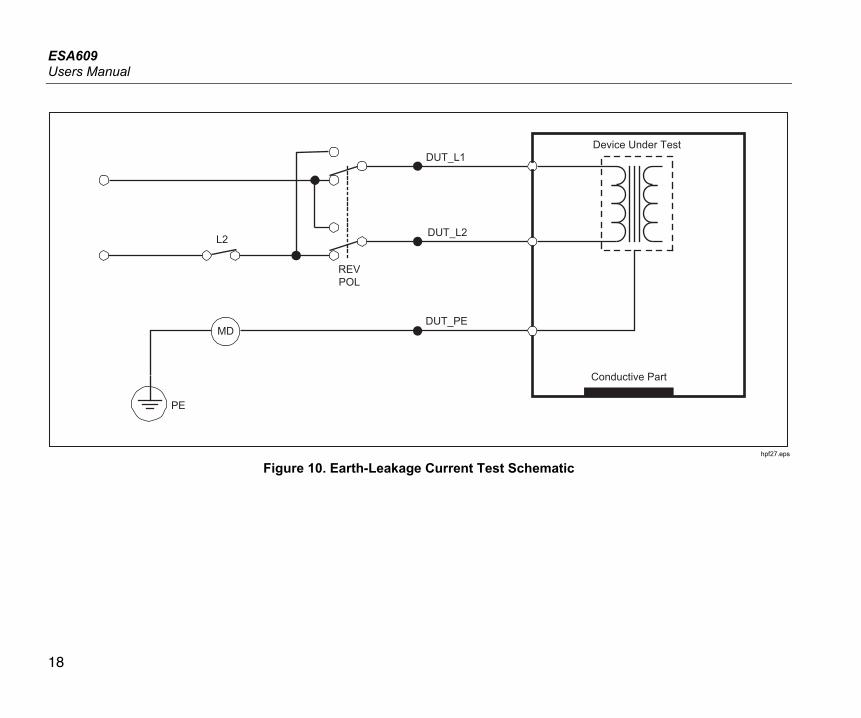
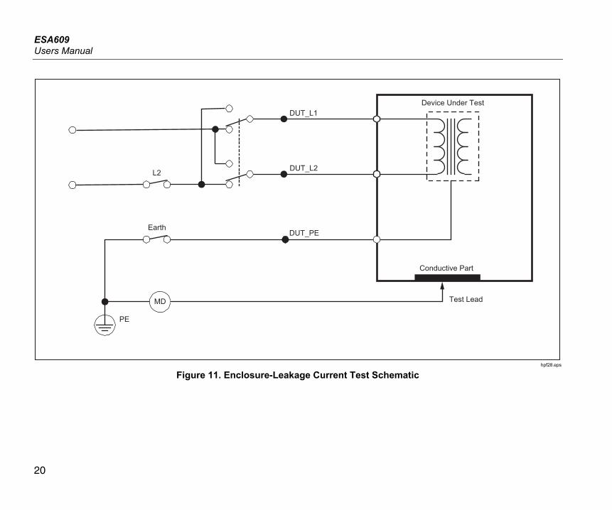
The Chassis (Enclosure) Leakage Test measures the current flowing between the DUT’s enclosure and protective earth. Figure 11 shows the electrical connections between the Analyzer and the DUT.
To perform a Chassis (Enclosure) Leakage Test:
1. Connect a lead between the Analyzer’s Ω/A jack and the DUT’s enclosure.
2. Press the softkey labeled Chassis from the Leakage Current Test menu.
3. The Analyzer displays the measured current.
The Chassis Leakage test can be performed with a number of fault conditions on the test receptacle.
• Press the polarity rocker switch to change the polarity.
• Press the neutral rocker switch to open or close the neutral connection.
• Press the softkey labeled Open to open the receptacle’s earth connection or press the softkey labeled Closed to close the earth connection.
The following outlet conditions apply when performing this test:
• Normal Polarity
• Normal Polarity, Open Earth
• Normal Polarity, Open Neutral
• Reversed Polarity
• Reversed Polarity, Open Earth
• Reversed Polarity, Open Neutral
ESA609 Users Manual
20
Conductive Part
DUT_PE
Test Lead
PE
DUT_L2
DUT_L1
Earth
L2
MD
Device Under Test
hpf28.eps
Figure 11. Enclosure-Leakage Current Test Schematic
Electrical Safety Analyzer Performing Electrical Safety Tests
21
Performing a Direct-Equipment Leakage Test Note
The Direct-Equipment Leakage test is available when the EN62353 standard is selected.
The Direct-Equipment Leakage Current test measures the leakage current between the exposed conductive surface on the housing, to mains earth.
To perform a direct-equipment test, press .
The direct-equipment test is the default test and should already be selected.
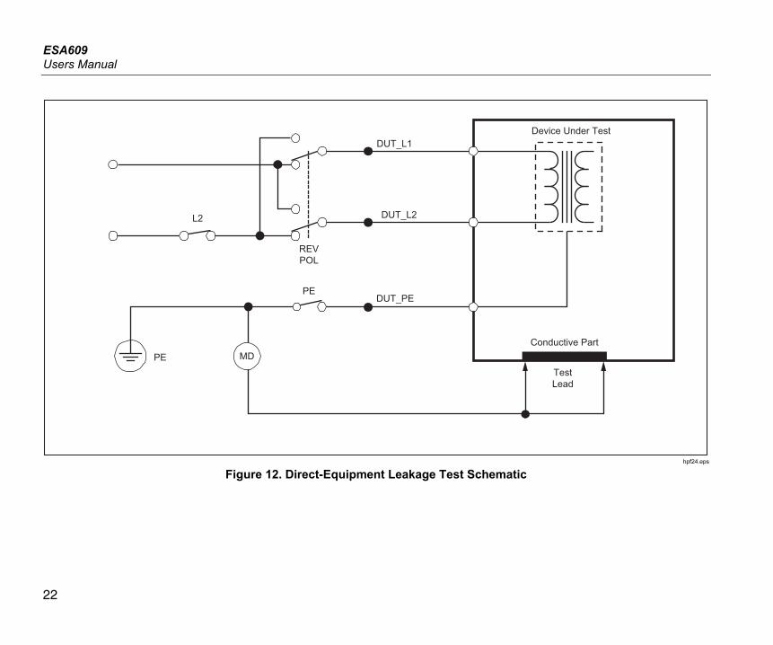
Figure 12 shows the electrical connections between the Analyzer and the DUT during a Direct-Equipment Leakage Current Test.
The following outlet conditions apply when performing this test:
• Normal Polarity, Closed Earth
• Normal Polarity, Open Earth
• Reversed Polarity, Closed Earth
• Reversed Polarity, Open Earth
ESA609 Users Manual
22
Conductive Part
DUT_PE
DUT_L2
DUT_L1
L2
REVPOL
PE
PETestLead
Device Under Test
MD
hpf24.eps
Figure 12. Direct-Equipment Leakage Test Schematic
Electrical Safety Analyzer Making Point-To-Point Measurements
23
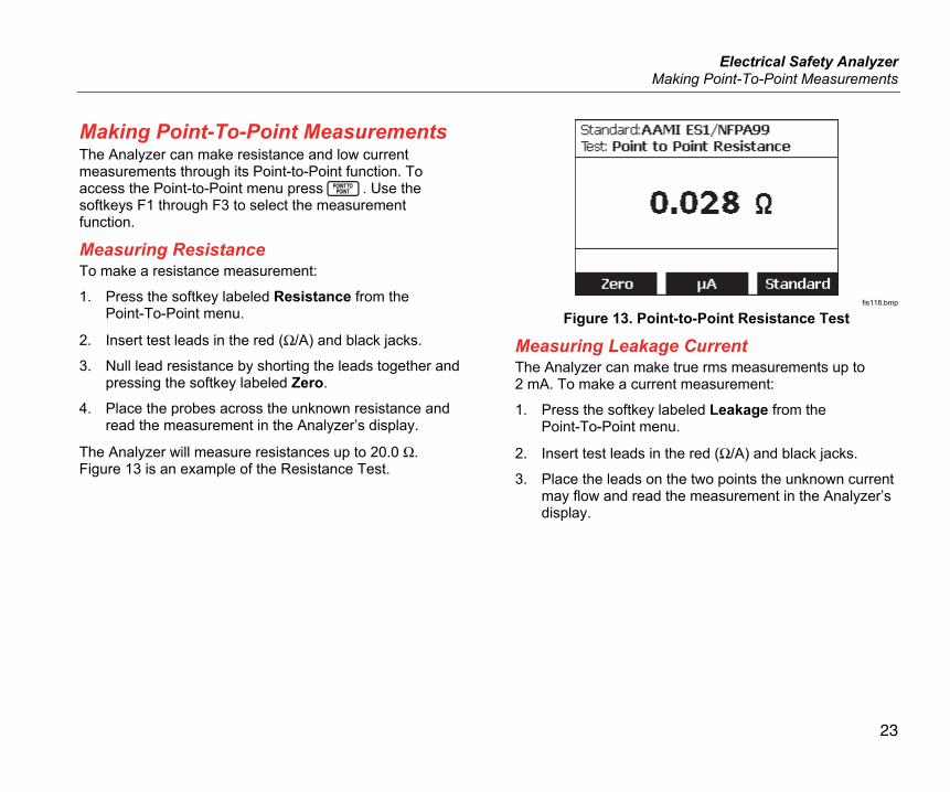
Making Point-To-Point Measurements The Analyzer can make resistance and low current measurements through its Point-to-Point function. To access the Point-to-Point menu press . Use the softkeys F1 through F3 to select the measurement function.
Measuring Resistance To make a resistance measurement:
1. Press the softkey labeled Resistance from the Point-To-Point menu.
2. Insert test leads in the red (Ω/A) and black jacks.
3. Null lead resistance by shorting the leads together and pressing the softkey labeled Zero.
4. Place the probes across the unknown resistance and read the measurement in the Analyzer’s display.
The Analyzer will measure resistances up to 20.0 Ω. Figure 13 is an example of the Resistance Test.
fis118.bmp
Figure 13. Point-to-Point Resistance Test
Measuring Leakage Current The Analyzer can make true rms measurements up to 2 mA. To make a current measurement:
1. Press the softkey labeled Leakage from the Point-To-Point menu.
2. Insert test leads in the red (Ω/A) and black jacks.
3. Place the leads on the two points the unknown current may flow and read the measurement in the Analyzer’s display.
ESA609 Users Manual
24
Maintenance The Analyzer needs little maintenance or special care. However, treat it as a calibrated measuring instrument. Avoid dropping or other mechanical abuse that could cause a shift in the calibrated settings.
Warning To prevent possible electrical shock, fire, or personal injury: • Remove the mains power cord. Stop for
two minutes to let the power assemblies discharge before you open the fuse door.
• Replace a blown fuse with exact replacement only for continued protection against arc flash.
• Do not operate the Product with covers removed or the case open. Hazardous voltage exposure is possible.
• Disconnect the mains power cord before you remove the Product covers.
• Remove the input signals before you clean the Product.
• Use only specified replacement parts. • Use only specified replacement fuses. • Have an approved technician repair the
Product.
Testing and Replacing the Fuses For electrical protection of the equipment outlet, the Analyzer uses one fuse in the live (L1) line and one fuse in the neutral (L2) line.
To test the fuses, do the following while referring to Figure 14:
1. Remove the holster.
2. Remove the fuse door from the Analyzer by removing the screw holding the fuse door with a #2 Phillips head screwdriver and lifting the fuse door from the Analyzer.
3. Remove the fuses from the Analyzer.
4. Using a multimeter, measure the continuity of each fuse.
If one or both fuses do not show continuity, replace the fuse(s) with fuses that have the same current and voltage rating. Appropriate fuse ratings are posted on the case bottom label of the Analyzer. Table 6 lists available fuses with Fluke Biomedical part numbers.
5. Reinstall the fuse door and secure it with the screw.

Electrical Safety Analyzer Maintenance
25
F1 - F2
hpf111.eps
Figure 14. Fuse Access
Cleaning the Analyzer Warning
To avoid electric shock, do not clean the Analyzer plugged into mains or attached to a DUT.
Caution Do not pour fluid onto the Analyzer surface; fluid seepage into the electrical circuitry may cause the Analyzer to fail.
Caution Do not use spray cleaners on the Analyzer; such action may force cleaning fluid into the Analyzer and damage electronic components.
Clean the Analyzer occasionally utilizing a damp cloth and mild detergent. Take care to prevent the entrance of liquids.
Wipe down the adapter cables with the same care. Inspect them for damage to and deterioration of the insulation. Check the connections for integrity before each use.
ESA609 Users Manual
26
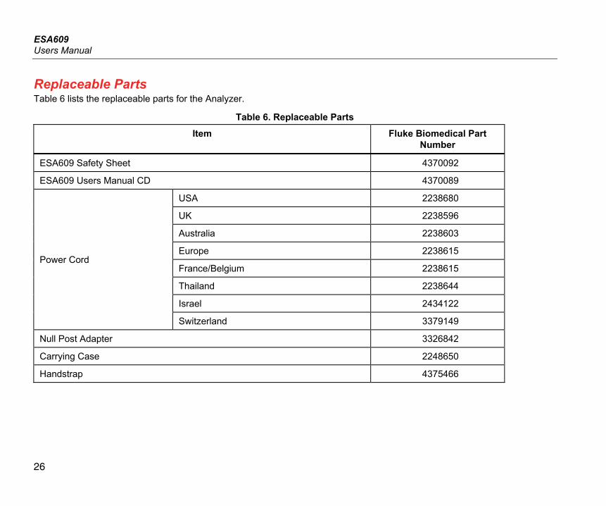
Replaceable Parts Table 6 lists the replaceable parts for the Analyzer.
Table 6. Replaceable Parts
Item Fluke Biomedical Part Number
ESA609 Safety Sheet 4370092
ESA609 Users Manual CD 4370089
Power Cord
USA 2238680
UK 2238596
Australia 2238603
Europe 2238615
France/Belgium 2238615
Thailand 2238644
Israel 2434122
Switzerland 3379149
Null Post Adapter 3326842
Carrying Case 2248650
Handstrap 4375466
Electrical Safety Analyzer Replaceable Parts
27
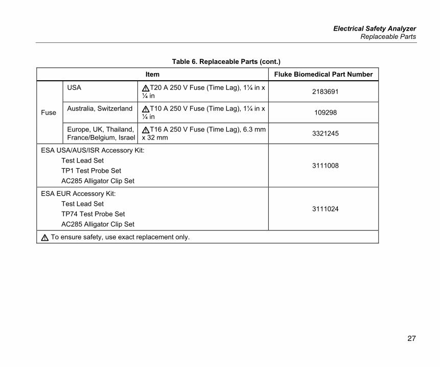
Table 6. Replaceable Parts (cont.)
Item Fluke Biomedical Part Number
Fuse
USA T20 A 250 V Fuse (Time Lag), 1¼ in x ¼ in 2183691
Australia, Switzerland T10 A 250 V Fuse (Time Lag), 1¼ in x ¼ in 109298
Europe, UK, Thailand, France/Belgium, Israel
T16 A 250 V Fuse (Time Lag), 6.3 mm x 32 mm 3321245
ESA USA/AUS/ISR Accessory Kit: Test Lead Set TP1 Test Probe Set AC285 Alligator Clip Set
3111008
ESA EUR Accessory Kit: Test Lead Set TP74 Test Probe Set AC285 Alligator Clip Set
3111024
To ensure safety, use exact replacement only.
ESA609 Users Manual
28
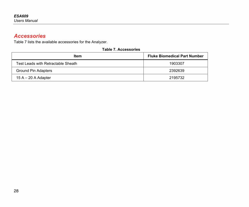
Accessories Table 7 lists the available accessories for the Analyzer.
Table 7. Accessories Item Fluke Biomedical Part Number
Test Leads with Retractable Sheath 1903307
Ground Pin Adapters 2392639
15 A – 20 A Adapter 2195732
Electrical Safety Analyzer Specifications
29
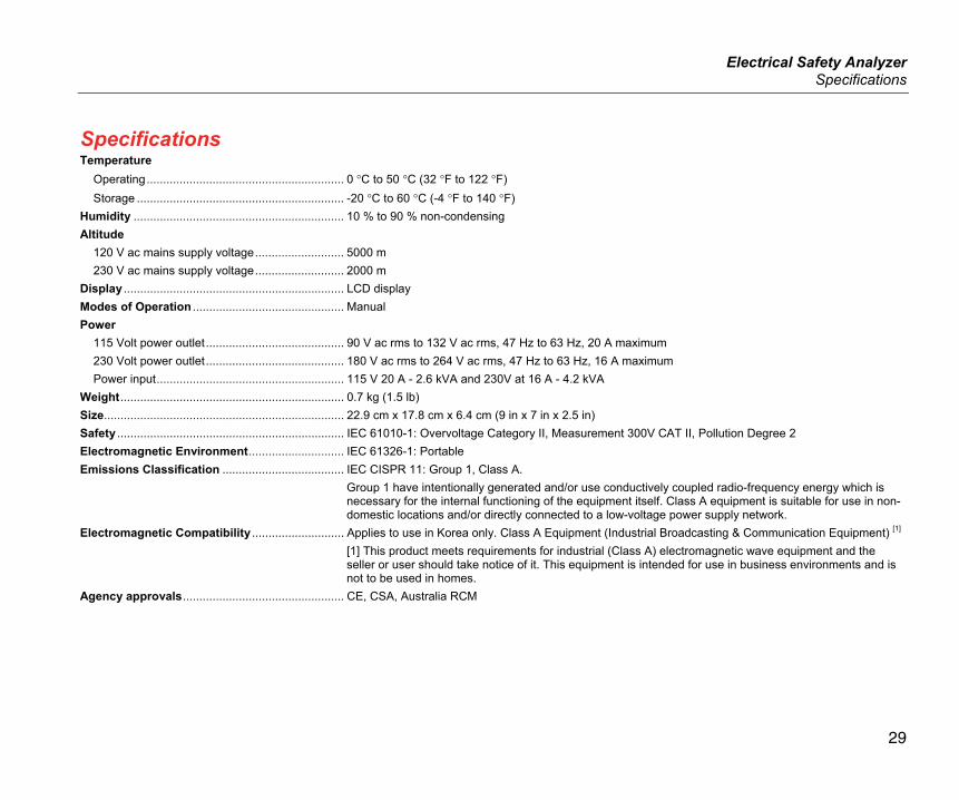
Specifications Temperature
Operating ............................................................ 0 °C to 50 °C (32 °F to 122 °F) Storage ............................................................... -20 °C to 60 °C (-4 °F to 140 °F)
Humidity ................................................................ 10 % to 90 % non-condensing Altitude
120 V ac mains supply voltage ........................... 5000 m 230 V ac mains supply voltage ........................... 2000 m
Display ................................................................... LCD display Modes of Operation .............................................. Manual Power
115 Volt power outlet .......................................... 90 V ac rms to 132 V ac rms, 47 Hz to 63 Hz, 20 A maximum 230 Volt power outlet .......................................... 180 V ac rms to 264 V ac rms, 47 Hz to 63 Hz, 16 A maximum Power input ......................................................... 115 V 20 A - 2.6 kVA and 230V at 16 A - 4.2 kVA
Weight .................................................................... 0.7 kg (1.5 lb) Size ......................................................................... 22.9 cm x 17.8 cm x 6.4 cm (9 in x 7 in x 2.5 in) Safety ..................................................................... IEC 61010-1: Overvoltage Category II, Measurement 300V CAT II, Pollution Degree 2 Electromagnetic Environment ............................. IEC 61326-1: Portable Emissions Classification ..................................... IEC CISPR 11: Group 1, Class A.
Group 1 have intentionally generated and/or use conductively coupled radio-frequency energy which is necessary for the internal functioning of the equipment itself. Class A equipment is suitable for use in non-domestic locations and/or directly connected to a low-voltage power supply network.
Electromagnetic Compatibility ............................ Applies to use in Korea only. Class A Equipment (Industrial Broadcasting & Communication Equipment) [1] [1] This product meets requirements for industrial (Class A) electromagnetic wave equipment and the seller or user should take notice of it. This equipment is intended for use in business environments and is not to be used in homes.
Agency approvals ................................................. CE, CSA, Australia RCM
ESA609 Users Manual
30
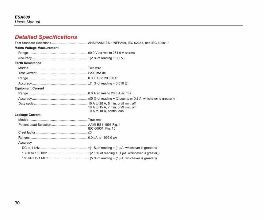
Detailed Specifications Test Standard Selections ........................................ ANSI/AAMI ES-1/NFPA99, IEC 62353, and IEC 60601-1 Mains Voltage Measurement
Range ................................................................. 90.0 V ac rms to 264.0 V ac rms Accuracy ............................................................. ±(2 % of reading + 0.2 V)
Earth Resistance Modes ................................................................. Two wire Test Current ........................................................ >200 mA dc Range ................................................................. 0.000 Ω to 20.000 Ω Accuracy ............................................................. ±(1 % of reading + 0.010 Ω)
Equipment Current Range ................................................................. 0.0 A ac rms to 20.0 A ac rms Accuracy ............................................................. ±(5 % of reading + (2 counts or 0.2 A, whichever is greater)) Duty cycle ........................................................... 15 A to 20 A, 5 min. on/5 min. off
10 A to 15 A, 7 min. on/3 min. off 0 A to 10 A, continuous
Leakage Current Modes ................................................................. True-rms Patient Load Selection ........................................ AAMI ES1-1993 Fig. 1
IEC 60601: Fig. 15 Crest factor ......................................................... ≤3 Ranges ............................................................... 0.0 μA to 1999.9 μA Accuracy
DC to 1 kHz .................................................... ±(1 % of reading + (1 μA, whichever is greater)) 1 kHz to 100 kHz ............................................ ±(2.5 % of reading + (1 μA, whichever is greater)) 100 kHz to 1 MHz ........................................... ±(5 % of reading + (1 μA, whichever is greater))
Related Documents