ESA620 Electrical Safety Analyzer Getting Started Manual PN 2814971 January 2008 © 2008 Fluke Corporation. All rights reserved. Printed in USA. Specifications subject to change without notice. All product names are trademarks of their respective companies.

Welcome message from author
This document is posted to help you gain knowledge. Please leave a comment to let me know what you think about it! Share it to your friends and learn new things together.
Transcript

ESA620 Electrical Safety Analyzer
Getting Started Manual
PN 2814971 January 2008 © 2008 Fluke Corporation. All rights reserved. Printed in USA. Specifications subject to change without notice. All product names are trademarks of their respective companies.

Warranty and Product Support
Fluke Biomedical warrants this instrument against defects in materials and workmanship for one year from the date of origi-nal purchase. During the warranty period, we will repair or at our option replace, at no charge, a product that proves to be defective, provided you return the product, shipping prepaid, to Fluke Biomedical. This warranty covers the original pur-chaser only and is not transferable. The warranty does not apply if the product has been damaged by accident or misuse or has been serviced or modified by anyone other than an authorized Fluke Biomedical service facility. NO OTHER WARRAN-TIES, SUCH AS FITNESS FOR A PARTICULAR PURPOSE, ARE EXPRESSED OR IMPLIED. FLUKE SHALL NOT BE LIABLE FOR ANY SPECIAL, INDIRECT, INCIDENTAL OR CONSEQUENTIAL DAMAGES OR LOSSES, INCLUDING LOSS OF DATA, ARISING FROM ANY CAUSE OR THEORY.
This warranty covers only serialized products and their accessory items that bear a distinct serial number tag. Recalibration of instruments is not covered under the warranty
This warranty gives you specific legal rights and you may also have other rights that vary in different jurisdictions. Since some jurisdictions do not allow the exclusion or limitation of an implied warranty or of incidental or consequential damages, this limitation of liability may not apply to you. If any provision of this warranty is held invalid or unenforceable by a court or other decision-maker of competent jurisdiction, such holding will not affect the validity or enforceability of any other provision.
7/07

Notices
All Rights Reserved © Copyright 2008, Fluke Biomedical. No part of this publication may be reproduced, transmitted, transcribed, stored in a retrieval system, or translated into any language without the written permission of Fluke Biomedical.
Copyright Release Fluke Biomedical agrees to a limited copyright release that allows you to reproduce manuals and other printed materials for use in service training programs and other technical publications. If you would like other reproductions or distributions, submit a written request to Fluke Biomedical.
Unpacking and Inspection Follow standard receiving practices upon receipt of the instrument. Check the shipping carton for damage. If damage is found, stop unpacking the instrument. Notify the carrier and ask for an agent to be present while the instrument is unpacked. There are no special unpacking instructions, but be careful not to dam-age the instrument when unpacking it. Inspect the instrument for physical damage such as bent or broken parts, dents, or scratches.
Technical Support For application support or answers to technical questions, either email [email protected] or call 1-800- 648-7952 or 1-425-446-6945.
Claims Our routine method of shipment is via common carrier, FOB origin. Upon delivery, if physical damage is found, retain all packing materials in their original condition and contact the carrier immediately to file a claim. If the instrument is delivered in good physical condition but does not operate within specifica-tions, or if there are any other problems not caused by shipping damage, please contact Fluke Biomedical or your local sales representative.

Standard Terms and Conditions Refunds and Credits
Please note that only serialized products and their accessory items (i.e., products and items bearing a distinct serial number tag) are eligible for partial refund and/or credit. Nonserialized parts and accessory items (e.g., cables, carrying cases, auxiliary modules, etc.) are not eligible for re-turn or refund. Only products returned within 90 days from the date of original purchase are eligible for refund/credit. In order to receive a partial re-fund/credit of a product purchase price on a serialized product, the product must not have been damaged by the customer or by the carrier chosen by the cus-tomer to return the goods, and the product must be returned complete (meaning with all manuals, cables, accessories, etc.) and in “as new” and resalable con-dition. Products not returned within 90 days of purchase, or products which are not in “as new” and resalable condition, are not eligible for credit return and will be returned to the customer. The Return Procedure (see below) must be followed to assure prompt refund/credit.
Restocking Charges Products returned within 30 days of original purchase are subject to a minimum restocking fee of 15 %. Products returned in excess of 30 days af-ter purchase, but prior to 90 days, are subject to a minimum restocking fee of 20 %. Additional charges for damage and/or missing parts and accesso-ries will be applied to all returns.
Return Procedure All items being returned (including all warranty-claim shipments) must be sent freight-prepaid to our factory location. When you return an instrument to Fluke Biomedical, we recommend using United Parcel Service, Federal Express, or Air Parcel Post. We also recommend that you insure your shipment for its actual replacement cost. Fluke Biomedical will not be responsible for lost shipments or instruments that are received in damaged condition due to improper packaging or handling. Use the original carton and packaging material for shipment. If they are not available, we recommend the following guide for repackaging:
Use a double–walled carton of sufficient strength for the weight being shipped. Use heavy paper or cardboard to protect all instrument surfaces. Use nonabrasive material around all projecting parts. Use at least four inches of tightly packed, industry-approved, shock-absorbent material around the instrument.
Returns for partial refund/credit: Every product returned for refund/credit must be accompanied by a Return Material Authorization (RMA) number, obtained from our Order Entry Group at 1-800-648-7952 or 1-425-446-6945. Repair and calibration: To find the nearest service center, go to www.flukebiomedical.com/service or In the U.S.A.: Cleveland Calibration Lab Tel: 1-800-850-4606 Email: [email protected] Everett Calibration Lab Tel: 1-888-99 FLUKE (1-888-993-5853) Email: [email protected] In Europe, Middle East, and Africa: Eindhoven Calibration Lab Tel: +31-402-675300 Email: [email protected] In Asia: Everett Calibration Lab Tel: +425-446-6945 Email: [email protected]
Certification This instrument was thoroughly tested and inspected. It was found to meet Fluke Biomedical’s manufacturing specifications when it was shipped from the factory. Calibration measurements are traceable to the National Institute of Standards and Technology (NIST). Devices for which there are no NIST calibra-tion standards are measured against in-house performance standards using accepted test procedures.
WARNING Unauthorized user modifications or application beyond the published specifications may result in electrical shock hazards or improper operation. Fluke Bio-medical will not be responsible for any injuries sustained due to unauthorized equipment modifications.

Restrictions and Liabilities Information in this document is subject to change and does not represent a commitment by Fluke Biomedical. Changes made to the information in this document will be incorporated in new editions of the publication. No responsibility is assumed by Fluke Biomedical for the use or reliability of software or equipment that is not supplied by Fluke Biomedical, or by its affiliated dealers.
Manufacturing Location The ESA620 Electrical Safety Analyzer is manufactured at Fluke Biomedical, 6920 Seaway Blvd., Everett, WA, U.S.A.
i
Table of Contents
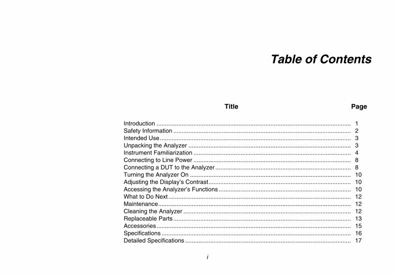
Title Page Introduction .................................................................................................................... 1 Safety Information .......................................................................................................... 2 Intended Use.................................................................................................................. 3 Unpacking the Analyzer ................................................................................................. 3 Instrument Familiarization .............................................................................................. 4 Connecting to Line Power .............................................................................................. 8 Connecting a DUT to the Analyzer ................................................................................. 8 Turning the Analyzer On ................................................................................................ 10 Adjusting the Display’s Contrast..................................................................................... 10 Accessing the Analyzer’s Functions ............................................................................... 10 What to Do Next ............................................................................................................. 12 Maintenance................................................................................................................... 12 Cleaning the Analyzer .................................................................................................... 12 Replaceable Parts .......................................................................................................... 13 Accessories .................................................................................................................... 15 Specifications ................................................................................................................. 16 Detailed Specifications ................................................................................................... 17

ESA620 Getting Started Manual
ii

iii
List of Tables
Table Title Page
1. Symbols................................................................................................................................. 2 2. Top-Panel Controls and Connections.................................................................................... 6 3. Rear-Panel Connections ....................................................................................................... 8 4. Replaceable Parts ................................................................................................................. 13 5. Accessories ........................................................................................................................... 15

ESA620 Getting Started Manual
iv
v
List of Figures
Figure Title Page
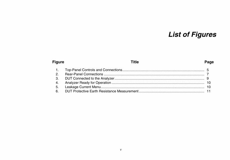
1. Top-Panel Controls and Connections.................................................................................... 5 2. Rear-Panel Connections ....................................................................................................... 7 3. DUT Connected to the Analyzer............................................................................................ 9 4. Analyzer Ready for Operation ............................................................................................... 10 5. Leakage Current Menu.......................................................................................................... 10 6. DUT Protective Earth Resistance Measurement ................................................................... 11

ESA620 Getting Started Manual
vi

1
Electrical Safety Analyzer
Introduction The Fluke Biomedical ESA620 Electrical Safety Analyzer (hereafter the Analyzer) is a full-featured, compact, portable analyzer, designed to verify the electrical safety of medical devices. The Analyzer tests to international (IEC 60601-1, EN62353, AN/NZS 3551, IEC61010, VDE 751) and domestic (ANSI/AAMI ES1, NFPA 99) electrical-safety standards. The integrated ANSI/AAMI ES1, IEC60601-1, and IEC61010 patient loads are easily selectable.
The Analyzer performs the following tests:
• Mains (Line) voltage
• Protective Earth (or Ground Wire) Resistance
• Equipment current
• Insulation resistance
• Earth (Ground) leakage
• Enclosure (Chassis) leakage
• Patient (Lead to Ground) and patient auxiliary (Lead to Lead) leakage
• Mains on applied parts leakage (Lead isolation)
• Differential leakage
• Direct equipment leakage
• Direct applied part leakage
• Alternative equipment leakage
• Alternative applied part patient leakage
• Accessible part leakage
• Accessible part voltage
• Point to point leakage, voltage, and resistance
• ECG simulation and performance waveforms

ESA620 Getting Started Manual
2
Table 1. Symbols
Symbol Description
W Important information; refer to manual.
X Hazardous voltage
) Conforms to relevant Canadian and US standards
; Conforms to relevant Australian EMC requirements
P Conforms to European Union directives
~ Do not dispose of this product as unsorted municipal waste. Go to Fluke’s website for recycling information.
CAT II
IEC Measurement Category II – CAT II equipment designed to protect against transients from energy-consuming equipment supplied from fixed installations. Under no circumstances should the terminals of the Analyzer be connected to any MAINS voltage.
Safety Information In this manual, a Warning identifies hazardous conditions and actions that could cause bodily harm or death. A Caution identifies conditions and actions that could damage the Analyzer, the equipment under test, or cause permanent loss of data.
XW Warning To avoid possible electrical shock or personal injury, follow these guidelines:
• Use this Analyzer only in the manner specified by the manufacturer or the protection provided may be impaired.
• Read the Users Manual before operating the Analyzer.
• Do not connect the Analyzer to a patient or equipment connected to a patient. The Analyzer is intended for equipment evaluation only and should never be used in diagnostics, treatment or in any other capacity where the Analyzer would come in contact with a patient.
• Do not use the product in wet locations, around explosive gases or dust.
Electrical Safety Analyzer Intended Use
3
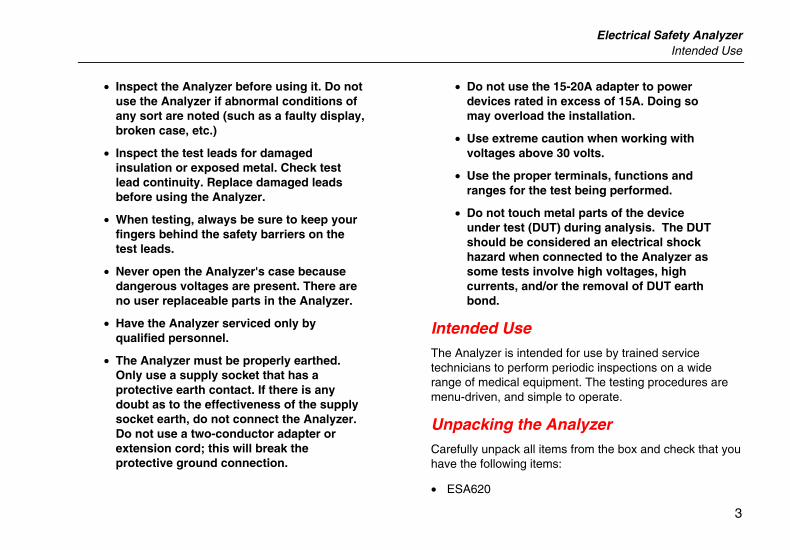
• Inspect the Analyzer before using it. Do not use the Analyzer if abnormal conditions of any sort are noted (such as a faulty display, broken case, etc.)
• Inspect the test leads for damaged insulation or exposed metal. Check test lead continuity. Replace damaged leads before using the Analyzer.
• When testing, always be sure to keep your fingers behind the safety barriers on the test leads.
• Never open the Analyzer's case because dangerous voltages are present. There are no user replaceable parts in the Analyzer.
• Have the Analyzer serviced only by qualified personnel.
• The Analyzer must be properly earthed. Only use a supply socket that has a protective earth contact. If there is any doubt as to the effectiveness of the supply socket earth, do not connect the Analyzer. Do not use a two-conductor adapter or extension cord; this will break the protective ground connection.
• Do not use the 15-20A adapter to power devices rated in excess of 15A. Doing so may overload the installation.
• Use extreme caution when working with voltages above 30 volts.
• Use the proper terminals, functions and ranges for the test being performed.
• Do not touch metal parts of the device under test (DUT) during analysis. The DUT should be considered an electrical shock hazard when connected to the Analyzer as some tests involve high voltages, high currents, and/or the removal of DUT earth bond.
Intended Use The Analyzer is intended for use by trained service technicians to perform periodic inspections on a wide range of medical equipment. The testing procedures are menu-driven, and simple to operate.
Unpacking the Analyzer Carefully unpack all items from the box and check that you have the following items:
• ESA620

ESA620 Getting Started Manual
4
• Getting Started Manual
• Users Manual CD
• Carrying case
• Power cord
• 15 – 20 A Adapter (USA only)
• Test lead set
• TP1 Test probe set (US, Australia, and Israel only)
• TP74 Test probe set (Europe only)
• Ansur demo CD
• Alligator clip set
Instrument Familiarization Figure 1 and Table 2 describes the top-panel controls and connections of the Analyzer.

Electrical Safety Analyzer Instrument Familiarization
5
POLARITY
NEUTRAL
EARTH
TESTF1 F2 F3 F4 F5
STANDARDS
POINT TOPOINT
SETUP
M
230 VAC
ESA620 ELECTRICAL SAFETY ANALYZER
RA LL LA RL V1 V2 V3 V4 V5 V6R F L N C1 C2 C3 C4 C5 C6
1
8
2
3
4
9 5
67
10
faw02.eps
Figure 1. Top-Panel Controls and Connections
ESA620 Getting Started Manual
6
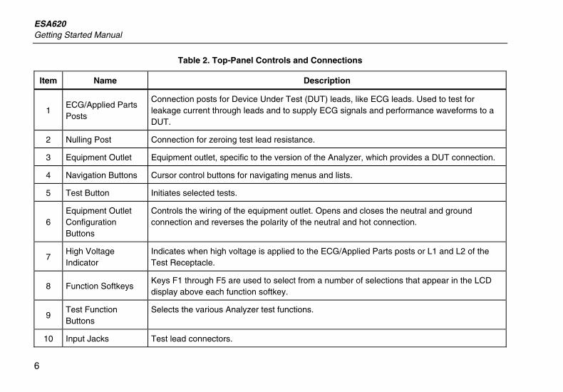
Table 2. Top-Panel Controls and Connections
Item Name Description
1 ECG/Applied Parts Posts
Connection posts for Device Under Test (DUT) leads, like ECG leads. Used to test for leakage current through leads and to supply ECG signals and performance waveforms to a DUT.
2 Nulling Post Connection for zeroing test lead resistance.
3 Equipment Outlet Equipment outlet, specific to the version of the Analyzer, which provides a DUT connection.
4 Navigation Buttons Cursor control buttons for navigating menus and lists.
5 Test Button Initiates selected tests.
6 Equipment Outlet Configuration Buttons
Controls the wiring of the equipment outlet. Opens and closes the neutral and ground connection and reverses the polarity of the neutral and hot connection.
7 High Voltage Indicator
Indicates when high voltage is applied to the ECG/Applied Parts posts or L1 and L2 of the Test Receptacle.
8 Function Softkeys Keys F1 through F5 are used to select from a number of selections that appear in the LCD display above each function softkey.
9 Test Function Buttons
Selects the various Analyzer test functions.
10 Input Jacks Test lead connectors.
Electrical Safety Analyzer Instrument Familiarization
7
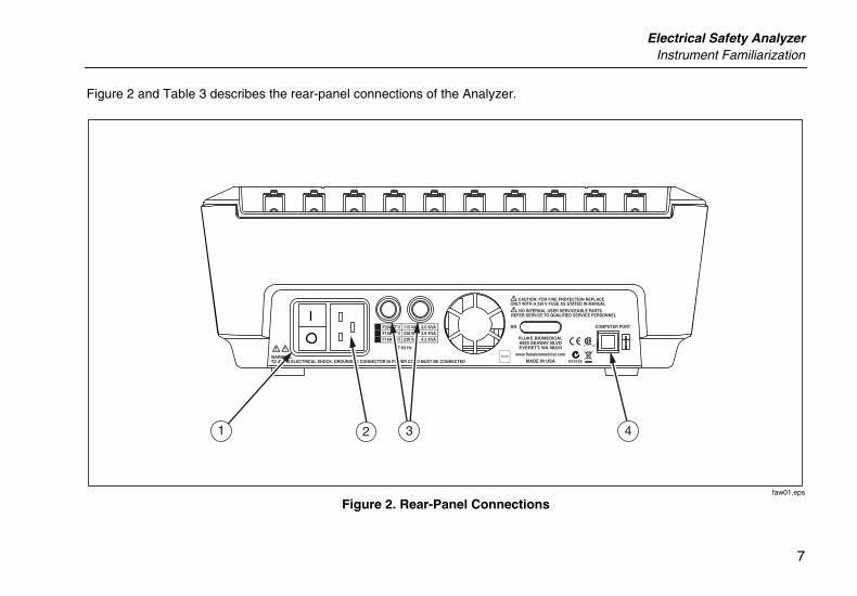
Figure 2 and Table 3 describes the rear-panel connections of the Analyzer.
1 2 43
faw01.eps
Figure 2. Rear-Panel Connections
ESA620 Getting Started Manual
8
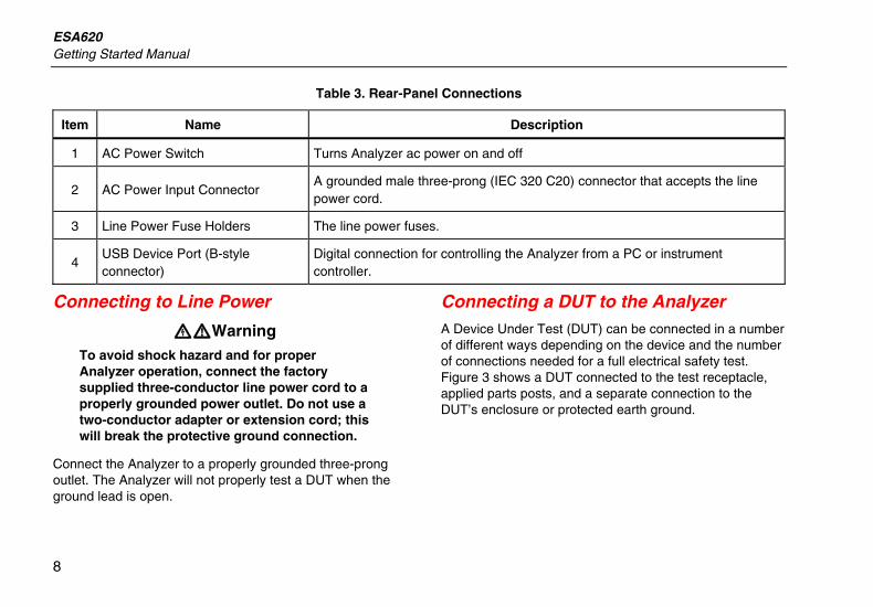
Table 3. Rear-Panel Connections
Item Name Description
1 AC Power Switch Turns Analyzer ac power on and off
2 AC Power Input Connector A grounded male three-prong (IEC 320 C20) connector that accepts the line power cord.
3 Line Power Fuse Holders The line power fuses.
4 USB Device Port (B-style connector)
Digital connection for controlling the Analyzer from a PC or instrument controller.
Connecting to Line Power
XWWarning To avoid shock hazard and for proper Analyzer operation, connect the factory supplied three-conductor line power cord to a properly grounded power outlet. Do not use a two-conductor adapter or extension cord; this will break the protective ground connection.
Connect the Analyzer to a properly grounded three-prong outlet. The Analyzer will not properly test a DUT when the ground lead is open.
Connecting a DUT to the Analyzer A Device Under Test (DUT) can be connected in a number of different ways depending on the device and the number of connections needed for a full electrical safety test. Figure 3 shows a DUT connected to the test receptacle, applied parts posts, and a separate connection to the DUT’s enclosure or protected earth ground.

Electrical Safety Analyzer Connecting a DUT to the Analyzer
9
To protective earth or enclosure
faw03.eps
Figure 3. DUT Connected to the Analyzer

ESA620 Getting Started Manual
10
Turning the Analyzer On
Note
To ensure the high voltage indicator is working, look for it to illuminate during the power-up self test.
Press the power switch on the rear panel so the “I” side of the ac power switch is depressed. The Analyzer will perform a series of self tests and then display the message shown in Figure 4 when the self test has completed successfully.
faw05.eps
Figure 4. Analyzer Ready for Operation
During the self-test, the Analyzer checks its ac mains input for proper polarity, ground integrity and voltage level. The high voltage indicator illuminates briefly during the self test. If the polarity is reversed, the Analyzer indicates this condition and allows the polarity to be reversed internally. If the ground is open, the Analyzer displays this fault. If the mains voltage is too high or too
low, the Analyzer displays this fault and does not continue until the supply voltage is corrected and the ESA620 power cycled off and then on again.
Adjusting the Display’s Contrast While the Analyzer displays the start-up menu shown in figure 4, press G or H to increase or decrease the display’s contrast. Press the softkey labeled Done to exit contrast setup.
Accessing the Analyzer’s Functions For each test and setup function, the Analyzer uses a series of menus to access various Analyzer tests and setup variables. As shown in Figure 5, the Analyzer indicates various leakage current tests along the bottom of the display. An Exit selection is also indicated as a way of backing out of the leakage current tests. Pressing a softkey (F1 through F5) under a specific test will cause the analyzer to setup for or perform the selected test.
faw04.eps
Figure 5. Leakage Current Menu
Electrical Safety Analyzer Accessing the Analyzer’s Functions
11
In addition to the function softkeys, the Analyzer test functions may require using the navigation buttons to select parameters as well. In the example above, the leakage selection has K next to it. This icon indicates the selection is controlled by pressing G or H. In this example, the leakage current measurement is switched between AC+DC, AC only, or DC only. The applied parts indicator has W on the left end and X on the right end. These icons indicate the use of E and F to select an applied part.
The three buttons along the right side of the display (PND) control the wiring of the Analyzer’s test receptacle for some electrical tests. The present state of these three buttons is displayed along the right edge of the display whenever these controls are active.
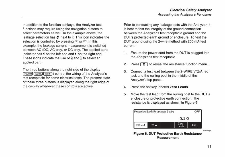
Prior to conducting any leakage tests with the Analyzer, it is best to test the integrity of the ground connection between the Analyzer’s test receptacle ground and the DUT’s protected earth ground or enclosure. To test the DUT ground using the 2-wire method with 200 mA test current:
1. Ensure the power cord from the DUT is plugged into the Analyzer’s test receptacle.
2. Press O to reveal the resistance function menu.
3. Connect a test lead between the 2-WIRE V/Ω/A red jack and the nulling post in the middle of the Analyzer’s top panel.
4. Press the softkey labeled Zero Leads.
5. Move the test lead from the nulling post to the DUT’s enclosure or protective earth connection. The resistance is displayed as shown in Figure 6.
faw06.eps
Figure 6. DUT Protective Earth Resistance Measurement
ESA620 Getting Started Manual
12
A low resistance reading is required to confirm a good ground connection through the power cord. Refer to the appropriate electrical safety standard for the specific limit value to be followed.
At this point, the Analyzer is ready to test the electrical safety of the DUT.
What to Do Next For more information on how to use the Analyzer, refer to the ESA620 Users Manual contained on the accompanying CD.
Maintenance The Analyzer needs little maintenance or special care. However, treat it as a calibrated measuring instrument. Avoid dropping or other mechanical abuse that could cause a shift in the calibrated settings.
Cleaning the Analyzer
XW Warning
To avoid electric shock, do not clean the Analyzer plugged into mains or attached to a DUT.
W Caution
Do not pour fluid onto the Analyzer surface; fluid seepage into the electrical circuitry may cause the Analyzer to fail.
W Caution
Do not use spray cleaners on the Analyzer; such action may force cleaning fluid into the Analyzer and damage electronic components.
Clean the Analyzer occasionally utilizing a damp cloth and mild detergent. Take care to prevent the entrance of liquids.
Wipe down the adapter cables with the same care. Inspect them for damage to and deterioration of the insulation. Check the connections for integrity before each use.

Electrical Safety Analyzer Replaceable Parts
13
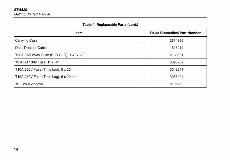
Replaceable Parts Table 4 list the parts and part numbers of the replaceable parts.
Table 4. Replaceable Parts
Item Fluke Biomedical Part Number
ESA620 Getting Started Manual 2814971
ESA620 Users Manual CD 2814967
USA 2238680
UK 2238596
Australia 2238603
Europe 2238615
France/Belgium 2238615
Italy 2238615
Power Cord
Israel 2434122
Ansur Plug-in, CD with demo version 2795488
USA, Australia, & Israel 650887 Test Probe Set
Europe 1541649
ESA620 Getting Started Manual
14
Table 4. Replaceable Parts (cont.)
Item Fluke Biomedical Part Number
Carrying Case 2814980
Data Transfer Cable 1626219
T20A 3AB 250V Fuse (SLO-BLO), 1¼″ x ¼″ 2183691
13 A BS 1362 Fuse, 1″ x ¼″ 3095769
T10A 250V Fuse (Time Lag), 5 x 20 mm 3046641
T16A 250V Fuse (Time Lag), 5 x 20 mm 3056494
15 – 20 A Adapter 2195732

Electrical Safety Analyzer Accessories
15
Accessories Table 5 lists available accessories for the Analyzer.
Table 5. Accessories
Item Fluke Biomedical Part Number
Test Leads with retractable sheath 1903307
Kelvin Test Lead Set for 4-wire ground 2067864
Ground Pin Adapters 2242165
ESA620 USA/AUS/ISR Accessory Kit: Test Lead Set TP1 Test Probe Set AC285 Alligator Clip Set
3111008
ESA620 EUR Accessory Kit: Test Lead Set TP74 Test Probe Set AC285 Alligator Clip Set
3111024
ESA620 Getting Started Manual
16
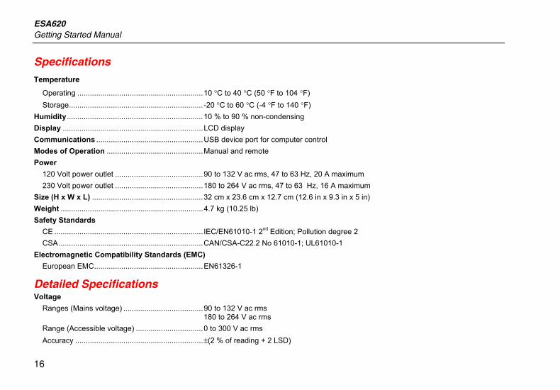
Specifications Temperature
Operating ............................................................10 °C to 40 °C (50 °F to 104 °F) Storage................................................................ -20 °C to 60 °C (-4 °F to 140 °F)
Humidity.................................................................10 % to 90 % non-condensing Display ...................................................................LCD display Communications ...................................................USB device port for computer control Modes of Operation ..............................................Manual and remote Power
120 Volt power outlet ..........................................90 to 132 V ac rms, 47 to 63 Hz, 20 A maximum 230 Volt power outlet ..........................................180 to 264 V ac rms, 47 to 63 Hz, 16 A maximum
Size (H x W x L) .....................................................32 cm x 23.6 cm x 12.7 cm (12.6 in x 9.3 in x 5 in) Weight ....................................................................4.7 kg (10.25 lb) Safety Standards
CE ....................................................................... IEC/EN61010-1 2nd Edition; Pollution degree 2 CSA.....................................................................CAN/CSA-C22.2 No 61010-1; UL61010-1
Electromagnetic Compatibility Standards (EMC) European EMC....................................................EN61326-1
Detailed Specifications Voltage
Ranges (Mains voltage) ......................................90 to 132 V ac rms 180 to 264 V ac rms
Range (Accessible voltage) ................................0 to 300 V ac rms Accuracy .............................................................±(2 % of reading + 2 LSD)
Electrical Safety Analyzer Detailed Specifications
17
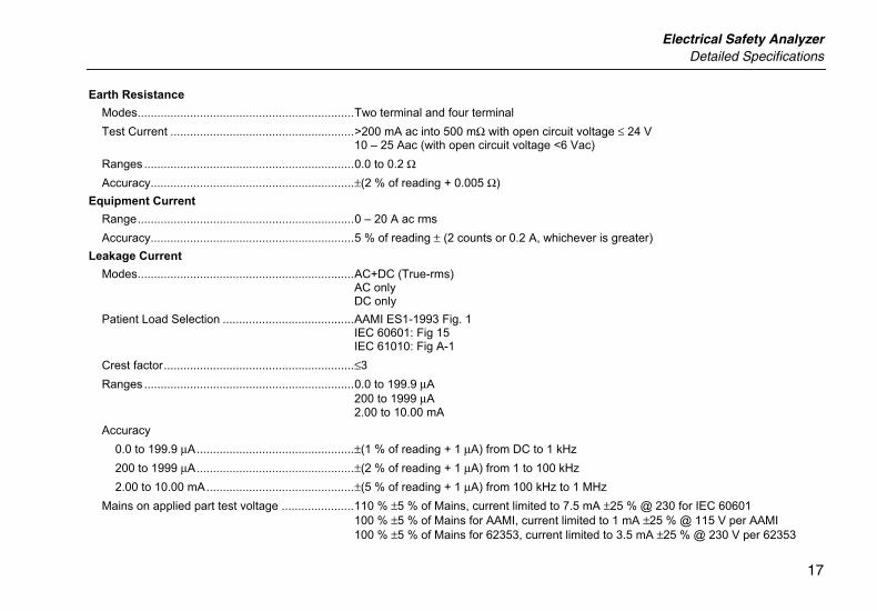
Earth Resistance Modes..................................................................Two terminal and four terminal Test Current ........................................................>200 mA ac into 500 mΩ with open circuit voltage ≤ 24 V
10 – 25 Aac (with open circuit voltage <6 Vac) Ranges ................................................................0.0 to 0.2 Ω Accuracy..............................................................±(2 % of reading + 0.005 Ω)
Equipment Current Range..................................................................0 – 20 A ac rms Accuracy..............................................................5 % of reading ± (2 counts or 0.2 A, whichever is greater)
Leakage Current Modes..................................................................AC+DC (True-rms)
AC only DC only
Patient Load Selection ........................................AAMI ES1-1993 Fig. 1 IEC 60601: Fig 15 IEC 61010: Fig A-1
Crest factor..........................................................≤3 Ranges ................................................................0.0 to 199.9 μA
200 to 1999 μA 2.00 to 10.00 mA
Accuracy 0.0 to 199.9 μA................................................±(1 % of reading + 1 μA) from DC to 1 kHz 200 to 1999 μA................................................±(2 % of reading + 1 μA) from 1 to 100 kHz 2.00 to 10.00 mA.............................................±(5 % of reading + 1 μA) from 100 kHz to 1 MHz
Mains on applied part test voltage ......................110 % ±5 % of Mains, current limited to 7.5 mA ±25 % @ 230 for IEC 60601 100 % ±5 % of Mains for AAMI, current limited to 1 mA ±25 % @ 115 V per AAMI 100 % ±5 % of Mains for 62353, current limited to 3.5 mA ±25 % @ 230 V per 62353
ESA620 Getting Started Manual
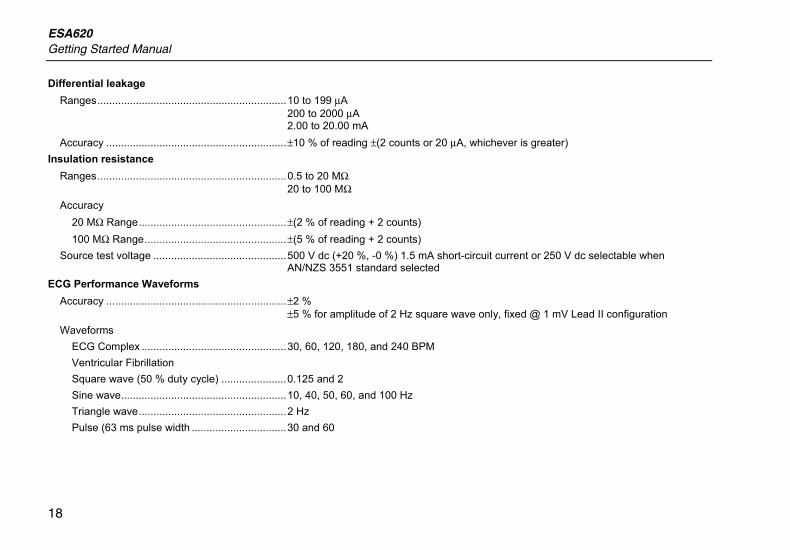
18
Differential leakage Ranges................................................................10 to 199 μA
200 to 2000 μA 2.00 to 20.00 mA
Accuracy .............................................................±10 % of reading ±(2 counts or 20 μA, whichever is greater) Insulation resistance
Ranges................................................................0.5 to 20 MΩ 20 to 100 MΩ
Accuracy 20 MΩ Range..................................................±(2 % of reading + 2 counts) 100 MΩ Range................................................±(5 % of reading + 2 counts)
Source test voltage .............................................500 V dc (+20 %, -0 %) 1.5 mA short-circuit current or 250 V dc selectable when AN/NZS 3551 standard selected
ECG Performance Waveforms Accuracy .............................................................±2 %
±5 % for amplitude of 2 Hz square wave only, fixed @ 1 mV Lead II configuration Waveforms
ECG Complex .................................................30, 60, 120, 180, and 240 BPM Ventricular Fibrillation Square wave (50 % duty cycle) ......................0.125 and 2 Sine wave........................................................10, 40, 50, 60, and 100 Hz Triangle wave..................................................2 Hz Pulse (63 ms pulse width ................................30 and 60
Related Documents
![Untitled-2 [] · Romance Pink Avadable in Ramco PRODUCTS . An Clin Angelina Available in 5 ml ... PANTHER PANTHER PANTHER PANTHER Black Panther Available in 100 Ramco](https://static.cupdf.com/doc/110x72/5b5319867f8b9a0d398b631e/untitled-2-romance-pink-avadable-in-ramco-products-an-clin-angelina-available.jpg)