Measurement Computing • 10 Commerce Way • Norton, MA 02766 • (508) 946-5100 • [email protected] • mccdaq.com 1 SAFETY CONCERNS In the United States, electrical potentials more than 48V are considered dangerous to human life. Although people have survived electrical shocks exceeding thousands of volts and lightning strikes carrying millions of joules of energy, everyone should treat electricity with caution and respect. Voltage is not the only concern, however. Currents in the mA range can stop a normal heart under certain conditions. For example, NIOSH (National Institute for Occupational Safety and Health) estimates that as little as 20 mA at 110 VAC, the common utility voltage, can paralyze respiratory muscles. All equipment and sources of voltage and current, such as the item under test, should not be powered when making connections between sensors, actuators or other components and the data acquisition system. This is especially critical when using current transformers and measuring high voltages and AC current. MAKING VALID MEASUREMENTS Accurate measurements depend on accurate equip- ment and robust connections. Poor connections and noise picked up through unshielded leads and improperly grounded circuits will certainly yield inac- curate data. Packaged sensors are typically designed to ensure accurate output signals with proper component placement, shielding, filtering, and bypassing power and ground I/O connections. Unprotected sensors, however, such as thermocouples and strain gages often are exposed to numerous types of noise signals that can couple into the sensors and leads and contaminate the desired signal. Those who install such sensors must follow industry-accepted practices to ensure that the sensors’ output signals are reliable, unbiased, and free of noise and interference. DC VOLTAGE Instrumentation Level DC Voltage Data acquisition systems usually contain integrated- circuit signal conditioners and multiplexers at their input terminals. These ICs typically can’t handle more than about ±10 VDC input, although some may tolerate as much as ±25 VDC. One way around the limitation is to place a voltage divider on the system’s input terminals that reduces the voltage to meet the IC’s specifications. Some systems are manually switched to the proper range, while others select the range automatically. In addition, after properly connecting the sensors, the item under test, and the data acquisition system, apply power first to the data acquisition system. Next energize the sensors and finally, the item under test. Some data acquisition systems can be damaged when voltages are applied to their inputs while unpowered. High DC Voltage Voltages greater than about 24 VDC are considered high voltage in data acquisition system terms. Built-in or external voltage dividers and special signal condition- ers are needed for dividing tens or hundreds of volts down to just 10V or less to protect the instrument’s input circuitry. One critical consideration for the safety of both the equipment and operators is to use high- voltage insulation in wires, terminals, connectors, leads, sensors, and other components to prevent leakage and arcing to low-potential terminals and nearby objects. Low DC Voltage Compared to high voltages, successfully measuring low-level DC signals depends upon appropriate wiring techniques between the signal source and the data acquisition device. Input amplifier stages in signal conditioning equipment cannot distinguish between the measured signal and a noise voltage coupled into lead wires. When measuring signals less than one volt, shielded or unshielded twisted pairs provide the best protection against noise voltage pickup. Best wiring practices call for shields to be grounded at one end only, preferably at the signal source. AC VOLTAGE Low AC Voltage General-purpose data acquisition systems often measure low-level AC voltages on the secondary of loaded cur- rent transformers, step-down potential transformers, clamp-on current probes, current-sensing resistors, or sensors lacking galvanic isolation. All these low-level AC voltages must have a low common-mode voltage component with respect to earth ground or float with minimal AC leakage. Also, connect the voltage source to earth ground when necessary. Electrical Measurements

Welcome message from author
This document is posted to help you gain knowledge. Please leave a comment to let me know what you think about it! Share it to your friends and learn new things together.
Transcript

Measurement Computing • 10 Commerce Way • Norton, MA 02766 • (508) 946-5100 • [email protected] • mccdaq.com
1
SAFETY CONCERNSIn the United States, electrical potentials more than 48V are considered dangerous to human life. Although people have survived electrical shocks exceeding thousands of volts and lightning strikes carrying millions of joules of energy, everyone should treat electricity with caution and respect. Voltage is not the only concern, however. Currents in the mA range can stop a normal heart under certain conditions. For example, NIOSH (National Institute for Occupational Safety and Health) estimates that as little as 20 mA at 110 VAC, the common utility voltage, can paralyze respiratory muscles.
All equipment and sources of voltage and current, such as the item under test, should not be powered when making connections between sensors, actuators or other components and the data acquisition system. This is especially critical when using current transformers and measuring high voltages and AC current.
MAKING VALID MEASUREMENTS Accurate measurements depend on accurate equip-ment and robust connections. Poor connections and noise picked up through unshielded leads and improperly grounded circuits will certainly yield inac-curate data. Packaged sensors are typically designed to ensure accurate output signals with proper component placement, shielding, filtering, and bypassing power and ground I/O connections. Unprotected sensors, however, such as thermocouples and strain gages often are exposed to numerous types of noise signals that can couple into the sensors and leads and contaminate the desired signal. Those who install such sensors must follow industry-accepted practices to ensure that the sensors’ output signals are reliable, unbiased, and free of noise and interference.
DC VOLTAGEInstrumentation Level DC VoltageData acquisition systems usually contain integrated-circuit signal conditioners and multiplexers at their input terminals. These ICs typically can’t handle more than about ±10 VDC input, although some may tolerate as much as ±25 VDC. One way around the limitation is to place a voltage divider on the system’s input terminals that reduces the voltage to meet the IC’s specifications.
Some systems are manually switched to the proper range, while others select the range automatically.
In addition, after properly connecting the sensors, the item under test, and the data acquisition system, apply power first to the data acquisition system. Next energize the sensors and finally, the item under test. Some data acquisition systems can be damaged when voltages are applied to their inputs while unpowered.
High DC VoltageVoltages greater than about 24 VDC are considered high voltage in data acquisition system terms. Built-in or external voltage dividers and special signal condition-ers are needed for dividing tens or hundreds of volts down to just 10V or less to protect the instrument’s input circuitry. One critical consideration for the safety of both the equipment and operators is to use high-voltage insulation in wires, terminals, connectors, leads, sensors, and other components to prevent leakage and arcing to low-potential terminals and nearby objects.
Low DC VoltageCompared to high voltages, successfully measuring low-level DC signals depends upon appropriate wiring techniques between the signal source and the data acquisition device. Input amplifier stages in signal conditioning equipment cannot distinguish between the measured signal and a noise voltage coupled into lead wires. When measuring signals less than one volt, shielded or unshielded twisted pairs provide the best protection against noise voltage pickup. Best wiring practices call for shields to be grounded at one end only, preferably at the signal source.
AC VOLTAGELow AC VoltageGeneral-purpose data acquisition systems often measure low-level AC voltages on the secondary of loaded cur-rent transformers, step-down potential transformers, clamp-on current probes, current-sensing resistors, or sensors lacking galvanic isolation. All these low-level AC voltages must have a low common-mode voltage component with respect to earth ground or float with minimal AC leakage. Also, connect the voltage source to earth ground when necessary.
Electrical Measurements

2
Measurement Computing • 10 Commerce Way • Norton, MA 02766 • (508) 946-5100 • [email protected] • mccdaq.com
Outlet Level AC VoltageIn the U.S. and Canada, utility wiring supports a nominal 110 VAC, 60 Hz, single-phase voltage, supplied with three wires; hot, neutral, and ground. Europe typically uses 220 VAC, 50 Hz, and Japan supplies 100 VAC; 50 Hz in Eastern Japan and 60 Hz in Western Japan. In many factories, 220/230 to 460/480 VAC, single and three-phase voltage, Wye and Delta configurations are also distributed to electrical and electronic control equipment. All these voltages are lethal and leads should be connected or disconnected from the data acquisition system and the equip-ment under test with the power disconnected.
When connecting these voltage sources to data acquisition systems, problems often crop up in ground loops, which produce noise. Voltage drops appear between the neutral wire and ground for many reasons, some of which cannot be eliminated easily or even found. Accepted practices for shielding, grounding, and isolation should be followed rigorously. Refer to Chapter 10 for more detailed information concerning ground loops and interference.
High VoltageSimilar to DC voltage levels, data acquisition system inputs typi-cally can’t handle more than ±10 VAC peak. Higher AC voltages are attenuated and scaled with a signal conditioning stage before they are processed. Voltages up to 2,000V, peak-to-peak, can be measured with a fully differential attenuator, calibrated to match the buffered differential inputs of a data acquisition system. At-tenuators are typically voltage divider networks connected from the high side input terminal to a common ground.
For systems with a true differential input, however, neither the input’s low nor high side can be connected directly to ground. Two matched resistor dividers attenuate the incoming signal, one on the high side and the other on the low side. Only the low side of the attenuator is grounded. For example, an accessory device is required to provide a 200:1 attenuation without affecting the amplifier’s high input impedance. In a typical system, the two matched buffer amplifiers, A and B (Figure 4.01), on the front end of the data acquisition system draw almost identical input bias current. Matched voltage dividers placed on the high and low-side inputs provide symmetrical current limiting from either input and let the quasi-differential input of the data acquisition
system measure a lower voltage referenced to analog common. Because the outputs from amplifiers A and B are identical, they can be considered a common-mode voltage that the differential amplifier C rejects.
This scheme attenuates the high and low signals, and lets both ends float hundreds of volts above ground. For example, the high input can be 110 VAC while the low end has a 50 VDC offset. After attenuation, the peak voltage of the high side signal is 0.77V and the low side signal is 0.25V, which are well within the read-able range of the data acquisition system’s differential inputs.
When a single-ended measurement is attempted by attenuating only the high signal and pulling the low signal to ground, two problems can develop. First, when the data acquisition system ground and the signal ground are different, tying them together forms a ground loop, which can result in excessive current and destroy the instrument or equipment. The second error component comes from the bias currents Ib flowing through the input pins of the two operational amplifiers, A and B shown in Figure 4.02. The bias current produces a voltage drop through the divider on the high side input, but the low side input has no matching drop. The difference appears at the input to differential amplifier C and produces an offset at its output.
Effective, Peak, Average, and RMS VoltageDc voltages and currents are relatively easy to measure and calculate with Ohm’s law. For example, DC power is mathemati-cally equivalent to the product of DC voltage and current and generates a unique amount of heat energy or performs a unique amount of work. By comparison, power calculations for AC volt-age and current includes an additional factor, the cosine of the phase angle between them, called the power factor. When the voltage and current waves are in phase, the cosine of the angle is unity, so the product of voltage and current is a valid power value measured in watts. When they are out of phase, however, the power factor is less than unity, so the power generated is less than the simple product of voltage and current. In an extreme case, 90˚ for example, the cosine of the phase angle is zero, so the wattage is also zero. However, the power is then totally reactive, does not generate heat (theoretically), and is simply labeled VA (volt-amperes).
C
A
B
5 MΩ≈50 kΩ
10 MΩ
5 MΩ≈50 kΩ
10 MΩ
High-voltage adapter Data acquisition system
Channel 1
Figure 4.01 (6.11)
Fig. 4.01. A typical data acquisition system usually requires an attenuator at its input to accept voltages that exceed 10 V.
High-Voltage Adapter
C
A
B
5 MΩ≈50 kΩ
10 MΩ
5 MΩ≈50 kΩ
10 MΩ
High-voltage adapter Data acquisition system
Channel 1
Figure 4.01 (6.11)
Fig. 4.02. A differential amplifier requires a resistor at both inputs when running single-ended, but only one resistor in a voltage-divider attenuator.
Differential Input Attenuation

3
Measurement Computing • 10 Commerce Way • Norton, MA 02766 • (508) 946-5100 • [email protected] • mccdaq.com
EQN 4.01. DC Power
P = E x I Where: E and I are in phaseP = power, WE = DC voltage, VI = DC current, A
EQN 4.02. AC Power
P = E x I x Cos φWhere: P = power, WE = AC voltage, VI = AC current, Aφ = phase angle between voltage and current
Effective VoltageThe AC voltage wave shape follows a sine function (ideally), and because it continually rises and falls over each cycle, the area under the curve for AC is less than for DC over the same (peak) amplitude and time period. Thus, 100 VAC peak generates less heat than 100 VDC in the same load. (See Figure 4.03.) To compensate for this, peak AC voltages must be higher than DC to generate an equivalent amount of heat. The value of AC voltage that produces an equivalent amount of work as the DC value is called the effective voltage and equals the DC value multiplied by 1.414. In other words, 141.4 peak VAC produces the same amount of heat in a given load, as does 100 VDC.
RMS VoltageIn order to make AC and DC voltmeter scales read the same value for the same amount of work done, the AC voltmeter scales are calibrated in rms (root mean square) voltage values. When ob-serving 100 VAC rms on the meter face, the voltage is actually 141.4 VAC peak, and the amount of work it does equals that of 100 VDC (in the same load). Moreover, for ac, the maximum (peak) positive excursion and the maximum negative excursions
are the same; therefore the peak-to-peak value in this example is twice 141.4 or 282.8 Vp-p.
The rms voltage value of a sine wave is equal to the effective value and is defined as the square root of the average of the squares of the instantaneous voltages measured over a given number of cycles.
EQN 4.03. Volts rms
Equation 4.03
Vrms = V12 + V2
2 + V32 + ...Vn
2
Figure 4.03
V
-V
t0
100
141.4
-100
-141.4
DC voltage
AC sine wave
90˚ 270˚ 450˚
(B)
(A)
(C) Peak (B)
Peak (A)
Ampl
itude
(v)
Effective voltage
Fig. 4.03. The numerical value for the peak voltage of AC must be 1.414 times that of DC to produce the same heating effect.
Effective Voltage
When the shape of the AC signal is not a near-perfect sine wave, ordinary vane-type voltmeters will not indicate a true rms AC value. Special meters and some data acquisition systems, however, are designed to compensate for the shape discrepancies and are called true rms meters. They measure and indicate the true rms value of the AC signal, regardless of the distortion. The average value of the AC voltage is zero, because the positive half cycle magnitude equals the negative half cycle of the wave shape.
CURRENTA Fundamental ProblemVoltage drops are relatively easy to measure with most instruments because the difference in voltage appears between any two points in a circuit. The circuit does not need to be disturbed or changed (provided the measuring instrument’s impedance is high com-pared with the impedance of the measured circuit) to make the measurement. By comparison, simple direct-connection current measurements are more troublesome, because the current appears within a loop and the loop must be opened to insert the ammeter.
Figure 4.04 Alternate
Vout
+15
–15
+
–
+
–
ALT
Alternator
50A50 mVshunt
Battery13.8V
commonmode
Fig. 4.04. The battery charging current in an automobile elec-trical system is typically measured with a handheld diagnostic voltmeter across a shunt resistor, which is totally isolated from the battery voltage. However, when a data acquisition input amplifier is connected to the shunt, the input also must sustain the common mode voltage represented by the battery.
Typical Data Acquisition Input

4
Measurement Computing • 10 Commerce Way • Norton, MA 02766 • (508) 946-5100 • [email protected] • mccdaq.com
Moreover, the ammeter contains a characteristic resistance or impedance that most often changes the circuit parameters and must be compensated to obtain accurate measurements.
Some current measuring instruments, however, can couple inductively and have little or no affect on the circuit parameters. Such probes are designed for both AC and DC circuits.
Insertion LossInserting an instrument or device in series with the circuit causes the total series impedance to change. In many applications, the added component or sensor requires some power to operate or drops some voltage resulting in what is called insertion loss. Therefore, some signal power may be consumed in making the measurement, which must be compensated to provide a more accurate measurement.
Common-Mode LimitationsMost differential amplifiers used for signal conditioners in data ac-quisition systems can sustain only a limited common mode voltage, typically about ±10 VDC. However, more expensive amplifiers or signal conditioners are available for special applications that sustain common mode voltages exceeding the 10 VDC limit.
One application, for example involves measuring the voltage drop across a calibrated shunt resistor in an alternator charging circuit. When the amplifier input is connected to the shunt resistor to measure mV scaled to charging current, the common mode voltage seen by the amplifier input is the maximum battery voltage, nominally 13.8 VDC, but may be as high as 18.5 VDC during high-current charging. Therefore, the common-mode voltage rating for the data acquisition system input must be greater than 18.5 VDC.
ShuntsData acquisition instruments usually measure high-level DC currents (in the ampere range) as a 50 or 100 mV voltage drop across
a calibrated shunt resistor. Figure 4.05 shows a special application for differential measurements where the three shunts have one end placed in the common side of a three-motor circuit. This arrangement provides a common ground that can be connected to an inexpensive monitoring unit with a non-isolated, low-voltage input. Unfortunately, not all circuits that need more than one shunt will have one end of each shunt conveniently connected to a common point. In these instances, more expensive, isolated analog input amplifiers are recommended.
Data acquisition systems also measure low-level DC currents with shunts. Many sensors output a standard 4 to 20 mA cur-rent, which is linearly related to the quantity being measured. The signal current passes through the shunt resistor, as shown in Figure 4.06, and the voltage drop across the shunt provides the input for the ADC.
Ohms law defines the nature of this simple circuit where the product of resistance (R) and current (I) yields the voltage: V = IR. Consequently, when the data acquisition system requires a 10V input for a 20 mA full-scale reading, a 500 W resistor does the job:
EQN. 4.04. Shunt Resistor
R = V/I = 10V/0.02A = 500 W
The current loop provides higher noise immunity and accuracy than does a voltage source when measuring with long leads of relatively high resistance. In this case, the lead resistance is part of the 500 W, so in a simple series circuit, the shunt resistor is often adjustable in order to calibrate the loop to exactly 20 mA full scale.
The accuracy and stability of the measured voltage across the shunt are only as accurate and stable as the shunt resistor itself. Resistor accuracies are commonly 5, 1, 0.5, 0.1 and 0.01% and come with a temperature coefficient that specifies their stability over a specific temperature range. In addition, a 0.1% resistor usually has a lower temperature coefficient and better long-term stability than a resistor with lower accuracy because of its construction, which is usually wire wound or metal film vs. carbon film or carbon composition.
Figure 4.05
CH2 L
AnalogCommon
Mux Board
CH2 HCH1 LCH1 HCH0 LCH0 H
MotorLoads
Supp
ly
Shunts
Good for a lowsignal reference
Bad for a lowsignal reference
Channels
Fig. 4.05. High DC currents are often measured with shunts using differential inputs sharing a common ground.
Ground Referenced Differential Measurement
Figure 4.06 (3.06)
100 kW
R +– ADC
i
A
Differential amplifierCurrentsource
Fig. 4.06. Sensors with 4 to 20 mA outputs are typically placed in series with a resistor to develop a voltage. The resistor is then connected to the input of a differential ampli-fier to measure the voltage drop.
Shunt Resistor Current Measurement

5
Measurement Computing • 10 Commerce Way • Norton, MA 02766 • (508) 946-5100 • [email protected] • mccdaq.com
Current TransformersHigh AC currents can be measured with shunts under special circumstances, but most often such direct connections to AC lines are extremely dangerous to humans. One way to get around the hazard is to use current transformers (CT) that isolate AC line voltages and reduce input current by a specified ratio. (See Figure 4.07.) A 500:5 CT, for example, has a 100:1 ratio and generates a secondary current of 5 A with 500 A in the primary. When a low value load resistor such as 0.01 W connects to the output of the current transformer, the full load secondary cur-rent produces 50 mVrms, which can be easily read with the data acquisition system’s analog input. Although this output voltage seems low, higher resistance values will drive the CT out of its calibrated range and reduce the accuracy of the measurement. Moreover, a CT rated at 2 VA can handle only a maximum us-able load resistance (including lead wires) of 0.08 W.
For safety, always make certain that the current loop is closed before applying power. An open-circuit CT can generate many thousands of volts at its terminals with lethal current levels. For example, consider a 5,000:5-A current transformer with a turns ration of 1,000 to 1, and 10 VAC output signal developed across a calibrated low impedance load. The open-circuit secondary voltage is then 1,000 X 10 = 10,000 VAC, a very dangerous level to be connect-ing or disconnecting to a data acquisition system shunt resistor.
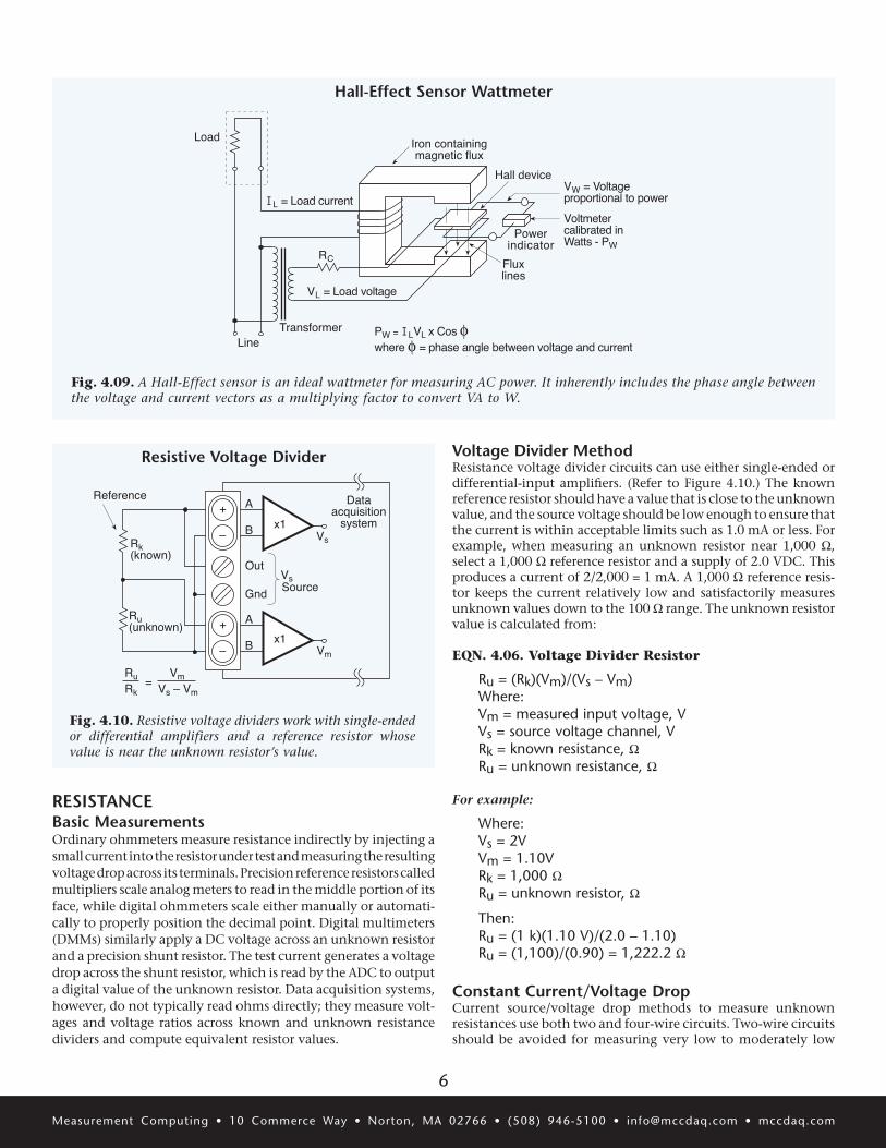
Hall-Effect SensorsIn 1879, Dr. Edwin Hall discovered the fundamental operating principle of the sensor named after him. The basic Hall-effect sensor operates under the influence of three parameters; current, voltage, and a magnetic field. Hall passed a constant current through a gold foil conductor while exposing the surface of the conductor to a magnetic field. A voltage drop developed across the opposite sides of the conductor with a magnitude dependent on the property of the sensor material (Hall coefficient) and proportional to the intensity of the magnetic field. (See Figure 4.08.)
A modern Hall device replaces the original conductor with a thin sheet of semiconductor material. The output voltage appears between two opposite edges of the sheet when the flat surface is
exposed to a magnetic field, and a calibrated current is injected across the other two opposite edges.
The Hall-effect sensor is ideal for measuring magnetic fields or AC and DC power. For power applications, it becomes a multiplying device. It automatically multiplies the voltage and current to yield power and includes the phase angle factor as an integral property. An electromagnetic coil generates the Beta field with its core perpendicular to the surface of the thin Hall element inside a shielded package. The coil connects in series with the load to sense load current, and the load voltage connects across the semiconductor element as shown in Figure 4.09. The result-ing current vector drives a readout device calibrated in watts or becomes a control signal to a power controller in a closed-loop circuit. Because the Hall-element material is temperature sensi-tive, a packaged Hall-effect wattmeter contains temperature-compensating circuits. The defining equation for the output is the product of the vectors:
EQN: 4.05. Hall-Effect Sensor Power
P = E x I x Cos (φ)Where: P = power in the load, WE = load voltage, VI = load current, Aφ = phase angle between load voltage and load current
A Hall-effect sensor intended to measure a magnetic field is con-structed such that the flat surface of the sensor element is exposed to the magnetic field. A calibrated voltage or current is applied to the edges of the semiconductor as described above, and the unit is calibrated to accurately measure a specific range of Beta (magnetic flux) values. The same principle is widely used in a Hall-effect switch, where the magnetic field bias may be applied with a permanent magnet and a slotted vane alternately interrupts the flux path. The output of the sensor switches between a low voltage and a high voltage as the flux path is interrupted. Such a device had been used as a switch for many years in numerous automobile distributors to replace the ignition points.
Figure 4.07 (6.17)
Vout = 50 mVrms0.01 W
I = 500 Arms
C.T.ratio
100:1
High-currentconductor
Fig. 4.07. Current transformers are a convenient means to measure high AC currents. The voltage dropped across the resistor is proportional to the current through the transformer.
Current Transformers
Figure 4.08 (4.09 A)
Currentsource
Flux linesSemiconductor
Voltmeter
Fig. 4.08. When either the voltage or current port is regu-lated and calibrated, the Hall-effect device can be used as a magnetic flux sensor. The unregulated port provides an output signal proportional to the magnitude of unknown flux density. However, a Hall-effect proximity sensor or switch is a more widely used component based on this principle.
Hall-Effect Sensor Flux Meter
6
Measurement Computing • 10 Commerce Way • Norton, MA 02766 • (508) 946-5100 • [email protected] • mccdaq.com
RESISTANCEBasic MeasurementsOrdinary ohmmeters measure resistance indirectly by injecting a small current into the resistor under test and measuring the resulting voltage drop across its terminals. Precision reference resistors called multipliers scale analog meters to read in the middle portion of its face, while digital ohmmeters scale either manually or automati-cally to properly position the decimal point. Digital multimeters (DMMs) similarly apply a DC voltage across an unknown resistor and a precision shunt resistor. The test current generates a voltage drop across the shunt resistor, which is read by the ADC to output a digital value of the unknown resistor. Data acquisition systems, however, do not typically read ohms directly; they measure volt-ages and voltage ratios across known and unknown resistance dividers and compute equivalent resistor values.
Figure 4.09A (4.08)
IL = Load current
Load
VL = Load voltage
RC
LineTransformer
Hall device
Iron containingmagnetic flux
Powerindicator
Fluxlines
VW = Voltageproportional to power
Voltmetercalibrated inWatts - PW
PW = ILVL x Cos φwhere φ = phase angle between voltage and current
Fig. 4.09. A Hall-Effect sensor is an ideal wattmeter for measuring AC power. It inherently includes the phase angle between the voltage and current vectors as a multiplying factor to convert VA to W.
Hall-Effect Sensor Wattmeter
Figure 4.10
B
–
+
–
+
B
A
A
Gnd
Out
Rk(known)
Ru(unknown)
x1
x1
Dataacquisition
systemVs
Vm
Source
Reference
RuRk
VmVs – Vm
=
Vs
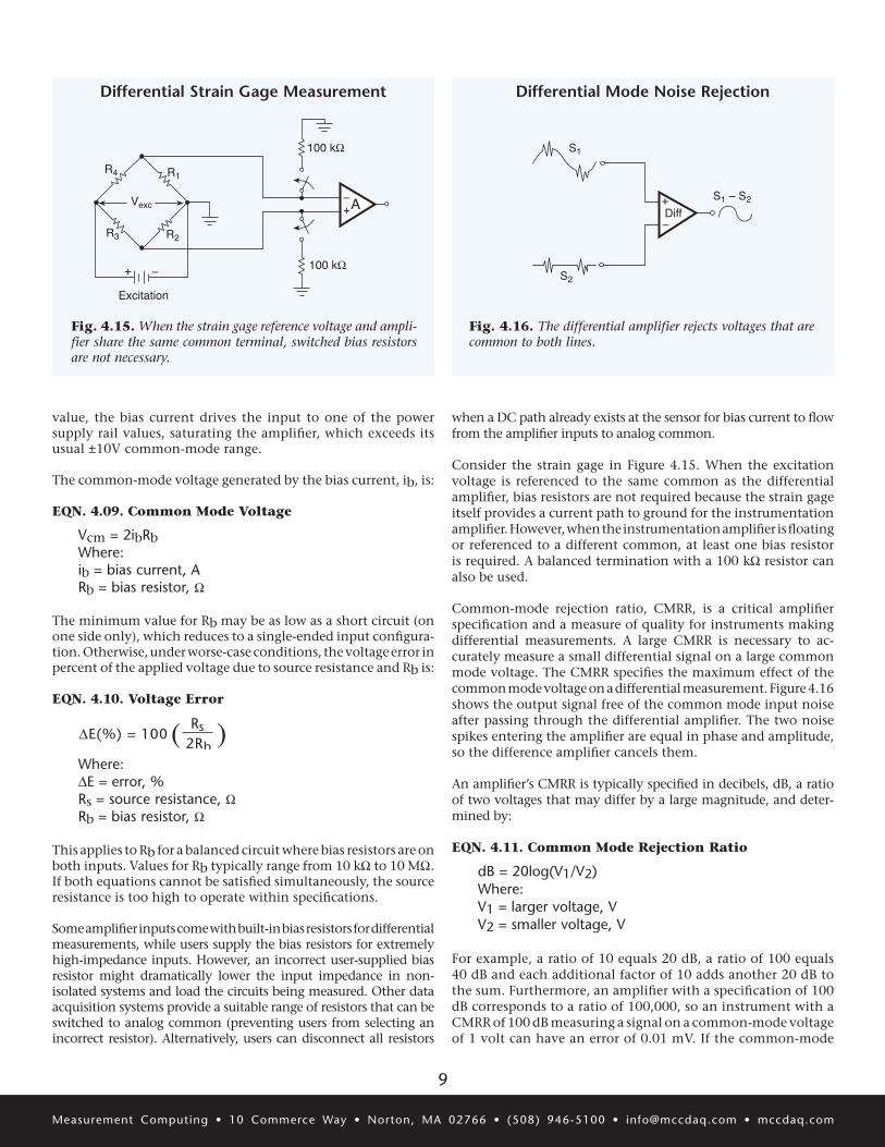
Fig. 4.10. Resistive voltage dividers work with single-ended or differential amplifiers and a reference resistor whose value is near the unknown resistor’s value.
Resistive Voltage Divider Voltage Divider MethodResistance voltage divider circuits can use either single-ended or differential-input amplifiers. (Refer to Figure 4.10.) The known reference resistor should have a value that is close to the unknown value, and the source voltage should be low enough to ensure that the current is within acceptable limits such as 1.0 mA or less. For example, when measuring an unknown resistor near 1,000 W, select a 1,000 W reference resistor and a supply of 2.0 VDC. This produces a current of 2/2,000 = 1 mA. A 1,000 W reference resis-tor keeps the current relatively low and satisfactorily measures unknown values down to the 100 W range. The unknown resistor value is calculated from:
EQN. 4.06. Voltage Divider Resistor
Ru = (Rk)(Vm)/(Vs – Vm)Where:Vm = measured input voltage, VVs = source voltage channel, VRk = known resistance, WRu = unknown resistance, W
For example:
Where: Vs = 2VVm = 1.10VRk = 1,000 WRu = unknown resistor, W
Then:Ru = (1 k)(1.10 V)/(2.0 – 1.10)Ru = (1,100)/(0.90) = 1,222.2 W
Constant Current/Voltage DropCurrent source/voltage drop methods to measure unknown resistances use both two and four-wire circuits. Two-wire circuits should be avoided for measuring very low to moderately low

7
Measurement Computing • 10 Commerce Way • Norton, MA 02766 • (508) 946-5100 • [email protected] • mccdaq.com
resistances because the lead wires and connections can become part of the total resistance (which is added to the unknown value).
Small DeviationsResistance measurement errors come from a number of sources. The most common errors in low resistance circuits for simple constant current/voltage drop methods using two wires come from the lead wire resistance and connections added to the unknown resistance. Keeping the lead wires short and using four-wire circuits such as Kelvin connections can minimize these errors. Errors in high resistance measurements can come from the shunt resistance of insulation, such as in wiring and connector bodies. When using a current source and measuring the voltage drop, use high input impedance measuring devices, whether they are voltmeters or signal conditioner inputs. For extremely high resistor measurements, use a voltage source and measure the current using short lead wires and robust connections.
WHEATSTONE BRIDGEBasic PrincipleWheatstone bridges often measure precise resistances and extremely small resistance changes. A typical bridge circuit is arranged in a symmetrical pattern of equal-value series-parallel resistors across a power source as shown in Figure 4.11. When all resistors are identical, the voltage drops across them are equal, and the voltage between nodes A and B is zero. When one or more resistors are not equal, which is usually the resistor under test, the bridge unbalances and a null meter placed between the nodes measures the amount of unbalance. An adjustable resistor or a potentiometer can be placed in one arm of the bridge to manually rebalance the circuit. When the potentiometer drives the meter back to zero, its value then equals that of the unknown
resistor. The potentiometer comes with a precision, calibrated readout device that indicates its resistance, which is also the value of the unknown resistor.
Anderson Loop AlternativeThe basic Anderson loop is often compared to a passive bridge circuit, but it provides higher accuracy measurements with less excitation voltage. Furthermore, it contains an amplifier, which puts it in the class of an active device.
The basic Anderson loop is a series circuit composed of one sens-ing element in series with one reference element powered by a constant-current source. A dual-differential operational amplifier with high temperature stability and high CMRR, called a sub-tractor, delivers the output response from the sensing element. (Refer to Figure 4.12.) The advantage of this topology lies in its ability to ignore changes in lead wire resistance and to amplify only the output changes of the sensing element.
The output response Vout of a basic strain-gage circuit is defined by:
EQN. 4.07. Anderson Loop Output
Vout = A1V1 – A2V2Vout = Ir (∆Rg)Where: A1 = amplification factor of stage 1A2 = amplification factor of stage 2V1 = voltage across sensing strain gage, VV2 = voltage across reference strain gage, VIr = constant current, A∆Rg = strain gage resistance change, W
Figure 4.11
–
+
Rw
Rxunknownresistor
Rw
Excitation
Nullmeter
Rw
BA
Vout
1.010
Rw
Precision resistordecade box
Precision calibrateddial or digital readout
Fig. 4.11. An unknown resistor placed in one arm of a Wheatstone bridge typically unbalances the circuit symmetry and produces an offset voltage across nodes A and B. But adjusting a precision, variable resistor in the opposite arm brings the circuit back into balance when it equals the unknown resistor value, which may be read on a calibrated dial.
Wheatstone Bridge
Figure 4.12
Rw1
R
Current loop
∆R
Rw2
Rw3
Rw4
RF V2
V1 A1
A2
VREF
Vg
Vout
SubtractorCurrentsource
Gage
A3
+
–
Fig. 4.12. The Anderson loop uses a unique subtractor cir-cuit, which eliminates errors arising from lead wire resistance. It measures only the sensing element’s resistance change.
Anderson Loop

8
Measurement Computing • 10 Commerce Way • Norton, MA 02766 • (508) 946-5100 • [email protected] • mccdaq.com
The circuit is not limited to only one sensor; it can be expanded to contain numerous sensors in series such as a strain rosette. It may be connected to signal conditioners with only six wires plus a common as illustrated in Figure 4.13. Additional advantages include an output voltage that is linear for each gage response, it requires only 1/4 the power needed by the conventional bridge circuit, and the loop output voltage is twice that of a conventional strain gage. The fact that the output signal of the Anderson loop is twice that of a strain gage Wheatstone bridge circuit accounts for a 6 dB increase in signal-to-noise ratio.
The output responses of a multiple strain gage arrangement can be expressed as:
EQN 4.08. Multiple Strain Gage Output
V1out – Vref = I∆R1V2out – Vref = I∆R2V3out – Vref = I∆R3V4out – Vref = I∆R4Where: Rref = Rn, nominal gage resistanceVnout = output voltage, VI = constant current, A∆Rn = the change in resistance of the nth strain gage, WVref = reference voltage, V
The significance of the output signal voltage, I∆Rn, is that it is principally a function of the change in resistance or impedance of the sensing element, not it’s absolute terminal resistance.
SINGLE-ENDED AND DIFFERENTIAL MEASUREMENTSBasic PrinciplesData acquisition systems provide for both single-ended and differential-input connections. The basic difference between the two is the choice of the common connection for analog voltage inputs. Single-ended multi-channel measurements require that all voltages be referenced to the same, well-chosen common node to prevent certain types of measurement errors. Sometimes, however, an ideal common point cannot be secured and a differential input is needed.
Differential connections cancel or ignore common-mode voltages and can measure the difference between the two connected points. The rejected common mode voltages can be steady DC levels or noise spikes. When given a choice, the differential input is preferred.
When to Make Single-Ended MeasurementsWhen single-ended and differential input measurements are offered in the same data acquisition system, the differential inputs usually consume two of the single-ended inputs. That is, 16 single-ended input amplifier channels equal 8 differential-input amplifier channels. When noise susceptibility and ground loops are not a concern, single-ended input measurements may be satisfactory.
When to Make Differential MeasurementsDifferential measurements call for a differential amplifier to measure the difference voltage between the two input sig-nal leads. Differential amplifiers are preferred because they provide greater noise rejection than single-ended amplifiers. Furthermore, some sensors, particularly strain gages, require measuring the voltage difference between the two signal leads. Figure 4.14 depicts a differential amplifier configured for a thermocouple. Although the amplifier measures the voltage difference between the two inputs, a path to ground is required on at least one input of the amplifiers. The 10 kW resistor between the low side and ground provides a path for amplifier bias current. If the resistor is absent or too high in
Figure 4.13
Current loop
+
–
+
–
+
–
+
–
GageR1 + ∆R1
+
–V1
GageR2 + ∆R2
+
–V2
GageR3 + ∆R3
+
–V3
GageR4 + ∆R4
+
–V4
+
–
Andersonsubtractors
Instrumentationamplifiers
VrefReference
input
Vref
Analogcommon
i,electricalcurrentsource
V1out
V2out
V3out
V4out
Rrefreference
impedance
Fig. 4.13. The Anderson loop may be connected to mul-tiple sensors in series such as in this strain rosette.
Anderson Loop for Multiple strain Gages
Figure 4.14
Thermocouple
Rb = 10 kW
Differentialamplifier
A
ib
Fig. 4.14. The resistor is necessary for at least one input to provide the path to ground for amplifier bias currents.
Differential Thermocouple Measurement
9
Measurement Computing • 10 Commerce Way • Norton, MA 02766 • (508) 946-5100 • [email protected] • mccdaq.com
value, the bias current drives the input to one of the power supply rail values, saturating the amplifier, which exceeds its usual ±10V common-mode range.
The common-mode voltage generated by the bias current, ib, is:
EQN. 4.09. Common Mode Voltage
Vcm = 2ibRbWhere: ib = bias current, ARb = bias resistor, W
The minimum value for Rb may be as low as a short circuit (on one side only), which reduces to a single-ended input configura-tion. Otherwise, under worse-case conditions, the voltage error in percent of the applied voltage due to source resistance and Rb is:
EQN. 4.10. Voltage Error
when a DC path already exists at the sensor for bias current to flow from the amplifier inputs to analog common.
Consider the strain gage in Figure 4.15. When the excitation voltage is referenced to the same common as the differential amplifier, bias resistors are not required because the strain gage itself provides a current path to ground for the instrumentation amplifier. However, when the instrumentation amplifier is floating or referenced to a different common, at least one bias resistor is required. A balanced termination with a 100 kW resistor can also be used.
Common-mode rejection ratio, CMRR, is a critical amplifier specification and a measure of quality for instruments making differential measurements. A large CMRR is necessary to ac-curately measure a small differential signal on a large common mode voltage. The CMRR specifies the maximum effect of the common mode voltage on a differential measurement. Figure 4.16 shows the output signal free of the common mode input noise after passing through the differential amplifier. The two noise spikes entering the amplifier are equal in phase and amplitude, so the difference amplifier cancels them.
An amplifier’s CMRR is typically specified in decibels, dB, a ratio of two voltages that may differ by a large magnitude, and deter-mined by:
EQN. 4.11. Common Mode Rejection Ratio
dB = 20log(V1/V2)Where: V1 = larger voltage, VV2 = smaller voltage, V
For example, a ratio of 10 equals 20 dB, a ratio of 100 equals 40 dB and each additional factor of 10 adds another 20 dB to the sum. Furthermore, an amplifier with a specification of 100 dB corresponds to a ratio of 100,000, so an instrument with a CMRR of 100 dB measuring a signal on a common-mode voltage of 1 volt can have an error of 0.01 mV. If the common-mode
( )
Figure 4.10
∆E(%) = 100Rs
2Rb
Figure 4.15
100 kW
100 kW
+–Vexc
Excitation
A
R1
R2R3
R4
+ –
Fig. 4.15. When the strain gage reference voltage and ampli-fier share the same common terminal, switched bias resistors are not necessary.
Differential Strain Gage Measurement
Figure 4.16
S1
S2
S1 – S2+
–Diff
Fig. 4.16. The differential amplifier rejects voltages that are common to both lines.
Differential Mode Noise Rejection
Where: ∆E = error, %Rs = source resistance, WRb = bias resistor, W
This applies to Rb for a balanced circuit where bias resistors are on both inputs. Values for Rb typically range from 10 kW to 10 MW. If both equations cannot be satisfied simultaneously, the source resistance is too high to operate within specifications.
Some amplifier inputs come with built-in bias resistors for differential measurements, while users supply the bias resistors for extremely high-impedance inputs. However, an incorrect user-supplied bias resistor might dramatically lower the input impedance in non-isolated systems and load the circuits being measured. Other data acquisition systems provide a suitable range of resistors that can be switched to analog common (preventing users from selecting an incorrect resistor). Alternatively, users can disconnect all resistors

10
Measurement Computing • 10 Commerce Way • Norton, MA 02766 • (508) 946-5100 • [email protected] • mccdaq.com
voltage is larger, or if greater accuracy is needed, an amplifier with a CMRR of at least 120 dB would be needed, a ratio of one million to one.
Calculate the CMRR for a differential amplifier given in a data sheet:
Where Adiff = differential gain = 10Acm = common mode gain = 0.001553
EQN. 4.12. Common Mode Rejection Ratio
CMRR = Adiff/Acm CMRR = 10/0.001553CMRR = 6,439
Find CMRR in dB:
EQN. 4.13. CMRR Example
CMRRdB = 20 log 6439 = 20(3.820) = 76.4 dB
High Common-Mode Voltage MeasurementsOften, a small voltage riding on a much larger voltage must be measured. For example, when a thermocouple sits on one terminal of a battery, the signal conditioner input must be able to measure the millivolt output of the thermocouple while sup-pressing the battery voltage. When the common-mode voltage is less than 15V, an instrument amplifier with differential inputs can read the thermocouple voltage while ignoring the battery voltage. When the common-mode voltage is higher than 15V, however, an isolation amplifier is usually required. (Also refer to Figure 4.04.)
Although isolation does not protect amplifiers against excessive normal-mode input voltage (voltage across a pair of inputs), it does protect against excessive common-mode voltage. Isolation eliminates a potentially large and damaging current that would flow from the signal source due to the common-mode voltage.
Several isolation methods inherently include high common-mode voltage rejection. Each channel can have an isolation amplifier, or a group of channels (not isolated from each other) can be multiplexed and digitized by an ADC before the digital data are isolated. Isolation barriers can be optical, magnetic, or capacitive. The most common types are optocouplers composed of infrared (IR) light-emitting diodes (LEDs) detected by photodiodes on the opposite side of a high-voltage, quartz barrier. Optocouplers can transmit numerical data in serial pulse trains or sine waves and pulse trains whose frequency or pulse width can be modulated with analog signals. Varying LED current, as shown in Fig. 4.17, can also transmit analog information. Magnetic barriers using transformers and capacitive barriers are generally internal and used in monolithic or hybrid isolation amplifiers.
In frequency-coupled isolation, a high-frequency carrier signal is inductively or capacitively coupled across the isolation barrier. The signal is modulated on the input side and demodulated on the output side to reproduce the original input signal.
Isolated ADCs and their accompanying signal conditioning circuits float. The ADC converts the input signal to a digital signal, and the interface for transferring the digital code is digitally isolated. (See Chapter 6.)
KELVIN CONNECTIONSBasic PrincipleWheatstone bridge circuits are accurate, simple, sensitive, and convenient ohmmeters to operate when the bridge, the unknown resistance, and the readout are all located near one another. But when the excitation and regulation circuit are located several meters away from the bridge circuit, the lead resistance, RL, may cause an error in the excitation voltage.
Figure 4.17 (2.07)
Photodiode LED
R
Inputground
Outputground
+–
+–Vinput
Voutput
LED
R
Photodiode
Fig. 4.17. When making high common-mode voltage mea-surements, optical couplers provide a convenient and safe means for connecting the voltage to data acquisition systems.
Optical Couplers
Figure 4.18
Excitation andregulation
A
+
–Vexc
+
–VsenseRL
RL
RL
R4
R3
R1
R2
RL
RL
RL
+–
Signalconditioning
Fig. 4.18. The Kelvin connection eliminates lead resistance from altering the excitation voltage by using a second pair of wires. The measuring device has relatively high input imped-ance so it does not draw current and develop a voltage drop across its leads that would add an error.
Kelvin Connection

11
Measurement Computing • 10 Commerce Way • Norton, MA 02766 • (508) 946-5100 • [email protected] • mccdaq.com
One way around the problem is to use a Kelvin connection, a method that connects the excitation and regulator circuits to the bridge with four wires. Two wires carry the excitation cur-rent, and the other two, the sense lines, measure the excitation voltage at the bridge and carry no current. Because the signal conditioning circuit has high input impedance, little current flows in the input leads, so their resistance does not introduce significant errors. (See Figure 4.18.)
Examples of Kelvin-Type MeasurementsAn example of the Kelvin circuit illustrates an ohmmeter com-posed of a current source and a voltmeter. (See Figure 4.19.) The voltmeter measures the voltage dropped by the load resistor so the value of the resistor is simply V/I. The accuracy of the calculated resistance in this configuration is directly proportional to the ac-curacy of the ammeter and voltmeter. The resistance is calculated with Ohms law:
EQN: 4.14. Kelvin Connection Resistance
Ru = V/IWhere: Ru = unknown resistance, WV = voltmeter reading, VI = ammeter reading, ARw = lead resistanceVs = voltage source
Although the load or unknown resistor may be located a consider-able distance from the ammeter and voltmeter, the long voltmeter leads in the Kelvin equivalent circuit do not drop significant voltage because they draw negligible current. Moreover, specially designed Kelvin clips are available that connect to the load with minimal voltage drop at the jaw hinges and contact surfaces.
Figure 4.19 A
+
–Ru
Rw
Rw
iV
Is
Rm
+
–
+
–
+
–
V ≈ Ω
Figure 4.19 B
+
–Ru V
Rw
Rw
IA
V ≈ Ω
Vs
+
–
Figure 4.19 C
+
–RuV
Rw
Rw
i ≈ 0
A
I
Rw
Rw
I
Vs
V ≈ Ω
Fig. 4.19. The basic ohmmeter circuit contains a current source and multiplier resistors so the voltmeter scale may be calibrated in W. The Kelvin connection uses more than one set of leads to eliminate the lead resistance as a variable in the equation for both local and remote measurements.
Common Ohmmeter Circuits
Basic Ohmmeter Circuit
Kelvin Connection for Remote Voltmeter
Kelvin Connection: Ohmmeter Circuit
Voltmeter calibrated in ohmsRm = Multiplier resistorsRw = Lead resistanceRu = Unknown resistorVs = Voltage sourceIs = Current source

12
Measurement Computing • 10 Commerce Way • Norton, MA 02766 • (508) 946-5100 • [email protected] • mccdaq.com
Data Acquisition Solutions
Low-cost muLtifunction moduLesUSB-1208, 1408, 1608 Series
AdVAnced meAsuRement PRoducts6000 Series
• Up to 8 analog inputs
• 12-, 14-, or 16-bit resolution
• Up to 200 kS/s sampling
• Digital I/O, counters/timers
• Up to 2 analog outputs
• Included software and drivers
• Measure strain, temperature, or voltage
• 12 channels
• Up to 24-bit resolution
• Up to 100 kS/s sampling per channel
• 8 digital I/O
• Encore software included with each module
HigH-AccuRAcY muLtifunctionUSB-2416 Series
• 24-bit resolution
• Measure thermocouples or voltage
• 32 single ended/16 differential inputs
• Up to 4 analog outputs, digital I/O, counters
• Expandable to 64 channels
• Included software and drivers
VoLtAge, temPeRAtuRe, And bRidge-bAsed inPut moduLesUSB-2404 Series
• 4 universal analog inputs
• Directly measure voltage, resistance, temperature, current, or bridge-based sensors
• 24-bit resolution
• Simultaneous sampling
• Up to 50 kS/s sampling
• Included software and drivers
Related Documents