International Journal of Engineering Materials and Manufacture (2016) 1(1) 3-10 Electrical Discharge Machining (EDM): A Review Asfana Banu and Mohammad Yeakub Ali Received: 16 July 2016 Accepted: 31 July 2016 Published: 05 September 2016 Publisher: Deer Hill Publications © 2016 The Author(s) Creative Commons: CC BY 4.0 ABSTRACT Electro discharge machining (EDM) process is a non-conventional and non-contact machining operation which is used in industry for high precision products. EDM is known for machining hard and brittle conductive materials since it can melt any electrically conductive material regardless of its hardness. The workpiece machined by EDM depends on thermal conductivity, electrical resistivity, and melting points of the materials. The tool and the workpiece are adequately both immersed in a dielectric medium, such as, kerosene, deionised water or any other suitable fluid. This paper provides an important review on different types of EDM operations. A brief discussion is also done on the machining responses and mathematical modelling. Keywords: WEDM, Micro-EDM, Non-conductive ceramics, dry EDM, dry WEDM, MRR, Kerf 1 INTRODUCTION Electro discharge machining (EDM) process is a non-conventional and non-contact machining operation which is used in industry for high precision products especially in manufacturing industries, aerospace and automotive industries, communication and biotechnology industries [1-7]. EDM as shown in Figure 1, is known for machining hard and brittle conductive materials since it can melt any electrically conductive material regardless of its hardness [4-5]. EDM is a type of thermal machining where the material from the workpiece is removed by the thermal energy created by the electrical spark [5, 8, 9]. The workpiece machined by EDM depends on thermal conductivity, electrical resistivity, and melting points of the materials [10-12]. A series of electrical sparks or discharges occur rapidly in a short span of time within a constant spark gap between micro sized tool electrode and workpiece material. The nature of sparks is repetitive and discrete. The tool and the workpiece are adequately both immersed in a dielectric medium, such as, kerosene, deionised water or any other suitable fluid [5, 13, 14]. The non-contact nature of the process with nearly force free machining allows a soft and easy to machine electrode materials to machine a very hard, fragile or thin workpieces [15-17]. Thus, due to its non-contact nature; mechanical stresses, chatter, and vibration problems during machining can be eliminated [18]. This paper is reviewed comprehensively on types of EDM operation. A brief discussion is also done on the machining responses and mathematical modelling. Figure 1: Schematic diagram of EDM. A. Banu and M. Y. Ali Department of Manufacturing and Materials Engineering International Islamic University Malaysia PO Box 10, 50728 Kuala Lumpur, Malaysia E-mail: [email protected] Reference: Banu, A. and Ali, M. Y. (2016). Electrical Discharge Machining: A Review. International Journal of Engineering Materials and Manufacture, 1(1), 3-10.

Welcome message from author
This document is posted to help you gain knowledge. Please leave a comment to let me know what you think about it! Share it to your friends and learn new things together.
Transcript

International Journal of Engineering Materials and Manufacture (2016) 1(1) 3-10
Electrical Discharge Machining (EDM): A Review Asfana Banu and Mohammad Yeakub Ali
Received: 16 July 2016 Accepted: 31 July 2016 Published: 05 September 2016 Publisher: Deer Hill Publications © 2016 The Author(s) Creative Commons: CC BY 4.0
ABSTRACT Electro discharge machining (EDM) process is a non-conventional and non-contact machining operation which is used in industry for high precision products. EDM is known for machining hard and brittle conductive materials since it can melt any electrically conductive material regardless of its hardness. The workpiece machined by EDM depends on thermal conductivity, electrical resistivity, and melting points of the materials. The tool and the workpiece are adequately both immersed in a dielectric medium, such as, kerosene, deionised water or any other suitable fluid. This paper provides an important review on different types of EDM operations. A brief discussion is also done on the machining responses and mathematical modelling. Keywords: WEDM, Micro-EDM, Non-conductive ceramics, dry EDM, dry WEDM, MRR, Kerf 1 INTRODUCTION Electro discharge machining (EDM) process is a non-conventional and non-contact machining operation which is used in industry for high precision products especially in manufacturing industries, aerospace and automotive industries, communication and biotechnology industries [1-7]. EDM as shown in Figure 1, is known for machining hard and brittle conductive materials since it can melt any electrically conductive material regardless of its hardness [4-5]. EDM is a type of thermal machining where the material from the workpiece is removed by the thermal energy created by the electrical spark [5, 8, 9]. The workpiece machined by EDM depends on thermal conductivity, electrical resistivity, and melting points of the materials [10-12]. A series of electrical sparks or discharges occur rapidly in a short span of time within a constant spark gap between micro sized tool electrode and workpiece material. The nature of sparks is repetitive and discrete. The tool and the workpiece are adequately both immersed in a dielectric medium, such as, kerosene, deionised water or any other suitable fluid [5, 13, 14]. The non-contact nature of the process with nearly force free machining allows a soft and easy to machine electrode materials to machine a very hard, fragile or thin workpieces [15-17]. Thus, due to its non-contact nature; mechanical stresses, chatter, and vibration problems during machining can be eliminated [18]. This paper is reviewed comprehensively on types of EDM operation. A brief discussion is also done on the machining responses and mathematical modelling.
Figure 1: Schematic diagram of EDM.
A. Banu and M. Y. Ali Department of Manufacturing and Materials Engineering International Islamic University Malaysia PO Box 10, 50728 Kuala Lumpur, Malaysia E-mail: [email protected] Reference: Banu, A. and Ali, M. Y. (2016). Electrical Discharge Machining: A Review. International Journal of Engineering Materials and Manufacture, 1(1), 3-10.

Electrical Discharge Machining: A Review
2 TYPES OF ELECTRO DISCHARGE MACHINING (EDM) Some of the variations of EDM process that can be altered for micro fabrication applications are micro-EDM, wire EDM (WEDM), dry EDM [4, 19-21]. 2.1 Wire EDM (WEDM) Wire electrical discharge machining (WEDM) was introduced because it has the ability to cut intricate shapes and extremely tapered geometries with high performance especially in precision, efficiency, and stability [5, 22, 23]. WEDM operation has a very similar material removal mechanism as EDM process except WEDM uses winding wire as an electrode [5, 6, 24]. Micro-WEDM operation uses a very small diameter wire (Ø 20-50 µm) as the electrode to cut a narrow width of cut in the workpiece. The wire is pulled through the workpiece from a supply spool onto a take-up mechanism. Discharge occurs between the wire electrode and the workpiece in the presence of a flood of dielectric fluid. The most important control parameters for this process are discharge current, discharge capacitance, pulse duration, pulse frequency, wire speed, wire tension, voltage, and dielectric flushing condition [6, 20, 25]. 2.2 Micro-EDM EDM operation has already been developed in micro scale industries, as delicate micro tools can machine workpiece surface without any deviation or breakage. Micro-EDM follows the similar principle of conventional EDM technology. However, there are some differences between these two machining in terms of circuitry. EDM uses resistance capacitance relaxation (RC-relaxation) circuit while micro-EDM uses RC-pulse circuit. In RC-relaxation circuit, current and voltage are usually assumed as constant in modelling process. However, in reality, for RC-relaxation circuit, current and voltage are controlled at a predefined level throughout the pulse on-time. In contrast, based on the modelling process and parametric analysis, RC-pulse generator for a single discharge shows that the current and voltage are not maintained to any predefined level. Still, the RC-pulse generator depends on capacitor charge state at any instant. The RC-pulse circuit type is known to have low material removal rate (MRR) since it can produce very small amount of discharge energy. Micro-EDM is particularly developed to manufacture component of sized between 1 and 999 µm. Hence, in order to produce high precision and high accuracy micro geometries products, micro-EDM is a suitable type of machining [26-29]. 2.3 EDM of Non-Conductive Materials Materials that are able to provide a minimum electrical conductivity of 0.1 Scm-1 can be processed using EDM. Thus, materials like metals and conductive ceramics are capable to undergo this process [30-32]. Researchers are applying EDM and micro-EDM to machine ceramics since they are difficult to machine using conventional cutting techniques [33, 34]. But, in order to make the machining process to be continuous, the ceramics need to be conductive. So, one of the solutions is to create a composite with dopants such as titanium nitride (TiN) or tungsten carbide (WC) onto the ceramic. Other alternative is to create a conductive compound by embedding the ceramic particles in a metal matrix. Another approach is by using the ultrasonic assisted spark erosion. The ultrasonic energy can assist in creating spark erosion and lead to crack formation that causes spalling [10, 31, 32]. Non-conductive ceramics also have been successfully machined by EDM using the assisting electrode method (AEM) (Figure 2) with some modifications done in the process which is one of the commonly method used [31, 32, 35-37]. In AEM, a conductive layer is applied on top of the non-conductive ceramic in order to generate spark between the workpiece and the tool electrode. High temperature around the dielectric fluid will degenerate the polymer chains and creates carbon elements from cracked polymer chains. The carbon elements, together with the conductive debris cover the ceramic surface to sustain the conductivity [10, 31, 32, 36, 38-40].
Figure 2: Schematic diagram of micro-EDM of non-conductive zirconia using adhesive copper assisting electrode [38].
4

Banu and Ali (2016): International Journal of Engineering Materials and Manufacture, 1(1), 3-10
2.4 Dry EDM In EDM process, dielectric fluid plays an important role in order to flush away the debris from the machining gap. In addition, the dielectric fluid also helps to improve the efficiency of the machining operation as well as improving the quality and economy of the machined parts. The commonly used dielectric fluids are mineral oil-based liquid or hydrocarbon oils which cause fire hazard and environmental problems. This is because dielectric wastes generated during the machining operation are very toxic and non-recyclable. Besides that, during the machining operation, toxic fumes (CO and CH4) are produced because of the high temperature chemical breakdown of mineral oils. The toxic fumes also pose a health hazard to the machining operators [24, 41-45]. In order to avoid these problems, researchers introduce dry EDM which includes dry WEDM, dry micro-EDM, and dry micro-WEDM [4, 5, 24, 46, 47].
Dry EDM (Figure 3) is a green machining method where the electrode used is in a pipe form and gas or air flows through the pipe instead of the liquid as a dielectric fluid which removes the debris from the gap and cools the machining surface [48-52]. As for dry WEDM, also known as the WEDM using dry dielectric fluid is a modification of the oil WEDM operation where gas is used as dielectric fluid instead of liquid. The flow of gas with high pressure helps to remove the debris and also avoids unnecessary heating of the wire and workpiece at the discharge gap. Lower tool wear, better surface quality, lower residual stresses, thinner white layer, and higher precision in machining are the prime outcome of this dry technique [1, 24, 53-56]. This dry technique can be applicable for almost all micro level machining operation [52, 57].
Figure 3: Schematic diagram of dry EDM.
There are researchers who do not agreed with the idea of using the gas instead of the liquid as the dielectric fluid. It is because when the sparks happened in the air, the erosion effect would be very small since the electrical discharge loses its energy. Moreover, the bubble of vapour expands which resulted from the spark into the dielectric fluid and causes the dynamic plasma pressure to rise. It is due to the surrounding dielectric fluid restricts the plasma growth. The bubble collapses and removes the molten metal out of the crater when the temperature decreases during the off time. Even though there are some disagreements among the researchers, the dry EDM was first introduced and reported by NASA in 1985 [58]. The commonly used gases as the dielectric fluid are atmospheric air, compressed air, liquid nitrogen, oxygen, argon and helium gas [51, 56, 59]. Some research shows that material removal rate (MRR) improves when oxygen is used as the dielectric fluid [60, 61]. It is because the oxidation reaction occurs with the supply of the oxygen gas which increases the work removal volume during one discharge cycle. In addition, there is no corrosion on the machining surface but it may suffer from rusting due to the oxidation [61].
Compared to conventional WEDM, the vibration of the wire electrode, narrower gap distance, and very negligible process reaction force in dry micro-WEDM assists this process to enable high accuracy in finishing of cut. Higher machining speed and lower electrode wear ratio are achieved in dry EDM milling. Three dimensional (3D) machining of cemented carbide can be done by using dry EDM milling [53, 62]. Higher material removal rate (MRR) can also be achieved in dry EDM when the workpiece is added with the ultrasonic vibration. This is because the ultrasonic vibration helps to flush of the molten metal from the craters [19]. Polarity is a one of the important factor in machining dry EDM. When the polarity of the tool electrode is negative, the tool wear ratio is smaller and the material removal rate is higher compared to the positive polarity [1, 56]. The machining operation stability is maintained when the tool is in rotation or planetary motion [63]. Low electrode wear ratio in dry EDM is due to the small physical damage of the tool electrode caused by the reactive force. It is because the dry EDM is free from the vaporization of liquid dielectric fluid when the discharge occurs. Besides that, adhesion of machining debris on the electrode helps to reduce electrode wear [61].
5

Electrical Discharge Machining: A Review
3 MACHINING RESPONSES 3.1 Kerf Kerf (Figure 4) is a width of the machined slots which is one of the most vital characteristics of WEDM [64, 65]. The corner errors and kerf variation are usually caused by the wire tool deflection and vibration in the discharge gap. These are the main factors that affect the WEDM machining accuracy. However, the kerf variations have higher influences on dimensional accuracy in micro-WEDM compared to the conventional WEDM. This is because, the relative error found in miniature parts produce by the micro-WEDM are bigger than the corresponding values in conventional WEDM [20]. Besides that, a stable machining performance in micro-WEDM is related to the debris free machined kerf. It is evident from the debris tracking analysis that the most debris are left out from the kerf section under any constant fluid flow rate. More effectively debris can be excluded and high micro-WEDM performance is obtainable with the improvement of jet flushing conditions of the working fluid from the nozzles [66].
In another study, the spark locations using the recorded images, and the effects of servo voltage, pulse interval time, and wire running speed on the distribution of spark location were investigated. The spark distribution is found uniform when servo voltage is high, pulse interval time is long, and wire running speed is low when experimental results are clarified [67]. Based on the research, the kerf on germanium wafers in micro-WEDM process was analysed using different thin wires with various voltage and capacitor settings. Up to 57% more wafers can be sliced in micro-WEDM which depends on wafer thickness and the thin wires. The wafer slicing with WEDM is suggested for mainly expensive semiconductor materials [68]. A model on lateral vibration of wire is established where co-related micro-WEDM parameters and vibration amplitude of the wire are analysed. The wire vibration is affected by the open voltage which also measures the breakdown distance. Kerf width can be controlled and subsequently machining precision can be improved by controlling the parameter [20].
Figure 4: SEM micrograph of kerf produced by micro-WEDM with 70 µm diameter tungsten wire electrode. 3.2 Material Removal Rate (MRR) Dimensional accuracy becomes vital when it comes to EDM since close tolerance components are required for products like tools, dies, and mold for press works, plastic molding, and die casting. Thus, MRR has been one of the main concerns. The MRR is expressed as the weight of material removed from workpiece over a period of machining time. Many researchers have attempted to develop empirical models to estimate MRR. The MRR depends on the amount of pulsed current in each discharge, frequency of the discharge, electrode material, work material, polarity, and dielectric flushing condition. [12, 69, 70]. MRR is low when electrode is connected to negative polarity or cathode. This is due to the dissociated carbon element in dielectric fluid tends to remain to anode and formed the recast layer [41].
Material removal mechanism in micro-EDM is debatable according to some of the researcher. This is because they are certain deviations in fundamental process mechanism. Even though they are many uncertainties regarding the mechanism of the material removal in micro-EDM, this machining process is still widely being used in industry for high-precision machining for conductive materials. Micro-EDM has the capability in removing the material in sub-grain size range (0.1-10 µm) regardless of their hardness [51]. 4 MATHEMATICAL MODELLING There are quite a numbers of studies are found on parametric study and development of empirical model on micro-WEDM parameters. Gap voltage, capacitance, and feed rate were considered as the control parameters and material removal rate (MRR), over cut, kerf, and surface roughness as the performance measures. The optimal parametric settings were derived using simulation. Some of the modelling are done through central composite design (CCD), response surface method (RSM), neural network method, regression analysis, neural network with back-propagation,
kerf
6
Banu and Ali (2016): International Journal of Engineering Materials and Manufacture, 1(1), 3-10
neuro-fuzzy inference system (ANFIS), grey relational analysis, and Taguchi L18 orthogonal array method [20, 24, 64, 71, 72]. Modelling is a strong tool for the integration of relationships between output performance and controllable input parameters. There are a few examples of mathematical modelling shown in this review. Eqn (1) is an example of mathematical model for vibration in micro end milling using Taguchi as the design while the analysis is done by the ANOVA [73]. As for Eqn (2) and (3), shows the mathematical model of hardness and MRR of non-conductive zirconia using micro-EDM [38]. V = 65.94 + 2.13 × 10⁻³n − 0.99f + 1.73 × 10⁻³d − 6.84 × 10⁻⁵nf − 1.93 × 10⁻³nd + 1.01fd (1) Where; V is average vibration, n is spindle speed (rpm), f is feed rate (mm/min), d is depth of cut (µm). H = 9201.15− 62n + 16v + 0.15n2 − 0.05nv − 1x10⁻⁴n3 (2) Where, H = hardness (Hv), n = rotational speed (rpm), v = gap voltage (V). MRR = −101.7 + 1.9n − 2.93v − 4.36 × 10⁻³n2 + 0.012v2 + 1.1 × 10⁻³nv + 3.1 × 10⁻⁶n3 (3) Where; MRR = material removal rate (µg/min), n = rotational speed (rpm), v = gap voltage (V). 5 SUMMARY EDM process is a flexible machining operation which has the capability in producing complex three dimensional (3D) shapes especially in manufacturing industries, aerospace and automotive industries, communication and biotechnology industries. It is known for machining hard and brittle conductive materials. The tool and the workpiece are adequately both immersed in a dielectric medium. This paper provides an important review on different types of EDM operations. A brief discussion is also done on the machining responses and mathematical modelling. This reviewed paper summarizes that:
1. WEDM has the ability to cut intricate shapes and extremely tapered geometries with high performance. 2. Micro-EDM is developed to manufacture micro geometries component with high precision and high
accuracy. 3. Non-conductive ceramics machined by EDM using assisting electrode method (AEM) which leads to new
structuring of advanced ceramic without geometry diversity. 4. Dry EDM is a process where gas is used as the dielectric fluid instead of the liquid. It is a process where
certain modification during the machining operation is needed in order to achieve a stable machining process.
5. Machining responses such as kerf and MRR are important in order to achieve maximum material removal with high accuracy and precision components.
ACKNOWLEDGEMENT This research was funded by Ministry of Science, Technology and Innovation, Malaysia under Research Grant SF15-016-0066. The authors are grateful to those who contributed directly and indirectly in producing this paper. REFERENCES 1. Abbas, M. N., Solomon, D. G., & Fuad Bahari, M. (2007). A review on current research trends in electrical
discharge machining (EDM). International Journal of Machine Tools and Manufacture, 47(7), 1214-1228. 2. Liao, Y. S., Chen, S. T., & Lin, C. S. (2005). Development of a high precision tabletop versatile CNC wire-EDM
for making intricate micro parts. Journal of Micromechanics and Microengineering, 15, 245-253 3. Yoo, H. K., Kwon, W. T., & Kang, S. (2014). Development of a new electrode for micro-electrical discharge
machining (EDM) using Ti(C,N)-based cermet. International Journal of Precion Engineering and Manufacturing, 15 (4), 609-616.
4. Hoang, K. T. & Yang, S. H. (2013). A study on the effect of different vibration-assisted methods in micro-WEDM. Journal of Materials Processing Technology, 213, 1616-1622.
5. Hoang, K. T. & Yang, S. H. (2015). A new approach for micro-WEDM control based on real-time estimation of material removal rate. International Journal of Precision Engineering and Manufacturing, 16 (2), 241-246.
6. Debroy, A. & Chakraborty, S. (2013). Non-conventional optimization techniques in optimizing non-traditional machining processes: a review. Management Science Letters, 3(1), 23-38.
7. Yan, M. T. (2010). An adaptive control system with self-organizing fuzzy sliding mode control strategy for micro wire-EDM machines. International Journal of Advanced Manufacturing Technology, 50, 315-328.
8. Pour, G. T., Pour, Y. T., & Ghoreishi, M. (2014). Electro-spark nanomachining process simulation. International Journal of Materials, Mechanics and Manufacturing, 2 (1).
9. Pour, G. T., Pour, Y. T., & Ghoreishi, M. (2014a). Thermal model of the electro-spark nanomachining process. International Journal of Materials, Mechanics and Manufacturing, 2 (1), 56-59.
7

Electrical Discharge Machining: A Review
10. Mohri, N., Fukuzawa, Y., Tani. T., Saito, N., & Furutani, K. (1996). Assisting electrode method for machining insulating ceramics. Annals of the CIRP, 45, 201-204.
11. Mohri, N., Fukusima, Y., Fukuzawa, Y., Tani, T., & Sato, N. (2003). Layer generation process on work-piece in electrical discharge machining. CIRP Annals – Manufacturing Technology, 52 (1), 157-160. DOI:10.1016/S0007-8506(07)60554-X.
12. Mahardika, M., Tsujimoto, T., & Mitsui, K. (2008). A new approach on the determination of ease of machining by EDM processes. International Journal of Machine Tools and Manufacture, 48, 746-760. DOI:10.1016/j.ijmachtools.2007.12.012.
13. Chow, H. M., Yang, L. D., Lin, C. T., & Chen,Y. F. (2008). The use of SiC powder in water as dielectric for micro-slit EDM machining. Journal of Materials Processing Technology, 195 (1-3), 160–170.
14. Chen, Y. F., Lin, Y. C., Chen, S. L., & Hsu, L. R. (2009). Optimization of electrodischarge machining parameters on ZrO2 ceramic using the Taguchi method. Proceeding of the Institution of Mechanical Engineers, Part B: Journal of Engineering Manufacture, 224, 195-205.
15. Jahan, M. P., Wong, Y. S., & Rahman, M. (2009). A study on the quality micro-hole machining of tungsten carbide by micro-EDM process using transistor and RC-type pulse generator. Journal of Materials Processing Technology, 209, 1706-1716. DOI:10.1016/j.jmatprotec.2008.04.029.
16. Masuzawa, T. (2000). State of the art of micromachining. CIRP Annals – Manufacturing Technology, 49 (2), 473-488. DOI:10.1016/S0007-8506(07)63451-9.
17. Schubert, A., Zeidler, H., Hackert, M., Schneider, J., & Hahn, M. (2013). Enhancing micro-EDM using ultrasonic vibration and approaches for machining of nonconducting ceramics. Journal of Mechanical Engneering, 59 (3), 156-164. DOI:10.5545/sv-jme.2012.442.
18. Ho, K. H. & Newman, S. T. (2003). State of the art electrical discharge machining (EDM). International Journal of Machine Tools and Manufacture, 43, 1287-1300. DOI:10.1016/S0890-6955(03)00162-7.
19. Chakraborty, S., Dey, V., & Ghosh, S. K. (2015). A review on the use of dielectric fluids and their effects in electrical discharge machining characteristics. Precision Engineering, 40, 1-6.
20. Di, S., Chu, X., Wei, D., Wang, Z., Chi, G., & Liu, Y. (2009). Analysis of kerf width in micro-WEDM. International Journal of Machine Tools and Manufacture, 49(10), 788-792.
21. Ali, M. Y., Karim, A. N. M, Adesta, E. Y. T., Ismail, A. F., Abdullah, A. A., & Idris, M. N. (2010). Comparative study of conventional and micro WEDM based on machining of meso/micro sized spur gear. International Journal of Precision Engineering and Manufacturing, 11 (5), 779-784.
22. Chen, Z., Huang, Y., Huang, H., Zhang, Z., & Zhang, G. (2015). Three-dimensional characteristics analysis of the wire-tool vibration considering spatial temperature field and electromagnetic field in WEDM. International Journal of Machine Tools and Manufacture, 92, 85-96.
23. Patil, P. A. & Waghmare, C. A. (2014). A review on advances in wire electrical discharge machining. In Proceedings of the International Conference on Research and Innovation in Mechanical Engineering (pp. 179-189). Springer India.
24. Azhiri, R. B., Teimouri, R., Baboly, M. G., & Laseman, Z. (2014). Application of Taguchi, ANFIS and grey relational analysis for studying, modelling and optimization of wire EDM process while using gaseous media. International Journal of Advanced Manufacturing Technology, 71 (1), 279-295.
25. Tosun, N. & Cogun, C. (2003). An investigation on wire wear in WEDM. Journal of Materials Processing Technology, 134, 273-278.
26. Schubert, A., Ziedler, H., Wolf, N., & Hackert, M. (2011). Micro electro discharge machining of electrically nonconductive ceramics. AIP Conference Proceedings, 1353, (1) 1303-1308.
27. Dhanik, S. & Joshi, S. S. (2005). Modelling of a single resistance capacitance pulse discharge in micro-electro discharge machining. Journal of Manufacturing Science and Engineering, 127 (4), 759-767.
28. Das, S. & Joshi, S. S. (2010). Modeling of spark erosion rate in microwire-EDM. International Journal of Advanced Manufacturing Technology, 48 (5-8), 581-596.
29. Pecas, P. & Henriques, E. (2008). Electrical discharge machining using simple and powder-mixed dielectric: the effect of the electrode area in the surface roughness and topography. Journal of Materials Processing Technology, 200, 250-258.
30. Asfana, A., Ali, M. Y., Mohamed, A. R., & Hung, W. N. P. (2015). Material removal rate of zirconia in electro discharge micromachining. Advanced Materials Research, 1115, 20-23.
31. Hosel, T., Cvancara, T., Ganz,T., Muller, C., & Reinecke, H. (2011). Characterization of high aspect ratio non-conductive ceramic microstructures made by spark erosion. Microsystem Technologies, 17, 313–318.
32. Hosel, T., Muller, C., & Reinecke, H. (2011a). Spark erosive structuring of electrically nonconductive zirconia with an assisting electrode. CIRP Journal of Manufacturing Science and Technology, 4, 357-361.
33. Schubert, A. & Zeidler, H. (2009). Machining of nonconductive ZrO2 ceramics with micro-EDM. In: Van Brussel, H.; Brinksmeier, E.; Spaan, H. (ed): Proceedings of the 9th International Conference of the European Society for Precision Engineering and Nanotechnology, ISBN: 978-0-9553082-6-0, S. 6-9 (Bd.2).
34. Muttamara, A., Janmanee, P., & Fukuzawa, Y. (2010). A Study of Micro-EDM on Silicon Nitride Using Electrode Materials. International Transaction Journal of Engineering, Management, & Applied Science & Technologies, 1 (1), 001-007.
8

Banu and Ali (2016): International Journal of Engineering Materials and Manufacture, 1(1), 3-10
35. Mohamed, A. R., Asfana, B., & Ali, M. Y. (2014). Investigation of recast layer of non-conductive ceramic due to micro-EDM. Advanced Materials Research, 845, 857-861.
36. Muttamara, A., Fukuzawa, Y., Mohri, N., & Tani, T. (2009). Effect of electrode material on electrical discharge machining of alumina. Journal of Materials Processing Technology, 209, 2545-2552.
37. Chen, Y. F., Lin, Y. C., Chen, S. L., & Hsu, L. R. (2009). Optimization of electrodischarge machining parameters on ZrO2 ceramic using the Taguchi method. Journal of Engineering Manufacture, 224, 195-205.
38. Banu, A., Ali, M. Y., & Rahman, M. A. (2014). Micro-electro discharge machining of non-conductive zirconia ceramic: investigation of MRR and recast layer hardness. International Journal of Advanced Manufacturing Technology, 75, 257-267.
39. Liu, Y. H., Li, X. P., Ji, R. J., Yu, L. L., Zhang, H. F., & Li, Q. Y. (2008). Effect of technological parameter on the process performance for electric discharge milling of insulating Al2O3 ceramic. Journal of Materials Processing Technology, 208, 245-250.
40. Fukuzawa, Y., Mohri, N., Tani, T., & Muttamara, A. (2004). Electrical discharge machining properties of noble crystals. Journal of Materials Processing Technology, 149, 393-397.
41. Pandey, A. & Singh, S. (2010). Current research trends in variants of electrical discharge machining: a review. International Journal of Engineering Science and Technology, 2 (6), 2172-2191.
42. Kunieda, M. & Furudate, C. (2001). High precision finish cutting by dry WEDM. CIRP Annals – Manufacturing Technology, 50 (1), 121-124.
43. Pradeep, G. M. & Dani, M. S. H. (2015). A review on the use of pollution free dielectric fluids in wire electrical discharge machining process. Journal of Chemical and Pharmaceutical Sciences, (7), 312-315.
44. Dhakar, K & Dvivedi, A. (2016). Parametric evaluation on near-dry electric discharge machining. Materials and Manufacturing Processes, 31, 413-421.
45. Zhang, Q. H., Zhang, J. H., Ren, S. F., Deng, J. X., & Ai, X. (2004). Study on technology of ultrasonic vibration aided electrical discharge machining in gas. Journal of Materials Processing Technology, 149, 640-644.
46. Khatri, B. C., Rathod, P., & Valaki, J. B. (2015). Ultrasonic vibration-assisted electric discharge machining: a research review. Proceedings of the Institution of Mechanical Engineers, Part B: Journal of Engineering Manufacture, 1-12. DOI: 10.1177/0954405415573061.
47. Wang, T., Xie, S. Q., Xu, X. C., Chen, Q., Lu, X. C., & Zhou, S. H. (2012). Application of uniform design in experiments of WEDM in gas. Advanced Materials Research, 426, 11-14.
48. Mahendran, S. & Ramasamy, D. (2010). Micro-EDM: overview and recent developments. In National Conference in Mechanical Engineering Research and Postgraduate Students (1st NCMER 2010), 26-27 May 2010, Pahang, Malaysia, 480-494.
49. Fujiki, M., Ni, J., & Shih, A. J. (2011). Tool path planning for near-dry EDM milling with lead angle on curved surfaces. Journal of Manufacturing Science and Engineering, 133(5), 051005.
50. Besliu, I., Schulze, H. P., Coteata, M., & Amarandei, D. (2010). Study on the dry electrical discharge machining. International Journal of Material Forming, 3(1), 1107-1110.
51. Paul, G., Roy, S., Sarkar, S., Hanumaiah, N., & Mitra, S. (2013). Investigations on influence of process variables on crater dimensions in micro-EDM of titanium aluminide alloy in dry and oil dielectric media. International Journal of Advanced Manufacturing Technology, 65, 1009-1017.
52. Skrabalak, G. & Kozak, J. (2010). Study on dry electrical discharge machining. Wear, 5, 7. 53. Wang, T. & Kunieda, M. (2004). Dry WEDM for finish cut. Key Engineering Materials, 259-260, 562-566. 54. Kunieda, M., Lauwers, B., Rajurkar, K. P., & Schumacher, B. M. (2005). Advancing EDM through fundamental
insight into the process. CIRP Annals-Manufacturing Technology, 54(2), 64-87. 55. Liqing, L. & Yingjie, S. (2013). Study of dry EDM with oxygen-mixed and cryogenic cooling approaches. Procedia
CIRP, 6, 344-350. 56. Singh, P., Chaudhary, A. K., Singh, T., & Rana, A. K. (2015). Comparison of outputs for dry EDM and EDM with
oil: a review. International Journal for Research in Emerging Science and Technology, 2(6), 45-49. 57. Yu, Z. B., Takahashi, J., Nakajima, N., Sano, S., & Kunieda, M. (2005). Feasibility of 3-D surface machining by
dry EDM. International Journal of Electrical Machining, 10, 15-20. 58. Leao, F. N. & Pashby, I. R. (2004). A review on the use of environmentally-friendly dielectric fluids in electrical
discharge machining. Journal of Materials Processing Technology, 149, 341-346. 59. Besliu, I. & Coteata, M. (2009). Characteristics of the dry electrical discharge machining. Nonconventioal
Technologies, 2, 5-8. 60. Teimouri, R. & Baseri, H. (2013). Experimental study of rotary magnetic field-assisted dry EDM with ultrasonic
vibration of workpiece. International Journal of Advanced Manufacturing Technology, 67(5-8), 1371-1384. 61. Jahan, M. P., Rahman, M., & Wong, Y. S. (2011). A review on the conventional and micro-electrodischarge
machining of tungsten carbide. International Journal of Machine Tools and Manufacture, 51, 837-858. 62. Yu, Z., Jun, T., & Masanori, K. (2004). Dry electrical discharge machining of cemented carbide. Journal of
Materials Processing Technology, 149(1), 353-357. 63. Chandra, B., Singh, H., & Garg, J. (2011). A review on emerging areas of interest in electrical discharge machining.
International Journal of Advanced Engineering Technology, 2(3), 1-9.
9
Electrical Discharge Machining: A Review
64. Hoang, K. T. & Yang, S. H. (2015a). Kerf analysis and control in dry micro-wire electrical discharge machining. International Journal of Advanced Manufacturing Technology, 78, 1803-1812.
65. Ghodsiyeh, D., Golshan, A., & Shirvanehdeh, J. A. (2013). Review on current research trends in wire electrical discharge machining (WEDM). Indian Journal of Science and Technology, 6(2), 4128-4140.
66. Okada, A., Uno, Y., Onoda, S., & Habib, S. (2009). Computational fluid dynamics analysis of working fluid flow and debris movement in wire EDMed kerf. CIRP Annals-Manufacturing Technology, 58(1), 209-212.
67. Okada, A., Uno, Y., Nakazawa, M., & Yamauchi, T. (2010). Evaluations of spark distribution and wire vibration in wire EDM by high-speed observation. CIRP Annals-Manufacturing Technology, 59(1), 231-234.
68. Rakwal, D. & Bamberg, E. (2009). Slicing, cleaning and kerf analysis of germanium wafers machined by wire electrical discharge machining. Journal of Materials Processing Technology, 209(8), 3740-3751.
69. Dave, H. K., Desai, K. P., & Raval, H. K. (2012). Modelling and analysis of material removal rate during electro discharge machining of Inconel 718 under orbital tool movement. International Journal of Manufacturing Systems, 2 (1), 12-20.
70. Somashekhar, K. P., Ramachandran, N., & Mathew, J. (2010). Optimization of material removal rate in micro-EDM using artificial neural network and genetic algorithms. Materials and Manufacturing Processes, 25, 467-475.
71. Yang, R. T., Tzeng, C. J., Yang, Y. K., & Hsieh, M. H. (2012). Optimization of wire electrical discharge machining process parameters for cutting tungsten. International Journal of Advanced Manufacturing Technology, 60(1-4), 135-147.
72. Somashekhar, K. P., Mathew, J., & Ramachandran, N. (2012). A feasibility approach by simulated annealing on optimization of micro-wire electric discharge machining parameters. International Journal of Advanced Manufacturing Technology, 61(9-12), 1209-1213.
73. Ali, M. Y., Mohamed, A. R., Khan, A. A., Asfana, B., Lutfi, M., & Fahmi, M. I. (2013). Empirical modelling of vibration in micro end milling of PMMA. World Applied Sciences Journal (Mathematical Applications in Engineering), 21, 73-78.
10
View publication statsView publication stats

See discussions, stats, and author profiles for this publication at: https://www.researchgate.net/publication/265124544
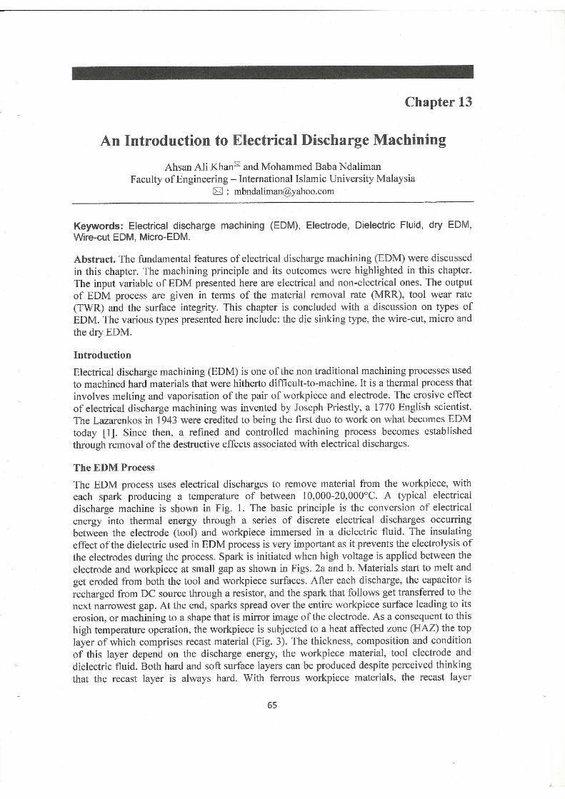
An Introduction to Electrical Discharge Machining
Chapter · October 2011
CITATIONS
2READS
5,529
2 authors:
Some of the authors of this publication are also working on these related projects:
Development of Brake Pads for Automobile using Seashell and Coconut Shell Reinforcement Material View project
Fabrication of Carbon Nanotube Reinforced MMC View project
Ahsan Ali Khan
International Islamic University Malaysia
113 PUBLICATIONS 1,007 CITATIONS
SEE PROFILE
M. B. Ndaliman
Federal University of Technology Minna
63 PUBLICATIONS 187 CITATIONS
SEE PROFILE
All content following this page was uploaded by M. B. Ndaliman on 28 August 2014.
The user has requested enhancement of the downloaded file.


Module 9
Non conventional Machining
Version 2 ME, IIT Kharagpur

Lesson 39
Electro Discharge
Machining
Version 2 ME, IIT Kharagpur

Instructional Objectives
(i) Identify electro-discharge machining (EDM) as a particular type of non-tradition processes
(ii) Describe the basic working principle of EDM process (iii) Draw schematically the basics of EDM (iv) Describe spark initiation in EDM (v) Describe material removal mechanism in EDM (vi) Draw the basic electrical waveform used in EDM (vii) Identify the process parameters in EDM (viii) Describe the characteristics of EDM (ix) Identify the purpose of dielectric fluid in EDM (x) List two common dielectric fluid (xi) Analyse the required properties of EDM tool (xii) List four common tool material for EDM (xiii) Develop models for material removal rate in EDM (xiv) Identify the machining characteristics in EDM (xv) Analyse the effect of process variables on surface roughness (xvi) Analyse taper cut and over cut in EDM (xvii) Identify different modules of EDM system (xviii) Draw schematic representation of different electrical generators
used in EDM (xix) Analyse working principle of RC type EDM generator
1. Introduction Electro Discharge Machining (EDM) is an electro-thermal non-traditional machining process, where electrical energy is used to generate electrical spark and material removal mainly occurs due to thermal energy of the spark. EDM is mainly used to machine difficult-to-machine materials and high strength temperature resistant alloys. EDM can be used to machine difficult geometries in small batches or even on job-shop basis. Work material to be machined by EDM has to be electrically conductive. 2. Process Fig. 1 shows schematically the basic working principle of EDM process.
V
I (-ve)
Fig. 1 Schematic representation of the basic working principle of EDM process.
Version 2 ME, IIT Kharagpur

In EDM, a potential difference is applied between the tool and workpiece. Both the tool and the work material are to be conductors of electricity. The tool and the work material are immersed in a dielectric medium. Generally kerosene or deionised water is used as the dielectric medium. A gap is maintained between the tool and the workpiece. Depending upon the applied potential difference and the gap between the tool and workpiece, an electric field would be established. Generally the tool is connected to the negative terminal of the generator and the workpiece is connected to positive terminal. As the electric field is established between the tool and the job, the free electrons on the tool are subjected to electrostatic forces. If the work function or the bonding energy of the electrons is less, electrons would be emitted from the tool (assuming it to be connected to the negative terminal). Such emission of electrons are called or termed as cold emission. The “cold emitted” electrons are then accelerated towards the job through the dielectric medium. As they gain velocity and energy, and start moving towards the job, there would be collisions between the electrons and dielectric molecules. Such collision may result in ionisation of the dielectric molecule depending upon the work function or ionisation energy of the dielectric molecule and the energy of the electron. Thus, as the electrons get accelerated, more positive ions and electrons would get generated due to collisions. This cyclic process would increase the concentration of electrons and ions in the dielectric medium between the tool and the job at the spark gap. The concentration would be so high that the matter existing in that channel could be characterised as “plasma”. The electrical resistance of such plasma channel would be very less. Thus all of a sudden, a large number of electrons will flow from the tool to the job and ions from the job to the tool. This is called avalanche motion of electrons. Such movement of electrons and ions can be visually seen as a spark. Thus the electrical energy is dissipated as the thermal energy of the spark. The high speed electrons then impinge on the job and ions on the tool. The kinetic energy of the electrons and ions on impact with the surface of the job and tool respectively would be converted into thermal energy or heat flux. Such intense localised heat flux leads to extreme instantaneous confined rise in temperature which would be in excess of 10,000oC. Such localised extreme rise in temperature leads to material removal. Material removal occurs due to instant vapourisation of the material as well as due to melting. The molten metal is not removed completely but only partially. As the potential difference is withdrawn as shown in Fig. 1, the plasma channel is no longer sustained. As the plasma channel collapse, it generates pressure or shock waves, which evacuates the molten material forming a crater of removed material around the site of the spark. Thus to summarise, the material removal in EDM mainly occurs due to formation of shock waves as the plasma channel collapse owing to discontinuation of applied potential difference. Generally the workpiece is made positive and the tool negative. Hence, the electrons strike the job leading to crater formation due to high temperature and melting and material removal. Similarly, the positive ions impinge on the tool leading to tool wear. In EDM, the generator is used to apply voltage pulses between the tool and the job. A constant voltage is not applied. Only sparking is desired in EDM rather than arcing. Arcing leads to localised material removal at a particular point whereas sparks get distributed all over the tool surface leading to uniformly distributed material removal under the tool. 3. Process Parameters The process parameters in EDM are mainly related to the waveform characteristics. Fig. 2 shows a general waveform used in EDM.
Version 2 ME, IIT Kharagpur

Fig. 2 Waveform used in EDM The waveform is characterised by the
• The open circuit voltage - Vo • The working voltage - Vw • The maximum current - Io • The pulse on time – the duration for which the voltage pulse is applied - ton • The pulse off time - toff • The gap between the workpiece and the tool – spark gap - δ • The polarity – straight polarity – tool (-ve) • The dielectric medium • External flushing through the spark gap.
4. Characteristics of EDM
(a) The process can be used to machine any work material if it is electrically conductive
(b) Material removal depends on mainly thermal properties of the work material rather than its strength, hardness etc
(c) In EDM there is a physical tool and geometry of the tool is the positive impression of the hole or geometric feature machined
(d) The tool has to be electrically conductive as well. The tool wear once again depends on the thermal properties of the tool material
(e) Though the local temperature rise is rather high, still due to very small pulse on time, there is not enough time for the heat to diffuse and thus almost no increase in bulk temperature takes place. Thus the heat affected zone is limited to 2 – 4 μm of the spark crater
Version 2 ME, IIT Kharagpur

(f) However rapid heating and cooling and local high temperature leads to surface hardening which may be desirable in some applications
(g) Though there is a possibility of taper cut and overcut in EDM, they can be controlled and compensated.
5. Dielectric In EDM, as has been discussed earlier, material removal mainly occurs due to thermal evaporation and melting. As thermal processing is required to be carried out in absence of oxygen so that the process can be controlled and oxidation avoided. Oxidation often leads to poor surface conductivity (electrical) of the workpiece hindering further machining. Hence, dielectric fluid should provide an oxygen free machining environment. Further it should have enough strong dielectric resistance so that it does not breakdown electrically too easily but at the same time ionise when electrons collide with its molecule. Moreover, during sparking it should be thermally resistant as well. Generally kerosene and deionised water is used as dielectric fluid in EDM. Tap water cannot be used as it ionises too early and thus breakdown due to presence of salts as impurities occur. Dielectric medium is generally flushed around the spark zone. It is also applied through the tool to achieve efficient removal of molten material. 6. Electrode Material Electrode material should be such that it would not undergo much tool wear when it is impinged by positive ions. Thus the localised temperature rise has to be less by tailoring or properly choosing its properties or even when temperature increases, there would be less melting. Further, the tool should be easily workable as intricate shaped geometric features are machined in EDM. Thus the basic characteristics of electrode materials are:
• High electrical conductivity – electrons are cold emitted more easily and there is less bulk electrical heating
• High thermal conductivity – for the same heat load, the local temperature rise would be less due to faster heat conducted to the bulk of the tool and thus less tool wear
• Higher density – for the same heat load and same tool wear by weight there would be less volume removal or tool wear and thus less dimensional loss or inaccuracy
• High melting point – high melting point leads to less tool wear due to less tool material melting for the same heat load
• Easy manufacturability • Cost – cheap
The followings are the different electrode materials which are used commonly in the industry:
• Graphite • Electrolytic oxygen free copper • Tellurium copper – 99% Cu + 0.5% tellurium • Brass
Version 2 ME, IIT Kharagpur

7. Modelling of Material Removal and Product Quality Material removal in EDM mainly occurs due to intense localised heating almost by point heat source for a rather small time frame. Such heating leads to melting and crater formation as shown in Fig. 3.
work piece
tool
Fig. 3 Schematic representation of crater formation in EDM process. The molten crater can be assumed to be hemispherical in nature with a radius r which forms due to a single pulse or spark. Hence material removal in a single spark can be expressed as
332 rs π=Γ
Now as per Fig. 2, the energy content of a single spark is given as Es = VIton
A part of this spark energy gets lost in heating the dielectric, and rest is distributed between the impinging electrons and ions. Thus the energy available as heat at the workpiece is given by
sw EE α
Ew = kEsNow it can be logically assumed that material removal in a single spark would be proportional to the spark energy. Thus
wss EE ααΓ
ss gE=Γ∴
Now material removal rate is the ratio of material removed in a single spark to cycle time. Thus
offon
s
c
s
tttMRR
+==
ΓΓ
⎟⎟⎠
⎞⎜⎜⎝
⎛+
=+
=
on
offoffon
on
tt1
VIgtt
VItgMRR
Version 2 ME, IIT Kharagpur

The model presented above is a very simplified one and linear relationship is not observed in practice. But even then such simplified model captures the complexity of EDM in a very efficient manner. MRR in practice does increase with increase in working voltage, current, pulse on time and decreases with increase in pulse off time. Product quality is a very important characteristic of a manufacturing process along with MRR. The followings are the product quality issues in EDM
• Surface finish • Overcut • Tapercut
No two sparks take place side by side. They occur completely randomly so that over time one gets uniform average material removal over the whole tool cross section. But for the sake of simplicity, it is assumed that sparks occur side by side as shown in Fig. 4.
Measure of roughness = hm
1st 2nd 3rd
Fig. 4 Schematic representation of the sparks in EDM process.
Thus
3sm r
32andrh πΓ ==
3/1
sm 23hr ⎟
⎠⎞
⎜⎝⎛==∴ Γ
Now onss gVItgE ==Γ
( ) { 3/1on
3/1sm VIth αΓα }∴
Thus it may be noted that surface roughness in EDM would increase with increase in spark energy and surface finish can be improved by decreasing working voltage, working current and pulse on time. In EDM, the spark occurs between the two nearest point on the tool and workpiece. Thus machining may occur on the side surface as well leading to overcut and tapercut as depicted in Fig. 5. Taper cut can be prevented by suitable insulation of the tool. Overcut cannot be prevented as it is inherent to the EDM process. But the tool design can be done in such a way so that same gets compensated.
Version 2 ME, IIT Kharagpur

Insulation
tapercut and overcut tapercut prevention Fig. 5 Schematic depiction of taper cut and over cut and control of taper cut 8. Equipment Fig. 6 shows an EDM machine. EDM machine has the following major modules
• Dielectric reservoir, pump and circulation system • Power generator and control unit • Working tank with work holding device • X-y table accommodating the working table • The tool holder • The servo system to feed the tool
9. Power generator Fig. 2 depicted general nature of voltage pulses used in electro-discharge machining. Different power generators are used in EDM and some are listed below:
Fig. 6 Commercial Electro-discharge Machine
• Resistance-capacitance type (RC type) Relaxation generator • Rotary impulse type generator • Electronic pulse generator • Hybrid EDM generator
Version 2 ME, IIT Kharagpur
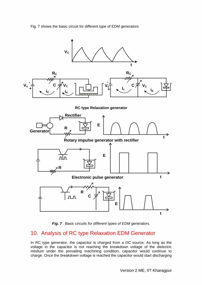
Fig. 7 shows the basic circuit for different type of EDM generators
RC type Relaxation generator
Fig. 7 Basic circuits for different types of EDM generators. 10. Analysis of RC type Relaxation EDM Generator In RC type generator, the capacitor is charged from a DC source. As long as the voltage in the capacitor is not reaching the breakdown voltage of the dielectric medium under the prevailing machining condition, capacitor would continue to charge. Once the breakdown voltage is reached the capacitor would start discharging
VC
t
RC
Vo VC C
iC id id
Ic
RC
C VC Vo -
+
- +
Rotary impulse generator with rectifier
Rectifier
R Generator
E
t
R
E
t Electronic pulse generator
R C
E
t
Version 2 ME, IIT Kharagpur

and a spark would be established between the tool and workpiece leading to machining. Such discharging would continue as long as the spark can be sustained. Once the voltage becomes too low to sustain the spark, the charging of the capacitor would continue. Fig. 8 shows the working of RC type EDM relaxation.
Fig. 8 Schematic of the working principle of RC type EDM relaxation circuit. During charging, at any instant, from circuit theory,
`
or dtCR
1VV
dVcco
=−
At t=0, Vc=0 and t = tc, Vc=Vc*
∫ ∫=−
∴*cV
0
ct
0cco
c dtCR
1VV
dV
( ) *cVoco
c
c VVlnRt
−=−⇒
⎪⎭
⎪⎬⎫
⎪⎩
⎪⎨⎧−=∴
−CcR
ct
oc e1V*V
⎪⎭
⎪⎬⎫
⎪⎩
⎪⎨⎧−=
−CcR
t
oc e1VVor
where, Ic = charging current Vo= open circuit voltage Rc= charging resistance C = capacitance Vc= instantaneous capacitor voltage during charging Thus at any instant charging current, ic, can be given as:
c
CcRt
oo
c
coc R
e1VV
RVVi
⎟⎟⎟
⎠
⎞
⎜⎜⎜
⎝
⎛−−
=−
=
−
Vo
RC
ic
VC C
Version 2 ME, IIT Kharagpur

CcRt
oc
CcRt
oc e.i
ReVi
−−
==
During discharging, the electrical load coming from the EDM may be assumed a totally resistive and is characterised by a machine resistance of Rm. then the current passing through the EDM machine is given by
dtdVC
RVi c
m
cd −==
where, Id = discharge current or current flowing through the machine Vc= instantaneous capacitor voltage during discharging Rm= machine resistance The negative sign in front of the derivative of the voltage represents that the Vc is gradually decreasing during discharging. Now at t = 0 (i.e. at the start of discharging, i.e. initiation of the spark), Vc=Vc* and at t = td, Vc=Vd*
∫∫ −=dt
0
*dV
*cV mc
c dtCR
1V
dV
*c
*d
m
d
VVln
CRt
=−∴
CmRdt
m
*c*
d e.RVV
−=∴
∴ The discharging or the machining current Id is given by
CmRt
m
*c
m
dd e.
RV
RV
i−
==
Thus the voltage and the current pulses during charging and discharging is given in Fig. 9.
Version 2 ME, IIT Kharagpur

Fig. 9 Schematic representation of the current pulses during charging and discharging in EDM process.
For maximum power dissipation in RC type EDM generator Vc* = 0.716 Vo. The charging time or idle time or off time, tc, can be expressed as
⎟⎟⎠
⎞⎜⎜⎝
⎛−
−=
c
*c
cc
VV1ln
CRt
The discharging time or machining time or on time can be expressed as
*
*c
d
md
VVln
CRt
⎟⎟⎠
⎞⎜⎜⎝
⎛−=
∴ Frequency of operation, f
⎟⎟⎠
⎞⎜⎜⎝
⎛+
⎟⎟⎠
⎞⎜⎜⎝
⎛−
=+
=
*c
d
m
c
*c
cdc
VVln
CR
VV1ln
CR1
tt1f
Total energy discharged through spark gap
dteRRVdtRi CmR
t2
mdt
0
dt
02m
2*c
m2d
−
∫ ∫==
dteRV dt
o
CmRt2
m
2*c ∫=
−
V
iC
id
tc td
Vc*
Vd*
Vo
t
t
t
Version 2 ME, IIT Kharagpur

dt
0
CmRt2
m
m
2*c e
t2CR.
RV −
−=
⎪⎭
⎪⎬⎫
⎪⎩
⎪⎨⎧−=
−CmRdt2
2*c e1CV
21
2*cCV
21
≅
Quiz Test 1. Which of the following material cannot be machined by EDM
(a) steel (b) WC (c) Titanium (d) Glass
2. w( W)hich of the following is used as dielectric medium in EDM
(a) tap water (b) kerosene (c) NaCL solution (d) KOH solution
3. Tool should not have
(a) low thermal conductivity (b) high machinability (c) high melting point (d) high specific heat
Problems 1. In a RC type generator, the maximum charging voltage is 80 V and the charging capacitor is 100 μF. Determine spark energy. 2. If in a RC type generator, to get an idle time of 500 μs for open circuit voltage of 100 V and maximum charging voltage of 70 V, determine charging resistance. Assume C = 100 μF. 3. For a RC type generator to get maximum power dissipation during charging Vc* = Vox0.716. Determine idle time for Rc = 10 Ω and C = 200 μF 4. Determine on time or discharge time if Vo = 100 V and Vd* = 15 V. Spark energy = 0.5 J. Generator is expected for maximum power during charging. Machine resistance = 0.5 Ω.
Version 2 ME, IIT Kharagpur

Solution to the Quiz Test 1 – (d) 2 – (b) 3 – (a) Solutions to the Problems Solution to Prob. 1
J32.080x10x100x21CV
21E 262
s === − answer
Solution to Prob. 2
⎟⎟⎠
⎞⎜⎜⎝
⎛−
−=
c
*c
cc
VV1ln
CRt
⎟⎠⎞
⎜⎝⎛ −
−=−
−
100701ln
10x100xR10x5006
c6
Ω6RC ≅ Answer
Solution to Prob. 3
( )716.01ln10x200x10
VV1ln
CRt6
o
*c
cc −
−=
⎟⎟⎠
⎞⎜⎜⎝
⎛−
−=−
tc = 1.58 ms answer Solution to Prob. 4
V6.71V716.0V o*c ==
J5.0CV21E 2
s ==
( )
F1956.71
1x5.0x2C 2 μ==∴
F62
VVln
CRt
*c
*d
md μ=
⎟⎟⎠
⎞⎜⎜⎝
⎛−= answer
Version 2 ME, IIT Kharagpur

Hitachi MetalsHitachi Metals
Printed in Japan ’17-2(D)CAT.NO.KM305B
Electrical Discharge Machining Wire 〈EDM wire〉
http://www.hitachi-metals.co.jp/e/
Hitachi Metals Singapore Pte. Ltd.
Cable Materials CompanyShinagawa Season Terrace, 2-70, Konan 1-chome, Minato-ku, Tokyo 108-8224, JapanTel : +81-3-6774-3636
Head Office12 Gul Avenue, Singapore 629656Tel : +65-6861-7711
Robofil is a registered trademark of Charmilles Technologies S.A.DWC is a registered trademark of Mitsubishi Electric Corporation.※Specifications subject to change without notice.
Hitachi Metals, Ltd.
All rights reserved

We satisfy customer demands by implementing integrated
production from casting to processing.
• The wire is manufactured and quality-controlled in Japan.
• Many W-EDM machine manufacturers recommend the use of our wire in their machines.
• Stable discharging is enabled with our wire, as carefully selected materials are used.
Electrical Discharge Machining Wire
Standard EDM wire
Special EDM wire
Guideline for selecting products
Introduction of products
Ordering products
Technical data
Positioning of each wire type ...................................................... 2
Cutting application of each wire type .......................................... 2
Table for checking paraffin presence .......................................... 3
Advantages of non-paraffin wire ................................................. 3
Product specifications ................................................................. 7
Spool specifications .................................................................... 7
Packing specifications ................................................................ 8
Setting cutting conditions ........................................................... 9
Problems and troubleshooting .................................................. 10
How to correct tangled wire ...................................................... 11
Optimization of cutting conditions ............................................ 12
BZ-B wire (Special brass: Increased zinc content) ..................... 5
TF wire (Alloy brass: Special metallic-element added) ................ 5
BZ-AT wire (Extra-soft brass: For taper cutting) .......................... 6
OFC wire (Oxygen free copper) ................................................... 6
BZ-U (BZ-K) wire (Standard brass: Equivalent to JIS C 2800) .... 4
BZ-MU wire (Standard brass: Equivalent to JIS C 2700) ............ 4
Guideline for selecting products
Setting cutting condition
Problems and troubleshooting
Optimization of cutting condition
1 2
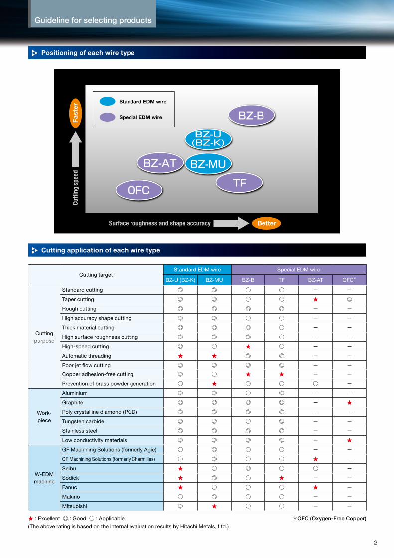
Positioning of each wire type
Cutting application of each wire type
Cutting targetStandard EDM wire Special EDM wire
BZ-U (BZ-K) BZ-MU BZ-B TF BZ-AT OFC*
Cutting purpose
Standard cutting ◎ ◎ ○ ○ − −
Taper cutting ◎ ◎ ○ ○ ★ ◎
Rough cutting ◎ ◎ ◎ ◎ − −
High accuracy shape cutting ◎ ◎ ○ ○ − −
Thick material cutting ◎ ◎ ◎ ○ − −
High surface roughness cutting ◎ ◎ ◎ ○ − −
High-speed cutting ◎ ○ ★ ○ − −
Automatic threading ★ ★ ◎ ◎ − −
Poor jet flow cutting ◎ ◎ ◎ ◎ − −
Copper adhesion-free cutting ◎ ○ ★ ★ − −
Prevention of brass powder generation ○ ★ ○ ○ ○ −
Work-piece
Aluminium ◎ ◎ ○ ◎ − −
Graphite ◎ ◎ ◎ ◎ − ★
Poly crystalline diamond (PCD) ◎ ◎ ◎ ◎ − −
Tungsten carbide ◎ ◎ ○ ◎ − −
Stainless steel ◎ ◎ ◎ ◎ − −
Low conductivity materials ◎ ◎ ◎ ◎ − ★
W-EDM machine
GF Machining Solutions (formerly Agie) ○ ◎ ○ ○ − −
GF Machining Solutions (formerly Charmilles) ○ ◎ ○ ○ ★ −
Seibu ★ ○ ◎ ○ ○ −
Sodick ★ ◎ ○ ★ − −
Fanuc ★ ○ ○ ○ ★ −
Makino ○ ◎ ○ ○ − −
Mitsubishi ◎ ★ ○ ○ − −
★ : Excellent ◎ : Good ○ : Applicable
(The above rating is based on the internal evaluation results by Hitachi Metals, Ltd.)
*OFC (Oxygen-Free Copper)
BZ-U(BZ-K)
TF
BZ-B
BZ-AT
OFC
BZ-MU
Cutti
ng s
peed
Fast
er
Surface roughness and shape accuracy Better
Standard EDM wire
Special EDM wire

Guideline for selecting products Introduction of products
3 4
Table for checking paraffin presence
Advantages of non-paraffin wire
W-EDM Machines Suitable TypeRemark
Maker Model Paraffin Non-paraffin
GF Machining Solutions(formerly Agie)
CUT (S,P,E,OilTech,TW) ─ ○
The non-paraffin type applies to all wire, regardless of size.
AGIE CUT (SF + HSS) ─ ○
Classic/Evolution/Excellence/Progress/Vertex
─ ○
GF Machining Solutions(formerly Charmilles)
Robofil® ─ ○
Seibu
MA/MMA/Super MMA/MB/MMB/Ultra MMB
─ ○
MS ─ ○
EW ─ ○
Sodick
AL/VL ○ ─For wire of φ0.15 mm or less, the non-paraffin type improves positioning accuracy.
AG/SL/AQ ○ ─
AP ○ ─
EXC ○ ─
Fanucα ─ ○ The non-paraffin type also applies to new
models (i.e.,α Series).Tape Cut ─ ○
Makino
U (H.E.A.T,j) ○ ─
For wire of φ0.15 mm or less, the non-paraffin type improves positioning accuracy.
W-FB ○ ─
EE ○ ─
EQH ○ ─
EC ○ ─
Mitsubishi
MV (S,R)/PA/MP/MX/NA (P)/BA/PA (M)
/FA (V,PS,M,VSM,PSM,VM,PM)/RA (MAT,M,AT)
─ ○ The non-paraffin type applies to all wire, regardless of size.
QA/FX (K)/CX,SX/DWC® ○ ─For wire of φ0.15 mm or less, the non-paraffin type improves positioning accuracy.
Deteriorated surface accuracy
Normal surface accuracy
・ Wire may easily slip on rollers, etc.・ Extraneous matter may remain on rollers, etc.
・ Degraded contact detection accuracy and positioning
・ Generation of unstable discharge with respect to weak discharge and a shorter service life of power feed dies
2. Insulating material remains on the wire surface, thereby causing:
If wire has excessive paraffin or contamination
・ Unstable travel of the wire and degraded surface accuracy
・ Trouble in automatic threading and stoppage of the W-EDM machine triggered by guide dies being blocked
1. Extraneous matter or oil remains, thereby causing:
If paraffin wire is used on the W-EDM machine that is specifically calibrated for non-paraffin wire, the characteristics of electrical discharge machining may be adversely affected since the wire travel system will become unstable due to sliding, etc.Sufficient care must be taken when selecting wire, as cutting seams (called wire marks) are frequently formed, particularly on the cutting surface.

Guideline for selecting products Introduction of products
3 4
Guideline for selecting products Introduction of products
3 4
StandardEDM wire BZ-U (BZ-K) wire
StandardEDM wire BZ-MU wire
Hard wireCapable of automatic threading
Hard wire
Soft wire
Capable of automatic threadingBrass powder reduction
▶Hitachi Metals' standard brass wire
▶High cutting speed due to zinc-rich constitution
▶Improved automatic threading capability due to excellent straightness of wire
▶Applicable for use on W-EDM machines of respective companies equipped with an automatic threading function.
▶Significant reduction of brass powder adhered to cutting surface
▶Improved automatic threading capability due to excellent straightness of wire
▶Applicable for use on all models of W-EDM machines of pipe, jet or anneal systems equipped with an automatic threading function.
Type Product nameStandard size*1
(φmm/inch)Wire tolerance
(mm/inch)Tensile strength
(MPa)Elongation
(%)
H (Hard)BZ-U
(BZ-K)
0.10/0.004±0.001/±0.00004
Min 980
Min 0.4
0.15/0.006
0.20/0.008-0.002~0/
-0.00008~00.25/0.010
Min 9320.30/0.012
Type Product nameStandard size*1
(φmm/inch)Wire tolerance
(mm/inch)Tensile strength
(MPa)Elongation
(%)
H (Hard) BZ-MU
0.10/0.004±0.001/±0.00004
Min 980
Min 0.4
0.15/0.006
0.20/0.008-0.002~0/
-0.00008~00.25/0.010
Min 9320.30/0.012
A (Soft) BZ
0.10/0.004±0.001/±0.00004
Min 441 Min 15
0.15/0.006
0.20/0.008-0.002~0/
-0.00008~00.25/0.010
0.30/0.012
General characteristics of BZ-U wire
General characteristics of BZ-MU wire
Note: *1 Please contact us for the availability of custom sizes, other than standard sizes.▶ The paraffin or non-paraffin type is specifiable. Please see “Table for checking paraffin presence” on page 3 for applicable W-EDM machines.▶ BZ-K is the product name in North America.
Note: *1 Please contact us for the availability of custom sizes, other than standard sizes.▶ The paraffin or non-paraffin type is specifiable. Please see “Table for checking paraffin presence” on page 3 for applicable W-EDM machines.
Standard brass
JIS C 2800equivalent
Standard brass
JIS C 2700equivalent

Introduction of products
5 6
SpecialEDM wire BZ-B wire
SpecialEDM wire TF wire
Type Product nameStandard size*1
(φmm/inch)Wire tolerance
(mm/inch)Tensile strength
(MPa)Elongation
(%)
H (Hard)
BZ-B
0.10/0.004±0.001/±0.00004
Min 883
Min 0.4
0.15/0.006
0.20/0.008-0.002~0/
-0.00008~00.25/0.010
Min 7840.30/0.012
A (Soft)
0.10/0.004±0.001/±0.00004
Min 441 Min 12
0.15/0.006
0.20/0.008-0.002~0/
-0.00008~00.25/0.010
0.30/0.012
Type Product nameStandard size*1
(φmm/inch)Wire tolerance
(mm/inch)Tensile strength
(MPa)Elongation
(%)
H (Hard)
TF
0.10/0.004±0.001/±0.00004
Min 980
Min 0.4
0.15/0.006
0.20/0.008-0.002~0/
-0.00008~00.25/0.010
Min 9320.30/0.012
A (Soft)
0.10/0.004±0.001/±0.00004
Min 441 Min 10
0.15/0.006
0.20/0.008-0.002~0/
-0.00008~00.25/0.010
0.30/0.012
General characteristics of BZ-B wire
General characteristics of TF wire
Special brass
Zinc contentincreased
Alloy brass
Specialmetallic-element added
Improvement in surface accuracy
Soft wireHard wire
Brass adhesion preventionHigh-speed cutting
Soft wire
Hard wireBrass adhesion preventionBreaking prevention
▶Enhanced surface accuracy and processing speed due to the increased zinc-rich characteristic more than BZ-U
▶ Significantly reduced amount of brass adhesion on the cutting surface by increasing the amount of zinc
▶Superior high-temperature strength achieved by adding special metallic elements to prevent breakage
▶Particularly effective for cutting thick objects (100 mm or more in thickness)
▶Significantly reduced amount of brass adhesion on the cutting surface by adding special metallic elements
Note: *1 Please contact us for the availability of custom sizes, other than standard sizes.▶ The paraffin or non-paraffin type is specifiable. Please see “Table for checking paraffin presence” on page 3 for applicable W-EDM machines.
Note: *1 Please contact us for the availability of custom sizes, other than standard sizes.▶ The paraffin or non-paraffin type is specifiable. Please see “Table for checking paraffin presence” on page 3 for applicable W-EDM machines.

Introduction of products
5 6
Introduction of products
5 6
SpecialEDM wire BZ-AT wire
SpecialEDM wire OFC*2 wire
Type Product nameStandard size*1
(φmm/inch)Wire tolerance
(mm/inch)Tensile strength
(MPa)Elongation
(%)
A (Soft) BZ-AT
0.20/0.008-0.002~0/
-0.00008~0
Max 490
Min 250.25/0.010Max 450
0.30/0.012
Type Product nameStandard size*1
(φmm/inch)Wire tolerance
(mm/inch)Tensile strength
(MPa)Elongation
(%)
H (Hard)
1OFC-ED
0.20/0.008-0.002~0/
-0.00008~0Min 441 Min 0.30.25/0.010
0.30/0.012
A (Soft)
0.20/0.008-0.002~0/
-0.00008~0Max 274 Min 150.25/0.010
0.30/0.012
General characteristics of BZ-AT wire
General characteristics of OFC wire
Oxygen freecopper
99.9% or more
Ultra-soft brass
▶Particularly effective for taper cutting thanks to extreme softness achieved by special heat processing
▶Shows the effect especially in wide-angle (20 to 45°) taper cutting.
▶Wire for the old model W-EDM machines (for which copper wire is recommended)
▶Effective for sintered material such as graphite and for vacuum
Note: *1 Please contact us for the availability of custom sizes, other than standard sizes.▶ The paraffin or non-paraffin type is specifiable. Please see “Table for checking paraffin presence” on page 3 for applicable W-EDM machines.
Ultra-soft wireWide-angle taper cutting
Soft wireHard wireCopper wire
Note: *1 Please contact us for the availability of custom sizes, other than standard sizes. *2 OFC: Oxygen-Fee Copper▶ The paraffin or non-paraffin type is specifiable.

Ordering products
7 8
Product category Type Product nameStandard size*1
(φmm/inch)Wire tolerance
(mm/inch)Tensile strength
(MPa)Elongation
(%)
Standard EDM wire
H (hard)BZ-U
(BZ-K)BZ-MU
0.10/0.004±0.001/±0.00004
Min 980Min 0.4
0.15/0.0060.20/0.008
-0.002~0/-0.00008~00.25/0.010Min 932
0.30/0.012
A (soft) BZ
0.10/0.004±0.001/±0.00004
Min 441 Min 150.15/0.0060.20/0.008
-0.002~0/-0.00008~00.25/0.0100.30/0.012
SpecialEDM Wire
H (hard) BZ-B
0.10/0.004±0.001/±0.00004
Min 883Min 0.4
0.15/0.0060.20/0.008
-0.002~0/-0.00008~00.25/0.010Min 784
0.30/0.012
A (soft) BZ-B
0.10/0.004±0.001/±0.00004
Min 441 Min 120.15/0.0060.20/0.008
-0.002~0/-0.00008~00.25/0.0100.30/0.012
H (hard) TF
0.10/0.004±0.001/±0.00004
Min 980Min 0.4
0.15/0.0060.20/0.008
-0.002~0/-0.00008~00.25/0.010Min 932
0.30/0.012
A (soft) TF
0.10/0.004±0.001/±0.00004
Min 441 Min 100.15/0.0060.20/0.008
-0.002~0/-0.00008~00.25/0.0100.30/0.012
A (ultra-soft) BZ-AT0.20/0.008
-0.002~0/-0.00008~0Max 490
Min 250.25/0.010Max 450
0.30/0.012
H (hard) 1OFC-ED0.20/0.008
-0.002~0/-0.00008~0 Min 441 Min 0.30.25/0.0100.30/0.012
A (soft) 1OFC-ED0.20/0.008
-0.002~0/-0.00008~0 Max 274 Min 150.25/0.0100.30/0.012
Product specifications
Spool names and dimensions
Spool nameFlange
diameterD(mm/inch)
Barrel diameter
d(mm/inch)
Outer widthL(mm/inch)
Flange thickness
a(mm/inch)
Arbor hole diameter
h(mm/inch)
Winding weight
(kg/pound)Spool dimensions
P-5RTS 130/5.1 80/3.1 110/4.3 10/0.4 20/0.8 3.0/6.6
P-5RT 160/6.3 90/3.5 114/4.5 12/0.5 20/0.8 5.0/11.0
P-5RTX 160/6.3 90/3.5 114/4.5 12/0.5 20/0.8 6.0/13.2
P-10 200/7.9 110/4.3 134/5.3 12/0.5 25/1.0 10.0/22.0
P-15L 250/9.8 125/4.9 140/5.5 15/0.6 34/1.3 20.0/44.0
P-30 280/11.0 200/7.9 220/8.7 20/0.8 73/2.9 30.0/66.0
K-125 125/4.9 80/3.1 125/4.9 12.5/0.4 16/0.6 3.0/6.6
K-160 160/6.3 100/3.9 160/6.3 16/0.6 22/0.9 6.0/13.2
K-160L 160/6.3 100/3.9 160/6.3 16/0.6 22/0.9 7.0/15.4
K-160X 160/6.3 100/3.9 160/6.3 16/0.6 22/0.9 7.95/17.5
K-200 200/7.9 125/4.9 200/7.9 20/0.8 22/0.9 15.0/33.0
K-200X 200/7.9 125/4.9 200/7.9 20/0.8 22/0.9 15.91/35.0
K-250 250/9.8 160/6.3 200/7.9 20/0.8 22/0.9 25.0/55.0
h d D
aL
Note: *1 Please contact us for the availability of custom sizes, other than standard sizes.

Ordering products
7 8
Ordering products
7 8
Spool nameWinding weight
(kg/pound)
Quantity packed in a carton box (pcs/box)
Carton box sizeL×W×H(mm/inch) Color Carton box dimensions
P-5RTS 3.0/6.6 4
370×290×200/14.6×11.4×7.9Red
P-5RT 5.0/11.04
P-5RTX 6.0/13.2
P-10 10.0/22.0 2 303×209×275/11.9×8.2×10.8
P-15L 20.0/44.01
300×210×290/11.8×8.3×11.4 GreenP-30 30.0/66.0 307×285×322/12.1×11.2×12.7 Red
K-125 3.0/6.6 4
370×290×200/14.6×11.4×7.9
Blue
K-160 6.0/13.2
2K-160L 7.0/15.4
K-160X 7.95/17.5
K-200 15.0/33.0
1300×210×290/11.8×8.3×11.4
K-200X 15.91/35.0
K-250 25.0/55.0 286×257×280/11.3×10.1×11.0
Packing Specifications
Standard EDM wire Special EDM wire
Spool name
Wire size (Actual diameter x 100)
Paraffin classification: “(N)” to be indicated for non-paraffin wire
Product name
Type
(Unit in mm)H 2 0 P 5 R TBZ-U (N)
Typical model name: For non-paraffin wire
...For BZ-U non-paraffin wire
■Please place an order according to the following format:
Color
H
W
L

Technical data
9 10
Setting cutting conditions (to increase cutting speed)
YES
YES
YES
YES
YES
NO NO
NO
NO
NO
NO
Was the cutting speed increased?
Was the cutting speed increased?
Was the cutting speed increased?
Completion of setting
Contact us.
Was the cutting speed increased?
Did wire-breaking or unstable electrical discharge occur?
(Example) Tuning of Mitsubishi W-EDM machine
Change the wire without changing the cutting conditions.
Raise IP by 1 or 2 notches.
Next, lower SB or VG by 2 or3 notches.
Lower SB/VG by 2 or 3 notches without changing IP.
Lower IP by 1 notch, or raiseVG by 1 notch.
W-EDM machine makers Discharge energy setting Off-time setting
GF Machining Solutions (formerly Agie) P, T TD
GF Machining Solutions (formerly Charmilles) A, IAL B, Aj
Seibu I OFF
Sodick IP, ON MA, OFF
Fanuc VM, ON OFF
Makino Peak current, ON OFF
Mitsubishi IP SB, OFF
● Parameters for W-EDM machines of respective manufacturers
• Reference: How much the electrical discharge energy can be raised depends on the material thickness. Superior cutting conditions may be achieved by changing the settings according to the material thickness described below.
Material thickness Setting point
20mm or less- Basically, lesser electrical discharge power is required for thinner workpiece.- A significant increase in speed is not allowed with thinner plates, for which acceleration is limited to being low.- The amount of discharging energy allowed to increase for material with a thickness of 10 mm or less is also small.
20-60 mm- If the condition of a high-pressure jet stream is good, the machining efficiency will be improved.- For cutting a flat plate, place the nozzle as closely to the plate as possible.- A further increase in discharge energy is possible, given the better discharge of cutting sludge.
60mm or more
- Generally, more wire is consumed and susceptible to breaking more with a thicker plate.- The cutting speed may be increased by raising the wire speed.- Significant changes in conditions are possible, as the EDM wire shows a significant difference from brass wire in this range of thickness.
Note: As an optimal setting point varies depending on actual cutting conditions and other factors, please review the above-mentioned items so as to match the settings regarding your specific situation. Please contact us if you have any questions.

Technical data
9 10
Technical data
9 10
1. Wire breaking ①Breaking near feed plate - Feed plate in friction Check the feed plate and replace it periodically.
- No striking of water from the feed plate nozzle
Clean the feed plate nozzle and check water pressure.
②Breaking near wire guide - Dirty wire guide Perform periodic maintenance.
- Excessively strong holding force of the wire guide Make adjustment for optimal holding force.
- Misaligned wire guide Reset positioning accuracy.
③Breaking when idling - Poor wire hooking Check wire hooking position.
- Wire winding crossed (tangled, passing beneath another)
Replace or wind off wire.
④Breaking immediately after the start of cutting or within 5 mm
- Air mixed in the cutting liquid (breaking in air)
Degrease and wash the object subject to cutting, as cutting conditions are very strict.
- Tilted object subject to cutting Check water pressure of machining liquid.
Start cutting after plumbing.
⑤ Breaking after cutting 5 mm or more
- Low pressure of cutting liquidCheck for positioning error of cutting liquid nozzle and wear.
- Mismatched cutting conditionsCheck for dirt of suction opening of cutting liquid supply tank.
- Existence of foreign material or pinhole within the object
Check the cutting liquid evacuation route when cutting an object in a complex shape.
- Defective wire Replace wire.
- Poor travel of wireCheck for friction, cracks, and dirt of urethane rubber roller.
Correct setting error of wire tension.
2. Error of cutting accuracy
①Shaping defect - Insufficient pressing force of wire guide and positioning error
Adjust pressing force of wire guide and position.
- Insufficient wire tension Properly set wire tension.
- Large fluctuation in ambient temperature Remove material distortion (stress).
- Non-uniform cutting materials Erroneous plumbing of wire.
- Improper offsetClean and maintain guide dies and associated components.
3. Error of surface accuracy
①Rough surface - Mismatched cutting conditions (non-uniform electric discharge)
Increase wire transfer speed.
②Wire mark on cutting surface - Insufficient wire tension Increase cutting speed.
③Unstable cutting speed - Excessively slow cutting speedReplace ion-exchange resin and stabilize water specific resistance.
- Degraded ion-exchange resinClean and maintain the wire travel system (i.e., guiding system).
- Traveling fault of wireClean, maintain, and check consumption of the power feeder.
- Friction, crack or dirt of urethane roller
- Improper wire tension
4. Faulty cutting speed
①Increase of cutting speed disabled
- Mismatched cutting conditions (improper material, workpiece thickness, or size)
Match cutting conditions with those listed in the instruction manual.
Check positions and wear of upper and lower nozzles.
5. Curl failure ①Irregular storage of wire within the scrap box (wire running wild to form permanent waves)
- Uneven remnant stress of wireIncrease applied current by 1 TAP (higher cutting speed).
- Uneven wear of conveyor roller beltReplace wire when uneven wear occurs or wear exceeds 1/3 of wire diameter.
- Positioning error of conveyor roller beltConsult with maintenance contractor of W-EDM machine.
- Improper pressing force of conveyor roller belt Run wire with pressing force suitable for wire used.
- Large irregularity in wire shapeReplace the wire with one from a lot having proper straightness.
Problems and troubleshooting
Trouble Phenomenon Cause Check item/Solution
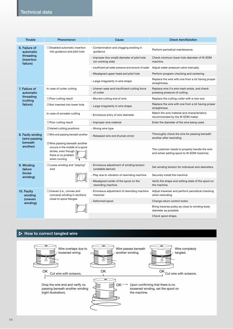
Technical data
11 12
How to correct tangled wire
6. Failure of automatic threading (insertion failure)
①Disabled automatic insertion into guidance and pilot hole
- Contamination and clogging existing in guidance
Perform periodical maintenance.
- Improper (too small) diameter of pilot hole (on working side)
Check minimum lower hole diameter of W-EDM machine.
- Insufficient jet water pressure and amount of water Adjust water pressure valve manually.
- Misaligned upper head and pilot hole Perform program checking and centering.
- Large irregularity in wire shapeReplace the wire with one from a lot having proper straightness.
7. Failure of automatic threading (cutting failure)
In case of cutter cutting - Uneven wear and insufficient cutting force of cutter
Replace wire if a wire mark exists, and check pressing pressure of cutting.
①Poor cutting result - Blurred cutting end of wire Replace the cutting cutter with a new one.
②Not inserted into lower hole - Large irregularity in wire shapeReplace the wire with one from a lot having proper straightness.
In case of annealer cutting - Erroneous entry of wire diameterMatch the wire material and characteristics recommended by the W-EDM maker.
①Poor cutting result - Improper wire material Enter the diameter of the wire being used.
②Varied cutting positions - Wrong wire type
8. Faulty winding (wire passing beneath another)
①Wire end passing beneath another - Released wire end (human error)Thoroughly check the wire for passing beneath another after rewinding.
②Wire passing beneath another occurs in the middle of a spool stroke, even though there is no problem when running
The customer needs to properly handle the wire end (when setting spool to W-EDM machine).
9. Winding failure (loose winding)
①Loose winding and “playing” wire
- Erroneous adjustment of winding tension (unstable dancer)
Set winding tension for individual wire diameters.
- Play due to vibration of rewinding machine Securely install the machine.
- Misaligned center of the spool on the rewinding machine
Verify the shape and setting state of the spool on the machine.
10. Faulty winding (uneven winding)
①Uneven (i.e., convex and concave) winding in sections close to spool flanges
- Erroneous adjustment of rewinding machine traverser
Adjust traverser and perform periodical checking when rewinding.
- Deformed spool Change return control motor.
Bring traverse pulley as close to winding body diameter as possible.
Check spool shape.
Trouble Phenomenon Cause Check item/Solution
Wire overlaps due to loosened wiring.
Cut wire with scissors. Cut wire with scissors.
Drop the wire end and verify no passing beneath another winding (right illustration).
Upon confirming that there is no loosened winding, set the spool on the machine.
Wire passes beneath another winding.
Wire complexly tangled.
OK
OK OK OK

Technical data
11 12
Technical data
11 12
Optimization of cutting conditions (Example) In case of an W-EDM machine manufactured by Mitsubishi
Problems Countermeasures
When not using PM control
Frequent wire breaking during 1st cut
Short circuit during 1st cut
Slow cutting speed during 1st cut
Wire breaking in collection pipe
Use PM control.
①Lower WT by 1 or 2 notches.
②Contact the service engineer.
①Raise SE by 1 notch.
②Lower SA by 1 notch.
①Raise VG by 2 to 8 notches.
②Raise SE by 1 notch.
①Lower SB by 1 to 3 notches.
②Lower VG by 2 to 5 notches.
③Lower IP by 1 notch.
●How to change cutting conditions In case of cutting AISI D2, 60 t with φ0.2 wire *For a reference only. [AE: 21 notches, SE: 1 notch used]
●Case of rough cutting (1st cut)
Standard value Adjustment value
Types of materialAISI D2
DIN 1.2363AISI P25
DIN 1.2330
AISI 1045
DIN C45
Stainless
steelAluminum Copper
Tungsten carbide
copper tungstenGraphite
Voltage switching
Vo (Notch) 12 0 0 0 0 0 0 +4
Cutting setting IP (Notch) 9 0 -1 0 0 -1 -1 -2
Off-time OFF (Notch) 1 0 0 0 0 0 0 0
Stabilizer A SA (Notch) 3 0 0 0 0 0 0 -2
Stabilizer B SB (Notch) 10 +2 +2 +2 +3 0 0 +4
Wire tension WT (Notch) 8 0 0 0 0 0 0 -1
Average cutting voltage VG (V) 39 0 0 +2 0 +8 +5 +15
Actual cutting speed FA (%) 100 90 85 85 200 85 50 +40
Standard value Correction value
Types of materialAISI D2
DIN 1.2363Either nozzle
separated
Both nozzle
separated
Stepped
workpiece
Taper 3
degrees
Taper 5
degrees
Taper 10
degrees
Taper 15
degrees
Voltage switching
Vo (Notch) 12 0 0 0 0 0 0 0
Cutting setting IP (Notch) 9 -1 -1 -2 0 0 -2 -2
Off-time OFF (Notch) 1 0 0 0 0 0 0 0
Stabilizer A SA (Notch) 3 0 0 0 0 0 0 -1
Stabilizer B SB (Notch) 10 +2 +2 -1 +2 +2 +3 +3
Wire tension WT (Notch) 8 0 0 0 -1 -1 -2 -3
Average cutting voltage VG (V) 39 0 +4 +4 0 +5 +5 +10
Actual cutting speed FA (%) 100 80 60 60 90 85 70 50
*Wire breaking can be reduced by raising the SE notch from 1→2→3→4→5.
1. In case of each workpiece
2. In case of each cutting purpose

Technical data
13
* When cutting speed is too high, take measures opposite to the above.
●Concaved center
●Variance existing in upper/lower dimensions
●Barrel-shaped
(Lower 2nd SB by 1 to 4 notches.)
(Lower 2nd Vo by 1 to 2 notches.)
(Lower 2nd VG by 2 to 5 notches.)
(Same as above.)
(Raise WS by 2 to 4 notches.)
(Raise WS by 2 to 4 notches.)
(Increase the amount by 2 to 7 µm.)
(Increase the amount by 2 to 10 µm.)
(Lower 2nd VG by 2 to 5 notches.)
(Lower 2nd SB by 1 to 3 notches.)
①Raise 2nd cutting speed.
①Raise 2nd cutting speed.
②Raise wire feeding speed.
①Raise wire feeding speed.
②Increase the amount of approach from 1st to 2nd.
①Decrease the amount of approach from 1st to 2nd.
①Lower 2nd cutting speed.
[When short circuit occurs]
[When FC=0 occurs]
①Decrease approach amount between IP:4 and IP:3 by 1 to 5 µm.
②Raise VG of IP:4 by 1 to 5 notches.
③Raise Vo of IP:3 by 2 to 4 notches.
④Perform the“Plus-One”cutting (see the following item).
①Lower, by 3 to 8 notches, the VG of cutting conditions under which “FC = 0” occurs.
②Decrease the amount of approach from 1st to 2nd by 5 to 10 µm.
Cutting speed falls compared with [1st] standard cutting.
Optimal [2nd] cutting speed is 1.5 to 2.3 times of FA.
Optimal [3rd] cutting speed is 2.0 to 2.5 times of FA.
IP:3 (Stable when cutting voltage V is VG +3 to +15 V)
Optimal [4th] cutting speed is 2.0 to 2.5 times of FA.
IP:2 (Stable when cutting voltage V is VG +5 to +15 V)
When slow →
When slow →
When slow →
When slow →
・Raise IP by 1 notch.・Raise SB by 1 to 2 notches.
・Raise Vo by 1 to 2 notches.・Lower SB by 1 to 4 notches.
・Raise Vo by 2 to 4 notches.・Lower VG by 2 to 5 notches.
・Raise Vo by 2 to 4 notches.・Lower VG by 2 to 5 notches.
●Concaved center and variance existing in upper/lower dimensions
●Bullet-shaped and variance existing in upper/lower dimensions
* For the case of cutting a thicker plate (60 mm or more), where the upper and lower nozzles are significantly spaced apart, ensure a working fluid flow rate of 1.5 to 2.0 L from the 2nd cutting and thereafter (for the purpose of preventing a short circuit and dropped speed at IP:3 or less).
Optimization of cutting conditions (Example) In case of an W-EDM machine manufactured by Mitsubishi
●Improvement of cutting precision (For punch shape)
●When seams are formed on cutting surface
●Tips on finish cutting (points to be checked during cutting)

Hitachi MetalsHitachi Metals
Printed in Japan ’17-2(D)CAT.NO.KM305B
Electrical Discharge Machining Wire 〈EDM wire〉
http://www.hitachi-metals.co.jp/e/
Hitachi Metals Singapore Pte. Ltd.
Cable Materials CompanyShinagawa Season Terrace, 2-70, Konan 1-chome, Minato-ku, Tokyo 108-8224, JapanTel : +81-3-6774-3636
Head Office12 Gul Avenue, Singapore 629656Tel : +65-6861-7711
Robofil is a registered trademark of Charmilles Technologies S.A.DWC is a registered trademark of Mitsubishi Electric Corporation.※Specifications subject to change without notice.
Hitachi Metals, Ltd.
All rights reserved
Electrical Discharge Machining (EDM)
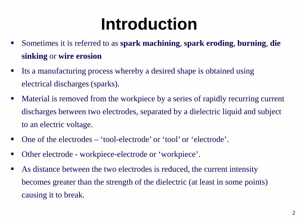
2
Sometimes it is referred to as spark machining, spark eroding, burning, die sinking or wire erosion
Its a manufacturing process whereby a desired shape is obtained using electrical discharges (sparks).
Material is removed from the workpiece by a series of rapidly recurring current discharges between two electrodes, separated by a dielectric liquid and subject to an electric voltage.
One of the electrodes – ‘tool-electrode’ or ‘tool’ or ‘electrode’.
Other electrode - workpiece-electrode or ‘workpiece’.
As distance between the two electrodes is reduced, the current intensity becomes greater than the strength of the dielectric (at least in some points) causing it to break.
Introduction

3
This allows current to flow between the two electrodes.
This phenomenon is the same as the breakdown of a capacitor.
As a result, material is removed from both the electrodes.
Once the current flow stops, new liquid dielectric is usually conveyed into the electrode zone enabling the solid particles (debris) to be carried away.
Adding new liquid dielectric in the electrode volume is commonly referred to as flushing.
Also, after a current flow, a difference of potential between the two electrodes is restored to what it was before the breakdown, so that a new liquid dielectric breakdown can occur.
History

4
In 1770, English Physicist Joseph Priestley studied the erosive effect of electrical discharges.
Furthering Priestley's research, the EDM process was invented by two Russian scientists, Dr. B.R. Lazarenko and Dr. N.I. Lazarenko in 1943.
In their efforts to exploit the destructive effects of an electrical discharge, they developed a controlled process for machining of metals.
Their initial process used a spark machining process, named after the succession of sparks (electrical discharges) that took place between two electrical conductors immersed in a dielectric fluid.
The discharge generator effect used by this machine, known as the Lazarenko Circuit, was used for many years in the construction of generators for electrical discharge.
History
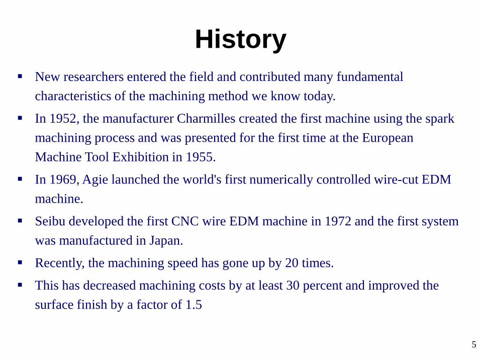
5
New researchers entered the field and contributed many fundamental characteristics of the machining method we know today.
In 1952, the manufacturer Charmilles created the first machine using the spark machining process and was presented for the first time at the European Machine Tool Exhibition in 1955.
In 1969, Agie launched the world's first numerically controlled wire-cut EDM machine.
Seibu developed the first CNC wire EDM machine in 1972 and the first system was manufactured in Japan.
Recently, the machining speed has gone up by 20 times.
This has decreased machining costs by at least 30 percent and improved the surface finish by a factor of 1.5
History

6
EDM is a machining method primarily used for hard metals or those that would be very difficult to machine with traditional techniques.
EDM typically works with materials that are electrically conductive, although methods for machining insulating ceramics with EDM have been proposed.
EDM can cut intricate contours or cavities in hardened steel without the need for heat treatment to soften and re-harden them.
This method can be used with any other metal or metal alloy such as titanium, hastelloy, kovar, and inconel.
Also, applications of this process to shape polycrystalline diamond tools have been reported.
General Aspects of EDM

7
EDM - System
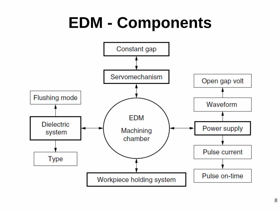
8
EDM - Components

9
The main components in EDM:
Electric power supply
Dielectric medium
Work piece & tool
Servo control unit.
The work piece and tool are electrically connected to a DC power supply.
The current density in the discharge of the channel is of the order of 10000 A/cm2 and power density is nearly 500 MW/cm2.
A gap, known as SPARK GAP in the range, from 0.005 mm to 0.05 mm is maintained between the work piece and the tool.
Dielectric slurry is forced through this gap at a pressure of 2 kgf/cm2 or lesser.
EDM - Components

10
It is a process of metal removal based on the principle of material removal by an interrupted electric spark discharge between the electrode tool and the work piece.
In EDM, a potential difference is applied between the tool and workpiece.
Essential - Both tool and work material are to be conductors.
The tool and work material are immersed in a dielectric medium.
Generally kerosene or deionised water is used as the dielectric medium.
A gap is maintained between the tool and the workpiece.
Depending upon the applied potential difference (50 to 450 V) and the gap between the tool and workpiece, an electric field would be established.
Generally the tool is connected to the negative terminal (cathode) of the generator and the workpiece is connected to positive terminal (anode).
EDM – Working Principle

11
As the electric field is established between the tool and the job, the free electrons on the tool are subjected to electrostatic forces.
If the bonding energy of the electrons is less, electrons would be emitted from the tool.
Such emission of electrons are called or termed as ‘cold emission’.
The “cold emitted” electrons are then accelerated towards the job through the dielectric medium.
As they gain velocity and energy, and start moving towards the job, there would be collisions between the electrons and dielectric molecules.
Such collision may result in ionization of the dielectric molecule.
Ionization depends on the ionization energy of the dielectric molecule and the energy of the electron.
EDM – Working Principle

12
As the electrons get accelerated, more positive ions and electrons would get generated due to collisions.
This cyclic process would increase the concentration of electrons and ions in the dielectric medium between the tool and the job at the spark gap.
The concentration would be so high that the matter existing in that channel could be characterised as “plasma”.
The electrical resistance of such plasma channel would be very less.
Thus all of a sudden, a large number of electrons will flow from tool to job and ions from job to tool.
This is called avalanche motion of electrons.
Such movement of electrons and ions can be visually seen as a spark.
Thus the electrical energy is dissipated as the thermal energy of the spark.
EDM – Working Principle

13
The high speed electrons then impinge on the job and ions on the tool.
The kinetic energy of the electrons and ions on impact with the surface of the job and tool respectively would be converted into thermal energy or heat flux.
Such intense localized heat flux leads to extreme instantaneous confined rise in temperature which would be in excess of 10,000oC.
Such localized extreme rise in temperature leads to material removal.
Material removal occurs due to instant vaporization of the material as well as due to melting.
The molten metal is not removed completely but only partially.
EDM – Working Principle
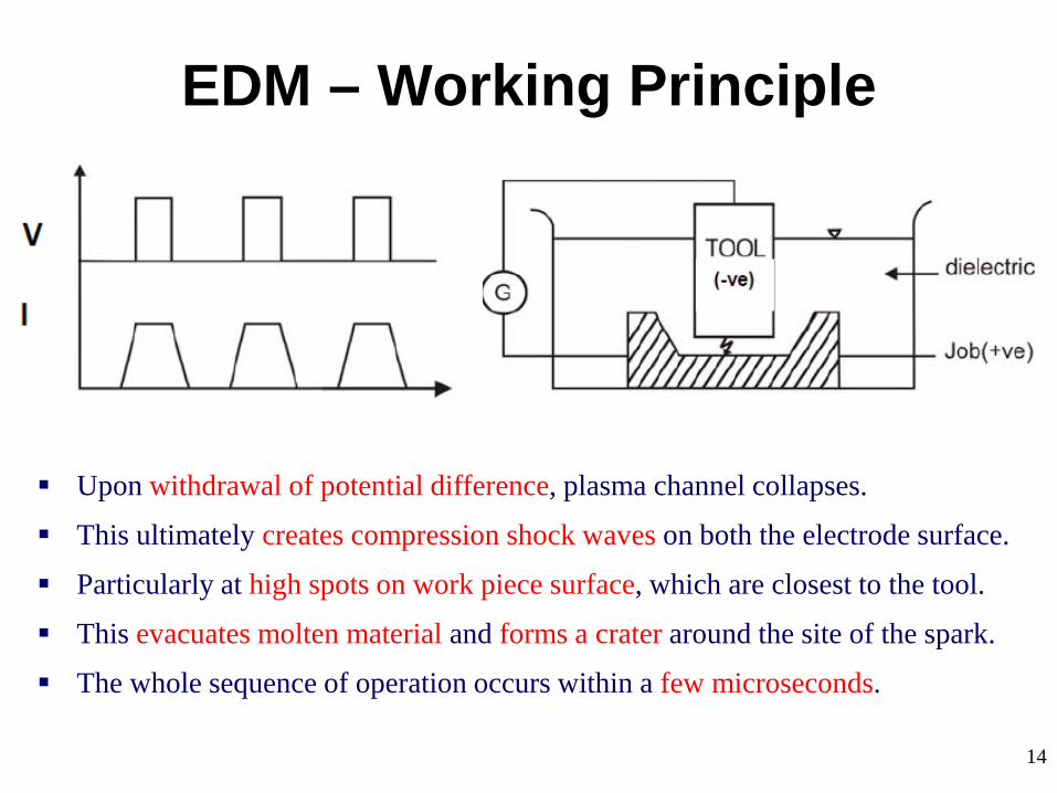
14
Upon withdrawal of potential difference, plasma channel collapses.
This ultimately creates compression shock waves on both the electrode surface.
Particularly at high spots on work piece surface, which are closest to the tool.
This evacuates molten material and forms a crater around the site of the spark.
The whole sequence of operation occurs within a few microseconds.
EDM – Working Principle

15
EDM – Schematic

16
Thus to summarise, the material removal in EDM mainly occurs due to formation of shock waves as the plasma channel collapse owing to discontinuation of applied potential difference
Generally the workpiece is made positive and the tool negative.
Hence, the electrons strike the job leading to crater formation due to high temperature and melting and material removal.
Similarly, the positive ions impinge on the tool leading to tool wear.
In EDM, the generator is used to apply voltage pulses between the tool and job.
A constant voltage is not applied. Only sparking is desired rather than arcing.
Arcing leads to localized material removal at a particular point whereas sparks get distributed all over the tool surface leading to uniform material removal.
EDM – Working Principle

17
EDM – Working Principle

18
EDM – Power & Control Circuits
Two broad categories of generators (power supplies) are in use on EDM.
Commercially available: RC circuits based and transistor controlled pulses.
In the first category, the main parameters to choose from at setup time are the resistance(s) of the resistor(s) and the capacitance(s) of the capacitor(s).
In an ideal condition, these quantities would affect the maximum current delivered in a discharge.
Current delivery in a discharge is associated with the charge accumulated on the capacitors at a certain moment.
Little control is expected over the time of discharge, which is likely to depend on the actual spark-gap conditions.
Advantage: RC circuit generator can allow the use of short discharge time more easily than the pulse-controlled generator.

19
EDM – Power & Control Circuits
Also, the open circuit voltage (i.e. voltage between electrodes when dielectric is not broken) can be identified as steady state voltage of the RC circuit.
In generators based on transistor control, the user is usually able to deliver a train of voltage pulses to the electrodes.
Each pulse can be controlled in shape, for instance, quasi-rectangular.
In particular, the time between two consecutive pulses and the duration of each pulse can be set.
The amplitude of each pulse constitutes the open circuit voltage.
Thus, maximum duration of discharge is equal to duration of a voltage pulse.
Maximum current during a discharge that the generator delivers can also be controlled.

20
EDM – Power & Control Circuits
Details of generators and control systems on EDMs are not always easily available to their user.
This is a barrier to describing the technological parameters of EDM process.
Moreover, the parameters affecting the phenomena occurring between tool and electrode are also related to the motion controller of the electrodes.
A framework to define and measure the electrical parameters during an EDM operation directly on inter-electrode volume with an oscilloscope external to the machine has been recently proposed by Ferri e t a l.
This would enable the user to estimate directly the electrical parameter that affect their operations without relying upon machine manufacturer's claims.
When machining different materials in the same setup conditions, the actual electrical parameters are significantly different.

21
EDM – Power & Control Circuits
When using RC generators, the voltage pulses, shown in Fig. are responsible for material removal.
A series of voltage pulses (Fig.) of magnitude about 20 to 120 V and frequency on the order of 5 kHz is applied between the two electrodes.

22
EDM – Power & Control Circuits

23
EDM – Power & Control Circuits

24
EDM – Power & Control Circuits
25
EDM – Electrode Material Electrode material should be such that it would not undergo much tool wear
when it is impinged by positive ions.
Thus the localised temperature rise has to be less by properly choosing its properties or even when temperature increases, there would be less melting.
Further, the tool should be easily workable as intricate shaped geometric features are machined in EDM.
Thus the basic characteristics of electrode materials are:
High electrical conductivity – electrons are cold emitted more easily and there is less bulk electrical heating
High thermal conductivity – for the same heat load, the local temperature rise would be less due to faster heat conducted to the bulk of the tool and thus less tool wear.

26
EDM – Electrode Material Higher density – for less tool wear and thus less dimensional loss or
inaccuracy of tool High melting point – high melting point leads to less tool wear due to less
tool material melting for the same heat load Easy manufacturability Cost – cheap
The followings are the different electrode materials which are used commonly in the industry: Graphite Electrolytic oxygen free copper Tellurium copper – 99% Cu + 0.5% tellurium Brass

27
EDM – Electrode Material Graphite (most common) - has fair wear characteristics, easily machinable. Small flush holes can be drilled into graphite electrodes. Copper has good EDM wear and better conductivity. It is generally used for better finishes in the range of Ra = 0.5 μm. Copper tungsten and silver tungsten are used for making deep slots under poor
flushing conditions especially in tungsten carbides. It offers high machining rates as well as low electrode wear. Copper graphite is good for cross-sectional electrodes. It has better electrical conductivity than graphite while the corner wear is
higher. Brass ensures stable sparking conditions and is normally used for specialized
applications such as drilling of small holes where the high electrode wear is acceptable.

28
EDM – Electrode Movement In addition to the servo-controlled feed, the tool electrode may have an
additional rotary or orbiting motion. Electrode rotation helps to solve the flushing difficulty encountered when
machining small holes with EDM. In addition to the increase in cutting speed, the quality of the hole produced is
superior to that obtained using a stationary electrode. Electrode orbiting produces cavities having the shape of the electrode. The size of the electrode and the radius of the orbit (2.54 mm maximum)
determine the size of the cavities. Electrode orbiting improves flushing by creating a pumping effect of the
dielectric liquid through the gap.

29
EDM – Electrode Wear
30
EDM – Electrode Wear The melting point is the most important factor in determining the tool wear. Electrode wear ratios are expressed as end wear, side wear, corner wear, and
volume wear. “No wear EDM” - when the electrode-to-workpiece wear ratio is 1 % or less. Electrode wear depends on a number of factors associated with the EDM, like
voltage, current, electrode material, and polarity. The change in shape of the tool electrode due to the electrode wear causes
defects in the workpiece shape. Electrode wear has even more pronounced effects when it comes to
micromachining applications. The corner wear ratio depends on the type of electrode. The low melting point of aluminum is associated with the highest wear ratio.

31
EDM – Electrode Wear

32
EDM – Electrode Wear Graphite has shown a low tendency to wear and has the possibility of being
molded or machined into complicated electrode shapes. The wear rate of the electrode tool material (Wt) and the wear ratio (Rw) are
given by Kalpakjian (1997).

33
EDM – Dielectric In EDM, material removal mainly occurs due to thermal evaporation and
melting.
As thermal processing is required to be carried out in absence of oxygen so that the process can be controlled and oxidation avoided.
Oxidation often leads to poor surface conductivity (electrical) of the workpiece hindering further machining.
Hence, dielectric fluid should provide an oxygen free machining environment.
Further it should have enough strong dielectric resistance so that it does not breakdown electrically too easily.
But at the same time, it should ionize when electrons collide with its molecule.
Moreover, during sparking it should be thermally resistant as well.
Generally kerosene and deionised water is used as dielectric fluid in EDM.
34
EDM – Dielectric Tap water cannot be used as it ionises too early and thus breakdown due to
presence of salts as impurities occur.
Dielectric medium is generally flushed around the spark zone.
It is also applied through the tool to achieve efficient removal of molten material.
Three important functions of a dielectric medium in EDM:
1. Insulates the gap between the tool and work, thus preventing a spark to form until the gap voltage are correct.
2. Cools the electrode, workpiece and solidifies the molten metal particles.
3. Flushes the metal particles out of the working gap to maintain ideal cutting conditions, increase metal removal rate.
It must be filtered and circulated at constant pressure.
35
EDM – Dielectric The main requirements of the EDM dielectric fluids are adequate viscosity,
high flash point, good oxidation stability, minimum odor, low cost, and good electrical discharge efficiency.
For most EDM operations kerosene is used with certain additives that prevent gas bubbles and de-odoring.
Silicon fluids and a mixture of these fluids with petroleum oils have given excellent results.
Other dielectric fluids with a varying degree of success include aqueous solutions of ethylene glycol, water in emulsions, and distilled water.

36
EDM – Flushing One of the important factors in a successful EDM operation is the removal of
debris (chips) from the working gap.
Flushing these particles out of the working gap is very important, to prevent them from forming bridges that cause short circuits.
EDMs have a built-in power adaptive control system that increases the pulse spacing as soon as this happens and reduces or shuts off the power supply.
Flushing – process of introducing clean filtered dielectric fluid into spark gap.
If flushing is applied incorrectly, it can result in erratic cutting and poor machining conditions.
Flushing of dielectric plays a major role in the maintenance of stable machining and the achievement of close tolerance and high surface quality.
Inadequate flushing can result in arcing, decreased electrode life, and increased production time.
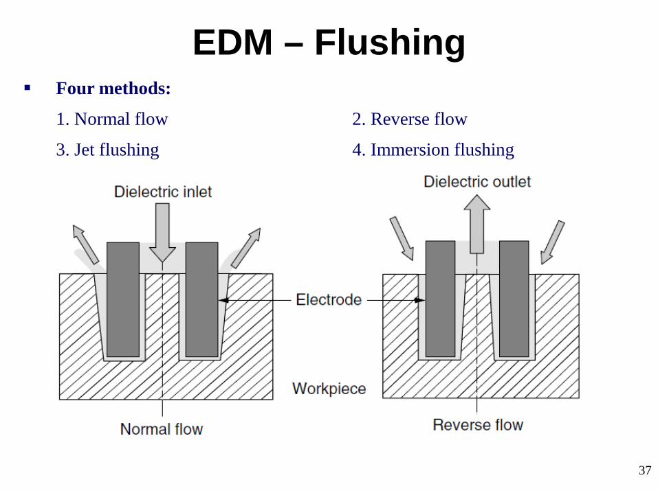
37
EDM – Flushing Four methods:
1. Normal flow 2. Reverse flow
3. Jet flushing 4. Immersion flushing

38
EDM – Flushing Normal flow (Majority)
Dielectric is introduced, under pressure, through one or more passages in the tool and is forced to flow through the gap between tool and work.
Flushing holes are generally placed in areas where the cuts are deepest.
Normal flow is sometimes undesirable because it produces a tapered opening in the workpiece.
Reverse flow
Particularly useful in machining deep cavity dies, where the taper produced using the normal flow mode can be reduced.
The gap is submerged in filtered dielectric, and instead of pressure being applied at the source a vacuum is used.
With clean fluid flowing between the workpiece and the tool, there is no side sparking and, therefore, no taper is produced.

39
EDM – Flushing Jet flushing
In many instances, the desired machining can be achieved by using a spray or jet of fluid directed against the machining gap.
Machining time is always longer with jet flushing than with the normal and reverse flow modes.
Immersion flushing
For many shallow cuts or perforations of thin sections, simple immersion of the discharge gap is sufficient.
Cooling and debris removal can be enhanced during immersion cutting by providing relative motion between the tool and workpiece.
Vibration or cycle interruption comprises periodic reciprocation of the tool relative to the workpiece to effect a pumping action of the dielectric.
40
EDM – Flushing Synchronized, pulsed flushing is also available on some machines.
With this method, flushing occurs only during the non-machining time as the electrode is retracted slightly to enlarge the gap.
Increased electrode life has been reported with this system.
Innovative techniques such as ultrasonic vibrations coupled with mechanical pulse EDM, jet flushing with sweeping nozzles, and electrode pulsing are investigated by Masuzawa (1990).
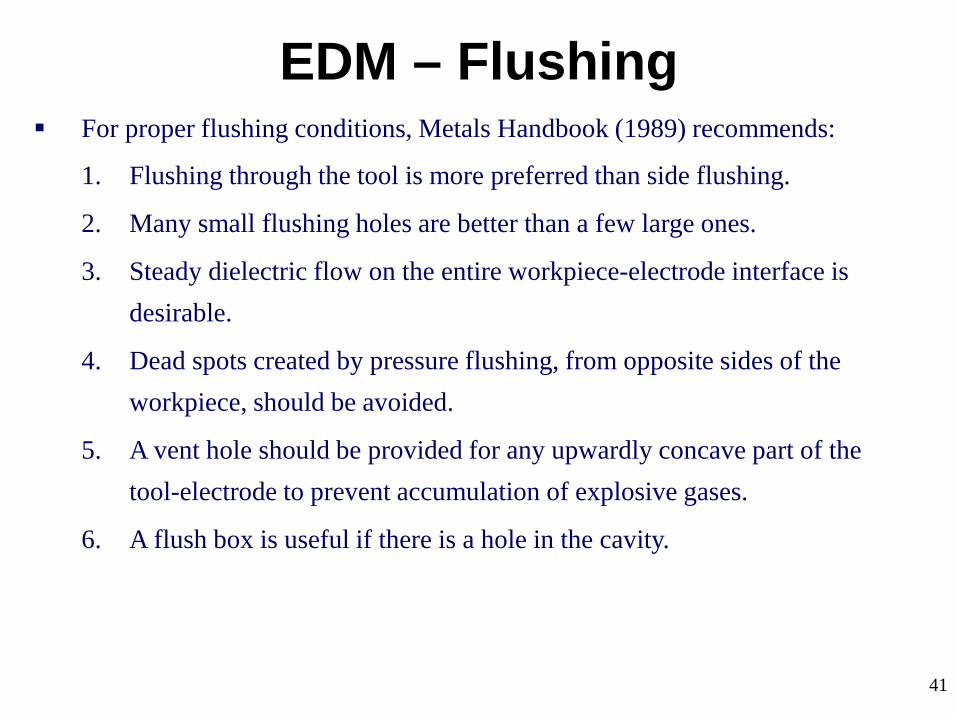
41
EDM – Flushing For proper flushing conditions, Metals Handbook (1989) recommends:
1. Flushing through the tool is more preferred than side flushing.
2. Many small flushing holes are better than a few large ones.
3. Steady dielectric flow on the entire workpiece-electrode interface is desirable.
4. Dead spots created by pressure flushing, from opposite sides of the workpiece, should be avoided.
5. A vent hole should be provided for any upwardly concave part of the tool-electrode to prevent accumulation of explosive gases.
6. A flush box is useful if there is a hole in the cavity.
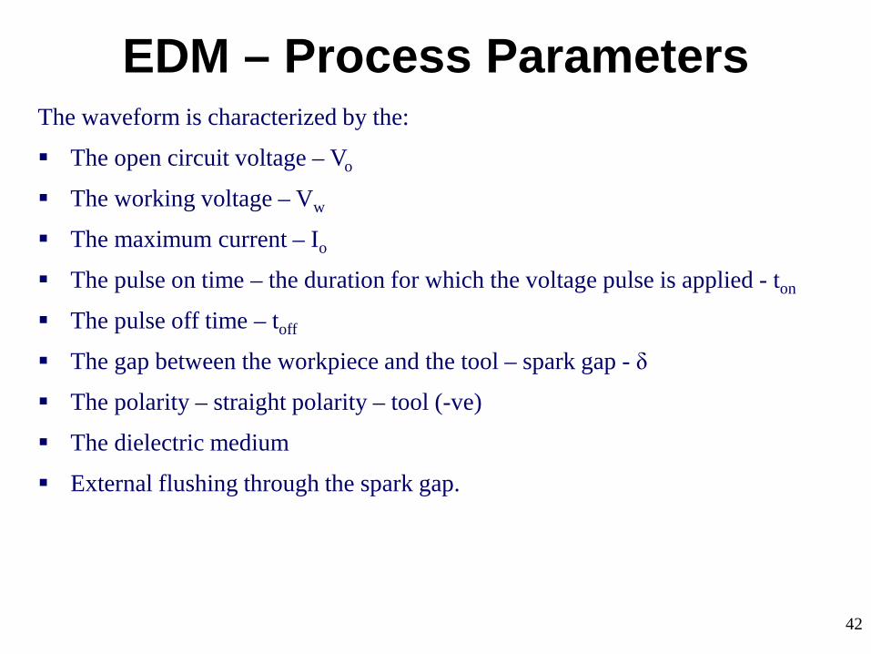
42
EDM – Process Parameters The waveform is characterized by the:
The open circuit voltage – Vo
The working voltage – Vw
The maximum current – Io
The pulse on time – the duration for which the voltage pulse is applied - ton
The pulse off time – toff
The gap between the workpiece and the tool – spark gap - δ
The polarity – straight polarity – tool (-ve)
The dielectric medium
External flushing through the spark gap.

43
The process parameters - mainly related to the waveform characteristics.
EDM – Process Parameters
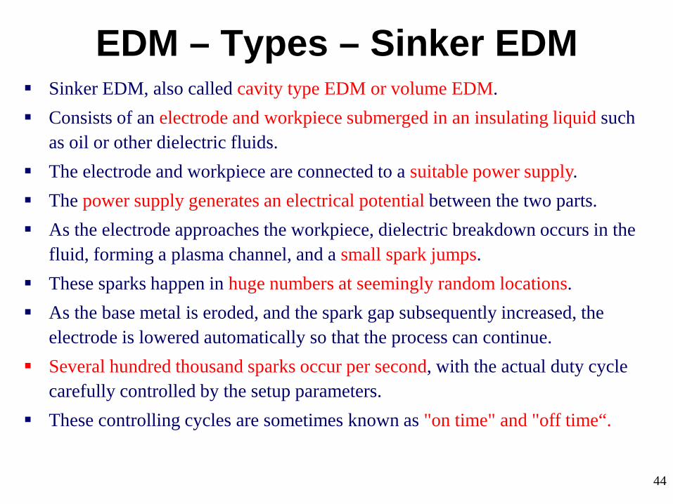
44
EDM – Types – Sinker EDM Sinker EDM, also called cavity type EDM or volume EDM. Consists of an electrode and workpiece submerged in an insulating liquid such
as oil or other dielectric fluids. The electrode and workpiece are connected to a suitable power supply. The power supply generates an electrical potential between the two parts. As the electrode approaches the workpiece, dielectric breakdown occurs in the
fluid, forming a plasma channel, and a small spark jumps. These sparks happen in huge numbers at seemingly random locations. As the base metal is eroded, and the spark gap subsequently increased, the
electrode is lowered automatically so that the process can continue. Several hundred thousand sparks occur per second, with the actual duty cycle
carefully controlled by the setup parameters. These controlling cycles are sometimes known as "on time" and "off time“.

45
EDM – Types – Sinker EDM The on time setting determines the length or duration of the spark.
Hence, a longer on time produces a deeper cavity for that spark and all subsequent sparks for that cycle.
This creates rougher finish on the workpiece.
The reverse is true for a shorter on time.
Off time is the period of time that one spark is replaced by another.
A longer off time, for example, allows the flushing of dielectric fluid through a nozzle to clean out the eroded debris, thereby avoiding a short circuit.
These settings can be maintained in micro seconds.
The typical part geometry is a complex 3D shape, often with small or odd shaped angles.

46
EDM – Types – Wire EDM (WEDM)
Also known as wire-cut EDM and wire cutting.
A thin single-strand metal wire (usually brass) is fed through the workpiece submerged in a tank of dielectric fluid (typically deionized water).
Used to cut plates as thick as 300 mm and to make punches, tools, and dies from hard metals that are difficult to machine with other methods.
Uses water as its dielectric fluid; its resistivity and other electrical properties are controlled with filters and de-ionizer units.
The water flushes the cut debris away from the cutting zone.
Flushing is an important factor in determining the maximum feed rate for a given material thickness.
Commonly used when low residual stresses are desired, because it does not require high cutting forces for material removal.

47
EDM – Material Removal Rate

48
EDM – Material Removal Rate In EDM, the metal is removed from both workpiece and tool electrode.
MRR depends not only on the workpiece material but on the material of the tool electrode and the machining variables such as pulse conditions, electrode polarity, and the machining medium.
In this regard a material of low melting point has a high metal removal rate and hence a rougher surface.
Typical removal rates range from 0.1 to 400 mm3 /min.
MRR or volumetric removal rate (VRR), in mm3/min, was described by Kalpakjian (1997):
where I - EDM current (A)
Tw - Melting point of the workpiece (°C).

49
EDM – Material Removal Rate
Effect of pulse current (energy) on MRR & surface roughness.

50
EDM – Material Removal Rate
Effect of pulse on-time (energy) on MRR & surface roughness.

51
EDM – Surface Integrity Surface consists of a multitude of overlapping craters that are formed by the
action of microsecond-duration spark discharges.
Crater size depends on
physical and mechanical properties of the material
composition of the machining medium
discharge energy and duration.
Integral effect of thousands of discharges per second leads to machining with a specified accuracy and surface finish.
Depth of craters - the peak to valley (maximum) of surface roughness Rt.
Maximum depth of damaged layer can be taken as 2.5 times of roughness Ra.
According to Delpreti (1977) and Motoki and Lee (1968), the maximum peak to valley height, Rt, was considered to be 10 times Ra.

52
EDM – Surface Integrity Average roughness can be expressed in terms of pulse current ip (A) and pulse
duration tp (μs) by
Surface roughness increases linearly with an increase in MRR.
Jeswani (1978) - Graphite electrodes produce rougher surfaces than metal ones.
Kuneida and Furuoya (1991) claimed that the introduction of oxygen into discharge gap provides extra power by the reaction of oxygen.
This in turn increased workpiece melting and created greater expulsive forces that increased MRR and surface roughness.
Choice of correct dielectric flow has a significant effect in reducing surface roughness by 50 %, increasing the machining rate, and lowering the thermal effects in the workpiece surface.
Dielectrics having low viscosity are recommended for smooth surfaces.

53
EDM – Surface Integrity Metallurgical changes occur in the surface – Temperature 8000 to 12,000°C.
Additionally, a thin recast layer of 1 μm to 25 μm – depending on power used.
Delpretti (1977) and Levy and Maggi (1990) claimed that the heat-affected zone (HAZ) adjacent to the resolidified layer reaches 25 μm.
Some annealing can be expected in a zone just below the machined surface.
Not all the workpiece melted by discharge is expelled into the dielectric.
Remaining melted material is quickly chilled, primarily by heat conduction into the bulk of the workpiece, resulting in an exceedingly hard surface.
Depth of annealed layer is proportional to power used.
It ranges from 50 μm for finish cutting to ~ 200 μm for high MRR.
Annealing is usually about two points of hardness below the parent metal for finish cutting.

54
EDM – Surface Integrity In roughing cuts, the annealing effect is ~ five points of hardness below the
parent metal.
Electrodes that produce more stable machining can reduce the annealing effect.
A finish cut removes the annealed material left by the previous rough cut.
The altered surface layer significantly lowers the fatigue strength of alloys.
It consists of a recast layer with or without microcracks, some of which may extend into the base metal, plus metallurgical alterations such as rehardened and tempered layers, heat-affected zones, and inter-granular precipitates.
During EDM roughing, the layer showing microstructural changes, including a melted and resolidified layer, is less than 0.127 mm deep.
During EDM finishing, it is less than 0.075 mm.
Post-treatment to restore the fatigue strength is recommended to follow EDM of critical or highly stressed surfaces.

55
EDM – Surface Integrity There are several effective processes that accomplish restoration or even
enhancement of the fatigue properties.
These methods include
Removal of the altered layers by low-stress grinding or chemical machining
Addition of a metallurgical-type coating
Re heat-treatment
Application of shot peening.

56
EDM – Characteristics Can be used to machine any work material if it is electrically conductive.
MRR depends on thermal properties (job) rather than its strength, hardness etc.
The volume of the material removed per spark discharge is typically in the range of (1/1,000,000) to (1/10,000) mm3.
In EDM, geometry of tool - positive impression of hole or geometric feature.
Tool wear once again depends on the thermal properties of tool material.
Local temperature rise is rather high, but there is not enough heat diffusion (very small pulse on time) and thus HAZ is limited to 2 – 4 μm.
Rapid heating and cooling leads to surface hardening which may be desirable in some applications.
Tolerance value of + 0.05 mm could be easily achieved by EDM.
Best surface finish that can be economically achieved on steel is 0.40 µm.

57
Drilling of micro-holes, thread cutting, helical profile milling, rotary forming, and curved hole drilling.
Delicate work piece like copper parts can be produced by EDM.
Can be applied to all electrically conducting metals and alloys irrespective of their melting points, hardness, toughness, or brittleness.
Other applications: deep, small-dia holes using tungsten wire as tool, narrow slots, cooling holes in super alloy turbine blades, and various intricate shapes.
EDM can be economically employed for extremely hardened work piece.
Since there is no mechanical stress present (no physical contact), fragile and slender work places can be machined without distortion.
Hard and corrosion resistant surfaces, essentially needed for die making, can be developed.
Applications

58
Uses a tubular tool electrode where the dielectric is flushed.
When solid rods are used; dielectric is fed to the machining zone by either suction or injection through pre-drilled holes.
Irregular, tapered, curved, as well as inclined holes can be produced by EDM.
Creating cooling channels in turbine blades made of hard alloys is a typical application of EDM drilling.
Use of NC system enabled large numbers of holes to be accurately located.
Applications – EDM Drilling

59
An EDM variation - Employs either a special steel band or disc.
Cuts at a rate that is twice that of the conventional abrasive sawing method.
Cutting of billets and bars - has a smaller kerf & free from burrs.
Fine finish of 6.3 to 10 μm with a recast layer of 0.025 to 0.130 mm
Applications – EDM Sawing

60
Shichun and coworkers (1995) used simple tubular electrodes in EDM machining of spheres, to a dimensional accuracy of ±1 μm and Ra < 0.1 μm.
Rotary EDM is used for machining of spherical shapes in conducting ceramics using the tool and workpiece arrangement as shown below.
Applications - Machining of spheres

61
EDM milling uses standard cylindrical electrodes.
Simple-shaped electrode (Fig. 1) is rotated at high speeds and follows specified paths in the workpiece like the conventional end mills.
Very useful and makes EDM very versatile like mechanical milling process.
Solves the problem of manufacturing accurate and complex-shaped electrodes for die sinking (Fig. 2) of three-dimensional cavities.
Applications - Machining of dies & molds
(Fig. 2) (Fig. 1)

62
EDM milling enhances dielectric flushing due to high-speed electrode rotation.
Electrode wear can be optimized due to its rotational and contouring motions.
Main limitation in EDM milling - Complex shapes with sharp corners cannot be machined because of the rotating tool electrode.
EDM milling replaces conventional die making that requires variety of machines such as milling, wire cutting, and EDM die sinking machines.
Applications - Machining of dies & molds
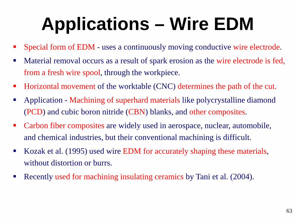
63
Applications – Wire EDM Special form of EDM - uses a continuously moving conductive wire electrode.
Material removal occurs as a result of spark erosion as the wire electrode is fed, from a fresh wire spool, through the workpiece.
Horizontal movement of the worktable (CNC) determines the path of the cut.
Application - Machining of superhard materials like polycrystalline diamond (PCD) and cubic boron nitride (CBN) blanks, and other composites.
Carbon fiber composites are widely used in aerospace, nuclear, automobile, and chemical industries, but their conventional machining is difficult.
Kozak et al. (1995) used wire EDM for accurately shaping these materials, without distortion or burrs.
Recently used for machining insulating ceramics by Tani et al. (2004).

64
Applications – Wire EDM
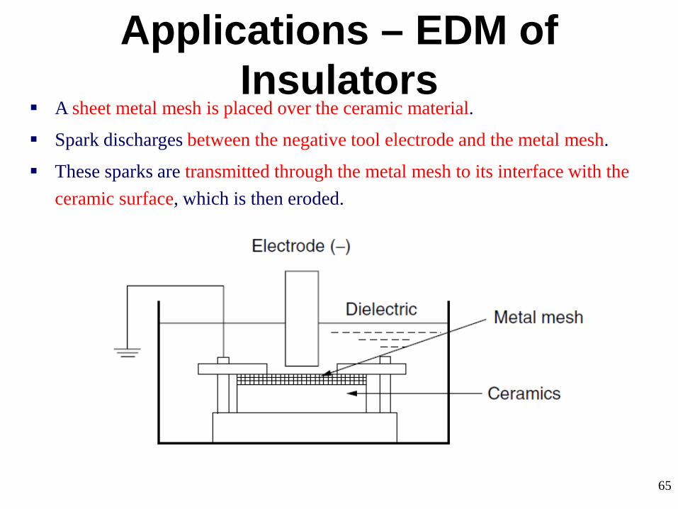
65
Applications – EDM of Insulators
A sheet metal mesh is placed over the ceramic material.
Spark discharges between the negative tool electrode and the metal mesh.
These sparks are transmitted through the metal mesh to its interface with the ceramic surface, which is then eroded.

66
Applications – Texturing Texturing is applied to steel sheets during the final stages of cold rolling.
Shot blasting (SB) is an inexpensive method of texturing.
Limitations of SB include its lack of control and consistency of texturing, and the need for protection of other parts of the equipment holding the roll.
EDT, is a variation of EDM and proved to be the most popular.
Texturing is achieved by producing electrical sparks across the gap between roll (workpiece) and a tool electrode, in the presence of dielectric (paraffin).
Each spark creates a small crater by the discharge of its energy in a local melting and vaporization of the roll material.
By selecting the appropriate process variables such as pulse current, on and off time, electrode polarity, dielectric type, and the roll rotational speed, a surface texture with a high degree of accuracy and consistency can be produced.
67
Some of the advantages of EDM include machining of:
Complex shapes that would otherwise be difficult to produce with conventional cutting tools.
Extremely hard material to very close tolerances.
Very small work pieces where conventional cutting tools may damage the part from excess cutting tool pressure.
There is no direct contact between tool and work piece. Therefore delicate sections and weak materials can be machined without any distortion.
A good surface finish can be obtained.
Advantages

68
Some of the disadvantages of EDM include:
The slow rate of material removal.
For economic production, the surface finish specified should not be too fine.
The additional time and cost used for creating electrodes for ram/sinker EDM.
Reproducing sharp corners on the workpiece is difficult due to electrode wear.
Specific power consumption is very high.
Power consumption is high.
"Overcut" is formed.
Excessive tool wear occurs during machining.
Electrically non-conductive materials can be machined only with specific set-up of the process
Disadvantages
Related Documents