ELEC1041 - Combinational Logic Examples - 1 Digital Electronics Tutorial: Combinational Logic Design Examples Solutions

ELEC1041 - Combinational Logic Examples - 1 Digital Electronics Tutorial: Combinational Logic Design Examples Solutions.
Dec 28, 2015
Welcome message from author
This document is posted to help you gain knowledge. Please leave a comment to let me know what you think about it! Share it to your friends and learn new things together.
Transcript
ELEC1041 - Combinational Logic Examples - 1
Digital Electronics
Tutorial: Combinational Logic Design Examples
Solutions
ELEC1041 - Combinational Logic Examples - 2
Problem #1
Develop a minimized Boolean implementation of a “ones count” circuit that works as follows. The subsystem has four binary inputs A, B, C, D, and generates a 3-bit output, XYZ. XYZ is 000 if none of the inputs are 1, 001 if one input is 1, 010 if two are one, 011 if three inputs are 1, and 100 if all four inputs are 1.
(a) Draw the truth tables for XYZ (A, B, C, D).
(b) Minimize the functions X, Y, Z using 4-variable K-maps. Write down the Boolean expressions for the minimized Sum of Products form of each function.
(c) Repeat the minimization process, this time deriving Product of Sums form.
ELEC1041 - Combinational Logic Examples - 3
Problem #1 Solution (1/6)
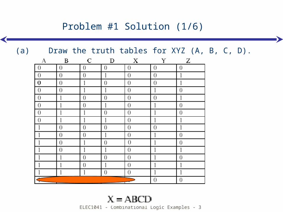
(a) Draw the truth tables for XYZ (A, B, C, D).
ELEC1041 - Combinational Logic Examples - 4
Problem #1 Solution (2/6)
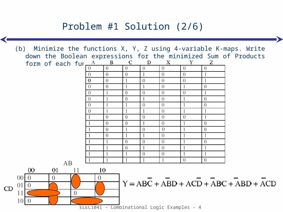
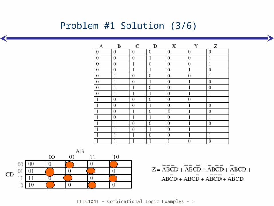
(b) Minimize the functions X, Y, Z using 4-variable K-maps. Write down the Boolean expressions for the minimized Sum of Products form of each function.
ELEC1041 - Combinational Logic Examples - 5
Problem #1 Solution (3/6)
ELEC1041 - Combinational Logic Examples - 6
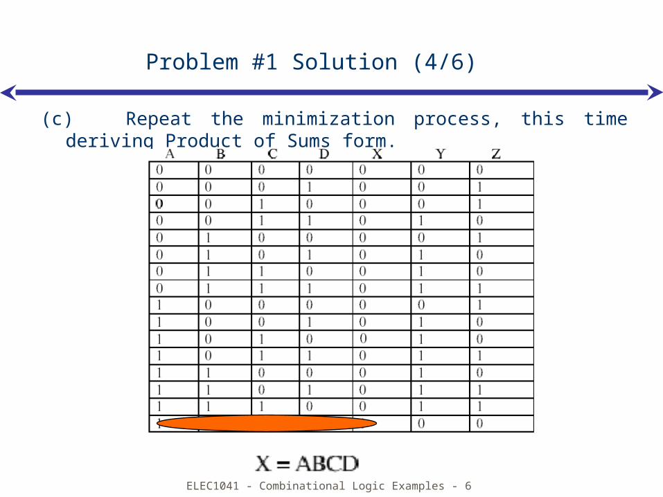
Problem #1 Solution (4/6)
(c) Repeat the minimization process, this time deriving Product of Sums form.
ELEC1041 - Combinational Logic Examples - 7
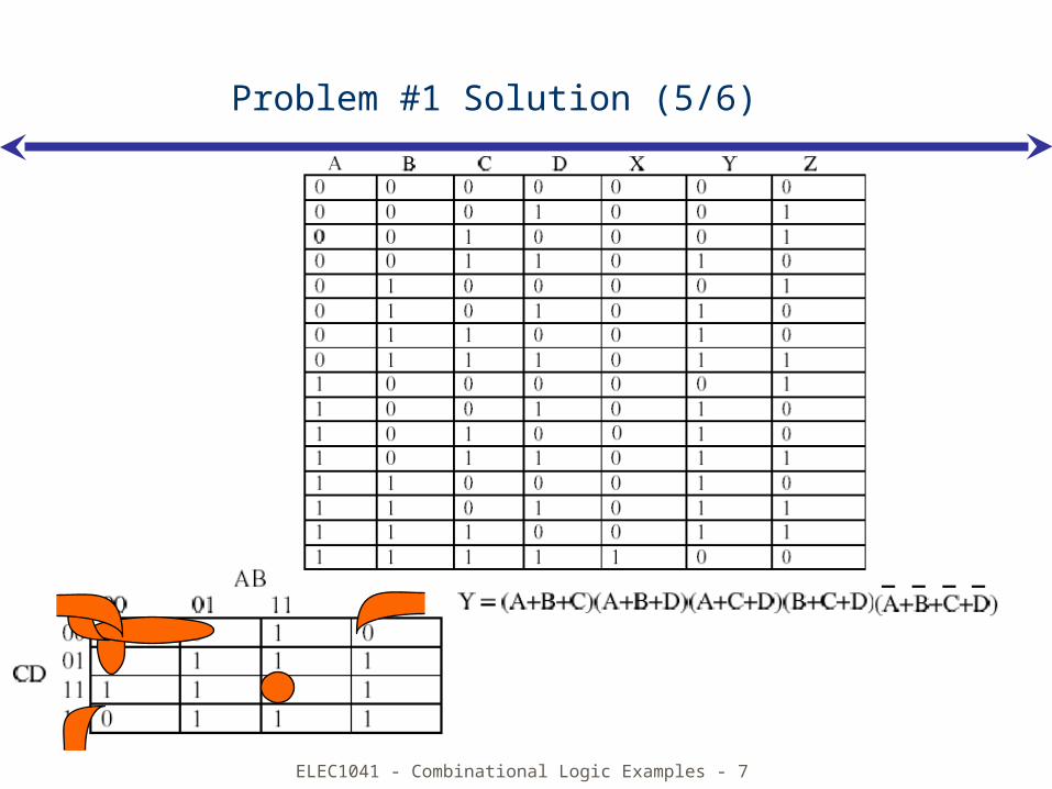
Problem #1 Solution (5/6)
ELEC1041 - Combinational Logic Examples - 8
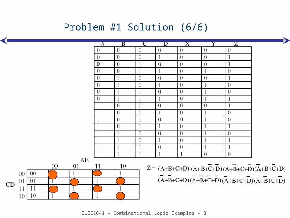
Problem #1 Solution (6/6)
ELEC1041 - Combinational Logic Examples - 9
Problem #2
Consider a combinational logic subsystem that performs a two-bit addition function. It has two 2-bit inputs A B and C D, and forms the 3-bit sum X Y Z.
(a) Draw the truth tables for XYZ(A,B,C,D).
(b) Minimize the functions using 4-variable K-maps to derive minimized Sum of Products forms.
(c) In your textbook and in class/lab we have introduced the Full Adder circuit. What is the relative performance to compute the resulting sum bits of the 2-bit adder compared to two full adders connected together? (Hint: which has the worst delay in terms of gates to pass through between the inputs and the final outputs, and how many gates is this?).
ELEC1041 - Combinational Logic Examples - 10
Problem #2 Solution (1/3)
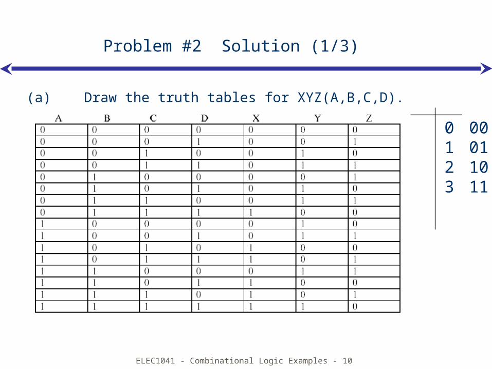
(a) Draw the truth tables for XYZ(A,B,C,D).
0 001 012 103 11
ELEC1041 - Combinational Logic Examples - 11
Problem #2 Solution (2/3)
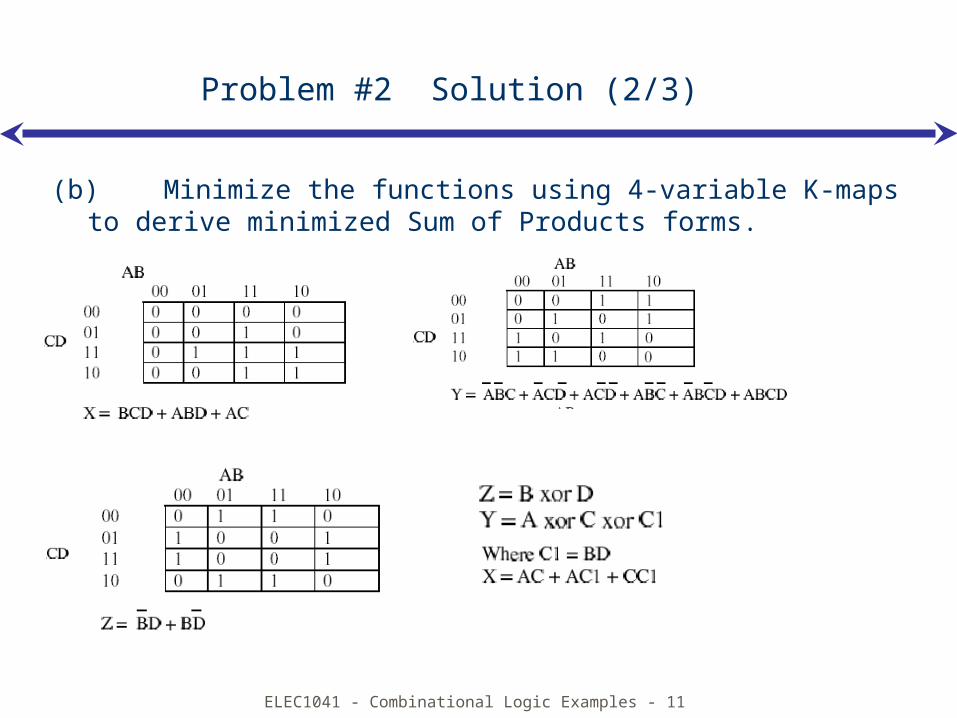
(b) Minimize the functions using 4-variable K-maps to derive minimized Sum of Products forms.
ELEC1041 - Combinational Logic Examples - 12
Problem #2 Solution (3/3)
(c) In your textbook and in class/lab we have introduced the Full Adder circuit. What is the relative performance to compute the resulting sum bits of the 2-bit adder compared to two full adders connected together? (Hint: which has the worst delay in terms of gates to pass through between the inputs and the final outputs, and how many gates is this?).
The above circuit is better because there are only two gate levels. But the adder circuit can be used to build adder circuit of more bits. I can’t imagine doing a K-map to construct a adder circuit of 64 bits using the method above.
ELEC1041 - Combinational Logic Examples - 13
Problem #3
Show how to implement the full adder Sum(A, B, Cin) and Carry(A, B, Cin) in terms of:
(a) Two 8:1 multiplexers;
(b) Two 4:1 multiplexers;
(c) If you are limited to 2:1 multiplexers (and inverters) only, how would you use them to implement the full adder and how many 2:1 multiplexers would you need?
ELEC1041 - Combinational Logic Examples - 14
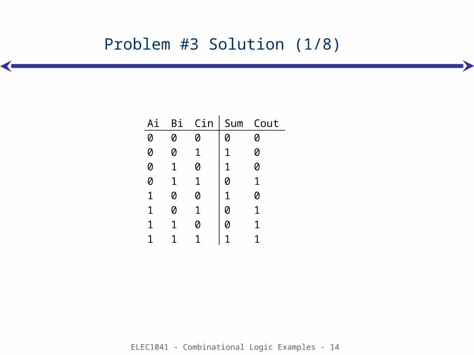
Problem #3 Solution (1/8)
Ai Bi Cin Sum Cout0 0 0 0 00 0 1 1 00 1 0 1 00 1 1 0 11 0 0 1 01 0 1 0 11 1 0 0 11 1 1 1 1
ELEC1041 - Combinational Logic Examples - 15
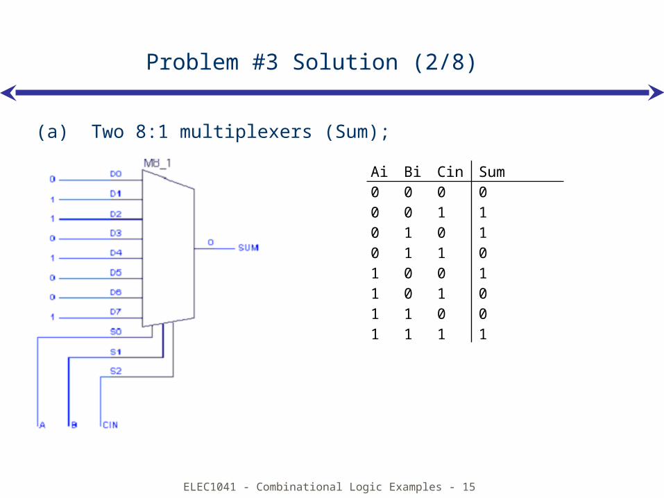
Problem #3 Solution (2/8)
(a) Two 8:1 multiplexers (Sum);
Ai Bi Cin Sum0 0 0 00 0 1 10 1 0 10 1 1 01 0 0 11 0 1 01 1 0 01 1 1 1
ELEC1041 - Combinational Logic Examples - 16
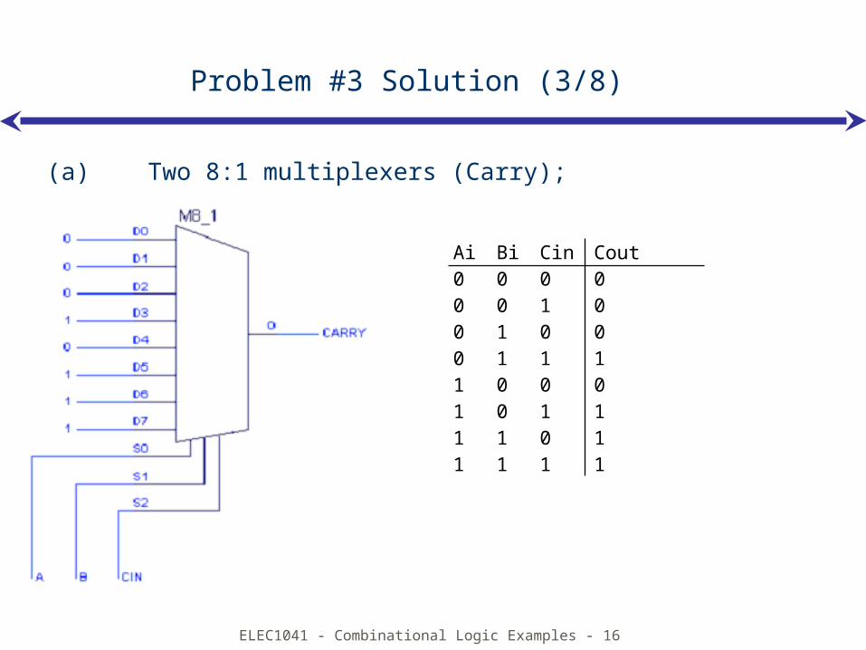
Problem #3 Solution (3/8)
(a) Two 8:1 multiplexers (Carry);
Ai Bi Cin Cout0 0 0 00 0 1 00 1 0 00 1 1 11 0 0 01 0 1 11 1 0 11 1 1 1
ELEC1041 - Combinational Logic Examples - 17
Problem #3 Solution (4/8)
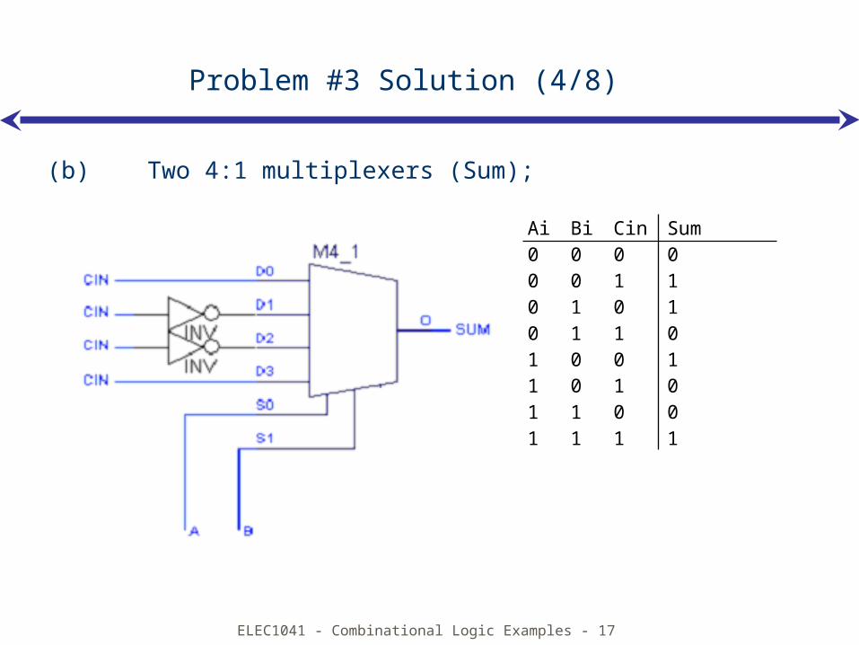
(b) Two 4:1 multiplexers (Sum);
Ai Bi Cin Sum0 0 0 00 0 1 10 1 0 10 1 1 01 0 0 11 0 1 01 1 0 01 1 1 1
ELEC1041 - Combinational Logic Examples - 18
Problem #3 Solution (5/8)
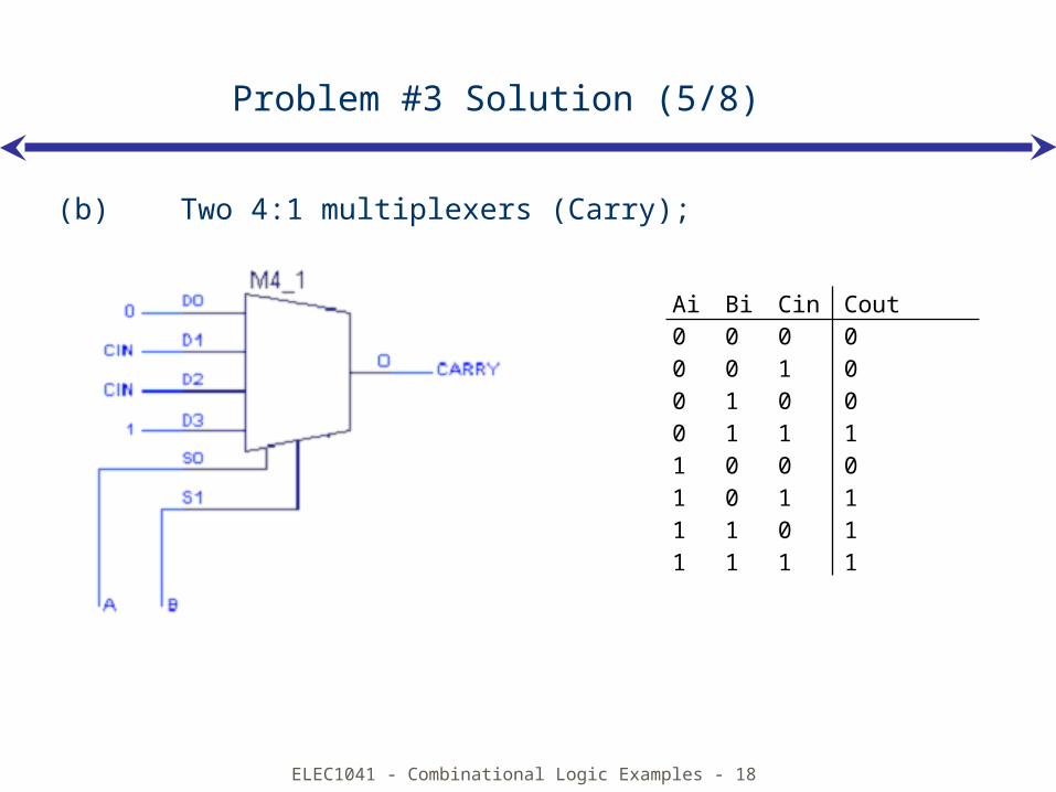
(b) Two 4:1 multiplexers (Carry);
Ai Bi Cin Cout0 0 0 00 0 1 00 1 0 00 1 1 11 0 0 01 0 1 11 1 0 11 1 1 1

ELEC1041 - Combinational Logic Examples - 19
Problem #3 Solution (6/8)
(c) 2:1 multiplexers (sum)
Ai Bi Cin Sum0 0 0 00 0 1 10 1 0 10 1 1 01 0 0 11 0 1 01 1 0 01 1 1 1
ELEC1041 - Combinational Logic Examples - 20
Problem #3 Solution (7/8)
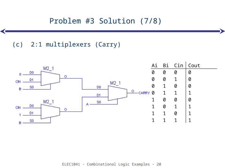
(c) 2:1 multiplexers (Carry)
Ai Bi Cin Cout0 0 0 00 0 1 00 1 0 00 1 1 11 0 0 01 0 1 11 1 0 11 1 1 1
ELEC1041 - Combinational Logic Examples - 21
Problem #3 Solution (8/8)
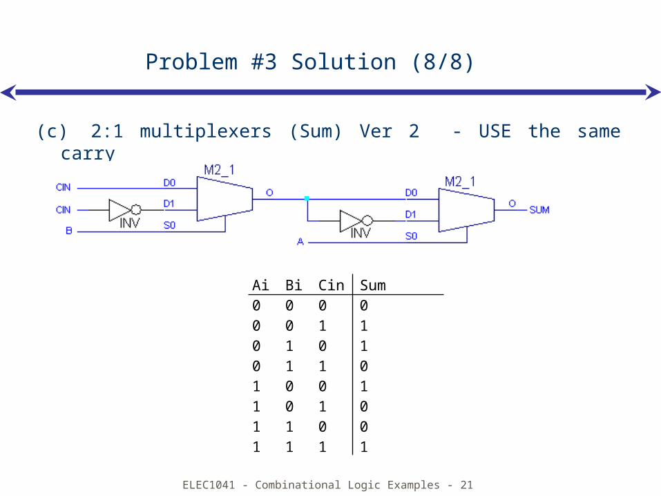
(c) 2:1 multiplexers (Sum) Ver 2 - USE the same carry
Ai Bi Cin Sum0 0 0 00 0 1 10 1 0 10 1 1 01 0 0 11 0 1 01 1 0 01 1 1 1
ELEC1041 - Combinational Logic Examples - 22
Problem #4
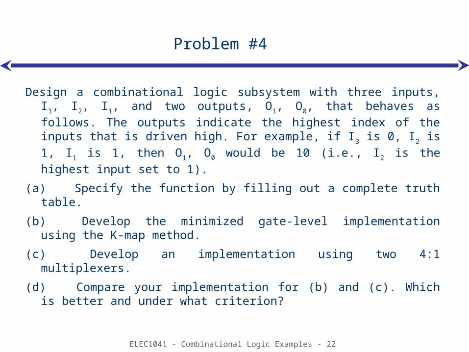
Design a combinational logic subsystem with three inputs, I3, I2, I1, and two outputs, O1, O0, that behaves as follows. The outputs indicate the highest index of the inputs that is driven high. For example, if I3 is 0, I2 is 1, I1 is 1, then O1, O0 would be 10 (i.e., I2 is the highest input set to 1).
(a) Specify the function by filling out a complete truth table.
(b) Develop the minimized gate-level implementation using the K-map method.
(c) Develop an implementation using two 4:1 multiplexers.
(d) Compare your implementation for (b) and (c). Which is better and under what criterion?
ELEC1041 - Combinational Logic Examples - 23
Problem #4 Solution (1/5)
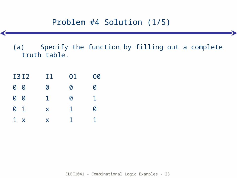
(a) Specify the function by filling out a complete truth table.
I3 I2 I1 O1 O0
0 0 0 0 0
0 0 1 0 1
0 1 x 1 0
1 x x 1 1
ELEC1041 - Combinational Logic Examples - 24
Problem #4 Solution (2/5)
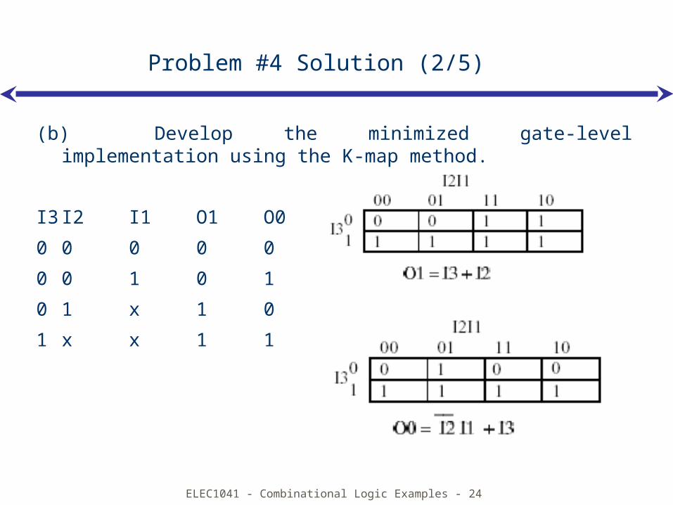
(b) Develop the minimized gate-level implementation using the K-map method.
I3 I2 I1 O1 O0
0 0 0 0 0
0 0 1 0 1
0 1 x 1 0
1 x x 1 1
ELEC1041 - Combinational Logic Examples - 25
Problem #4 Solution (3/5)
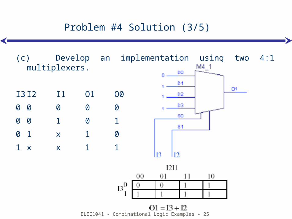
(c) Develop an implementation using two 4:1 multiplexers.
I3 I2 I1 O1 O0
0 0 0 0 0
0 0 1 0 1
0 1 x 1 0
1 x x 1 1
ELEC1041 - Combinational Logic Examples - 26
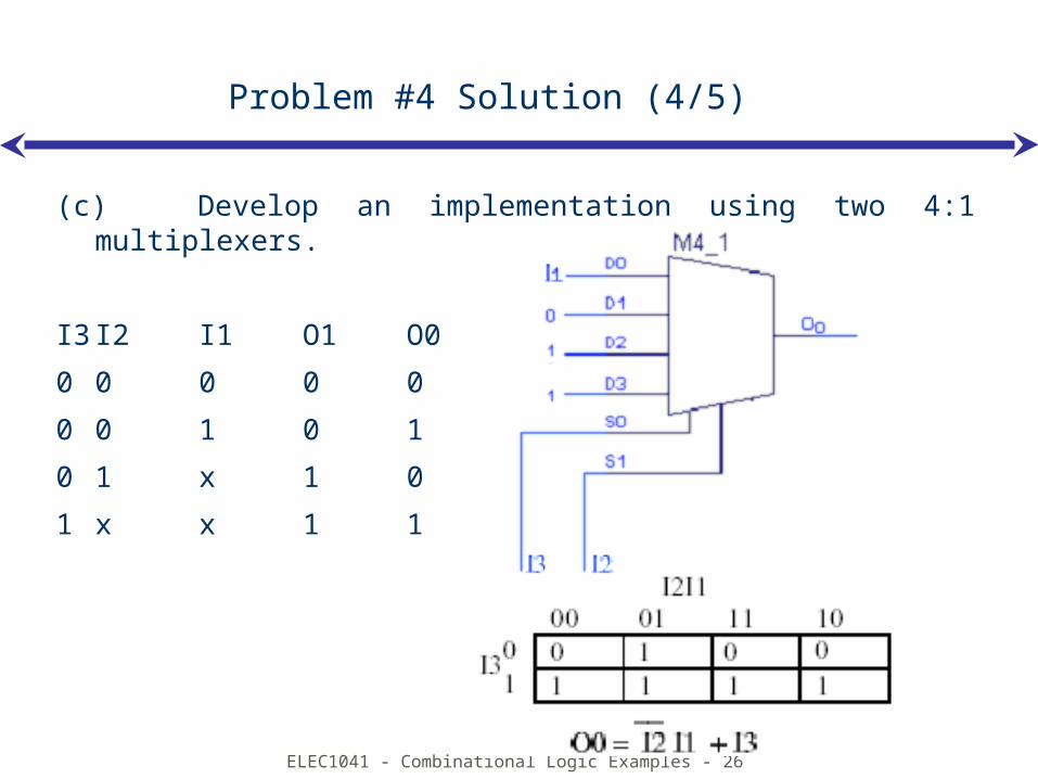
Problem #4 Solution (4/5)
(c) Develop an implementation using two 4:1 multiplexers.
I3 I2 I1 O1 O0
0 0 0 0 0
0 0 1 0 1
0 1 x 1 0
1 x x 1 1
ELEC1041 - Combinational Logic Examples - 27
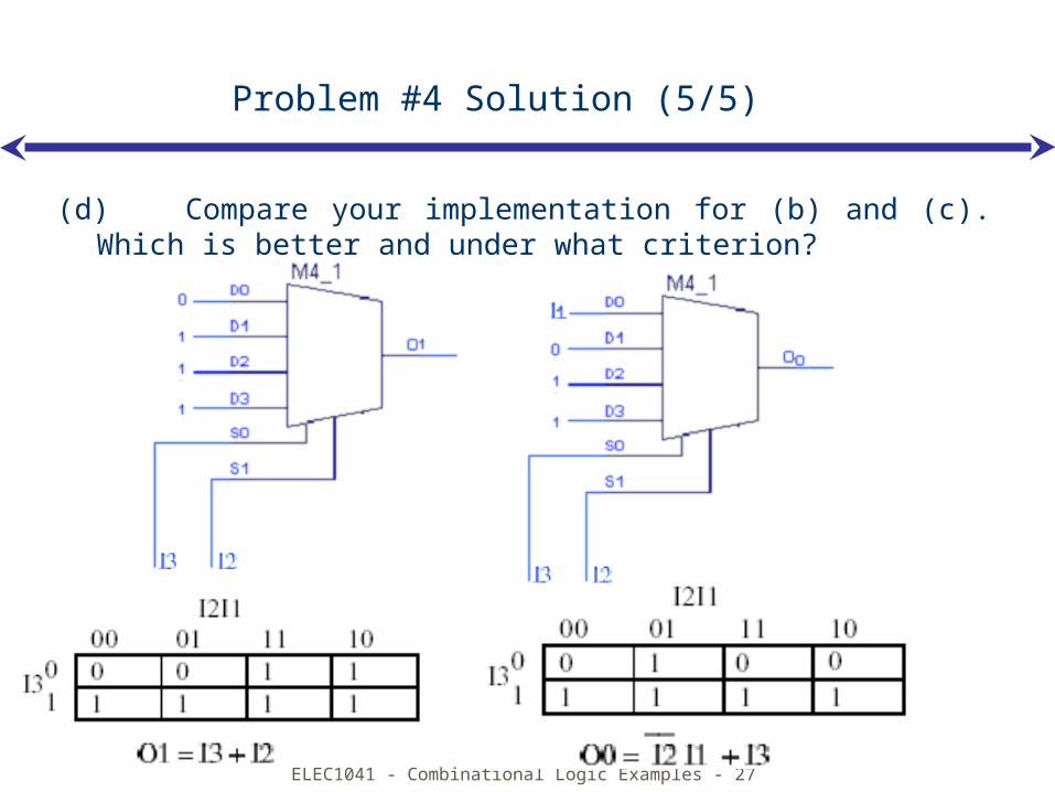
Problem #4 Solution (5/5)
(d) Compare your implementation for (b) and (c). Which is better and under what criterion?
ELEC1041 - Combinational Logic Examples - 28
Problem #5
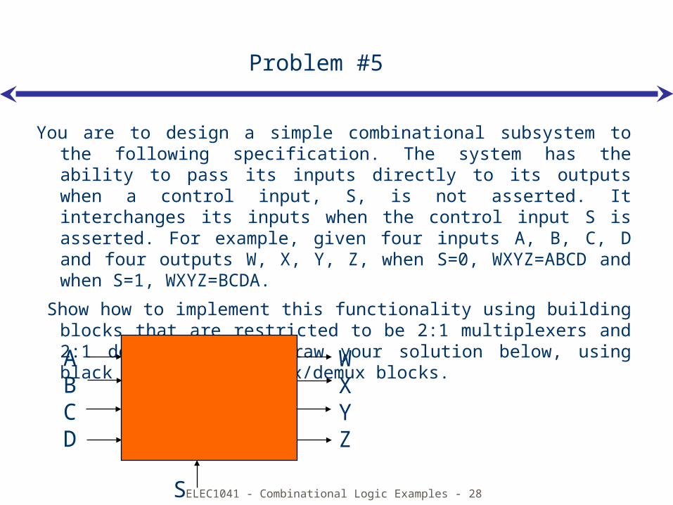
You are to design a simple combinational subsystem to the following specification. The system has the ability to pass its inputs directly to its outputs when a control input, S, is not asserted. It interchanges its inputs when the control input S is asserted. For example, given four inputs A, B, C, D and four outputs W, X, Y, Z, when S=0, WXYZ=ABCD and when S=1, WXYZ=BCDA.
Show how to implement this functionality using building blocks that are restricted to be 2:1 multiplexers and 2:1 demultiplexers. Draw your solution below, using black boxes for the mux/demux blocks.
ABCD
WXYZ
S
ELEC1041 - Combinational Logic Examples - 29
Problem #5 Solution
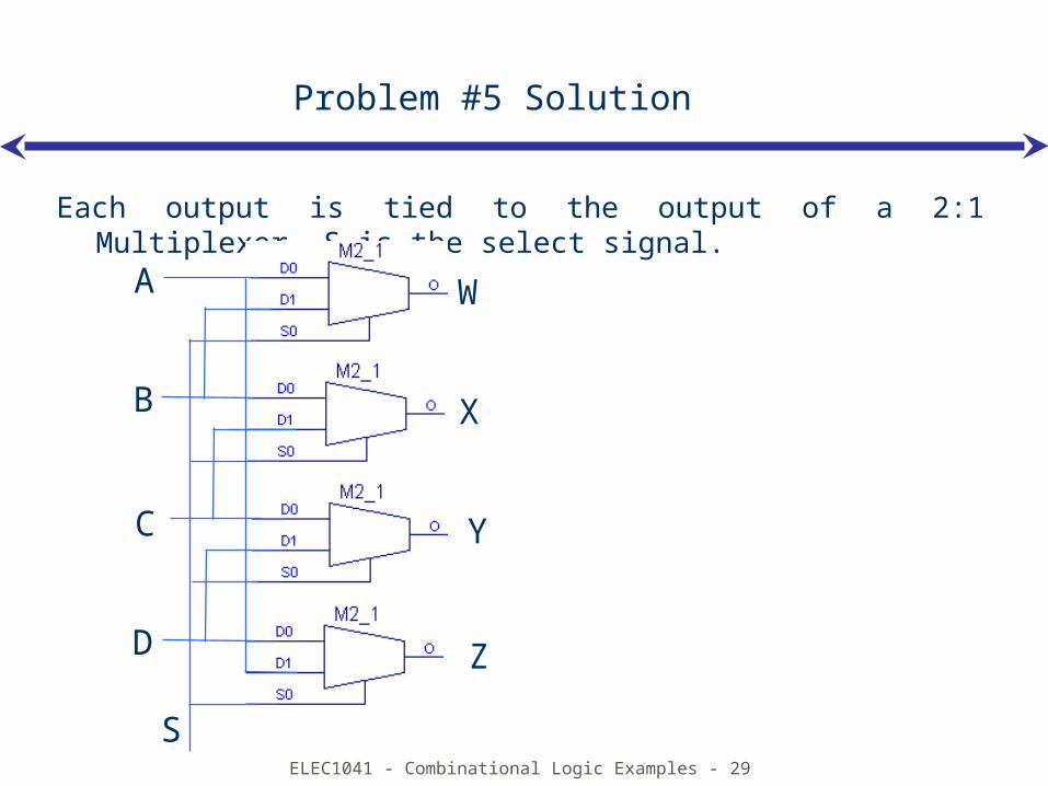
Each output is tied to the output of a 2:1 Multiplexer. S is the select signal.
S
A W
B X
C
D
Y
Z
ELEC1041 - Combinational Logic Examples - 30
Problem #6
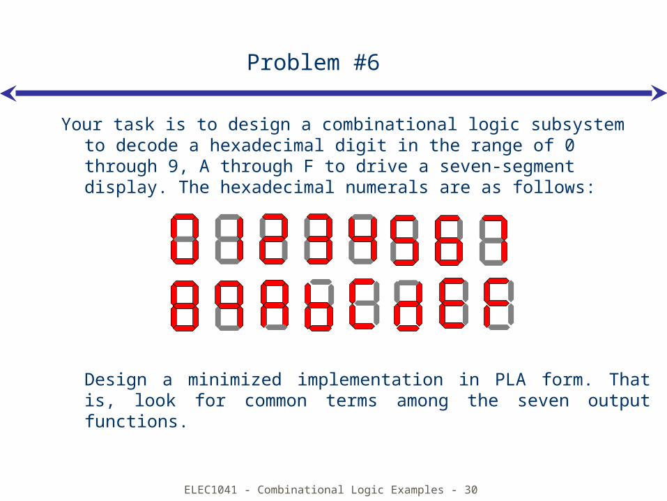
Your task is to design a combinational logic subsystem to decode a hexadecimal digit in the range of 0 through 9, A through F to drive a seven-segment display. The hexadecimal numerals are as follows:
Design a minimized implementation in PLA form. That is, look for common terms among the seven output functions.
ELEC1041 - Combinational Logic Examples - 31
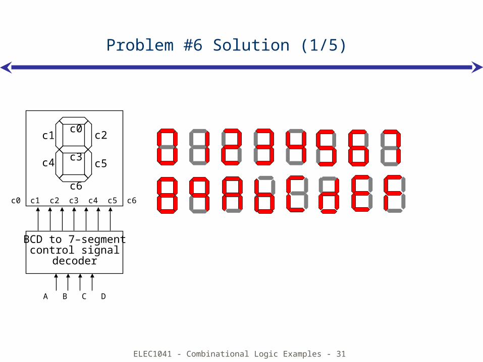
Problem #6 Solution (1/5)
BCD to 7–segmentcontrol signal
decoder
c0 c1 c2 c3 c4 c5 c6
A B C D
c2c1
c5c4 c3
c0
c6
ELEC1041 - Combinational Logic Examples - 32
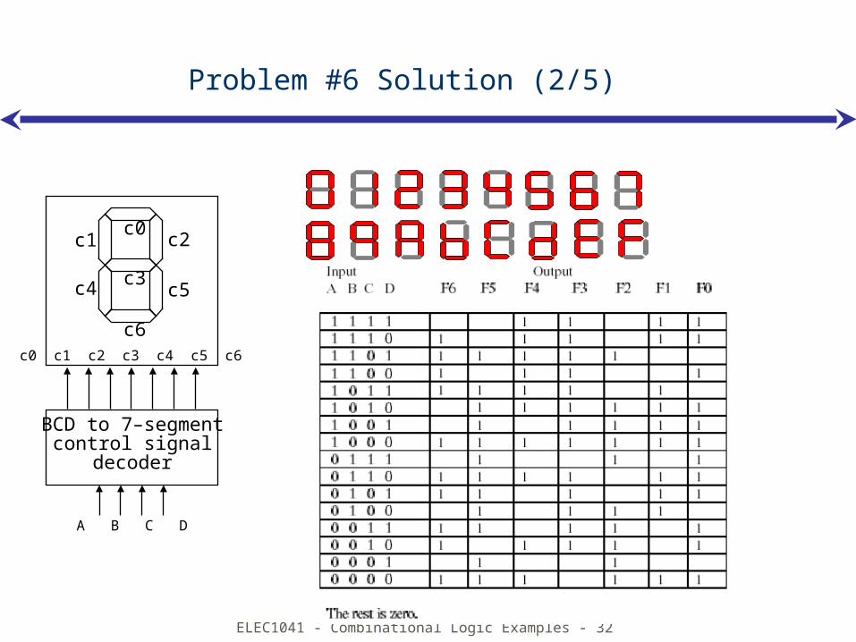
Problem #6 Solution (2/5)
BCD to 7–segmentcontrol signal
decoder
c0 c1 c2 c3 c4 c5 c6
A B C D
c2c1
c5c4 c3
c0
c6
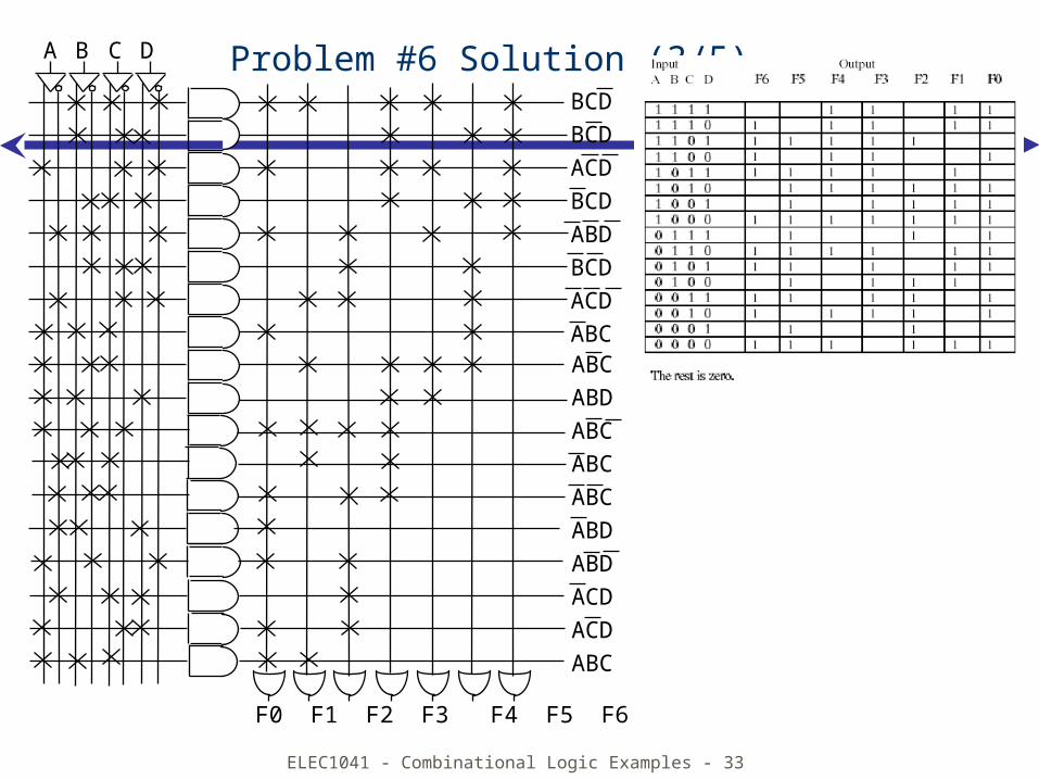
ELEC1041 - Combinational Logic Examples - 33
Problem #6 Solution (3/5)BCDBCDACDBCDABDBCDACDABC
A B C D
F0 F1 F2 F3 F4 F5 F6
ABCABDABCABCABCABDABDACD ACDABC
ELEC1041 - Combinational Logic Examples - 34
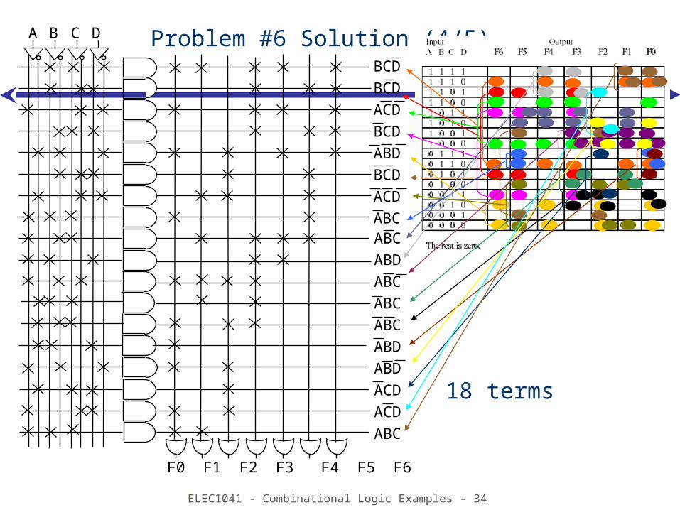
Problem #6 Solution (4/5)BCDBCDACDBCDABDBCDACDABC
A B C D
F0 F1 F2 F3 F4 F5 F6
ABCABDABCABCABCABDABDACD ACDABC
18 terms
ELEC1041 - Combinational Logic Examples - 35
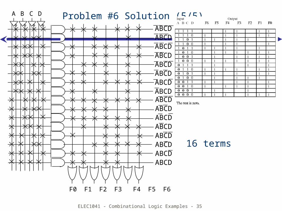
Problem #6 Solution (5/5)ABCDABCDABCDABCDABCDABCDABCDABCD
A B C D
F0 F1 F2 F3 F4 F5 F6
ABCDABCDABCDABCDABCDABCDABCDABCD
16 terms
ELEC1041 - Combinational Logic Examples - 36
Problem #7
Calendar subsystem
Determine number of days in a month (to control watch display)used in controlling the display of a wrist-watch LCD screen
inputs: month, leap year flagoutputs: number of days
ELEC1041 - Combinational Logic Examples - 37
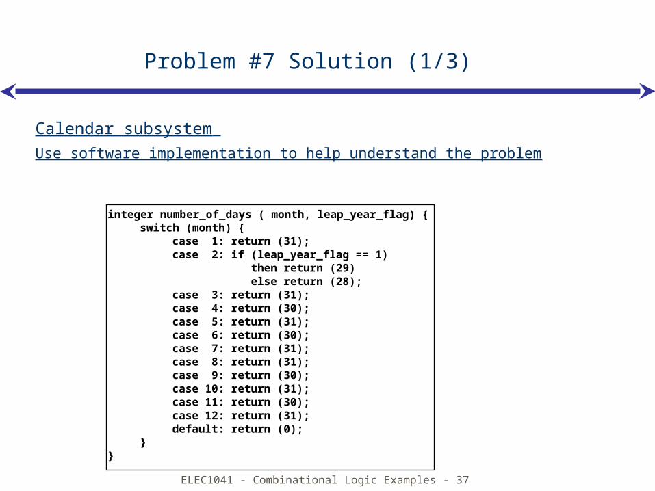
integer number_of_days ( month, leap_year_flag) {switch (month) {
case 1: return (31);case 2: if (leap_year_flag == 1) then return (29) else return (28);case 3: return (31);case 4: return (30);case 5: return (31);case 6: return (30);case 7: return (31);case 8: return (31);case 9: return (30);case 10: return (31);case 11: return (30);case 12: return (31);default: return (0);
}}
Problem #7 Solution (1/3)
Calendar subsystem
Use software implementation to help understand the problem
ELEC1041 - Combinational Logic Examples - 38
leapmonth
28 29 30 31
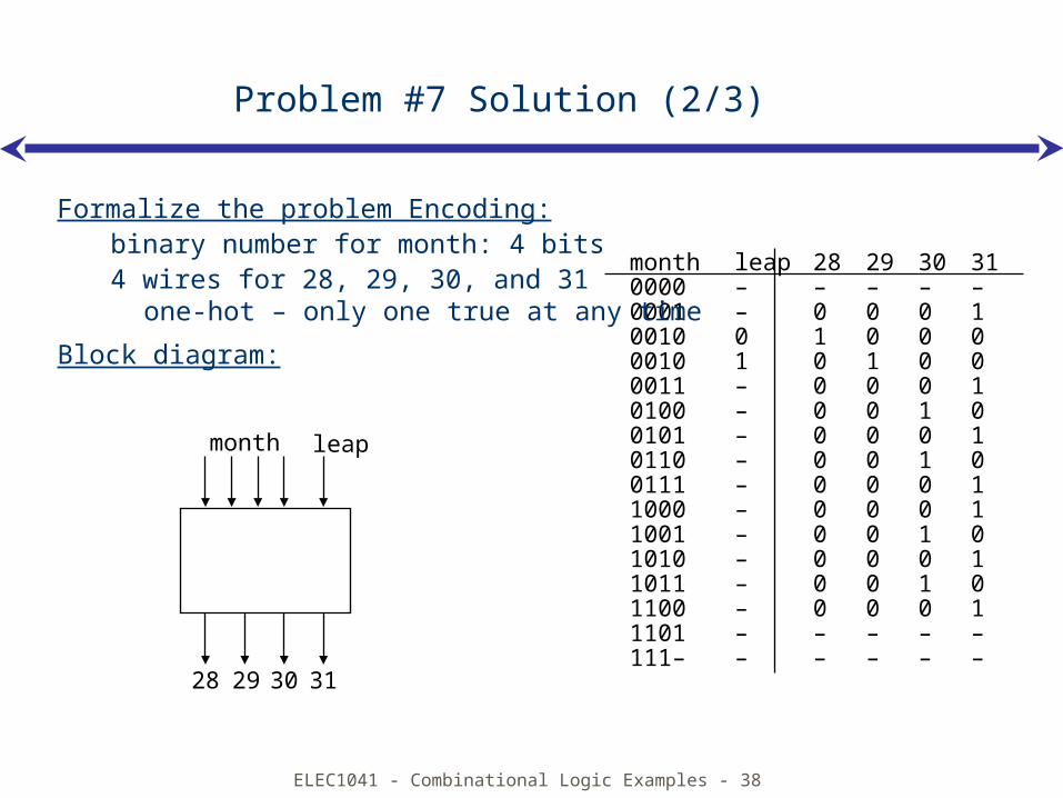
month leap 28 29 30 310000 – – – – –0001 – 0 0 0 10010 0 1 0 0 00010 1 0 1 0 00011 – 0 0 0 10100 – 0 0 1 00101 – 0 0 0 10110 – 0 0 1 00111 – 0 0 0 11000 – 0 0 0 11001 – 0 0 1 01010 – 0 0 0 11011 – 0 0 1 01100 – 0 0 0 11101 – – – – –111– – – – – –
Problem #7 Solution (2/3)
Formalize the problem Encoding:binary number for month: 4 bits4 wires for 28, 29, 30, and 31
one-hot – only one true at any time
Block diagram:
ELEC1041 - Combinational Logic Examples - 39
month leap 28 29 30 310000 – – – – –0001 – 0 0 0 10010 0 1 0 0 00010 1 0 1 0 00011 – 0 0 0 10100 – 0 0 1 00101 – 0 0 0 10110 – 0 0 1 00111 – 0 0 0 11000 – 0 0 0 11001 – 0 0 1 01010 – 0 0 0 11011 – 0 0 1 01100 – 0 0 0 11101 – – – – –111– – – – – –
Problem #7 Solution (3/3)
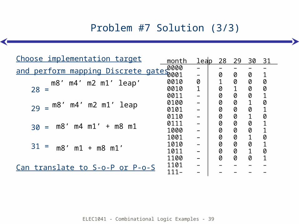
Choose implementation target
and perform mapping Discrete gates
28 =
29 =
30 =
31 =
Can translate to S-o-P or P-o-S
m8’ m4’ m2 m1’ leap’
m8’ m4’ m2 m1’ leap
m8’ m4 m1’ + m8 m1
m8’ m1 + m8 m1’
ELEC1041 - Combinational Logic Examples - 40
Problem #8
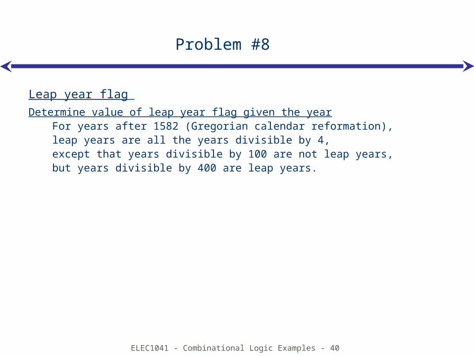
Leap year flag
Determine value of leap year flag given the yearFor years after 1582 (Gregorian calendar reformation), leap years are all the years divisible by 4, except that years divisible by 100 are not leap years, but years divisible by 400 are leap years.

ELEC1041 - Combinational Logic Examples - 41
Problem #8 Solution (1/5)
Leap year flag
Encoding the year:binary – easy for divisible by 4, but difficult for 100 and 400 (not powers
of 2)BCD – easy for 100, but more difficult for 4, what about 400?
Parts:construct a circuit that determines if the year is divisible by 4construct a circuit that determines if the year is divisible by 100construct a circuit that determines if the year is divisible by 400combine the results of the previous three steps to yield the leap year flag
ELEC1041 - Combinational Logic Examples - 42
Problem #8 Solution (2/5)
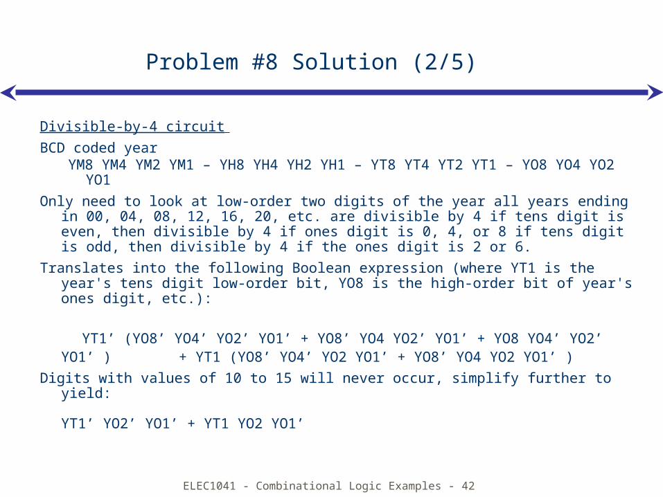
Divisible-by-4 circuit
BCD coded year YM8 YM4 YM2 YM1 – YH8 YH4 YH2 YH1 – YT8 YT4 YT2 YT1 – YO8 YO4
YO2 YO1
Only need to look at low-order two digits of the year all years ending in 00, 04, 08, 12, 16, 20, etc. are divisible by 4 if tens digit is even, then divisible by 4 if ones digit is 0, 4, or 8 if tens digit is odd, then divisible by 4 if the ones digit is 2 or 6.
Translates into the following Boolean expression (where YT1 is the year's tens digit low-order bit, YO8 is the high-order bit of year's ones digit, etc.):
YT1’ (YO8’ YO4’ YO2’ YO1’ + YO8’ YO4 YO2’ YO1’ + YO8 YO4’ YO2’ YO1’ ) + YT1 (YO8’ YO4’ YO2 YO1’ + YO8’ YO4 YO2 YO1’ )
Digits with values of 10 to 15 will never occur, simplify further to yield:
YT1’ YO2’ YO1’ + YT1 YO2 YO1’
ELEC1041 - Combinational Logic Examples - 43
Problem #8 Solution (3/5)
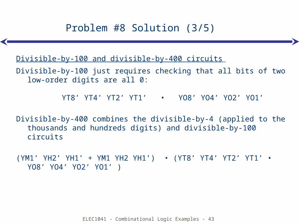
Divisible-by-100 and divisible-by-400 circuits
Divisible-by-100 just requires checking that all bits of two low-order digits are all 0:
YT8’ YT4’ YT2’ YT1’ • YO8’ YO4’ YO2’ YO1’
Divisible-by-400 combines the divisible-by-4 (applied to the thousands and hundreds digits) and divisible-by-100 circuits
(YM1’ YH2’ YH1’ + YM1 YH2 YH1’) • (YT8’ YT4’ YT2’ YT1’ • YO8’ YO4’ YO2’ YO1’ )
ELEC1041 - Combinational Logic Examples - 44
Problem #8 Solution (4/5)
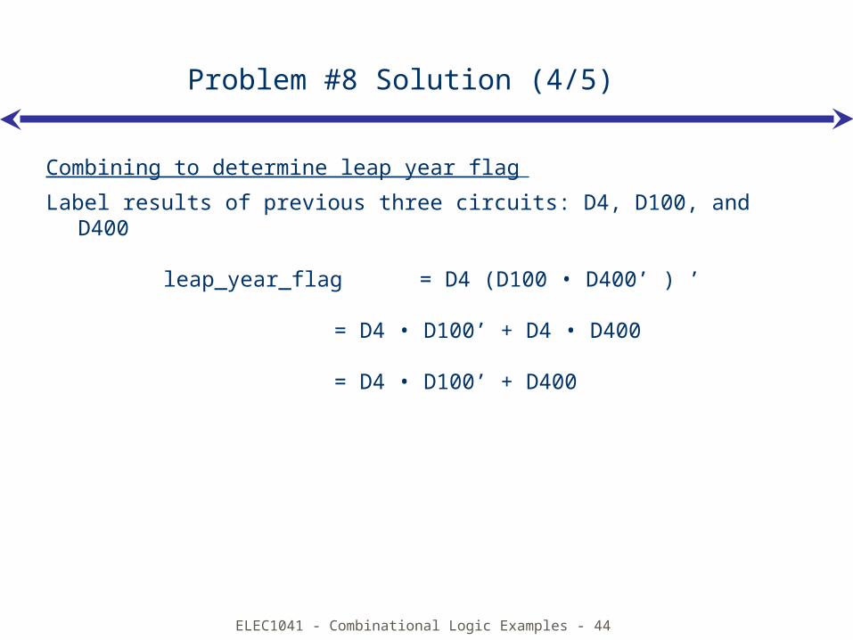
Combining to determine leap year flag
Label results of previous three circuits: D4, D100, and D400
leap_year_flag = D4 (D100 • D400’ ) ’
= D4 • D100’ + D4 • D400
= D4 • D100’ + D400
ELEC1041 - Combinational Logic Examples - 45
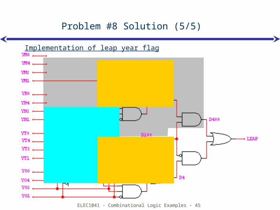
Problem #8 Solution (5/5)
Implementation of leap year flag
ELEC1041 - Combinational Logic Examples - 46
Problem #9
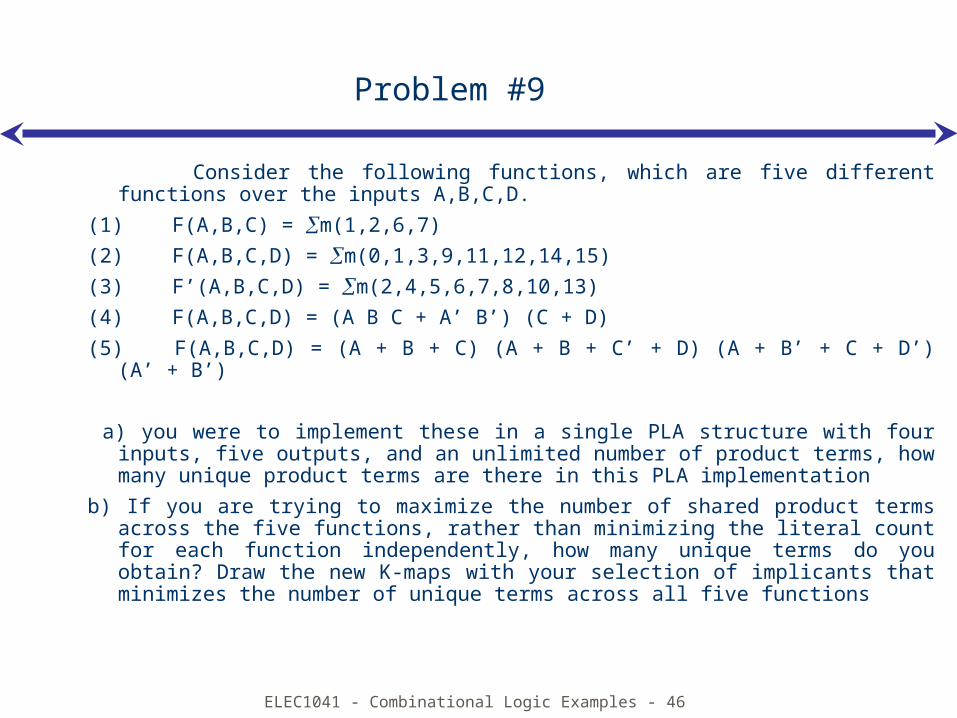
Consider the following functions, which are five different functions over the inputs A,B,C,D.
(1) F(A,B,C) = m(1,2,6,7)
(2) F(A,B,C,D) = m(0,1,3,9,11,12,14,15)
(3) F’(A,B,C,D) = m(2,4,5,6,7,8,10,13)
(4) F(A,B,C,D) = (A B C + A’ B’) (C + D)
(5) F(A,B,C,D) = (A + B + C) (A + B + C’ + D) (A + B’ + C + D’) (A’ + B’)
a) you were to implement these in a single PLA structure with four inputs, five outputs, and an unlimited number of product terms, how many unique product terms are there in this PLA implementation
b) If you are trying to maximize the number of shared product terms across the five functions, rather than minimizing the literal count for each function independently, how many unique terms do you obtain? Draw the new K-maps with your selection of implicants that minimizes the number of unique terms across all five functions
ELEC1041 - Combinational Logic Examples - 47
Problem #9 Solution (1/2)
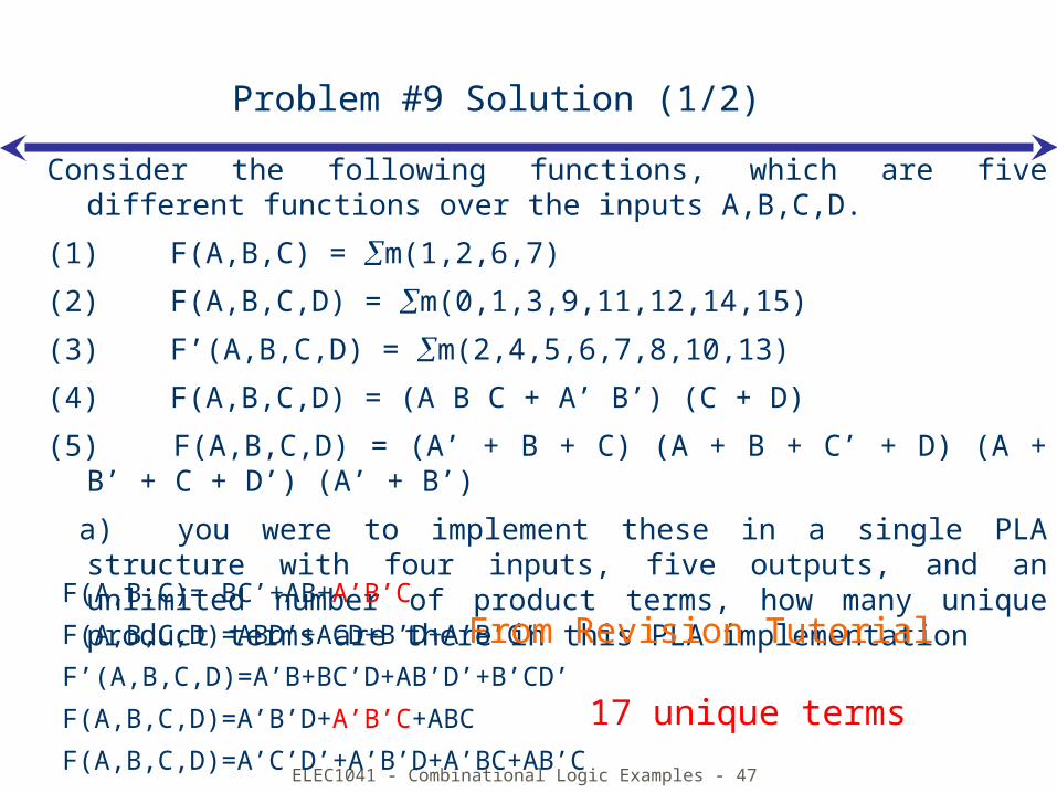
Consider the following functions, which are five different functions over the inputs A,B,C,D.
(1) F(A,B,C) = m(1,2,6,7)
(2) F(A,B,C,D) = m(0,1,3,9,11,12,14,15)
(3) F’(A,B,C,D) = m(2,4,5,6,7,8,10,13)
(4) F(A,B,C,D) = (A B C + A’ B’) (C + D)
(5) F(A,B,C,D) = (A’ + B + C) (A + B + C’ + D) (A + B’ + C + D’) (A’ + B’)
a) you were to implement these in a single PLA structure with four inputs, five outputs, and an unlimited number of product terms, how many unique product terms are there in this PLA implementation
F(A,B,C)= BC’+AB+A’B’C
F(A,B,C,D)=ABD’+ACD+B’D+A’B’C’
F’(A,B,C,D)=A’B+BC’D+AB’D’+B’CD’
F(A,B,C,D)=A’B’D+A’B’C+ABC
F(A,B,C,D)=A’C’D’+A’B’D+A’BC+AB’C
From Revision Tutorial
17 unique terms
ELEC1041 - Combinational Logic Examples - 48
Problem #9 Solution (2/2)
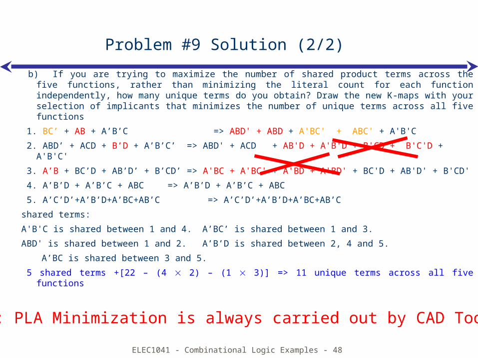
b) If you are trying to maximize the number of shared product terms across the five functions, rather than minimizing the literal count for each function independently, how many unique terms do you obtain? Draw the new K-maps with your selection of implicants that minimizes the number of unique terms across all five functions
1. BC’ + AB + A’B’C => ABD' + ABD + A'BC' + ABC' + A'B'C
2. ABD’ + ACD + B’D + A’B’C’ => ABD' + ACD + AB'D + A'B'D + B'CD + B'C'D + A'B'C'
3. A’B + BC’D + AB’D’ + B’CD’ => A'BC + A'BC' + A'BD + A'BD' + BC'D + AB'D' + B'CD'
4. A’B’D + A’B’C + ABC => A’B’D + A’B’C + ABC
5. A’C’D’+A’B’D+A’BC+AB’C => A’C’D’+A’B’D+A’BC+AB’C
shared terms:
A'B'C is shared between 1 and 4. A’BC’ is shared between 1 and 3.
ABD' is shared between 1 and 2. A’B’D is shared between 2, 4 and 5.
A’BC is shared between 3 and 5.
5 shared terms +[22 – (4 2) – (1 3)] => 11 unique terms across all five functions
NOTE: PLA Minimization is always carried out by CAD Tools
ELEC1041 - Combinational Logic Examples - 49
Problem #10
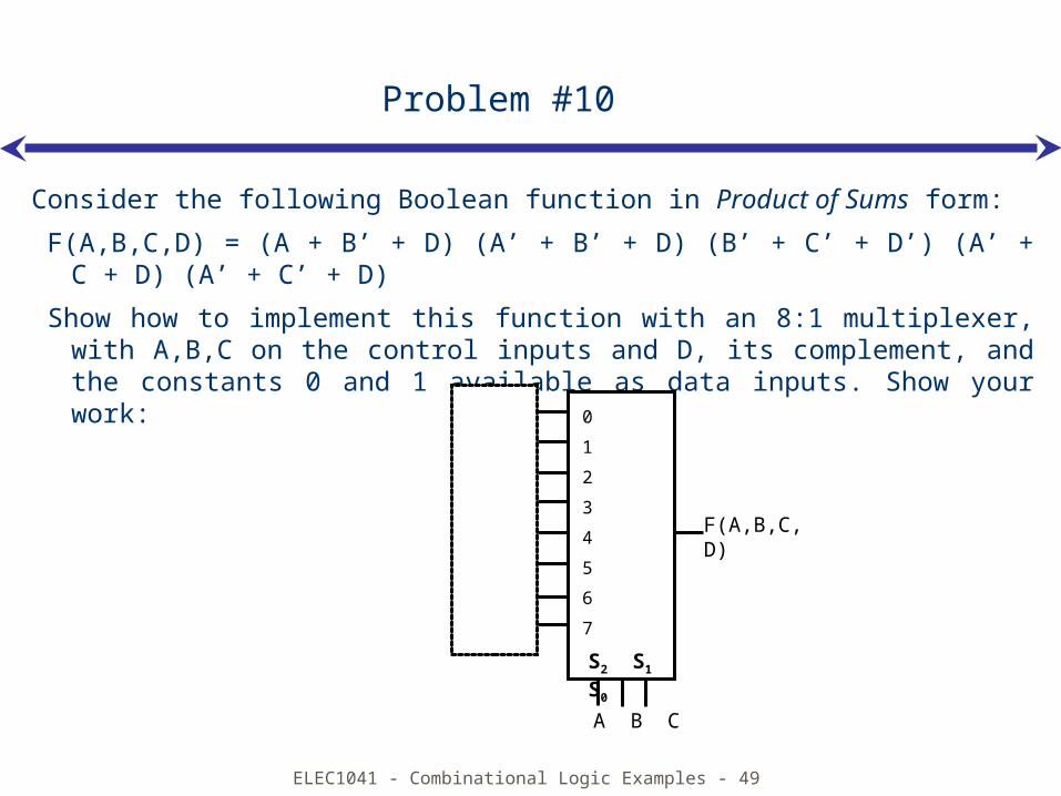
Consider the following Boolean function in Product of Sums form:
F(A,B,C,D) = (A + B’ + D) (A’ + B’ + D) (B’ + C’ + D’) (A’ + C + D) (A’ + C’ + D)
Show how to implement this function with an 8:1 multiplexer, with A,B,C on the control inputs and D, its complement, and the constants 0 and 1 available as data inputs. Show your work:
0
1
2
3
4
5
6
7
F(A,B,C,D)
A B C
S2 S1 S0
ELEC1041 - Combinational Logic Examples - 50
Problem #10 Solution (1/2)
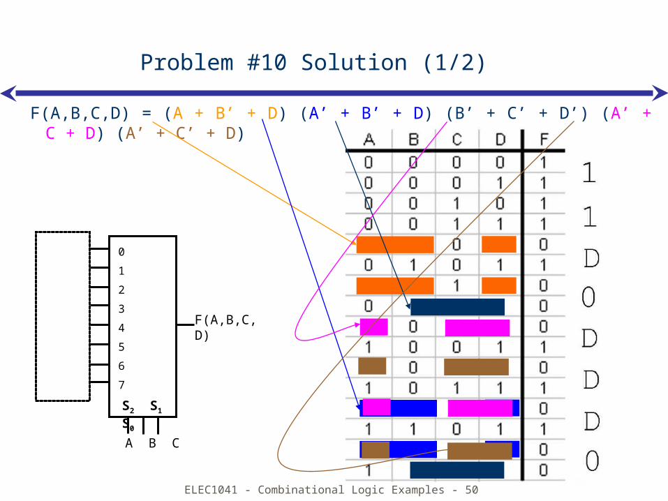
F(A,B,C,D) = (A + B’ + D) (A’ + B’ + D) (B’ + C’ + D’) (A’ + C + D) (A’ + C’ + D)
0
1
2
3
4
5
6
7
F(A,B,C,D)
A B C
S2 S1 S0
ELEC1041 - Combinational Logic Examples - 51
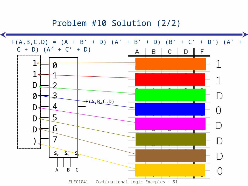
Problem #10 Solution (2/2)
F(A,B,C,D) = (A + B’ + D) (A’ + B’ + D) (B’ + C’ + D’) (A’ + C + D) (A’ + C’ + D)
01234567
F(A,B,C,D)
A B C
S2 S1 S0
11D0DDD)
ELEC1041 - Combinational Logic Examples - 52
Problem #11
Consider a variation on the calendar combinational subsystem that works as follows. Given the inputs MONTH (1-12), DAY (1-31), and LEAP_YEAR flag, the subsystem generates the output DAY_OF_YEAR (1-365 or 366). In this problem, you will design the subsystem to the block diagram level only.
(a) One block maps the month into a day offset into the year. Identify the inputs and outputs and their bit widths. Use any formal specification method you wish (e.g., truth tables, ROM contents, equations, hardware description language, etc.) to describe the function of this block.
(b) You may assume any width binary adder you may require. Indicate how the adder is composed with the block of part (a) and any other blocks or inputs to compute the correct output. Be sure to describe how you deal with the LEAP_YEAR input
ELEC1041 - Combinational Logic Examples - 53
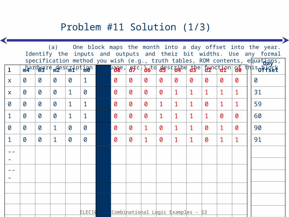
Problem #11 Solution (1/3)
(a) One block maps the month into a day offset into the year. Identify the inputs and outputs and their bit widths. Use any formal specification method you wish (e.g., truth tables, ROM contents, equations, hardware description language, etc.) to describe the function of this blockl m
4m3
m2
m1
m0
d8 d7 d6 d5 d4 d3 d2 d1 d0
x 0 0 0 0 1 0 0 0 0 0 0 0 0 0
x 0 0 0 1 0 0 0 0 0 1 1 1 1 1
0 0 0 0 1 1 0 0 0 1 1 1 0 1 1
1 0 0 0 1 1 0 0 0 1 1 1 1 0 0
0 0 0 1 0 0 0 0 1 0 1 1 0 1 0
1 0 0 1 0 0 0 0 1 0 1 1 0 1 1
---
---
Day Offset
0
31
59
60
90
91
ELEC1041 - Combinational Logic Examples - 54
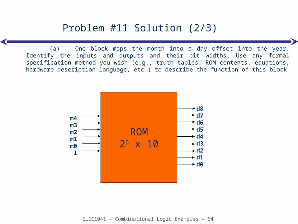
Problem #11 Solution (2/3)
(a) One block maps the month into a day offset into the year. Identify the inputs and outputs and their bit widths. Use any formal specification method you wish (e.g., truth tables, ROM contents, equations, hardware description language, etc.) to describe the function of this block
ROM26 x 10
m4m3m2m1m0
l
d8d7d6d5d4d3d2d1d0
ELEC1041 - Combinational Logic Examples - 55
Problem #11 Solution (3/3)
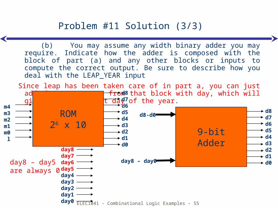
(b) You may assume any width binary adder you may require. Indicate how the adder is composed with the block of part (a) and any other blocks or inputs to compute the correct output. Be sure to describe how you deal with the LEAP_YEAR input
Since leap has been taken care of in part a, you can just add whatever output from that block with day, which will give you the correct day of the year.
d8d7d6d5d4d3d2d1d0
ROM26 x 10
m4m3m2m1m0
l
d8d7d6d5d4d3d2d1d0
9-bitAdder
d8-d0
day8 – day0
day8day7day6day5day4day3day2day1day0
day8 – day5 are always 0
ELEC1041 - Combinational Logic Examples - 56
Problem #12
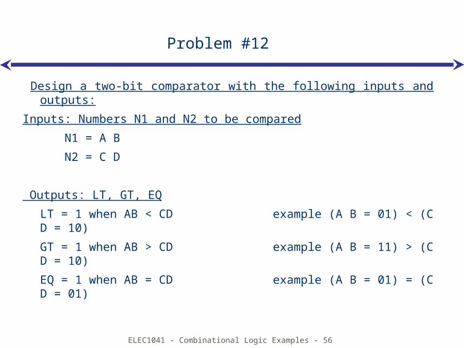
Design a two-bit comparator with the following inputs and outputs:
Inputs: Numbers N1 and N2 to be compared
N1 = A B
N2 = C D
Outputs: LT, GT, EQ
LT = 1 when AB < CD example (A B = 01) < (C D = 10)
GT = 1 when AB > CD example (A B = 11) > (C D = 10)
EQ = 1 when AB = CD example (A B = 01) = (C D = 01)
ELEC1041 - Combinational Logic Examples - 57
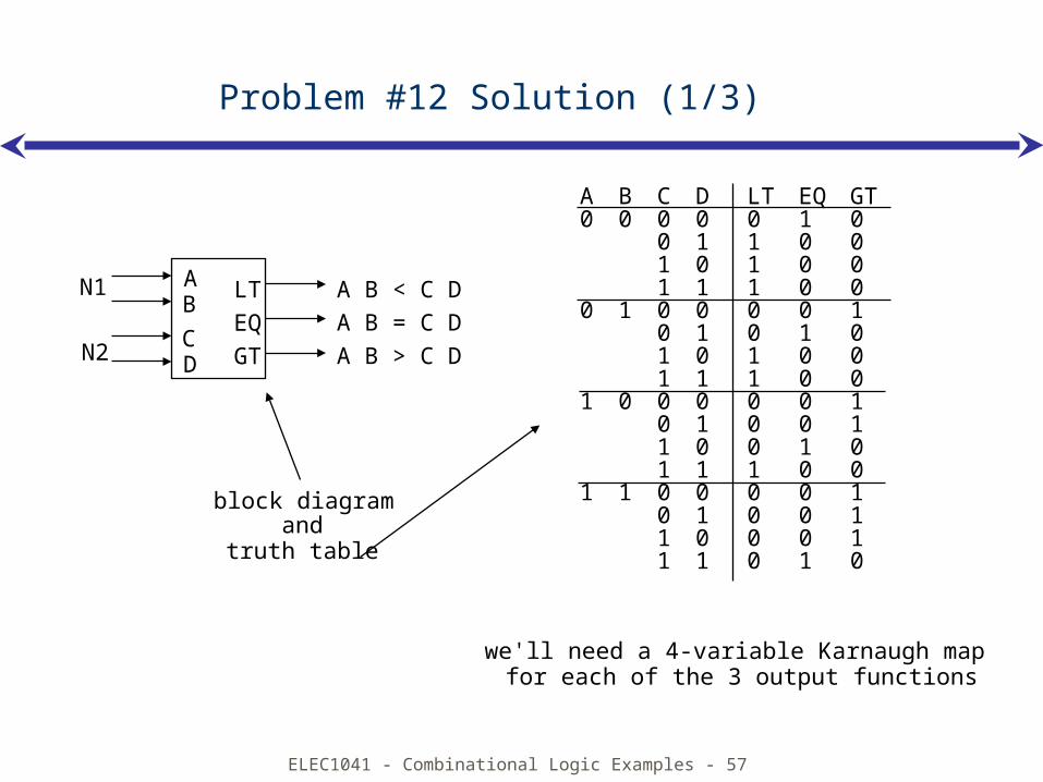
we'll need a 4-variable Karnaugh map for each of the 3 output functions
Problem #12 Solution (1/3)
block diagram
LTEQGT
A B < C DA B = C DA B > C D
AB
CD
N1
N2
A B C D LT EQ GT0 0 0 0 0 1 0
0 1 1 0 01 0 1 0 01 1 1 0 0
0 1 0 0 0 0 10 1 0 1 01 0 1 0 01 1 1 0 0
1 0 0 0 0 0 10 1 0 0 11 0 0 1 01 1 1 0 0
1 1 0 0 0 0 10 1 0 0 11 0 0 0 11 1 0 1 0
andtruth table
ELEC1041 - Combinational Logic Examples - 58
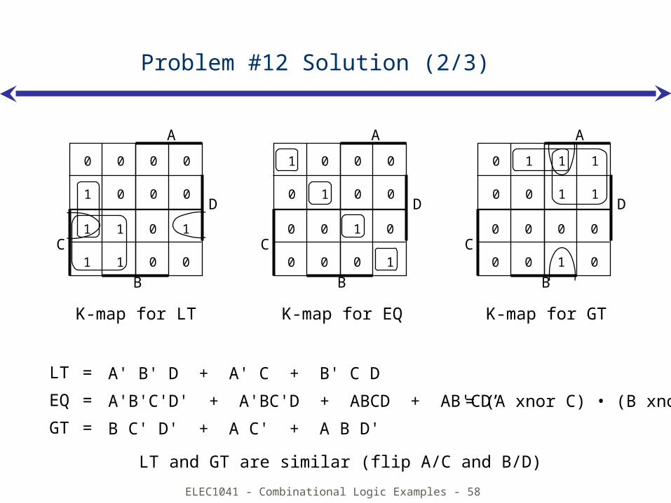
A' B' D + A' C + B' C D
B C' D' + A C' + A B D'
LT =
EQ =
GT =
K-map for EQK-map for LT K-map for GT
Problem #12 Solution (2/3)
0 0
1 0
0 0
0 0D
A
1 1
1 1
0 1
0 0
B
C
1 0
0 1
0 0
0 0D
A
0 0
0 0
1 0
0 1
B
C
0 1
0 0
1 1
1 1D
A
0 0
0 0
0 0
1 0
B
C
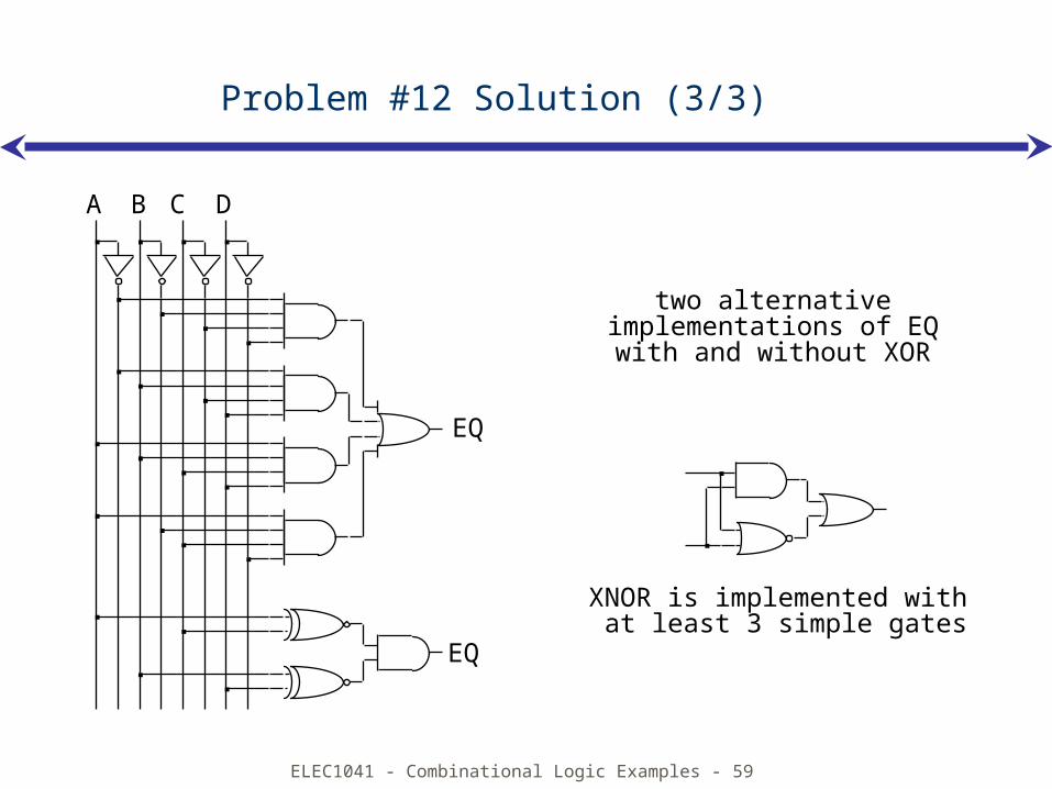
= (A xnor C) • (B xnor D)
LT and GT are similar (flip A/C and B/D)
A'B'C'D' + A'BC'D + ABCD + AB'CD’
ELEC1041 - Combinational Logic Examples - 59
two alternativeimplementations of EQwith and without XOR
XNOR is implemented with at least 3 simple gates
A B C D
EQ
EQ
Problem #12 Solution (3/3)
ELEC1041 - Combinational Logic Examples - 60
Problem #13
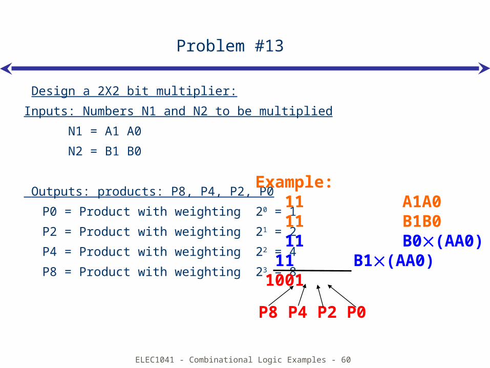
Design a 2X2 bit multiplier:
Inputs: Numbers N1 and N2 to be multiplied
N1 = A1 A0
N2 = B1 B0
Outputs: products: P8, P4, P2, P0
P0 = Product with weighting 20 = 1
P2 = Product with weighting 21 = 2
P4 = Product with weighting 22 = 4
P8 = Product with weighting 23 = 8
Example: 11 A1A0 11 B1B0 11 B0(AA0) 11 B1(AA0) 1001 P8 P4 P2 P0
ELEC1041 - Combinational Logic Examples - 61
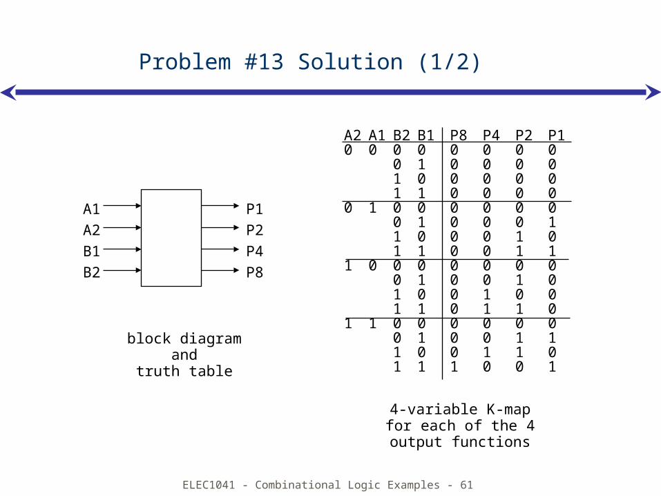
block diagramand
truth table
4-variable K-mapfor each of the 4output functions
A2 A1 B2 B1 P8 P4 P2 P10 0 0 0 0 0 0 0
0 1 0 0 0 01 0 0 0 0 01 1 0 0 0 0
0 1 0 0 0 0 0 00 1 0 0 0 11 0 0 0 1 01 1 0 0 1 1
1 0 0 0 0 0 0 00 1 0 0 1 01 0 0 1 0 01 1 0 1 1 0
1 1 0 0 0 0 0 00 1 0 0 1 11 0 0 1 1 01 1 1 0 0 1
Problem #13 Solution (1/2)
P1P2P4P8
A1A2B1B2
ELEC1041 - Combinational Logic Examples - 62
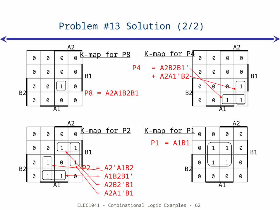
K-map for P8 K-map for P4
K-map for P2 K-map for P1
Problem #13 Solution (2/2)
0 0
0 0
0 0
0 0B1
A2
0 0
0 0
0 1
1 1
A1
B2
0 0
0 1
0 0
1 0B1
A2
0 1
0 0
1 0
0 0
A1
B2
0 0
0 0
0 0
1 1B1
A2
0 1
0 1
0 1
1 0
A1
B2
0 0
0 0
0 0
0 0B1
A2
0 0
0 0
1 0
0 0
A1
B2 P8 = A2A1B2B1
P4= A2B2B1'+ A2A1'B2
P2 = A2'A1B2+ A1B2B1'+ A2B2'B1+ A2A1'B1
P1 = A1B1
ELEC1041 - Combinational Logic Examples - 63
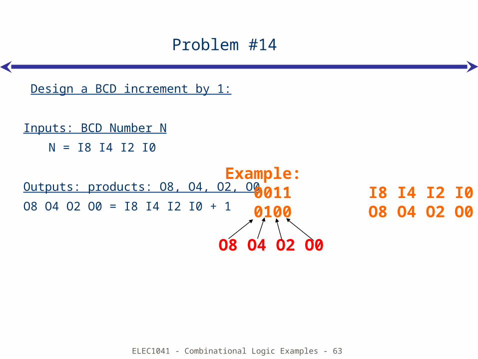
Problem #14
Design a BCD increment by 1:
Inputs: BCD Number N
N = I8 I4 I2 I0
Outputs: products: O8, O4, O2, O0
O8 O4 O2 O0 = I8 I4 I2 I0 + 1
Example: 0011 I8 I4 I2 I0 0100 O8 O4 O2 O0 O8 O4 O2 O0
ELEC1041 - Combinational Logic Examples - 64
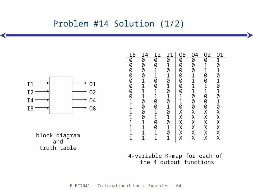
I8 I4 I2 I1 O8 O4 O2 O10 0 0 0 0 0 0 10 0 0 1 0 0 1 00 0 1 0 0 0 1 10 0 1 1 0 1 0 00 1 0 0 0 1 0 10 1 0 1 0 1 1 00 1 1 0 0 1 1 10 1 1 1 1 0 0 01 0 0 0 1 0 0 11 0 0 1 0 0 0 01 0 1 0 X X X X1 0 1 1 X X X X1 1 0 0 X X X X1 1 0 1 X X X X1 1 1 0 X X X X1 1 1 1 X X X Xblock diagram
andtruth table
4-variable K-map for each of the 4 output functions
O1O2O4O8
I1I2I4I8
Problem #14 Solution (1/2)
ELEC1041 - Combinational Logic Examples - 65
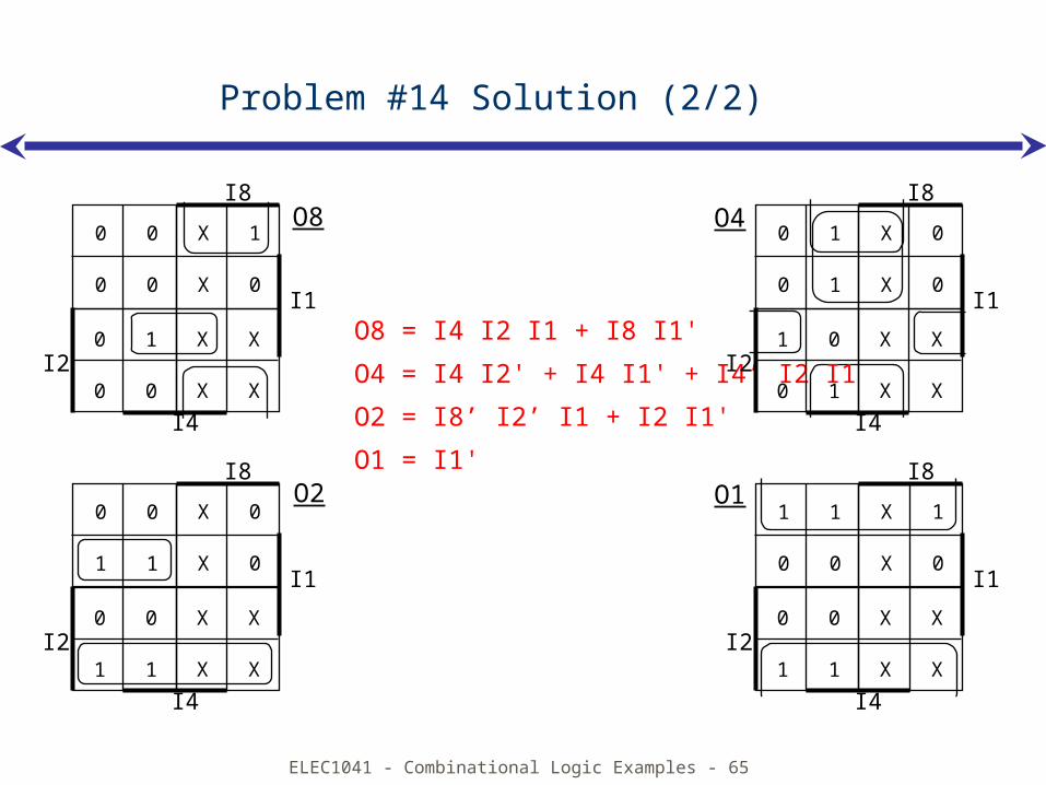
O8 = I4 I2 I1 + I8 I1'
O4 = I4 I2' + I4 I1' + I4’ I2 I1
O2 = I8’ I2’ I1 + I2 I1'
O1 = I1'
O8 O4
O2 O1
Problem #14 Solution (2/2)
0 0
0 0
X 1
X 0I1
I8
0 1
0 0
X X
X X
I4
I2
0 0
1 1
X 0
X 0I1
I8
0 0
1 1
X X
X X
I4
I2
0 1
0 1
X 0
X 0I1
I8
1 0
0 1
X X
X X
I4
I2
1 1
0 0
X 1
X 0I1
I8
0 0
1 1
X X
X X
I4
I2
ELEC1041 - Combinational Logic Examples - 66
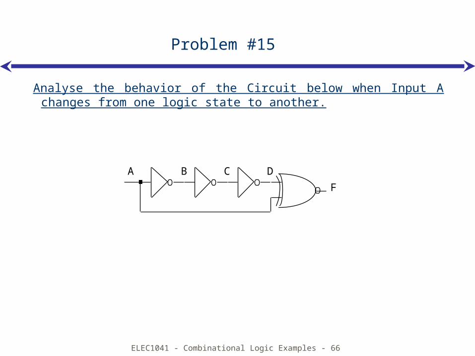
Problem #15
Analyse the behavior of the Circuit below when Input A changes from one logic state to another.
F
A B C D
ELEC1041 - Combinational Logic Examples - 67
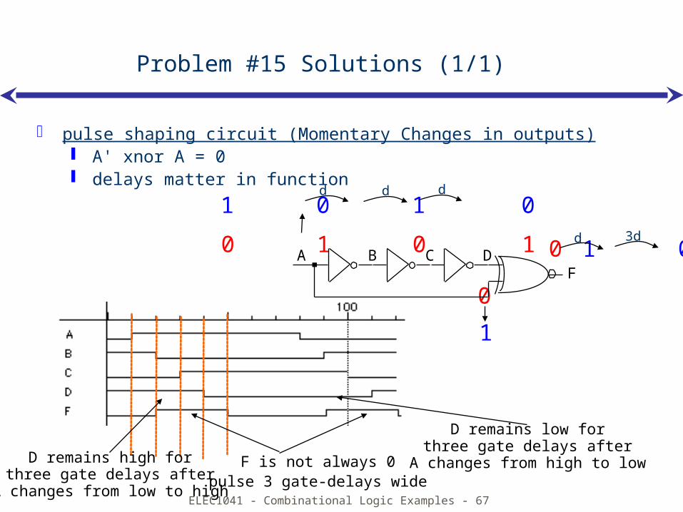
F is not always 0pulse 3 gate-delays wide
Problem #15 Solutions (1/1)
pulse shaping circuit (Momentary Changes in outputs) A' xnor A = 0 delays matter in function
0 1 0 1
0
0
d d d1 0 1 0
1
1 0d 3d
FA B C D
D remains high forthree gate delays after
A changes from low to high
D remains low forthree gate delays after
A changes from high to low
ELEC1041 - Combinational Logic Examples - 68
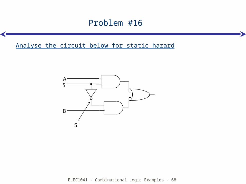
Problem #16
Analyse the circuit below for static hazard
AS
B
S'
ELEC1041 - Combinational Logic Examples - 69
F
A
B
S
S'
F
Static-1 hazard
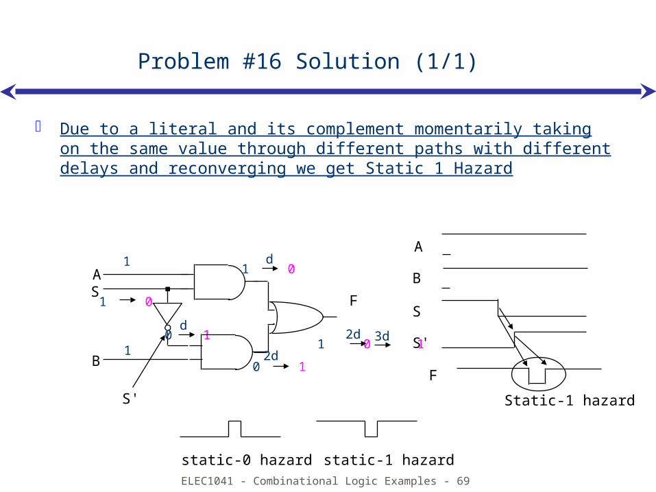
static-0 hazard static-1 hazard
AS
B
S'
Problem #16 Solution (1/1)
Due to a literal and its complement momentarily taking on the same value through different paths with different delays and reconverging we get Static 1 Hazard
1
1
1 0
0 1
1 0
d
d
0 12d
1 0 12d 3d
ELEC1041 - Combinational Logic Examples - 70
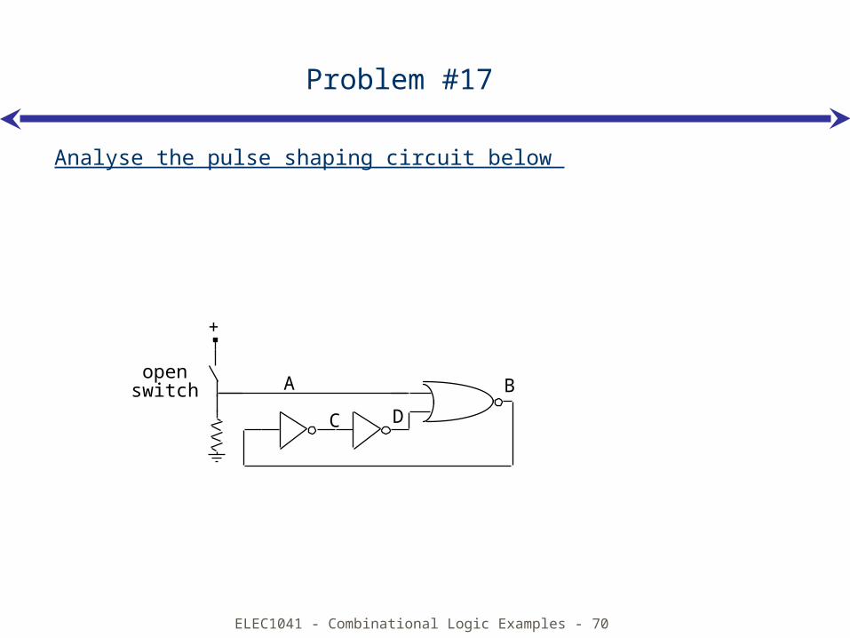
Problem #17
Analyse the pulse shaping circuit below
+
open switch A B
C D
ELEC1041 - Combinational Logic Examples - 71
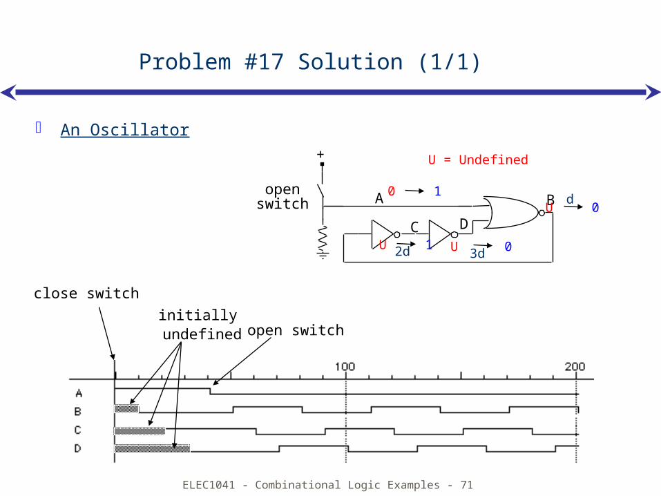
Problem #17 Solution (1/1)
An Oscillator
initially undefined
close switch
open switch
+
open switch A B
C D
0 1U 0
U 1
U = Undefined
d
U 02d 3d
ELEC1041 - Combinational Logic Examples - 72
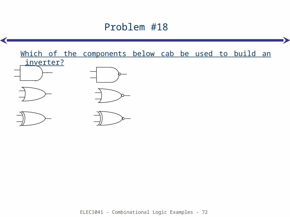
Problem #18
Which of the components below cab be used to build an inverter?
ELEC1041 - Combinational Logic Examples - 73
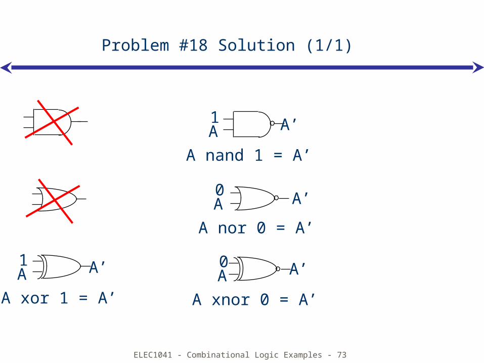
Problem #18 Solution (1/1)
1A A’
A xor 1 = A’
0A A’
A xnor 0 = A’
1A A’
A nand 1 = A’
0A A’
A nor 0 = A’
ELEC1041 - Combinational Logic Examples - 74
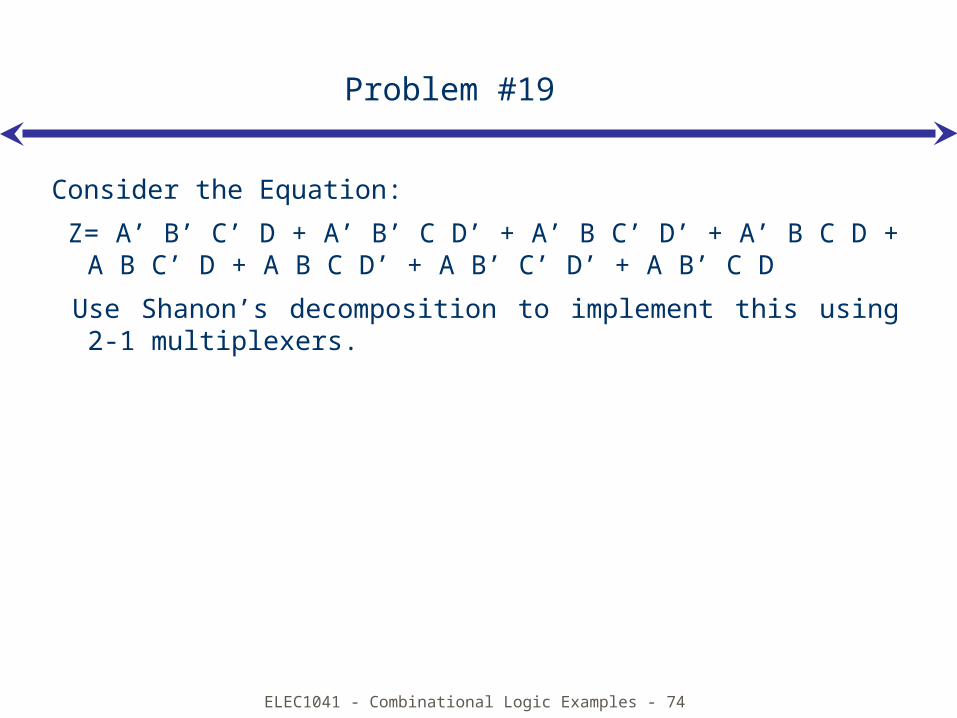
Problem #19
Consider the Equation:
Z= A’ B’ C’ D + A’ B’ C D’ + A’ B C’ D’ + A’ B C D + A B C’ D + A B C D’ + A B’ C’ D’ + A B’ C D
Use Shanon’s decomposition to implement this using 2-1 multiplexers.
ELEC1041 - Combinational Logic Examples - 75
Problem #19 Solution (1/3)
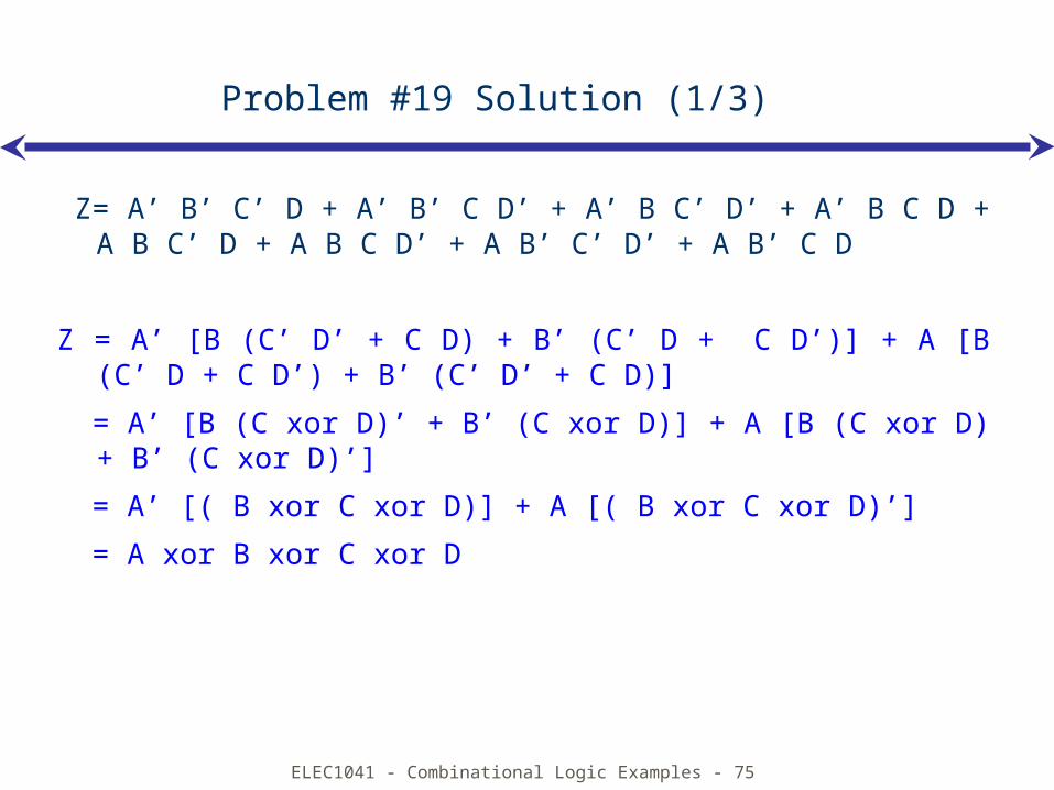
Z= A’ B’ C’ D + A’ B’ C D’ + A’ B C’ D’ + A’ B C D + A B C’ D + A B C D’ + A B’ C’ D’ + A B’ C D
Z = A’ [B (C’ D’ + C D) + B’ (C’ D + C D’)] + A [B (C’ D + C D’) + B’ (C’ D’ + C D)]
= A’ [B (C xor D)’ + B’ (C xor D)] + A [B (C xor D) + B’ (C xor D)’]
= A’ [( B xor C xor D)] + A [( B xor C xor D)’]
= A xor B xor C xor D
ELEC1041 - Combinational Logic Examples - 76
Problem #19 Solution (2/3)
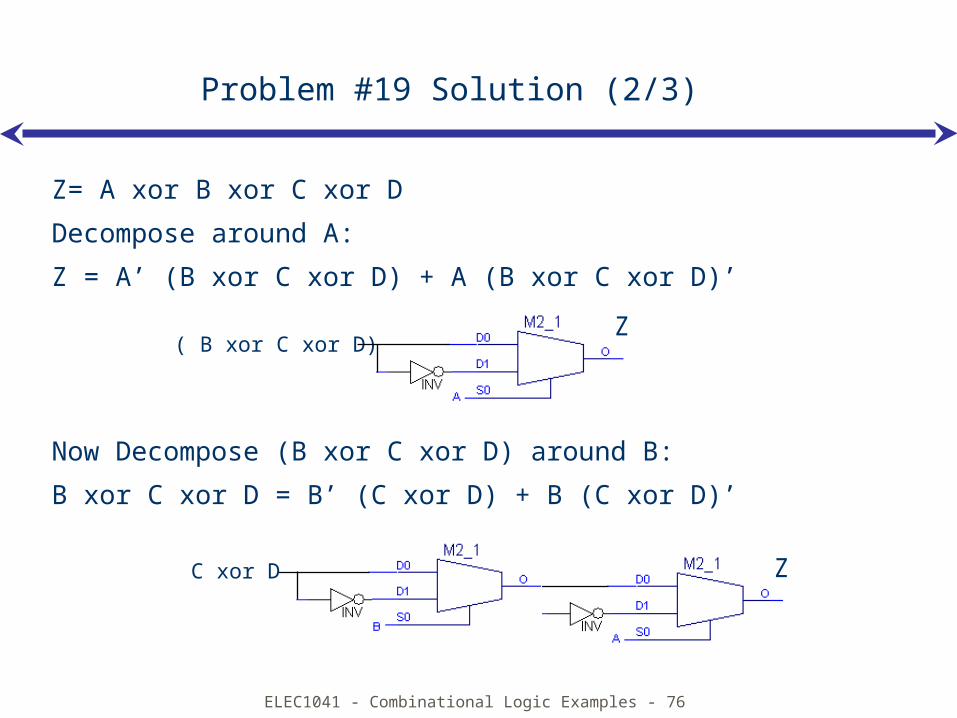
Z= A xor B xor C xor D
Decompose around A:
Z = A’ (B xor C xor D) + A (B xor C xor D)’
Now Decompose (B xor C xor D) around B:
B xor C xor D = B’ (C xor D) + B (C xor D)’
Z( B xor C xor D)
ZC xor D
ELEC1041 - Combinational Logic Examples - 77
Problem #19 Solution (3/3)
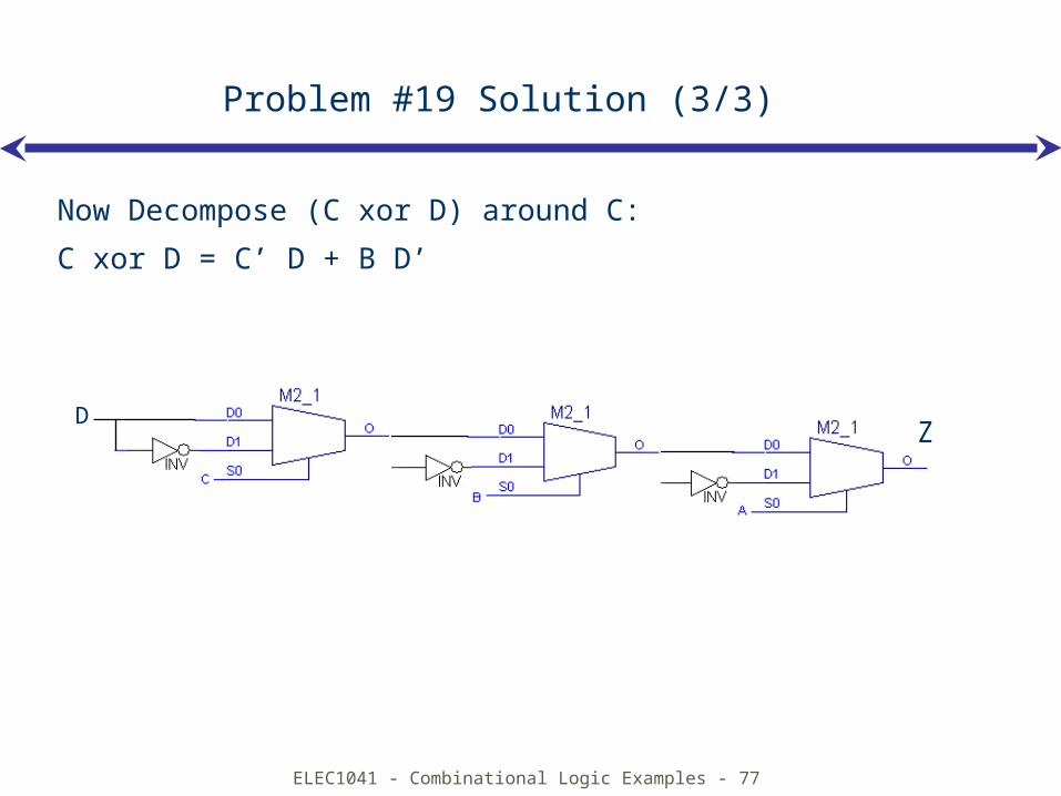
Now Decompose (C xor D) around C:
C xor D = C’ D + B D’
ZD
Related Documents