Egocentric Indoor Localization from Room Layouts and Image Outer Corners Xiaowei Chen and Guoliang Fan School of Electrical and Computer Engineering Oklahoma State University, Stillwater, OK, 74078 USA {xiaowei.chen,guoliang.fan}@okstate.edu Abstract Egocentric indoor localization is an important issue for many in-home smart technologies. Room layouts have been used to characterize indoor scene images by a few typical space configurations defined by boundary lines and junc- tions, which are mostly detectable or inferable by deep learning methods. In this paper, we study camera pose esti- mation for egocentric indoor localization from room layouts that is cast as a PnL (Perspective-n-Line) problem. Specifi- cally, image outer corners (IOCs), which are the intersect- ing points between image borders and room layout bound- aries, are introduced to improve PnL optimization by in- volving additional auxiliary lines in an image. This leads to a new PnL-IOC algorithm where 3D correspondence es- timation of IOCs are jointly solved with camera pose opti- mization in the iterative Gauss-Newton algorithm. Exper- iment results on both simulated and real images show the advantages of PnL-IOC on the accuracy and robustness of camera pose estimation over the existing PnL methods. 1. Introduction With the recent advancement of wearable technologies, egocentric or first-person vision has become an active topic that has led to many useful tools [10, 28]. Room-level in- door localization is often a fundamental step for an ego- centric vision-based in-home assistive tool that can de- liver location-aware assistance or support indoor navigation [3, 32, 29, 23]. Most previous works use deep learning methods for indoor localization that involve a large num- ber of labeled or annotated room images. On the other hand, because most indoor structures usually conform to the Manhattan world assumption [8], indoor scene images can be characterized by different room layouts defined by a few boundary lines and junctions (also called inner cor- ners [26]). During the past decade, indoor layout esti- mation has emerged as an interesting and fast evolving topic with many deep learning-based methods proposed that show great promise and potential [21, 39, 33]. Figure 1. The six room layouts under study where the inner corners and IOCs are colored in yellow and purple, respectively. In this work, we are interested in indoor localization from room layouts via camera pose estimation that involves n correspondences between 3D reference features and their 2D projections. When features are points, this is called the perspective-n-points (PnP) problem [22, 19, 24, 15]. When features are lines, it becomes the PnL (Perspective-n-Line) problem [38]. Given a room layout shown in Figure 1, there are a few boundary lines which intersect at inner corners, which are well defined in a layout map and whose 3D corre- spondences in the world frame may be available with some a priori condition (e.g., the room dimension). Therefore, indoor localization and camera pose estimation from room layouts can be converted to a PnL problem [38]. Of the 11 types of room layouts [21, 25], we focus on 6 of them (Figure 1) with at least three lines (the minimum case of PnL). We propose a new PnL method by introducing image outer corners (IOCs), the intersecting points between image borders and layout boundaries, which are used to cre- ate a preferable condition for the PnL solution by adding more line correspondences. Moreover, 3D correspondence estimation of IOCs is built in the PnL solution, leading to the proposed PnL-IOC method that has two advantages over existing ones: (1) It improves accuracy of camera pose es- timation through IOCs whose 3D correspondences are ini- tialized by solving a linear system and further optimized along with camera pose via the iterative Gaussian-Newton algorithm. (2) It achieves stable and robust results under different noise levels at both the inner and outer corners. 3456

Welcome message from author
This document is posted to help you gain knowledge. Please leave a comment to let me know what you think about it! Share it to your friends and learn new things together.
Transcript

Egocentric Indoor Localization from Room Layouts and Image Outer Corners
Xiaowei Chen and Guoliang FanSchool of Electrical and Computer Engineering
Oklahoma State University, Stillwater, OK, 74078 USA{xiaowei.chen,guoliang.fan}@okstate.edu
Abstract
Egocentric indoor localization is an important issue formany in-home smart technologies. Room layouts have beenused to characterize indoor scene images by a few typicalspace configurations defined by boundary lines and junc-tions, which are mostly detectable or inferable by deeplearning methods. In this paper, we study camera pose esti-mation for egocentric indoor localization from room layoutsthat is cast as a PnL (Perspective-n-Line) problem. Specifi-cally, image outer corners (IOCs), which are the intersect-ing points between image borders and room layout bound-aries, are introduced to improve PnL optimization by in-volving additional auxiliary lines in an image. This leadsto a new PnL-IOC algorithm where 3D correspondence es-timation of IOCs are jointly solved with camera pose opti-mization in the iterative Gauss-Newton algorithm. Exper-iment results on both simulated and real images show theadvantages of PnL-IOC on the accuracy and robustness ofcamera pose estimation over the existing PnL methods.
1. IntroductionWith the recent advancement of wearable technologies,
egocentric or first-person vision has become an active topicthat has led to many useful tools [10, 28]. Room-level in-door localization is often a fundamental step for an ego-centric vision-based in-home assistive tool that can de-liver location-aware assistance or support indoor navigation[3, 32, 29, 23]. Most previous works use deep learningmethods for indoor localization that involve a large num-ber of labeled or annotated room images. On the otherhand, because most indoor structures usually conform tothe Manhattan world assumption [8], indoor scene imagescan be characterized by different room layouts defined bya few boundary lines and junctions (also called inner cor-ners [26]). During the past decade, indoor layout esti-mation has emerged as an interesting and fast evolvingtopic with many deep learning-based methods proposed thatshow great promise and potential [21, 39, 33].
Figure 1. The six room layouts under study where the inner cornersand IOCs are colored in yellow and purple, respectively.
In this work, we are interested in indoor localizationfrom room layouts via camera pose estimation that involvesn correspondences between 3D reference features and their2D projections. When features are points, this is called theperspective-n-points (PnP) problem [22, 19, 24, 15]. Whenfeatures are lines, it becomes the PnL (Perspective-n-Line)problem [38]. Given a room layout shown in Figure 1, thereare a few boundary lines which intersect at inner corners,which are well defined in a layout map and whose 3D corre-spondences in the world frame may be available with somea priori condition (e.g., the room dimension). Therefore,indoor localization and camera pose estimation from roomlayouts can be converted to a PnL problem [38].
Of the 11 types of room layouts [21, 25], we focus on6 of them (Figure 1) with at least three lines (the minimumcase of PnL). We propose a new PnL method by introducingimage outer corners (IOCs), the intersecting points betweenimage borders and layout boundaries, which are used to cre-ate a preferable condition for the PnL solution by addingmore line correspondences. Moreover, 3D correspondenceestimation of IOCs is built in the PnL solution, leading tothe proposed PnL-IOC method that has two advantages overexisting ones: (1) It improves accuracy of camera pose es-timation through IOCs whose 3D correspondences are ini-tialized by solving a linear system and further optimizedalong with camera pose via the iterative Gaussian-Newtonalgorithm. (2) It achieves stable and robust results underdifferent noise levels at both the inner and outer corners.
3456

2. Related workWe briefly review related work in three areas: room lay-
out estimation, PnL/P3L, and recent PnL development.Since the introduction of spatial layout estimation by
[18], room layout estimation has remained an active re-search topic. The early works [18, 34, 11, 36, 12] solvedthe room layout estimation problem using geometry-basedmethods, which took advantage of vanishing points estima-tion. With the development of deep learning, deep learning-based methods, which are robust and accurate when han-dling a wide range of highly challenging scenes, have beenproposed [39, 21, 25]. Furthermore, some high qualitydatasets [6, 9, 41] published recently make deep learningmethods more feasible and accurate. A detailed review forlayout estimation can be found in [39].
In the PnL problem, at least three 2D/3D line corre-spondences are needed because there are 6 DoFs for a 3Dcamera pose and each line correspondence offers two con-straints [17]. When n = 3, it is the P3L (Perspective-three-Line) problem that plays a fundamental role in dealing withthe general PnL problem [38], because the latter is essen-tially constructed by the former. In [13], one early analyticalmethod was proposed to solve the P3L problem that leadsto a closed-form solution by solving an eighth-order poly-nomial. In [5], an algebraic P3L method was proposed thatmay not be stable in the presences of noise. In [4], a spe-cial case of P3L was addressed where three co-planar linesintersect at a point. In [31], a unique P3L problem wasstudied where three lines form a Z-shape in space. In [40],a geometric method was proposed by introducing two inter-mediate frames to simplify the P3L problem formulation.However, a well-known fact about the P3L problem is thatthe solution is not uniquely determined [5].
Most existing PnL studies focus on the cases where n >3 where there are two kinds, iterative and non-iterative. Theearly iterative ones [14, 7, 20] are usually computationallycostly and sensitive to initialization, and easily converge toa local minimum [37]. For recent non-iterative ones, severallinear formulation based methods were proposed [1, 35, 30]that are sensitive to noise and cannot deal with small linesets (n < 6). Some non-iterative PnL methods [2, 27]were developed to deal with small sets that may not be sta-ble due to the underlying linearization scheme. In [40], anon-iterative O(n) solution, named Robust PnL (RPnL),was proposed for the cases of n ≥ 4. Based on RPnL,the Accurate Subset-based PnL (ASPnL) method was pro-posed in [37] that is more accurate on small line sets. How-ever, ASPnL cannot properly deal with the case when thereare only three orthogonal lines intersecting at one junctionpoint, and it was modified in [38] resulting in the SRPnLmethod, which can deal with the aforementioned case anddeliver high accuracy on small line sets. However, SRPnLmay struggle under more lines (n ≥ 8) and strong noise.
3. Proposed Method3.1. Problem statement
The PnL problem is illustrated in Figure 2 where thegoal is to recover rotation Rc
w and translation t of a cam-era from n known 3D reference lines Li = (vw
i , Pwi ) (i =
1, 2, ..., n) along with their corresponding 2D projections onthe image plane denoted as li, where vw
i ∈ R3 is the nor-malized vector giving the direction of the line and Pw
i ∈ R3
is any point on the line in the world coordinate frame.Two intermediate frames are introduced into the reprojec-tion model, the model frame and the new camera frame. Therotation of the model frame with respect to the world frameis Rm
w , and the rotation of the new camera frame with re-spect to the model frame is Rn
m. The rotation of the cameraframe with respect to the new camera frame is Rc
n, wherethe new camera frame can be obtained by rotating the origi-nal camera frame with Rm
w , as Rcn = (Rm
w )T , and similarlyRc
w denotes the rotation of the camera frame with respect tothe world frame. The relationship among those four 3 × 3rotation matrices can be defined as follows:
Rcw = Rc
nRnmRm
w = (Rmw )TRn
mRmw . (1)
Figure 2. Illustration of the PnL-IOC problem.
Given a 2D line li = (si, ei), where si and ei are theendpoints of li, its corresponding 3D line Li and the projec-tion center O can form a projection plane Πi. The normal ofΠi can be easily achieved using the cross product of si andei, which can be defined as nc
i . Suppose Pwi is any point on
Li, and by using the geometrical constraints [17] that P ci ,
the coordinate of Pwi in the camera coordinate frame and
P ci = Rc
wPwi +t, should be perpendicular to the normal nc
i
of the plane Πi, there is a constraint
(nci )
T (RcwP
wi + t) = 0 i = 1, 2, ..., n, (2)
which leads to an analytic solution of t [38].
3457

3.2. Determining initial rotation matrix
From all reference lines Li, line L0 = (vw0 , P
w0 )with the
longest projection length can be selected, then it is used tocalculate the corresponding normal nc
0. A new intermedi-ate model frame [Om −Xm, Ym, Zm] can be formed fromL0 and nc
0 [37]. The origin of the model frame is matchedwith the world frame, and the Y -axis of the model frameis aligned with nc
0 to form the intermediate rotation matrixRm
w = [Xm, Ym, Zm]. After Rmw is determined, the key to
calculate Rcw is to determine Rn
m according to Eq. (1), andRn
m can be expressed by an Euler Angle as
Rnm = Rot(Y, β)Rot(Z, γ)Rot(X,α), (3)
in which Rot(X,α), Rot(Y, β) and Rot(Z, γ) denote ro-tation around the X-axis, Y -axis, and Z-axis in the modelframe, respectively. From the Euler Angle definition, α isthe angle between Z-axis and v
m
0 = Rmwvw
0 [37]. There-fore, if the two unknown variables β and γ are determined,the rotation matrix Rn
m can be obtained, then Rcw can be
calculated from Rnm based on Eq. (1).
For determining Rot(Z, γ), another line L1 = (vw1 , P1)
is selected, whose projection line length in 2D image planeis the second longest, then every remaining line Lk togetherwith line L0 and L1 forms a 3-line subset {L0L1Lk |k = 2, 3, ..., n-1 }, and all given lines can be divided inton − 2 subsets. By using the P3L constraints [40], eachsubset can build an eighth-order polynomial called the P3Lpolynomial [38]. With the P3L polynomial, γ can be deter-mined [37, 38], but there are at most 8 minima for the poly-nomial, which are chosen as the candidate solutions. Af-ter Rot(Z, γ) is determined, from Eq. (3), only Rot(Y, β)needs to be calculated. There are two methods to identifyRot(Y, β). One method is solving Rot(Y, β) alone, whichis for room layouts type 1, type 2, type 3 and type 4, becausethe given 2D/3D line correspondences information in thoselayouts is limited, only 5 or 3 line correspondences. There-fore, the accurate Rot(Y, β) and translation vector cannotbe determined both at the same time. The second methodis determining Rot(Y, β) together with the translation vec-tor for type 0 and type 5 room layouts. For type 0, thereare 8 line correspondences so that rotation and translationrestrict each other to yield a simultaneous result. For type5, there are 5 line correspondences, but the experimental re-sult shows that the second method is more suitable for type5 and can achieve more accurate results.
3.2.1 Retrieving Rot(Y, β) via optimization
From Eq. (3) , Rnm can be expressed as:
Rnm = Rot(Y, β)R′ =
u 0 v0 1 0−v 0 u
r1 r2 r3r4 r5 r6r7 r8 r9
, (4)
in which R′ = Rot(Z, γ)Rot(X,α), u = cosβ andv = sinβ. As Li lies on the plane Πi, vm
i = Rmwvw
i isperpendicular to the plane normal nm
i = Rmwnc
i . There-fore, Rn
m needs to satisfy the constraint that
(nmi )TRn
mvmi = 0 i = 1, 2, ..., n. (5)
In addition, there is a constraint that u2 + v2 = 1. Byusing these two constraints and denoting a new unknowne = [u, v, 1]T , a cost function can be represented as
Eer = eTGe + λ(1− u2 − v2), (6)
in which G obtained from Eq. (5) is a known 3×3 symmet-ric matrix, and λ is a Lagrange multiplier. The minima ofEq. (6) can be obtained by solving the polynomial systemof its first-order optimality condition [37], then u and v canbe determined. Once u and v are determined,Rot(Y, β) canalso be identified. There will be at most 2 minima for calcu-lating Rot(Y, β), and then up to 16 minima for determiningRot(Z, γ) and Rot(Y, β). For each minima, a candidateRn
m can be determined via Eq. (4) and a candidate Rcw can
be obtained by using Eq. (1) .
3.2.2 Solving the rotation and the translation together
As Pmi = Rm
wPwi is also on the plane Πi, we have a con-
straint as
(nmi )T (Rn
mPmi + tm) = 0 i = 1, 2, ..., n, (7)
where
tm = Rmw t = [tmx tmy tmz ]T .
By substituting Eqs. (4) into (5) and (7) and stacking allthese constraints, 2n homogeneous linear equations withparameter vector [u, v, tmx , t
my , t
mz , 1] can be obtained, and
the rotation angle β and the translation vector tm can be es-timated [37]. Then, Rn
m and Rcw can be determined by Eqs.
(4) and (1), respectively. A few candidate solutions can beobtained, and the room layout constraints are used to findthe suitable one.
3.3. Optimizing initial rotation matrix
A more accurate rotation matrix Rcw can be obtained
through optimizing the initial rotational matrix. Firstly lets = [s1 s2 s3]T be the Cayley-Gibbs-Rodriguez (CGR) pa-rameter vector and Rc
w can be expressed using CGR param-eterization [37] as
Rcw =
1
H
[1 + s21 − s22 − s23 2s1s2 − 2s3 2s1s3 + 2s2
2s1s2 + 2s3 1− s21 + s22 − s23 2s2s3 − 2s12s1s3 − 2s2 2s2s3 + 2s1 1− s21 − s22 + s23
],
(8)
3458
whereH = 1+s21+s22+s23. Based on this definition, a least-squares problem with three variables can be reconstructed,and then solved by a single Gauss-Newton step. Accordingto Eq. (2), the rotation and translation can be parameterized,and form the linear system as[
A B][ r
t
]= 0, (9)
where r = [1, s1, s2, s3, s21, s1s2, s1s3, s
23, s2s3, s
23]T .
From Eq. (9), t = −(BTB)−1BTAr and substituting tinto Eq. (9), we have
Er = 0, (10)
where E = A − (BTB)−1BTA. Finally, we obtain theleast-squares problem as follows
ε =
n∑i=1
||Eir||2, (11)
where Ei is a 3 × 10 matrix that can be determined ahead,and the Gauss-Newton method can be used to solve theleast-squares problem. Once the refined r is obtained, theoptimized initial Rc
w and t can be determined. Then thecamera origin in the world frame Ow
c can be evaluated basedon Rc
w and t as
Owc = −(Rc
w)T t, (12)
and because Owc must be inside the room, we can use this
constraint to obtain the final Rcw and t from several can-
didates mentioned above. This optimization step has beenproven to drastically improve numerical precision [37].
3.4. 3D correspondence estimation of IOCs
In a given layout, IOCs are relatively easy to detect.Then we need to evaluate the 3D correspondences of IOCsin the world frame to get more 2D/3D line correspondencesfor camera pose estimation. Specifically, two methods areused for different layouts. For types 0, 1, 2, and 5 (n > 3),there are at least 5 known line correspondences, which issufficient to determine the 3D correspondences of IOCsonly by the following constraint
(nc)TRcwv
w = 0, (13)
in which nc is the norm of the projection plane Πi and sup-posed to be nc
i , and vw is the direction vector of the i-thline in world frame and supposed to be vw
i . Here, we omitthe subscript i, because they are general for every 2D/3Dcorrespondence, and they can be presented as
nc = [nx ny nz]T
Rcw =
r11 r12 r13r21 r22 r23r31 r32 r33
.
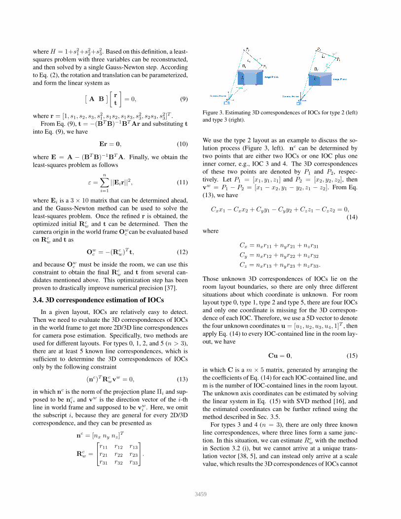
Figure 3. Estimating 3D correspondences of IOCs for type 2 (left)and type 3 (right).
We use the type 2 layout as an example to discuss the so-lution process (Figure 3, left). nc can be determined bytwo points that are either two IOCs or one IOC plus oneinner corner, e.g., IOC 3 and 4. The 3D correspondencesof these two points are denoted by P1 and P2, respec-tively. Let P1 = [x1, y1, z1] and P2 = [x2, y2, z2], thenvw = P1 − P2 = [x1 − x2, y1 − y2, z1 − z2]. From Eq.(13), we have
Cxx1 − Cxx2 + Cyy1 − Cyy2 + Czz1 − Czz2 = 0,(14)
where
Cx = nxr11 + nyr21 + nzr31
Cy = nxr12 + nyr22 + nzr32
Cz = nxr13 + nyr23 + nzr33.
Those unknown 3D correspondences of IOCs lie on theroom layout boundaries, so there are only three differentsituations about which coordinate is unknown. For roomlayout type 0, type 1, type 2 and type 5, there are four IOCsand only one coordinate is missing for the 3D correspon-dence of each IOC. Therefore, we use a 5D vector to denotethe four unknown coordinates u = [u1, u2, u3, u4, 1]T , thenapply Eq. (14) to every IOC-contained line in the room lay-out, we have
Cu = 0, (15)
in which C is a m × 5 matrix, generated by arranging thethe coefficients of Eq. (14) for each IOC-contained line, andm is the number of IOC-contained lines in the room layout.The unknown axis coordinates can be estimated by solvingthe linear system in Eq. (15) with SVD method [16], andthe estimated coordinates can be further refined using themethod described in Sec. 3.5.
For types 3 and 4 (n = 3), there are only three knownline correspondences, where three lines form a same junc-tion. In this situation, we can estimate Rc
w with the methodin Section 3.2 (i), but we cannot arrive at a unique trans-lation vector [38, 5], and can instead only arrive at a scalevalue, which results the 3D correspondences of IOCs cannot
3459

be determined uniquely. To get the unique value, we assumecamera height (cH) is available. The camera height yields aconstraint between Rc
w and translation t with regard to Eq.(12), because the Y coordinate of Oc
w is the camera height,but cH can be X or Z coordinate in the world coordinatesystem. Letting t = [tx ty tz]T and from Eq. (12) we have
r12tx + r22ty + r32tz + cH = 0. (16)
Here, we use the room layout type 3 as the example to de-scribe the solution process (Figure 3, right). Each pointPw(the subscript is omitted) on the line Li, such as P1 orP2, defined as Pw = [Px Py Pz]T , must satisfy the geomet-rical constraints in Eq. (2). Therefore, we have
AxPx +AyPy +AzPz +Atxtx +Aty ty +Atz tz = 0,(17)
where
Ax = nxr11 + nyr21 + nzr31,
Ay = nxr12 + nyr22 + nzr32,
Az = nxr13 + nyr23 + nzr33,
Atx = nx, Aty = ny, Atz = nz.
For type 3 and type 4, there are six unknown parameters in-cluding three unknown coordinates and the translation vec-tor for every layout. Thus, we set all the unknowns asthe parameter vector [u1, u2, u3, tx, ty, tz, 1]T and stack allconstraints in Eq. (16) and Eq. (17) for related points inevery line, to yield
A[u1, u2, u3, tx, ty, tz, 1]T = 0, (18)
in which A can be obtained by Ax, Ay , Az , Atx , Aty , Atz ,known coordinates of 3D correspondences of IOCs and in-ner corners in every line. The initial unknown coordinatesand translation vector can be estimated by solving the linearsystem in Eq. (18) with SVD.
3.5. Camera pose optimization via IOC refinement
To further improve camera pose estimation, we need toimprove 3D correspondence estimation of IOCs. First, wejointly refine the rotation matrix and 3D correspondence ofIOCs together, and use the refined 3D correspondences ofIOCs to re-estimate the camera pose. The pose estimationproblem is converted into a least-squares problem with threevariables related to the rotation matrixRc
w and the unknown3D correspondences of IOCs. From Eq. (2), we have
(nc)TRcwP
w = −(nc)T t, (19)
in which nc(nci ) and Pw(Pw
i ) is general for every 2D/3Dcorrespondence. Rc
w can be represented with the Cayley pa-rameterization as Eq. (8). Now letting Pw = [Px, Py, Pz],Eq. (19) can be transformed into the following matrix form
Mr = Nt, (20)
where
N = −(nc)T ,
M =
nxPx + nyPy + nzPz
2nzPy − 2nyPz
2nxPz − 2nzPx
2nyPx − 2nxPy
nxPx − nyPy − nzPz
2nyPx + 2nxPy
2nzPx + 2nxPz
nyPy − nxPx − nzPz
2nzPy + 2nyPz
nzPz − nxPx − nyPy
,
and r = [1, s1, s2, s3, s21, s1s2, s1s3, s
23, s2s3, s
23]T . Here
we need to add unknown coordinates from 3D correspon-dences of IOCs to the parameter vector. The unknown co-ordinate is on the X-axis, Y -axis, or Z-axis, then the un-known parameter needs to be extracted from matrix M andadded to the parameter vector. According to three differentsituations, the added part is
rx = [s4, s4s2, s4s3, s4s21, s4s1s2, s4s1s3, s4s
22, s4s
23]T ,
ry = [s5, s5s1, s5s3, s5s21, s5s1s2, s5s
22, s5s2s3, s5s
23]T ,
or
rz = [s6, s6s1, s6s2, s6s21, s6s1s3, s6s
22, s6s2s3, s6s
23]T .
We can add the unknowns vectors rx, ry , or rz to the pa-rameter vector according to different situations. The newparameter vector will be r = [rT rTx ]T , r = [rT rTy ]T orr = [rT rTz ]T , and M will become M as
nyPy + nzPz
2nzPy − 2nyPz
2nxPz
−2nxPy
−nyPy − nzPz
2nxPy
2nxPz
nyPy − nzPz
2nzPy + 2nyPz
nzPz − nyPynx
−2nz
2nynx
2ny
2nz
−nx
−nx
,
nxPx + nzPz
−2nyPz
2nxPz − 2nzPx
2nyPx
nxPx − nzPz
2nyPx
2nzPx + 2nxPz
−nxPx − nzPz
2nyPz
nzPz − nxPxny
2nz
−2nx
−ny
2nxny
2nz
−ny
or
nxPx + nyPy
2nzPy
−2nzPx
2nyPx − 2nxPy
nxPx − nyPy
2nyPx + 2nxPy
2nzPx
nyPy − nxPx
2nzPy
−nxPx − nyPynz
−2ny
2nx
−nz
2nx
−nz
2nynz
.
However, for the 3D correspondences of inner corners, Mwill keep same with M, because the coordinates of the 3Dcorrespondences of inner corners are given and the variablesin (19) are just r and t.The equations can be listed accordingto different situations. Then (20) can be written as
Mr = Nt. (21)
3460

Eq. (21) is satisfied for every reference point, henceMT
1
MT2
...MT
n
r =
N1
N2
...Nn
t⇐⇒ Mr = Nt⇐⇒ t = Cs,
(22)
where C = (NTN)−1NTM, r will change according tothe unknown 3D correspondences of IOCs, and we obtainthe least-squares problem as follows
ε =
n∑i=1
||(M− NC)r||2 =
n∑i=1
||Er||2. (23)
However, this cost function is the 3rd order, and we needto do order reduction in order to use Gauss-Newton. Wesolve this problem using a relinearization technique [22].Let s7 = s21, s8 = s1s2, s9 = s1s3, s10 = s22, s11 =s2s3, s12 = s23. Although we introduce five more parame-ters, we have five more equations, which allow us to reducethe order successfully. Then we can use Gauss-Newton sim-ilar to the one discussed in Section 3.3 to refine Rw
c and 3Dcorrespondences of IOCs. Afterwards, there will be more2D/3D line correspondences which can be used to deter-mine the rotation matrix and translation vector using themethods in Section 3.2 and 3.3. The proposed method, re-ferred to as PnL-IOC, is presented in Algorithm 1.
Algorithm 1: The proposed PnL-IOC method.Input : 2D/3D line correspondence of the specific layoutOutput: Rotation matrix R and translation vector t
1 Rot(X,α)← determined by the longest line2 RzList← Rot(Z, γ) determined by P3L polynomial3 for i← 1 to length of RzList do4 if type 1, type 2, type 3, type 4 then5 RyList← Rot(Y, β) determined by 3.2.16 for j ← 1 to length of RyList do7 Rc
w ←the orthogonal error minimal result8 end for9 else
10 RyList← Rot(Y, β) determined by 3.2.211 for j ← 1 to length of RyList do12 Rc
w ←the orthogonal error minimal result13 end for14 end if15 end for16 if type 0, type 1, type 2, type 5 then17 3D correspondences of IOCs determined by Eq. (15)18 else19 3D correspondences of IOCs determined by Eq. (18)20 end if21 Refine 3D correspondences of IOCs and rotation matrix Rc
w22 Reestimate R and t with additional refined 2D/3D line
correspondences by repeating step 1 to step 1223 return R, t
4. Experiment resultsThe PnL-IOC method is evaluated on both synthetic data
and real images, and compared with leading PnL methodslisted below. All methods are implemented in MATLAB ona MacPro with a 2.3 GHz CPU and 8GB of RAM.
∗ RPnL A non-iterative method, which works well forboth non-redundant (n ≤ 6) and redundant line corre-spondences. However, it is not that accurate in somecases, because it is a suboptimal method [40].
∗ LPnL-Bar-ENull A linear method, which parameter-izes reference lines using barycentric coordinates, anduses the null space solver to tackle the PnL problem.This method is suitable for the cases where n > 6 [38].
∗ ASPnL A subset-based PnL method, which is im-proved based on the RPnL method and represents thestate-of-the-art method. However, this method is notsuitable for room layout type 3 and type 4, becausethe rotation and translation cannot be determined at thesame time for those two types [38].
∗ SRPnL An improved subset-based PnL method, whichis improved based on the ASPnL method and hasgood performance. However, when the line correspon-dences number is increasing, the result is worse thanthat by ASPnL and RPnL [37].
4.1. Experiments with synthetic data
4.1.1 Synthetic data
Using a virtual perspective camera with image size of640× 640 pixels and focal length of 180 pixels, the 3D ref-erence lines are generated based on different room layouttypes. For a specific room layout type, we fix the 3D corre-spondences coordinates of inner corners in the world frameand the initial rotation angle and translation vector, then werandomly change the rotation angle in three different anglesin the range of [-5, 5] and translation vector in three dif-ferent directions in the range of [-3, 3], making sure thatthe generated lines can form a specific room layout. Thenwe project these 3D lines onto the 2D image plane usingthe ground-truth rotation Rtrue and translation ttrue. Somerandomly generated room layouts are shown in Figure 4.
The error metric is defined the same as in [37, 38, 15].R and t denote the estimate results for rotation matrixand translation vector, respectitively. Then rotation error(ErrR) and translation error (Errt) will be calculated as
ErrR(deg) = maxk∈1,2,3
∠(Rtrue(:, k),R(:, k))× 180
π,
Errt(%) =||t− ttrue||||ttrue||
× 100, (24)
3461

Figure 4. Some randomly generated room layout images.
where Rtrue(:, k) and R(:, k) are the k-th column of Rtrue
and R, respectively. ∠ represents the angle difference be-tween Rtrue(:, k) and R(:, k). Depending on the experi-ment, a different level of white Gaussian noise was addedto the 2D image plane.
4.1.2 Different layout results with varying noise
The experiment mainly tests the effects of noise on the ac-curacy of all methods for every room layout. We varied thenoise deviation level δ from 1 to 10 pixels. At each noiselevel, we conducted 1000 independent tests once and ranthree times, and calculated the mean and median errors ofrotation and translation. Figure 5 shows that our proposedmethod yields a steady result as the noise is increased forall room layouts, and the mean errors of rotation and trans-lation are increased almost linearly with the noise levels.For type 3, we find that the proposed method result is al-most the same as the SRPnL method, because for type 3the translation vector is a scale value if determined by thegiven information. After introducing the camera height, wecan determine the unique result. However, there always ex-ists a solution whose orthogonal error is the smallest whenthe noise is added. The solution obtained is the best forthe given information. For type 3, the advantage of ourmethod is not obvious, but for type 4 other PnL methods donot achieve the right rotation. Overall, only our PnL-IOCmethod is robust enough for every room layout.
4.1.3 Computational efficiency
Table 1 shows the computational time with fixed δ = 2,where we conducted 1000 tests and show the average run-ning time in seconds (s). From the results, our proposedmethod is comparable to the others, and even better thanSRPnL for some room types. Considering the high accu-racy and robustness, our method is still competitive.
Methods Time (seconds)type 0 type 1 type 2 type 3 type 4 type 5
ASPnL 0.0066 0.0065 0.0060 0.0072 0.0053 0.0056LPnL-Bar-ENull 0.0038 0.0040 0.0016 N/A N/A 0.0032
RPnL 0.0027 0.0022 0.0023 N/A N/A 0.0020SRPnL 0.0109 0.0091 0.0086 0.0437 0.0393 0.0090
PnL-IOC 0.0073 0.0122 0.0121 0.0277 0.0164 0.0177
Table 1. A comparison of the computational efficiency.
4.2. Experiments with Real Images
We also applied the aforementioned PnL algorithms ona set of room layout images with a known 3D line model.We collected some room layout images in the entry area ofour office. For each image, we detected the inner cornersand IOCs manually, and set 3D correspondences based onthe room dimension information, then established the linecorrespondences between the image lines and the 3D linemodel. We tested the compared algorithms for every roomlayout type. In order to demonstrate the accuracy of theresult, we projected the 3D line model into the image andestimate all the corresponding points reprojection error us-ing the estimated camera pose. Figure 6 shows the type 4and type 5 room layout results, and Table 2 shows the re-projection error for different room types in the real world.From Table 2, the proposed method again outperform othersquantitatively for all six layouts being tested.
Methods Reprojection error (pixels)type 0 type 1 type 2 type 3 type 4 type 5
ASPnL 17.014 4.7613 21.723 1154.51 1154.51 50.052LPnL-Bar-ENull 20.659 5.5603 814.60 N/A N/A 65.780
RPnL 18.308 5.6313 203.27 N/A N/A 187.72SRPnL 600.65 4.7613 21.723 7.91e-12 2.53e+03 287.11
PnL-IOC 16.765 4.3776 6.2870 4.04e-12 8.30e-13 28.551
Table 2. Comparison of the Reprojection error for real images.
5. ConclusionIn this work, we presented a new PnL approach to ego-
centric indoor localization by camera pose estimation fromroom layouts. Specifically, we have introduced IOCs to fa-cilitate the PnL solution by adding more 2D/3D additionalline correspondences. To the best of our knowledge, thisis the first attempt to use IOCs in a room layout to solvethe PnL problem. The key idea of our method is to ini-tialize the 3D correspondences of IOCs by solving a linearsystem and to further optimize these 3D correspondencesalong with camera pose via the iterative Gaussian-Newtonalgorithm. The experimental results demonstrate that ourmethod is more accurate and robust compared with the ex-isting PnL methods at a comparable computational load.
AcknowledgmentThis work is supported in part by the US National Institutes
of Health (NIH) Grant R15AG061833 and the Oklahoma Centerfor the Advancement of Science and Technology (OCAST) GrantHR18-069.
3462

Figure 5. Experimental results on the simulated data under different noise levels (δ = 1, ..., 10). From top to bottom: the mean/medianrotation errors and the mean/median translation errors. From left to right, the results for type 0, type 1, type 2, type 3, type 4, type 5.
Figure 6. Camera pose estimation from real world images using our method and other PnL methods. The first row results are for type 4room layout and the second row for type 5 layout, where RepErr is the reprojection error.
3463

References[1] Y. I. Abdel-Aziz, H. M. Karara, and M. Hauck. Direct
Linear Transformation from Comparator Coordinatesinto Object Space Coordinates in Close-Range Pho-togrammetry*. 81(2):103–107, 2015.
[2] A. Ansar and K. Daniilidis. Linear Pose Estimationfrom Points or Lines. Pattern Analysis and MachineIntelligence, IEEE Transactions on, 25:578– 589, 062003.
[3] V. Bettadapura, I. Essa, and C. Pantofaru. EgocentricField-of-View Localization Using First-Person Point-of-View Devices. In Proc. ICCV, 2015.
[4] V. Caglioti. The planar three-line junction perspectiveproblem with application to the recognition of polygo-nal patterns. Pattern Recognition, 26(11):1603–1618,1993.
[5] H. Chen. Pose determination from line-to-plane corre-spondences: existence condition and closed-form so-lutions. In Proc. ICCV, 1990.
[6] W. Choi, Y.-W. Chao, C. Pantofaru, and S. Savarese.Understanding indoor scenes using 3d geometricphrases. In Proc. CVPR, 2013.
[7] S. Christy and R. Horaud. Iterative Pose Computationfrom Line Correspondences. Computer Vision and Im-age Understanding, 73(1):137–144, 1999.
[8] J. M. Coughlan and A. L. Yuille. Manhattan World:Orientation and Outlier Detection by Bayesian Infer-ence. Neural Computation, 15(5):1063–1088, 2003.
[9] A. Dai, A. Chang, M. Savva, M. Halber, T.Funkhouser, and M. Nießner. Scannet: Richly-annotated 3d reconstructions of indoor scenes. CoRR,abs/1702.04405, 2017.
[10] D. Damen, H. Doughty, G. M. Farinella, S. Fidler, A.Furnari, E. Kazakos, D. Moltisanti, J. Munro, T. Per-rett, W. Price, and M. Wray. Scaling Egocentric Vi-sion: The EPIC-KITCHENS Dataset. In Proc. ECCV,2018.
[11] L. Del Pero, J. Bowdish, D. Fried, B. Kermgard, E.Hartley, and K. Barnard. Bayesian geometric model-ing of indoor scenes. In Proc. CVPR, 2012.
[12] L. Del Pero, J. Bowdish, B. Kermgard, E. Hartley,and K. Barnard. Understanding bayesian rooms usingcomposite 3d object models. In Proc. CVPR, pages153–160, 2013.
[13] M. Dhome, M. Richetin, J.-T. Lapreste, and G. Rives.Determination of the attitude of 3D objects from asingle perspective view. IEEE Transactions on Pat-tern Analysis and Machine Intelligence, 11(12):1265–1278, 1989.
[14] F. Dornaika and C. Garcia. Pose Estimation usingPoint and Line Correspondences. Real-Time Imaging,5(3):215–230, 1999.
[15] L. Ferraz, X. Binefa, and F. Moreno-Noguer. Very FastSolution to the PnP Problem with Algebraic OutlierRejection. In Proc. CVPR, 2014.
[16] W. Gander. Least Squares Fit of Point Clouds, pages339–349. Springer Berlin Heidelberg, Berlin, Heidel-berg, 2004.
[17] R. I. Hartley and A. Zisserman. Multiple View Geom-etry in Computer Vision. Cambridge University Press,ISBN: 0521540518, second edition, 2004.
[18] V. Hedau, D. Hoiem, and D. Forsyth. Recovering thespatial layout of cluttered rooms. In Proc. ICCV, 2009.
[19] J. A. Hesch and S. I. Roumeliotis. A Direct Least-Squares (DLS) method for PnP. In Proc. ICCV, 2011.
[20] R. Kumar and A.R. Hanson. Robust Methods for Es-timating Pose and a Sensitivity Analysis. CVGIP: Im-age Understanding, 60(3):313–342, 1994.
[21] C.-Y. Lee, V. Badrinarayanan, T. Malisiewicz, and A.Rabinovich. RoomNet: End-to-End Room Layout Es-timation. In Proc. ICCV, 2017.
[22] V. Lepetit, F. Moreno-Noguer, and P. Fua. EPnP: Anaccurate O(n) solution to the PnP problem. Interna-tional Journal of Computer Vision, 81, 02 2009.
[23] L. Li, Q. Xu, V. Chandrasekhar, J.-H. Lim, C. Tan, andM. A. Mukawa. A Wearable Virtual Usher for Vision-Based Cognitive Indoor Navigation. IEEE Transac-tions on Cybernetics, 47(4):841–854, 2017.
[24] S. Li, C. Xu, and M. Xie. A Robust O(n) Solution tothe Perspective-n-Point Problem. IEEE transactionson pattern analysis and machine intelligence, 34, 012012.
[25] H. J. Lin, S.-W. Huang, S.-H. Lai, and C.-K. Chiang.Indoor Scene Layout Estimation from a Single Image.In Proc. ICPR, 2018.
[26] H.-J. Lin and S. Lai. Deeproom: 3d room layout andpose estimation from a single image. In ACPR, 2019.
[27] F. M. Mirzaei and S. I. Roumeliotis. Globally optimalpose estimation from line correspondences. In Proc.ICRA, 2011.
[28] T.-H.-C. Nguyen, J.-C. Nebel, and F. Florez-Revuelta.Recognition of Activities of Daily Living with Ego-centric Vision: A Review. Sensors, 16(1), 2016.
[29] S. Orlando, A. Furnari, S. Battiato, and G. Farinella.Image Based Localization with Simulated EgocentricNavigations. In Proc. ICCV, 2019.
[30] B. Pribyl, P. Zemcık, and M. Cadık. Camera PoseEstimation from Lines using Plucker Coordinates. InProc. BMVC, 2015.
3464

[31] L. Qin and F. Zhu. A New Method for Pose Estimationfrom Line Correspondences. Acta Automatica Sinica,34(2):130–134, 2008.
[32] F. Ragusa, A. Furnari, S. Battiato, G. Signorello, andG. M. Farinella. Egocentric Visitors Localization inCultural Sites. J. Comput. Cult. Herit., 12(2), Apr.2019.
[33] Y. Ren, S. Li, C. Chen, and C.-C. J. Kuo. A Coarse-to-Fine Indoor Layout Estimation (CFILE) Method. InProc. ACCV, 2017.
[34] A. G. Schwing, T. Hazan, M. Pollefeys, and R. Urta-sun. Efficient structured prediction for 3d indoor sceneunderstanding. In Proc. CVPR, 2012.
[35] M. Silva, R. Ferreira, and J. Gaspar. Camera Calibra-tion using a Color-Depth Camera: Points and LinesBased DLT including Radial Distortion. In Proc.IROS, 2012.
[36] H. Wang, S. Gould, and D. Koller. Discrimina-tive learning with latent variables for cluttered indoorscene understanding. In Proc. ECCV, 2010.
[37] P. Wang, G. Xu, Y. Cheng, and Q. Yu. Camera pose es-timation from lines: a fast, robust and general method.Machine Vision and Applications, vol. 30, 2019.
[38] C. Xu, L. Zhang, L. Cheng, and R. Koch. Pose Es-timation from Line Correspondences: A CompleteAnalysis and a Series of Solutions. IEEE Transac-tions on Pattern Analysis and Machine Intelligence,39(6):1209–1222, 2017.
[39] C. Yan, B. Shao, H. Zhao, R. Ning, Y. Zhang, andF. Xu. 3D Room Layout Estimation From a Sin-gle RGB Image. IEEE Transactions on Multimedia,22(11):3014–3024, 2020.
[40] L. Zhang, C. Xu, K.-M. Lee, and R. Koch. Robust andEfficient Pose Estimation from Line Correspondences.In Proc. ACCV, 2013.
[41] Y. Zhang, S. Song, E. Yumer, M. Savva, J.-Y. Lee, H.Jin, and T. Funkhouser. Physically-based rendering forindoor scene understanding using convolutional neu-ral networks. CoRR, abs/1612.07429, 2016.
3465
Related Documents


![Egocentric Field-of-View Localization Using First-Person ... · age GSM [24], active badges [31], 802.11b wireless ether-net [16], bluetooth and WAP [2], listeners and beacons [25],](https://static.cupdf.com/doc/110x72/5f526e4368ee1d29c17dad82/egocentric-field-of-view-localization-using-first-person-age-gsm-24-active.jpg)