R. Moreno-Díaz et al. (Eds.): EUROCAST 2007, LNCS 4739, pp. 1119 – 1125, 2007. © Springer-Verlag Berlin Heidelberg 2007 Ego-Motion Computing for Vehicle Velocity Estimation M.A. Sotelo 1 , R. Flores 1 , R. García 1 , M. Ocaña 1 , M.A. García 1 , I. Parra 1 , D. Fernández 1 , M. Gavilán 1 , and J.E. Naranjo 2 1 Department of Electronics, University of Alcalá, Alcalá de Henares, Madrid, Spain {sotelo, rflores, mocana, garrido, parra, llorca}@depeca.uah.es 2 Industrial Automation Institute, CSIC, Arganda del Rey, Madrid, Spain [email protected] Abstract. In this paper, we present a method for computing velocity using a single camera onboard a road vehicle, i.e. an automobile. The use of computer vision provides a reliable method to measure vehicle velocity based on ego- motion computation. By doing so, cumulative errors inherent to odometry- based systems can be reduced to some extent. Road lane markings are the basic features used by the algorithm. They are detected in the image plane and grouped in couples in order to provide geometrically constrained vectors that make viable the computation of vehicle motion in a sequence of images. The applications of this method can be mainly found in the domains of Robotics and Intelligent Vehicles. Keywords: Vision, Ego-motion, Velocity Estimation, Intelligent Vehicles. 1 Introduction Accurate estimation of the vehicle ego-motion with regard to the road is a key element for computer vision-based assisted driving systems. In this method, we propose the use of a single camera onboard a road vehicle in order to provide an estimation of its longitudinal velocity by computational means. The main advantage derived from the use of computer vision for ego-motion computation is the fact that vision is not subject to slippery, contrary to odometry-based systems. We propose to obtain couples of road features, mainly composed of road markings, as the main source of information for computing vehicle ego-motion. Additionally, the use of lane markings allows avoiding the use of complex direct methods [1], [2], [3] for motion estimation. Instead, motion stereo techniques are considered. This technique has previously been deployed in the field of indoor robotics [4]. The method is based on sampling a dynamic scene rapidly (e.g., 25 images per second) and measuring the displacements of features relative to each other in the image sequence. 2 System Description In outdoor scenes where many artificial objects and structures exist, a couple of static points that belong to the same object and are equally distant from the image plane

Welcome message from author
This document is posted to help you gain knowledge. Please leave a comment to let me know what you think about it! Share it to your friends and learn new things together.
Transcript
R. Moreno-Díaz et al. (Eds.): EUROCAST 2007, LNCS 4739, pp. 1119 – 1125, 2007. © Springer-Verlag Berlin Heidelberg 2007
Ego-Motion Computing for Vehicle Velocity Estimation
M.A. Sotelo1, R. Flores1, R. García1, M. Ocaña1, M.A. García1, I. Parra1, D. Fernández1, M. Gavilán1, and J.E. Naranjo2
1 Department of Electronics, University of Alcalá, Alcalá de Henares, Madrid, Spain {sotelo, rflores, mocana, garrido, parra, llorca}@depeca.uah.es
2 Industrial Automation Institute, CSIC, Arganda del Rey, Madrid, Spain [email protected]
Abstract. In this paper, we present a method for computing velocity using a single camera onboard a road vehicle, i.e. an automobile. The use of computer vision provides a reliable method to measure vehicle velocity based on ego-motion computation. By doing so, cumulative errors inherent to odometry-based systems can be reduced to some extent. Road lane markings are the basic features used by the algorithm. They are detected in the image plane and grouped in couples in order to provide geometrically constrained vectors that make viable the computation of vehicle motion in a sequence of images. The applications of this method can be mainly found in the domains of Robotics and Intelligent Vehicles.
Keywords: Vision, Ego-motion, Velocity Estimation, Intelligent Vehicles.
1 Introduction
Accurate estimation of the vehicle ego-motion with regard to the road is a key element for computer vision-based assisted driving systems. In this method, we propose the use of a single camera onboard a road vehicle in order to provide an estimation of its longitudinal velocity by computational means. The main advantage derived from the use of computer vision for ego-motion computation is the fact that vision is not subject to slippery, contrary to odometry-based systems. We propose to obtain couples of road features, mainly composed of road markings, as the main source of information for computing vehicle ego-motion. Additionally, the use of lane markings allows avoiding the use of complex direct methods [1], [2], [3] for motion estimation. Instead, motion stereo techniques are considered. This technique has previously been deployed in the field of indoor robotics [4]. The method is based on sampling a dynamic scene rapidly (e.g., 25 images per second) and measuring the displacements of features relative to each other in the image sequence.
2 System Description
In outdoor scenes where many artificial objects and structures exist, a couple of static points that belong to the same object and are equally distant from the image plane
1120 M.A. Sotelo et al.
may be observed and measured simultaneously. In particular, the left and right edges of lane markings constitute a clear example of coupled points that can be used for computing vehicle ego-motion using perspective projection laws. Let us, then, assume that there are two road points, P1 and P2, with coordinates (X1, Y1, Z1) and (X2, Y2, Z2), where Z stands for the point depth (distance from the image plane). Let us assume that Z1=Z2=Z, which means that both points are equally distant from the image plane. The coordinates of the points in the image plane, p1 and p2, can then be computed as
⎟⎠⎞
⎜⎝⎛ ⋅+⋅+=
⎟⎠⎞
⎜⎝⎛ ⋅+⋅+=
Z
Yfv
Z
Xfup
Z
Yfv
Z
Xfup
vcuc
vcuc
222
111
,
, (1)
where uc and vc represent the coordinates of the principal point in the image plane (optical center), and fu and fv are the camera focal length, given in pixels units, in the u (horizontal) and v (vertical) axes, respectively. Let B=|X1-X2| be the horizontal distance between the road points and b=|x1-x2| the horizontal distance between the corresponding image points. Based on the previous statement, b=fu·B/Z. Finally, let us consider that the camera is translated causing the two road points to move relative to the camera with the velocity (dX/dt, dY/dt, dZ/dt) while fu and B remain constant. In general, the derivative of b with respect to time can be computed as
dt
dZ
Z
b
dt
dZ
Z
Bf
dt
dZ
dZ
db
dt
db u ⋅−=⋅−=⋅=2
(2)
For a couple of road points, the distance from the image plane Z can be computed under the planar road assumption as follows
( )αθ
θ
−⋅=
⎟⎠⎞
⎜⎝⎛= −
tan
tan 1
vfvZ
H (3)
where � stands for the camera pitch angle with respect to the horizontal line parallel to the road, v is the vertical coordinate of the coupled road points in the image plane, and H is the camera height with respect to the road plane. Let us remark that coordinate v can be directly measured from the image, while parameters H and � are supposed to be known.
Based on relations (2) and (3), an equation can be formulated for each couple i of road points equally distant from the image plane. Equation (4) shows a mathematical relation from which vehicle velocity (v=dZ/dt) can be computed.
dt
db
b
Z
dt
dZv i
i
i ⋅−== (4)
Ego-Motion Computing for Vehicle Velocity Estimation 1121
Let Nt represent the number of road point couples found by the algorithm at frame t. The optimal estimation of vehicle velocity v can be done by optimizing the system formed by the Nt equations that can be written at each iteration of the algorithm. Based on the previous statement, the problem can be mathematically formulated as the minimization of the estimation square error SE, represented in equation 5.
( )∑=
−⋅=tN
itii
t
bbN
SE1
2
,
1 (5)
where ib represents the estimation of b for couple i, and bi,t stands for the
measurement of b for couple i at frame t. This criteria leads to the final value provided in equation (6).
∑
∑
= −
−
= −
−
⎟⎟⎠
⎞⎜⎜⎝
⎛
⋅⎟⎟⎠
⎞⎜⎜⎝
⎛
≈t
t
N
i ti
ti
N
i ti
titi
t
Z
b
Z
b
dt
db
v
1
2
1,
1,
1 1,
1,,
(6)
where bi,t-1 represents the measurement of b for couple i at frame t-1, and Zi,t-1 stands for the depth measurement for couple i at frame t-1.
3 Extension of the Method - 3D Visual Odometry
We propose an extension of the method for ego-motion computing based on stereo-vision, achieving what is known as 3D visual odometry. The use of stereo-vision has the advantage of disambiguating the 3D position of detected features in the scene at a given frame. Based on that, feature points are matched between pairs of frames and linked into 3D trajectories. The idea of estimating displacements from two 3-D frames using stereo vision has been previously used in [5] [6] and [7]. The resolution of the equations of the system at each frame is carried out under the non-linear, photogrametric approach using RANSAC. This iterative technique enables the formulation of a robust method that can ignore large numbers of outliers as encountered in real traffic scenes. The resulting method is defined as visual odometry and can be used in conjunction with other sensors, such as GPS, to produce accurate estimates of the vehicle global position. The mathematical details of the method are provided in [8]. The obvious application of the method is to provide on-board driver assistance in navigation tasks, or to provide a means for autonomously navigating a vehicle. The method has been tested in real traffic conditions without using prior knowledge about the scene or the vehicle motion. We provide examples of estimated vehicle trajectories using the proposed method and discuss the key issues for further improvement.
1122 M.A. Sotelo et al.
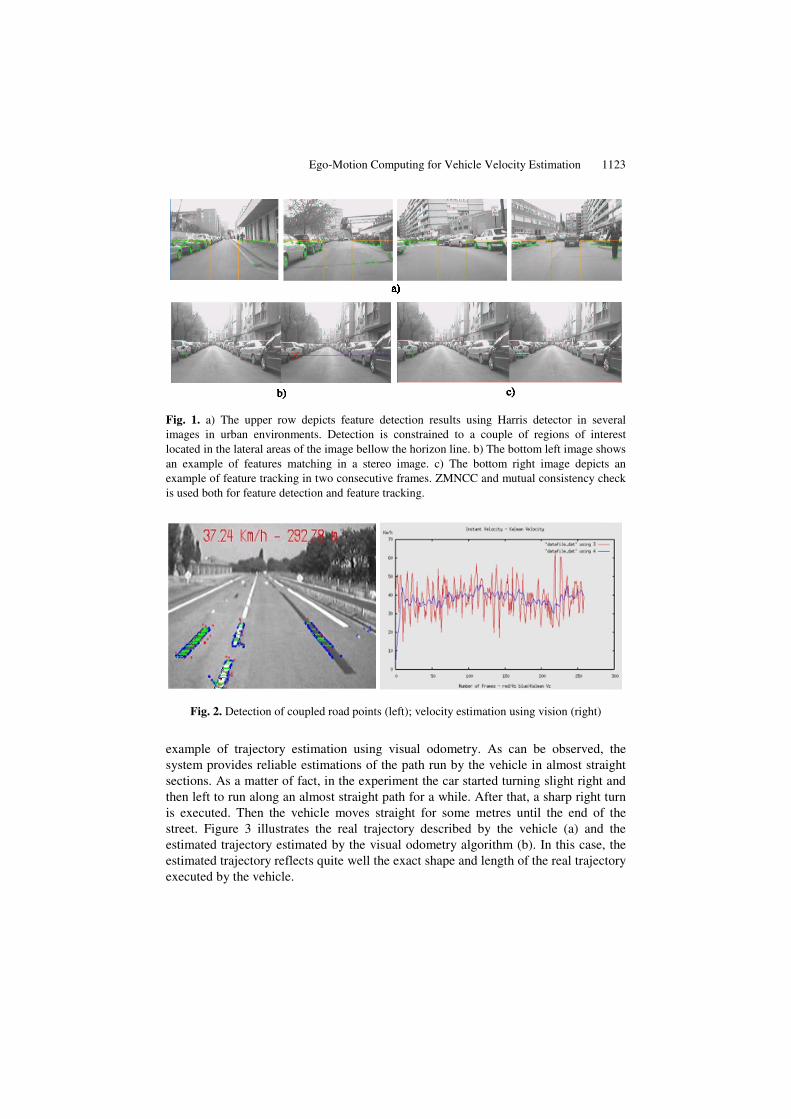
In each frame, Harris corners are detected, since this type of point feature has been found to yield detections that are relatively stable under small to moderate image distortions. As stated in [6], distortions between consecutive frames can be regarded as fairly small when using video input. The feature points are matched at each frame, using the left and rights image of the stereo-vision arrangement, and between pairs of frames. Features are detected in all frames and matches are allowed only between features. A feature in one image is matched to every feature within a fixed distance from it in the next frame, called disparity limit. For the sake of real-time performance, matching is computed over a 7x7 window. Among the wide spectrum of matching techniques that can be used to solve the correspondence problem we implemented the Zero Mean Normalized Cross Correlation (ZMNCC) because of its robustness.
As the window size decreases, the discriminatory power of the area-based criterion gets decreased and some local maxima appear in the searching regions. On the contrary, an increase in the window size causes the performance to degrade due to occlusion regions and smoothing of disparity values across boundaries. In consequence, the correspondences yield some outliers. According to the previous statements, some filtering criteria are needed in order to provide outliers rejection. In order to minimize the number of outliers, mutual consistency check is used. Accordingly, only pairs of features that yield mutual matching are accepted as a valid match. It is important to remark that mutual consistency check can be accomplished without computing correlations more than once. The accepted matches are used both in 3D feature detection (based on stereo images) and in feature tracking (between consecutive frames). Figure 1 depicts an example of features detection and tracking using Harris detector, ZMNCC matching technique, and mutual consistency check.
4 Implementation and Results
The algorithm was implemented on a PC onboard a real automobile in a test circuit. A Firewire camera was mounted on the test car, providing 640x480 Black&White images in IEEE 1394 format. The couples of road points detected by the algorithm in a real experiment are depicted in green on the left hand side of Figure 1. It must be remarked that the correspondence of road points between two consecutive images is carried out by implementing an optical flow. In the same figure, the instantaneous estimation of vehicle velocity at the current frame is provided (37.24 km/h), as well as the accumulated length of the path run by the car (292.78m in this example). Similarly, the estimation of vehicle velocity is provided in the right hand side of Figure 2 for the complete duration of the experiment. The vertical axis represents vehicle velocity in km/h. The red curve depicts vehicle velocity estimation without filtering, while the blue curve depicts vehicle velocity estimation using a kalman filter. The final result issued by the algorithm demonstrated to be very similar to the vehicle velocity measured by odometry means (around 40 km/h).
At present, the estimation of vehicle velocity is being used in the prediction stage of kalman filtering in Lane Departure Warning (LDW) Systems developed by the authors. Similarly, the estimation of vehicle ego-motion is currently being extended to a 6-component vector providing the complete ego-motion information, including vehicle longitudinal and angular displacement in X, Y, and Z. Figure 3 depicts an
Ego-Motion Computing for Vehicle Velocity Estimation 1123
Fig. 1. a) The upper row depicts feature detection results using Harris detector in several images in urban environments. Detection is constrained to a couple of regions of interest located in the lateral areas of the image bellow the horizon line. b) The bottom left image shows an example of features matching in a stereo image. c) The bottom right image depicts an example of feature tracking in two consecutive frames. ZMNCC and mutual consistency check is used both for feature detection and feature tracking.
Fig. 2. Detection of coupled road points (left); velocity estimation using vision (right)
example of trajectory estimation using visual odometry. As can be observed, the system provides reliable estimations of the path run by the vehicle in almost straight sections. As a matter of fact, in the experiment the car started turning slight right and then left to run along an almost straight path for a while. After that, a sharp right turn is executed. Then the vehicle moves straight for some metres until the end of the street. Figure 3 illustrates the real trajectory described by the vehicle (a) and the estimated trajectory estimated by the visual odometry algorithm (b). In this case, the estimated trajectory reflects quite well the exact shape and length of the real trajectory executed by the vehicle.

1124 M.A. Sotelo et al.
Fig. 3. a) Aerial view of the area of the city where the experiment was conducted. b) Estimated trajectory using visual odometry.
5 Conclusions
We have described a method for estimating the vehicle global position in a network of roads by means of visual odometry. To do so, the ego-motion of the vehicle relative to the road is computed using a stereo-vision system mounted next to the rear view mirror of the car. Feature points are matched between pairs of frames and linked into 3D trajectories. The resolution of the equations of the system at each frame is carried out under the non-linear, photogrametric approach using least squares and RANSAC. This iterative technique enables the formulation of a robust method that can ignore large numbers of outliers as encountered in real traffic scenes. The resulting method is defined as visual odometry and can be used in conjunction with other sensors, such as GPS, to produce accurate estimates of the vehicle global position. As part of our future work we envision to develop a method for discriminating stationary points from those which are moving in the scene. Moving points can correspond to pedestrians or other vehicle circulating in the same area. Vehicle motion estimation will mainly rely on stationary points. The system can benefit from other vision-based applications currently under development and refinement in our lab, such as pedestrian detection and ACC (based on vehicle detection). The output of these systems can guide the search for really stationary points in the 3D scene. The obvious application of the method is to provide on-board driver assistance in navigation tasks,
a) b)
Ego-Motion Computing for Vehicle Velocity Estimation 1125
or to provide a means for autonomously navigating a vehicle. For this purpose, fusion of GPS and vision data will be accomplished.
Acknowledgments. This work has been funded by Research Project CICYT DPI2005-07980-C03-02 (Ministerio de Educación y Ciencia, Spain).
References
1. Stein, G.P., Mano, O., Shashua, A.: A robust method for computing vehicle ego-motion. In: Proceeding of the IEEE Intelligent Vehicles Symposium, Parma, Italy (2004)
2. Horn, B.K., Weldon, E.J.: Direct methods for recovering motion. International Journal of Computer Vision 2, 51–76 (1988)
3. Meer, P., Mintz, D., Kim, D., Rosenfeld, A.: Robust regression methods for computer vision: A review. International Journal of Computer Vision 6(1), 59–70 (1991)
4. Huber, J., Graefe, V.: Motion stereo for mobile robots. IEEE Transactions on Industrial Electronics 41(4), 378–383 (1994)
5. Zhang, A., Faugeras, O.D.: Estimations of displacements from two 3-d frames obtained from stereo. IEEE Transactions on Pattern Analysis and Machine Intelligence 14(12) (1992)
6. Nister, D., Narodistsky, O., Beren, J.: Visual odometry. In: IEEE Conference on Computer Vision and Pattern Recognition, IEEE Computer Society Press, Los Alamitos (2004)
7. Hagnelius, A.: Visual odometry. In: Master Thesis in Computing Science, UMEA University (April 2005)
8. García-García, R.G., Sotelo, M.A., Parra, I., Fernández, D., Gavilán, M.: 3D Visual Odometry for GPS Navigation Assistance. In: IEEE IV Symposium, Istanbul, Turkey (2007)
Related Documents