Effects of Marine Environments on Stress Corrosion Cracking of Austenitic Stainless Steels 1011820 Effective December 6, 2006, this report has been made publicly available in accordance with Section 734.3(b)(3) and published in accordance with Section 734.7 of the U.S. Export Administration Regulations. As a result of this publication, this report is subject to only copyright protection and does not require any license agreement from EPRI. This notice supersedes the export control restrictions and any proprietary licensed material notices embedded in the document prior to publication.

Welcome message from author
This document is posted to help you gain knowledge. Please leave a comment to let me know what you think about it! Share it to your friends and learn new things together.
Transcript
Effects of Marine Environments on Stress Corrosion Cracking of Austenitic Stainless Steels
1011820
Effective December 6, 2006, this report has been made publicly available in accordance with Section 734.3(b)(3) and published in accordance with Section 734.7 of the U.S. Export Administration Regulations. As a result of this publication, this report is subject to only copyright protection and does not require any license agreement from EPRI. This notice supersedes the export control restrictions and any proprietary licensed material notices embedded in the document prior to publication.
pcdo001
Rectangle

EPRI Project Manager A. Machiels
ELECTRIC POWER RESEARCH INSTITUTE
3420 Hillview Avenue, Palo Alto, California 94304-1395 • PO Box 10412, Palo Alto, California 94303-0813 • USA 800.313.3774 • 650.855.2121 • [email protected] • www.epri.com
Effects of Marine Environments on Stress Corrosion Cracking of Austenitic Stainless Steels 1011820
Technical Update, September 2005
DISCLAIMER OF WARRANTIES AND LIMITATION OF LIABILITIES
THIS DOCUMENT WAS PREPARED BY THE ORGANIZATION(S) NAMED BELOW AS AN ACCOUNT OF WORK SPONSORED OR COSPONSORED BY THE ELECTRIC POWER RESEARCH INSTITUTE, INC. (EPRI). NEITHER EPRI, ANY MEMBER OF EPRI, ANY COSPONSOR, THE ORGANIZATION(S) BELOW, NOR ANY PERSON ACTING ON BEHALF OF ANY OF THEM:
(A) MAKES ANY WARRANTY OR REPRESENTATION WHATSOEVER, EXPRESS OR IMPLIED, (I) WITH RESPECT TO THE USE OF ANY INFORMATION, APPARATUS, METHOD, PROCESS, OR SIMILAR ITEM DISCLOSED IN THIS DOCUMENT, INCLUDING MERCHANTABILITY AND FITNESS FOR A PARTICULAR PURPOSE, OR (II) THAT SUCH USE DOES NOT INFRINGE ON OR INTERFERE WITH PRIVATELY OWNED RIGHTS, INCLUDING ANY PARTY'S INTELLECTUAL PROPERTY, OR (III) THAT THIS DOCUMENT IS SUITABLE TO ANY PARTICULAR USER'S CIRCUMSTANCE; OR
(B) ASSUMES RESPONSIBILITY FOR ANY DAMAGES OR OTHER LIABILITY WHATSOEVER (INCLUDING ANY CONSEQUENTIAL DAMAGES, EVEN IF EPRI OR ANY EPRI REPRESENTATIVE HAS BEEN ADVISED OF THE POSSIBILITY OF SUCH DAMAGES) RESULTING FROM YOUR SELECTION OR USE OF THIS DOCUMENT OR ANY INFORMATION, APPARATUS, METHOD, PROCESS, OR SIMILAR ITEM DISCLOSED IN THIS DOCUMENT.
ORGANIZATION(S) THAT PREPARED THIS DOCUMENT
Structural Integrity Associates, Inc.
This is an EPRI Technical Update report. A Technical Update report is intended as an informal report of continuing research, a meeting, or a topical study. It is not a final EPRI technical report.
NOTE
For further information about EPRI, call the EPRI Customer Assistance Center at 800.313.3774 or e-mail [email protected].
Electric Power Research Institute and EPRI are registered service marks of the Electric Power Research Institute, Inc.
Copyright © 2005 Electric Power Research Institute, Inc. All rights reserved..

CITATIONS
This report was prepared by
Structural Integrity Associates, Inc. 3315 Almaden Expressway, Suite 24 San Jose, CA 95118-1557
Principal Investigators B. Gordon M. Taylor A. Deardorff
This report describes research sponsored by the Electric Power Research Institute (EPRI).
The report is a corporate document that should be cited in the literature in the following manner:
Effects of Marine Environments on Stress Corrosion Cracking of Austenitic Stainless Steels, EPRI, Palo Alto, CA: 2005. 1011820.
iii

ABSTRACT
It has been clearly demonstrated in laboratory and field studies plus field experience with actual and simulated components that the stress corrosion cracking (SCC) of austenitic stainless steel can occur at ambient temperatures in marine-type environments. Therefore, the SCC concerns for spent fuel storage canisters identified in a November 2004 presentation by Nuclear and Industrial Safety Agency (NISA) and Central Research Institute of Electric Power Industry (CRIEPI) representatives are clearly warranted.
The SCC propensity of austenitic stainless steels in marine environments is affected by many variables including the amount of moisture and time of wetness, airborne contaminants (e.g., chlorides, sulfur dioxide, carbon dioxide, etc.), distance, elevation, orientation and shelter, temperature, and sunlight and wind. Other test data and field experience also indicate that SCC in marine environments is exacerbated in austenitic stainless steels by the presence of a cold worked microstructure, weld and/or furnace sensitization, surface iron contamination, crevices and pitting.
The two ongoing Japanese corrosion studies for determining the “threshold” salt density for general corrosion and for SCC initiation plus a crack growth rate measurement program are considered highly relevant. While there already exists some information on the “threshold” salt density for SCC as presented in this review, there is little data on the “threshold” salt density for general corrosion. More importantly, there are essentially no real-time crack growth rate data on austenitic stainless steels exposed to marine-type environments and, thus, this information will be extremely valuable.
There are a number of qualified techniques readily available to mitigate SCC of the proposed spent fuel storage canisters by addressing the tensile stress parameter of the SCC equation. There are also a number of new emerging techniques for mitigating residual tensile stresses. This report presents information on both established tensile residual stress mitigation techniques and also newer techniques that are currently being considered by the Yucca Mountain Project and the pressurized water reactor (PWR) industry for mitigation of SCC.
v

EPRI Proprietary Licensed Material
CONTENTS
1 INTRODUCTION ....................................................................................................................1-1 1.1 Introduction and Motivation..........................................................................................1-1 1.2 Introduction to Stress Corrosion Cracking ...................................................................1-2
1.2.1 SCC Initiation and Propagation...........................................................................1-4
2 MARINE ATMOSPHERE CORROSION PARAMETERS ......................................................2-1 2.1 Background..................................................................................................................2-1 2.2 Moisture and Time of Wetness ....................................................................................2-1 2.3 Airborne Contaminants ................................................................................................2-2
2.3.1 Chlorides.............................................................................................................2-2 2.3.2 Sulfur Dioxide......................................................................................................2-3 2.3.3 Carbon Dioxide ...................................................................................................2-4
2.4 Distance, Elevation, Orientation and Shelter ...............................................................2-5 2.5 Temperature ................................................................................................................2-8
2.5.1 Overview .............................................................................................................2-8 2.5.2 Effect of Temperature on Stainless Steel Corrosion .........................................2-10
2.5.2.1 General Corrosion.......................................................................................2-10 2.5.2.2 Effects of Temperature on Pitting and Crevice Corrosion...........................2-12 2.5.2.3 Effects of Temperature on Chloride Stress Corrosion Cracking .................2-14
2.5.3 Higher Temperature vs. Cooler Temperature Canister Performance ...............2-15 2.6 Sunlight and Wind......................................................................................................2-16 2.7 Site Variability ............................................................................................................2-17 2.8 Spent fuel Storage Canister Environmental Scenario................................................2-17 2.10 References............................................................................................................2-19
3 MARINE ATMOSPHERE CORROSION OF STAINLESS STEELS ......................................3-1 3.1 Effect of Alloying Elements ..........................................................................................3-1 3.2 General, Pitting and Crevice Corrosion .......................................................................3-4
vii
EPRI Proprietary Licensed Material
3.2.1 Types 304 and 304L Stainless Steel – 26 Years of Exposure ............................3-8 3.2.1.1 25 m (80 ft) Lot..............................................................................................3-8 3.2.1.2 250 m (800 ft) Lot..........................................................................................3-8
3.2.2 Type 316 and 316L Stainless Steel – 26 Years of Exposure..............................3-8 3.2.2.1 25 m (80 ft) Lot..............................................................................................3-8 3.2.2.2 250 m (800 ft) Lot..........................................................................................3-9
3.2.3 Kure Beach Corrosion Summary ........................................................................3-9 3.3 Marine Environment Stress Corrosion Cracking Investigations.................................3-10
3.3.1 Kure Beach SCC Studies..................................................................................3-10 3.3.2 Long-Term Japanese SCC Studies ..................................................................3-10 3.3.3 Minimum Chloride Level for SCC......................................................................3-15
4 EXAMPLES OF STAINLESS STEEL SCC IN MARINE ATMOSPHERE ENVIRONMENTS ......................................................................................................................4-1
4.1 Introduction ..................................................................................................................4-1 4.2 Field Experience with Stainless Steel SCC in Marine-type Environments...................4-1
4.2.1 Examples of Pre-operational Stainless Steel SCC .............................................4-1 4.2.1.1 Example 1 - Peach Bottom High Temperature Gas Reactor ........................4-1 4.2.1.2 Example 2 – Oyster Creek and Tarapur BWRs ............................................4-1 4.2.1.3 Example 3 – Homogeneous Reactor ............................................................4-2 4.2.1.4 Example 4 – Sodium Component Test Facility .............................................4-2 4.2.1.5 Example 5 – N. S. Savannah........................................................................4-2 4.2.1.6 Example 6 – Savannah River Plant ..............................................................4-2 4.2.1.7 Example 7 – Chalk River ..............................................................................4-3 4.2.1.8 Example 8 – Plutonium Recycle Test Reactor..............................................4-3 4.2.1.9 Example 9 – Heater Coils .............................................................................4-3 4.2.1.10 Example 10 – Piping ...................................................................................4-3 4.2.1.10 Example 11 – Pressure Vessels .................................................................4-3
4.2.2 Examples of Post-operational Stainless Steel SCC at Low Temperatures.........4-4 4.2.2.1 Example 1 – Monticello BWR .......................................................................4-4 4.2.2.2 Example 2 - Urea Plant.................................................................................4-5 4.2.2.3 Example 3 – Indoor Swimming Pools Ceiling Supports................................4-5 4.2.2.4 Example 4 – Assorted Fasteners..................................................................4-6
4.3 References ..................................................................................................................4-6
viii
EPRI Proprietary Licensed Material
5 U. S. SPENT FUEL STORAGE SITES ..................................................................................5-1 5.1 Introduction ..................................................................................................................5-1 5.2 U. S. Sites....................................................................................................................5-1 5.3 Actions to Mitigate SCC Potential in Future Canisters Exposed to Marine Environments ........................................................................................................................5-3
6 CONCLUSION........................................................................................................................6-1 6.1 Marine Atmosphere SCC Discussion...........................................................................6-1 6.2 NISA and CRIEPI Test Program..................................................................................6-2
A NISA AND CRIEPI DEMONSTRATION PROGRAM FOR LONG-TERM STORAGE ......... A-1
B TECHNOLOGIES FOR MITIGATING SCC IN SPENT FUEL STORAGE CANISTERS...... B-1 B.1 Introduction ................................................................................................................. B-1 B.2 Established Technologies for Tensile Stress Mitigation.............................................. B-1
B.2.1 Solution Heat Treatment (SHT).......................................................................... B-1 B.2.2 Induction Heating Stress Improvement (IHSI).................................................... B-2 B.2.3 FineLine™ Welding (FLW)................................................................................. B-2 B.2.4 Shot Peening...................................................................................................... B-4
B.3 Emerging Technologies for Tensile Stress Mitigation................................................. B-5 B.3.1 Laser Peening.................................................................................................... B-5 B.3.2 Low Plasticity Burnishing ................................................................................... B-7 B.3.3 Cavitation Peening............................................................................................. B-8
B.5 References ............................................................................................................... B-10
C PRACTICAL ISSUES FOR SPENT FUEL STORAGE CANISTERS................................... C-1 C.1 Introduction ............................................................................................................ C-1 C.2 NRC Guidelines for Licensing Spent fuel Storage Canisters ................................. C-1 C.3 Reference............................................................................................................... C-4
D CRACK LEAK RATE SAMPLE CALCULATIONS............................................................... D-1
E CANDIDATE MATERIALS OF CONSTRUCTION FOR SPENT FUEL STORAGE CANISTERS EXPOSED TO MARINE ENVIRONMENTS........................................................ E-1
E.1 Introduction ................................................................................................................. E-1 E.2 Waste Package Candidate Alloys............................................................................... E-1 E.3 YMP Overall Findings ................................................................................................. E-2
ix

EPRI Proprietary Licensed Material
E.3.1 YM Corrosion Degradation Modes..................................................................... E-2 E.4 References ................................................................................................................. E-3
x
EPRI Proprietary Licensed Material
LIST OF FIGURES
Figure 1-1. Venn Diagram for Stress Corrosion Cracking (SCC)...............................................1-3 Figure 1-2. Compact Tension Fracture Mechanics Specimen Used for Measuring Crack
Growth Rates .....................................................................................................................1-5 Figure 2-1. Average Chloride Concentration (mg/l or ppm) in Rainwater in the US [2-3] ..........2-3 Figure 2-2. Effect of Distance from the Sea on Carbon Steel Corrosion Rates at Aracaju,
Brazil [2-9] ..........................................................................................................................2-5 Figure 2-3. Effect of Elevation above Sea Level and Distance from the Sea on 26-month
Carbon Steel and High Strength Low Alloy Steel Corrosion Rates at Kure Beach, NC [2-10]............................................................................................................................2-6
Figure 2-4. Effect of Sheltering and Orientation on Corrosion of Carbon Steel in the 250 m (800 ft) Lot at Kure Beach, NC, after Fours Years of Exposure [2-10]. Schematic on the right indicates the exposure positions. ....................................................................2-7
Figure 2-5. Mean Monthly Levels of Airborne Chloride versus Distance from the Ocean (April 1992 to March 1993) [2-12] ......................................................................................2-8
Figure 2-6. Effect of Temperature on the Atmospheric Corrosion Rates of Iron, Zinc and Copper [2-3] .......................................................................................................................2-9
Figure 2-7. Effect of Temperature on Dissolved Oxygen Content of Fresh Water and Seawater and General Corrosion Rate of Carbon Steel ..................................................2-11
Figure 2-8. Effect of Temperature on the Pitting Potential of Stainless Steel in a 3% NaCl Solution [2-22] ..................................................................................................................2-13
Figure 2-9. Factors Affecting Crevice Corrosion [2-25]............................................................2-14 Figure 2-10. Effect of Temperature on Chloride SCC of Types 304 and 316 Stainless
Steel [2-26].......................................................................................................................2-15 Figure 2-11. Deliquescence Point vs. Temperature and Relative Humidity (%RH) for
Different Pure Salts [2-27, 2-28, 2-29] .............................................................................2-16 Figure 2-12. Variation in Corrosion of Carbon Steel after One Year Exposure at Four
Different Tropical Sites [2-2] (Data are averaged from various investigations [2-30])......2-17 Figure 3-1. Effect of Alloying Content on General Corrosion of Iron-base Alloys in a
Panama Marine Atmosphere Environment [3-1] ................................................................3-2 Figure 3-2. Effect of Chromium Content on the Marine Atmospheric Corrosion of Steels
after an Eight-Year Exposure [3-2].....................................................................................3-3 Figure 3-3. Configuration of Welded and Coated Specimens [3-7] .........................................3-11 Figure 3-4. Type 304 Stainless Steel Pressurized Tube Specimen with Machined Flat for
NaCl Deposit [3-8]............................................................................................................3-16 Figure 3-5. Plot of the Type 304 Stainless Steel Pressurized Tube Data of Table 3-9
(overlapping points were expanded for clarity) ................................................................3-17
xi
EPRI Proprietary Licensed Material
Figure 4-1. Close Focus View of Type 304 Stainless Steel CRD Withdrawal Line Leakage [4-12] ...................................................................................................................4-4
Figure 4-2. Close Focus View of the SCC on the Outer Surface of the CRD Withdrawal Line [4-12] ..........................................................................................................................4-5
Figure B- 1. Sketch of Induction Heating Stress Improvement (IHSI) Process......................... B-2 Figure B- 2. FineLine™ Inside Diameter Weld Axial and Hoop Stresses for a 350 mm
Diameter Pipe [B-4]........................................................................................................... B-3 Figure B- 3. Laser Peening Process [B-9] ................................................................................ B-5 Figure B- 4. Through-wall Transverse Residual Stress Comparison among Unmitigated,
Laser Peened and Burnished Alloy 22 Specimens ........................................................... B-6 Figure B- 5. Through-wall Longitudinal Residual Stress Comparison among Unmitigated,
Laser Peened and Burnished Alloy 22 Specimens ........................................................... B-6 Figure B- 6. No SCC in Laser Peened Area of Welded Type 316 Stainless Steel after
Five Days in 156 ºC MgCl2 [B-10]...................................................................................... B-7 Figure B- 7. Low Plasticity Burnishing Schematic [B-11] .......................................................... B-8 Figure B- 8. Residual Stress Distribution from Cavitation Peening on Type 304 Stainless
Steel [B-11] ..................................................................................................................... B-10
xii
EPRI Proprietary Licensed Material
LIST OF TABLES
Table 2-1 Comparison of Iron Atmospheric Corrosion Rates for Vertical and 30º Inclined Specimens [2-11] ..............................................................................................................2-7
Table 2-2. Effect of Temperature on the Initial Corrosion of Mild Steel Exposed for One Week at 89% Relative Humidity in an Environment Containing 0.3% Sulfur Dioxide [2-3] ..................................................................................................................................2-10
Table 2-3 Effect of Temperature on Crevice Corrosion of Stainless Steels in Seawater [2-24] ................................................................................................................................2-14
Table 2-4 Oxygen Dissolved in Seawater at 25°C (77°F) [2-31]..............................................2-19 Table 3-1 Average Corrosion Rate and Pit Depth for Ten Stainless Steels at Kure
Beach, NC, 250 m (800 ft) Lot after 15 Years of Exposure [3-2]........................................3-4 Table 3-2 Long Term Corrosion Mechanical Test Results of Stainless Steels Exposed to
Kure Beach, NC for 3 and 26 Years of Exposure [3-3, 3-4] ...............................................3-5 Table 3-3 Corrosion of Stainless Steels after 26 Years Exposure at Kure Beach, NC 250
m (800 ft) Lot [3-3]..............................................................................................................3-6 Table 3-4 Corrosion of Stainless Steels after 26 Years Exposure at Kure Beach, NC. 25
m (80 ft) Lot [3-3]................................................................................................................3-7 Table 3-5 Coating Systems for Specimen Z Specimens [3-7] .................................................3-12 Table 3-6 Inspection Methods for Welded Specimens [3-7] ....................................................3-13 Table 3-7 Results of Stainless Steel Stress Corrosion Cracking Exposure Tests at
Okinawa and Okitsu, Japan [3-7] .....................................................................................3-13 Table 3-8 Detailed Results of 15 Year SCC Studies at Okinawa and Okitsu [3-7] ..................3-14 Table 3-9 Minimum Chloride for SCC Data for Type 304 Stainless Steel Pressurized
Tube Tests [3-8] ...............................................................................................................3-16 Table 5-1 Operating Independent Spent Fuel Installations (ISFSI) as of June 30, 2005...........5-3 Table 5-2 Canisters in Marine Environment.................................. Error! Bookmark not defined.
Table B-1 Comparison of HAZ Size for Conventional Mechanized Pipe Weld and FLW in Low Carbon Stabilized Stainless Steel [B-4, B-5] ............................................................. B-3
xiii

EPRI Proprietary Licensed Material
1 INTRODUCTION
1.1 Introduction and Motivation
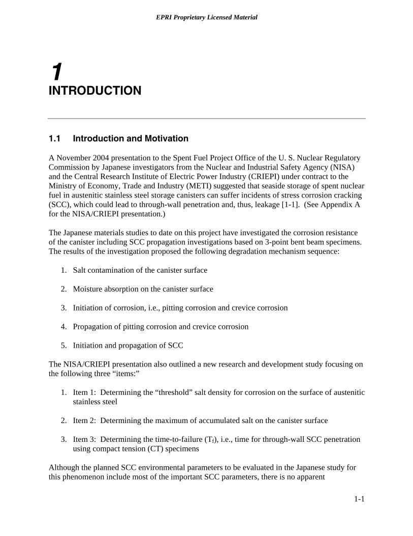
A November 2004 presentation to the Spent Fuel Project Office of the U. S. Nuclear Regulatory Commission by Japanese investigators from the Nuclear and Industrial Safety Agency (NISA) and the Central Research Institute of Electric Power Industry (CRIEPI) under contract to the Ministry of Economy, Trade and Industry (METI) suggested that seaside storage of spent nuclear fuel in austenitic stainless steel storage canisters can suffer incidents of stress corrosion cracking (SCC), which could lead to through-wall penetration and, thus, leakage [1-1]. (See Appendix A for the NISA/CRIEPI presentation.)
The Japanese materials studies to date on this project have investigated the corrosion resistance of the canister including SCC propagation investigations based on 3-point bent beam specimens. The results of the investigation proposed the following degradation mechanism sequence:
1. Salt contamination of the canister surface
2. Moisture absorption on the canister surface
3. Initiation of corrosion, i.e., pitting corrosion and crevice corrosion
4. Propagation of pitting corrosion and crevice corrosion
5. Initiation and propagation of SCC
The NISA/CRIEPI presentation also outlined a new research and development study focusing on the following three “items:”
1. Item 1: Determining the “threshold” salt density for corrosion on the surface of austenitic stainless steel
2. Item 2: Determining the maximum of accumulated salt on the canister surface
3. Item 3: Determining the time-to-failure (Tf), i.e., time for through-wall SCC penetration using compact tension (CT) specimens
Although the planned SCC environmental parameters to be evaluated in the Japanese study for this phenomenon include most of the important SCC parameters, there is no apparent
1-1
EPRI Proprietary Licensed Material Introduction
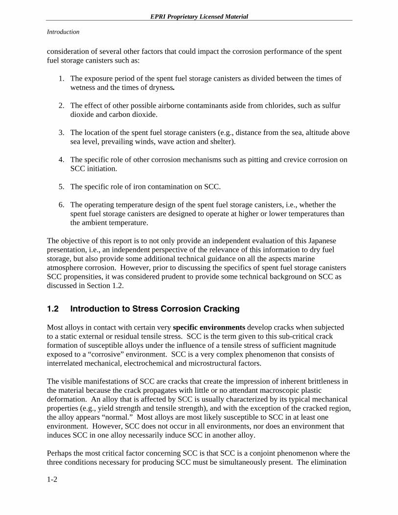
consideration of several other factors that could impact the corrosion performance of the spent fuel storage canisters such as:
1. The exposure period of the spent fuel storage canisters as divided between the times of wetness and the times of dryness.
2. The effect of other possible airborne contaminants aside from chlorides, such as sulfur dioxide and carbon dioxide.
3. The location of the spent fuel storage canisters (e.g., distance from the sea, altitude above sea level, prevailing winds, wave action and shelter).
4. The specific role of other corrosion mechanisms such as pitting and crevice corrosion on SCC initiation.
5. The specific role of iron contamination on SCC.
6. The operating temperature design of the spent fuel storage canisters, i.e., whether the spent fuel storage canisters are designed to operate at higher or lower temperatures than the ambient temperature.
The objective of this report is to not only provide an independent evaluation of this Japanese presentation, i.e., an independent perspective of the relevance of this information to dry fuel storage, but also provide some additional technical guidance on all the aspects marine atmosphere corrosion. However, prior to discussing the specifics of spent fuel storage canisters SCC propensities, it was considered prudent to provide some technical background on SCC as discussed in Section 1.2.
1.2 Introduction to Stress Corrosion Cracking
Most alloys in contact with certain very specific environments develop cracks when subjected to a static external or residual tensile stress. SCC is the term given to this sub-critical crack formation of susceptible alloys under the influence of a tensile stress of sufficient magnitude exposed to a “corrosive” environment. SCC is a very complex phenomenon that consists of interrelated mechanical, electrochemical and microstructural factors.
The visible manifestations of SCC are cracks that create the impression of inherent brittleness in the material because the crack propagates with little or no attendant macroscopic plastic deformation. An alloy that is affected by SCC is usually characterized by its typical mechanical properties (e.g., yield strength and tensile strength), and with the exception of the cracked region, the alloy appears “normal.” Most alloys are most likely susceptible to SCC in at least one environment. However, SCC does not occur in all environments, nor does an environment that induces SCC in one alloy necessarily induce SCC in another alloy.
Perhaps the most critical factor concerning SCC is that SCC is a conjoint phenomenon where the three conditions necessary for producing SCC must be simultaneously present. The elimination
1-2
EPRI Proprietary Licensed Material
Introduction
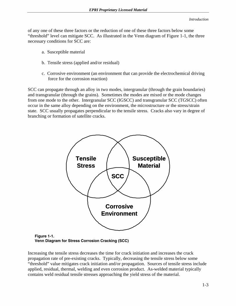
of any one of these three factors or the reduction of one of these three factors below some “threshold” level can mitigate SCC. As illustrated in the Venn diagram of Figure 1-1, the three necessary conditions for SCC are:
a. Susceptible material
b. Tensile stress (applied and/or residual)
c. Corrosive environment (an environment that can provide the electrochemical driving force for the corrosion reaction)
SCC can propagate through an alloy in two modes, intergranular (through the grain boundaries) and transgranular (through the grains). Sometimes the modes are mixed or the mode changes from one mode to the other. Intergranular SCC (IGSCC) and transgranular SCC (TGSCC) often occur in the same alloy depending on the environment, the microstructure or the stress/strain state. SCC usually propagates perpendicular to the tensile stress. Cracks also vary in degree of branching or formation of satellite cracks.
Tensile Stress
Susceptible Material
Corrosive Environment
SCC
Tensile Stress
Susceptible Material
Corrosive Environment
SCC
Figure 1-1. Venn Diagram for Stress Corrosion Cracking (SCC)
Increasing the tensile stress decreases the time for crack initiation and increases the crack propagation rate of pre-existing cracks. Typically, decreasing the tensile stress below some “threshold” value mitigates crack initiation and/or propagation. Sources of tensile stress include applied, residual, thermal, welding and even corrosion product. As-welded material typically contains weld residual tensile stresses approaching the yield stress of the material.
1-3
EPRI Proprietary Licensed Material Introduction
1.2.1 SCC Initiation and Propagation
Since the SCC mechanism consists of both crack initiation plus crack propagation, it is necessary to consider both steps in the SCC process. No crack growth can occur without crack initiation. While crack initiation and crack propagation are integrally linked processes in which the same fundamental processes give rise to both, i.e., the formation of a flaw of arbitrary dimensions (e.g., 50 µm [2 mils]) and the subsequent propagation of the flaw, crack initiation is the long step in the SCC phenomena [1-2]. The commonly used term “time to failure” (Tf) for SCC consists of the time to crack initiation plus the time for crack propagation, i.e.:
Tf = Tinitiation + Tpropagation
These processes include local strain that ruptures the protective oxide on passive alloys such as stainless steel and nickel-based alloys, repassivation kinetics of passive film reformation and liquid transport to create a crack tip chemistry described by the slip-oxidation model of SCC [1-2].
The rate-controlling step in the IGSCC process is crack initiation. Calculations have indicated that it takes 50% of the time to “failure” to nucleate an electrochemical stable crack of 0.01% of the wall thickness and another 30% of the time to “failure” to grow a crack to 1% of a component’s thickness [1-2].
Once a crack has been initiated, subsequent crack growth can be very rapid as a function of the material, stress and environmental parameters. It is important to note that the time to initiate a crack can be essentially “eliminated” by the existence of a pre-existing flaw in the component. For example, the pre-existence of a crevice due to a lack of full penetration in a nickel alloy weld essentially eliminates the time for crack initiation in an oxygenated high temperature water environment, i.e., the local crack environment already exists.
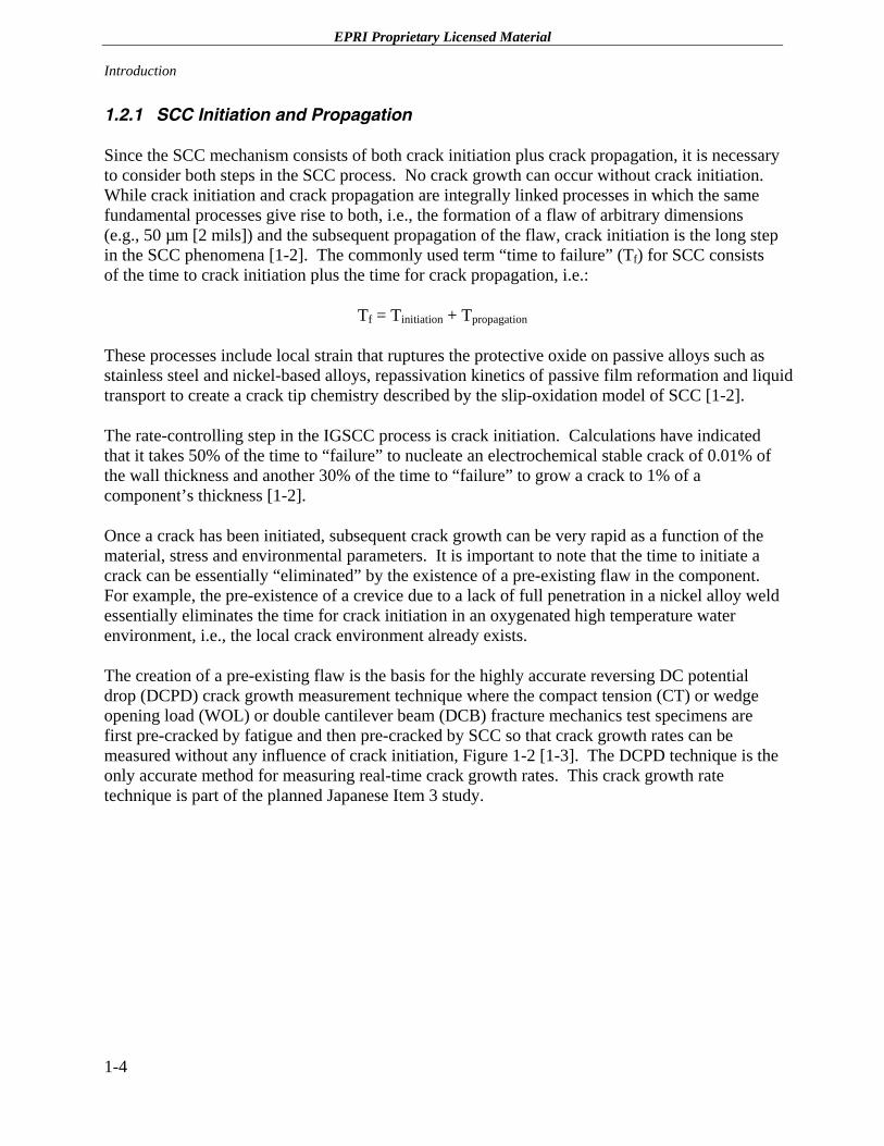
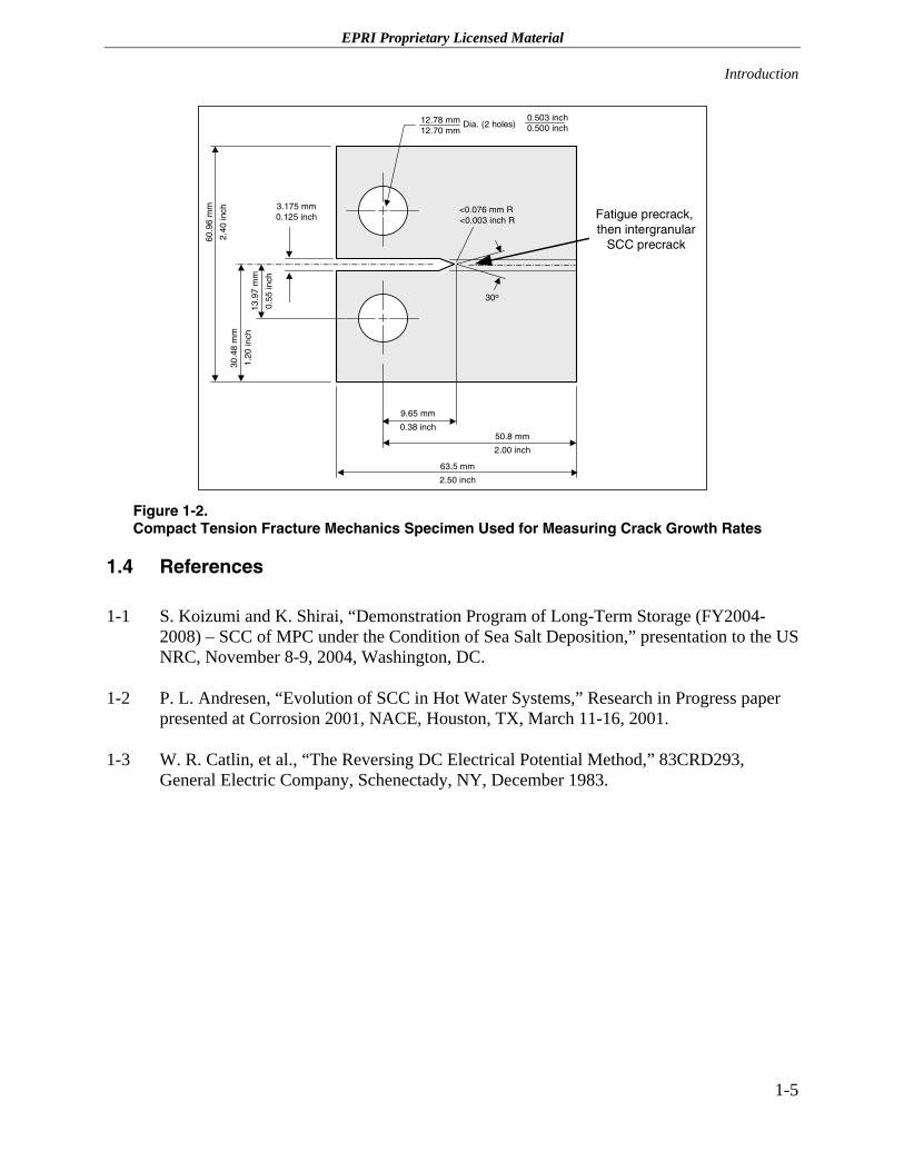
The creation of a pre-existing flaw is the basis for the highly accurate reversing DC potential drop (DCPD) crack growth measurement technique where the compact tension (CT) or wedge opening load (WOL) or double cantilever beam (DCB) fracture mechanics test specimens are first pre-cracked by fatigue and then pre-cracked by SCC so that crack growth rates can be measured without any influence of crack initiation, Figure 1-2 [1-3]. The DCPD technique is the only accurate method for measuring real-time crack growth rates. This crack growth rate technique is part of the planned Japanese Item 3 study.
1-4
EPRI Proprietary Licensed Material
Introduction
12.78 mm12.70 mm
Dia. (2 holes)
30o
<0.076 mm R <0.003 inch R
9.65 mm
0.38 inch50.8 mm
2.00 inch
63.5 mm
2.50 inch
30.4
8 m
m
1.20
inch
60.9
6 m
m
2.40
inch
13.9
7 m
m
0.55
inch
3.175 mm0.125 inch
0.503 inch0.500 inch
Fatigue precrack, then intergranular
SCC precrack
Figure 1-2. Compact Tension Fracture Mechanics Specimen Used for Measuring Crack Growth Rates
1.4 References
1-1 S. Koizumi and K. Shirai, “Demonstration Program of Long-Term Storage (FY2004-2008) – SCC of MPC under the Condition of Sea Salt Deposition,” presentation to the US NRC, November 8-9, 2004, Washington, DC.
1-2 P. L. Andresen, “Evolution of SCC in Hot Water Systems,” Research in Progress paper presented at Corrosion 2001, NACE, Houston, TX, March 11-16, 2001.
1-3 W. R. Catlin, et al., “The Reversing DC Electrical Potential Method,” 83CRD293, General Electric Company, Schenectady, NY, December 1983.
1-5

EPRI Proprietary Licensed Material
2 MARINE ATMOSPHERE CORROSION PARAMETERS
2.1 Background
Atmospheric corrosion can be defined as the corrosion of materials exposed to air and its contaminants rather than immersed in an aqueous solution. While the marine-industrial atmosphere is generally considered to be the most aggressive atmospheric corrosion environment, the marine environment is ranked a close second in corrosivity. The factors that influence marine atmospheric corrosion include moisture and time of wetness, temperature, material composition, airborne contaminants (e.g., chlorides, sulfur dioxide, carbon dioxide, etc.) and solar radiation. The location, i.e., the proximity to the ocean, elevation above sea level, sunlight, prevailing winds and wave action, shelter of a component, also has a very strong influence on corrosion behavior. These factors will be discussed in the following subsections of this report.
2.2 Moisture and Time of Wetness
Corrosion in any aqueous solution can occur if, and only if, the corrosion system consists of an anode, cathode, an electrolyte and an electrical circuit. While the anode, cathode and electrical circuit typically coexist on the surface of the corroding metal itself, the electrolyte is a separate fundamental factor. The electrolyte is a solution that will allow a current to pass through it by the transport of anions and cations. Water that contains ions is an excellent electrolyte. Therefore, the amount and availability of water or moisture present is an extremely important factor in atmospheric corrosion.
Thin film electrolytes tend to form on metallic surfaces under atmospheric condition after a certain critical humidity level is obtained [2-1]. In the case of a completely uncontaminated atmosphere, a perfectly clean metal surface would not be expected to experience a corrosion reaction at a relative humidity of <100%. However, due to the presence of hygroscopic surface species, impurities in the atmosphere and small temperature gradients between the atmosphere and metallic surfaces, a microscopic surface electrolyte tends to form at significantly lower humidity levels [2-1]. For example, the corrosion of iron and carbon steels increase dramatically above a relative humidity of 60% in an atmosphere free of sulfur dioxide [2-1 to 2-3]. However, this critical 60% relative humidity is not a fixed “threshold.” The critical relative humidity for corrosion is a function of the hygroscopicity of the corrosion products, salts and airborne contaminants.
A measure of the effect of moisture is the time of wetness, which is strongly dependent on the critical relative humidity. Corrosion increases with time of wetness, i.e., time in contact with an
2-1
EPRI Proprietary Licensed Material Marine Atmosphere Corrosion Parameters
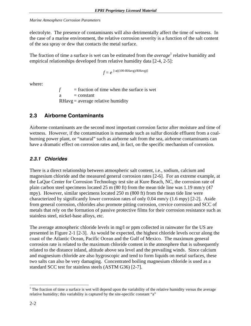
electrolyte. The presence of contaminants will also detrimentally affect the time of wetness. In the case of a marine environment, the relative corrosion severity is a function of the salt content of the sea spray or dew that contacts the metal surface.
The fraction of time a surface is wet can be estimated from the average1 relative humidity and empirical relationships developed from relative humidity data [2-4, 2-5]:
f = e [-a((100-RHavg)/RHavg)]
where: f = fraction of time when the surface is wet a = constant RHavg = average relative humidity
2.3 Airborne Contaminants
Airborne contaminants are the second most important corrosion factor after moisture and time of wetness. However, if the contamination is manmade such as sulfur dioxide effluent from a coal-burning power plant, or “natural” such as airborne salt from the sea, airborne contaminants can have a dramatic effect on corrosion rates and, in fact, on the specific mechanism of corrosion.
2.3.1 Chlorides
There is a direct relationship between atmospheric salt content, i.e., sodium, calcium and magnesium chloride and the measured general corrosion rates [2-6]. For an extreme example, at the LaQue Center for Corrosion Technology test site at Kure Beach, NC, the corrosion rate of plain carbon steel specimens located 25 m (80 ft) from the mean tide line was 1.19 mm/y (47 mpy). However, similar specimens located 250 m (800 ft) from the mean tide line were characterized by significantly lower corrosion rates of only 0.04 mm/y (1.6 mpy) [2-2]. Aside from general corrosion, chlorides also promote pitting corrosion, crevice corrosion and SCC of metals that rely on the formation of passive protective films for their corrosion resistance such as stainless steel, nickel-base alloys, etc.
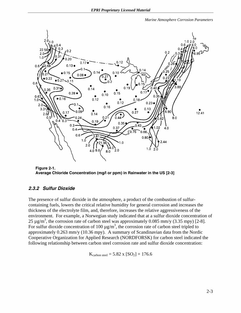
The average atmospheric chloride levels in mg/l or ppm collected in rainwater for the US are presented in Figure 2-1 [2-3]. As would be expected, the highest chloride levels occur along the coast of the Atlantic Ocean, Pacific Ocean and the Gulf of Mexico. The maximum general corrosion rate is related to the maximum chloride content in the atmosphere that is subsequently related to the distance inland, altitude above sea level and the prevailing winds. Since calcium and magnesium chloride are also hygroscopic and tend to form liquids on metal surfaces, these two salts can also be very damaging. Concentrated boiling magnesium chloride is used as a standard SCC test for stainless steels (ASTM G36) [2-7].
1 The fraction of time a surface is wet will depend upon the variability of the relative humidity versus the average relative humidity; this variability is captured by the site-specific constant “a”
2-2
EPRI Proprietary Licensed Material
Marine Atmosphere Corrosion Parameters
Figure 2-1. Average Chloride Concentration (mg/l or ppm) in Rainwater in the US [2-3]
2.3.2 Sulfur Dioxide
The presence of sulfur dioxide in the atmosphere, a product of the combustion of sulfur-containing fuels, lowers the critical relative humidity for general corrosion and increases the thickness of the electrolyte film, and, therefore, increases the relative aggressiveness of the environment. For example, a Norwegian study indicated that at a sulfur dioxide concentration of 25 µg/m3, the corrosion rate of carbon steel was approximately 0.085 mm/y (3.35 mpy) [2-8]. For sulfur dioxide concentration of 100 µg/m3, the corrosion rate of carbon steel tripled to approximately 0.263 mm/y (10.36 mpy). A summary of Scandinavian data from the Nordic Cooperative Organization for Applied Research (NORDFORSK) for carbon steel indicated the following relationship between carbon steel corrosion rate and sulfur dioxide concentration:
Kcarbon steel = 5.82 x [SO2] + 176.6
2-3
EPRI Proprietary Licensed Material Marine Atmosphere Corrosion Parameters
where: Kcarbon steel = general corrosion rate of carbon steel in g/(m2
*y) 2 [SO2] = concentration of sulfur dioxide in µg/m3
One of the reasons for the aggressiveness of sulfur dioxide is the formation of sulfurous acid in the presence of water as follows:
SO2 + H2O = H+ + HSO3-
A multiple linear regression analysis to account for chloride, acidity and days of precipitation revealed the following equation for atmospheric corrosion in Norway:
Kcarbon steel = 1.54 x [SO2] + 2.34 x DPREC + 0.05 H+ - 15.2
where: Kcarbon steel = general corrosion rate of carbon steel in g/(m2
*month) 3 [SO2] = concentration of sulfur dioxide in µg/m3
DPREC = days with precipitation H+ = concentration of strong acid in precipitation (µ-equivalent H+/liter)
It should be noted that both these equations are based of data obtained during this particular investigation, i.e., after the fact. It would be significantly more difficult to predict future corrosion performance from these equations since parameters such as days with precipitation are difficult to estimate accurately. However, based on historical data, an accuracy of ± 20% can be obtained [2-8].
2.3.3 Carbon Dioxide
Carbon dioxide also has an effect on the corrosion rate of some alloys due to the formation of carbonic acid that forms in the presence of water as follows:
CO2 + H2O = H+ + HCO3-
A pH of 5.6 can be easily achieved with atmospheric carbon dioxide in equilibrium with high purity water. Carbonates are found in the corrosion products on a number of metals exposed to the atmosphere [2-2]. However, the presence of carbonates can mitigate the corrosive effects of sulfur dioxide. Overall, carbon dioxide does not have the dramatic effect on corrosion as either chloride, or sulfur dioxide.
2 To convert from g/(m2
*y) to mpy (carbon steel), multiply by 0.005; and to convert from g/(m2*y) to mm/y (carbon
steel), multiply by 1.27 x 10⁻⁴
3 To convert from g/(m2*month) to mpy (carbon steel), multiply by 0.06; and to convert from g/(m2
*month) to mm/y (carbon steel), multiply by 1.5 x 10⁻³
2-4
EPRI Proprietary Licensed Material
Marine Atmosphere Corrosion Parameters
2.4 Distance, Elevation, Orientation and Shelter
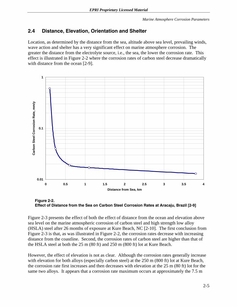
Location, as determined by the distance from the sea, altitude above sea level, prevailing winds, wave action and shelter has a very significant effect on marine atmosphere corrosion. The greater the distance from the electrolyte source, i.e., the sea, the lower the corrosion rate. This effect is illustrated in Figure 2-2 where the corrosion rates of carbon steel decrease dramatically with distance from the ocean [2-9].
0.01
0.1
1
0 0.5 1 1.5 2 2.5 3 3.5Distance from Sea, km
Car
bon
Stee
l Cor
rosi
on R
ate,
mm
/y
4
Figure 2-2. Effect of Distance from the Sea on Carbon Steel Corrosion Rates at Aracaju, Brazil [2-9]
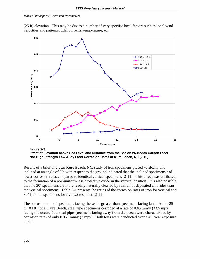
Figure 2-3 presents the effect of both the effect of distance from the ocean and elevation above sea level on the marine atmospheric corrosion of carbon steel and high strength low alloy (HSLA) steel after 26 months of exposure at Kure Beach, NC [2-10]. The first conclusion from Figure 2-3 is that, as was illustrated in Figure 2-2, the corrosion rates decrease with increasing distance from the coastline. Second, the corrosion rates of carbon steel are higher than that of the HSLA steel at both the 25 m (80 ft) and 250 m (800 ft) lot at Kure Beach.
However, the effect of elevation is not as clear. Although the corrosion rates generally increase with elevation for both alloys (especially carbon steel) at the 250 m (800 ft) lot at Kure Beach, the corrosion rate first increases and then decreases with elevation at the 25 m (80 ft) lot for the same two alloys. It appears that a corrosion rate maximum occurs at approximately the 7.5 m
2-5
EPRI Proprietary Licensed Material Marine Atmosphere Corrosion Parameters
(25 ft) elevation. This may be due to a number of very specific local factors such as local wind velocities and patterns, tidal currents, temperature, etc.
0
0.1
0.2
0.3
0.4
0.5
0.6
4 6 8 10 12 14 16 18Elevation, m
Cor
rosi
on R
ate,
mm
/y
250 m HSLA
250 m CS
25 m HSLA
25 m CS
Figure 2-3. Effect of Elevation above Sea Level and Distance from the Sea on 26-month Carbon Steel and High Strength Low Alloy Steel Corrosion Rates at Kure Beach, NC [2-10]
Results of a brief one-year Kure Beach, NC, study of iron specimens placed vertically and inclined at an angle of 30º with respect to the ground indicated that the inclined specimens had lower corrosion rates compared to identical vertical specimens [2-11]. This effect was attributed to the formation of a non-uniform less protective oxide in the vertical position. It is also possible that the 30º specimens are more readily naturally cleaned by rainfall of deposited chlorides than the vertical specimens. Table 2-1 presents the ratios of the corrosion rates of iron for vertical and 30º inclined specimens for five US test sites [2-11].
The corrosion rate of specimens facing the sea is greater than specimens facing land. At the 25 m (80 ft) lot at Kure Beach, steel pipe specimens corroded at a rate of 0.85 mm/y (33.5 mpy) facing the ocean. Identical pipe specimens facing away from the ocean were characterized by corrosion rates of only 0.051 mm/y (2 mpy). Both tests were conducted over a 4.5 year exposure period.
2-6
EPRI Proprietary Licensed Material
Marine Atmosphere Corrosion Parameters
Table 2-1 Comparison of Iron Atmospheric Corrosion Rates for Vertical and 30º Inclined Specimens [2-11]
Location Corrosion Rate Ratio, vertical/30º
Kearny, NJ 1.25
Vandergrift, PA 1.26
South Bend, PA 1.20
25 m lot (80 ft.), Kure Beach, NC 1.41
250 m lot (800 ft.), Kure Beach, NC 1.25
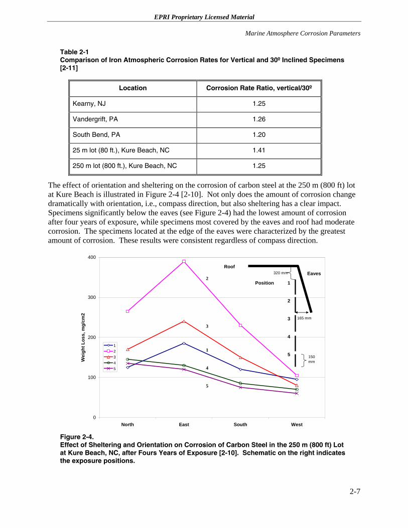
The effect of orientation and sheltering on the corrosion of carbon steel at the 250 m (800 ft) lot at Kure Beach is illustrated in Figure 2-4 [2-10]. Not only does the amount of corrosion change dramatically with orientation, i.e., compass direction, but also sheltering has a clear impact. Specimens significantly below the eaves (see Figure 2-4) had the lowest amount of corrosion after four years of exposure, while specimens most covered by the eaves and roof had moderate corrosion. The specimens located at the edge of the eaves were characterized by the greatest amount of corrosion. These results were consistent regardless of compass direction.
0
100
200
300
400
North East South West
Wei
ght L
oss,
mg/
cm2
12345
1
2
3
4
5
RoofEaves
2
3
1
4
5
Position
150 mm
165 mm
320 mm
Figure 2-4. Effect of Sheltering and Orientation on Corrosion of Carbon Steel in the 250 m (800 ft) Lot at Kure Beach, NC, after Fours Years of Exposure [2-10]. Schematic on the right indicates the exposure positions.
2-7
EPRI Proprietary Licensed Material Marine Atmosphere Corrosion Parameters
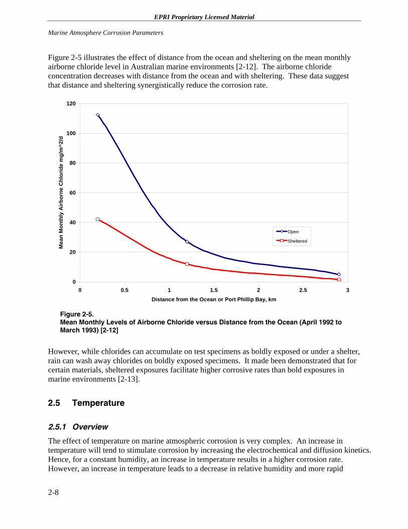
Figure 2-5 illustrates the effect of distance from the ocean and sheltering on the mean monthly airborne chloride level in Australian marine environments [2-12]. The airborne chloride concentration decreases with distance from the ocean and with sheltering. These data suggest that distance and sheltering synergistically reduce the corrosion rate.
0
20
40
60
80
100
120
0 0.5 1 1.5 2 2.5Distance from the Ocean or Port Phillip Bay, km
Mea
n M
onth
ly A
irbor
ne C
hlor
ide
mg/
m^2
/d
3
Open
Sheltered
Figure 2-5. Mean Monthly Levels of Airborne Chloride versus Distance from the Ocean (April 1992 to March 1993) [2-12]
However, while chlorides can accumulate on test specimens as boldly exposed or under a shelter, rain can wash away chlorides on boldly exposed specimens. It made been demonstrated that for certain materials, sheltered exposures facilitate higher corrosive rates than bold exposures in marine environments [2-13].
2.5 Temperature
2.5.1 Overview
The effect of temperature on marine atmospheric corrosion is very complex. An increase in temperature will tend to stimulate corrosion by increasing the electrochemical and diffusion kinetics. Hence, for a constant humidity, an increase in temperature results in a higher corrosion rate. However, an increase in temperature leads to a decrease in relative humidity and more rapid
2-8
EPRI Proprietary Licensed Material
Marine Atmosphere Corrosion Parameters
evaporation of the surface electrolyte and a decrease in the long-term corrosion rate. An increase in temperature will also significantly reduce the amount of dissolved oxygen in the water on the metal surface and, thus, the corrosion potential of the metal in an environment.
The temperature of interest for atmospheric corrosion is typically not the average daily temperature, but rather the dew point temperature of the component. Obviously, dry hot conditions are preferable to cooler moist conditions. Therefore, since temperature affects the relative humidity, dew point, time of wetness, dissolved oxygen content in the water, corrosion potential and, thus, the kinetics of all corrosion reactions, it is not possible to identify the effect of temperature on marine atmospheric corrosion.
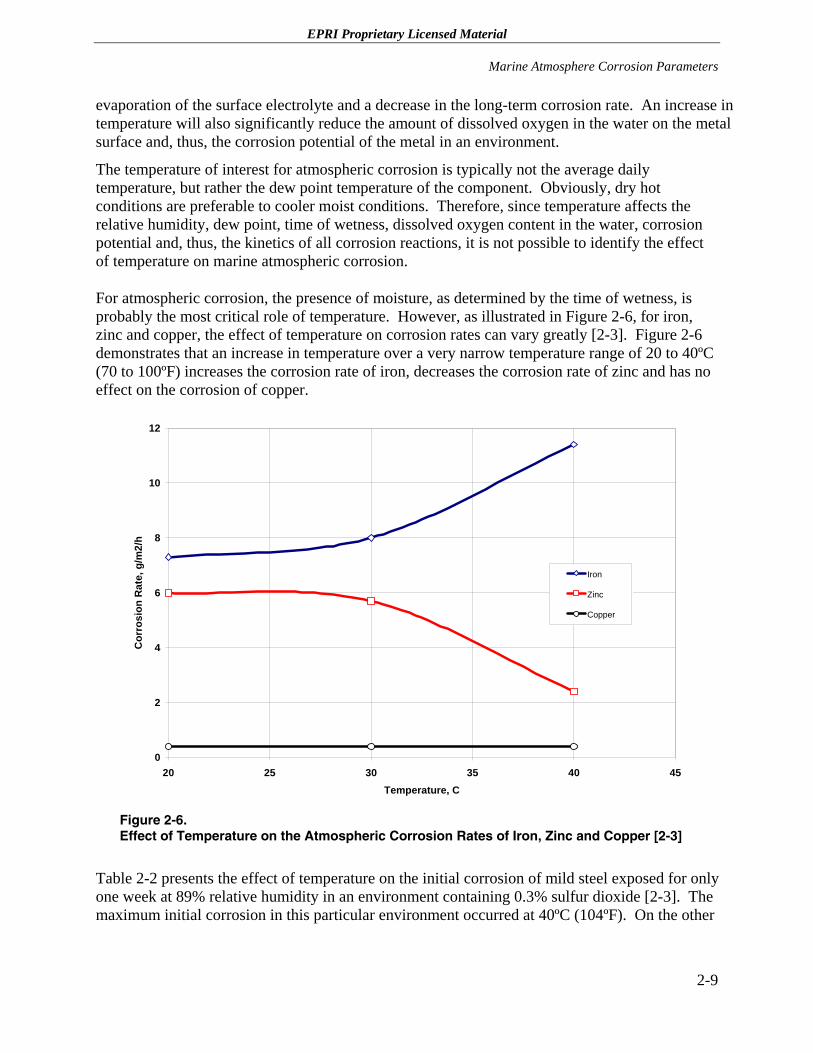
For atmospheric corrosion, the presence of moisture, as determined by the time of wetness, is probably the most critical role of temperature. However, as illustrated in Figure 2-6, for iron, zinc and copper, the effect of temperature on corrosion rates can vary greatly [2-3]. Figure 2-6 demonstrates that an increase in temperature over a very narrow temperature range of 20 to 40ºC (70 to 100ºF) increases the corrosion rate of iron, decreases the corrosion rate of zinc and has no effect on the corrosion of copper.
0
2
4
6
8
10
12
20 25 30 35 40 45Temperature, C
Cor
rosi
on R
ate,
g/m
2/h
Iron
Zinc
Copper
Figure 2-6. Effect of Temperature on the Atmospheric Corrosion Rates of Iron, Zinc and Copper [2-3]
Table 2-2 presents the effect of temperature on the initial corrosion of mild steel exposed for only one week at 89% relative humidity in an environment containing 0.3% sulfur dioxide [2-3]. The maximum initial corrosion in this particular environment occurred at 40ºC (104ºF). On the other
2-9
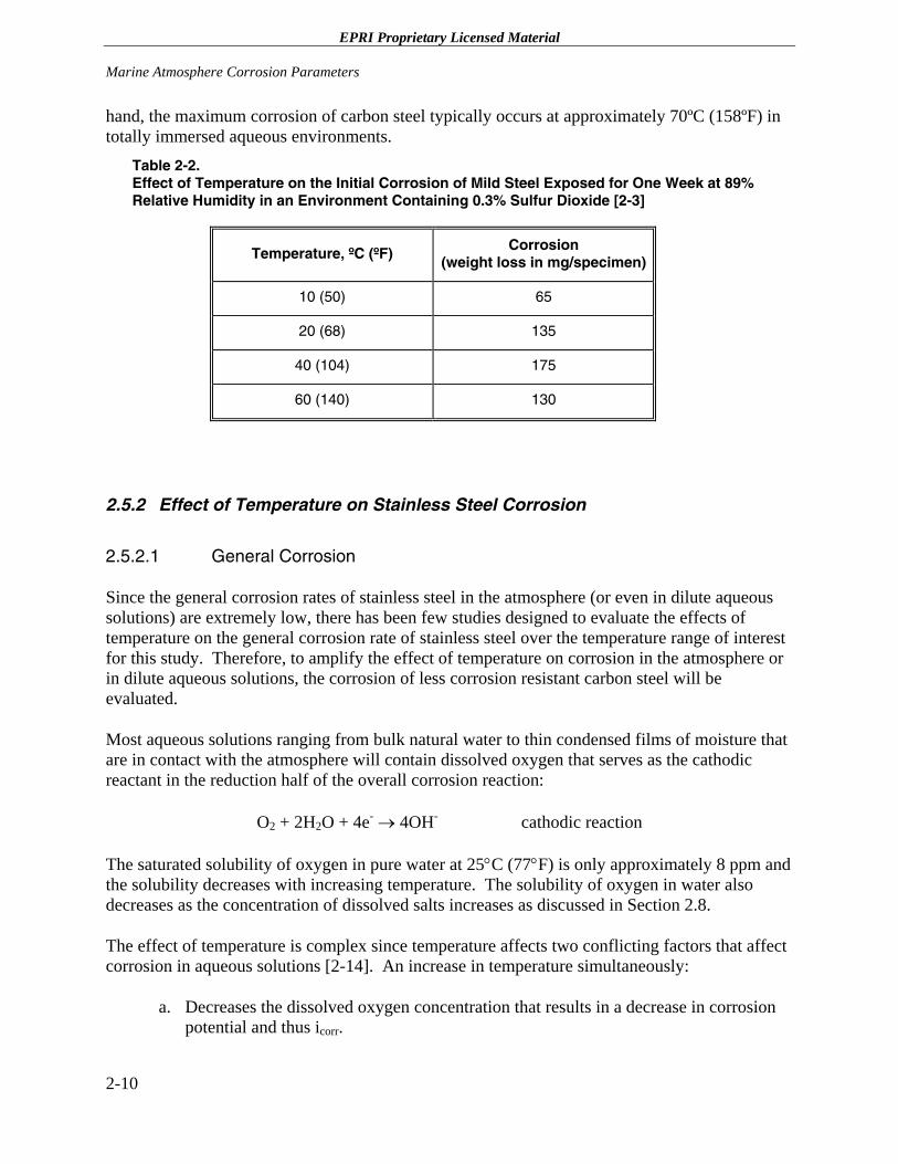
EPRI Proprietary Licensed Material Marine Atmosphere Corrosion Parameters
hand, the maximum corrosion of carbon steel typically occurs at approximately 70ºC (158ºF) in totally immersed aqueous environments.
Table 2-2. Effect of Temperature on the Initial Corrosion of Mild Steel Exposed for One Week at 89% Relative Humidity in an Environment Containing 0.3% Sulfur Dioxide [2-3]
Temperature, ºC (ºF) Corrosion (weight loss in mg/specimen)
10 (50) 65
20 (68) 135
40 (104) 175
60 (140) 130
2.5.2 Effect of Temperature on Stainless Steel Corrosion
2.5.2.1 General Corrosion
Since the general corrosion rates of stainless steel in the atmosphere (or even in dilute aqueous solutions) are extremely low, there has been few studies designed to evaluate the effects of temperature on the general corrosion rate of stainless steel over the temperature range of interest for this study. Therefore, to amplify the effect of temperature on corrosion in the atmosphere or in dilute aqueous solutions, the corrosion of less corrosion resistant carbon steel will be evaluated.
Most aqueous solutions ranging from bulk natural water to thin condensed films of moisture that are in contact with the atmosphere will contain dissolved oxygen that serves as the cathodic reactant in the reduction half of the overall corrosion reaction:
O2 + 2H2O + 4e- → 4OH- cathodic reaction
The saturated solubility of oxygen in pure water at 25°C (77°F) is only approximately 8 ppm and the solubility decreases with increasing temperature. The solubility of oxygen in water also decreases as the concentration of dissolved salts increases as discussed in Section 2.8.
The effect of temperature is complex since temperature affects two conflicting factors that affect corrosion in aqueous solutions [2-14]. An increase in temperature simultaneously:
a. Decreases the dissolved oxygen concentration that results in a decrease in corrosion potential and thus icorr.
2-10
EPRI Proprietary Licensed Material
Marine Atmosphere Corrosion Parameters
b. Increases the oxygen diffusion coefficient, which increases approximately 3% per °C increase in temperature.
Although data are scarce for these conflicting effects, the net mass transport of oxygen increases with temperature until a maximum is reached where the concentration of dissolved oxygen decreases as the boiling point is approached [2-15].
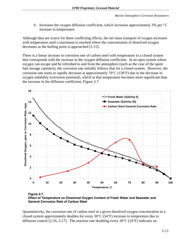
There is a linear increase in corrosion rate of carbon steel with temperature in a closed system that corresponds with the increase in the oxygen diffusion coefficient. In an open system where oxygen can escape and be refreshed to and from the atmosphere (such as the case of the spent fuel storage canisters), the corrosion rate initially follows that for a closed system. However, the corrosion rate starts to rapidly decrease at approximately 70°C (158°F) due to the decrease in oxygen solubility (corrosion potential), which at that temperature becomes more significant than the increase in the diffusion coefficient, Figure 2-7.
0
2
4
6
8
10
12
14
16
0 10 20 30 40 50 60 70 80 90 1Temperature, C
Dis
solv
ed O
xyge
n, p
pm o
r Cor
rosi
on R
ate,
mpy
00
Fresh Water (Salinity 0)Seawater (Salinity 35)Carbon Steel General Corrosion Rate
Figure 2-7. Effect of Temperature on Dissolved Oxygen Content of Fresh Water and Seawater and General Corrosion Rate of Carbon Steel
Quantitatively, the corrosion rate of carbon steel at a given dissolved oxygen concentration in a closed system approximately doubles for every 30°C (54°F) increase in temperature due to diffusion control [2-16, 2-17]. The reaction rate doubling every 30°C (54°F) indicates an
2-11
EPRI Proprietary Licensed Material Marine Atmosphere Corrosion Parameters
activation energy of 3000 to 4000 cal/mole. This low value suggests that the corrosion process is controlled by the diffusion of oxygen. (Note that the formation of more protective oxide films that usually occurs at higher temperatures is not considered in any thermal activation evaluation.)
Although the presence of impurities in the water such as sulfate and chloride increase the corrosion rate of carbon steel in open systems [2-18 to 2-20], the effect of temperature on corrosion is the same. That is, the corrosion rate rapidly decreases as the elevated boiling point is approached. This same type of temperature effect would also be anticipated for stainless steel in open systems; however, the absolute values of the general corrosion rates for stainless steel are so extremely low that essentially no general corrosion data for austenitic stainless steels could be found; therefore, the effect of temperature could not be quantified,
2.5.2.2 Effects of Temperature on Pitting and Crevice Corrosion
Stainless steel is corrosion resistant only because of its passive film, which is a very thin (nm scale) oxide layer that forms naturally on its surface. Such passive films, however, are often susceptible to localized breakdown resulting in accelerated dissolution of the underlying metal. If the attack initiates on an open surface, it is called pitting corrosion. If the attack occurs at an occluded site it is called crevice corrosion. These closely related forms of localized corrosion can lead to accelerated failure of structural components by perforation, or by acting as an initiation site for SCC.
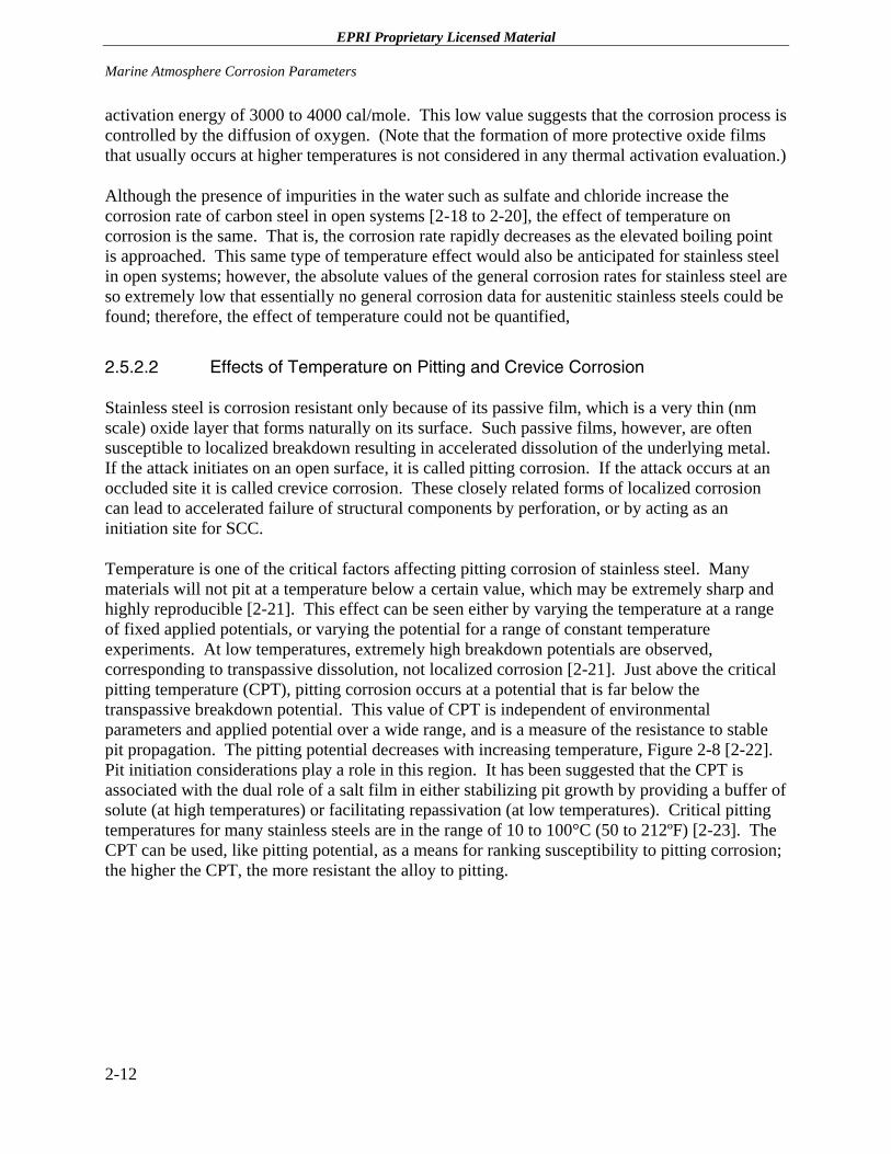
Temperature is one of the critical factors affecting pitting corrosion of stainless steel. Many materials will not pit at a temperature below a certain value, which may be extremely sharp and highly reproducible [2-21]. This effect can be seen either by varying the temperature at a range of fixed applied potentials, or varying the potential for a range of constant temperature experiments. At low temperatures, extremely high breakdown potentials are observed, corresponding to transpassive dissolution, not localized corrosion [2-21]. Just above the critical pitting temperature (CPT), pitting corrosion occurs at a potential that is far below the transpassive breakdown potential. This value of CPT is independent of environmental parameters and applied potential over a wide range, and is a measure of the resistance to stable pit propagation. The pitting potential decreases with increasing temperature, Figure 2-8 [2-22]. Pit initiation considerations play a role in this region. It has been suggested that the CPT is associated with the dual role of a salt film in either stabilizing pit growth by providing a buffer of solute (at high temperatures) or facilitating repassivation (at low temperatures). Critical pitting temperatures for many stainless steels are in the range of 10 to 100°C (50 to 212ºF) [2-23]. The CPT can be used, like pitting potential, as a means for ranking susceptibility to pitting corrosion; the higher the CPT, the more resistant the alloy to pitting.
2-12
EPRI Proprietary Licensed Material
Marine Atmosphere Corrosion Parameters
Figure 2-8. Effect of Temperature on the Pitting Potential of Stainless Steel in a 3% NaCl Solution [2-22]
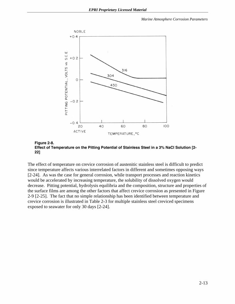
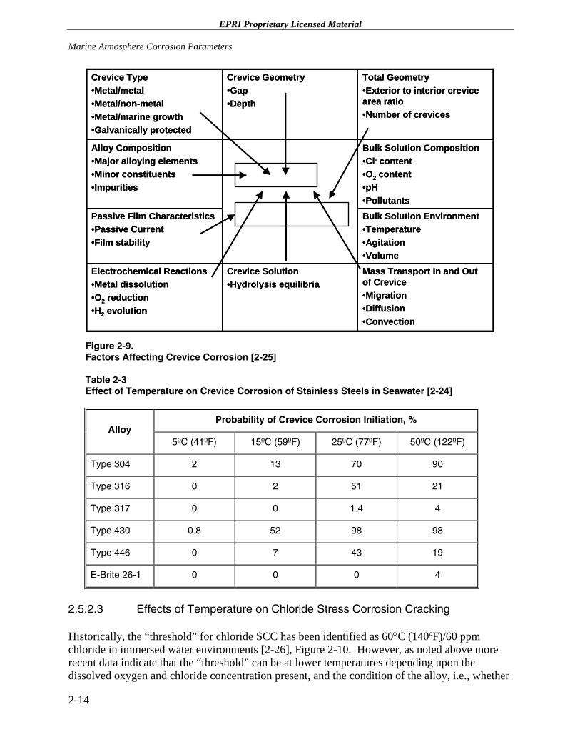
The effect of temperature on crevice corrosion of austenitic stainless steel is difficult to predict since temperature affects various interrelated factors in different and sometimes opposing ways [2-24]. As was the case for general corrosion, while transport processes and reaction kinetics would be accelerated by increasing temperature, the solubility of dissolved oxygen would decrease. Pitting potential, hydrolysis equilibria and the composition, structure and properties of the surface films are among the other factors that affect crevice corrosion as presented in Figure 2-9 [2-25]. The fact that no simple relationship has been identified between temperature and crevice corrosion is illustrated in Table 2-3 for multiple stainless steel creviced specimens exposed to seawater for only 30 days [2-24].
2-13
EPRI Proprietary Licensed Material Marine Atmosphere Corrosion Parameters
Mass Transport In and Out of Crevice•Migration•Diffusion•Convection
Crevice Solution•Hydrolysis equilibria
Electrochemical Reactions•Metal dissolution•O2 reduction•H2 evolution
Bulk Solution Environment•Temperature•Agitation•Volume
Passive Film Characteristics•Passive Current•Film stability
Bulk Solution Composition•Cl- content•O2 content•pH•Pollutants
Alloy Composition•Major alloying elements•Minor constituents•Impurities
Total Geometry•Exterior to interior crevice area ratio•Number of crevices
Crevice Geometry•Gap•Depth
Crevice Type•Metal/metal•Metal/non-metal•Metal/marine growth•Galvanically protected
Figure 2-9. Factors Affecting Crevice Corrosion [2-25]
Table 2-3 Effect of Temperature on Crevice Corrosion of Stainless Steels in Seawater [2-24]
Probability of Crevice Corrosion Initiation, % Alloy
5ºC (41ºF) 15ºC (59ºF) 25ºC (77ºF) 50ºC (122ºF)
Type 304 2 13 70 90
Type 316 0 2 51 21
Type 317 0 0 1.4 4
Type 430 0.8 52 98 98
Type 446 0 7 43 19
E-Brite 26-1 0 0 0 4
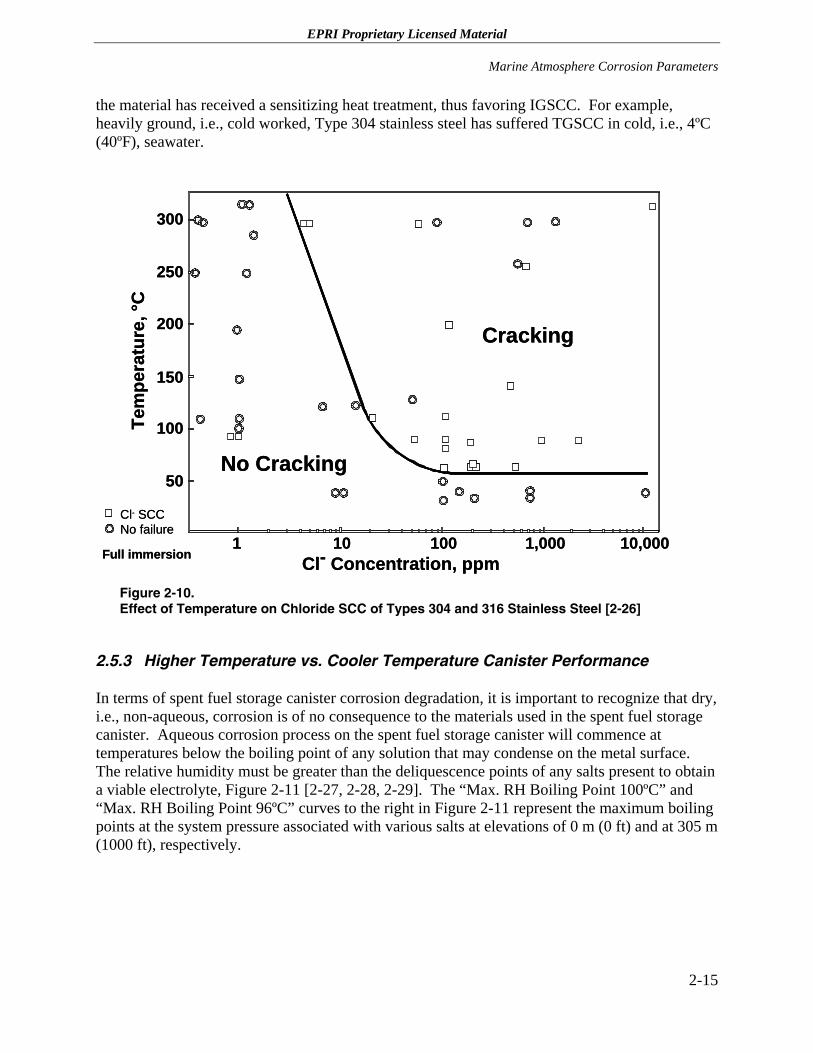
2.5.2.3 Effects of Temperature on Chloride Stress Corrosion Cracking
Historically, the “threshold” for chloride SCC has been identified as 60°C (140ºF)/60 ppm chloride in immersed water environments [2-26], Figure 2-10. However, as noted above more recent data indicate that the “threshold” can be at lower temperatures depending upon the dissolved oxygen and chloride concentration present, and the condition of the alloy, i.e., whether
2-14
EPRI Proprietary Licensed Material
Marine Atmosphere Corrosion Parameters
the material has received a sensitizing heat treatment, thus favoring IGSCC. For example, heavily ground, i.e., cold worked, Type 304 stainless steel has suffered TGSCC in cold, i.e., 4ºC (40ºF), seawater.
1 100 1,000 10,00010
50
100
150
200
250
300
Cracking
No Cracking
Tem
pera
ture
, °C
Cl- Concentration, ppmFull immersion
Cl- SCCNo failure
1 100 1,000 10,00010
50
100
150
200
250
300
Cracking
No Cracking
Tem
pera
ture
, °C
Cl- Concentration, ppmFull immersion
Cl- SCCNo failure
Figure 2-10. Effect of Temperature on Chloride SCC of Types 304 and 316 Stainless Steel [2-26]
2.5.3 Higher Temperature vs. Cooler Temperature Canister Performance
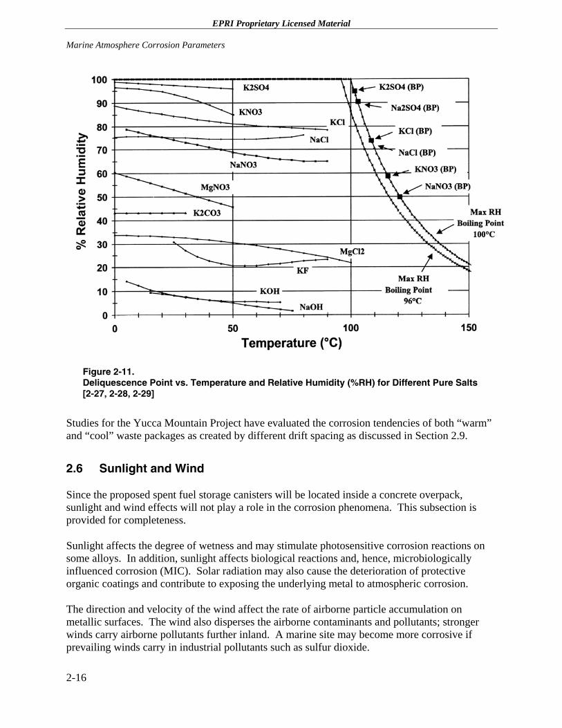
In terms of spent fuel storage canister corrosion degradation, it is important to recognize that dry, i.e., non-aqueous, corrosion is of no consequence to the materials used in the spent fuel storage canister. Aqueous corrosion process on the spent fuel storage canister will commence at temperatures below the boiling point of any solution that may condense on the metal surface. The relative humidity must be greater than the deliquescence points of any salts present to obtain a viable electrolyte, Figure 2-11 [2-27, 2-28, 2-29]. The “Max. RH Boiling Point 100ºC” and “Max. RH Boiling Point 96ºC” curves to the right in Figure 2-11 represent the maximum boiling points at the system pressure associated with various salts at elevations of 0 m (0 ft) and at 305 m (1000 ft), respectively.
2-15
EPRI Proprietary Licensed Material Marine Atmosphere Corrosion Parameters
Figure 2-11. Deliquescence Point vs. Temperature and Relative Humidity (%RH) for Different Pure Salts [2-27, 2-28, 2-29]
Studies for the Yucca Mountain Project have evaluated the corrosion tendencies of both “warm” and “cool” waste packages as created by different drift spacing as discussed in Section 2.9.
2.6 Sunlight and Wind
Since the proposed spent fuel storage canisters will be located inside a concrete overpack, sunlight and wind effects will not play a role in the corrosion phenomena. This subsection is provided for completeness.
Sunlight affects the degree of wetness and may stimulate photosensitive corrosion reactions on some alloys. In addition, sunlight affects biological reactions and, hence, microbiologically influenced corrosion (MIC). Solar radiation may also cause the deterioration of protective organic coatings and contribute to exposing the underlying metal to atmospheric corrosion.
The direction and velocity of the wind affect the rate of airborne particle accumulation on metallic surfaces. The wind also disperses the airborne contaminants and pollutants; stronger winds carry airborne pollutants further inland. A marine site may become more corrosive if prevailing winds carry in industrial pollutants such as sulfur dioxide.
2-16
EPRI Proprietary Licensed Material
Marine Atmosphere Corrosion Parameters
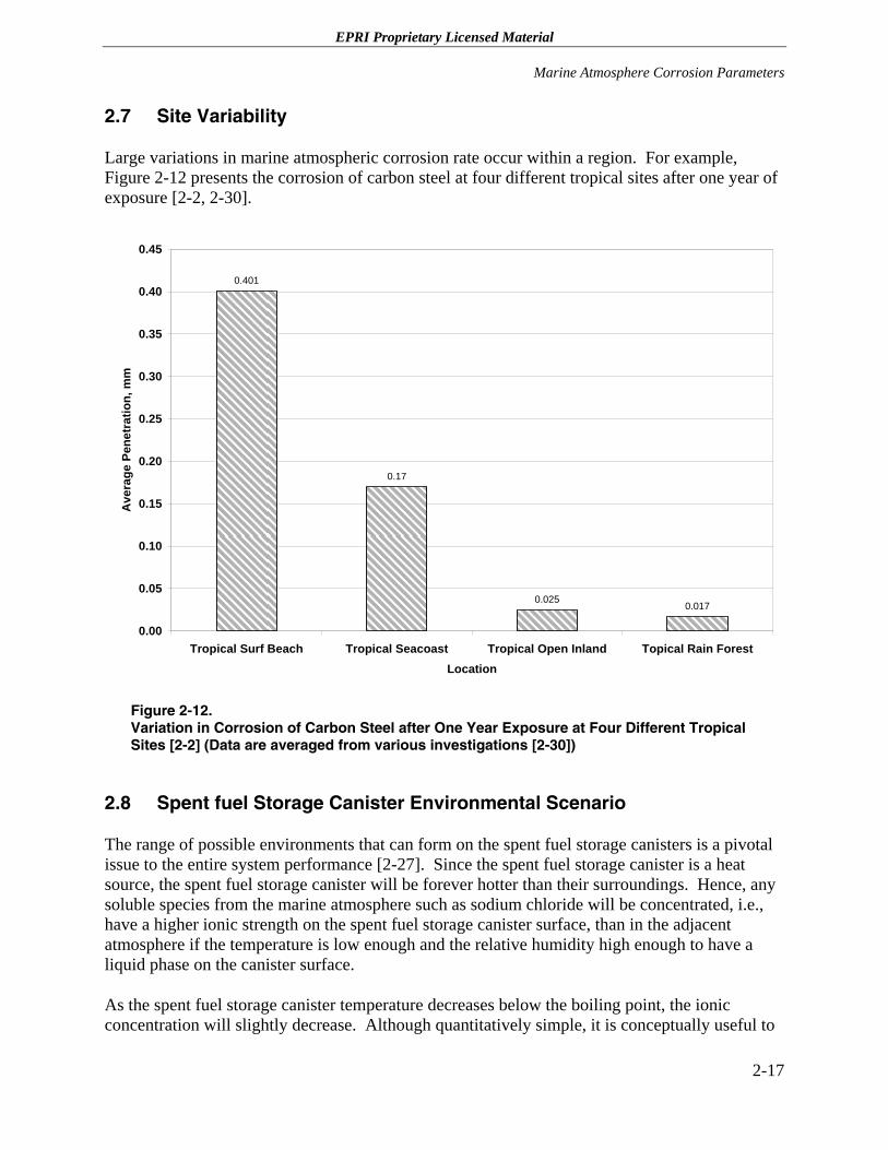
2.7 Site Variability
Large variations in marine atmospheric corrosion rate occur within a region. For example, Figure 2-12 presents the corrosion of carbon steel at four different tropical sites after one year of exposure [2-2, 2-30].
0.401
0.17
0.0250.017
0.00
0.05
0.10
0.15
0.20
0.25
0.30
0.35
0.40
0.45
Tropical Surf Beach Tropical Seacoast Tropical Open Inland Topical Rain ForestLocation
Ave
rage
Pen
etra
tion,
mm
Figure 2-12. Variation in Corrosion of Carbon Steel after One Year Exposure at Four Different Tropical Sites [2-2] (Data are averaged from various investigations [2-30])
2.8 Spent fuel Storage Canister Environmental Scenario
The range of possible environments that can form on the spent fuel storage canisters is a pivotal issue to the entire system performance [2-27]. Since the spent fuel storage canister is a heat source, the spent fuel storage canister will be forever hotter than their surroundings. Hence, any soluble species from the marine atmosphere such as sodium chloride will be concentrated, i.e., have a higher ionic strength on the spent fuel storage canister surface, than in the adjacent atmosphere if the temperature is low enough and the relative humidity high enough to have a liquid phase on the canister surface.
As the spent fuel storage canister temperature decreases below the boiling point, the ionic concentration will slightly decrease. Although quantitatively simple, it is conceptually useful to
2-17
EPRI Proprietary Licensed Material Marine Atmosphere Corrosion Parameters
attribute an increase “X” in molar concentration of the solution in contact with the spent fuel storage canister for every “Y” °C the spent fuel storage canister is above the ventilated thick concrete vault temperature. Thus, the solution on the surface of the spent fuel storage canister remains concentrated compared to the marine atmosphere even as the spent fuel storage canister cools and, thus, the effective percent relative humidity on the spent fuel storage canister is somewhat lower because it is hotter. Since the vapor pressure of the solution contacting the spent fuel storage canister must be the same as the concrete vault air, the solution must be of higher ionic strength. If condensed dilute water drips on the spent fuel storage canister, then evaporation occurs until this ionic strength is achieved. Conversely, a salt deposit on the spent fuel storage canister would absorb water, i.e., deliquesce, until it reaches this same ionic strength.
As noted earlier, Figure 2-11 presents deliquescence point vs. temperature and percent relative humidity for several pure salts [2-27]. The hygroscopic characteristics of different salts produce concentrated aqueous solutions at relative humidities above the deliquescence point. Thus, concentrated solutions could form on the spent fuel storage canister well below 90% relative humidity.
As noted in Section 2.5.2, the solubility of oxygen in the condensed water on the spent fuel storage canister surface is critical for corrosion kinetics. At the maximum aqueous temperature, the vapor pressure of water in solution is by definition one atmosphere. Therefore, the solubility of gases will be zero, i.e., no gases dissolve in water at its boiling point, Figure 2-7. In the absence of dissolved oxygen, the solution will not be oxidizing, i.e., non-corrosive, regardless of the ion concentration. As the vapor pressure of water decreases below the barometric pressure (assume 1 atmosphere), there is partial pressure “room” for dissolved gases. The vapor pressure of water rapidly decreases near the boiling point, changing from 1.0 atmosphere (14.7 psi) at 100°C (212°F) to 0.93 atmospheres (13.68 psi) at 98°C (208°F), to 0.80 atmospheres (11.77 psi) at 95°C (203°F). Although these values are for pure water, the relative effect is similar for higher boiling point solutions of high ionic strength [2-27]. Since the corrosion potential is very roughly related to the logarithm of the dissolved oxygen content, a very substantial effect occurs after even less than 1°C (1.8°F) change in temperature. It is reasonable to conclude that a very slightly oxidizing solution can start to form just below the boiling point.
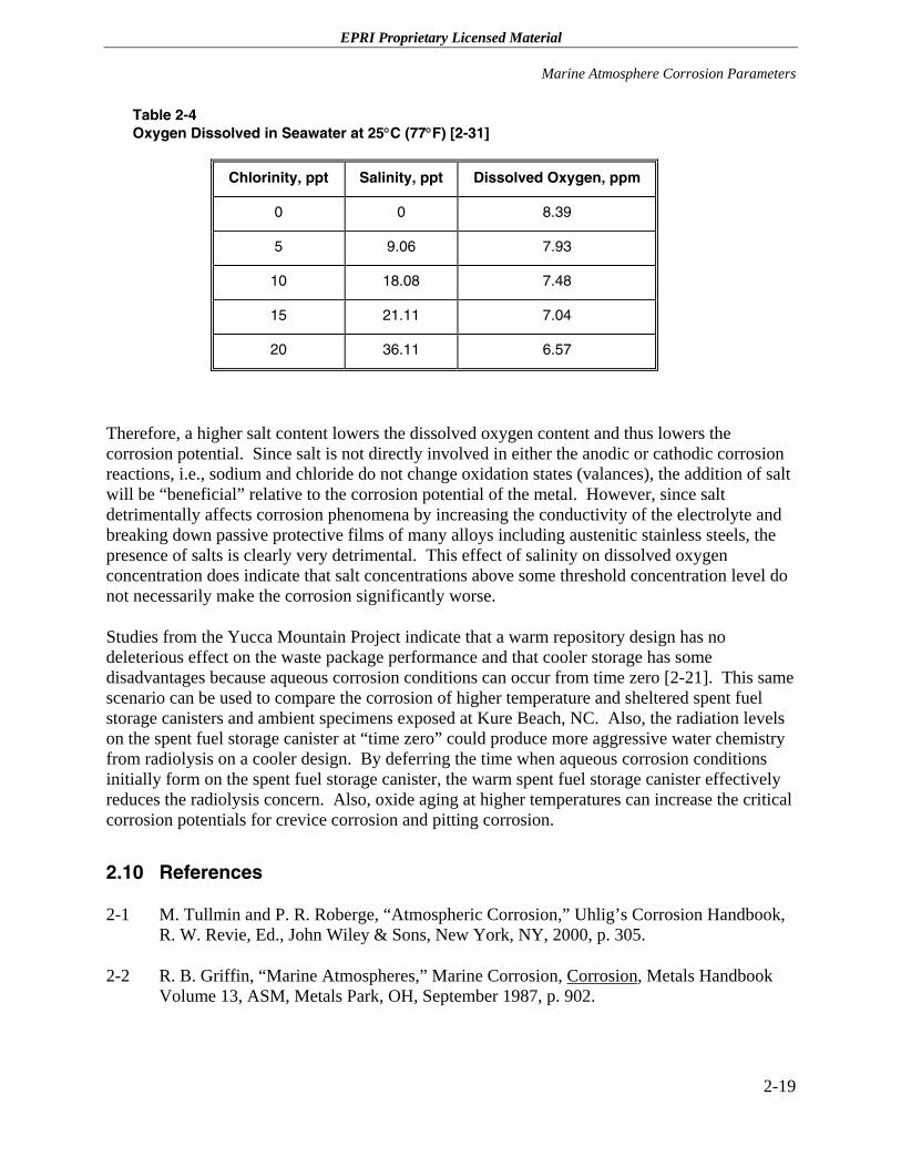
The solubility of oxygen is also affected by the salinity of the environment where the higher the salinity (salt concentration), the lower the dissolved oxygen content. Table 2-4 presents this data for 25°C (77°F) [2-31]. This same effect is observed at lower and higher temperatures as shown previously in Figure 2-7.
2-18
EPRI Proprietary Licensed Material
Marine Atmosphere Corrosion Parameters
Table 2-4 Oxygen Dissolved in Seawater at 25°C (77°F) [2-31]
Chlorinity, ppt Salinity, ppt Dissolved Oxygen, ppm
0 0 8.39
5 9.06 7.93
10 18.08 7.48
15 21.11 7.04
20 36.11 6.57
Therefore, a higher salt content lowers the dissolved oxygen content and thus lowers the corrosion potential. Since salt is not directly involved in either the anodic or cathodic corrosion reactions, i.e., sodium and chloride do not change oxidation states (valances), the addition of salt will be “beneficial” relative to the corrosion potential of the metal. However, since salt detrimentally affects corrosion phenomena by increasing the conductivity of the electrolyte and breaking down passive protective films of many alloys including austenitic stainless steels, the presence of salts is clearly very detrimental. This effect of salinity on dissolved oxygen concentration does indicate that salt concentrations above some threshold concentration level do not necessarily make the corrosion significantly worse.
Studies from the Yucca Mountain Project indicate that a warm repository design has no deleterious effect on the waste package performance and that cooler storage has some disadvantages because aqueous corrosion conditions can occur from time zero [2-21]. This same scenario can be used to compare the corrosion of higher temperature and sheltered spent fuel storage canisters and ambient specimens exposed at Kure Beach, NC. Also, the radiation levels on the spent fuel storage canister at “time zero” could produce more aggressive water chemistry from radiolysis on a cooler design. By deferring the time when aqueous corrosion conditions initially form on the spent fuel storage canister, the warm spent fuel storage canister effectively reduces the radiolysis concern. Also, oxide aging at higher temperatures can increase the critical corrosion potentials for crevice corrosion and pitting corrosion.
2.10 References
2-1 M. Tullmin and P. R. Roberge, “Atmospheric Corrosion,” Uhlig’s Corrosion Handbook, R. W. Revie, Ed., John Wiley & Sons, New York, NY, 2000, p. 305.
2-2 R. B. Griffin, “Marine Atmospheres,” Marine Corrosion, Corrosion, Metals Handbook Volume 13, ASM, Metals Park, OH, September 1987, p. 902.
2-19
EPRI Proprietary Licensed Material Marine Atmosphere Corrosion Parameters
2-3 P. W. Brown and L. W. Masters, “Factors Affecting the Corrosion of Metals in the Atmosphere,” Atmospheric Corrosion, A. H. Ailor, Ed., John Wiley & Sons, New York, NY, 1982, p. 31.
2-4 F. H. Haynie, “Evaluation of Effects of Microclimate Differences on Corrosion,” Atmospheric Corrosion of Metals, S. W. Dean and E. C. Rhea, Eds., ASTM, STP 767, Philadelphia, PA, 1982, p. 286.
2-5 F. H. Haynie, “Economic Assessment of Pollution Related Corrosion Damage,” Atmospheric Corrosion, A. H. Ailor, Ed., John Wiley & Sons, 1982, p. 3.
2-6 M. Schumacher, Ed., Seawater Corrosion Handbook, Noyes Data Corporation, 1979.
2-7 Standard Practice for Evaluating Stress-Corrosion-Cracking Resistance of Metals and Alloys in a Boiling Magnesium Chloride Solution, ASTM Designation: G36-94
2-8 L. Atteraas and S. Haagenrud, “Atmospheric Corrosion in Norway,” Atmospheric Corrosion, A. H. Ailor, Ed., John Wiley & Sons, 1982, p. 873.
2-9 A. C. Dutra and R. de O. Vianna, “Atmospheric Corrosion Testing in Brazil,” Atmospheric Corrosion, A. H. Ailor, Ed., John Wiley & Sons, New York, NY, 1982, p. 755.
2-10 INCO, “Marine Atmospheric Corrosion,” A-1275, New York, NY, March 1978.
2-11 E. A. Baker and T. S. Lee, “Calibration of Atmospheric Corrosion Test Sites,” Atmospheric Corrosion of Metals, S. W. Dean and E. C. Rhea, Eds., ASTM, STP 767, Philadelphia, PA, 1982, p. 250.
2-12 G. A. King and D. J. O’Brien, “The Influence of Marine Environments on Metals and Fabricated Coated Metal Products, Freely Exposed and Partially Sheltered,” Atmospheric Corrosion, W. W. Kirk and H. H. Lawson, Eds., ASTM, STP 1239, Philadelphia, PA, 1995, p. 167.
2-13 C. P. Larrabee, “Corrosion Resistance of High Strength Low Alloy Steels as Influenced by Composition and Environment, Corrosion, Vol. 9, No. 3, March 1953, p. 253.
2-14 L. L. Shreir, “Corrosion in Aqueous Solutions,” Corrosion, Volume 1. Metal/Environmental Reactions, Third Edition, L. L. Shreir, R. A. Jarman, and G. T. Burnstein, Eds., Butterworth-Heinemann Ltd., London, 1994, p. 1:55.
2-15 F. Speller, Corrosion, Causes and Prevention, McGraw-Hill, New York, NY, 1951.
2-16 H. H. Uhlig, “Iron and Steel,” Corrosion Handbook, The Electrochemistry Society, New York, NY, 1948, p. 125.
2-20
EPRI Proprietary Licensed Material
Marine Atmosphere Corrosion Parameters
2-17 H. H. Uhlig, Corrosion and Corrosion Control, John Wiley and Sons, New York, NY, 1963.
2-18 D. M. Brasher and A. D. Mercer, “Comparative Study of Factors Influencing the Action of Corrosion Inhibitors for Mild Steel in Neutral Solutions I. Sodium Benzoate,” British Corrosion Journal, Vol. 3, May 1968, P. 120.
2-19 A. D. Mercer and I. R. Jenkins, “Comparative Study of Factors Influencing the Action of Corrosion Inhibitors for Mild Steel in Neutral Solutions II. Potassium Chromate,” British Corrosion Journal, Vol. 3, May 1968, P. 130.
2-20 A. D. Mercer, I. R. Jenkins and J. E. Rhoades-Brown, “Comparative Study of Factors Influencing the Action of Corrosion Inhibitors for Mild Steel in Neutral Solutions III. Sodium Nitrite,” British Corrosion Journal, Vol. 3, May 1968, P. 130.
2-21 G. S. Frankel, “Pitting Corrosion of Metals; A Review of the Critical Factors,” Journal of the Electrochemical Society, Vol. 145, 1998, p. 2186.
2-22 Z. Szklarska-Smialowska, Corrosion, Vol. 27, 1971, p. 223.
2-23 P. E Arnvig and A. D. Bisgard, “Determining the Potential Independent Critical Pitting Temperature (CPT) by a Potentiostatic Method Using the Avesta Cell,” paper #437 presented at Corrosion 96, NACE, 1996.
2-24 A. J. Sedriks, “Corrosion of Stainless Steels,” J. Wiley and Sons, New York, NY, 1979.
2-25 J. W. Oldfield and W. H. Sutton, “Crevice Corrosion of Stainless Steels,” British Corrosion Journal, Vol. 13, No. 1, 1978
2-26 D. R. McIntyre, “Experience Survey Stress Corrosion Cracking of Austenitic Stainless Steel in Water,” MTI Publication No. 27, February 1987.
2-27 P. L. Andresen, “Perspective on Waste package (WP) Corrosion, Repository Temperature and Transport in the WP,” July 25, 2000.
2-28 L. Greespan, “Humidity Fixed-Points of Binary Saturated Aqueous Solutions,” Journal of Research National Bureau of Standards, Vol. 81 (1A), p. 89.
2-29 E. W. Washburn, editor, “International Critical Tables of Numerical Data, Physics, Chemistry and Technology,” McGraw Hill, New York, NY, 1928.
2-30 C. R. Southwell and J. D. Bultman, “Atmospheric Corrosion Testing in the Tropics,” Atmospheric Corrosion, A. H. Ailor, Ed., John Wiley & Sons, New York, NY, 1982, p. 943.
2-21
EPRI Proprietary Licensed Material Marine Atmosphere Corrosion Parameters
2-31 C. J. J. Fox, Conseil Permanent International pour l’Exploration de la Mer, Copenhagen, Publication de Circonstance, Vol. 41, 1907.
2-22
EPRI Proprietary Licensed Material
3-1
3 MARINE ATMOSPHERE CORROSION OF STAINLESS STEELS
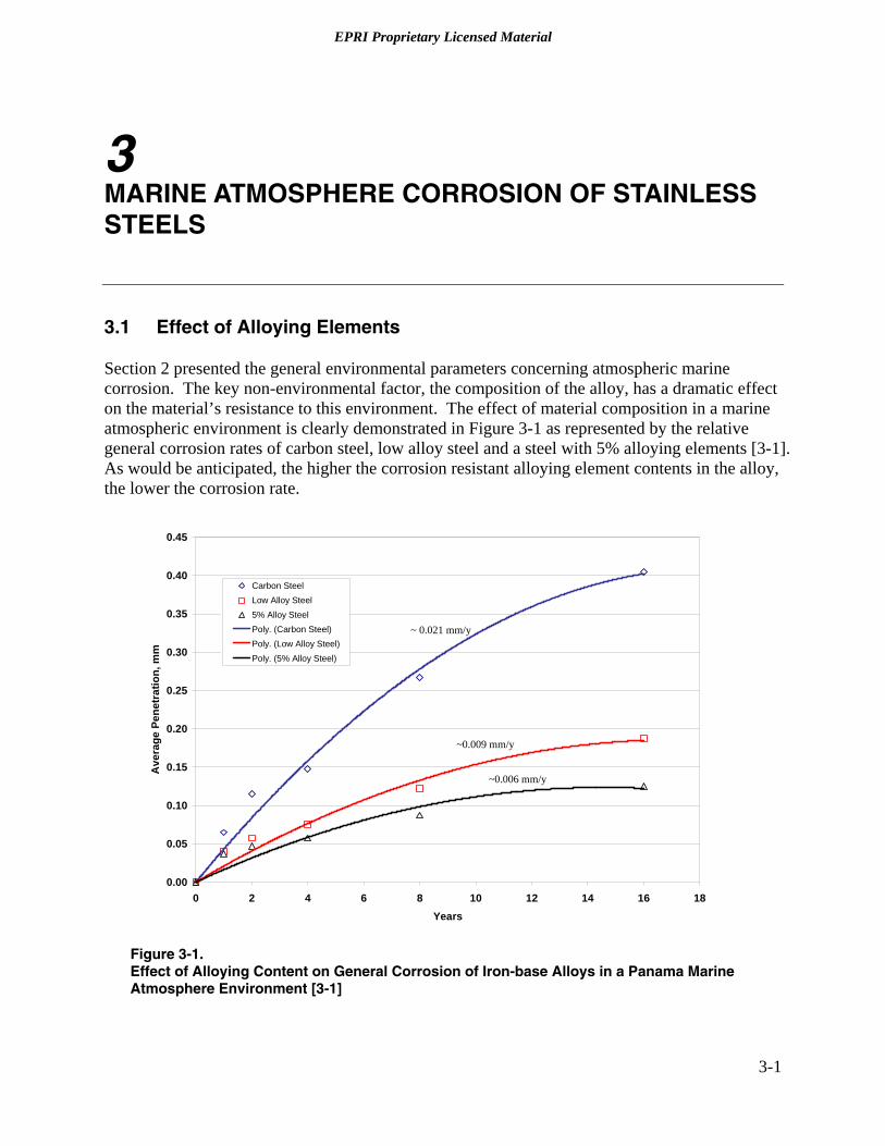
3.1 Effect of Alloying Elements
Section 2 presented the general environmental parameters concerning atmospheric marine corrosion. The key non-environmental factor, the composition of the alloy, has a dramatic effect on the material’s resistance to this environment. The effect of material composition in a marine atmospheric environment is clearly demonstrated in Figure 3-1 as represented by the relative general corrosion rates of carbon steel, low alloy steel and a steel with 5% alloying elements [3-1]. As would be anticipated, the higher the corrosion resistant alloying element contents in the alloy, the lower the corrosion rate.
0.00
0.05
0.10
0.15
0.20
0.25
0.30
0.35
0.40
0.45
0 2 4 6 8 10 12 14 16 18Years
Ave
rage
Pen
etra
tion,
mm
Carbon SteelLow Alloy Steel5% Alloy SteelPoly. (Carbon Steel)Poly. (Low Alloy Steel)Poly. (5% Alloy Steel)
~ 0.021 mm/y
~0.006 mm/y
~0.009 mm/y
Figure 3-1. Effect of Alloying Content on General Corrosion of Iron-base Alloys in a Panama Marine Atmosphere Environment [3-1]
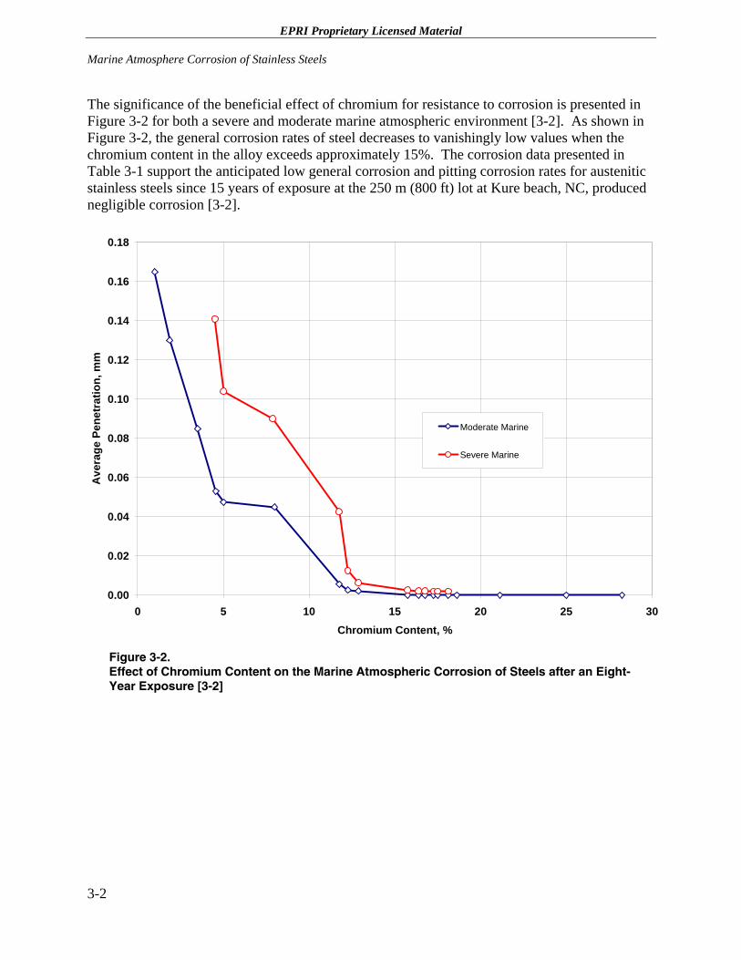
EPRI Proprietary Licensed Material Marine Atmosphere Corrosion of Stainless Steels
3-2
The significance of the beneficial effect of chromium for resistance to corrosion is presented in Figure 3-2 for both a severe and moderate marine atmospheric environment [3-2]. As shown in Figure 3-2, the general corrosion rates of steel decreases to vanishingly low values when the chromium content in the alloy exceeds approximately 15%. The corrosion data presented in Table 3-1 support the anticipated low general corrosion and pitting corrosion rates for austenitic stainless steels since 15 years of exposure at the 250 m (800 ft) lot at Kure beach, NC, produced negligible corrosion [3-2].
0.00
0.02
0.04
0.06
0.08
0.10
0.12
0.14
0.16
0.18
0 5 10 15 20 25 30Chromium Content, %
Ave
rage
Pen
etra
tion,
mm
Moderate Marine
Severe Marine
Figure 3-2. Effect of Chromium Content on the Marine Atmospheric Corrosion of Steels after an Eight-Year Exposure [3-2]
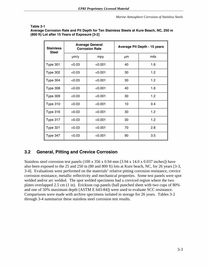
EPRI Proprietary Licensed Material
Marine Atmosphere Corrosion of Stainless Steels
3-3
Table 3-1 Average Corrosion Rate and Pit Depth for Ten Stainless Steels at Kure Beach, NC, 250 m (800 ft) Lot after 15 Years of Exposure [3-2]
Average General Corrosion Rate
Average Pit Depth - 15 years Stainless Steel
µm/y mpy µm mils
Type 301 <0.03 <0.001 40 1.6
Type 302 <0.03 <0.001 30 1.2
Type 304 <0.03 <0.001 30 1.2
Type 308 <0.03 <0.001 40 1.6
Type 309 <0.03 <0.001 30 1.2
Type 310 <0.03 <0.001 10 0.4
Type 316 <0.03 <0.001 30 1.2
Type 317 <0.03 <0.001 30 1.2
Type 321 <0.03 <0.001 70 2.8
Type 347 <0.03 <0.001 90 3.5
3.2 General, Pitting and Crevice Corrosion
Stainless steel corrosion test panels (100 x 356 x 0.94 mm [3.94 x 14.0 x 0.037 inches]) have also been exposed to the 25 and 250 m (80 and 800 ft) lots at Kure beach, NC, for 26 years [3-3, 3-4]. Evaluations were performed on the materials’ relative pitting corrosion resistance, crevice corrosion resistance, metallic reflectivity and mechanical properties. Some test panels were spot welded and/or arc welded. The spot welded specimens had a creviced region where the two plates overlapped 2.5 cm (1 in). Erickson cup panels (ball punched sheet with two cups of 80% and one of 50% maximum depth [ASTM E 643-84]) were used to evaluate SCC resistance. Comparisons were made with archive specimens isolated in storage for 26 years. Tables 3-2 through 3-4 summarize these stainless steel corrosion test results.
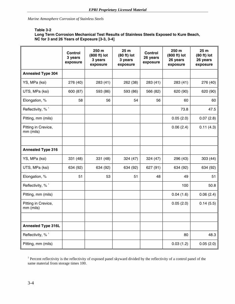
EPRI Proprietary Licensed Material Marine Atmosphere Corrosion of Stainless Steels
3-4
Table 3-2 Long Term Corrosion Mechanical Test Results of Stainless Steels Exposed to Kure Beach, NC for 3 and 26 Years of Exposure [3-3, 3-4]
Control 3 years
exposure
250 m (800 ft) lot
3 years exposure
25 m (80 ft) lot 3 years
exposure
Control 26 years exposure
250 m (800 ft) lot 26 years exposure
25 m (80 ft) lot 26 years exposure
Annealed Type 304
YS, MPa (ksi) 276 (40) 283 (41) 262 (38) 283 (41) 283 (41) 276 (40)
UTS, MPa (ksi) 600 (87) 593 (86) 593 (86) 566 (82) 620 (90) 620 (90)
Elongation, % 58 56 54 56 60 60
Reflectivity, % 1 73.8 47.5
Pitting, mm (mils) 0.05 (2.0) 0.07 (2.8)
Pitting in Crevice, mm (mils)
0.06 (2.4) 0.11 (4.3)
Annealed Type 316
YS, MPa (ksi) 331 (48) 331 (48) 324 (47) 324 (47) 296 (43) 303 (44)
UTS, MPa (ksi) 634 (92) 634 (92) 634 (92) 627 (91) 634 (92) 634 (92)
Elongation, % 51 53 51 48 49 51
Reflectivity, % 1 100 50.8
Pitting, mm (mils) 0.04 (1.6) 0.06 (2.4)
Pitting in Crevice, mm (mils)
0.05 (2.0) 0.14 (5.5)
Annealed Type 316L
Reflectivity, % 1 80 48.3
Pitting, mm (mils) 0.03 (1.2) 0.05 (2.0)
1 Percent reflectivity is the reflectivity of exposed panel skyward divided by the reflectivity of a control panel of the same material from storage times 100.
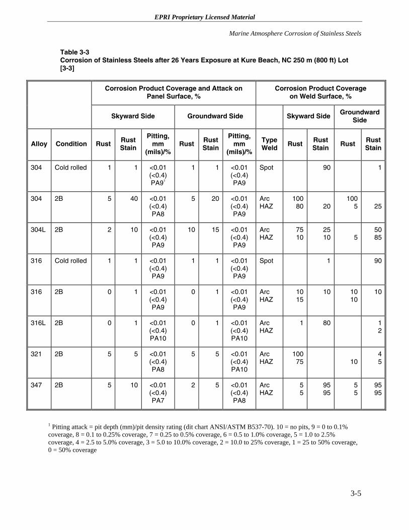
EPRI Proprietary Licensed Material
Marine Atmosphere Corrosion of Stainless Steels
3-5
Table 3-3 Corrosion of Stainless Steels after 26 Years Exposure at Kure Beach, NC 250 m (800 ft) Lot [3-3]
Corrosion Product Coverage and Attack on Panel Surface, %
Corrosion Product Coverage on Weld Surface, %
Skyward Side Groundward Side Skyward Side Groundward Side
Alloy Condition Rust Rust Stain
Pitting, mm
(mils)/%Rust Rust
Stain
Pitting, mm
(mils)/%
Type Weld
Rust Rust Stain
Rust Rust Stain
304 Cold rolled 1 1 <0.01 (<0.4) PA91
1 1 <0.01 (<0.4) PA9
Spot 90 1
304 2B 5 40 <0.01 (<0.4) PA8
5 20 <0.01 (<0.4) PA9
Arc HAZ
100 80 20
1005 25
304L 2B 2 10 <0.01 (<0.4) PA9
10 15 <0.01 (<0.4) PA9
Arc HAZ
75 10
2510 5
5085
316 Cold rolled 1 1 <0.01 (<0.4) PA9
1 1 <0.01 (<0.4) PA9
Spot 1 90
316 2B 0 1 <0.01 (<0.4) PA9
0 1 <0.01 (<0.4) PA9
Arc HAZ
10 15
10 1010
10
316L 2B 0 1 <0.01 (<0.4) PA10
0 1 <0.01 (<0.4) PA10
Arc HAZ
1
80 12
321 2B 5 5 <0.01 (<0.4) PA8
5 5 <0.01 (<0.4) PA10
Arc HAZ
100 75 10
45
347 2B 5 10 <0.01 (<0.4) PA7
2 5 <0.01 (<0.4) PA8
Arc HAZ
5 5
9595
55
9595
1 Pitting attack = pit depth (mm)/pit density rating (dit chart ANSI/ASTM B537-70). 10 = no pits, 9 = 0 to 0.1% coverage, 8 = 0.1 to 0.25% coverage, 7 = 0.25 to 0.5% coverage, 6 = 0.5 to 1.0% coverage, 5 = 1.0 to 2.5% coverage, 4 = 2.5 to 5.0% coverage, 3 = 5.0 to 10.0% coverage, 2 = 10.0 to 25% coverage, 1 = 25 to 50% coverage, 0 = 50% coverage
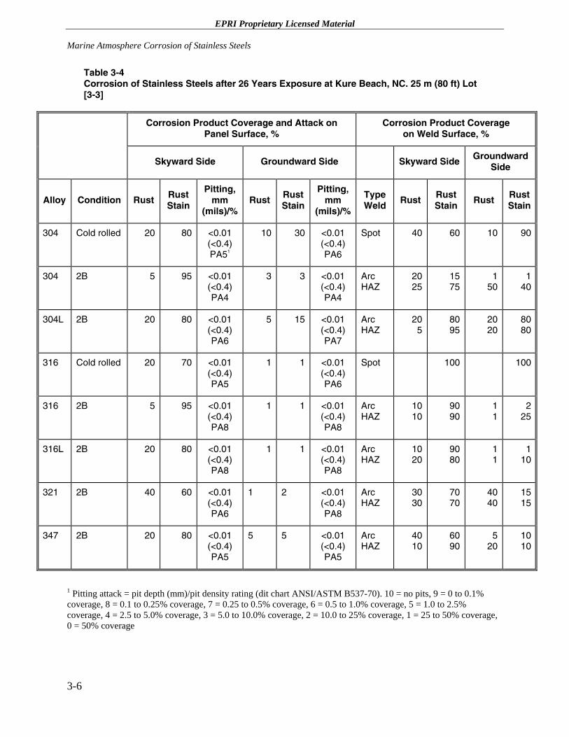
EPRI Proprietary Licensed Material Marine Atmosphere Corrosion of Stainless Steels
3-6
Table 3-4 Corrosion of Stainless Steels after 26 Years Exposure at Kure Beach, NC. 25 m (80 ft) Lot [3-3]
Corrosion Product Coverage and Attack on Panel Surface, %
Corrosion Product Coverage on Weld Surface, %
Skyward Side Groundward Side Skyward Side Groundward Side
Alloy Condition Rust Rust Stain
Pitting, mm
(mils)/%Rust Rust
Stain
Pitting, mm
(mils)/%
Type Weld
Rust Rust Stain
Rust Rust Stain
304 Cold rolled 20 80 <0.01 (<0.4) PA51
10 30 <0.01 (<0.4) PA6
Spot 40 60 10 90
304 2B 5 95 <0.01 (<0.4) PA4
3 3 <0.01 (<0.4) PA4
Arc HAZ
20 25
1575
150
140
304L 2B 20 80 <0.01 (<0.4) PA6
5 15 <0.01 (<0.4) PA7
Arc HAZ
20 5
8095
2020
8080
316 Cold rolled 20 70 <0.01 (<0.4) PA5
1 1 <0.01 (<0.4) PA6
Spot 100 100
316 2B 5 95 <0.01 (<0.4) PA8
1 1 <0.01 (<0.4) PA8
Arc HAZ
10 10
9090
11
225
316L 2B 20 80 <0.01 (<0.4) PA8
1 1 <0.01 (<0.4) PA8
Arc HAZ
10 20
9080
11
110
321 2B 40 60 <0.01 (<0.4) PA6
1 2 <0.01 (<0.4) PA8
Arc HAZ
30 30
7070
4040
1515
347 2B 20 80 <0.01 (<0.4) PA5
5 5 <0.01 (<0.4) PA5
Arc HAZ
40 10
6090
520
1010
1 Pitting attack = pit depth (mm)/pit density rating (dit chart ANSI/ASTM B537-70). 10 = no pits, 9 = 0 to 0.1% coverage, 8 = 0.1 to 0.25% coverage, 7 = 0.25 to 0.5% coverage, 6 = 0.5 to 1.0% coverage, 5 = 1.0 to 2.5% coverage, 4 = 2.5 to 5.0% coverage, 3 = 5.0 to 10.0% coverage, 2 = 10.0 to 25% coverage, 1 = 25 to 50% coverage, 0 = 50% coverage
EPRI Proprietary Licensed Material
Marine Atmosphere Corrosion of Stainless Steels
3-7
3.2.1 Types 304 and 304L Stainless Steel – 26 Years of Exposure
3.2.1.1 25 m (80 ft) Lot
Cold-rolled Type 304 stainless steel exposed at the 25 m (80 ft) lot was 20% covered by rust with the balance of the surface area covered by a rust stain [3-3]. The pits were <0.01 mm (<0.4 mils) deep and the pit density was 2.5% of the area. Soft 2B (Note: a 2B finish is cold rolled annealed and pickled followed by a final light cold roll pass generally on highly polished rolls) Type 304 stainless steel was 5% covered by rust with the balance of the surface area covered by a rust stain. The pits were <0.01 mm (<0.4 mils) deep and the pit density was 5% of the area. Soft 2B (bright cold rolled) Type 304L stainless steel was 20% covered by rust with the balance of the surface area covered by a rust stain. The pits were <0.01 mm (<0.4 mils) deep and the pit density was 1% of the area.
Spot-welded Type 304 stainless steel (soft cold rolled) had a slight rust build-up in between the two welded plates. Numerous pits, 0.1 mm (4 mils) maximum depth and 0.08 mm (0.3 mils) average depth, were identified in the crevice area. Intergranular attack (IGA) was also found in the weld and weld heat affected zone (HAZ). There were no indications of MIC.
3.2.1.2 250 m (800 ft) Lot
Cold-rolled Type 304 stainless steel exposed at the 250 m (800 ft) lot was 1% covered with rust spotting and 2% rust staining [3-3]. The pits were <0.01 mm (<0.4 mils) deep and the pit density was 0.25% of the area. Soft 2B Type 304 stainless steel was 5% covered by rust spots with 40% of the surface area covered by a rust stain. The pits were <0.01 mm (<0.4 mils) deep and the pit density was 0.25% of the area. Soft 2B Type 304L stainless steel was 2% covered by rust spots and 10% covered by a rust stain. The pits were 0.01 mm (0.4 mils) deep and the pit density was 0.1% of the area.
Spot-welded Type 304 stainless steel (soft cold rolled) had a slight rust and rust stain in between the two welded plates. Pits, 0.06 mm (2.4 mils) maximum depth and 0.04 mm (0.15 mils) average depth, were scattered in the crevice area. Pitting was also found in the weld HAZ. There were no indications of MIC.
3.2.2 Type 316 and 316L Stainless Steel – 26 Years of Exposure
3.2.2.1 25 m (80 ft) Lot
Cold-rolled Type 316 stainless steel exposed at the 25 m (80 ft) lot was 20% covered by rust and 70% covered by a rust stain [3-3]. The pits were <0.01 mm (<0.4 mils) deep and the pit density was 2.5% of the area. Soft 2B Type 316 stainless steel was 5% covered by rust and 50% covered by a rust stain. The pits were 0.01 mm (0.4 mils) deep and the pit density was 0.25% of the area. Soft 2B Type 316L stainless steel was 20% covered by rust with the balance of the surface area
EPRI Proprietary Licensed Material Marine Atmosphere Corrosion of Stainless Steels
3-8
covered by a rust stain. The pits were <0.01 mm (<0.4 mils) deep and the pit density was 0.25% of the area.
Spot-welded Type 316 stainless steel (soft cold rolled) had a slight rust build-up in between the two welded plates. Numerous pits, 0.14 mm (5.5 mils) maximum depth and 0.09 mm (0.35 mils) average depth, were scattered in the crevice area. IGA was also found in the weld and weld HAZ. There were no indications of MIC.
3.2.2.2 250 m (800 ft) Lot
Cold-rolled Type 316 stainless steel exposed at the 250 m (800 ft) lot was 1% covered with rust spots and 1% rust staining [3-3]. The pits were <0.01 mm (<0.4 mils) and the pit density was 0.1% of the area. Soft 2B Type 316 stainless steel had no rust spotting with only 1% of the surface area covered by a rust stain. The pits were <0.01 mm (<0.4 mils) and the pit density was 0.25% of the area. Soft 2B Type 316L stainless steel had no rust spots with only 1% covered by a rust stain. No pits were visible on the Type 316L stainless steel surface.
Spot-welded Type 316 stainless steel (soft cold rolled) had a slight rust and rust stain in between the two welded plates. Several small pits, 0.01 mm (0.4 mils) maximum depth and a small crevice corrosion site, 0.01 mm (0.4 mils) deep, were found. IGA was also found in the weld HAZ. There were no indications of MIC.
3.2.3 Kure Beach Corrosion Summary
All the stainless steels exposed in this test program exhibited rust staining and rust coverage to varying degrees. As would be anticipated, the effect was more prominent at the 25 m (80 ft) lot, i.e., nearest the ocean, as compared to the 250 m (800 ft) lot. Types 304 and 316 stainless steel exhibited the least rust coverage compared to other 200, 300 and 400 series stainless steels tested at the 25 m (80 ft) lot.
Pitting and IGA in the creviced region were identified in the creviced spot-welded stainless steel specimens. None of the arc-welded specimens indicated evidence of weld failure and no Erickson cup panels revealed evidence of SCC.
The results indicate that the Type 304 and 316 stainless steels exposed to a severe marine atmosphere environment also had no loss in mechanical properties after 26 years of exposure [3-4]. In general, the stainless steels exposed in this marine study exhibited the following characteristics:
1. Rust and rust staining that was dependent on alloy content and distance from the ocean.
2. Shallow pitting and crevice corrosion.
3. Sound arc welds with no cracking.
4. No loss in mechanical properties.
5. No indications of MIC.
EPRI Proprietary Licensed Material
Marine Atmosphere Corrosion of Stainless Steels
3-9
3.3 Marine Environment Stress Corrosion Cracking Investigations
3.3.1 Kure Beach SCC Studies
A simple SCC test study that was initiated in the mid-1950s utilized 6.6 x 1.1 cm (2.5 x 0.44 inch) Type 303 and 316 stainless steel studs threaded into a bronze bar [3-5]. A bronze sleeve was placed over the stud followed by a stainless steel washer and nut. The nuts were subsequently torqued to a predetermined load and the assembly was exposed in the 250 m (800 ft) lot at Kure Beach, NC. Upon re-torquing four months later, cracking was observed in all five Type 303 stainless steel studs torqued to 108 to 122 N-m (80 to 90 ft lbs), but no cracking was observed in four Type 303 stainless steel studs torqued to 90 to 105 N-m (70 to 77.5 ft lbs). Type 316 stainless steel studs torqued to 98 to 102 N-m (72.5 to 75 ft lbs) suffered SCC, while no cracking was observed in seven Type 316 stainless steel studs torqued to 75 to 90 N-m (55 to 70 ft lbs). Albeit there was no discussion of the SCC mode or crack location in the brief internal memo that summarized these results, it was conjectured that crevice corrosion associated with the nuts and washers was likely to have occurred and contributed to the failures at the higher load (stress) conditions.
Another SCC study was conducted for five years at the 25 m (80 ft) lot at Kure Beach, NC from 1973 to 1978 using U-bend, three-point bent beam and cantilever beam SCC specimens [3-5, 3-6]. Although both annealed and cold worked U-bends of numerous heats of several types of austenitic stainless steels (e.g., Types 301, 302, 304, 304L, 309, 310 and 316 stainless steel) did not suffer SCC in five years of sheltered or bold exposure, furnace sensitized U-bends fabricated did suffer SCC. In three-point bent beam SCC tests on cold worked (1/4 hard) or furnace sensitized Type 301 and 304 stainless steel exposed at three locations, i.e., the 25 m (80 ft) lot (sheltered and bold exposure), the 250 m (800 ft) lot (open exposure) and located under the wharf at applied tensile stresses either 50 or 80% of the yield strength, only the furnace sensitized specimens suffered SCC. Finally, Type 301 stainless steel cantilever beam specimens with circular or cross weldments were tested at the 25 m (80 ft) lot where no SCC was identified on any of these welded specimens.
3.3.2 Long-Term Japanese SCC Studies
A more extensive and more realistic 15-year marine atmosphere exposure test has been performed in Japan [3-7]. Specimens of Types 304, 304L, 316 and 316L stainless steels were exposed to a sub tropical zone 20 m (66 ft) from the seashore in Okinawa, Japan and to a temperate zone 13 m (43 ft) from the seashore in Okitsu (Chiba), Japan. These tests were specifically designed to determine the effects of marine atmospheres on SCC of stainless steel under simulated real-world component conditions. That is, two types of welded specimens (X and Y) were fabricated to resemble actual structures rather than simple flat corrosion coupons, Figure 3-3.
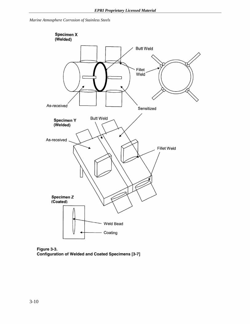
EPRI Proprietary Licensed Material Marine Atmosphere Corrosion of Stainless Steels
3-10
Figure 3-3. Configuration of Welded and Coated Specimens [3-7]
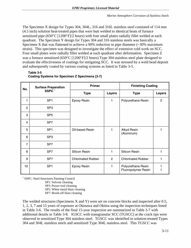
EPRI Proprietary Licensed Material
Marine Atmosphere Corrosion of Stainless Steels
3-11
The Specimen X design for Types 304, 304L, 316 and 316L stainless steel consisted of 114 mm (4.5 inch) solution heat-treated pipes that were butt welded to identical heats of furnace sensitized pipe (650°C [1200°F]/2 hours) with four small plates radially fillet welded at each quadrant. The Specimen Y design for Types 304 and 316 stainless steels was basically a Specimen X that was flattened to achieve a 90% reduction in pipe diameter (~30% maximum strain). This specimen was designed to investigate the effect of extensive cold work on SCC. Four small plates were radially fillet welded at each quadrant after deformation. Specimen Z was a furnace sensitized (650°C [1200°F]/2 hours) Type 304 stainless steel plate designed to evaluate the effectiveness of coatings for mitigating SCC. It was stressed by a weld bead deposit and subsequently coated by various coating systems as listed in Table 3-5.
Table 3-5 Coating Systems for Specimen Z Specimens [3-7]
Primer Finishing Coating No. Surface Preparation
SSPC 1
Type Layers Type Layers
1 SP1
2 SP3
3 SP5
4 SP7
Epoxy Resin 1 Polyurethane Resin 2
5 SP1
6 SP3
7 SP7
Oil-based Resin 1 Alkyd Resin (Aluminum)
1
8 SP7 Silicon Resin 1 Silicon Resin 1
9 SP7 Chlorinated Rubber 2 Chlorinated Rubber 1
10 SP1 Epoxy Resin 1 Polyurethane Resin Fluoropolymer Resin
1 1
1 SSPC: Steel Structures Painting Council SP1: Solvent cleaning SP3: Power tool cleaning SP5: White metal blast cleaning SP7: Brush-off blast cleaning
The welded structures (Specimens X and Y) were set on concrete blocks and inspected after 0.5, 1, 2, 3, 7 and 15 years of exposure at Okinawa and Okitsu using the inspection techniques listed in Table 3-6. The results of the final 15-year inspection are summarized in Table 3-7 with additional details in Table 3-8. IGSCC with transgranular SCC (TGSCC) at the crack tips were observed in sensitized Type 304 stainless steel. TGSCC was identified in solution-treated Types 304 and 304L stainless steels and sensitized Type 304L stainless steel. This TGSCC was
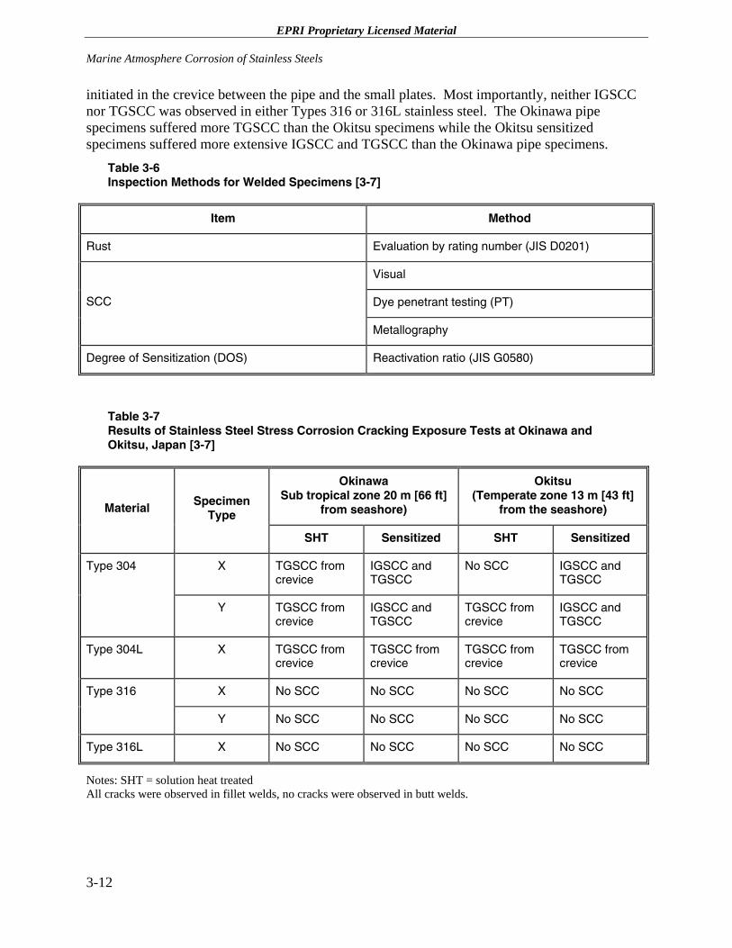
EPRI Proprietary Licensed Material Marine Atmosphere Corrosion of Stainless Steels
3-12
initiated in the crevice between the pipe and the small plates. Most importantly, neither IGSCC nor TGSCC was observed in either Types 316 or 316L stainless steel. The Okinawa pipe specimens suffered more TGSCC than the Okitsu specimens while the Okitsu sensitized specimens suffered more extensive IGSCC and TGSCC than the Okinawa pipe specimens.
Table 3-6 Inspection Methods for Welded Specimens [3-7]
Item Method
Rust Evaluation by rating number (JIS D0201)
Visual
Dye penetrant testing (PT) SCC
Metallography
Degree of Sensitization (DOS) Reactivation ratio (JIS G0580)
Table 3-7 Results of Stainless Steel Stress Corrosion Cracking Exposure Tests at Okinawa and Okitsu, Japan [3-7]
Okinawa Sub tropical zone 20 m [66 ft]
from seashore)
Okitsu (Temperate zone 13 m [43 ft]
from the seashore) Material Specimen Type
SHT Sensitized SHT Sensitized
X TGSCC from crevice
IGSCC and TGSCC
No SCC IGSCC and TGSCC
Type 304
Y TGSCC from crevice
IGSCC and TGSCC
TGSCC from crevice
IGSCC and TGSCC
Type 304L X TGSCC from crevice
TGSCC from crevice
TGSCC from crevice
TGSCC from crevice
X No SCC No SCC No SCC No SCC Type 316
Y No SCC No SCC No SCC No SCC
Type 316L X No SCC No SCC No SCC No SCC
Notes: SHT = solution heat treated All cracks were observed in fillet welds, no cracks were observed in butt welds.
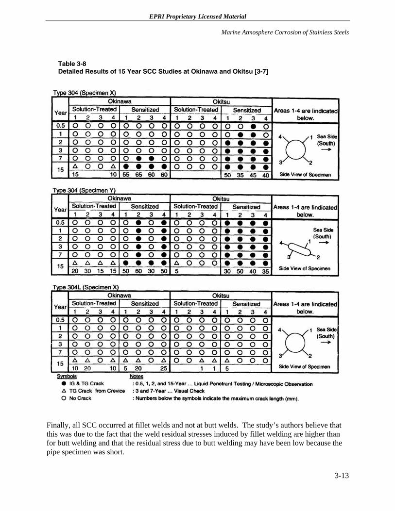
EPRI Proprietary Licensed Material
Marine Atmosphere Corrosion of Stainless Steels
3-13
Table 3-8 Detailed Results of 15 Year SCC Studies at Okinawa and Okitsu [3-7]
Finally, all SCC occurred at fillet welds and not at butt welds. The study’s authors believe that this was due to the fact that the weld residual stresses induced by fillet welding are higher than for butt welding and that the residual stress due to butt welding may have been low because the pipe specimen was short.
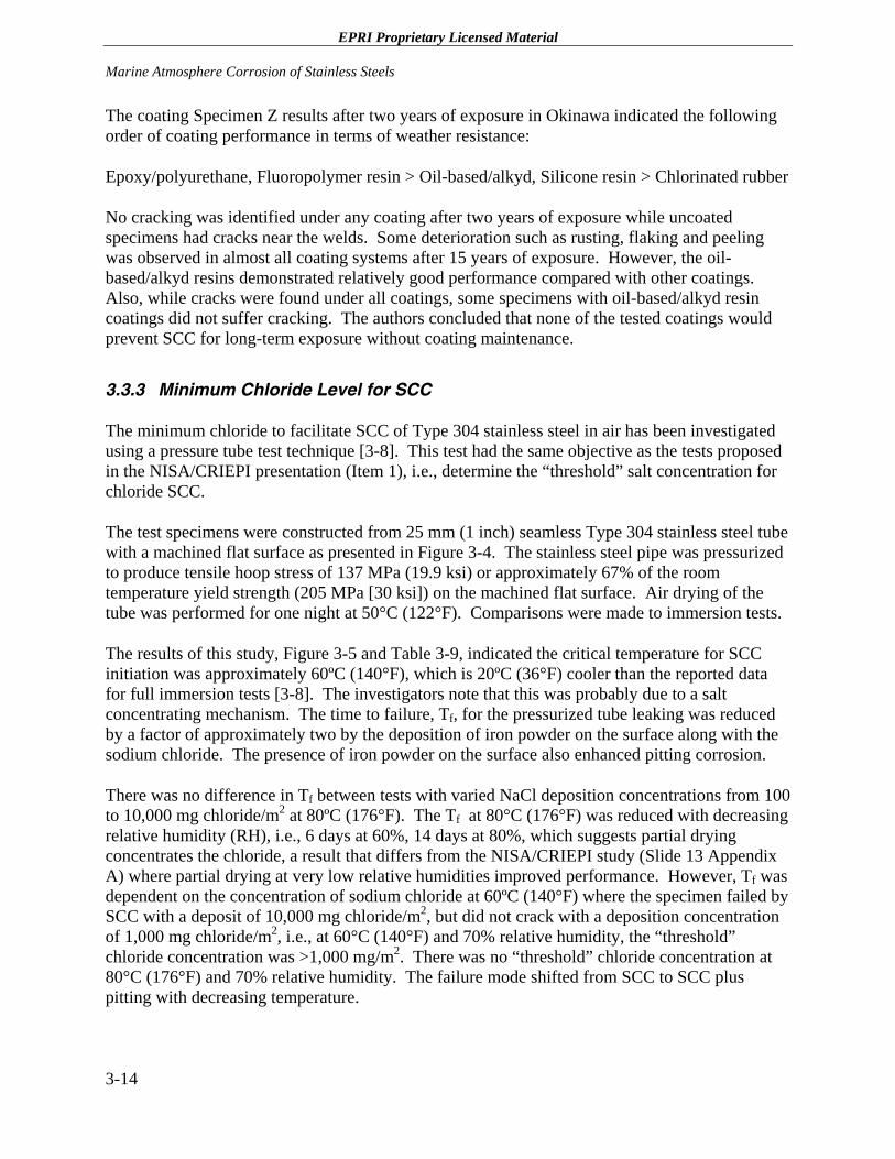
EPRI Proprietary Licensed Material Marine Atmosphere Corrosion of Stainless Steels
3-14
The coating Specimen Z results after two years of exposure in Okinawa indicated the following order of coating performance in terms of weather resistance:
Epoxy/polyurethane, Fluoropolymer resin > Oil-based/alkyd, Silicone resin > Chlorinated rubber
No cracking was identified under any coating after two years of exposure while uncoated specimens had cracks near the welds. Some deterioration such as rusting, flaking and peeling was observed in almost all coating systems after 15 years of exposure. However, the oil-based/alkyd resins demonstrated relatively good performance compared with other coatings. Also, while cracks were found under all coatings, some specimens with oil-based/alkyd resin coatings did not suffer cracking. The authors concluded that none of the tested coatings would prevent SCC for long-term exposure without coating maintenance.
3.3.3 Minimum Chloride Level for SCC
The minimum chloride to facilitate SCC of Type 304 stainless steel in air has been investigated using a pressure tube test technique [3-8]. This test had the same objective as the tests proposed in the NISA/CRIEPI presentation (Item 1), i.e., determine the “threshold” salt concentration for chloride SCC.
The test specimens were constructed from 25 mm (1 inch) seamless Type 304 stainless steel tube with a machined flat surface as presented in Figure 3-4. The stainless steel pipe was pressurized to produce tensile hoop stress of 137 MPa (19.9 ksi) or approximately 67% of the room temperature yield strength (205 MPa [30 ksi]) on the machined flat surface. Air drying of the tube was performed for one night at 50°C (122°F). Comparisons were made to immersion tests.
The results of this study, Figure 3-5 and Table 3-9, indicated the critical temperature for SCC initiation was approximately 60ºC (140°F), which is 20ºC (36°F) cooler than the reported data for full immersion tests [3-8]. The investigators note that this was probably due to a salt concentrating mechanism. The time to failure, Tf, for the pressurized tube leaking was reduced by a factor of approximately two by the deposition of iron powder on the surface along with the sodium chloride. The presence of iron powder on the surface also enhanced pitting corrosion.
There was no difference in Tf between tests with varied NaCl deposition concentrations from 100 to 10,000 mg chloride/m2 at 80ºC (176°F). The Tf at 80°C (176°F) was reduced with decreasing relative humidity (RH), i.e., 6 days at 60%, 14 days at 80%, which suggests partial drying concentrates the chloride, a result that differs from the NISA/CRIEPI study (Slide 13 Appendix A) where partial drying at very low relative humidities improved performance. However, Tf was dependent on the concentration of sodium chloride at 60ºC (140°F) where the specimen failed by SCC with a deposit of 10,000 mg chloride/m2, but did not crack with a deposition concentration of 1,000 mg chloride/m2, i.e., at 60°C (140°F) and 70% relative humidity, the “threshold” chloride concentration was >1,000 mg/m2. There was no “threshold” chloride concentration at 80°C (176°F) and 70% relative humidity. The failure mode shifted from SCC to SCC plus pitting with decreasing temperature.
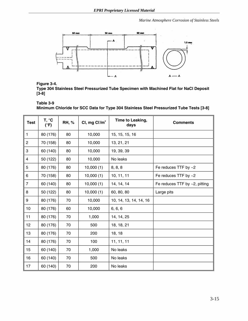
EPRI Proprietary Licensed Material
Marine Atmosphere Corrosion of Stainless Steels
3-15
Figure 3-4. Type 304 Stainless Steel Pressurized Tube Specimen with Machined Flat for NaCl Deposit [3-8]
Table 3-9 Minimum Chloride for SCC Data for Type 304 Stainless Steel Pressurized Tube Tests [3-8]
Test T, °C (°F)
RH, % Cl, mg Cl-/m2 Time to Leaking, days
Comments
1 80 (176) 80 10,000 15, 15, 15, 16
2 70 (158) 80 10,000 13, 21, 21
3 60 (140) 80 10,000 19, 39, 39
4 50 (122) 80 10,000 No leaks
5 80 (176) 80 10,000 (1) 8, 8, 8 Fe reduces TTF by ~2
6 70 (158) 80 10,000 (1) 10, 11, 11 Fe reduces TTF by ~2
7 60 (140) 80 10,000 (1) 14, 14, 14 Fe reduces TTF by ~2, pitting
8 50 (122) 80 10,000 (1) 60, 80, 80 Large pits
9 80 (176) 70 10,000 10, 14, 13, 14, 14, 16
10 80 (176) 60 10,000 6, 6, 6
11 80 (176) 70 1,000 14, 14, 25
12 80 (176) 70 500 18, 18, 21
13 80 (176) 70 200 18, 18
14 80 (176) 70 100 11, 11, 11
15 60 (140) 70 1,000 No leaks
16 60 (140) 70 500 No leaks
17 60 (140) 70 200 No leaks
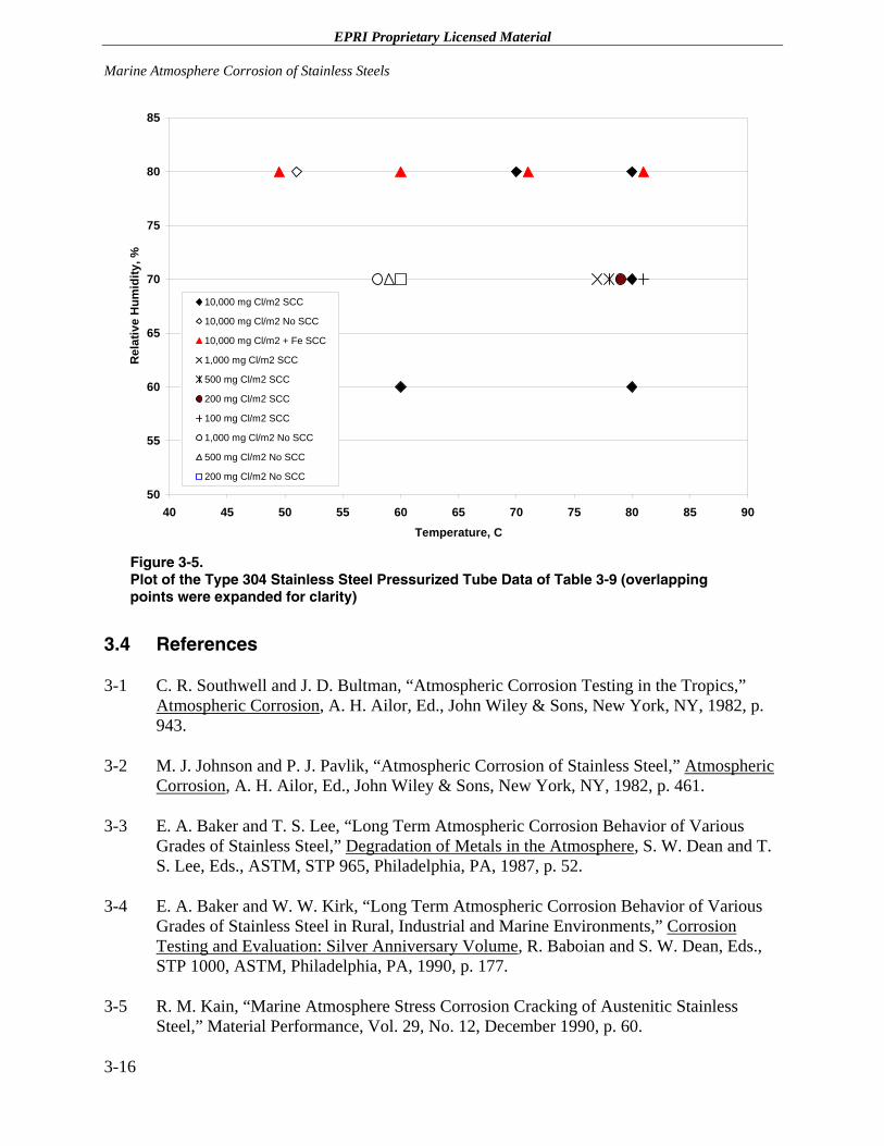
EPRI Proprietary Licensed Material Marine Atmosphere Corrosion of Stainless Steels
3-16
50
55
60
65
70
75
80
85
40 45 50 55 60 65 70 75 80 85 90Temperature, C
Rel
ativ
e H
umid
ity, %
10,000 mg Cl/m2 SCC
10,000 mg Cl/m2 No SCC
10,000 mg Cl/m2 + Fe SCC
1,000 mg Cl/m2 SCC
500 mg Cl/m2 SCC
200 mg Cl/m2 SCC
100 mg Cl/m2 SCC
1,000 mg Cl/m2 No SCC
500 mg Cl/m2 No SCC
200 mg Cl/m2 No SCC
Figure 3-5. Plot of the Type 304 Stainless Steel Pressurized Tube Data of Table 3-9 (overlapping points were expanded for clarity)
3.4 References
3-1 C. R. Southwell and J. D. Bultman, “Atmospheric Corrosion Testing in the Tropics,” Atmospheric Corrosion, A. H. Ailor, Ed., John Wiley & Sons, New York, NY, 1982, p. 943.
3-2 M. J. Johnson and P. J. Pavlik, “Atmospheric Corrosion of Stainless Steel,” Atmospheric Corrosion, A. H. Ailor, Ed., John Wiley & Sons, New York, NY, 1982, p. 461.
3-3 E. A. Baker and T. S. Lee, “Long Term Atmospheric Corrosion Behavior of Various Grades of Stainless Steel,” Degradation of Metals in the Atmosphere, S. W. Dean and T. S. Lee, Eds., ASTM, STP 965, Philadelphia, PA, 1987, p. 52.
3-4 E. A. Baker and W. W. Kirk, “Long Term Atmospheric Corrosion Behavior of Various Grades of Stainless Steel in Rural, Industrial and Marine Environments,” Corrosion Testing and Evaluation: Silver Anniversary Volume, R. Baboian and S. W. Dean, Eds., STP 1000, ASTM, Philadelphia, PA, 1990, p. 177.
3-5 R. M. Kain, “Marine Atmosphere Stress Corrosion Cracking of Austenitic Stainless Steel,” Material Performance, Vol. 29, No. 12, December 1990, p. 60.
EPRI Proprietary Licensed Material
Marine Atmosphere Corrosion of Stainless Steels
3-17
3-6 K. L. Money and W. W. Kirk, “Stress Corrosion Cracking Behavior of Wrought Fe-Cr-Ni Alloys in Marine Atmosphere,” Material Performance, Vol. 17, No. 7, July 1978, p. 28.
3-7 Y. Toshima, et al., “Long-Term Exposure Test for External Stress Corrosion Cracking on Austenitic Stainless Steels in Coastal Areas,” paper 456 presented at Corrosion 2000, NACE, Orlando, FL, March 27, 2000.
3-8 M. Yajima and M. Arii, “Chloride Stress Corrosion Cracking of AISI 304 Stainless Steel in Air,” Materials Performance, Vol. 19, No. 10, December 1980, p. 17.

EPRI Proprietary Licensed Material
4 EXAMPLES OF STAINLESS STEEL SCC IN MARINE ATMOSPHERE ENVIRONMENTS
4.1 Introduction
This section of the report provides examples of actual field investigations on the SCC of stainless steel at ambient temperatures in marine-type or chloride-contaminated environments that occurred prior to and after facility operation. Contributing factors leading to SCC of components prior to operation include furnace sensitized or weld sensitization of stainless steel components during fabrication or assembly, surface contamination through the deliberate, but ill-considered, use of chloride containing miscellaneous materials such as tapes, coatings, gaskets, insulation, etc., and residual contaminants from inadequate rinsing of etchants, etc. [4-1] This list of contributing factors can be augmented by contamination that incurred during storage at the construction site or during the construction process itself.
4.2 Field Experience with Stainless Steel SCC in Marine-type Environments
4.2.1 Examples of Pre-operational Stainless Steel SCC
4.2.1.1 Example 1 - Peach Bottom High Temperature Gas Reactor
Peach Bottom High Temperature Gas Reactor’s steam generators contained Type 304L stainless steel bellows, superheater tubes and superheater steam outlet piping. The units had been stress relieved at 595°C (1100°F), which can furnace sensitized the austenitic stainless steel if the exposure time is sufficiently long [4-1, 4-2]. Both IGSCC and TGSCC were observed in the furnace sensitized stainless steel components. Chlorides were detected in the range 0.15 to 0.46 µg/cm2 (1-3 µg/in2) in surface deposits while the hydrotest water contained <1 ppm chlorides, 4 ppm fluoride and <8 ppm dissolved oxygen. Although the root cause of the SCC was not unequivocally established, it was suggested that chloride was a key environmental parameter responsible for the SCC.
4.2.1.2 Example 2 – Oyster Creek and Tarapur BWRs
The pattern of cracking observed at Peach Bottom was also identified at the Oyster Creek [4-1, 4-3] and Tarapur boiling water reactors (BWRs) [4-1, 4-4]. IGSCC was detected in the Oyster
4-1
EPRI Proprietary Licensed Material Examples of Stainless Steel SCC in Marine Atmosphere Environments
Creek pressure vessel Type 304 stainless steel internals and the Tarapur steam generators. The units were fabricated with the internals installed prior to the stress relief heat treatment. The most severely attacked components in the pressure vessels were the furnace sensitized stub tubes located in the lower head region. These stub tubes serve as transition pieces between the pressure vessel and the tubes containing the control rods. High residual stresses were measured in the stub tubes above the toe of the weld. Although the specific source of the chloride was not established, there was an adequate supply of chlorides from the marine atmosphere, since both the Oyster Creek and Tarapur reactor sites are adjacent to the ocean.
4.2.1.3 Example 3 – Homogeneous Reactor
An early example of failure prior to startup occurred at the Homogeneous Reactor [4-1, 4-5]. TGSCC was detected in Type 347 stainless steel tubing, which is a part of the secondary system used to detect leaks at flanged joints and in the Type 304 stainless steel flanges. The fluid drained from the secondary system contained approximately 1000 ppm chloride. The source of the chlorides was believed to have been a chlorinated hydrocarbon lubricant used during the fabrication of the tubing.
4.2.1.4 Example 4 – Sodium Component Test Facility
The Sodium Component Test Facility located in Simi Valley, CA served as a mockup for sodium systems that were to be used in liquid metal fast breeder reactors (LMFBRs) [4-1, 4-6]. A Type 304 stainless steel bellows was found to be cracked prior to system start up. This bellows had been heat treated at 700°C (1292°F) to volatize and remove residual impurities, and, in the process became thoroughly furnace sensitized. The IGSCC was believed due to 30 months exposure to atmospheric moisture.
4.2.1.5 Example 5 – N. S. Savannah
Chlorides that were leached from insulation during pre-startup tests attacked the external surfaces of the N.S. Savannah Type 304 stainless steel primary system [4-1, 4-7].
4.2.1.6 Example 6 – Savannah River Plant
Several cases of SCC occurred in the Savannah River production reactors [4-1, 4-8]. The Type 304 stainless steel system was characterized by tensile residual stresses, dissolved oxygen and temperatures of 50 to 100°C (122 to 212°F). The chloride sources cited included thermal insulation, plastic identification bands, painted labels and sealing materials. The tapes and labels were usually fabricated from polyvinyl chloride, which decomposes rapidly in a gamma irradiation field.
4-2
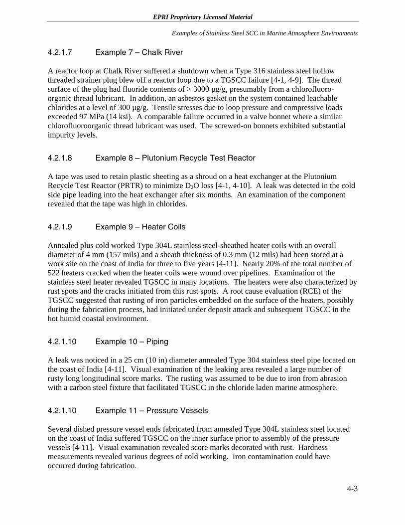
EPRI Proprietary Licensed Material
Examples of Stainless Steel SCC in Marine Atmosphere Environments
4.2.1.7 Example 7 – Chalk River
A reactor loop at Chalk River suffered a shutdown when a Type 316 stainless steel hollow threaded strainer plug blew off a reactor loop due to a TGSCC failure [4-1, 4-9]. The thread surface of the plug had fluoride contents of > 3000 µg/g, presumably from a chlorofluoro-organic thread lubricant. In addition, an asbestos gasket on the system contained leachable chlorides at a level of 300 µg/g. Tensile stresses due to loop pressure and compressive loads exceeded 97 MPa (14 ksi). A comparable failure occurred in a valve bonnet where a similar chlorofluoroorganic thread lubricant was used. The screwed-on bonnets exhibited substantial impurity levels.
4.2.1.8 Example 8 – Plutonium Recycle Test Reactor
A tape was used to retain plastic sheeting as a shroud on a heat exchanger at the Plutonium Recycle Test Reactor (PRTR) to minimize D2O loss [4-1, 4-10]. A leak was detected in the cold side pipe leading into the heat exchanger after six months. An examination of the component revealed that the tape was high in chlorides.
4.2.1.9 Example 9 – Heater Coils
Annealed plus cold worked Type 304L stainless steel-sheathed heater coils with an overall diameter of 4 mm (157 mils) and a sheath thickness of 0.3 mm (12 mils) had been stored at a work site on the coast of India for three to five years [4-11]. Nearly 20% of the total number of 522 heaters cracked when the heater coils were wound over pipelines. Examination of the stainless steel heater revealed TGSCC in many locations. The heaters were also characterized by rust spots and the cracks initiated from this rust spots. A root cause evaluation (RCE) of the TGSCC suggested that rusting of iron particles embedded on the surface of the heaters, possibly during the fabrication process, had initiated under deposit attack and subsequent TGSCC in the hot humid coastal environment.
4.2.1.10 Example 10 – Piping
A leak was noticed in a 25 cm (10 in) diameter annealed Type 304 stainless steel pipe located on the coast of India [4-11]. Visual examination of the leaking area revealed a large number of rusty long longitudinal score marks. The rusting was assumed to be due to iron from abrasion with a carbon steel fixture that facilitated TGSCC in the chloride laden marine atmosphere.
4.2.1.10 Example 11 – Pressure Vessels
Several dished pressure vessel ends fabricated from annealed Type 304L stainless steel located on the coast of India suffered TGSCC on the inner surface prior to assembly of the pressure vessels [4-11]. Visual examination revealed score marks decorated with rust. Hardness measurements revealed various degrees of cold working. Iron contamination could have occurred during fabrication.
4-3
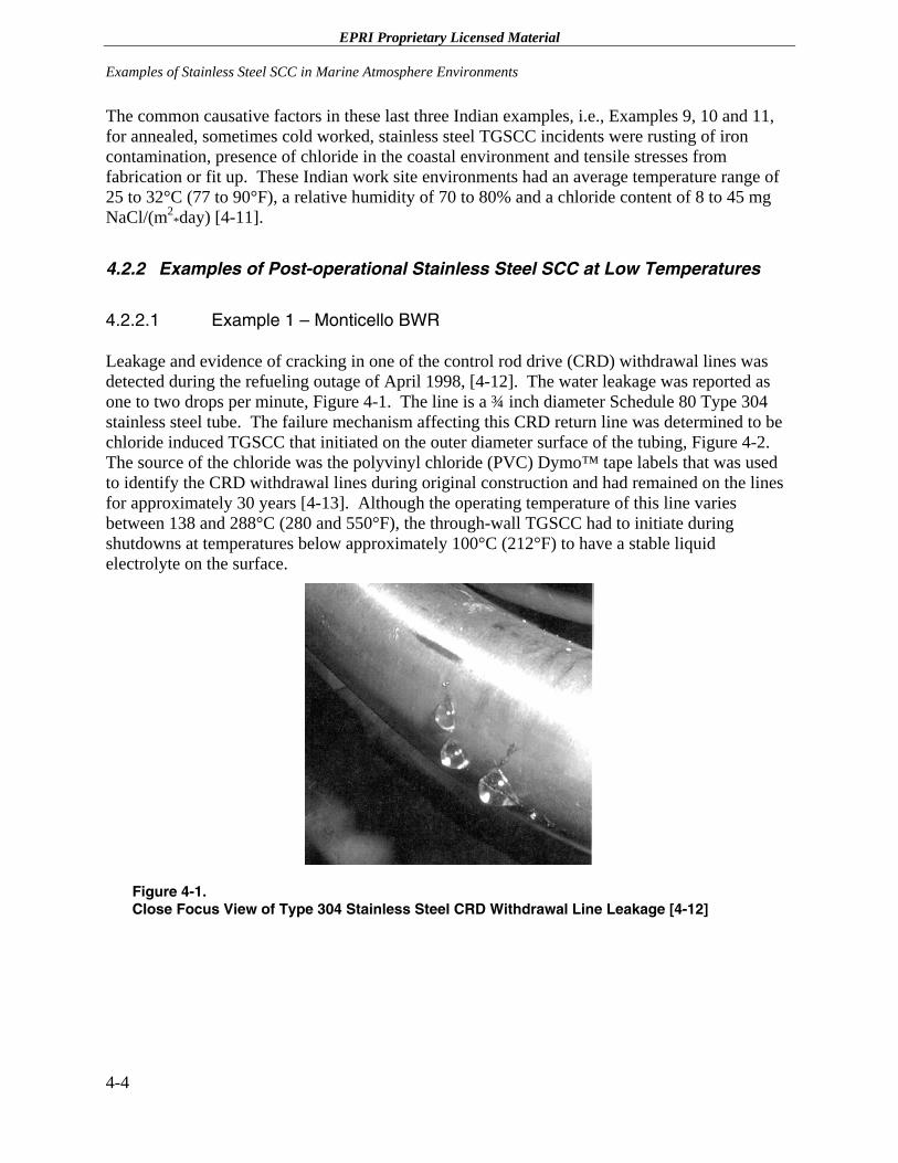
EPRI Proprietary Licensed Material Examples of Stainless Steel SCC in Marine Atmosphere Environments
The common causative factors in these last three Indian examples, i.e., Examples 9, 10 and 11, for annealed, sometimes cold worked, stainless steel TGSCC incidents were rusting of iron contamination, presence of chloride in the coastal environment and tensile stresses from fabrication or fit up. These Indian work site environments had an average temperature range of 25 to 32°C (77 to 90°F), a relative humidity of 70 to 80% and a chloride content of 8 to 45 mg NaCl/(m2
*day) [4-11].
4.2.2 Examples of Post-operational Stainless Steel SCC at Low Temperatures
4.2.2.1 Example 1 – Monticello BWR
Leakage and evidence of cracking in one of the control rod drive (CRD) withdrawal lines was detected during the refueling outage of April 1998, [4-12]. The water leakage was reported as one to two drops per minute, Figure 4-1. The line is a ¾ inch diameter Schedule 80 Type 304 stainless steel tube. The failure mechanism affecting this CRD return line was determined to be chloride induced TGSCC that initiated on the outer diameter surface of the tubing, Figure 4-2. The source of the chloride was the polyvinyl chloride (PVC) Dymo™ tape labels that was used to identify the CRD withdrawal lines during original construction and had remained on the lines for approximately 30 years [4-13]. Although the operating temperature of this line varies between 138 and 288°C (280 and 550°F), the through-wall TGSCC had to initiate during shutdowns at temperatures below approximately 100°C (212°F) to have a stable liquid electrolyte on the surface.
Figure 4-1. Close Focus View of Type 304 Stainless Steel CRD Withdrawal Line Leakage [4-12]
4-4
EPRI Proprietary Licensed Material
Examples of Stainless Steel SCC in Marine Atmosphere Environments
Figure 4-2. Close Focus View of the SCC on the Outer Surface of the CRD Withdrawal Line [4-12]
4.2.2.2 Example 2 - Urea Plant
Five failures of Type 304 L and 316L stainless steel piping and pressure vessels have been identified from 1986 to 2001 in several urea plants in Iran [4-14]. Investigations of five incidents indicated that the TGSCC initiated from outside surface, i.e., non process fluid side, under the piping insulation. The TGSCC was due to concentration of chloride in insulation that was wetted and impregnated in the prevailing marine environment at the various urea site locations.
4.2.2.3 Example 3 – Indoor Swimming Pools Ceiling Supports
Numerous very serious accidents involving ambient temperature SCC of austenitic stainless steel ceiling bolts/rods/wires supporting ceilings over indoor swimming pool have been reported [4-15]. For example, the collapse of a concrete ceiling at Uster, Switzerland in May 1987 resulted in 13 deaths. Since that incident SCC failures have been reported in the United Kingdom, Germany, Denmark and Sweden. The German failures resulted in a survey of 71 pools in Bavaria that revealed SCC in eight pools (four in Type 304 stainless steel and four in a titanium stabilized Type 316 stainless steel [DIN 1.4571]).
The operational changes identified for the occurrences of ambient SCC of these alloys are higher pool operating temperatures, i.e., 30 versus 21 ºC (86 versus 70 °F), higher pool usage and additional features such as fountains. All these modifications result in more dispersal of pool water into the atmosphere. Also, higher recirculation of pool water produces higher dissolved solids in the water and contaminants in the atmosphere. However, no mechanistic understanding
4-5
EPRI Proprietary Licensed Material Examples of Stainless Steel SCC in Marine Atmosphere Environments
of the phenomenon has been identified. It is interesting to note that all the SCC occurred in the atmosphere of indoor pools and no SCC was identified under immersed conditions or in the atmosphere associated with outdoor pools.
4.2.2.4 Example 4 – Assorted Fasteners
Numerous stainless steel fasteners have cracked due to SCC in marine environments. For example, two Type 303 stainless steel nuts suffered SCC after 14 years service holding the bonnet of a cast Alloy 20 valve located on a seawater corrosion test facility wharf [4-16]. Stainless steel nuts used on the atmospheric test racks at the LaQue Center at Kure Beach, NC have also suffered TGSCC. In both these examples, SCC was attributed to air- and spray-borne chlorides where cracking initiated in the threads, which suggests a possible contribution from crevice corrosion, at least in the initiation stage of the SCC mechanism.
SCC of Type 301 stainless steel band clamps have also been observed at the LaQue Center at Kure Beach [4-16]. Examination of the cold worked stainless steel clamps revealed that the inner shielded surface of the clamp was characterized by pitting corrosion and crevice corrosion adjacent to the SCC failure.
4.3 References
4-1 S. H. Bush and R. L. Dillon, “Stress Corrosion in Nuclear Systems,” Proceedings of Conference “Stress Corrosion Cracking and Hydrogen Embrittlement of Iron Based Alloys,” Unieux Firminy, France, June 12-16 1973, NACE, 1977, p 61.
4-2 Amendment 13, Philadelphia Electric Company, Peach Bottom Atomic Power Station, Docket 50-171, 1966.
4-3 Amendment 37, Oyster Creek Nuclear Power Plant, “Reactor Vessel Repair Program - Additional Information,” Docket 50-219, April 15, 1968. Amendment 40, Oyster Creek Nuclear Power Plant. Docket 50-219, August 30, 1968.
4-4 M. Dayal, “Performance of the Tarapur Atomic Power Station,” A/CONF-49/P/526 UN 1971.
4-5 E. G. Bohlmann and G. M. Adamson, “Stress Corrosion Cracking Problems in the Homogeneous Reactor Test,” CF-57-1-143, January 31, 1957.
4-6 J. A. Leppard, “Review of SCTI Bellows Failure,” NAA-SR-MEMO 11970, May 26, 1966.
4-7 L. D. Schaffer and J. A. Klepfer, “Investigation of the Effects of Wet, Chloride-Bearing Thermal Insulation on Austenitic Steel Pipe,” ORNL-TM-14, November 1, 1961.
4-8 S. P. Rideout and R. F. Mittelberg, “Factors Controlling Chloride Stress Corrosion of Type 304 Stainless Steel,” CONF-778-3, October 1964.
4-6
EPRI Proprietary Licensed Material
Examples of Stainless Steel SCC in Marine Atmosphere Environments
4-9 S. P. Gibson, et al., “Chloride Stress Corrosion Cracking in Threaded 300 Series Stainless Steel Components,” AECL-2878, May 1967.
4-10 R. V. Dulen, “Tubing Failure in the PRTR Rupture Monitor Heat Exchanger (HX-5),” HW-82888, July 1964.
4-11 J. B. Gnanamoorthy, “Stress Corrosion Cracking of Unsensitized Stainless Steels in Ambient Temperature Coastal Atmosphere,” Materials Performance, Vol. 29, No. 12, December 1990, p. 63.
4-12 D. E. Delwiche, “Assessment of Cracking in CRD Insert and Withdrawal Lines at Monticello,” SIR-99-106, September 1999.
4-13 B. M. Gordon, “Effect of Dymo™ Tape on the Structural Integrity of Monticello CRD Lines,” SIR-02-002, January 2002.
4-14 A. H. Faraji, “External SCC Phenomena of Austenitic Stainless Steel in Urea Plants,” paper 02439 presented at Corrosion 2002, Denver, CO, NACE, April 7-11, 2002.
4-15 J. W. Oldfield and B. Todd, “Ambient Temperature Stress Corrosion Cracking of Austenitic Stainless Steels in Swimming Pools,” Material Performance, Vol. 29, No. 12, December 1990, p. 57.
4-16 R. M. Kain, “Marine Atmosphere Stress Corrosion Cracking of Austenitic Stainless Steel,” Material Performance, Vol. 29, No. 12, December 1990, p. 60
.
4-7

EPRI Proprietary Licensed Material
5 U. S. SPENT FUEL STORAGE SITES
5.1 Introduction
As discussed earlier in this report, the NISA/CRIEPI presentation suggests that seaside storage of spent nuclear fuel in austenitic stainless steel storage canisters may suffer incidents of SCC, which could lead to through-wall penetration. Specifically, the areas of the canisters that would be susceptible to SCC in a marine environment are the shell fabrication welds and the shell containment field closure welds. These welds are left in the as-welded condition, and, therefore, have residual tensile stresses that could promote SCC.
5.2 U. S. Sites
Table 5-1 presents a listing of the operating Independent Spent Fuel Storage Installations (ISFSIs), the utility owners/operators, plant sites, cask storage systems, number of loaded casks/canisters, and whether the canisters are stainless steel. As of June 30, 2005, there were 32 ISFSIs in operation, i.e., containing fuel canisters loaded with spent fuel. Of these, 29 contain loaded canisters that are made of austenitic stainless steel. Of the 29 facilities with loaded stainless steel canisters, the only site located adjacent to the ocean is the San Onofre site.
The parameters that contribute to the propensity for SCC, as discussed in earlier sections of this report, are:
1. Moisture and time of wetness
2. Airborne contaminants (e.g., chlorides, sulfur dioxide, carbon dioxide, etc.)
3. Distance, elevation, orientation and shelter
4. Temperature
5. Sunlight and wind
6. Cold worked microstructure
7. Weld and/or furnace sensitized microstructure
8. Surface iron contamination
5-1
EPRI Proprietary Licensed Material U. S. Spent Fuel Storage Sites
9. Crevices and subsequent crevice corrosion
10. Pitting corrosion
Of the above, the main differentiating parameters are parameters 1 and 2. Moisture and time of wetness are affected by the geographic location of the facility and the age of the facility. Facilities located in high humidity regions with higher rainfall would experience more moisture and time of wetness than facilities with lower humidity and rainfall. Also, canisters that have been loaded for longer time periods would generally have been exposed to more moisture and wetness cycles. Based on the discussion in Section 2.3 of this report, areas with higher airborne contaminants, particularly concentrations of chlorides in the rainwater are more aggressive with regard to SCC. Figure 2-1 shows the average chloride concentration in rainwater in the United States. Dust and other trace minerals also present in the air that would deposit on the canisters along with chlorides from the sea salt may either enhance or mitigate SCC. These additional chemical effects have not, as yet, been considered rigorously.
The remaining parameters are not significantly different among the facilities. All the canisters are stored within fully enclosed concrete horizontal storage modules. The canisters are exposed to the environment via screened air inlet and outlet vents in the module, which are used for circulating air to transfer heat from the canister to the atmosphere.
The temperature of the canisters varies depending on the type of fuel stored. More recently designed canisters are able to store fuel with higher heat loads than older designs. As discussed in Section 2.5.3, dry, i.e., non-aqueous, corrosion is of no consequence to the materials used in the spent fuel storage canister. Aqueous corrosion processes only commence at temperatures below the boiling point of any solution that may condense on the metal surface. The relative humidity must be greater than the deliquescence points of any salts present to obtain a viable electrolyte. As a result, the presence of a liquid phase on the canister surface is possible only when the surface temperature is low enough. At those temperatures, uniform corrosion rates of stainless are not considered significant, but initiation of pitting and crevice corrosion cannot be ruled out as discussed in Section 2.5.2. With the reservations noted in Section 2.5.2.3, stress corrosion cracking of types 304 and 316 stainless steels may not occur at a temperature below 60°C. For purposes of this discussion, the temperature parameter is considered to be essentially the same for all sites, because it is simply a matter of time before similar temperature regimes are established.
The degree of sunlight and wind is generally not a factor for the canisters since they are completely enclosed by the concrete modules. Average wind speed and direction near coastal sites may play a secondary factor related to the extent to which generally higher coastal airborne chloride levels can be moved farther inland.
The factors associated with the physical condition of the canister material, parameters 6 through 10 in the above list, are considered the same for all canisters because the materials and the construction methods are generally the same. The canister cylinders are all fabricated from thick stainless steel plate [minimum wall thickness of 16 mm (0.625 inch)] with either one longitudinal full penetration butt weld, or two plates each with a longitudinal full penetration butt
5-2
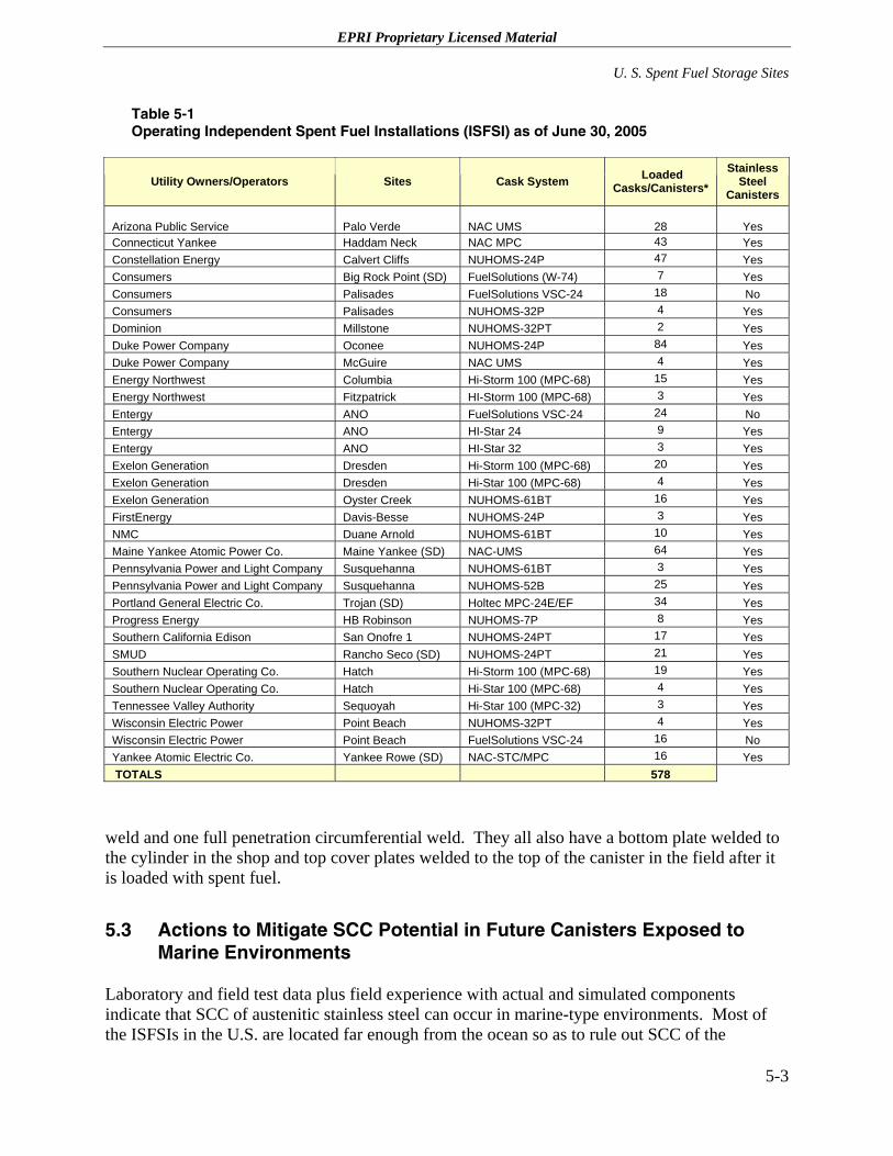
EPRI Proprietary Licensed Material
U. S. Spent Fuel Storage Sites
Table 5-1 Operating Independent Spent Fuel Installations (ISFSI) as of June 30, 2005
Utility Owners/Operators Sites Cask System Loaded Casks/Canisters*
Stainless Steel
Canisters
Arizona Public Service Palo Verde NAC UMS
28 Yes Connecticut Yankee Haddam Neck NAC MPC 43 Yes Constellation Energy Calvert Cliffs NUHOMS-24P 47 Yes Consumers Big Rock Point (SD) FuelSolutions (W-74) 7 Yes Consumers Palisades FuelSolutions VSC-24 18 No Consumers Palisades NUHOMS-32P 4 Yes Dominion Millstone NUHOMS-32PT 2 Yes Duke Power Company Oconee NUHOMS-24P 84 Yes Duke Power Company McGuire NAC UMS 4 Yes Energy Northwest Columbia Hi-Storm 100 (MPC-68) 15 Yes Energy Northwest Fitzpatrick HI-Storm 100 (MPC-68) 3 Yes Entergy ANO FuelSolutions VSC-24 24 No Entergy ANO HI-Star 24 9 Yes Entergy ANO HI-Star 32 3 Yes Exelon Generation Dresden Hi-Storm 100 (MPC-68) 20 Yes Exelon Generation Dresden Hi-Star 100 (MPC-68) 4 Yes Exelon Generation Oyster Creek NUHOMS-61BT 16 Yes FirstEnergy Davis-Besse NUHOMS-24P 3 Yes NMC Duane Arnold NUHOMS-61BT 10 Yes Maine Yankee Atomic Power Co. Maine Yankee (SD) NAC-UMS 64 Yes Pennsylvania Power and Light Company Susquehanna NUHOMS-61BT 3 Yes Pennsylvania Power and Light Company Susquehanna NUHOMS-52B 25 Yes Portland General Electric Co. Trojan (SD) Holtec MPC-24E/EF 34 Yes Progress Energy HB Robinson NUHOMS-7P 8 Yes Southern California Edison San Onofre 1 NUHOMS-24PT 17 Yes SMUD Rancho Seco (SD) NUHOMS-24PT 21 Yes Southern Nuclear Operating Co. Hatch Hi-Storm 100 (MPC-68) 19 Yes Southern Nuclear Operating Co. Hatch Hi-Star 100 (MPC-68) 4 Yes Tennessee Valley Authority Sequoyah Hi-Star 100 (MPC-32) 3 Yes Wisconsin Electric Power Point Beach NUHOMS-32PT 4 Yes Wisconsin Electric Power Point Beach FuelSolutions VSC-24 16 No Yankee Atomic Electric Co. Yankee Rowe (SD) NAC-STC/MPC 16 Yes TOTALS 578
weld and one full penetration circumferential weld. They all also have a bottom plate welded to the cylinder in the shop and top cover plates welded to the top of the canister in the field after it is loaded with spent fuel.
5.3 Actions to Mitigate SCC Potential in Future Canisters Exposed to Marine Environments
Laboratory and field test data plus field experience with actual and simulated components indicate that SCC of austenitic stainless steel can occur in marine-type environments. Most of the ISFSIs in the U.S. are located far enough from the ocean so as to rule out SCC of the
5-3
EPRI Proprietary Licensed Material U. S. Spent Fuel Storage Sites
stainless steel canister as a concern. The only U.S. ISFSI adjacent to the ocean has favorable characteristics with regard to low average relative humidity. On the other hand, a small number of Eastern ISFSIs located on bays and estuaries with a mixture of fresh and salt water may, or may not, have enough characteristics that would classify them as “marine” environments. For these sites, data, such as local airborne material sampling, supplemented by corrosion modeling would be required for such a determination.
A prudent approach for future canister systems that will be exposed to environments having attributes approaching those of a marine environment would be to consider SCC mitigating measures. As discussed in Section 1.2 of this report, the three necessary conditions for SCC are tensile stress, susceptible material, and corrosive environment. One of these conditions, corrosive environment, is always present for canisters exposed to marine environments. Therefore, any potential SCC mitigating measures must eliminate or minimize one or both of the other two necessary conditions. Appendix E of this report discusses candidate materials of construction for spent fuel storage canisters exposed to marine environments. This discussion identifies materials other than stainless steel for canister construction that have higher resistance to SCC, but, in general, they are not as well established and significantly more expensive than stainless steel. The discussion suggests that nickel-based alloy 22 is a likely alternative because of the research done to date on this alloy in expected repository environments. It cautions, however, that additional modeling in addition to laboratory research is required since laboratory test techniques have inadequate sensitivity to crack growth for the prediction of acceptable long term performance. Based on these discussions, it appears that mitigation of SCC via material changes for spent fuel storage canisters is not practical for the near future.
Appendix B discusses tensile stress mitigation technologies that could be investigated and potentially applied to spent fuel storage canisters during the fabrication process. While implementation of stress mitigation would increase the fabrication cost of canisters, the potential positive effects for SCC mitigation could justify the additional cost. ISFSI licensees who are interested in minimizing their risk for SCC in canisters could consider implementing stress mitigation of weldments during fabrication.
Stress mitigation technologies identified in Appendix B are not likely to be practical for the closure welds performed after canister loading. However, the canister has two cover plates, each of which is welded to the canister shell. Since the inner cover plate closure weld is not exposed to the environment, it represents a redundant closure weld that would only be exposed to the marine environment if the outer cover plate weld failed. This redundancy reduces any risk of the canister leaking due to SCC.
5-4
EPRI Proprietary Licensed Material
6 CONCLUSION
6.1 Marine Atmosphere SCC Discussion
Laboratory and field test data plus field experience with actual and simulated components indicate that the SCC of austenitic stainless steel can occur in marine-type environments. Therefore, SCC concerns for spent fuel storage canisters identified in the NISA/CRIEPI presentation are warranted.
As noted in Section 2, the SCC propensity of austenitic stainless steels in marine environments is affected by all the following often interrelated factors:
1. Moisture and time of wetness
2. Airborne contaminants (e.g., chlorides, sulfur dioxide, carbon dioxide, etc.)
3. Distance, elevation, orientation and shelter
4. Temperature
5. Sunlight and wind for unsheltered structures
The data on the SCC propensities of austenitic stainless steels in marine environments also indicate that SCC is exacerbated by the presence of the following factors:
1. Cold worked microstructure
2. Weld and/or furnace sensitized microstructure
3. Surface iron contamination
4. Crevices and subsequent crevice corrosion
5. Pitting corrosion
6-1
EPRI Proprietary Licensed Material Conclusion
6.2 NISA and CRIEPI Test Program
There are two ongoing corrosion studies, i.e., Items 1 and 3, in the Japanese spent fuel storage canisters program as presented in Appendix A. Item 1 involves determining the “threshold” salt density for general corrosion, i.e., rusting, and for SCC initiation, while Item 3 is a crack growth rate measurement program. Both programs use specimens fabricated from Type 304L austenitic stainless steel (19 Cr – 10 Ni), a very high chromium Type 329J4L duplex stainless steel (28 Cr – 6 Ni – 3 Mo – N), and a high molybdenum super austenitic stainless steel ASTM SA240 S31254 (20 Cr – 18 Ni – 6 Mo – N). Item 1’s tests are conducted on plate for general corrosion and on flat dog-bone tensile specimens for SCC initiation studies while Item 3’s testing is performed on 12.7 mm (0.5 T) compact tension fracture mechanics specimens at stress intensities of 5 to 40 MPa√m (4.5 to 36.4 ksi√in) using the DCPD technique. As discussed in Section 1.2.1, DCPD is the only accurate technique for measuring real-time crack growth rates.
Both test programs are considered very worthwhile. It is recommended that the results of these SCC initiation tensile tests be compared to the pressurized tube studies discussed in Section 3. The evaluation of the effect of iron powder on SCC initiation should also be considered to be included in this study to determine if only stainless steel equipment should be used to handle the spent fuel storage canisters.
The proposed Item 3 marine environment SCC propagation test program will provide very valuable data. Although there is a very significant amount of data on the crack growth rates of austenitic stainless steels in high temperature water environments, there is essentially no DCPD crack growth rate data obtained in low temperature marine environments. This data can be used to calculate canister through-wall penetrations based on assumed initial flaws and stress profiles.
Finally, it should be noted that the Yucca Mountain Project has produced extensive amounts of information on the factors affecting SCC of spent fuel storage canisters, crack growth rates, residual stress profiles, leak rates through SCC cracks, etc.
6-2
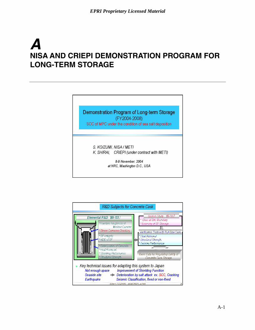
EPRI Proprietary Licensed Material
A NISA AND CRIEPI DEMONSTRATION PROGRAM FOR LONG-TERM STORAGE
A-1
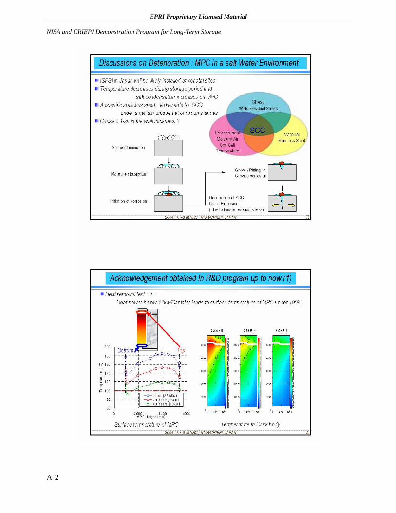
EPRI Proprietary Licensed Material NISA and CRIEPI Demonstration Program for Long-Term Storage
A-2
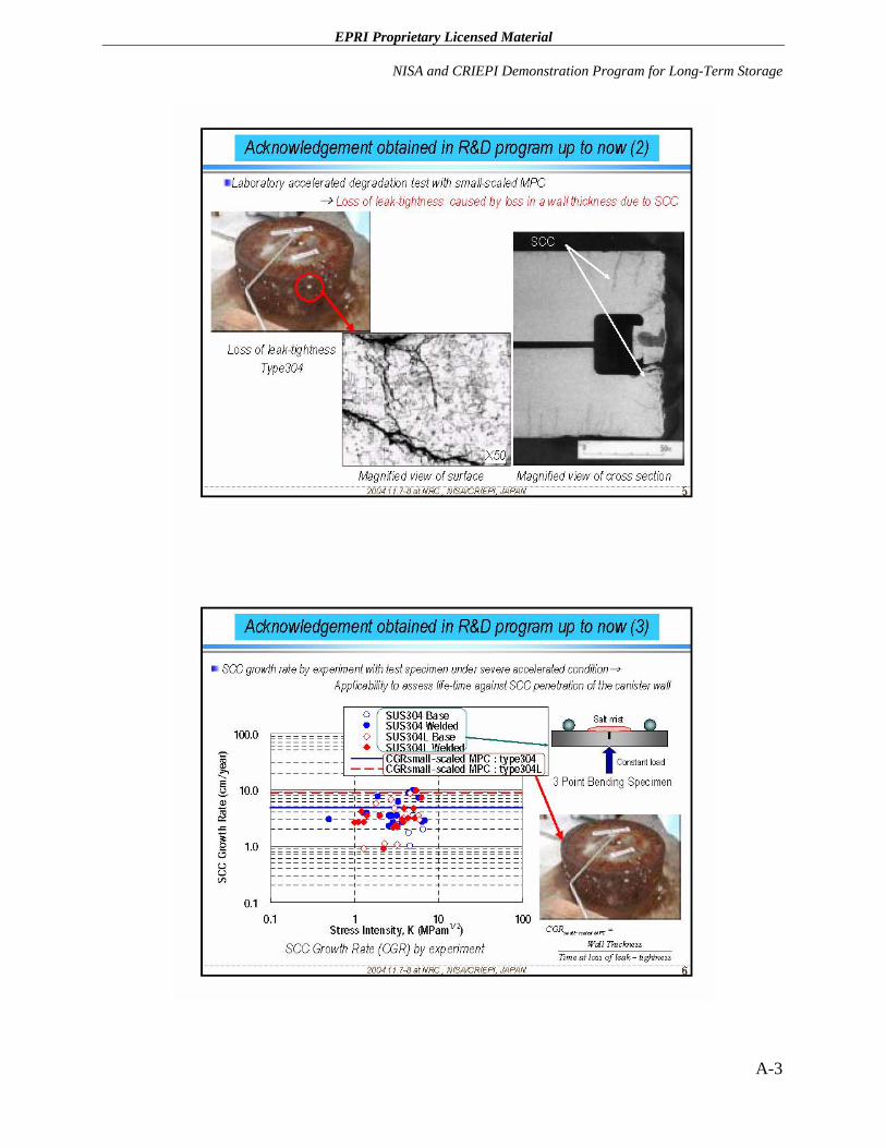
EPRI Proprietary Licensed Material
NISA and CRIEPI Demonstration Program for Long-Term Storage
A-3
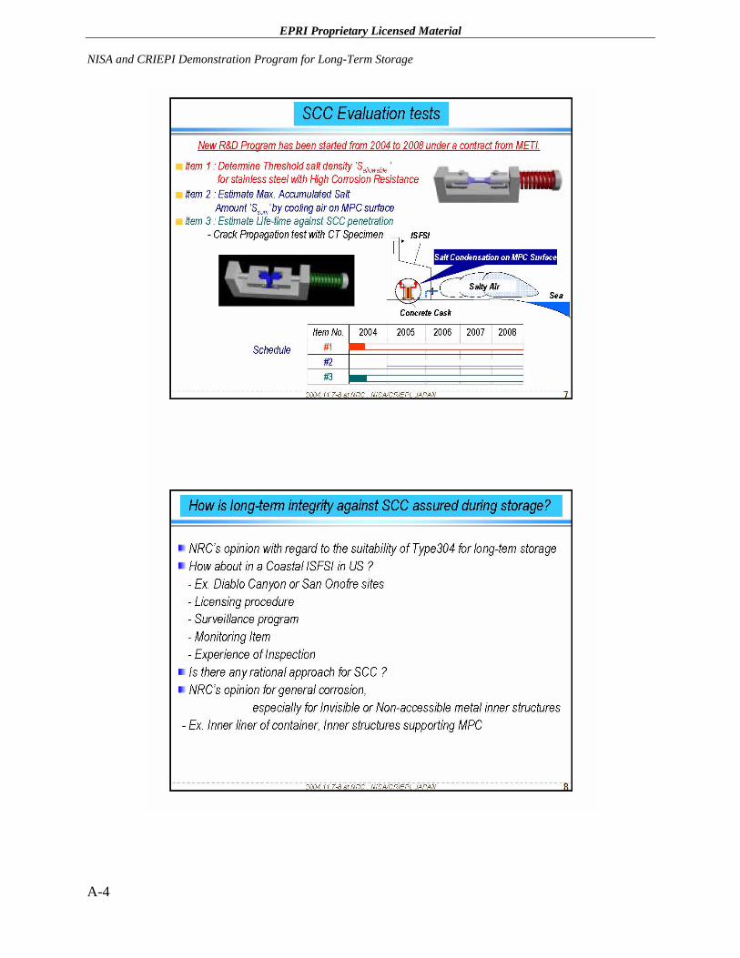
EPRI Proprietary Licensed Material NISA and CRIEPI Demonstration Program for Long-Term Storage
A-4
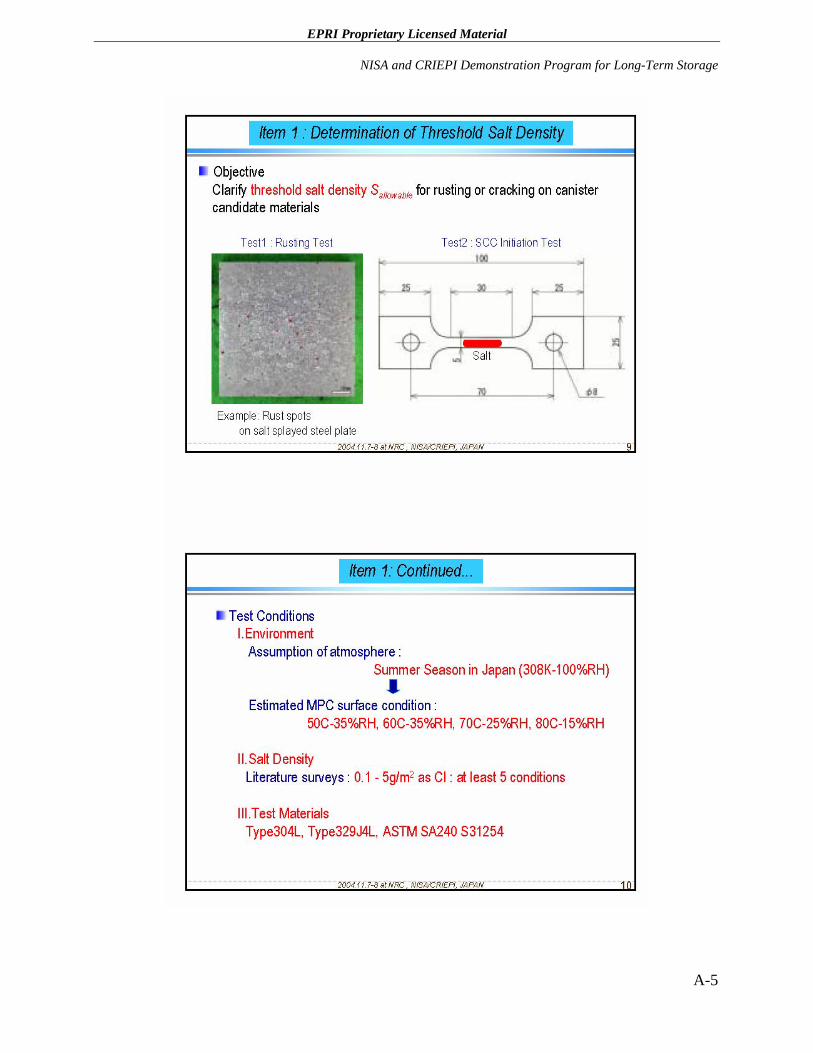
EPRI Proprietary Licensed Material
NISA and CRIEPI Demonstration Program for Long-Term Storage
A-5
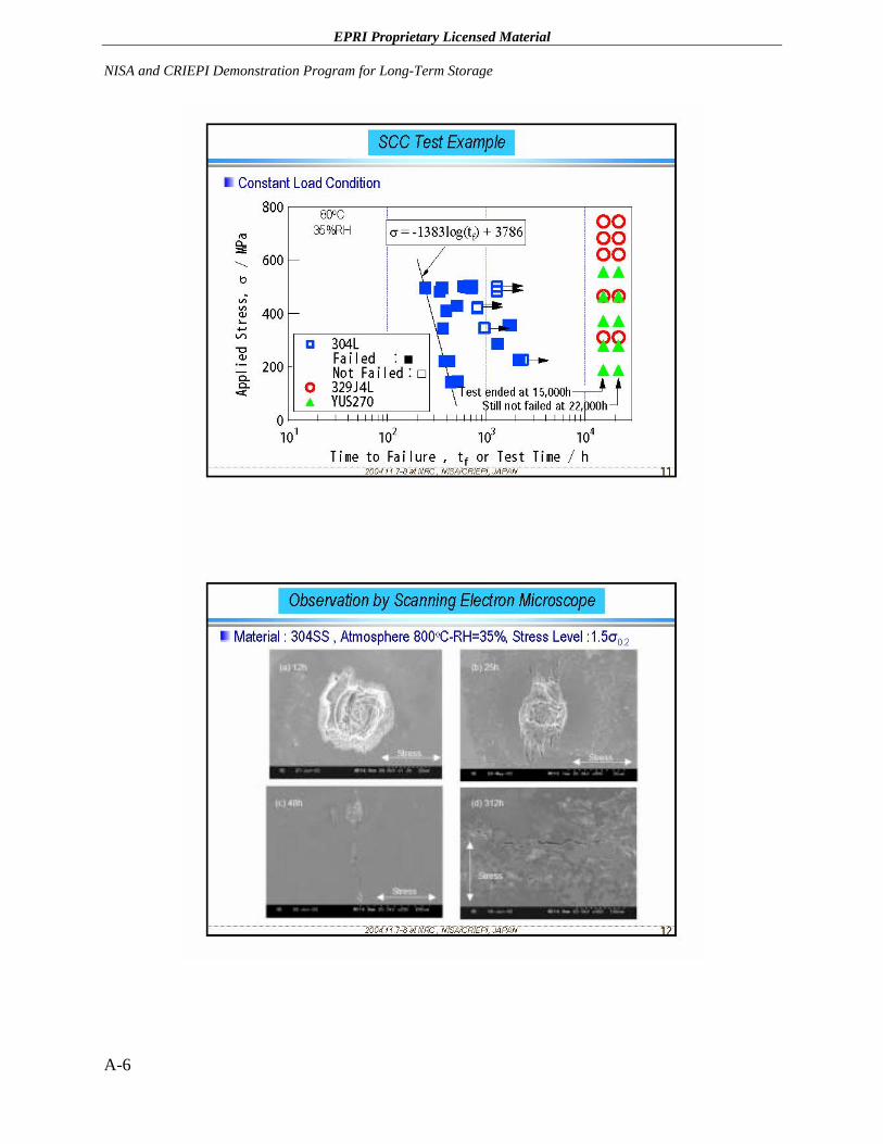
EPRI Proprietary Licensed Material NISA and CRIEPI Demonstration Program for Long-Term Storage
A-6
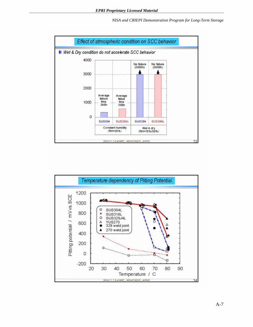
EPRI Proprietary Licensed Material
NISA and CRIEPI Demonstration Program for Long-Term Storage
A-7
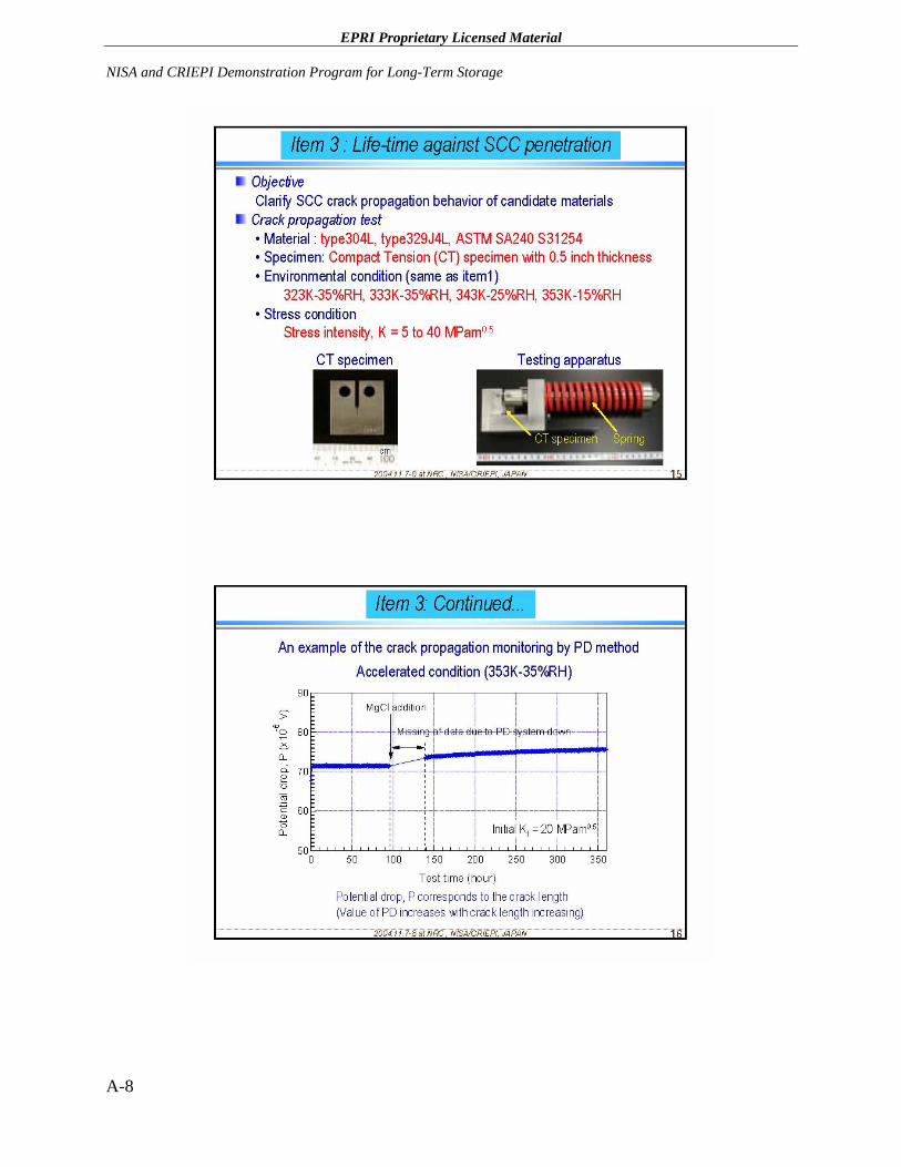
EPRI Proprietary Licensed Material NISA and CRIEPI Demonstration Program for Long-Term Storage
A-8
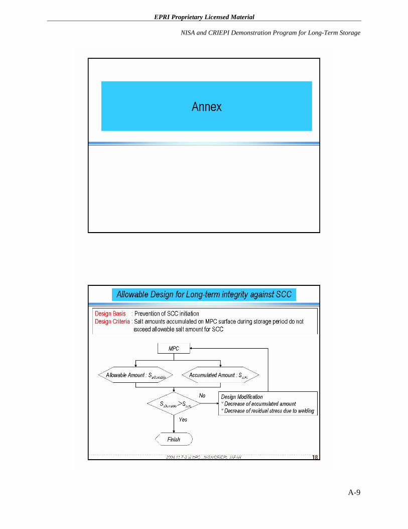
EPRI Proprietary Licensed Material
NISA and CRIEPI Demonstration Program for Long-Term Storage
A-9
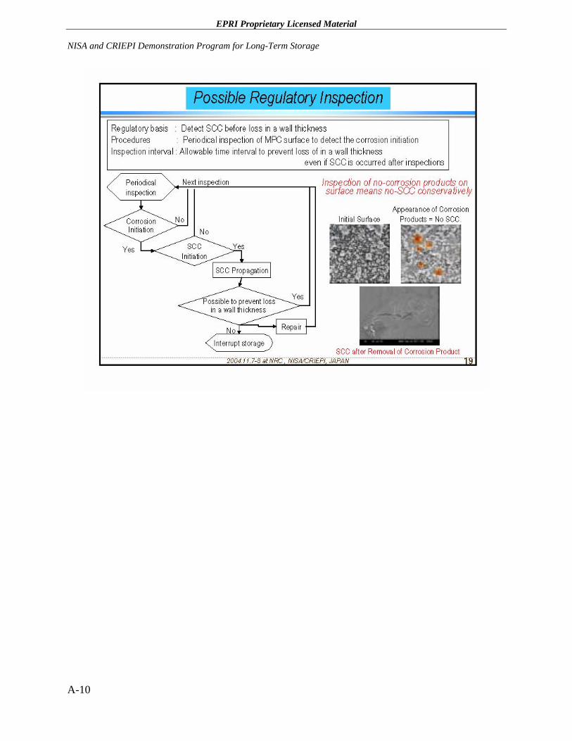
EPRI Proprietary Licensed Material NISA and CRIEPI Demonstration Program for Long-Term Storage
A-10
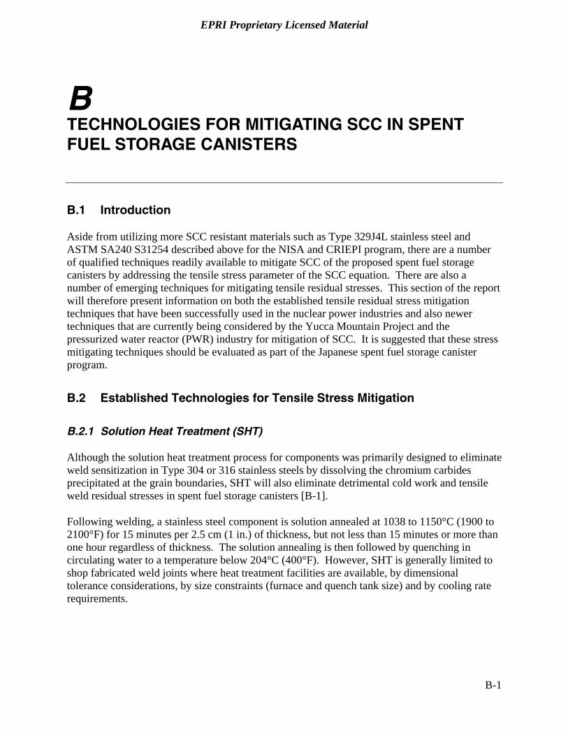
EPRI Proprietary Licensed Material
B TECHNOLOGIES FOR MITIGATING SCC IN SPENT FUEL STORAGE CANISTERS
B.1 Introduction
Aside from utilizing more SCC resistant materials such as Type 329J4L stainless steel and ASTM SA240 S31254 described above for the NISA and CRIEPI program, there are a number of qualified techniques readily available to mitigate SCC of the proposed spent fuel storage canisters by addressing the tensile stress parameter of the SCC equation. There are also a number of emerging techniques for mitigating tensile residual stresses. This section of the report will therefore present information on both the established tensile residual stress mitigation techniques that have been successfully used in the nuclear power industries and also newer techniques that are currently being considered by the Yucca Mountain Project and the pressurized water reactor (PWR) industry for mitigation of SCC. It is suggested that these stress mitigating techniques should be evaluated as part of the Japanese spent fuel storage canister program.
B.2 Established Technologies for Tensile Stress Mitigation
B.2.1 Solution Heat Treatment (SHT)
Although the solution heat treatment process for components was primarily designed to eliminate weld sensitization in Type 304 or 316 stainless steels by dissolving the chromium carbides precipitated at the grain boundaries, SHT will also eliminate detrimental cold work and tensile weld residual stresses in spent fuel storage canisters [B-1].
Following welding, a stainless steel component is solution annealed at 1038 to 1150°C (1900 to 2100°F) for 15 minutes per 2.5 cm (1 in.) of thickness, but not less than 15 minutes or more than one hour regardless of thickness. The solution annealing is then followed by quenching in circulating water to a temperature below 204°C (400°F). However, SHT is generally limited to shop fabricated weld joints where heat treatment facilities are available, by dimensional tolerance considerations, by size constraints (furnace and quench tank size) and by cooling rate requirements.
B-1
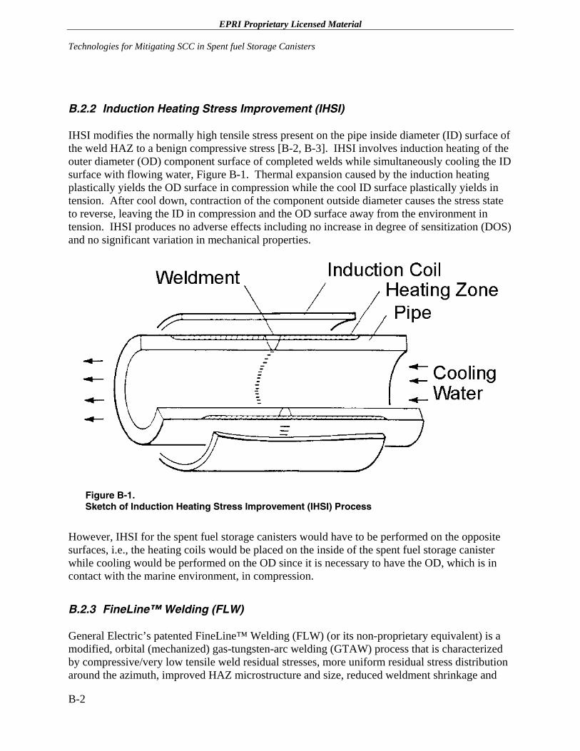
EPRI Proprietary Licensed Material Technologies for Mitigating SCC in Spent fuel Storage Canisters
B.2.2 Induction Heating Stress Improvement (IHSI)
IHSI modifies the normally high tensile stress present on the pipe inside diameter (ID) surface of the weld HAZ to a benign compressive stress [B-2, B-3]. IHSI involves induction heating of the outer diameter (OD) component surface of completed welds while simultaneously cooling the ID surface with flowing water, Figure B-1. Thermal expansion caused by the induction heating plastically yields the OD surface in compression while the cool ID surface plastically yields in tension. After cool down, contraction of the component outside diameter causes the stress state to reverse, leaving the ID in compression and the OD surface away from the environment in tension. IHSI produces no adverse effects including no increase in degree of sensitization (DOS) and no significant variation in mechanical properties.
Figure B-1. Sketch of Induction Heating Stress Improvement (IHSI) Process
However, IHSI for the spent fuel storage canisters would have to be performed on the opposite surfaces, i.e., the heating coils would be placed on the inside of the spent fuel storage canister while cooling would be performed on the OD since it is necessary to have the OD, which is in contact with the marine environment, in compression.
B.2.3 FineLine™ Welding (FLW)
General Electric’s patented FineLine™ Welding (FLW) (or its non-proprietary equivalent) is a modified, orbital (mechanized) gas-tungsten-arc welding (GTAW) process that is characterized by compressive/very low tensile weld residual stresses, more uniform residual stress distribution around the azimuth, improved HAZ microstructure and size, reduced weldment shrinkage and
B-2
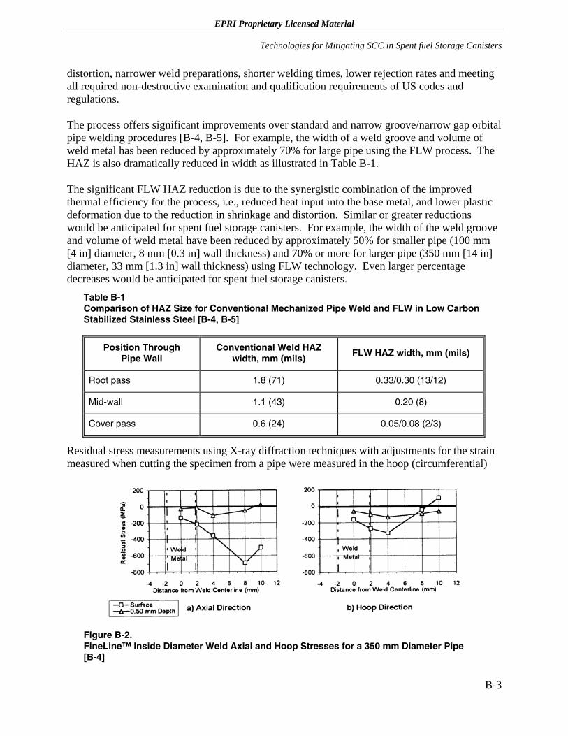
EPRI Proprietary Licensed Material
Technologies for Mitigating SCC in Spent fuel Storage Canisters
distortion, narrower weld preparations, shorter welding times, lower rejection rates and meeting all required non-destructive examination and qualification requirements of US codes and regulations.
The process offers significant improvements over standard and narrow groove/narrow gap orbital pipe welding procedures [B-4, B-5]. For example, the width of a weld groove and volume of weld metal has been reduced by approximately 70% for large pipe using the FLW process. The HAZ is also dramatically reduced in width as illustrated in Table B-1.
The significant FLW HAZ reduction is due to the synergistic combination of the improved thermal efficiency for the process, i.e., reduced heat input into the base metal, and lower plastic deformation due to the reduction in shrinkage and distortion. Similar or greater reductions would be anticipated for spent fuel storage canisters. For example, the width of the weld groove and volume of weld metal have been reduced by approximately 50% for smaller pipe (100 mm [4 in] diameter, 8 mm [0.3 in] wall thickness) and 70% or more for larger pipe (350 mm [14 in] diameter, 33 mm [1.3 in] wall thickness) using FLW technology. Even larger percentage decreases would be anticipated for spent fuel storage canisters.
Table B-1 Comparison of HAZ Size for Conventional Mechanized Pipe Weld and FLW in Low Carbon Stabilized Stainless Steel [B-4, B-5]
Position Through Pipe Wall
Conventional Weld HAZ width, mm (mils)
FLW HAZ width, mm (mils)
Root pass 1.8 (71) 0.33/0.30 (13/12)
Mid-wall 1.1 (43) 0.20 (8)
Cover pass 0.6 (24) 0.05/0.08 (2/3)
Residual stress measurements using X-ray diffraction techniques with adjustments for the strain measured when cutting the specimen from a pipe were measured in the hoop (circumferential)
Figure B-2. FineLine™ Inside Diameter Weld Axial and Hoop Stresses for a 350 mm Diameter Pipe [B-4]
B-3
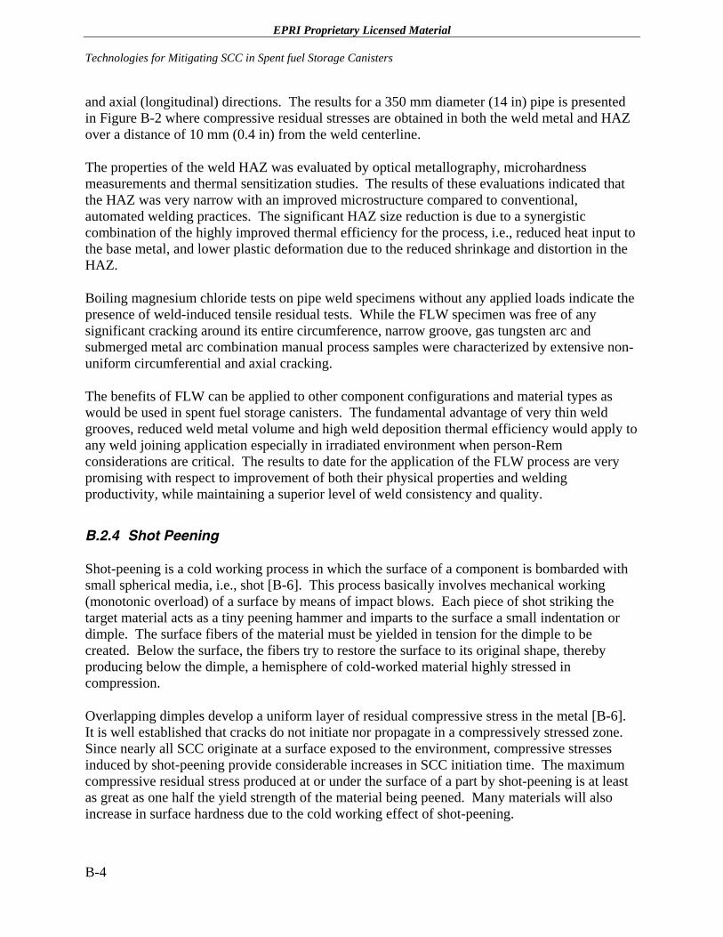
EPRI Proprietary Licensed Material Technologies for Mitigating SCC in Spent fuel Storage Canisters
and axial (longitudinal) directions. The results for a 350 mm diameter (14 in) pipe is presented in Figure B-2 where compressive residual stresses are obtained in both the weld metal and HAZ over a distance of 10 mm (0.4 in) from the weld centerline.
The properties of the weld HAZ was evaluated by optical metallography, microhardness measurements and thermal sensitization studies. The results of these evaluations indicated that the HAZ was very narrow with an improved microstructure compared to conventional, automated welding practices. The significant HAZ size reduction is due to a synergistic combination of the highly improved thermal efficiency for the process, i.e., reduced heat input to the base metal, and lower plastic deformation due to the reduced shrinkage and distortion in the HAZ.
Boiling magnesium chloride tests on pipe weld specimens without any applied loads indicate the presence of weld-induced tensile residual tests. While the FLW specimen was free of any significant cracking around its entire circumference, narrow groove, gas tungsten arc and submerged metal arc combination manual process samples were characterized by extensive non-uniform circumferential and axial cracking.
The benefits of FLW can be applied to other component configurations and material types as would be used in spent fuel storage canisters. The fundamental advantage of very thin weld grooves, reduced weld metal volume and high weld deposition thermal efficiency would apply to any weld joining application especially in irradiated environment when person-Rem considerations are critical. The results to date for the application of the FLW process are very promising with respect to improvement of both their physical properties and welding productivity, while maintaining a superior level of weld consistency and quality.
B.2.4 Shot Peening
Shot-peening is a cold working process in which the surface of a component is bombarded with small spherical media, i.e., shot [B-6]. This process basically involves mechanical working (monotonic overload) of a surface by means of impact blows. Each piece of shot striking the target material acts as a tiny peening hammer and imparts to the surface a small indentation or dimple. The surface fibers of the material must be yielded in tension for the dimple to be created. Below the surface, the fibers try to restore the surface to its original shape, thereby producing below the dimple, a hemisphere of cold-worked material highly stressed in compression.
Overlapping dimples develop a uniform layer of residual compressive stress in the metal [B-6]. It is well established that cracks do not initiate nor propagate in a compressively stressed zone. Since nearly all SCC originate at a surface exposed to the environment, compressive stresses induced by shot-peening provide considerable increases in SCC initiation time. The maximum compressive residual stress produced at or under the surface of a part by shot-peening is at least as great as one half the yield strength of the material being peened. Many materials will also increase in surface hardness due to the cold working effect of shot-peening.
B-4
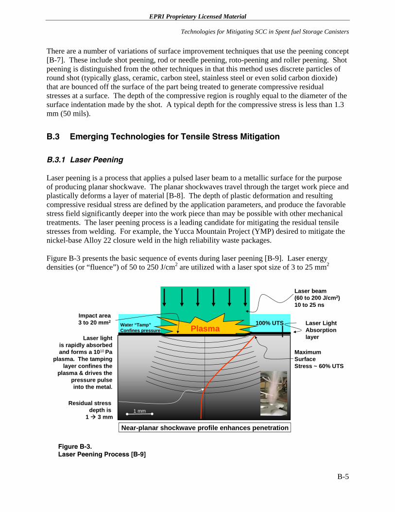
EPRI Proprietary Licensed Material
Technologies for Mitigating SCC in Spent fuel Storage Canisters
There are a number of variations of surface improvement techniques that use the peening concept [B-7]. These include shot peening, rod or needle peening, roto-peening and roller peening. Shot peening is distinguished from the other techniques in that this method uses discrete particles of round shot (typically glass, ceramic, carbon steel, stainless steel or even solid carbon dioxide) that are bounced off the surface of the part being treated to generate compressive residual stresses at a surface. The depth of the compressive region is roughly equal to the diameter of the surface indentation made by the shot. A typical depth for the compressive stress is less than 1.3 mm (50 mils).
B.3 Emerging Technologies for Tensile Stress Mitigation
B.3.1 Laser Peening
Laser peening is a process that applies a pulsed laser beam to a metallic surface for the purpose of producing planar shockwave. The planar shockwaves travel through the target work piece and plastically deforms a layer of material [B-8]. The depth of plastic deformation and resulting compressive residual stress are defined by the application parameters, and produce the favorable stress field significantly deeper into the work piece than may be possible with other mechanical treatments. The laser peening process is a leading candidate for mitigating the residual tensile stresses from welding. For example, the Yucca Mountain Project (YMP) desired to mitigate the nickel-base Alloy 22 closure weld in the high reliability waste packages.
Figure B-3 presents the basic sequence of events during laser peening [B-9]. Laser energy densities (or “fluence”) of 50 to 250 J/cm2 are utilized with a laser spot size of 3 to 25 mm2
Near-planar shockwave profile enhances penetration
MaximumSurfaceStress ~ 60% UTS
Impact area3 to 20 mm2
Residual stress depth is
1 3 mm
100% UTS
Laser beam(60 to 200 J/cm2)10 to 25 ns
1 mm
PlasmaWater “Tamp”Confines pressure
Laser Light AbsorptionlayerLaser light
is rapidly absorbed and forms a 1010 Pa
plasma. The tamping layer confines the
plasma & drives the pressure pulse into the metal.
Figure B-3. Laser Peening Process [B-9]
B-5
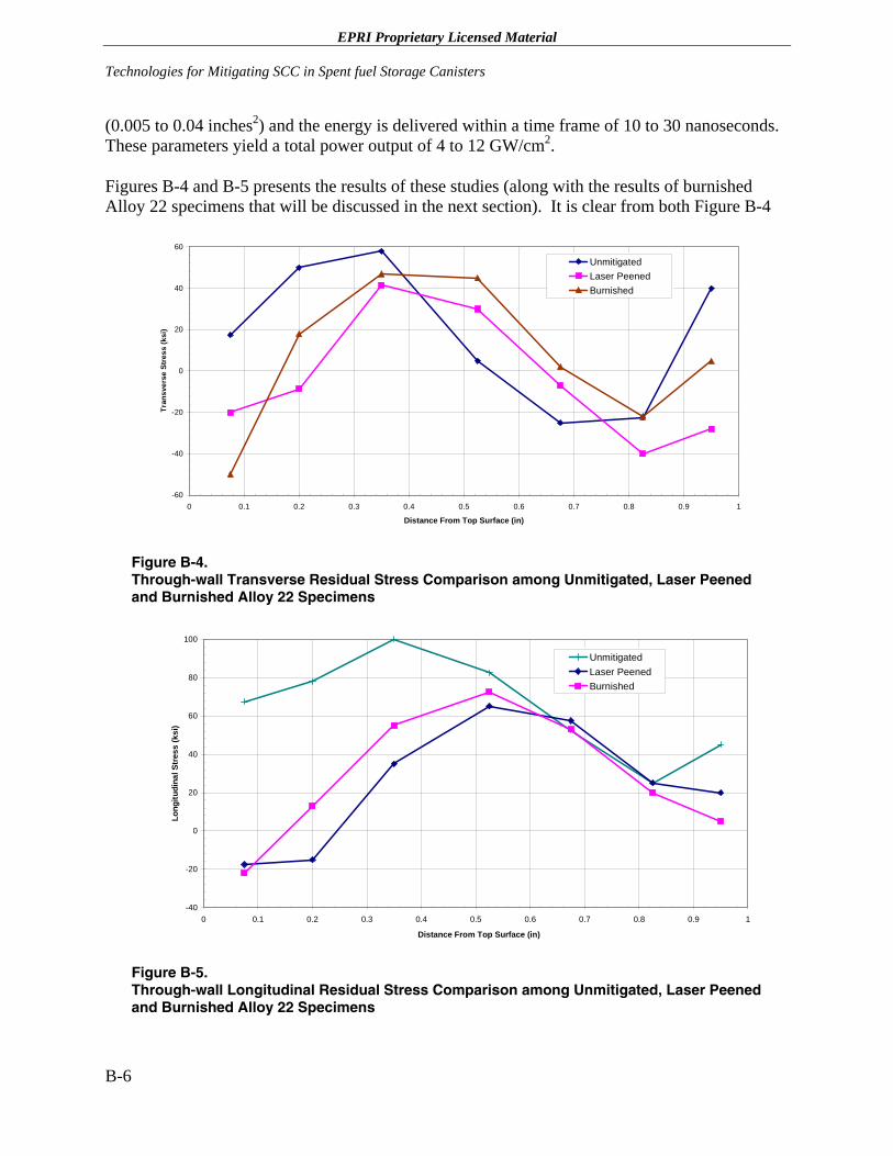
EPRI Proprietary Licensed Material Technologies for Mitigating SCC in Spent fuel Storage Canisters
(0.005 to 0.04 inches2) and the energy is delivered within a time frame of 10 to 30 nanoseconds. These parameters yield a total power output of 4 to 12 GW/cm2.
Figures B-4 and B-5 presents the results of these studies (along with the results of burnished Alloy 22 specimens that will be discussed in the next section). It is clear from both Figure B-4
-60
-40
-20
0
20
40
60
0 0.1 0.2 0.3 0.4 0.5 0.6 0.7 0.8 0.9 1
Distance From Top Surface (in)
Tran
sver
se S
tres
s (k
si)
UnmitigatedLaser PeenedBurnished
Figure B-4. Through-wall Transverse Residual Stress Comparison among Unmitigated, Laser Peened and Burnished Alloy 22 Specimens
-40
-20
0
20
40
60
80
100
0 0.1 0.2 0.3 0.4 0.5 0.6 0.7 0.8 0.9 1
Distance From Top Surface (in)
Long
itudi
nal S
tres
s (k
si)
UnmitigatedLaser PeenedBurnished
Figure B-5. Through-wall Longitudinal Residual Stress Comparison among Unmitigated, Laser Peened and Burnished Alloy 22 Specimens
B-6
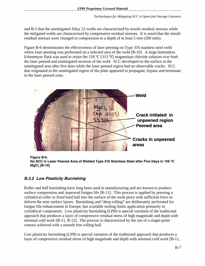
EPRI Proprietary Licensed Material
Technologies for Mitigating SCC in Spent fuel Storage Canisters
and B-5 that the unmitigated Alloy 22 welds are characterized by tensile residual stresses while the mitigated welds are characterized by compressive residual stresses. It is noted that the tensile residual stresses were changed to compression to a depth of at least 5 mm (200 mils).
Figure B-6 demonstrates the effectiveness of laser peening on Type 316 stainless steel weld where laser peening was performed on a selected area of the weld [B-10]. A large bottomless Erlenmeyer flask was used to retain the 156 ºC (313 ºF) magnesium chloride solution over both the laser peened and unmitigated sections of the weld. SCC developed on the surface at the unmitigated area after five days while the laser peened region had no observable cracks. SCC that originated in the unmitigated region of the plate appeared to propagate, bypass and terminate in the laser peened zone.
Crack initiated inunpeened regionPeened area
Cracks in unpeened areas
Weld
Crack initiated inunpeened regionPeened area
Cracks in unpeened areas
Weld
Figure B-6. No SCC in Laser Peened Area of Welded Type 316 Stainless Steel after Five Days in 156 ºC MgCl2 [B-10]
B.3.2 Low Plasticity Burnishing
Roller and ball burnishing have long been used in manufacturing and are known to produce surface compression and improved fatigue life [B-11]. This process is applied by pressing a cylindrical roller or fixed hard ball into the surface of the work piece with sufficient force to deform the near surface layers. Burnishing and “deep rolling” are deliberately performed for fatigue life enhancement in Europe, but available tooling limits application primarily to cylindrical components. Low plasticity burnishing (LPB) is special variation of the traditional approach that produces a layer of compressive residual stress of high magnitude and depth with minimal cold work [B-11, B-12]. The process is characterized by the use of a single-point contact achieved with a smooth free rolling ball.
Low plasticity burnishing (LPB) is special variation of the traditional approach that produces a layer of compressive residual stress of high magnitude and depth with minimal cold work [B-11,
B-7
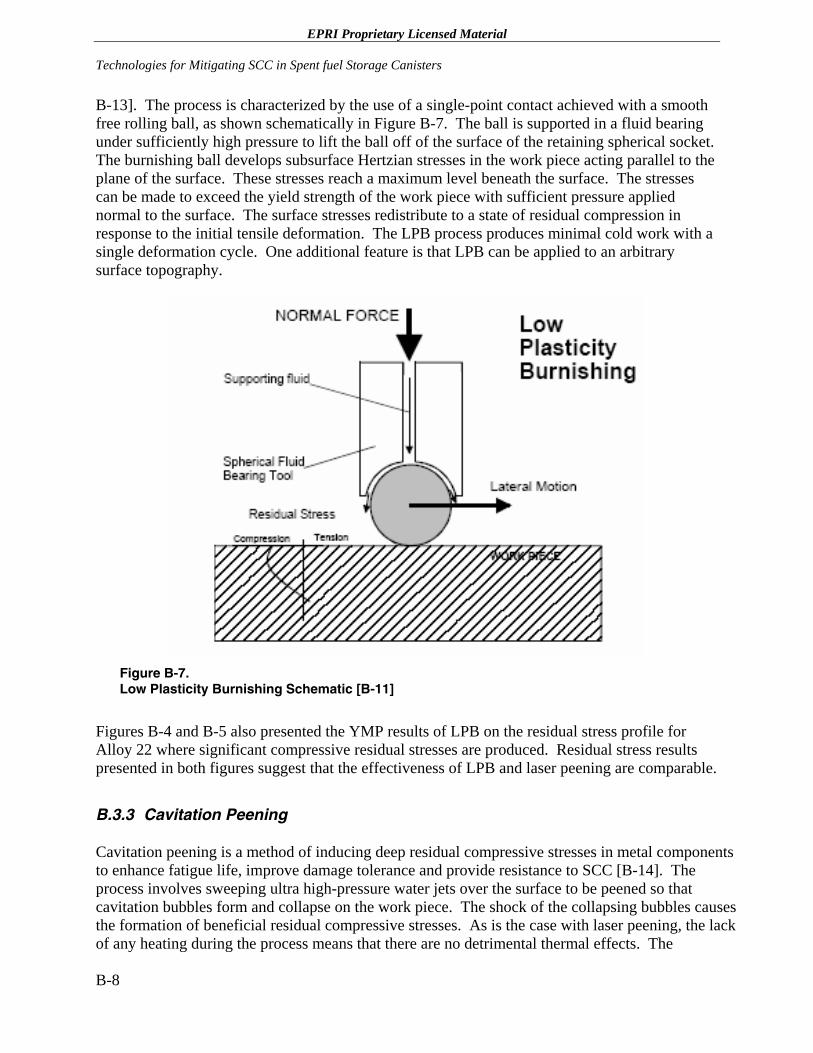
EPRI Proprietary Licensed Material Technologies for Mitigating SCC in Spent fuel Storage Canisters
B-13]. The process is characterized by the use of a single-point contact achieved with a smooth free rolling ball, as shown schematically in Figure B-7. The ball is supported in a fluid bearing under sufficiently high pressure to lift the ball off of the surface of the retaining spherical socket. The burnishing ball develops subsurface Hertzian stresses in the work piece acting parallel to the plane of the surface. These stresses reach a maximum level beneath the surface. The stresses can be made to exceed the yield strength of the work piece with sufficient pressure applied normal to the surface. The surface stresses redistribute to a state of residual compression in response to the initial tensile deformation. The LPB process produces minimal cold work with a single deformation cycle. One additional feature is that LPB can be applied to an arbitrary surface topography.
Figure B-7. Low Plasticity Burnishing Schematic [B-11]
Figures B-4 and B-5 also presented the YMP results of LPB on the residual stress profile for Alloy 22 where significant compressive residual stresses are produced. Residual stress results presented in both figures suggest that the effectiveness of LPB and laser peening are comparable.
B.3.3 Cavitation Peening
Cavitation peening is a method of inducing deep residual compressive stresses in metal components to enhance fatigue life, improve damage tolerance and provide resistance to SCC [B-14]. The process involves sweeping ultra high-pressure water jets over the surface to be peened so that cavitation bubbles form and collapse on the work piece. The shock of the collapsing bubbles causes the formation of beneficial residual compressive stresses. As is the case with laser peening, the lack of any heating during the process means that there are no detrimental thermal effects. The
B-8
EPRI Proprietary Licensed Material
Technologies for Mitigating SCC in Spent fuel Storage Canisters
equipment required to accomplish cavitation peening consists of commercially available ultra-high pressure (UHP) water pumps, a custom cavitation peening nozzle and a robot, or manipulator, to move the jet over the surface to be peened.
Cavitation peening has been proposed as an alternate approach for achieving similar residual stress and performance enhancements to laser peening [B-15]. However, it appears that cavitation peening will be able to achieve the desired levels of deep residual compressive stresses at a much lower cost than laser peening. In fact, preliminary projections estimate the cost of cavitation peening to be less than 5% of the cost for laser peening. As noted above, this innovative approach uses commercially available ultra-high pressure water jets to sweep over the surface of the part generating the beneficial residual compressive stresses without eroding the base material. In addition, the high coverage cavitation peening speeds will enable the process to be used in other applications where large surface areas require compressive stresses. The fact that the capital equipment would cost so much less than laser peening to provide a financial incentive to more rapid acceptance by the utility industry. Another huge advantage of the cavitation peening process is the ability to miniaturize the application equipment so that access to restricted locations may be possible. The applications of both laser peening and roller burnishing may be restricted for confined locations.
Much of the modeling and stress analysis performed for laser peening will be helpful for modeling the cavitation peening because the method of generating favorable stress distributions by shock waves is common to both laser peening and cavitation peening [B-15]. Testing conducted on samples with deep compressive stresses produced by laser peening should be indicative of the results expected with cavitation peening. The experience and lab testing required to qualify the laser process will guide the rigorous qualification process that cavitation peening will need to undergo for acceptance by the utility industry. Figure B-8 presents the beneficial residual stress distributions induced by cavitation peening on Type 304 stainless steel as a function of application intensity [B-14].
B-9
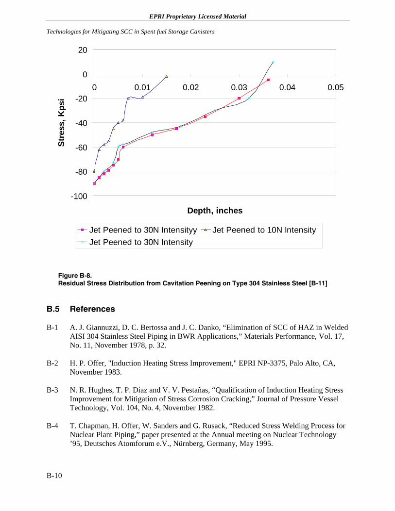
EPRI Proprietary Licensed Material Technologies for Mitigating SCC in Spent fuel Storage Canisters
-100
-80
-60
-40
-20
0
20
0 0.01 0.02 0.03 0.04 0.05
Depth, inches
Stre
ss, K
psi
Jet Peened to 30N Intensityy Jet Peened to 10N IntensityJet Peened to 30N Intensity
Figure B-8. Residual Stress Distribution from Cavitation Peening on Type 304 Stainless Steel [B-11]
B.5 References
B-1 A. J. Giannuzzi, D. C. Bertossa and J. C. Danko, “Elimination of SCC of HAZ in Welded AISI 304 Stainless Steel Piping in BWR Applications,” Materials Performance, Vol. 17, No. 11, November 1978, p. 32.
B-2 H. P. Offer, "Induction Heating Stress Improvement," EPRI NP-3375, Palo Alto, CA, November 1983.
B-3 N. R. Hughes, T. P. Diaz and V. V. Pestañas, “Qualification of Induction Heating Stress Improvement for Mitigation of Stress Corrosion Cracking,” Journal of Pressure Vessel Technology, Vol. 104, No. 4, November 1982.
B-4 T. Chapman, H. Offer, W. Sanders and G. Rusack, “Reduced Stress Welding Process for Nuclear Plant Piping,” paper presented at the Annual meeting on Nuclear Technology ’95, Deutsches Atomforum e.V., Nürnberg, Germany, May 1995.
B-10
EPRI Proprietary Licensed Material
Technologies for Mitigating SCC in Spent fuel Storage Canisters
B-5 T. Chapman, H. Offer, W. Sanders and G. Rusack, “Reduced Stress Welding Process for Nuclear Plant Piping,” Nuclear Engineering and Design, 170, 1997, p. 81.
B-6 “Shot Peening,” Curtis-Wright website, 2003.
B-7 W. R. Mohn, “Review of Processes and Techniques to Mitigate Weld Residual Stresses,” Alliance Research center report RDD:2000:43761-202-000:01R, March 2000.
B-8 M. R. Hill, et al., “Laser Peening Technology,” Advanced Materials and Processes, August 2003, p. 65.
B-9 R. Specht, “Process Control Techniques for Laser Peening of Metals,” paper presented at the 8th International Conference on Shot Peening in Garmisch-Partenkirchen, Germany, September 20, 2002.
B-10 J. Honig, et al., “Laser Peening Increases the Corrosion Resistance of Metal,” Laser Science and Technology, Program Update, UCRL-TB-136126-01-09, September 2001.
B-11 Lamda Research, “Low Plasticity Burnishing (LPB) – An Innovative Cost Effective Means of Surface Enhancement,” January 21, 2000
B-12 Surface Enhancement Technologies, “Low Plasticity Burnishing.”
B-13 Surface Enhancement Technologies, “Low Plasticity Burnishing.”
B-14 T. Butler, “Cavitation Peening,” Ormond, LLC., 2003.
B-15 T. Butler, “Cavitation Peening to Enhance Turbine Engine Component High Cycle Fatigue Life,” Ormond, LLC., August 2003.
B-11

EPRI Proprietary Licensed Material
C PRACTICAL ISSUES FOR SPENT FUEL STORAGE CANISTERS
C.1 Introduction
The construction of spent fuel storage canister/concrete storage systems involves the conceptual design, structural, thermal, criticality, shielding and material corrosion analysis, fabrication, spent fuel loading and inspection/flaw disposition. The licensing process and concept of operation for independent spent fuel storage installations (ISFSIs) in the United States have evolved over time [C-1]. Early considerations were based upon the safe storage of spent fuel in an existing reactor's spent fuel pool. In 1980, 10 CFR Part 72 was initially developed with the idea of a wet storage environment for spent fuel (e.g., GE-Morris facility). As dry cask storage technology evolved, consideration expanded to include storage of spent fuel in casks on a storage pad on a reactor site. The Nuclear Waste Policy Act mandated that the use of dry cask storage technologies be permitted under a general license; therefore, in 1990, 10 CFR Part 72 was modified to incorporate these provisions.
C.2 NRC Guidelines for Licensing Spent fuel Storage Canisters
The following is a summary of the US NRC outline for licensing spent fuel storage canisters emphasizing the non-licensing and materials issues in the process:
1. Analyses Requirements
A. Evaluations
1. Select pad site - Evaluate site characteristics against the cask design criteria cask to ensure that the cask is compatible with the selected site particularly in the following areas:
Soil Tornado missiles Earthquake intensity Cask transfer route Off-site dose limits
2. Design pad and associated components or systems
C-1
EPRI Proprietary Licensed Material Practical Issues for Spent fuel Storage Canisters
B. Programs, plans and processes to support the ISFSI
1. Welding program
Develop cask weld processes Qualify weld procedures Train and qualify welders and weld inspectors
2. Inspection program. Develop inspections procedures for:
Cleanliness Welds Non-destructive examination Cask components Fabrication activities Completed cask Coatings, paint, plating, metal spray, etc. (if used)
3. Surveillance and maintenance programs
a. Develop routine inspection and maintenance procedures
Daily visual vent inspection Daily temperature monitoring
b. Develop long term inspection and maintenance procedures
Annual cask system inspection 5-year cask system inspection
4. Fuel inspection
Define criteria for fuel selection using bounding conditions in the design basis document of the dry storage system Establish requirements and criteria for fuel inspection Define criteria for selecting position of fuel in cask Develop loading procedures Characterize each assembly for content, burn-up and condition
2. Monitor fabrication of ISFSI components and auxiliary equipment
A. Perform periodic audits and surveillances
Welds Grinding Material tolerances
C-2
EPRI Proprietary Licensed Material
Practical Issues for Spent fuel Storage Canisters
Chemical expiration dates Concrete aggregate and pour control, and testing Neutron absorbing materials (e.g., resins)
B. Evaluate design changes with cask designer for regulatory compliance and system operation
3. Conduct pre-operational activities
A. Conduct start-up testing
Conduct functional tests on casks, individual components and ancillary devices Verify engineering evaluations
B. Evaluate component fit-up
Compatibility of components including mating surfaces and clearances
Finally, there are a number of useful regulatory guides, reports, inspection manuals and inspection procedures that would be useful references for addressing the practical issues of spent fuel storage canisters/concrete storage systems:
1. Regulation 10 CFR Part 72, “Licensing Requirements for the Storage of Spent Nuclear Fuel and High-Level Radioactive Waste”
2. Regulatory Guide 3.60, “Design of an Independent Spent Fuel Storage Installation (Dry Storage)”
3. NUREG-1571, “Information Handbook on Independent Spent Fuel Storage Installations”
4. NUREG-1526, “Standard Review Plan for Dry Cask Storage System”
5. NUREG/CR-6314, “Quality Assurance Inspections for Shipping and Storage Containers”
6. NRC Inspection Manual Chapter 2690, "Inspection Program for Dry Storage of Spent Reactor Fuel at Independent Spent Fuel Storage Installations"
7. NRC Inspection Procedure IP 46051, Structural Concrete Procedure Review
8. NRC Inspection Procedure IP 60851, Design Control of ISFSI Components
9. NRC Inspection Procedure IP 60853, On-Site Fabrication of Components and Construction of an ISFSI
10. NRC Inspection Procedure IP 60854, Preoperational Testing of an ISFSI
C-3
EPRI Proprietary Licensed Material Practical Issues for Spent fuel Storage Canisters
11. NRC Inspection Procedure IP 60855, Operation of an ISFSI
C.3 Reference
C-1 US NRC, “General License Considerations for Spent Fuel Storage in an Independent Spent Fuel Storage Installation at a Reactor Site”
C-4
EPRI Proprietary Licensed Material
D-1
D CRACK LEAK RATE SAMPLE CALCULATIONS
EPRI Proprietary Licensed Material Crack Leak Rate Sample calculations
D-2
EPRI Proprietary Licensed Material
Crack Leak Rate Sample calculations
D-3
EPRI Proprietary Licensed Material Crack Leak Rate Sample calculations
D-4
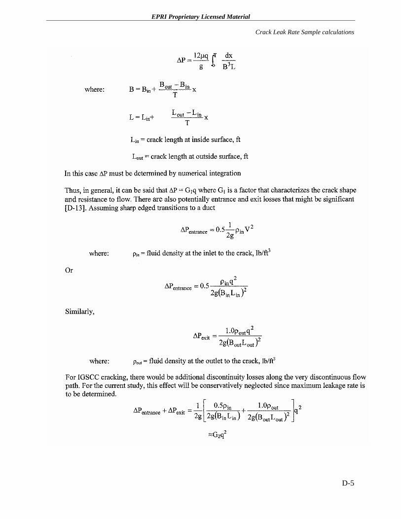
EPRI Proprietary Licensed Material
Crack Leak Rate Sample calculations
D-5
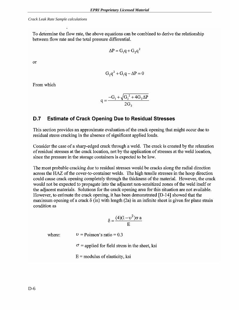
EPRI Proprietary Licensed Material Crack Leak Rate Sample calculations
D-6
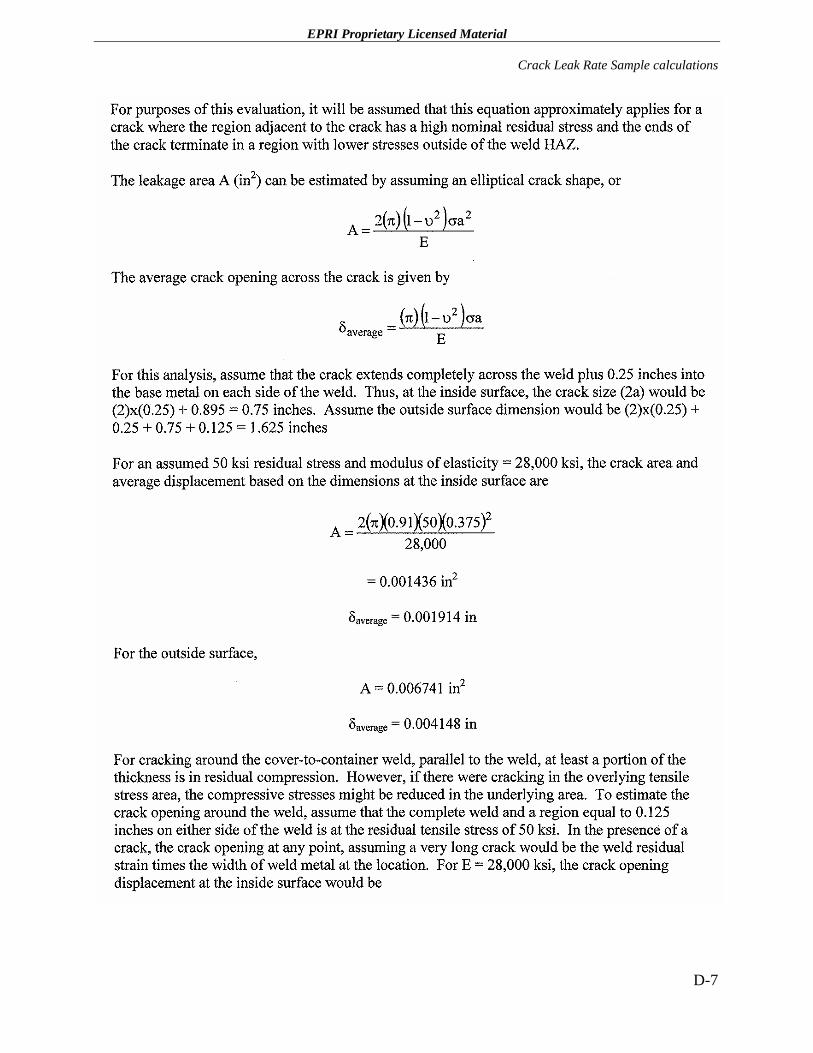
EPRI Proprietary Licensed Material
Crack Leak Rate Sample calculations
D-7
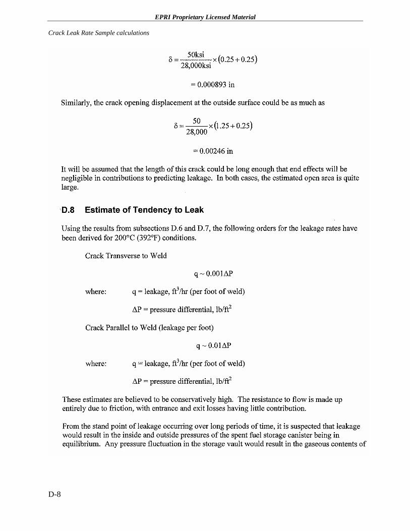
EPRI Proprietary Licensed Material Crack Leak Rate Sample calculations
D-8
EPRI Proprietary Licensed Material
Crack Leak Rate Sample calculations
D-9
EPRI Proprietary Licensed Material Crack Leak Rate Sample calculations
D-10
.
EPRI Proprietary Licensed Material
E CANDIDATE MATERIALS OF CONSTRUCTION FOR SPENT FUEL STORAGE CANISTERS EXPOSED TO MARINE ENVIRONMENTS
E.1 Introduction
Since tens of millions of dollars have been spent on the materials selection process for the waste packages for the Yucca Mountain Project (YMP) where the waste packages are designed to retain their structural integrity for approximately 10,000 years, there is a significant amount of information on the relative corrosion resistance of spent fuel storage canister candidate materials exposed to both dilute and concentrated brine solutions.
Although the waste packages at YM will not, in all likelihood, be immersed in water because the repository is well above the water table, water does permeate the mountain from the ground surface down to the water table. Consequently, the YM waste packages will be exposed to air with high relative humidity just as the case of spent fuel storage canisters at marine-type locations. There is also a possibility that water droplets will fall onto the YM waste packages where water seeps into the emplacement drifts. The surrounding rock will increase in temperature from heat given off by the spent nuclear fuel, while the repository will remain at ambient, atmospheric pressure. Under these conditions, corrosion is the most significant potential degradation mode for waste package materials.
E.2 Waste Package Candidate Alloys
Candidate materials for high level waste (HLW) canisters and overpacks are generally metals such as copper, iron, stainless steels, titanium alloys and nickel-based alloys [E-1, E-2]. Carbon steel was initially considered as the structurally strong outer layer for corrosion allowance material in the YM waste package design, but did offer suitable corrosion resistance. Nickel-based alloys are highly corrosion resistant and are quite weldable, but are relatively expensive. Stainless steels have good mechanical properties and are fairly corrosion resistant in brine environments, but catastrophic failures are possible through SCC or intergranular corrosion [E-2].
After years of corrosion testing in a varity of postulated YM dilute and concentrated environments, nickel-base Alloy 22 was selected for the corrosion barrier for the YM waste packages since it has excellent corrosion resistance over a wide range of aqueous solution compositions and temperatures [E-3]. The two major considerations are the fabrication processes for the manufacture of waste packages and the time-temperature conditions of the repository. Fabrication processes, particularly welding, can have a major impact on corrosion
E-1
EPRI Proprietary Licensed Material Candidate Materials of Construction for Spent fuel Storage Canisters Exposed to Marine Environments
resistance and performance while temperature has major effects on the composition of the environment and the behavior of materials.
E.3 YMP Overall Findings
As noted in subsection E.2, based on the body of technical information currently available, it was concluded that Alloy 22 is a suitable material of construction for the outer barrier of a waste package. Although the technical basis supporting the suitability of Alloy 22 is substantial and growing, there will always be uncertainty in the evaluation of the long-term performance of materials in the repository [E-3]. This is primarily because of the extremely long life required for the waste packages.
Although the nominal waters at Yucca Mountain are fairly benign and not corrosive, water composition can change at the metal surface. The range of environments that could exist on these surfaces depends on the composition of waters that can enter the drifts and changes to the environment that can occur on hot metal surfaces and in crevices [E-3]. Three conditions describe the surfaces of metal that will be subject to corrosion at Yucca Mountain: accumulated dust and particulate on the metal, deposits and scale on the metal and tight areas of contact (crevices) between metals. Of course, moisture must be present for corrosion to occur under any of these conditions.
E.3.1 YM Corrosion Degradation Modes
Three corrosion failure modes were identified for the candidate YM waste packages materials: general corrosion, localized corrosion and SCC. It was concluded that there is a substantial and growing technical basis to support the evaluation of the long-term performance of YM waste package materials in each of these areas.
General Corrosion. Failure of the YM waste package by uniform corrosion is unlikely. The long-term corrosion behavior is determined by the structure and composition of the passive film on Alloy 22. The passive film is influenced by thermal treatments during waste package fabrication, dry exposure periods in the repository and the exposure to aqueous environments when the surfaces become wet. Work is underway to better understand the structure and composition of the passive film under these conditions and to relate that to the long-term corrosion behavior. It was concluded that if the environmental conditions do not cause film-breakdown and localized corrosion or if the underlying metal does not undergo detrimental metallurgical changes to destabilize the film, then it is highly likely that the passive film will remain stable and uniform corrosion rates will remain very low [E-3].
However, there are two phenomena that could jeopardize the desirable long-term behavior are worthy of study: (a) surface segregation of sulfur and (b) transpassive corrosion. Surface segregation of sulfur can occur as a result of thermal treatments (equilibrium segregation) and as a result of uniform corrosion (anodic segregation). Reducing the bulk sulfur concentration of the alloy can minimize both thermal segregation and anodic segregation of sulfur. Transpassive corrosion might be caused by radiolysis of water sitting on the surface of the waste package (a
E-2
EPRI Proprietary Licensed Material
Candidate Materials of Construction for Spent fuel Storage Canisters Exposed to Marine Environments
process that is unlikely to produce transpassive potentials) and/or by a combination of all of the following: low pH, Fe+3 (from corrosion of steel structures), some amount of radiolysis of the water, and an inhomogeneous alloy microstructure (e.g., grain boundary segregated phosphorus, precipitates rich in chromium and molybdenum).
Localized Corrosion. Alloy 22 is extremely resistant to localized corrosion, i.e., its has exhibited no evidence of pitting or crevice corrosion after four-year exposures to environments similar to those that may form on waste packages in a Yucca Mountain repository at temperatures up to 85ºC (185°F). Nevertheless, Alloy 22 is susceptible to crevice corrosion under extreme conditions of environment and potential.
Stress Corrosion Cracking. The mitigation method, experimental approach and modeling efforts for SCC are consistent with the state-of-the-art, and appropriate work generally is underway to verify the models. Research to date shows that nickel base Alloy 22 is highly resistant to SCC in the environments expected in the repository. Modeling is an essential component of the SCC program, because the laboratory test techniques have inadequate sensitivity to crack growth for the prediction of acceptable long term performance of the waste package.
It has been recommended that the effectiveness of heat treatment for stress mitigation be thoroughly evaluated by finite-element thermal and stress analysis and by residual stress measurements on prototype containers and that the SCC behavior of Alloy 22 be evaluated with different stages of aging and in environments containing trace impurities, such as lead, that may influence cracking behavior.
E.4 References
E-1 M. Yim and K. L. Murty, “Materials Issues in Nuclear-Waste Management,” Journal of Metals, Vol. 52, Issue 9, September 2000, p. 26.
E-2 R. D. McCright, et al., “Candidate Container Materials for Yucca Mountain Waste Package Design,” Proc. Nuclear Waste Packaging Focus ’91 Conf. ANS, La Grange Park, IL, 1991.
E-3 J. A. Beavers, et al., “Final Report Waste Package Materials Performance Peer Review Panel,” February 28, 2002.
E-3


ELECTRIC POWER RESEARCH INSTITUTE 3420 Hillview Avenue, Palo Alto, California 94304-1395 • PO Box 10412, Palo Alto, California 94303-0813 • USA
800.313.3774 • 650.855.2121 • [email protected] • www.epri.com
Export Control Restrictions
Access to and use of EPRI Intellectual Property is granted with the specific understanding and requirement that responsibility for ensuring full compliance with all applicable U.S. and foreign export laws and regulations is being undertaken by you and your company. This includes an obligation to ensure that any individual receiving access hereunder who is not a U.S. citizen or permanent U.S. resident is permitted access under applicable U.S. and foreign export laws and regulations. In the event you are uncertain whether you or your company may lawfully obtain access to this EPRI Intellectual Property, you acknowledge that it is your obligation to consult with your company’s legal counsel to determine whether this access is lawful. Although EPRI may make available on a case-by-case basis an informal assessment of the applicable U.S. export classification for specific EPRI Intellectual Property, you and your company acknowledge that this assessment is solely for informational purposes and not for reliance purposes. You and your company acknowledge that it is still the obligation of you and your company to make your own assessment of the applicable U.S. export classification and ensure compliance accordingly. You and your company understand and acknowledge your obligations to make a prompt report to EPRI and the appropriate authorities regarding any access to or use of EPRI Intellectual Property hereunder that may be in violation of applicable U.S. or foreign export laws or regulations.
The Electric Power Research Institute (EPRI)
The Electric Power Research Institute (EPRI), with major locations in Palo Alto, California, and Charlotte, North Carolina, was established in 1973 as an independent, nonprofit center for public interest energy and environmental research. EPRI brings together members, participants, the Institute’s scientists and engineers, and other leading experts to work collaboratively on solutions to the challenges of electric power. These solutions span nearly every area of electricity generation, delivery, and use, including health, safety, and environment. EPRI’s members represent over 90% of the electricity generated in the United States. International participation represents nearly 15% of EPRI’s total research, development, and demonstration program.
Together…Shaping the Future of Electricity
© 2005 Electric Power Research Institute (EPRI), Inc. All rights reserved. Electric Power Research Institute and EPRI are registered service marks of the Electric Power Research Institute, Inc.
Printed on recycled paper in the United States of America 1011820
Related Documents